2 team #2 - ortop · releasing ps ... data log analysis ----- 125. team #2 vii thursday 3/19/2009,...
TRANSCRIPT


2 Team #2

Team #2 i
Table of Contents
Sunday 9/14/2008, 2:00-6:00pm -------------------------------------------------------------------------------------- 1
Kick-off Meeting -------------------------------------------------------------------------------------------------------- 1 Game Observations -------------------------------------------------------------------------------------------------- 1 Tetrix Kit --------------------------------------------------------------------------------------------------------------- 1
Thursday 9/18/2008, 6:30-9:00pm ----------------------------------------------------------------------------------- 2 Building Square Bot -------------------------------------------------------------------------------------------------- 2 Running 1st Robot ----------------------------------------------------------------------------------------------------- 2
Sunday 9/21/2008, 1:00-4:00pm -------------------------------------------------------------------------------------- 4 Robot Requirements -------------------------------------------------------------------------------------------------- 4 Autonomous mode thoughts ----------------------------------------------------------------------------------------- 4 Robot ideas for handling pucks ------------------------------------------------------------------------------------- 5 Getting off of the ramp ----------------------------------------------------------------------------------------------- 5 Collecting pucks from the rack: ------------------------------------------------------------------------------------ 5
Thursday 9/25/2008, 6:30-8:30pm ----------------------------------------------------------------------------------- 6
Saturday 9/27/2008, 3:30-5:00pm ------------------------------------------------------------------------------------ 7 Sensor Exploration --------------------------------------------------------------------------------------------------- 7
Sunday 9/28/2008, 1:00-4:00pm -------------------------------------------------------------------------------------- 8 Stacker Bot ------------------------------------------------------------------------------------------------------------ 8 Robot Actions --------------------------------------------------------------------------------------------------------- 8 Robot Elements ------------------------------------------------------------------------------------------------------- 9
Sunday 10/5/2008, 1:00-3:00pm ------------------------------------------------------------------------------------- 10 Robot Ramp Climbing ----------------------------------------------------------------------------------------------- 10 Ultra-sonic sensor performance ----------------------------------------------------------------------------------- 11
Sunday 10/12/2008, 1:00-3:00pm ----------------------------------------------------------------------------------- 12
Sunday 10/19/2008, 1:00-3:00pm ----------------------------------------------------------------------------------- 13
Thursday 10/23/2008, 6:30-8:00pm -------------------------------------------------------------------------------- 15 Skid-steer Robot Base ----------------------------------------------------------------------------------------------- 15 Mindsensor’s Distance Sensor Evaluation ----------------------------------------------------------------------- 16
Sunday 10/26/2008, 1:00-3:00pm ----------------------------------------------------------------------------------- 18 Skid-steer Base Evaluation ----------------------------------------------------------------------------------------- 18

ii Team #2
Puck Holder Experiments ------------------------------------------------------------------------------------------ 19
Sunday 11/2/2008, 1:00-3:00pm ------------------------------------------------------------------------------------- 20 Navigation Requirements ------------------------------------------------------------------------------------------- 20 Specs from Sharp Sensors ------------------------------------------------------------------------------------------ 20 Vertical Sensor Orientation ---------------------------------------------------------------------------------------- 21 Which Sensor to Use ------------------------------------------------------------------------------------------------ 21
Thursday 11/6/2008, 6:30-8:00pm ---------------------------------------------------------------------------------- 22 Releasing Pucks ------------------------------------------------------------------------------------------------------ 22 Compass Navigation ------------------------------------------------------------------------------------------------ 23
Sunday 11/9/2008, 1:30-4:00pm ------------------------------------------------------------------------------------- 24 Releasing Pucks ------------------------------------------------------------------------------------------------------ 24 Compass Navigation ------------------------------------------------------------------------------------------------ 24
Thursday 11/13/2008, 6:30-8:00pm -------------------------------------------------------------------------------- 25 Compass Wrap Issues ----------------------------------------------------------------------------------------------- 25
Sunday 11/16/2008, 1:30-4:00pm ----------------------------------------------------------------------------------- 27 Traveling Straight with Compass Sensor ------------------------------------------------------------------------- 27 Robot Detection ------------------------------------------------------------------------------------------------------ 29
Thursday 11/20/2008, 6:30-8:00pm -------------------------------------------------------------------------------- 30 Center Goal Scoring ------------------------------------------------------------------------------------------------ 30
Sunday 11/23/2008, 1:30-3:30pm ----------------------------------------------------------------------------------- 32 Hardware review ---------------------------------------------------------------------------------------------------- 32 Compass Sensor Calibration --------------------------------------------------------------------------------------- 32
Sunday 11/30/2008, 1:30-5:30pm ----------------------------------------------------------------------------------- 35 Robot functionality -------------------------------------------------------------------------------------------------- 35 Major robot components -------------------------------------------------------------------------------------------- 35 Distance sensor locations ------------------------------------------------------------------------------------------ 35 Explorations on simple puck pickup------------------------------------------------------------------------------- 36 Deciding on front-end loader design ------------------------------------------------------------------------------ 37 Compass sensor evaluations --------------------------------------------------------------------------------------- 37
Sunday 12/7/2008, 1:30-5:30pm ------------------------------------------------------------------------------------- 41 Compass Sensor Testing -------------------------------------------------------------------------------------------- 41 Mounting sensors on a servo --------------------------------------------------------------------------------------- 42
Thursday 12/11/2008, 6:30-8:00pm -------------------------------------------------------------------------------- 43

Team #2 iii
Distance Sensor Testing -------------------------------------------------------------------------------------------- 43 Searching for Appropriate Sensor --------------------------------------------------------------------------------- 43
Sunday 12/14/2008, 2:00-3:00pm ----------------------------------------------------------------------------------- 44 Plans for Sonar Usage in Autonomous --------------------------------------------------------------------------- 44
Tuesday 12/16/2008, 6:00-9:00pm ---------------------------------------------------------------------------------- 45 Arm Development ---------------------------------------------------------------------------------------------------- 45
Wednesday 12/17/2008, 7:00-10:00pm ----------------------------------------------------------------------------- 46 Sonar Sensor Attachment to Prototype Board ------------------------------------------------------------------- 46 Sonar Sensor Testing ------------------------------------------------------------------------------------------------ 47
Thursday 12/18/2008, 8:00-9:00pm -------------------------------------------------------------------------------- 48 Robot Navigation Designs ------------------------------------------------------------------------------------------ 48
Friday 12/19/2008, 6:00-7:00pm ------------------------------------------------------------------------------------ 49 Define Coding Standards ------------------------------------------------------------------------------------------- 49
Tuesday 12/23/2008, 8:00-10:00pm --------------------------------------------------------------------------------- 50 Compass Program Object ------------------------------------------------------------------------------------------ 50
Saturday 12/27/2008, 12:00-2:00pm -------------------------------------------------------------------------------- 51 Derivation of Determining Robot Location on Field ----------------------------------------------------------- 51
Sunday 12/28/2008, 1:30-5:00pm ----------------------------------------------------------------------------------- 54 Interior Design ------------------------------------------------------------------------------------------------------- 54 Arm attachment point ----------------------------------------------------------------------------------------------- 55 NXT Mounting ------------------------------------------------------------------------------------------------------- 55 Work Left to Do ------------------------------------------------------------------------------------------------------ 56
Thursday 1/2/2009, 6:30-9:00pm ----------------------------------------------------------------------------------- 57 Scoop ------------------------------------------------------------------------------------------------------------------ 57 Robot SW ------------------------------------------------------------------------------------------------------------- 57
Sunday 1/5/2009, 1:00-5:00pm -------------------------------------------------------------------------------------- 58 Scoop ------------------------------------------------------------------------------------------------------------------ 58 Tele-op Software ----------------------------------------------------------------------------------------------------- 58
Thursday 1/8/2009, 5:30-8:00pm ----------------------------------------------------------------------------------- 60 Testing ---------------------------------------------------------------------------------------------------------------- 60
Sunday 1/11/2009, 9:00-4:30pm ------------------------------------------------------------------------------------- 61 Tele-op Software ----------------------------------------------------------------------------------------------------- 61 Securing NXT and Battery ------------------------------------------------------------------------------------------ 66

iv Team #2
Thursday 1/15/2009, 6:30-8:00pm ---------------------------------------------------------------------------------- 67 Scoop ------------------------------------------------------------------------------------------------------------------ 67 Software Templates -------------------------------------------------------------------------------------------------- 67
Monday 1/19/2009, 10:30-1:30pm ---------------------------------------------------------------------------------- 68 Gear Collar Mods --------------------------------------------------------------------------------------------------- 68 Robot Location SW -------------------------------------------------------------------------------------------------- 68
Thursday 1/22/2009, 6:30-9:00pm ---------------------------------------------------------------------------------- 69 Scrimmage Problems ------------------------------------------------------------------------------------------------ 69 Slipping axle problem ----------------------------------------------------------------------------------------------- 69 Triangle Scoring ----------------------------------------------------------------------------------------------------- 69 Autonomous Software ----------------------------------------------------------------------------------------------- 70
Sunday 1/25/2009, 1:00-5:30pm ------------------------------------------------------------------------------------- 71 Dumping the puck racks -------------------------------------------------------------------------------------------- 71 Picking pucks off the floor ------------------------------------------------------------------------------------------ 72 Concepts for scoring into the triangle ---------------------------------------------------------------------------- 72 New robot layout notes --------------------------------------------------------------------------------------------- 75
Tuesday 1/27/2009, 6:00-8:30pm ------------------------------------------------------------------------------------ 76 Scoop ------------------------------------------------------------------------------------------------------------------ 76 Debug Autonomous Software -------------------------------------------------------------------------------------- 76
Thursday 1/29/2009, 6:00-8:30pm ---------------------------------------------------------------------------------- 77 Prepare for Scrimmage --------------------------------------------------------------------------------------------- 77 Hopper ---------------------------------------------------------------------------------------------------------------- 77 Build Proto-board --------------------------------------------------------------------------------------------------- 78
Tuesday 2/3/2009, 1:00-8:30pm ------------------------------------------------------------------------------------- 80 Test sensor package ------------------------------------------------------------------------------------------------- 80 Test compass sensor operation ------------------------------------------------------------------------------------ 80 Rebuild Robot -------------------------------------------------------------------------------------------------------- 80 Building the IR Distance Sensor on proto-board ---------------------------------------------------------------- 81
Friday 2/6/2009, 6:00-10:00pm -------------------------------------------------------------------------------------- 83 Robot rebuild --------------------------------------------------------------------------------------------------------- 83
Sunday 2/8/2009, 2:00-5:00pm -------------------------------------------------------------------------------------- 84 4.3 Volt Power Usage ----------------------------------------------------------------------------------------------- 84 Sensor Sampling Rate and Noisy Readings ---------------------------------------------------------------------- 84 Sensor Mounting Issues --------------------------------------------------------------------------------------------- 84

Team #2 v
Robot rebuild --------------------------------------------------------------------------------------------------------- 86
Tuesday 2/10/2009, 5:00-9:00pm ------------------------------------------------------------------------------------ 87 IR Sensor Board ----------------------------------------------------------------------------------------------------- 87 Robot Interior -------------------------------------------------------------------------------------------------------- 90 Compass Mount ------------------------------------------------------------------------------------------------------ 90
Thursday 2/12/2009, 6:00-9:00pm ---------------------------------------------------------------------------------- 91 Issue List -------------------------------------------------------------------------------------------------------------- 91 IR Sensor Mounting ------------------------------------------------------------------------------------------------- 91 Bucket Prototype ----------------------------------------------------------------------------------------------------- 92 Bugs Fixed ------------------------------------------------------------------------------------------------------------ 93
Friday 2/13/2009, 7:30-9:00pm -------------------------------------------------------------------------------------- 94 Measuring Compass Error ----------------------------------------------------------------------------------------- 94 Algorithm for calibrating compass -------------------------------------------------------------------------------- 95
Saturday 2/14/2009, 12:00-6:00pm --------------------------------------------------------------------------------- 97 Compass calibration software ------------------------------------------------------------------------------------- 97 Rack Tripper --------------------------------------------------------------------------------------------------------- 98 Distance Sensor Mounting ----------------------------------------------------------------------------------------- 98 Bugs Fixed ------------------------------------------------------------------------------------------------------------ 98
Sunday 2/15/2009, 1:00-6:00pm ------------------------------------------------------------------------------------- 99 Distance Sensor ------------------------------------------------------------------------------------------------------ 99 Arm Placement ----------------------------------------------------------------------------------------------------- 100
Monday 2/16/2009, 12:00-6:00pm -------------------------------------------------------------------------------- 101 Distance Sensor Calibration ------------------------------------------------------------------------------------- 101 Robot Arm ---------------------------------------------------------------------------------------------------------- 104
Tuesday 2/17/2009, 6:00-9:00pm ---------------------------------------------------------------------------------- 105 Autonomous -------------------------------------------------------------------------------------------------------- 105 Arm Design --------------------------------------------------------------------------------------------------------- 105 Bugs Fixed ---------------------------------------------------------------------------------------------------------- 105
Thursday 2/19/2009, 6:00-10:00pm ------------------------------------------------------------------------------ 106 Tele-op Controls --------------------------------------------------------------------------------------------------- 106 Autonomous -------------------------------------------------------------------------------------------------------- 106 Arm Design --------------------------------------------------------------------------------------------------------- 106 Bucket Design ------------------------------------------------------------------------------------------------------ 107 Bugs Fixed ---------------------------------------------------------------------------------------------------------- 107

vi Team #2
Friday 2/20/2009, 4:00-11:00pm ---------------------------------------------------------------------------------- 108 Autonomous -------------------------------------------------------------------------------------------------------- 108 Bucket --------------------------------------------------------------------------------------------------------------- 108 Sensor Bay ---------------------------------------------------------------------------------------------------------- 109 Bugs Fixed ---------------------------------------------------------------------------------------------------------- 109
Saturday 2/21/2009, 9:00am-11:00pm --------------------------------------------------------------------------- 110 Issue List ------------------------------------------------------------------------------------------------------------ 110 Mount NXT and Sensors ------------------------------------------------------------------------------------------ 111 Finish Bucket Design ---------------------------------------------------------------------------------------------- 111 Design Tripper ----------------------------------------------------------------------------------------------------- 112 Autonomous Software --------------------------------------------------------------------------------------------- 112 Bugs Fixed ---------------------------------------------------------------------------------------------------------- 113
Sunday 3/1/2009, 1:00-4:00pm ------------------------------------------------------------------------------------ 114 Hardware Issues --------------------------------------------------------------------------------------------------- 114 Software issues ----------------------------------------------------------------------------------------------------- 116
Thursday 3/5/2009, 6:00-8:00pm --------------------------------------------------------------------------------- 117 Pucks getting stuck in the bucket -------------------------------------------------------------------------------- 117 Tripper -------------------------------------------------------------------------------------------------------------- 117
Sunday 3/8/2009, 1:00-5:00pm ------------------------------------------------------------------------------------ 118 Erratic Software --------------------------------------------------------------------------------------------------- 118 Tripper -------------------------------------------------------------------------------------------------------------- 118
Thursday 3/12/2009, 6:00-8:00pm -------------------------------------------------------------------------------- 119 Robot Stability ----------------------------------------------------------------------------------------------------- 119
Sunday 3/15/2009, 1:00-6:00pm ----------------------------------------------------------------------------------- 120 Issue List ------------------------------------------------------------------------------------------------------------ 120 Compass Sensor --------------------------------------------------------------------------------------------------- 121 Autonomous Software --------------------------------------------------------------------------------------------- 121 Distance Sensors --------------------------------------------------------------------------------------------------- 121 Tripper -------------------------------------------------------------------------------------------------------------- 121 Gear Slippage ------------------------------------------------------------------------------------------------------ 122 Bugs Fixed ---------------------------------------------------------------------------------------------------------- 122
Tuesday 3/17/2009, 7:00-10:00pm -------------------------------------------------------------------------------- 123 Capturing the Data Log ------------------------------------------------------------------------------------------ 123 Data Log Analysis ------------------------------------------------------------------------------------------------- 125

Team #2 vii
Thursday 3/19/2009, 7:00-9:00pm -------------------------------------------------------------------------------- 126 Picking pucks off mat --------------------------------------------------------------------------------------------- 126 Compass Errors ---------------------------------------------------------------------------------------------------- 127 Tele-op Practice --------------------------------------------------------------------------------------------------- 127
Sunday 3/22/2009, 1:00-7:00pm ----------------------------------------------------------------------------------- 128 Getting off the ramp in autonomous ----------------------------------------------------------------------------- 128 Working around compass sensor accuracy -------------------------------------------------------------------- 129 Turning using rotation sensors ---------------------------------------------------------------------------------- 129 IR distance sensor position correction -------------------------------------------------------------------------- 130 Letting the front IR sensor see out ------------------------------------------------------------------------------- 130 Positioning the IR sensor ----------------------------------------------------------------------------------------- 131
Tuesday 3/24/2009, 6:00-8:00pm ---------------------------------------------------------------------------------- 132 Picking Pucks off the Mat ---------------------------------------------------------------------------------------- 132 Getting Consistent Measurements ------------------------------------------------------------------------------- 132
Thursday 3/26/2009, 6:00-9:00pm -------------------------------------------------------------------------------- 133 Running I2CSendMsg in background --------------------------------------------------------------------------- 133 Getting Tasks to run at even intervals -------------------------------------------------------------------------- 133 Synchronizing main and updateLocation Tasks --------------------------------------------------------------- 133 Picking Pucks off the Mat ---------------------------------------------------------------------------------------- 134
Sunday 3/29/2009, 1:00-6:00pm ----------------------------------------------------------------------------------- 135 Puck Pickup on Mat ----------------------------------------------------------------------------------------------- 135 Compass Sensor Errors ------------------------------------------------------------------------------------------- 135 Hardware Issues List ---------------------------------------------------------------------------------------------- 136 Redo Robot Interior ----------------------------------------------------------------------------------------------- 136 Flag Holder Relocation ------------------------------------------------------------------------------------------- 137
Tuesday 3/31/2009, 6:00-8:00pm ---------------------------------------------------------------------------------- 138 Puck Tripper ------------------------------------------------------------------------------------------------------- 138 Small Angle Turning ---------------------------------------------------------------------------------------------- 138
Thursday 4/02/2009, 6:00-9:00pm -------------------------------------------------------------------------------- 139 Puck Tripper ------------------------------------------------------------------------------------------------------- 139 Robot Logo --------------------------------------------------------------------------------------------------------- 140 Autonomous Small Turns ----------------------------------------------------------------------------------------- 141
Sunday 4/05/2009, 1:00-5:00pm ----------------------------------------------------------------------------------- 142 Tripper Design ----------------------------------------------------------------------------------------------------- 142

viii Team #2
Logo ----------------------------------------------------------------------------------------------------------------- 142 Small Turn Control ------------------------------------------------------------------------------------------------ 143
Tuesday 4/07/2009, 5:00-9:30pm ---------------------------------------------------------------------------------- 146 DC Motor Failure ------------------------------------------------------------------------------------------------- 146 Scrimmage ---------------------------------------------------------------------------------------------------------- 146
Thursday 4/09/2009, 5:00-9:00pm -------------------------------------------------------------------------------- 148 Tripper -------------------------------------------------------------------------------------------------------------- 148 Autonomous Turning ---------------------------------------------------------------------------------------------- 149 Key Software Issues ----------------------------------------------------------------------------------------------- 149

Team #2 ix
List of Figures Figure 1 – Our first Tetrix Robot ........................................................................................ 2 Figure 2 – Robot on Pipes ................................................................................................... 3 Figure 3 – Elmer and Billy running robot ........................................................................... 3 Figure 4 – Autonomous Example ....................................................................................... 5 Figure 5 – Lengthened base for stability ............................................................................. 6 Figure 6 – Hook puck capture mechanism ......................................................................... 6 Figure 7 – Robot with swivel US Sensor ............................................................................ 7 Figure 8 – Puck Grabber Thought ...................................................................................... 8 Figure 9 – Adding zip ties to see if traction is improved .................................................. 10 Figure 10 – US Sensor accurately measured object straight on. ....................................... 11 Figure 11 – Turning object at an angle makes it disappear. ............................................. 11 Figure 12 – Front-end Loader ........................................................................................... 13 Figure 13 – Side release .................................................................................................... 13 Figure 14 – Tip back to score ........................................................................................... 14 Figure 15 – Side Capture with Catapult Score .................................................................. 14 Figure 16 – Skid Steer Robot with only 2 Drive Motors .................................................. 15 Figure 17 – Results of repeated scans over same area ...................................................... 16 Figure 18 – Analysis of Distance Sensor Erratic Performance ......................................... 17 Figure 19 – Skid steer test results ..................................................................................... 18 Figure 20 – Experimental Puck Rack ............................................................................... 19 Figure 21 – Navigation Requirements .............................................................................. 20 Figure 22 – Distance Sensor scan with it oriented vertically ............................................ 21 Figure 23 – Sharp Distance Sensor Ranges ...................................................................... 21 Figure 24 – Ramp to Release Pucks ................................................................................. 22 Figure 25 – Compass Sensor Mounted on Robot ............................................................. 23 Figure 26 – Modified Ramp Puck Release ....................................................................... 24 Figure 27 – Pseudo compass wrap code ........................................................................... 25 Figure 28 – Pseudo compass wrap code (cont) ................................................................. 26 Figure 29 – Simplified Compass wrap code ..................................................................... 27 Figure 30 – Position error for small compass error .......................................................... 29 Figure 31 – Single Distance Sensor, not good enough ..................................................... 29 Figure 32 – Center Goal Scoring Model ........................................................................... 31 Figure 33 – Front-end Loader Approach .......................................................................... 32 Figure 34 – Test fixture for Calibrating Compass Sensor ................................................ 33 Figure 35 – Distance sensor approximate locations ......................................................... 36 Figure 36 – Flat plate getting under pucks........................................................................ 36 Figure 37 – Design choices for front-end loader .............................................................. 37 Figure 38 – Gearing the compass sensor down 5:1 for testing ......................................... 38 Figure 39 – Graph of Compass error of +/- 6 degrees ..................................................... 40 Figure 40 – More robust compass test fixture .................................................................. 41 Figure 41 – Tests showing error is due magnetic heading, not fixture ............................. 42 Figure 42 – Servo with distance sensor mounted ............................................................. 42 Figure 43 – Maxbotix Sensor information ........................................................................ 43

x Team #2
Figure 44 – Simple autonomous navigation plans ............................................................ 44 Figure 45 – New Robot Base Prototype ........................................................................... 45 Figure 46 – Test fixture for Sonar Sensor Tests ............................................................... 46 Figure 47 – Field Coordinates........................................................................................... 52 Figure 48 – Basic Field Position Equation ....................................................................... 53 Figure 49 – Status of current robot base ........................................................................... 54 Figure 50 – Arm Attachment Point ................................................................................... 55 Figure 51 – Experimental NXT protector ......................................................................... 55 Figure 52 – Robot with First Proto type Scoop ................................................................ 58 Figure 53 – derivation of parabolic control ...................................................................... 59 Figure 54 – Changed tubing to C-Channel for strength .................................................... 60 Figure 55 – Graphs of robot ramp up times ...................................................................... 62 Figure 56 – Graph of Joystick input to Speed ................................................................... 65 Figure 57 – Derivation of control equation ....................................................................... 65 Figure 58 – Mounting of the NXT in the chassis.............................................................. 66 Figure 59 – Robot ready for 1st Scrimmage ..................................................................... 67 Figure 60 – Gear Collar Mods .......................................................................................... 68 Figure 61 – Guide rails on the top of scoop ...................................................................... 70 Figure 62 – forces acting on the puck rack ....................................................................... 71 Figure 63 – Dumping puck concept models ..................................................................... 72 Figure 64 – Concept model for picking pucks off the floor ............................................. 72 Figure 65 – New robot dimensions ................................................................................... 75 Figure 66 – Scoop design to fit with rack tripper ............................................................. 76 Figure 67 – Movement of pucks from the floor or rack to hopper ................................... 77 Figure 68 – Measuring distances to score pucks .............................................................. 78 Figure 69 – Proto-board schematic ................................................................................... 78 Figure 70 – Soldering proto-board .................................................................................... 79 Figure 71 – Finished Sensor Module ................................................................................ 79 Figure 72 – IR DIST Sensor connected to the proto-board .............................................. 81 Figure 73 – IR Distance vs. reading measurements .......................................................... 81 Figure 74 – Oscilloscope trace of Power Supply and Signal Output Noise ..................... 82 Figure 75 – Rebuild with arm supports in and tool motor lower ...................................... 83 Figure 76 – Drawing of holes size required to IR Sensor to look through ....................... 85 Figure 77 – Bracing Tool Motor Bracket ......................................................................... 86 Figure 78 – Staggered Motor Controllers ......................................................................... 86 Figure 79 – Derivation of RC decoupling values ............................................................ 88 Figure 80 – Schematic for Sensor Board .......................................................................... 89 Figure 81 – Prototype board ready to put the sensor cables on ........................................ 89 Figure 82 – Robot Interior after reconstruction ................................................................ 90 Figure 83 – Compass Sensor Mount ................................................................................. 90 Figure 84 – IR Sensor mounting scheme .......................................................................... 92 Figure 85 – Robot with new prototype bucket .................................................................. 93 Figure 86 – Robot on turn table for measuring compass error ......................................... 94 Figure 87 – Graph of compass error ................................................................................. 95 Figure 88 – Derivation of piecewise linear interpolation ................................................. 96 Figure 89 – Rack tripper mounted on robot ...................................................................... 98

Team #2 xi
Figure 90 – Distance Sensor mounting ............................................................................. 98 Figure 91 – Distance sensor power supply noise .............................................................. 99 Figure 92 – Signal noise ................................................................................................. 100 Figure 93 – Distance Sensor Calibration Setup .............................................................. 101 Figure 94 – Graph of normal and inverse sensor data .................................................... 103 Figure 95 – Sensor Calibration Equations ...................................................................... 103 Figure 96 – Arm 4-bar linkage design ............................................................................ 104 Figure 97 – Robot with new arm design ......................................................................... 106 Figure 98 – Dimensions for Bucket ................................................................................ 107 Figure 99 – Partial bucket on Robot ............................................................................... 108 Figure 100 – Adjustable sensor mounting design ........................................................... 109 Figure 101 – NXT Mounting with Sensors..................................................................... 111 Figure 102 – New Bucket Design ................................................................................... 111 Figure 103 – Tetrix Tripper Design ................................................................................ 112 Figure 104 – Modified Compass Sensor Mount ............................................................. 113 Figure 105 – Hardware to-do list .................................................................................... 114 Figure 106 – Robot Balance and Puck Pickup ................................................................ 115 Figure 107 – Combine idea for puck pick-up ................................................................. 115 Figure 108 – Programming Issues List ........................................................................... 116 Figure 109 – New tripper design .................................................................................... 117 Figure 110 – Robot center of gravity .............................................................................. 119 Figure 111 – Finished tripper design .............................................................................. 121 Figure 112 – Double collars on gears to stop slipping.................................................... 122 Figure 113 – Datalog analysis of autonomous ................................................................ 125 Figure 114 – Beginnings of Dual Wheel Puck Pickup ................................................... 126 Figure 115 – robot tipping over coming down ramp ..................................................... 128 Figure 116 – deriving equations for rotation sensor turning ........................................... 129 Figure 117 – adjusting rotational reference .................................................................... 130 Figure 118 – IR sensor hole ............................................................................................ 130 Figure 119 – Using the IR camera to find sensor spot .................................................... 131 Figure 120 – Puck Pickup Development ........................................................................ 134 Figure 121 – Updated Robot Interior .............................................................................. 137 Figure 122 – Flag Holder Mounting ............................................................................... 137 Figure 123 – Failed Tripper Mod .................................................................................... 138 Figure 124 – Sketch of new tripper arms ........................................................................ 139 Figure 125 – Tripper arm Pieces ..................................................................................... 140 Figure 126 – Etched Logo in Polycarb ........................................................................... 140 Figure 127 – Hand painting conceals the etching effects ............................................... 141 Figure 128 – Almost completed tripper design............................................................... 142 Figure 129 – Graph of 90 degree turn test ..................................................................... 145 Figure 130 – Graph of 15 degree turn test ...................................................................... 145 Figure 131 – Graph of captured variables for Red Ground Run ..................................... 147 Figure 132 – Red Ground X, Y position showing computation errors ........................... 147 Figure 133 – Modified tripper to keep from catching on edge of rack ........................... 148

xii Team #2
List of Tables Table 1 – Key robot tasks ................................................................................................... 4 Table 2 – Distance Measurements straight on .................................................................. 47 Table 3 – Motor Ramp up Characteristics ........................................................................ 63 Table 4 – Stopping distance vs. power level ..................................................................... 64 Table 5 – Sensor Current Usage ....................................................................................... 84 Table 6 – Issues list ........................................................................................................... 91 Table 7 – Raw Distance Sensor Data .............................................................................. 102 Table 8 – Issues list ......................................................................................................... 110 Table 9 – Issues list ......................................................................................................... 120 Table 10 – Issues list ....................................................................................................... 136
Program Listings
Listing 1 – First Compass Test Program........................................................................... 34 Listing 2 – Second Compass Test Program ...................................................................... 39 Listing 3 – Sample Formatted Code ................................................................................. 50 Listing 4 – Robot Ramp up Speed Program ..................................................................... 61 Listing 5 – Stopping distance test program....................................................................... 63 Listing 6 – Program with Feedback to Control Motor Speed ........................................... 64 Listing 7 – Function to convert joystick value to speed ................................................... 66 Listing 8 – Compass calibration routine ........................................................................... 97 Listing 9 – Code to capture data to data log ................................................................... 123 Listing 10 – Program to convert Data Log to CSV file .................................................. 125 Listing 11 – Code to generate even data samples ........................................................... 133 Listing 12 – Function to synchronize Tasks ................................................................... 134 Listing 13 – Turning Test Routine .................................................................................. 144

Team #2 1
Recorded by: Date: Reviewed by: Date:
Sunday 9/14/2008, 2:00-6:00pm
Kick-off Meeting
Tasks Reflections View FIRST Game Challenge Video Discuss Game Rules With new autonomous scoring rules we
will probably spend most of our time working on the autonomous mode.
Unpack the Tetrix Kit Building strategies are going to be a lot different this year.
Game Observations • Autonomous seems to be the way to go. Because the scores count twice. • Pucks were a lot like the rings last year. • Similar scoring values as last year.
Tetrix Kit
• The motors looked powerful, • Looked sturdier. • Don’t seem to be as many building options as there was with vex. • It will take time to figure out how to build with it.

2 Team #2
Recorded by: Date: Reviewed by: Date:
Thursday 9/18/2008, 6:30-9:00pm Tasks Reflections Build a Square Bot out of Tetrix Parts It was fairly easy to put together a simple
robot, the limited kinds of parts could make more complex designs harder to build.
Check how bot works on the pipe terrain. The two motor drive has plenty of power to move the robot. Since we didn’t have power to all four wheels steering was sluggish. Driving over the pipes worked okay, however when driving over the pipes we had a tendency to get stuck. Applying power to all four wheels should fix this problem.
Building Square Bot • We worked on building on a simple robot. We used the Tetrix guide to figure out
how to best put pieces together. • The NXT battery and motor control were simply mounted anywhere we could
find a space. We just wanted to get things started quickly.
Figure 1 – Our first Tetrix Robot
• We adapted the joystick program from RobotC to control our robot.
Running 1st Robot • We discovered that the motors have plenty of power to move the robot. • We had the motors so fine control over the robot was difficult.

Thursday 9/18/2008, 6:30-9:00pm Team #2 3
Recorded by: Date: Reviewed by: Date:
• The turning was fairly sluggish because we only had power to two of the wheels on the robot.
• When we were driving over the piped it worked except when we were driving over it sideways, it got hung up sometimes. Implementing four wheel drive to the robot should correct that problem.
Figure 2 – Robot on Pipes
Figure 3 – Elmer and Billy running robot

4 Team #2
Recorded by: Date: Reviewed by: Date:
Sunday 9/21/2008, 1:00-4:00pm Tasks Reflections Discuss robot requirements for game play Autonomous mode will be very important
this year. The robot will have to be able to navigate the field very well, be fast and score quickly and efficiently.
Identify key areas to explore See Table 1 Divide tasks among team members Billy – robot base.
Elmer – tool design. Scott – navigation software.
Robot Requirements We needed to develop a list of tasks the robot would have to be capable of completing.
Priority Must do Task 1 Navigate over obstacles 1 Come down the ramp 1 Tip puck racks 2 Collect pucks from our racks Empty opponents pucks on the floor 3 Score in the middle goal Descore 4 Collect pucks from floor
Get robot off the field • Climb ramp • Pull up on wall • Climb over wall
Table 1 – Key robot tasks
Autonomous mode thoughts • We want to quickly get off the ramp, collect pucks from the closest rack and score
ahead of our opponent. • This will require speed and navigation accuracy. • When were done with the first score we will use available to navigate and collect
other pucks. • Were going to detect the presence of other robots and select the path to avoid
them.

Sunday 9/21/2008, 1:00-4:00pm Team #2 5
Recorded by: Date: Reviewed by: Date:
Figure 4 – Autonomous Example
Robot ideas for handling pucks • Scissor jack • Front loader (like a tractor) • Conveyor belt • Ramp thing
Getting off of the ramp • Square bot is stable but when adding other components may not work. • Could shift weight to the back • Keep center of gravity low • Lengthen frame
Collecting pucks from the rack: • Hold minimum of ten pucks. • Scoop, conveyor, etc.

6 Team #2
Recorded by: Date: Reviewed by: Date:
Thursday 9/25/2008, 6:30-8:30pm Tasks Reflections Continue exploration of puck pick up Continue exploration of travelling down ramp
Figure 5 – Lengthened base for stability
Figure 6 – Hook puck capture mechanism

Team #2 7
Recorded by: Date: Reviewed by: Date:
Saturday 9/27/2008, 3:30-5:00pm Tasks Reflections Start sensor exploration for navigation Built a rotatable US sensor on a basic
robot. Will proceed with testing at next meeting.
Sensor Exploration • Use LEGO Robot with sensors for initial investigation. Started with Castor Bot
from nxtprograms.com. This robot provides a stable design that will be easy to add sensors to.
• First experiments will be with ultra-sonic sensor. Added a motor to swivel sensor.
Figure 7 – Robot with swivel US Sensor
• Wrote first RobotC program to control the movement of the sensor with the game
controller. #pragma config(Sensor, S1, Sonic, sensorSONAR) #pragma config(Motor, motorA, LeftWheel, tmotorNormal, PIDControl) #pragma config(Motor, motorB, UltraMotor, tmotorNormal, PIDControl) #pragma config(Motor, motorC, RightWheel, tmotorNormal, PIDControl) //*!!Code automatically generated by 'ROBOTC' configuration wizard !!*// #include "JoystickDriver.c" task main() { eraseDisplay(); while(true) { getJoystickSettings(joystick); if(joystick.joy1_x2 > 5) { motor[UltraMotor] = 20; } else if(joystick.joy1_x2 < -5) { motor[UltraMotor] = -20; } else motor[UltraMotor] = 0; nxtDisplayString(1, "Distance %3d", SensorValue[Sonic]); nxtDisplayString(7, "angle %5ld", nMotorEncoder[UltraMotor]); } }

8 Team #2
Recorded by: Date: Reviewed by: Date:
Sunday 9/28/2008, 1:00-4:00pm Tasks Reflections Explore Stacker Bot Designs Define Elements of the Robot
Stacker Bot Explore stacker bot idea from last year’s competition. The stacker bot worked well for rings, so it might be suitable for pucks as well.
• Building a stacker for pucks is more difficult than for rings because rings could be held from their inside.
• Ideas for grasping the pucks from their outsides were explored
Figure 8 – Puck Grabber Thought
Robot Actions Actions the robot would need to do:
• Collect pucks off racks • Collect pucks off ground • Traverse obstacles • Go down ramp • Off-field at end • Score pucks • Descore pucks • Mess with other robots • Block goals

Sunday 9/28/2008, 1:00-4:00pm Team #2 9
Recorded by: Date: Reviewed by: Date:
Robot Elements Elements on the robot to perform certain actions:
• Puck storing place • Mechanism to tip rack • Puck scoring mechanism
o Stacker o Front Loader
• Mechanism to pick pucks off floor • Descoring mechanism • Base of robot
o Steering 4 wheel drive Skid steer Castors
o Power?

10 Team #2
Recorded by: Date: Reviewed by: Date:
Sunday 10/5/2008, 1:00-3:00pm Tasks Reflections How do we proceed after losing Elmer
Losing Elmer is a big loss. Billy is getting the robot base under control and will move on to the tools work. We may have to scale back some of the things we plan on doing.
Study issues for getting Square Bot to climb the ramp and see if it can be made to turn better.
The basic square bot doesn’t have enough traction to climb the ramp. Without four wheel drive, skid steering just doesn’t work well.
Continue work with ultra-sonic sensor for navigation.
The ultrasonic sensor is just too unreliable to measuring distance. If an object is turned at a small angle, it turns invisible to the US sensor.
Robot Ramp Climbing Get the robot to climb the ramp. The square bot does not have enough friction to climb the ramp. We added zip ties to the wheels to see if that helps with climbing and turning. It doesn’t. We are going to have to go to four wheel drive.
Figure 9 – Adding zip ties to see if traction is improved

Sunday 10/5/2008, 1:00-3:00pm Team #2 11
Recorded by: Date: Reviewed by: Date:
Ultra-sonic sensor performance Conduct experiments to measure the performance of the ultrasonic sensor. We started using the program that rotated the sensor to measure the distance to objects. Readings seemed very erratic. We decided to hold the sensor still and position the object at different locations to see how well the distance was measured. We discovered that turning a flat object to a slight angle made it disappear from the sensor. It appears that the sound reflecting off and object at an angle doesn’t return to the receiver to be measured.
Figure 10 – US Sensor accurately measured object straight on.
Figure 11 – Turning object at an angle makes it disappear.

12 Team #2
Recorded by: Date: Reviewed by: Date:
Sunday 10/12/2008, 1:00-3:00pm Tasks Reflections

Team #2 13
Recorded by: Date: Reviewed by: Date:
Sunday 10/19/2008, 1:00-3:00pm Tasks Reflections Explore ideas for handling pucks Several ideas were considered. We will
explore some of these in more detail.
Figure 12 – Front-end Loader
Figure 13 – Side release

14 Team #2 Sunday 10/19/2008, 1:00-3:00pm
Recorded by: Date: Reviewed by: Date:
Figure 14 – Tip back to score
Figure 15 – Side Capture with Catapult Score

Team #2 15
Recorded by: Date: Reviewed by: Date:
Thursday 10/23/2008, 6:30-8:00pm Tasks Reflections Complete the skid steer base robot. Takes a lot of gears (expensive). Looks to
be a solid design. Ready to evaluate it next meeting.
Evaluate the Distance sensor from Mindsensors
The principles of operation (reflects off anything) look very promising. Not allowed to use Mindsensors in robot so will need to explore alternatives to this sensor.
Skid-steer Robot Base Completed skid steer base design.
Figure 16 – Skid Steer Robot with only 2 Drive Motors

16 Team #2 Thursday 10/23/2008, 6:30-8:00pm
Recorded by: Date: Reviewed by: Date:
Mindsensor’s Distance Sensor Evaluation When held still, it gives consistent readings to an object. Larger objects are very stable. When panning the sensor, we are getting erratic results. Need to conduct further tests to see why this is.
Figure 17 – Results of repeated scans over same area

Thursday 10/23/2008, 6:30-8:00pm Team #2 17
Recorded by: Date: Reviewed by: Date:
Analysis of erratic results:
Figure 18 – Analysis of Distance Sensor Erratic Performance

18 Team #2
Recorded by: Date: Reviewed by: Date:
Sunday 10/26/2008, 1:00-3:00pm Tasks Reflections Evaluate skid steer robot base with 2-motor drive.
The design looks promising. Has sufficient power to climb ramp. Need to see if we can in software give it suitable control for the tele-operated period.
Explore basket construction for holding pucks.
Would like to be able to hold 3+ racks of pucks. The current design made out of LEGO looks a little too fragile.
Skid-steer Base Evaluation Explore performance of new robot base. Looks good for having enough power. Now to work on better motor control.
Figure 19 – Skid steer test results

Sunday 10/26/2008, 1:00-3:00pm Team #2 19
Recorded by: Date: Reviewed by: Date:
Puck Holder Experiments Built a LEGO puck holder. Takes a lot of parts and is rather fragile.
Figure 20 – Experimental Puck Rack

20 Team #2
Recorded by: Date: Reviewed by: Date:
Sunday 11/2/2008, 1:00-3:00pm Tasks Reflections Review navigation requirements Understand the details of the distance sensor design
Navigation Requirements
Figure 21 – Navigation Requirements
Specs from Sharp Sensors
These new rangers all use triangulation and a small linear CCD array to compute the distance and/or presence of objects in the field of view. The basic idea is this: a pulse of IR light is emitted by the emitter. This light travels out in the field of view and either hits an object or just keeps on going. In the case of no object, the light is never reflected and the reading shows no object. If the light reflects off an object, it returns to the detector and creates a triangle between the point of reflection, the emitter, and the detector.
Different Angles with Different Distances
The angles in this triangle vary based on the distance to the object. The receiver portion of these new detectors is actually a precision lens that transmits the reflected light onto various portions of the enclosed linear CCD array based on the angle of the triangle described above. The CCD array can then determine what angle the reflected light came back at and therefore, it can calculate the distance to the object.

Sunday 11/2/2008, 1:00-3:00pm Team #2 21
Recorded by: Date: Reviewed by: Date:
This new method of ranging is almost immune to interference from ambient light and offers amazing indifference to the color of object being detected. Detecting a black wall in full sunlight is now possible.
Vertical Sensor Orientation With sensor oriented vertically, get much more stable readings.
Figure 22 – Distance Sensor scan with it oriented vertically
Which Sensor to Use Which Sharp sensor to use? From the sharp data sheets, the only one that fits our requirements is the GP2Y0A02YK. This is the long distance sensor used in the Mindsensors Long Distance Sensor.
Figure 23 – Sharp Distance Sensor Ranges

22 Team #2
Recorded by: Date: Reviewed by: Date:
Thursday 11/6/2008, 6:30-8:00pm Tasks Reflections Work on a mechanism to release pucks from holder.
The large plate looks like it could work. It just needs to be heighted and mounted for testing.
Mount a compass sensor on robot and work on navigation using the compass sensor
Releasing Pucks Construct a ramp to trigger the release of the pucks and let them roll down the ramp.
Figure 24 – Ramp to Release Pucks

Thursday 11/6/2008, 6:30-8:00pm Team #2 23
Recorded by: Date: Reviewed by: Date:
Compass Navigation Attached a compass sensor to robot.
Figure 25 – Compass Sensor Mounted on Robot

24 Team #2
Recorded by: Date: Reviewed by: Date:
Sunday 11/9/2008, 1:30-4:00pm Tasks Reflections Continue work on releasing pucks from holder
Using the large plate is not very effective and has to be a certain distance from the pucks to empty them. It may not work and we might have to try another idea.
Fix problems in using compass sensor to guide robot through turns.
Releasing Pucks • Attached the ramp to the robot. Used direct connection with motor to control it.
Figure 26 – Modified Ramp Puck Release
Compass Navigation • Detected when the compass goes through 360 degrees and appropriately handle
conditions for testing during turns. This algorithm needs more work in that all orientations don’t work properly.
• Robot tends to go too far through turn. Implementing a slow down near the end of the turn.

Team #2 25
Recorded by: Date: Reviewed by: Date:
Thursday 11/13/2008, 6:30-8:00pm Tasks Reflections Work on managing the compass 360 degree wrap around issues.
Compass Wrap Issues Work on 360 degree compass wrap around problem.
Figure 27 – Pseudo compass wrap code

26 Team #2 Thursday 11/13/2008, 6:30-8:00pm
Recorded by: Date: Reviewed by: Date:
Figure 28 – Pseudo compass wrap code (cont)

Team #2 27
Recorded by: Date: Reviewed by: Date:
Sunday 11/16/2008, 1:30-4:00pm Tasks Reflections Continue to control robot with compass sensor.
• We have a good simple method to control robot turning with the compass sensor.
• There are issues with the amount of turn that seems to be related to the compass sensor. We will work on this in future meeting.
Review ability to navigate and detect where other robots are.
• Current thoughts on sweeping a sensor will NOT give us good detection on where other robots are.
• Errors in navigating with the compass sensor are too great to rely on it alone for direction. Also, want to use our distance sensor to help with more reliably readings.
Traveling Straight with Compass Sensor • Continued work on getting the robot to travel straight with the compass sensor.
Figure 29 – Simplified Compass wrap code
• Final program for doing this.

28 Team #2 Sunday 11/16/2008, 1:30-4:00pm
Recorded by: Date: Reviewed by: Date:
#pragma config(Hubs, S1, HTMotor, none, none, none) #pragma config(Sensor, S4, kCompass, sensorI2CHiTechnicCompass) #pragma config(Motor, motorA, , tmotorNormal, openLoop) #pragma config(Motor, motorB, , tmotorNormal, openLoop) #pragma config(Motor, motorC, , tmotorNormal, openLoop) #pragma config(Motor, mtr_S1_C1_1, kLeftMotor, tmotorNormal, PIDControl) #pragma config(Motor, mtr_S1_C1_2, kRightMotor,tmotorNormal, PIDControl) //*!!Code automatically generated by 'ROBOTC' configuration wizard !!*// #define scale 12 // scale factor to convert error to motor adjustment task main() { int desiredDir; int currentDir; int m = -20; int slowpoint; int originalDir; wait1Msec(1000); // wait 1 sec to let compass sensor settle out wait1Msec(500); // 1st reading set the desired direction // wait .5 sec to let compass sensor settle out motor[kLeftMotor] = 0; motor[kRightMotor] = 0; wait1Msec(10); //turn right 90 degrees and stop at right degree currentDir = SensorValue[kCompass]; originalDir = currentDir; desiredDir = currentDir + 90; slowpoint = desiredDir - 30; motor[kRightMotor] = m; while(currentDir < slowpoint) { currentDir = SensorValue[kCompass]; if(currentDir < originalDir) { slowpoint -= 360; desiredDir -= 360; originalDir -= 360; } } m = m/2; motor[kRightMotor] = m; while(currentDir < desiredDir) { currentDir = SensorValue[kCompass]; if(currentDir < originalDir) { desiredDir = desiredDir - 360; originalDir = originalDir -360; } } motor[kRightMotor] = 0; motor[kLeftMotor] = 0; wait1Msec(10); }
• In various orientations, the robot turns too far and others, it doesn’t turn far
enough. This seems to be a compass calibration problem.

Sunday 11/16/2008, 1:30-4:00pm Team #2 29
Recorded by: Date: Reviewed by: Date:
• How much error do we accumulate when going straight with the compass sensor?
Figure 30 – Position error for small compass error
Robot Detection • If we are moving at top speed and another robot was doing the same in the
opposite direction, how far have robots travelled between readings with a swept sensor?
Figure 31 – Single Distance Sensor, not good enough

30 Team #2
Recorded by: Date: Reviewed by: Date:
Thursday 11/20/2008, 6:30-8:00pm Tasks Reflections Work on mechanism to score pucks in the center goal.
The scoring mechanism works good. We will try to add a motor to it or get rid of it for a better design.
Center Goal Scoring • Worked on a mechanism to dump the pucks in the center goal. This approach is
based on a parallelogram. The parallelogram becomes unstable as the mechanism reaches the top. By slightly offsetting one side (making it shorter), it stays stable and flips over as it is moved through the top of its travel. We saw this approach on a LEGO robot in Mission Mars.
Starting position.
Raising puck. Platform remains level.
Nearing vertical and ready to flip puck into goal.

Thursday 11/20/2008, 6:30-8:00pm Team #2 31
Recorded by: Date: Reviewed by: Date:
Device flips over dropping puck into goal.
Figure 32 – Center Goal Scoring Model

32 Team #2 Sunday 11/23/2008, 1:30-3:30pm
Recorded by: Date: Reviewed by: Date:
Sunday 11/23/2008, 1:30-3:30pm Tasks Reflections Review hardware status and where we want to go.
Calibrate the compass sensor and determine its accuracy.
Hardware review • The individual elements are not coming together as fast as we would like. • Starting to run out of time and need to pick up the pace. • Go with more of a front end loader for the next prototype (drop the puck release
from the side idea for now). • Goal to fully integrate the front-end loader with the base robot. Picking rings off
the mat will be addresses later. • Have first prototype running by mid-December.
Figure 33 – Front-end Loader Approach
Compass Sensor Calibration • Build a test fixture to calibrate the compass sensor. This robot has the sensor
mounted well away from the robot and motors and is able to rotate the sensor several turns before the connecting wire gets tangled up.

Sunday 11/23/2008, 1:30-3:30pm Team #2 33
Recorded by: Date: Reviewed by: Date:
Figure 34 – Test fixture for Calibrating Compass Sensor
• Found a sensor calibration program in the sample programs area of RobotC. It had a few bugs that needed to be fixed before we used it. This saved a lot of time in figuring out how to talk to the I2C interface.
• In testing the sensor, we found a couple of inconsistencies. First, even though we rotated the sensor through 360 degrees, the output readings were substantially less than that. Also, the readings have gaps in the data and duplicated data. We need to understand this. This will be a topic for the next meeting.
#pragma config(Sensor, S1, compass, sensorI2CHiTechnicCompass) #pragma config(Motor, motorB, topMotor,tmotorNormal, openLoop) //*!!Code automatically generated by 'ROBOTC' configuration wizard !!*// task main() { int d = 0; int x = 0; int compassData[400]; wait1Msec(40); eraseDisplay(); nMotorEncoder[topMotor] = 0; // reset the rotation sensor motor[topMotor] = 10; for(d = 0; d < 360; d += 1) { while(nMotorEncoder[topMotor] < d) { } compassData[x] = SensorValue[compass]; x++; }

34 Team #2 Sunday 11/23/2008, 1:30-3:30pm
Recorded by: Date: Reviewed by: Date:
motor[topMotor] = 0; while(nMotorEncoder[topMotor] > 0) { motor[topMotor] = -10; } motor[topMotor] = 0; }
Listing 1 – First Compass Test Program

Sunday 11/30/2008, 1:30-5:30pm Team #2 35
Recorded by: Date: Reviewed by: Date:
Sunday 11/30/2008, 1:30-5:30pm Tasks Reflections Review robot functionality. Reviewing the functions of the robot was
necessary to understand where we are going from this point.
Identify major robot components and the space they take.
Continue work on compass sensor performance evaluation.
Robot functionality o Front-end loader style o Dump over back of robot into goals o Drive straight into racks to dump pucks o Puck pickup (how?)
Major robot components o Base – gear train, wheels, motors o Control – NXT controller, batteries, Motor and servo controllers (need
easy access to main batteries and NXT – batteries, USB, reset button) o Puck holder (scoop), connect to the back of the robot and high up. Needs
to have 40 in3 to hold three racks of pucks. Need to decide if need to go all the way to the ground in front or just to the base.
o Compass sensor (away from NXT and motors) o Distance Sensors.
Distance sensor locations o If above a foot high, then more difficult to detect walls and other robots o Look to mount just above the wheels, probably on the corners. o Need to look
Backwards for scoring Side for walls and other robots Front for walls and other robots

36 Team #2 Sunday 11/30/2008, 1:30-5:30pm
Recorded by: Date: Reviewed by: Date:
Figure 35 – Distance sensor approximate locations
Explorations on simple puck pickup o Flat VEX plate on mat, tilted slightly gets under pucks easily. If going
fast enough, then don’t even need the wall to scoop them. Problem: the plate must be right on the mat so it could potentially catch on the mat joints or possibly on the tape.
Figure 36 – Flat plate getting under pucks
o Tetrix plate is too thick to work. o Have other material:
Thin aluminum Thin polycarb
o Too avoid issues with catching on mat and tape, could drive with scoop just above the mat then drop down in safe area,

Sunday 11/30/2008, 1:30-5:30pm Team #2 37
Recorded by: Date: Reviewed by: Date:
Deciding on front-end loader design
Figure 37 – Design choices for front-end loader
• 1 – pros, allow for very simple pick up design • 1 – cons, takes major space out of the center of the robot • 2 – pros
o Leaves center of base available for many things o Easy stable base construction o Add a pickup design later
• 2 – cons, if simple design will work then this will not lead to the simplest design. • Decision – go with 2 as it gives us the most options for design. • Puck tray is the single largest component. Design this next and insure that:
o Can easily empty a puck rack o Scores in the center goal o Allow space for floor pickup mechanism to drop pucks into.
Compass sensor evaluations • Needed to slow down the rate at with the sensor was turning to get better
measurements.

38 Team #2 Sunday 11/30/2008, 1:30-5:30pm
Recorded by: Date: Reviewed by: Date:
Figure 38 – Gearing the compass sensor down 5:1 for testing
• Also needed to start the motors moving before we start taking reading to get rid of the gear slop
• Discovered that it is not a good idea to reset the rotation sensor while the motor is moving (even slowly) as it is unpredictable when the sensor actually gets reset.
• The following test program is used to produce the graph of the error in the compass reading vs. the compass direction.
#pragma config(Sensor, S1, compass, sensorI2CHiTechnicCompass) #pragma config(Motor, motorB, topMotor, tmotorNormal, openLoop) //*!!Code automatically generated by 'ROBOTC' configuration wizard !!*// #define ERR_SCALE 2 short compassData[370]; task main() { int d = 0; int x = 0; int expected; short x1; short x2; short y1; short y2; int s; wait1Msec(40); eraseDisplay(); nMotorEncoder[topMotor] = 0; motor[topMotor] = 10; while(nMotorEncoder[topMotor] < 300) { } for(d = 300; d <2150; d += 5) { while(nMotorEncoder[topMotor] < d) { } compassData[x] = SensorValue[compass];

Sunday 11/30/2008, 1:30-5:30pm Team #2 39
Recorded by: Date: Reviewed by: Date:
x++; } motor[topMotor] = 0; while(nMotorEncoder[topMotor] > 0) { motor[topMotor] = -30; } motor[topMotor] = 0; s = 0; x1 = 0; y1 = 32; expected = compassData[0]; while(s < 369) { s += 1; if(expected - 1 < 0) { expected = 359; } else expected -= 1; x2 = x1 + 1; y2 = compassData[s] - expected; if (y2 > 180) y2 -=360; else if (y2 < -180) y2 += 360; y2 = (y2 * ERR_SCALE) + 32; nxtDrawLine(x1/4, y1, x2/4, y2); x1 = x2; y1 = y2; } nxtDrawLine(0, 32, 99, 32); nxtDrawLine(0, 10*ERR_SCALE+32, 99, 10*ERR_SCALE+32); nxtDisplayStringAt(0, 10*ERR_SCALE+41, " 10"); nxtDrawLine(0, -10*ERR_SCALE+32, 99, -10*ERR_SCALE+32); nxtDisplayStringAt(0, -10*ERR_SCALE+28, "-10"); while(true){} }
Listing 2 – Second Compass Test Program

40 Team #2 Sunday 11/30/2008, 1:30-5:30pm
Recorded by: Date: Reviewed by: Date:
Figure 39 – Graph of Compass error of +/- 6 degrees
• The test fixture wobbles quite a bit while turning. This could lead to the large
amount of error that we are seeing. This is something to explore at the next meeting.

Team #2 41
Recorded by: Date: Reviewed by: Date:
Sunday 12/7/2008, 1:30-5:30pm Tasks Reflections Build a more robust compass fixture for testing
Work on servo mechanism to swivel sensors
Built a mechanism but not sure if it will be used. Connecting the servo to Lego pieces is difficult because of inadequate holing.
Compass Sensor Testing .
Figure 40 – More robust compass test fixture

42 Team #2 Sunday 12/7/2008, 1:30-5:30pm
Recorded by: Date: Reviewed by: Date:
Figure 41 – Tests showing error is due magnetic heading, not fixture
Mounting sensors on a servo
Figure 42 – Servo with distance sensor mounted

Team #2 43
Recorded by: Date: Reviewed by: Date:
Thursday 12/11/2008, 6:30-8:00pm Tasks Reflections Test distance sensor in various field conditions.
Discovered that the IR Distance Sensor did not work as expected with Lexan walls. Did a web search to find other sensor alternatives. Will order some new sensors and test them out.
Distance Sensor Testing Retested the distance sensor on the Lexan Panels. This sensor does not detect these panels as we had originally thought. We need to alter plans.
Searching for Appropriate Sensor Did a web search for other sensors via Google and “distance sensors” then “sonar sensors”. Found sensors from Parallax, Devantech and Maxbotix. The Maxbotix looked like the most interesting to try, plus they sell an evaluation package to try a variety out. They run on 2.5-5volt supply and draw 2ma and have an analog output for easy interfacing to the prototype board.
MaxSonar®-EZ Beam Angle Plots
Figure 43 – Maxbotix Sensor information

44 Team #2
Recorded by: Date: Reviewed by: Date:
Sunday 12/14/2008, 2:00-3:00pm Tasks Reflections Layout some SW plans for sonar sensor usage in autonomous mode.
Plans for Sonar Usage in Autonomous
Figure 44 – Simple autonomous navigation plans

Team #2 45
Recorded by: Date: Reviewed by: Date:
Tuesday 12/16/2008, 6:00-9:00pm Tasks Reflections Work on building robot to meet new plans The design looks good but more
improvements have to be made; hope to attach a scoop soon.
Arm Development Worked on rebuilding the robot.
• Added vertical supports for puck holder • Mounted motor and geared it down 9:1 for lifting puck holder for scoring. • Overall design looks promising have lots of space to add additional components,
especially sensors. • Need to add better bracing for stability.
Figure 45 – New Robot Base Prototype

46 Team #2
Recorded by: Date: Reviewed by: Date:
Wednesday 12/17/2008, 7:00-10:00pm Tasks Reflections Attach new sonar sensors to prototyping board
Examine the performance of these sensors
Sonar Sensor Attachment to Prototype Board • Attach the new sensors to the solderless prototyping board. These sensors easily
attach to the board and wire straight into the analog input ports.
Figure 46 – Test fixture for Sonar Sensor Tests

Wednesday 12/17/2008, 7:00-10:00pm Team #2 47
Recorded by: Date: Reviewed by: Date:
Sonar Sensor Testing • Modify the RobotC sample program for the HiTechnic Compass sensor to read
the prototype board. • Measure the performance of the sensors and see which one(s) will work best for
our environment.
Distance (ft)
EZ0 Reading
EZ4 Reading
.5 17 19 1 32 38 2 68 74 3 104 110 4 140 146 5 176 182 6 212 219 7 248 255 8 285 291 9 321 327
Table 2 – Distance Measurements straight on
• Testing summary o The EZ0 sensor has too wide of a beam to be useful. Another robot in the
vicinity will be detected at a wide angle. o EZ4 sensor looks to be okay for detecting walls up to 7 ft. At the greater
distances, it will have to be pointed directly at the wall to get enough reflection.
o Detect the center circle, but can’t zero in to the middle of it. o At 3 ft. detects objects that are 18in. on either side. o Need to be able to detect unusual or unstable readings. For navigation use
dead-reckoning (rotation + compass). When we have a known good reading then update the robot position from this sensor.

48 Team #2
Recorded by: Date: Reviewed by: Date:
Thursday 12/18/2008, 8:00-9:00pm Tasks Reflections Explore High Level Software Designs
Robot Navigation Designs • Want robot to decide what to do. • Give it command like: Goto (x, y, angle, speed)
o Call current location o Determine distance to travel o Decide on path o Go there
• Find path o Straight line path o Move around object
• Straight line path o TurnTo destination point (x2, y2) o MoveTo it o TurnTo destination angle
• TurnTo x2, y2 o Compute angle to turn to o Spin with compass sensor
• Compute angle to turn to o Need current location x1, y1, angle1 o Need to know x1, y1, x2, y2 to derive angle to turn to o This turn amount is needed to determine how fast to turn
• moveTo o rotation sensor – dead reckon o compass – correct for drift o distance (sonar) to detect walls and correct for drift when available

Team #2 49
Recorded by: Date: Reviewed by: Date:
Friday 12/19/2008, 6:00-7:00pm Tasks Reflections Decide on coding standards
Define Coding Standards • Review typical styles used in industry today. • Choose style that we like:
o Format for constants – all caps <OBJECT TYPE>_<NAME> o Global variable format – <IDENTIFIER>_<name> o Local variables – any meaningful name or x,y, i, … o Function format – <OBJECT TYPE>_<name>
• Each function will have a block header with the following information: o Name with short description o Additional useful information (optional) o Parameter description o Return value description
• Want to end up with a SW manual for the tournament much like we did in FLL.

50 Team #2
Recorded by: Date: Reviewed by: Date:
Tuesday 12/23/2008, 8:00-10:00pm Tasks Reflections Implement compass object using our standards
The compass object is a very simple one, but a good one to try out our coding standards on.
Compass Program Object • Filename – compass.c • Operations:
o Get current direction relative to field COMPASS_GetCurDir() – returns current direction relative to the field
o Set current direction of the field COMPASS_SetRefPt(mag reference direction)
o Get magnetic value COMPASS_GetValue() – returns current magnetic heading
o Compute heading error given desired and current directions COMPASS_HeadingError() – returns error value in range of +/- 180
• Sample code:
//*****************************************************// // // // COMPASS_CurDir // // // // gets the current direction relative to the field // // // // return the direction relative to the field // // // //*****************************************************// int COMPASS_CurDir() { int dir; dir = COMPASS_GetValue(); dir -= COMPASS_Reference; if(dir < 0) { dir += 360; } return dir; }
Listing 3 – Sample Formatted Code

Saturday 12/27/2008, 12:00-2:00pm Team #2 51
Recorded by: Date: Reviewed by: Date:
Saturday 12/27/2008, 12:00-2:00pm Tasks Reflections Start work on determining robot position on field using the available sensors.
Derivation of Determining Robot Location on Field • Sensors available and when to use:
o Compass – all the time o Rotation, L, R wheels – straight line travel, know expected rates of change o Sonar – within 7 ft of wall and know we have a clean path to the wall
• Find x, y, theta on field

52 Team #2 Saturday 12/27/2008, 12:00-2:00pm
Recorded by: Date: Reviewed by: Date:
• Establish coordinate system on the field
Figure 47 – Field Coordinates
• Find Xr and Yr:
• Find Xs

Saturday 12/27/2008, 12:00-2:00pm Team #2 53
Recorded by: Date: Reviewed by: Date:
• Really need a modified equation since Xs is absolute and Xr is relative:
Figure 48 – Basic Field Position Equation

54 Team #2 Sunday 12/28/2008, 1:30-5:00pm
Recorded by: Date: Reviewed by: Date:
Sunday 12/28/2008, 1:30-5:00pm Tasks Reflections Continue work on robot base development
Interior Design Redesign robot interior to find out of the way places for controllers and battery.
Figure 49 – Status of current robot base

Sunday 12/28/2008, 1:30-5:00pm Team #2 55
Recorded by: Date: Reviewed by: Date:
Arm attachment point
Figure 50 – Arm Attachment Point
NXT Mounting Find way to put NXT on robot while keeping all necessary areas open for access.
Figure 51 – Experimental NXT protector

56 Team #2 Sunday 12/28/2008, 1:30-5:00pm
Recorded by: Date: Reviewed by: Date:
Work Left to Do • Need to finish off the interior design (add servo controller) • Need to brainstorm more ideas to mount NXT

Team #2 57
Recorded by: Date: Reviewed by: Date:
Thursday 1/2/2009, 6:30-9:00pm Tasks Reflections Start building Scoop Made good progress on the scoop. Work on program to update robot location. Got a good start in laying down the basic
code. A lot of software to write before we can do much testing.
Scoop • Worked on arms to mount scoop to robot, we are almost finished. • Adjusted mount points to get it high enough to score in high goal. • Using hard board for prototyping scoop shape. Easy to cut and inexpensive.
Potential problem with scoring mechanism: difficult to get the arm high enough when dumping the pucks. We may need to start thinking about modifying the system.
Robot SW • Implemented drive wheel rotation sensors and built the library. • Started the sonar lib. Focused on a single case to get it running. Will add the other
three sentences later. • Sonar has a lot of complicated conditions.

58 Team #2
Recorded by: Date: Reviewed by: Date:
Sunday 1/5/2009, 1:00-5:00pm Tasks Reflections Continue work on Scoop Have basic scoop to develop from, will
start testing the next meeting. Start work on Tele-op code using the template.
Have a single tele-op. program. Will spend time next meeting improving the performance.
Scoop • Readjusted arm to actually get the scoop high enough for scoring. • Used angle brackets to bolt hard boards together for scoop.
Figure 52 – Robot with First Proto type Scoop
Tele-op Software • Use provided template to work from.
o Inserted our definitions for motors and sensors. o Add function calls to our routines.
• Develop skeleton routines for robot and tool movement. • Wrote simple code to move robot and raise tool. • Develop algorithm to improve robot control for movement. Used a parabola to get
finer control at low speeds. • More work is needed for refining our control, especially since we are geared up
very high.

Sunday 1/5/2009, 1:00-5:00pm Team #2 59
Recorded by: Date: Reviewed by: Date:
Figure 53 – derivation of parabolic control

60 Team #2
Recorded by: Date: Reviewed by: Date:
Thursday 1/8/2009, 5:30-8:00pm Tasks Reflections Start testing with the robot to identify major problems to be solved.
We hit a lot of issues. 1. The major area of work is with the
scoop. It doesn’t cleanly empty the rack and can’t pick off the floor.
2. High center of gravity can cause the robot to tip over.
Testing • We need to add a software gear shifter for better control at low speeds. May want
to explore using feed back and rotation speed instead of power levels. • Reduce the natural joystick dead zone after integer scaling. It’s now around +/-
26. We would like it to be around +/- 5. • Tubing on arm bends at connection when lifting the scoop. Fixed by using C
channel at lifting point.
Figure 54 – Changed tubing to C-Channel for strength
• The gears slip on shafts and scoop, need more gear collars to fix this. • Would like to add directional control like last years. • Added C channel on front of scoop to give larger surface area to contact rack. Still
doesn’t work that well. Need to spend time to solve this. • Need to keep pucks from rolling off scoop. • Need to secure NXT and battery. • Dress down wires to keep from getting yanked off motors. • Idea—use back of scoop to push the ramp down and go backwards up.

Team #2 61
Recorded by: Date: Reviewed by: Date:
Sunday 1/11/2009, 9:00-4:30pm Tasks Reflections Complete work on Tele-op for 1st scrimmage
Have a workable Tele-op program. It required adding a feedback to the control to get the performance we wanted.
.Secure NXT and Battery to survive the scrimmage.
Battery was easy to secure with a Velcro strap. The NXT was difficult since we need access to all sides of it.
Tele-op Software We would like to try setting the speed instead of power with the controls. We will then use feedback of the actual motor speed to control the power levels. To do this, we first need to measure the speed/power characteristics of our robot. We wrote the following program to do this:
int enc[200]; task main() { int i; int last = 0; // Turn on motors at test power motor[MOTOR_LEFT] = 20; motor[MOTOR_RIGHT] = 20; wait1Msec(1); // loop measuring the motor rotation for (i=0; i < 200; i++) { enc[i] = nMotorEncoder[MOTOR_LEFT] - last; last = nMotorEncoder[MOTOR_LEFT]; wait1Msec(13); // sensors get updated every 13 msec } // turn off motors motor[MOTOR_LEFT] = 0; motor[MOTOR_RIGHT] = 0; // loop so that we can examine the array while (true) alive(); }
Listing 4 – Robot Ramp up Speed Program We examined the data to study its characteristics:

62 Team #2 Sunday 1/11/2009, 9:00-4:30pm
Recorded by: Date: Reviewed by: Date:
Figure 55 – Graphs of robot ramp up times
The curves are very noisy, so we want to extract some basic facts from them. We are most interested in the startup times (mostly delay in the system), the peak rates and the transition times. The following table shows what we discovered:

Sunday 1/11/2009, 9:00-4:30pm Team #2 63
Recorded by: Date: Reviewed by: Date:
Power Startup Peak rate 10% (samples)
90% (samples)
Time (sec)
100 4 44 11 52 0.676 80 2 42 9 65 0.845 60 2 39 4 69 0.897 50 3 37 10 73 0.948 40 3 33 8 84 1.09 30 3 38 7 82 1.06 20 5 18 5 99 1.23
Table 3 – Motor Ramp up Characteristics We will probably be interested in the stop times for the robot as well so we wrote the following test program:
int enc[100]; task main() { int i; int last = 0; int dist; motor[MOTOR_LEFT] = 20; motor[MOTOR_RIGHT] = 20; wait1Msec(1); for (i=0; i < 100; i++) wait1Msec(13); motor[MOTOR_LEFT] = 0; motor[MOTOR_RIGHT] = 0; last = nMotorEncoder[MOTOR_LEFT]; dist = last; for (i=0; i < 100; i++) { wait1Msec(13); enc[i] = nMotorEncoder[MOTOR_LEFT] - last; last = nMotorEncoder[MOTOR_LEFT]; } dist = last - dist; while (true) alive(); }
Listing 5 – Stopping distance test program

64 Team #2 Sunday 1/11/2009, 9:00-4:30pm
Recorded by: Date: Reviewed by: Date:
From this we found: Power Stopping Dist
(inches) Stopping time
100 8.0 0.35 sec 80 7.35 60 5.8 50 4.9 40 4.3 30 4.3 20 2.7
Table 4 – Stopping distance vs. power level Now that we know the speed for a particular power setting we can then use feedback to get the desired performance. The following code shows this:
int enc[100][2]; task main() { int i; int last = 0; int dist; int speed = 15; int power = 20; motor[MOTOR_LEFT] = power; motor[MOTOR_RIGHT] = power; wait1Msec(1); for (i=0; i < 100; i++) { enc[i][0] = nMotorEncoder[MOTOR_LEFT] - last; last = nMotorEncoder[MOTOR_LEFT]; power = (speed - enc[i][0]) * 3 + 20; enc[i][1] = power; motor[MOTOR_LEFT] = power; motor[MOTOR_RIGHT] = power; wait1Msec(20); } motor[MOTOR_LEFT] = 0; motor[MOTOR_RIGHT] = 0; while (true) alive(); }
Listing 6 – Program with Feedback to Control Motor Speed
The performance is a lot better, but not good enough. The parabolic control that we used before had too large of a dead zone. Instead we will use that same technique that we did with our VEX robots.

Sunday 1/11/2009, 9:00-4:30pm Team #2 65
Recorded by: Date: Reviewed by: Date:
Figure 56 – Graph of Joystick input to Speed
Figure 57 – Derivation of control equation
int TELE_SpeedControl(int x) { int y = 0; if(x>-5 && x<5) //stopping values b/c no movement occurs { y = 0; //setting the motor to stop } else if(x>40) //sets nearly max forward motor speeds to max speed { y = 45; //max forward speed } else if(x<-40) //sets nearly max backward motor speeds to max speed { y = -45; //max backward speed }

66 Team #2 Sunday 1/11/2009, 9:00-4:30pm
Recorded by: Date: Reviewed by: Date:
else if(x >= 5 && x <= 40) // better control over forward midrange { y = 2*x/7+8; //computes value } else if(x <= -5 && x >= -40) // better control for backward midrange { y = 2*x/7-8; //computes value } return y; // return the motor speed to main program }
Listing 7 – Function to convert joystick value to speed
Securing NXT and Battery Securing the battery is done by using a Velcro strap. The NXT has been difficult since we need access to the USB port, reset switch, buttons, display and battery.
Figure 58 – Mounting of the NXT in the chassis

Team #2 67
Recorded by: Date: Reviewed by: Date:
Thursday 1/15/2009, 6:30-8:00pm Tasks Reflections Modify scoop so that it holds pucks Adding side boards to the scoop makes it
so that we have something suitable for the first scrimmage. Much more work will be needed on this.
Insert new software template
Scoop • Retightened the clamps on the drive to lift scoop. They still slip on the axle under
heavy load. We will have to come up with another way to hold the gears. • Placed side boards on the scoop to help hold the pucks. • Working on a quicker way to collect pucks from rack will have to wait for another
meeting.
Figure 59 – Robot ready for 1st Scrimmage
Software Templates • Inserted the new software templates into the code. This was a straight forward
process. • Built a do-nothing autonomous program for the scrimmage on Saturday.

68 Team #2
Recorded by: Date: Reviewed by: Date:
Monday 1/19/2009, 10:30-1:30pm Tasks Reflections Modify gear collars so they don’t slip Fixing the collars turned out to be an easy
problem to fix with a drill press and small tap.
Work on Robot Location SW
Gear Collar Mods Some gear collars continue to slip on the D-shaft even after being fully tightened down. To fix this, we drilled and tapped a few collars so that they will grip the D-shaft.
Figure 60 – Gear Collar Mods
Robot Location SW

Team #2 69
Recorded by: Date: Reviewed by: Date:
Thursday 1/22/2009, 6:30-9:00pm Tasks Reflections Review robot issues at scrimmage We encountered many problems, but
overall the robot worked very well. Most of these we know how to resolve.
Start cleaning up the problems We fixed the slipping axle problem and improved getting the pucks to drop into the triangle.
Continue work on autonomous software
Scrimmage Problems • Balance issues with robot • Too fast on ramp • Slipping of axles on arm • Took a long time to align the scoop with the puck rack • Need to aim the pucks to get them into the triangle goal • Need to pick up pucks off floor • NXT fell off once (when robot toppled down ramp) • Need to completely secure motor and battery wires. One wire worked loose and
motor got hot
Slipping axle problem Replaced the gear collars with the ones constructed on Monday. The problem is fixed now.
Triangle Scoring To reduce the need to carefully aim the robot to score in the triangle, we added guides to direct the pucks down the center of the scoop. This improved the scoring in the triangle from about 50% to 75%.

70 Team #2 Thursday 1/22/2009, 6:30-9:00pm
Recorded by: Date: Reviewed by: Date:
Figure 61 – Guide rails on the top of scoop
Autonomous Software

Team #2 71
Recorded by: Date: Reviewed by: Date:
Sunday 1/25/2009, 1:00-5:30pm Tasks Reflections Explore concepts for quickly removing pucks from the rack.
We developed a passive device that looks very promising. The concept model works very well and we are ready to implement it on the robot.
Review concepts for picking pucks off of the floor.
Using a thin plate looks like it will work very well so we will implement as well.
Review concepts for scoring in the triangle. We have a design process from the web for a 4-bar linkage system. Once the exact size and position of the holder is determined we can use this to design the mechanism.
Start debugging the autonomous code We have a lot of code written, and the debugging is progressing slowly.
Dumping the puck racks • Like a passive system so that control is very simple. • Like the robot to be able to just drive into the rack to be able to dump the pucks. • We’ve studied forces that are needed on the rack in order to tip it.
Figure 62 – forces acting on the puck rack
• We built a concept model from VEX parts. VEX is easier to prototype with then
tetrics, plus we have a lot of VEX parts. The dumping mechanism works very well.

72 Team #2 Sunday 1/25/2009, 1:00-5:30pm
Recorded by: Date: Reviewed by: Date:
Figure 63 – Dumping puck concept models
Picking pucks off the floor • We rebuild the concept model of a flat plate on a movable chassis to verify that it
works as well as we thought it would.
Figure 64 – Concept model for picking pucks off the floor
• We need to develop a method to life and dump into the puck hopper. Will two servos be sufficient?
Concepts for scoring into the triangle
• The four bar linkage system still looks like a good way to go. • Found an internet article from MIT on four bar linkage design procedures. • When the space left for the hopper is determined. We can use this procedure to
design the final mechanism.

Sunday 1/25/2009, 1:00-5:30pm Team #2 73
Recorded by: Date: Reviewed by: Date:

74 Team #2 Sunday 1/25/2009, 1:00-5:30pm
Recorded by: Date: Reviewed by: Date:

Sunday 1/25/2009, 1:00-5:30pm Team #2 75
Recorded by: Date: Reviewed by: Date:
New robot layout notes
Figure 65 – New robot dimensions

Team #2 76
Recorded by: Date: Reviewed by: Date:
Tuesday 1/27/2009, 6:00-8:30pm Tasks Reflections Continue work on concept model for scoop.
Have a basic design that can be converted to Tetrix. Still need to test if servos can raise it.
Continue debugging the autonomous code Made significant progress in debugging the code. We are learning tricks on how to debug code with multiple tasks.
Scoop Added a scoop design to work with the rack tipper.
Figure 66 – Scoop design to fit with rack tripper
Debug Autonomous Software We have learned several things about RobotC limitations and debugging with multiple tasks.
• Make local variables unique. RobotC pre-allocates all variables. With unique names, it is easy to find them in the variables list.
• Need to be careful with variable types. Ints are 16-bit and overflow easily when computing distances.
• Single stepping code keeps background tasks from running. We need to debug in different ways, like adding spin loops or special variables.
• Long expressions don’t always evaluate correctly. Keeping them simple helps. The robot is able to almost travel to single point now. We should be there with one more debug session.

Team #2 77
Recorded by: Date: Reviewed by: Date:
Thursday 1/29/2009, 6:00-8:30pm Tasks Reflections Prepare for Saturday Scrimmage Updated the tele-op software so that it is
more responsive. We will just go with things the way they were.
Work on hopper model to work with rack tripper and scoop.
Found a problem with the scoop getting in the way of the hopper. Hopper design is difficult to get everything the way we want. Continue next meeting.
Build Proto-board Got about half the pins wired up. Should finish and test out next meeting.
Continue debugging the autonomous code. Deferred to next meeting
Prepare for Scrimmage We decided to just improve the tele-op software so that the robot is not so jerky. We discovered that in running extended periods of time slowly, the motors get hot. We will have to explore ways to reduce this. During preliminary rounds this will probably be okay. Where we have to potentially run a lot in the finals, things may get too hot.
Hopper Exploring ways to build the hooper:
Figure 67 – Movement of pucks from the floor or rack to hopper

78 Team #2 Sunday 1/25/2009, 1:00-5:30pm
Recorded by: Date: Reviewed by: Date:
Figure 68 – Measuring distances to score pucks
Build Proto-board We received our order of Sonar Sensors and square pin connectors, so we are ready to wire up our first prototype board.
Figure 69 – Proto-board schematic

Thursday 1/29/2009, 6:00-8:30pm Team #2 79
Recorded by: Date: Reviewed by: Date:
Figure 70 – Soldering proto-board
Figure 71 – Finished Sensor Module

Team #2 80
Recorded by: Date: Reviewed by: Date:
Tuesday 2/3/2009, 1:00-8:30pm Tasks Reflections Test the sensor package BAD NEWS! The sensors are just too
sensitive to give reliable readings in the way that we want to use them. Switching back to the IR Distance sensor and having it track the top rail of the field. The compass sensor is just too close to the DC motors to work well. The new robot design will have to move the DC motor so that it is at least 8” away from where we can mount the compass.
Rebuild robot with latest changes. We have had a lot of changes in mind and it is time to start implementing them. The next generation should be mostly complete next meeting.
Test sensor package The preliminary tests looked good enough to build up the whole sensor package. However, with the full package the only place where we could reliable readings was when we were close to the wall. The beam width and sensitivity is just too great. the edges of the rollers, corrugated, puck racks, all provide occasional false readings. With what we have learned from only using sensors when they provide good readings our best option now is to go back to the distance sensor and aim it at the top rail of the wall. The lexan windows are transparent to this sensor. The top rail is one and three quarters inch wide. We should be able to find it often enough.
Test compass sensor operation The compass readings are very erratic the compass is too close to the arm dc motor. The distance needs to be at least eight inches.
Rebuild Robot In rebuilding the robot, some of the key enhancements include:
• Rewire so that it is much more organized. • Rebuilt interior to improve center of gravity. • Move arm motor further away from compass sensor. • Allow us to build final version of hopper.
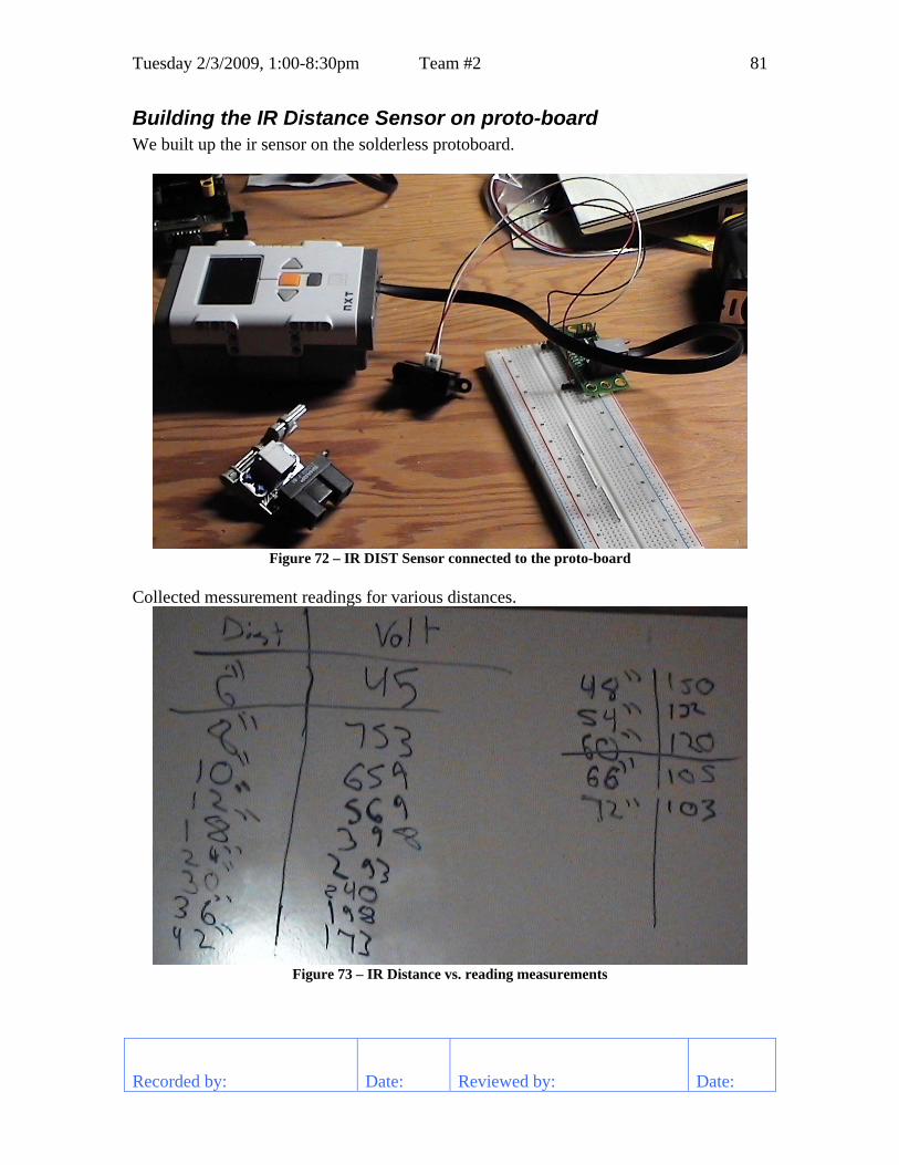
Tuesday 2/3/2009, 1:00-8:30pm Team #2 81
Recorded by: Date: Reviewed by: Date:
Building the IR Distance Sensor on proto-board We built up the ir sensor on the solderless protoboard.
Figure 72 – IR DIST Sensor connected to the proto-board
Collected messurement readings for various distances.
Figure 73 – IR Distance vs. reading measurements

82 Team #2 Tuesday 2/3/2009, 1:00-8:30pm
Recorded by: Date: Reviewed by: Date:
Converted this data into an equation using the “Linearizing IR Sensors” document by Sharp. The equation is:
Dist = ((1/Sensor) - .000136047)/.000136273 This sensor in our bread board seems to be rather noisy compared to the same sensor used in the distance sensor from Mindsensors. We placed an oscilloscope on the power supply and output leads in the sensor. The measurements of noise show that the power supply’s for the sensor and the Mindsenor one were about the same, but the output lead of ours was much worse.
Figure 74 – Oscilloscope trace of Power Supply and Signal Output Noise
After checking all the connections and adjusting all the wires the noise settled down. We don’t know exactly what made it go away. We’ll have to address this later.

Team #2 83
Recorded by: Date: Reviewed by: Date:
Friday 2/6/2009, 6:00-10:00pm Tasks Reflections Continue rebuilding robot. Finished the frame and arm support. It’s
taking a lot longer to build than expected.
Robot rebuild
Figure 75 – Rebuild with arm supports in and tool motor lower

Team #2 84
Recorded by: Date: Reviewed by: Date:
Sunday 2/8/2009, 2:00-5:00pm Tasks Reflections Continue IR Sensor Evaluation Determined that the NXT has enough
power to power all 4 sensors at once. The sensor sampling rate is around 40ms and proto-board can sample done to 10ms so we can use averaging to return more stable readings.
Continue rebuilding robot. Continued building the interior. Several elements were improved.
4.3 Volt Power Usage The NXT’s internal power supply can deliver 180ma to all sensor and motor ports. Since we aren’t using Lego motors and only connect the Motor Controllers and Compass Sensor, we need to measure the current of each of these devices and see what we can run.
Sensor Current Compass 8 ma Protoboard (empty) 3 ma Motor Controller < 1 ma Protoboard w/ 1 IR Sensor 29 ma
Table 5 – Sensor Current Usage With 4 IR Sensors the total supply draw is approximately 116ma. This is well under the 180ma limit, so we should be able to run all the sensors that we want.
Sensor Sampling Rate and Noisy Readings The IR Sensor produces a new reading about every 40ms. The protoboard is able to sample every 10ms. To improve noise we can average every 4 samples. We tested to see if all four sensors operate correctly together. The readings were very erratic. The power supply noise now approaches 1 V. We added a 100 uF capacitor across the power supply. Things worked much better, but we would still like to reduce it further.
Sensor Mounting Issues We need to mount a sensor pointing forward, but the bucket is in the way.
• Could be mounted on front near the tripper • See if we can cut a hole in the bucket that won’t let the pucks through. • Mount on side and narrow down the bucket.

Sunday 2/8/2009, 2:00-5:00pm Team #2 85
Recorded by: Date: Reviewed by: Date:
To see if we can cut a hole in the bucket, we checked to see how small a hole the sensor will operate through.
Figure 76 – Drawing of holes size required to IR Sensor to look through

86 Team #2 Sunday 2/8/2009, 2:00-5:00pm
Recorded by: Date: Reviewed by: Date:
Robot rebuild • Brace the tool motor to keep gears from slipping.
Figure 77 – Bracing Tool Motor Bracket
• Did the same thing for the drive motors. • Staggered the motor controllers so that we can get it all screw-in connectors.
Figure 78 – Staggered Motor Controllers

Team #2 87
Recorded by: Date: Reviewed by: Date:
Tuesday 2/10/2009, 5:00-9:00pm Tasks Reflections Continue Work on IR Sensor Board Designed and wired up most of the IR
Sensor board. The next step will be to build a case for the sensors and board.
Continue rebuilding robot. Base robot is mostly complete. We have to mount the NXT and redesign the bucket.
IR Sensor Board Contacted Gary Brown from Motorola on ways to improve the noisy readings that we are getting. He suggested using still larger capacitors on the power supply. Also, we should use an RC network on the signal line. Gary pointed me to an article on the web that explained RC circuits and how to use them to determine what we needed.
RC TIME CONSTANT
The time required to charge a capacitor to 63 percent (actually 63.2 percent) of full charge or to discharge it to 37 percent (actually 36.8 percent) of its initial voltage is known as the TIME CONSTANT (TC) of the circuit. The charge and discharge curves of a capacitor are shown in the figure below.
The value of the time constant in seconds is equal to the product of the circuit resistance in ohms and the circuit capacitance in farads. The value of one time constant is expressed mathematically as t = RC. Some forms of this formula used in calculating RC time constants are:
t (in seconds) = R (in ohms) X C (in farads) t (in seconds) = R (in megohms) X C (in microfarads) t (in microseconds) = R (in ohms) X C (in microfarads) t (in microseconds) = R (in megohms) X C (in picofarads)

88 Team #2 Tuesday 2/10/2009, 5:00-9:00pm
Recorded by: Date: Reviewed by: Date:
With this information we computed the RC values needed for the signal lines.
Figure 79 – Derivation of RC decoupling values
We added a 470uF capacitor across the power supply. This cleaned things up a lot more. We then added in our RC circuit in line with the sensor output and our readouts became a lot more stable.

Tuesday 2/10/2009, 5:00-9:00pm Team #2 89
Recorded by: Date: Reviewed by: Date:
Figure 80 – Schematic for Sensor Board
We then laid out the components and soldered up the prototype board.
Figure 81 – Prototype board ready to put the sensor cables on

90 Team #2 Tuesday 2/10/2009, 5:00-9:00pm
Recorded by: Date: Reviewed by: Date:
Robot Interior Continued work on the interior of the robot. Everything is connected except for the NXT. Getting this placed so that it is out of the way and we have easy access to all parts of it is difficult.
Figure 82 – Robot Interior after reconstruction
Compass Mount We mounted the compass sensor as far away from the motors as we could. The closest motor is 10” away now. We also shielded the sensor in case the robot tips over.
Figure 83 – Compass Sensor Mount

Team #2 91
Recorded by: Date: Reviewed by: Date:
Thursday 2/12/2009, 6:00-9:00pm Tasks Reflections Develop list of issues left to work on We have an initial cut at the number
remaining issues. This list will grow and change as we discover new things and get things fixed.
Work on IR Sensor mounting in robot A layout of sensor positions is done. Need to figure out how to mount them now.
Develop Bucket Prototype. We got a good start on the new design. The arms and tripper need to be worked on. Some work on balance is likely to be needed.
Issue List Number Description Hardware HW1 Move controllers forward to make it easier to plug in wires HW2 Motor and Servo Controller need support on both sides HW3 Side arms need to be angled so that sensors can see out HW4 Mount the NXT HW5 Use round headed screws on bottom to keep from catching on anything HW6 Consider wire tray for motor wires or possibly run down C channel in back HW7 Design arms to dump bucket HW8 Design new bucket HW9 Design new scoop HW10 Add flag pole HW11 Paint on team number and logo HW12 Mount sensors HW13 Hold down batteries with Velcro Auto SW ASW1 Debug simple auto straight program ASW2 Calibrate Compass ASW3 Develop auto programs for each starting position Tele SW TSW1 Add 4 speed gear shifting and optimize control
Table 6 – Issues list
IR Sensor Mounting

92 Team #2 Thursday 2/12/2009, 6:00-9:00pm
Recorded by: Date: Reviewed by: Date:
To be centered on the top rail, the sensors need to be mounted 10-3/4” high. The top railing is approximately 1-3/4” wide. The IR sensors need to be hitting this when we are in sensor range since the Lexan windows are transparent to this beam. The front sensor will have to pass through the bucket and the side sensors will force the lift arms to be bent. These three sensor are all at least 8” from the side of the robot so we can accurately detect right up to the wall. The back sensor is less than 8” from the robot so we need to be careful when using it.
Figure 84 – IR Sensor mounting scheme
Bucket Prototype We built a new bucket with a high front. The motor is strong enough to raise and dump over 30 pucks at a time. It will only need to hold a maximum of 26. The robot is a little unstable and the arms need to be adjusted.

Thursday 2/12/2009, 6:00-9:00pm Team #2 93
Recorded by: Date: Reviewed by: Date:
Figure 85 – Robot with new prototype bucket
Bugs Fixed • HW1 – move controller back • HW5 – use round headed screws

Team #2 94
Recorded by: Date: Reviewed by: Date:
Friday 2/13/2009, 7:30-9:00pm Tasks Reflections Debug simple straight auto program Found and fixed a few logic errors in using
the compass to turn the robot. Develop a means to calibrate the compass sensor
Discovered that the compass sensor has a total error of over 30 degrees. This is due to the strong magnets in the DC motors. It is difficult to move the compass any farther away from the motors so we need a way to calibrate this out.
Measuring Compass Error We used a turn table and marked lines every 15 degrees on it. The robot was placed on there and we measured the compass error at these intervals. Finally, excel was used to display a graph of the error.
Figure 86 – Robot on turn table for measuring compass error

Friday 2/13/2009, 7:30-9:00pm Team #2 95
Recorded by: Date: Reviewed by: Date:
Figure 87 – Graph of compass error
Algorithm for calibrating compass Need to develop an algorithm for removing the error in the compass. We decided to use piecewise linear approximation since there is not a lot of curve in the small segments on the data points.

96 Team #2 Friday 2/13/2009, 7:30-9:00pm
Recorded by: Date: Reviewed by: Date:
Figure 88 – Derivation of piecewise linear interpolation

Team #2 97
Recorded by: Date: Reviewed by: Date:
Saturday 2/14/2009, 12:00-6:00pm Tasks Reflections Write compass calibration software The software is written, but we still see
some readings that are around 5 degrees. Place rack tripper on robot We moved over the VEX tripper to the
robot bucket. It still needs more work, but initial test look good.
Work on mounting the distance sensors to the robot.
Have sensors mounted to a plate on the robot. Still need to mount the protoboard and finish wiring up the sensors.
Compass calibration software Wrote a simple compass sensor calibration routine to test out the calibration and then added it to the autonomous code.
#pragma config(Hubs, S1, HTMotor, HTMotor, HTServo, none) #pragma config(Sensor, S2,SENSOR_COMPASS, sensorI2CHiTechnicCompass) #pragma config(Motor, mtr_S1_C1_1, MOTOR_LEFT, tmotorNormal, openLoop) #pragma config(Motor, mtr_S1_C1_2, MOTOR_RIGHT, tmotorNormal, openLoop) #pragma config(Motor, mtr_S1_C2_1, MOTOR_TOOL, tmotorNormal, openLoop) #pragma config(Motor, mtr_S1_C2_2, , tmotorNone, openLoop) //*!!Code automatically generated by 'ROBOTC' configuration wizard !!*// short COMPASS_Data[26] = {-19, 0, 18, 37, 54, 68, 82, 95, 107, 120, 132, 144, 156, 168, 180, 191, 204, 217, 233, 248, 265, 281, 300, 321, 341, 360}; task main() { int x, y; int x0, x1, y0; int i; eraseDisplay(); while (true) { // display compass reading x = SensorValue[SENSOR_COMPASS]; // take compass reading nxtDisplayBigTextLine(2, " %03d", x); for(i=1; x > COMPASS_Data[i]; i++) // find location in calibration table ; // Convert reading to a calibrated value y0 = 15*(i-2); x1 = COMPASS_Data[i]; x0 = COMPASS_Data[i-1]; y = 15*(x-x0)/(x1-x0)+y0; // display calibrated reading nxtDisplayBigTextLine(4, " %03d", y); wait1Msec(15); } }
Listing 8 – Compass calibration routine

98 Team #2 Saturday 2/14/2009, 12:00-6:00pm
Recorded by: Date: Reviewed by: Date:
Rack Tripper
Figure 89 – Rack tripper mounted on robot
Distance Sensor Mounting
Figure 90 – Distance Sensor mounting
Bugs Fixed • HW10 – Add flag pole to robot • ASW2 – Added compass calibration to code

Team #2 99
Recorded by: Date: Reviewed by: Date:
Sunday 2/15/2009, 1:00-6:00pm Tasks Reflections Continue work on distance sensor mounting
Finished wiring up the protoboard and did a preliminary mount of the sensors.
Explore arm placement Careful arm placement and angles are essential. Exploration will continue at the next meeting.
Distance Sensor Finished wiring up the prototype board with the distance sensors. We got the scope out to see how clean everything was. We measured the power supply voltage at 4.4V with a 0.3V noise component. The signal lines were reasonable free of noise.
Figure 91 – Distance sensor power supply noise

100 Team #2 Sunday 2/15/2009, 1:00-6:00pm
Recorded by: Date: Reviewed by: Date:
Figure 92 – Signal noise
In doing a quick test to see if the distance sensor can just pick up the top rail of the wall showed that the sensor had to be precisely mounted. We will have to work on a way to improve the mounting.
Arm Placement Sorted out where the arms of the 4-bar linkage system need to mount to the ground. The top arm cannot move any higher that its current position to maintain our 18” clearance. Using convenient mounting points the lower arm will be located two holes below the top arm.

Team #2 101
Recorded by: Date: Reviewed by: Date:
Monday 2/16/2009, 12:00-6:00pm Tasks Reflections Calibrate the distance sensors With full loading on the NXT, calibrated
each distance sensor. We can now proceed with working on the autonomous programs.
Get 1st autonomous program fully working We only got started debugging this. Two problems in RobotC that convert integers and longs to floating points slowed us down.
Design the new arms for the robot. We have a paper design that looks good. In the process of building it now.
Distance Sensor Calibration
Figure 93 – Distance Sensor Calibration Setup

102 Team #2 Monday 2/16/2009, 12:00-6:00pm
Recorded by: Date: Reviewed by: Date:
Table 7 – Raw Distance Sensor Data

Monday 2/16/2009, 12:00-6:00pm Team #2 103
Recorded by: Date: Reviewed by: Date:
Figure 94 – Graph of normal and inverse sensor data
Figure 95 – Sensor Calibration Equations

104 Team #2 Monday 2/16/2009, 12:00-6:00pm
Recorded by: Date: Reviewed by: Date:
Robot Arm Using the 4-bar linkage design procedure, designed the linkages to the new arm placement.
Figure 96 – Arm 4-bar linkage design

Team #2 105
Recorded by: Date: Reviewed by: Date:
Tuesday 2/17/2009, 6:00-9:00pm Tasks Reflections Get 1st autonomous program fully working Found some issues with RobotC not
converting data correctly, the erratic behavior is still there.
Design the new arms for the robot. Have the bent side arms designed. Need to work on the center arm for next meeting.
Autonomous It’s taking a long time to sort out why the program is behaving very erratic. We found out that RobotC doesn’t always evaluate expressions correctly. Where we think there will be problems, we assign intermediate results to variables. This helps some times.
Arm Design With the new arm dimensions designed, we have built the side arms. We hope this design works as well as the way it looks on paper.
Bugs Fixed HW7 – Arms designed for new positions

Team #2 106
Recorded by: Date: Reviewed by: Date:
Thursday 2/19/2009, 6:00-10:00pm Tasks Reflections Adjust Tele-op controls to be more responsive.
Added a high and low gear virtual gear. After tweaking, the control feels good.
Get 1st autonomous program fully working Still having problems. Can’t figure out why the position information keeps jumping around. Top priority for next meeting.
Design the new arms for the robot. Finished the center arm design. We are now ready to design the bucket.
Tele-op Controls We use feedback to try to keep the robot speed to match the joystick setting. This was difficult to do as just one gear. Added 2 other gears and adjusted the feedback and now the robot controls much easier.
Autonomous Still having problems. We are learning a lot about the dos and don’ts with RobotC.
• Type conversion in expression don’t always work • Complicated expressions don’t evaluate correctly, need to keep them simple • Breakpoints are only recognized if the file containing them is the window that is
open • The pragma that auto-starts tasks, start all of them. It is in joystickDriver.c. We
don’t want all our tasks to start up at once.
Arm Design Finished the design. And are ready to move on to the bucket.
Figure 97 – Robot with new arm design

Thursday 2/19/2009, 6:00-10:00pm Team #2 107
Recorded by: Date: Reviewed by: Date:
Bucket Design We want a simple box design to hold the pucks. The dimensions are big enough to hold 3 racks of pucks.
Figure 98 – Dimensions for Bucket
Bugs Fixed HW3 – Design angled side arms so that the sensors can see out.

Team #2 108
Recorded by: Date: Reviewed by: Date:
Friday 2/20/2009, 4:00-11:00pm Tasks Reflections Get 1st autonomous program fully working We’re finally there. Found a problem in
one routine and a couple of issues with robotC.
Design the bucket for the robot. The design is complete, we will finish building it at the next meeting.
Rebuild the sensor bay so that the sensor height is adjustable.
We have an adjustable design for the sensors, we will finish at the next meeting.
Autonomous We discovered one logic error and two RobotC evaluation issues and now the simple code runs.
Bucket The metal for the bottom and back was bent. This was very difficult and required the help of the coach to get right. The polycarbonate for the back has been cut and bolted on. We need to shape the sides to make a shute.
Figure 99 – Partial bucket on Robot

Friday 2/20/2009, 4:00-11:00pm Team #2 109
Recorded by: Date: Reviewed by: Date:
Sensor Bay Redesigned the sensor mounting so that we can adjust their height easily. This involved using a screw with a nylock nut to hold it in-place on the plate.
Figure 100 – Adjustable sensor mounting design
Bugs Fixed HW2 – provided support for both sides of the motor and servo controller. HW8 – design scoop is put on hold, because we are out of time. By doing this, we could potentially give up 30 to 40 points a match if the other alliance decides to dump our pucks. ASW1 – Finally have the simple straight autonomous program running.

Team #2 110
Recorded by: Date: Reviewed by: Date:
Saturday 2/21/2009, 9:00am-11:00pm Tasks Reflections Review the remaining issues A lot of the issues wee resolved. The only
important one left was the autonomous control.
Continue Autonomous Programming We are continuously running into very erratic and seemingly random behavior. We will have to live with this at the tournament.
Mount sensor module Done, we just implemented it between the robot arms for protection.
Finish Bucket Design We formed our first polycarbonate pieces today. With more practice we can do a much better job. What we have should work at the tournament.
Design Tripper Redesigned the tripper out of Tetrix parts. It is a little smaller and looks more elegant that the original.
Issue List Number Description Hardware HW4 Mount the NXT HW6 Consider wire tray for motor wires or possibly run down C channel in back HW8 Design new bucket HW9 Design new scoop (on hold) HW11 Paint on team number and logo HW12 Mount sensors HW13 Hold down batteries with Velcro Auto SW ASW3 Develop auto programs for each starting position Tele SW TSW2 Move arm controls to second joystick controller TSW3 Add a speed control for the arm.
Table 8 – Issues list

Saturday 2/21/2009, 9:00am-11:00pm Team #2 111
Recorded by: Date: Reviewed by: Date:
Mount NXT and Sensors
Figure 101 – NXT Mounting with Sensors
Finish Bucket Design
Figure 102 – New Bucket Design

112 Team #2 Saturday 2/21/2009, 9:00am-11:00pm
Recorded by: Date: Reviewed by: Date:
Design Tripper
Figure 103 – Tetrix Tripper Design
Autonomous Software The compass sensor was giving some erratic results so we moved it further away from the NXT and motors. The mounting place there was smaller, so we redesigned the way the compass is mounted. We drilled and tapped a stand-off and mounted the sensor to it. This took a lot less space than using LEGOs. As we worked the autonomous code kept behaving very erratically. The initial forward movement would sometimes only go half the distance and others would well overshoot. Sometimes the robot would know that it didn’t go the right distance and sometimes it wouldn’t. We are out of time and are going to live with what we have.

Saturday 2/21/2009, 9:00am-11:00pm Team #2 113
Recorded by: Date: Reviewed by: Date:
Figure 104 – Modified Compass Sensor Mount
Bugs Fixed HW4 – Mount the NXT. HW8 – Design New Bucket HW12 – Mount Sensors HW13 – Hold down batteries with Velcro TSW2 – Move arm controls to second joystick TSW3 – Add speed control for the arm

Team #2 114
Recorded by: Date: Reviewed by: Date:
Sunday 3/1/2009, 1:00-4:00pm Tasks Reflections Review issues found at the tournament Identified the major work left. We will get
started next meeting.. Prioritize remaining tasks The hardware is pretty good shape.
Adding a puck pickup device is the only major work desired. The autonomous software still needs a lot of work.
Make travel arrangements to Atlanta We all searched for airline flights and hotels and finally settled on ones.
Hardware Issues
Figure 105 – Hardware to-do list

Sunday 3/1/2009, 1:00-4:00pm Team #2 115
Recorded by: Date: Reviewed by: Date:
Figure 106 – Robot Balance and Puck Pickup
Figure 107 – Combine idea for puck pick-up

116 Team #2 Sunday 3/1/2009, 1:00-4:00pm
Recorded by: Date: Reviewed by: Date:
Software issues
Figure 108 – Programming Issues List

Team #2 117
Recorded by: Date: Reviewed by: Date:
Thursday 3/5/2009, 6:00-8:00pm Tasks Reflections Start work on the remaining hardware issues.
.Put pan head screws inside bucket to keep pucks from getting stuck. Re-measured the puck tripper for the updated design.
Pucks getting stuck in the bucket Pucks were getting hung up on the nuts inside the bucket. We used pan head bolts and turned them around so that the nuts were on the outside. The upper left side of the bucket is a little narrow and sometimes the pucks still get stuck. We will work on this later.
Tripper Started work on the new tripper design. The dimensions of the old one didn’t trip the racks always and blocked the pucks from easily going into the bucket.
Figure 109 – New tripper design

Team #2 118
Recorded by: Date: Reviewed by: Date:
Sunday 3/8/2009, 1:00-5:00pm Tasks Reflections Work on finding the causes of erratic software issues.
We have found two major issues. We are able to focus on our problems now.
Continue tripper design. .Work is progressing slowly, but the new design looks promising.
Erratic Software 1. The compass sensor does not always give valid results. We will have to test each
value and see if it is reasonable before we use it. The compass should not change by more than a few degrees between readings. We will use this knowledge to test for valid readings.
2. Only a single task may call a function. RobotC doesn’t always detect this. We are making sure that only single tasks call any function.
Tripper Identified the new pieces to be cut. Will cut them at next meeting. Need a rectangular piece to stabilize the side-to-side movement of the tripper. Need a couple of vertical pieces to support the trip mechanism so that it will get out of the way of the pucks as they fall.

Team #2 119
Recorded by: Date: Reviewed by: Date:
Thursday 3/12/2009, 6:00-8:00pm Tasks Reflections Study robot tipping issues. The CG is a little higher than we like but
the robot is stable in normal driving mode and is able to successfully travel down the ramp without tipping over. The best thing to do now is nothing. Just need to make sure that something is behind us when raising the bucket.
Robot Stability We measured the center of gravity by finding the balance point horizontally and vertically.
Figure 110 – Robot center of gravity

Team #2 120
Recorded by: Date: Reviewed by: Date:
Sunday 3/15/2009, 1:00-6:00pm Tasks Reflections Review issues left to solve Reviewed and added a few of the most
pressing for software. Continue autonomous software work. Worked on getting the robot down the
ramp. Then next step is to locate our self after reaching the mat. Spent time testing the performance of the distance sensor with the actual arena rails. Need to do more work as the reliability needs to be better. Started using data logging to better understand what the robot is doing. This should help us fix problems much faster.
Finish tripper design. Finally finished it. It seems to work very well.
Fix gear slippage problem on lift arm. Doubled up on the shaft collars to fix the slippage.
Issue List Number Description Hardware HW6 Consider wire tray for motor wires or possibly run down C channel in back HW9 Design new scoop HW11 Paint on team number and logo HW14 Design tripper to quickly release pucks from rack HW15 Gears slip on lift arm. HW16 Work on puck pickup mechanism Auto SW ASW3 Develop working auto programs for each starting position ASW4 Get robot off ramp reliably ASW5 Score two puck racks ASW6 Program for multiple paths (avoidance) ASW7 Drive straight with compass sensor and stop accurately. Tele SW TSW4 Fix low speed control, as robot got heavier this got faster
Table 9 – Issues list

Sunday 3/15/2009, 1:00-6:00pm Team #2 121
Recorded by: Date: Reviewed by: Date:
Compass Sensor The compass sensor suddenly quit giving good readings. We replaced it with a new one and the problem was solved. This may have been the cause of the erratic readings that we were seeing at the state tournament.
Autonomous Software Wrote some simple test software to get robot down off ramp. Running at power level 30 and cutting back to 10 or coasting down the ramp works fine. Higher powers can dump the robot as it hits the bottom. The next step is to determine our location after we reach the bottom of the ramp. Driving forward using the compass sensor does not reliably stop at the desired distance. We have started using the data logging feature of RobotC to capture data and analyze it in Excel.
Distance Sensors In testing the distance sensor using the actual competition rails, the reliability drops off. It is difficult to get them pointed at the rails at 4 feet and beyond. We have ordered an IR camera to help determine where they are actually pointed. The sensors are still useful close up and we may have to rely more on dead reckoning than we originally wanted to.
Tripper Brought the last pieces together. It works great.
Figure 111 – Finished tripper design

122 Team #2 Sunday 3/15/2009, 1:00-6:00pm
Recorded by: Date: Reviewed by: Date:
Gear Slippage To fix the gear slippage on the arm shaft, we doubled up on the gear collars. This should fix the slippage problem. There still is a concern if the shaft will bend under the load.
Figure 112 – Double collars on gears to stop slipping
Bugs Fixed HW14 – Design tripper to quickly release pucks HW15 – Gears slip on lift arm shaft.

Team #2 123
Recorded by: Date: Reviewed by: Date:
Tuesday 3/17/2009, 7:00-10:00pm Tasks Reflections Continue debug of autonomous code Got data logging to work and can capture
significant portions of a run and use excel to analyze the results. We will continue to heavily use this code as it is very useful.
Capturing the Data Log Added the following code to our autonomous program to capture a data log.
task main() … nDatalogSize = 10000; nMaxDataFileSize = 100; …
SaveNxtDatalog();
task FIELDLOC_Update() { … while(true) { … AddToDatalog(0, FIELDLOC_Position.currentLoc.x); AddToDatalog(1, FIELDLOC_Position.currentLoc.y); AddToDatalog(2, FIELDLOC_Position.currentLoc.angle); AddToDatalog(3, FIELDLOC_Position.currentIRDist.front); AddToDatalog(4, FIELDLOC_Position.currentIRDist.left); AddToDatalog(5, FIELDLOC_Position.currentIRDist.right); AddToDatalog(6, FIELDLOC_Position.currentIRDist.back); AddToDatalog(7, FIELDLOC_Position.currentRot.left); AddToDatalog(8, FIELDLOC_Position.currentRot.right); }
Listing 9 – Code to capture data to data log

124 Team #2 Tuesday 3/17/2009, 7:00-10:00pm
Recorded by: Date: Reviewed by: Date:
To import this data into an excel spreadsheet, we wrote our own conversion program as the one in RobotC didn’t do what we wanted.
/*************************************************************************** This program converts the binary data log from the NXT to a comma separated value (CSV) file for import to excel for analysis. This program keys off the index value in the data log to determine how many values to insert on a row. This differs from the robotC version which only puts one data value per row. To run the program, type ConvertLogToCSV inputFileName outputFileName ****************************************************************************/ #include <stdio.h> int main(int argc, char *argv[]) { unsigned char cbuf[10]; FILE *infile, *outfile; short value; int newRowId; int numElements; int i; if (argc < 3) { printf("usage: %s inputFileName outputFileName\n", argv[0]); return(0); } if ((infile = fopen(argv[1], "rb")) == NULL) { printf("error in opening inputFile: %s\n", argv[1]); return(1); } if ((outfile = fopen(argv[2], "w")) == NULL) { printf("error to open outputFile: %s\n", argv[2]); return(1); } // Skip over header information if (fread(cbuf, 1, 8, infile) != 8) { printf("Can't read input header\n"); return(1); } // Read and process the number of elements if (fread(cbuf, 1, 3, infile) != 3) { printf("Can't read number of data elements\n"); return(1); } if (cbuf[0] != 255) { printf("Invalid data format\n"); return(1); } numElements = (cbuf[2] << 8) | cbuf[1]; // Process the first element if (fread(cbuf, 1, 3, infile) != 3) { printf("Can't read 1st data element\n"); return(1);

Tuesday 3/17/2009, 7:00-10:00pm Team #2 125
Recorded by: Date: Reviewed by: Date:
} newRowId = cbuf[0]; value = (cbuf[2] << 8) | cbuf[1]; fprintf(outfile, " %d", value); for (i = 2; i < numElements; i++) { // Process the first element if (fread(cbuf, 1, 3, infile) != 3) { printf("Can't read data element %d of %d\n", i, numElements); return(1); } value = (cbuf[2] << 8) | cbuf[1]; if (cbuf[0] == newRowId) { fprintf(outfile, "\n %d", value); } else { fprintf(outfile, ", %d", value); } } fflush(outfile); fclose(infile); fclose(outfile); return(0); }
Listing 10 – Program to convert Data Log to CSV file
Data Log Analysis The following graph shows the first capture we made.
Figure 113 – Datalog analysis of autonomous
There were several things that we discovered about the software and sensors.
1. Initial robot coordinates were incorrect. 2. When distance sensors were used to determine the position, the state was not
saved and when they weren’t used, the position reverted back to the rotation sensor position calculation.
3. At close distance the distance sensor sometimes misses the top arena rail. 4. Get erratic back sensor readings when shooting under the ramp. 5. When turning the Y position calculation is off.

Team #2 126
Recorded by: Date: Reviewed by: Date:
Thursday 3/19/2009, 7:00-9:00pm Tasks Reflections Work on picking up pucks off mat. Got a good start in prototyping a dual
pickup wheel. Continue autonomous software Stalled by compass sensor problems. We
need to explore a solution to this in order to effectively more forward.
Tele-op Practice This was our first real practice session. We never had time to do one before state. Several problems were identified.
Picking pucks off mat We started work on using a dual wheel approach to see how well it will pick the pucks off the mat. We are prototyping in Vex since we have a variety of parts to work with.
Figure 114 – Beginnings of Dual Wheel Puck Pickup

Thursday 3/19/2009, 7:00-9:00pm Team #2 127
Recorded by: Date: Reviewed by: Date:
Compass Errors The compass sensor seemed to have a few degrees of error shortly after we calibrated it. We carried out a test by placing the robot at various locations on the field aligned with the floor mats. We found an 11° difference. We should have carried out this test long ago. We did not expect this kind of localized error. We need to look at options to fix this:
• Rely on distance sensors to somehow correct for our angle as well as position. We are not sure how to really accomplish this. Plus the distance sensors are not as reliable as we would like anyway.
• Could use the gyroscope or acceleration sensor to replace the compass. We have no experience with these and don’t have any idea how well they could be made to work.
• Mount a light sensor to follow the lines on the mat and scale back our autonomous efforts.
• The least attractive thing to do is to just use dead-reckoning in autonomous.
Tele-op Practice We did our first serious tele-op practice. We need to practice a lot more to become proficient. We discovered a few issues that need addressing.
• Robot tips over when coming down ramp. It didn’t do this in autonomous mode, but driver skill is important. We may need to find a way to lower the center of gravity some more.
• We bent the joints of the robot arms. We need to make them stronger and add some more screws.
• The rack tripper still needs some more work. We have to be very straight in order for it to work and the rack must be hit harder than we anticipated.
• Motors get hot after several minutes of running around. We need to measure how hot they get and how fast we can cool them down. We can test using ice packs between matches to see if this will be sufficient. We may also have to be careful during a match to minimize conditions that will heat them up.

Team #2 128
Recorded by: Date: Reviewed by: Date:
Sunday 3/22/2009, 1:00-7:00pm Tasks Reflections Continue autonomous software After firmly securing the ramp, we
discovered we still fall over going down it. Did some work with dead reckoning to help compensate for the compass errors we were seeing. We still have much more work to do here. We developed a algorithm to keep the rotation sensor counts in sync with updating position with the IR sensor.
Fix hardware issues Acquired an IR camera and can now observe where the IR sensor is aimed. Cut a hole in the bucket to let the front sensor see out.
Getting off the ramp in autonomous We wanted to finish this software task so we can move on to the next steps. We discovered that our robot is simply just not stable coming down the ramp. Before, the platform and ramp was not solidly secured allowing the platform to tip slightly and make it easier to come down the ramp. With the platform fixed, we tip over.
Figure 115 – robot tipping over coming down ramp

Sunday 3/22/2009, 1:00-7:00pm Team #2 129
Recorded by: Date: Reviewed by: Date:
We tried several things to help this: • If we apply brakes when were coming down, we made the problem worse, it
tipped over for sure. • We start slowly at the top then coast at a low power level. The problem with this
is having sufficient to power to get moving while we are on the ramp. • We also tried high power near the end of the ramp. This worked sometimes, but
was difficult to get consistent results though. We need to spend more time on this.
Working around compass sensor accuracy Dead reckoning when going straight seems to be more accurate then when we are using the compass sensor. We also worked on a algorithm to measure the change in both left and right rotation sensors as to compute an angle change. We still need more work on this to know when we should use it over the compass sensor.
Turning using rotation sensors Since we don’t know the exact angle to turn to, we wanted to see how accurate we can turn with the rotation sensors. Knowing the distance between the wheels, we derived the equation for turning.
Figure 116 – deriving equations for rotation sensor turning Test showed there is a little more variability then we would hope for. It is similar to the amount of compass error we now have.

130 Team #2 Sunday 3/22/2009, 1:00-7:00pm
Recorded by: Date: Reviewed by: Date:
IR distance sensor position correction When we detect we have a good reading with our distance sensor we need to adjust our position without losing accuracy from the rotation sensors. In the case of the Y direction having a good reading we simply compare this with the computed Y value then adjust the reference Y value by the difference.
Figure 117 – adjusting rotational reference
The same can be done for the X direction.
Letting the front IR sensor see out We finally got around to cutting a hole in the bucket so the IR sensor can see out.
Figure 118 – IR sensor hole

Sunday 3/22/2009, 1:00-7:00pm Team #2 131
Recorded by: Date: Reviewed by: Date:
Positioning the IR sensor It has been difficult knowing what the sensor sees when we get bad readings. We acquired an IR camera and can now see where the sensors’ spot is. This should greatly help us adjust things.
Figure 119 – Using the IR camera to find sensor spot

Team #2 132
Recorded by: Date: Reviewed by: Date:
Tuesday 3/24/2009, 6:00-8:00pm Tasks Reflections Work on picking up pucks off mat. Made some progress. The procedure we
are using still looks promising. Autonomous software development Uneven data sampling is a major problem
in us being able to precisely control the robot. Two issues have been identified that need fixing. The prototype board locks the cpu for 4msec when sending a message and we need to combine the use of the timer with the wait function to control the task sampling rates.
Picking Pucks off the Mat Continued exploration of automatically picking up the pucks. Moved from using the feeder wheels to the small Vex wheels. They grip the pucks a little better. The next step is to get the spacing of the wheels correct to see how effectively we can get the pucks.
Getting Consistent Measurements In measuring the autonomous performance we keep getting a high variability in our measurements. These include such basic things as our sampling of the rotation sensors. Being able to get consistent readings should help with designing the rest of our routines. We discovered that in the I2CSendMsg for the protoboard, stalls the system for up to 4 msec. This is an intrinsic so it may be difficult to work around. This will be a topic for the next meeting. If a task takes a little longer than expected then the wait1Msec function still delays the same amount of time. We need to change this so that when it takes longer to do something the wait is less. A timer should help us do this. We will look to implement this at the next meeting. The main task and the updateLocation task are not synchronized. Doing so will help reduce some of the variability of the system. We should be able to do this with some kind of signaling.

Team #2 133
Recorded by: Date: Reviewed by: Date:
Thursday 3/26/2009, 6:00-9:00pm Tasks Reflections Work on picking up pucks off mat. Made some progress. We will spend
another meeting on this to see if we can make it work for the tournament.
Run I2cSendMsg in background Had to lower the priority of the protoboard driver. There didn’t seem to be any other way to get I2CSendMsg to not hog the cpu.
Run sampling tasks at even intervals Running the sampling at even intervals makes it easier to get reliable results. We can make it all run this way except the HiTechnic Motor Controller, which is probably the most important to do.
Synchronize critical tasks Synchronize the main and updateLocation Tasks. This cuts out up to a 13msec jitter in our decision making.
Running I2CSendMsg in background We tried to change how I2CSendMsg operated by trying to not have it wait for the return message to be received, since it is a long message and takes about 3msec. This messaging only needs to run in our protoboard driver. Since the update of the IR Sensors is around 50msec and much slower than anything else we do, having it run at al low priority doesn’t hurt us much.
Getting Tasks to run at even intervals To make the tasks run at even intervals, we use one of the timers along with wait1MSec function. The following code shows how we did this for the updateLocation Task.
while(true) {
timeSample = time1[T1]; // get the time for this data sample FIELDLOC_UpdateOld(); FIELDLOC_UpdateCurrent(); dataReady = 1; // show new sample acquired
// adjust the wait time for processing time wait1Msec(13 - (time1[T1] - timeSample));
} Listing 11 – Code to generate even data samples
Synchronizing main and updateLocation Tasks We used a global variable to communicate between the tasks. The update task sets this when it reads new data. The main tasks then polls this variable to see when it is set before doing anything else. This replaces the wait the we were using. The main task calls the following function:

134 Team #2 Thursday 3/26/2009, 6:00-9:00pm
Recorded by: Date: Reviewed by: Date:
int dataReady = 0; void waitForDataReady() { while(true) { if(dataReady == 1) { dataReady = 0; break; } wait1Msec(1); } }
Listing 12 – Function to synchronize Tasks
Picking Pucks off the Mat Experimented with adding zip ties to the pickup wheels to help get the pucks off the mat. It does a pretty good job now. The next step is to get the wheel spacing right so that it is very consistent.
Figure 120 – Puck Pickup Development

Team #2 135
Recorded by: Date: Reviewed by: Date:
Sunday 3/29/2009, 1:00-6:00pm Tasks Reflections Decide on puck pickup task. Although the method being developed
looks very promising, it is going to take too long to finish and could have a negative effect on robot balance so we are not going to persue this any further.
Work on Compass Sensor Errors (again) We are going to minimize the use of the compass sensor in favor of the gyro sensor. The gyro produces much better results over the short term than the compass.
Review remaining hardware issues We have quite a few problems left to resolve, but they are all small and should be easy to resolve.
Puck Pickup on Mat It will take at least two more meetings to get a VEX prototype working to pick up the pucks. They we will have to come up with a design that uses competition allowed parts and integrate it in with the bucket. This could make the bucket too heavy and possibly put too much weight forward on the robot. To stand a chance of getting this completed will take working several hours every night. This is something that we do not have time for. We are going to put this effort on hold and focus on getting the rest of the robot in the best shape it can be.
Compass Sensor Errors The basic issues in using the compass sensor are:
• Local magnetic field changes by many degrees over the playing field. We can’t expect that they will be better at a competition.
• The metal railing impacts the compass reading by about 3 degrees when within about 6 inches. Since there is more metal in the joints of the railing, that affect the reading even more.
• Calibrating out the effects of the motors on the compass sensor don’t allow us to correct for field differences.
The only thing that we can reliably use the compass sensor for is in determining the general direction (with possible several degree error). I trying to accomplish precise turns using the rotation sensors does not give reliable results either. They seem to be a little bit better than using the compass sensor.

136 Team #2 Sunday 3/29/2009, 1:00-6:00pm
Recorded by: Date: Reviewed by: Date:
We have an unused input port on the NXT, so we are going to evaluate the gyroscope sensor. We started with the example GyroDriver code. It looks like we can achieve better results for turns by using this over our other methods. The sensor drifts quite a bit over time, but for doing turns it appears stable enough.
Hardware Issues List Number Description Hardware HW6 Redress the wires, consider running inside C-channel HW9 Redo bucket (re-bend materials) HW11 Paint on team number and logo HW14 Design tripper to quickly release pucks from rack (again) HW15 Gears slip on lift arm (Need to make sure latest fix doesn’t work loose) HW16 Work on puck pickup mechanism HW17 Redo robot interior (controller and batteries) HW18 Find different place for flag (can cover IR sensor) HW19 Locktite all bolts HW20 Deal with bending and stress in arm bars HW21 Optional: make motors more accessible (for quickly cooling between matches)Auto SW ASW3 Develop working auto programs for each starting position ASW4 Get robot off ramp reliably ASW5 Score two puck racks ASW6 Program for multiple paths (avoidance) ASW7 Drive straight with compass sensor and stop accurately. Tele SW TSW5 Speed up low speed turning
Table 10 – Issues list
Redo Robot Interior Since we no longer need a servo controller, we have additional space inside the robot. We moved the batteries further back in the robot and removed some unneeded hardware.

Sunday 3/29/2009, 1:00-6:00pm Team #2 137
Recorded by: Date: Reviewed by: Date:
Figure 121 – Updated Robot Interior
Flag Holder Relocation The flag was able to swing around and cover the rear IR sensors. It was moved up and more to the interior.
Figure 122 – Flag Holder Mounting

Team #2 138
Recorded by: Date: Reviewed by: Date:
Tuesday 3/31/2009, 6:00-8:00pm Tasks Reflections Work on Rack Tripper. Shortened up the tripper to give additional
space for turning. This didn’t work too well. We need the length to more easily dump the pucks.
Work on improving performance for small turns
Tried pulsing the motors to get more precise turning. We got very jerky action that still caused the robot to move too far.
Puck Tripper Moved the attachments to the back of the catch mechanism to give more turning space. We just had enough space to dump the puck when going straight into the rack. At an angle we couldn’t dump them. We can move the pivot point forward again with bent arm attaching behind the catch to make it work better.
Figure 123 – Failed Tripper Mod
Small Angle Turning We tried pulsing the motors to be able to more precisely stop at the desired point. This gave the robot a jerky response and it still varied as must as 5 degrees in the stopping location. We need better precision than this, so we have more work to do.

Team #2 139
Recorded by: Date: Reviewed by: Date:
Thursday 4/02/2009, 6:00-9:00pm Tasks Reflections Work on Rack Tripper. Designed and cut new brackets. Will drill
and try them out next meeting. Work on Logo and Team Number for the robot.
Tried etching the polycarbonate, but at a distance it does not show up. Adding paint masked the etching effect. We will probably do something similar to last years robot, because it looks good at a distance.
Work on improving performance for small turns
Found a bug in the pulsing code. Performance improved a lot, but it is still not good enough. We need to keep exploring
Puck Tripper We needed to move the position of the tripper back to the original position, but still leave room so the robot can turn into the rack. Designing special arms for the tripper should accomplish this.
Figure 124 – Sketch of new tripper arms
WE got the arms cut and bent from aluminum sheeting. We need to drill the holes and mount them at the next meeting.

140 Team #2 Thursday 4/02/2009, 6:00-9:00pm
Recorded by: Date: Reviewed by: Date:
Figure 125 – Tripper arm Pieces
Robot Logo We wanted to try something different to display the team Logo on the robot. Etching the polycarbonate seemed like something good to try. The Logo looks good up close, but not at a distance. All the detail is lost. We tried adding paint, but the etching effect is lost.
Figure 126 – Etched Logo in Polycarb

Thursday 4/02/2009, 6:00-9:00pm Team #2 141
Recorded by: Date: Reviewed by: Date:
Figure 127 – Hand painting conceals the etching effects
Autonomous Small Turns We expected that pulsing the motors would yield better results than it did. We found a bug in delays between the pulses. This improved things a lot, but the performance is still net there. Next meeting we will lot at doing something similar to how we handle slow turns in tele-op mode.

Team #2 142
Recorded by: Date: Reviewed by: Date:
Sunday 4/05/2009, 1:00-5:00pm Tasks Reflections Work on Rack Tripper. New tripper works very well. Still have to
finish rubber band attachment and the stop. Work on Logo and Team Number for the robot.
We decided to stay with the log that we had. It shows up well at a distance.
Work on improving performance for small turns
We analyzed the start up and stop times of the system as are able to finally get okay control for small turns.
Tripper Design Finally have the tripper reconnected. We still have to attach a proper stop and adjust the rubber band. It works very well.
Figure 128 – Almost completed tripper design
Logo We want to look at trying three things to improve the looks of the logo:
• Try printing on transparency to remove the white background. If the team number is visible enough, we could possibly use that.
• Try printing on gray paper, so the background more closely matches the metal on the robot.
• Place a big strawberry on the front of the robot. We printed our logo on a transparency and gray paper. Of these choices, the white background still is preferred. We really like the transparent nature of the bucket. Putting

Sunday 4/05/2009, 1:00-5:00pm Team #2 143
Recorded by: Date: Reviewed by: Date:
a big strawberry on the front obscures this. The final decision is to go with what we had before, logo on a white background. We need to get some plastic sheeting to protect the logo from damage.
Small Turn Control After running some test on the start and stopping of the motors while turning, we discovered the following:
• It takes 4 samples after setting the motor power before we see the rotation sensors start to move.
• After about 18 samples we have turned 1 degree. This is independent if the power is at 70 or 100%. It takes another 3 samples before we have turned another degree.
• After the robot starts turning then speed is very dependent on the power levels. • If the motors stay on very long, it takes a long time to get the robot stopped. If we
turn them off shortly after the robot starts turning, we can get small turns.
task main() { int timeSample; int lastTime; int dir; int TTA_diff, TTA_lastDiff; int TTA_stallCount = 0; int speed, powerBase; int r_last, r_enc, r_diff; int l_last, l_enc, l_diff; int rPower, lPower; int loopCount = 0; nDatalogSize = 10000; nMaxDataFileSize = 100; time1[T1] = 0; initializeRobot(); // Initialize for the turn GYRO_SetAngle(0); r_last = nMotorEncoder[MOTOR_RIGHT]; l_last = -nMotorEncoder[MOTOR_LEFT]; while (true) { timeSample = time1[T1]; //grab the current time // determine how far we have left to go dir = GYRO_GetAngle(); TTA_diff = COMPASS_HeadingError(15, dir); // Compute how speed of each wheel r_enc = nMotorEncoder[MOTOR_RIGHT]; r_diff = r_enc - r_last; r_last = r_enc; l_enc = -nMotorEncoder[MOTOR_LEFT]; l_diff = l_enc - l_last; l_last = l_enc;

144 Team #2 Sunday 4/05/2009, 1:00-5:00pm
Recorded by: Date: Reviewed by: Date:
// If we have a long way to go and are starting up // use high motor power if (TTA_diff < -40 && loopCount < 30) { rPower = -80; lPower = 80; } // Nearing the end, so use reduced power else if (TTA_diff < 0) { rPower = -50; lPower = 50; } // At the end, stop motors and wait for robot to stop else { rPower = 0; lPower = 0; if (TTA_lastDiff == TTA_diff) break; } motor[MOTOR_RIGHT] = rPower; motor[MOTOR_LEFT] = lPower; // Check to see if robot has stalled, if so stop robot and quit if(TTA_lastDiff - TTA_diff == 0) { TTA_stallCount++; if(TTA_stallCount > 38) { // Robot has stalled out, time to stop break; } } else { TTA_stallCount = 0; } TTA_lastDiff = TTA_diff; // Save information to datalog AddToDatalog(0, TTA_diff); AddToDatalog(1, r_diff); AddToDatalog(2, l_diff); AddToDatalog(3, rPower); loopCount++; lastTime = timeSample; wait1Msec(13 - (time1[T1] - timeSample)); } // Make sure motors are stopped and write datalog motor[MOTOR_RIGHT] = 0; motor[MOTOR_LEFT] = 0; SaveNxtDatalog(); }
Listing 13 – Turning Test Routine

Sunday 4/05/2009, 1:00-5:00pm Team #2 145
Recorded by: Date: Reviewed by: Date:
Figure 129 – Graph of 90 degree turn test
Figure 130 – Graph of 15 degree turn test

Team #2 146
Recorded by: Date: Reviewed by: Date:
Tuesday 4/07/2009, 5:00-9:30pm Tasks Reflections Get basic autonomous ground level routines running
Had a DC drive motor failure, so we didn’t have much time to work on auto before the scrimmage. At the scrimmage we captured some data on robot performance so we could analyze it later.
Scrimmage with two other teams going to Atlanta.
Spent 2-1/2 hours scrimmaging and working on the robot. The field that we were on seemed to give the robot different behavior that ours. The mats are the same, the only things is that they are directly on a concrete floor where ours sits on a hardwood floor over concrete.
DC Motor Failure The right drive motor slowly failed. The first evidence was the robot was not slowing down normally and a ½ hour later, it completely died. Swapping it out took about 20 minutes.
Scrimmage The biggest thing we noticed right away was that our autonomous modes all worked differently. We use feedback and sensors to control our movements, but turning especially seemed to overshoot a lot. Once we re-tweaked this in, everything ran as usual. We captured some data logs and graphed the robots movements in excel.

Tuesday 4/07/2009, 5:00-9:30pm Team #2 147
Recorded by: Date: Reviewed by: Date:
Figure 131 – Graph of captured variables for Red Ground Run
Figure 132 – Red Ground X, Y position showing computation errors
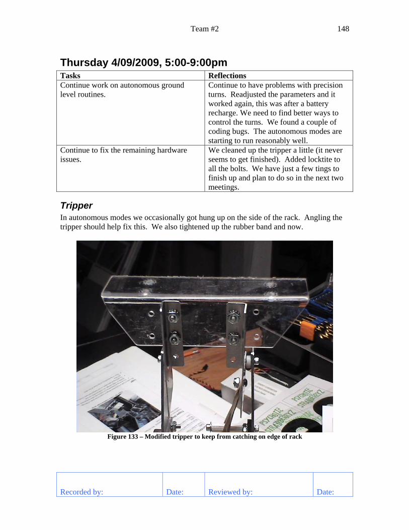
Team #2 148
Recorded by: Date: Reviewed by: Date:
Thursday 4/09/2009, 5:00-9:00pm Tasks Reflections Continue work on autonomous ground level routines.
Continue to have problems with precision turns. Readjusted the parameters and it worked again, this was after a battery recharge. We need to find better ways to control the turns. We found a couple of coding bugs. The autonomous modes are starting to run reasonably well.
Continue to fix the remaining hardware issues.
We cleaned up the tripper a little (it never seems to get finished). Added locktite to all the bolts. We have just a few tings to finish up and plan to do so in the next two meetings.
Tripper In autonomous modes we occasionally got hung up on the side of the rack. Angling the tripper should help fix this. We also tightened up the rubber band and now.
Figure 133 – Modified tripper to keep from catching on edge of rack

Tuesday 4/07/2009, 5:00-9:30pm Team #2 149
Recorded by: Date: Reviewed by: Date:
Autonomous Turning After the scrimmage when we retuned the turning at the other field, we tried the robot on our field. It worked fine. We recharged the batteries and then it required retuning again for it to work. We are currently pulsing the motor for a fixed time at a fixed power. The delay between the NXT and motor control is too long to easily to this interactively. We need to find a way to monitor and control this and react fast enough to handle variations. This will be the main topic for the next meeting.
Key Software Issues The next software tasks that need to be accomplished are:
• Precision turning • Forward until stall. This will minimize the time we need to spend getting the
pucks out of the racks • Properly correct the robot position when the travel angle changes along a path.
Currently, the x, y locations build up errors when we do this. • Have the compass and gyro work together. When we hit something that causes
the robot to lurch, such as the center piece or the rollers, the gyroscope produces a large error and we no longer know where we are pointing. The compass recovers, so we could use it to help reset the gyro.
• Get the autonomous code running to move the robot down the ramp without tipping it over.