2. strain 1 chapter objectives define concept of normal strain define concept of shear strain...
TRANSCRIPT

2. Strain
1
CHAPTER OBJECTIVES
• Define concept of normal strain
• Define concept of shear strain
• Determine normal and shear strain in engineering applications

2. Strain
2
CHAPTER OUTLINE
1. Deformation (not uniform throughout its volume, thus any changes in geometry of any line segment within body may vary along its length)
2. Strain (to describe deformation; changes in length of line segment s & changes in angle btw them).

2. Strain
3
Deformation• Occurs when a force is applied to a body• Can be highly visible or practically unnoticeable• Can also occur when temperature of a body is
changed• Is not uniform throughout a body’s volume, thus
change in geometry of any line segment within body may vary along its length
2.1 DEFORMATION

2. Strain
4
To simplify study of deformation• Assume lines to be very short and located in
neighborhood of a point, and• Take into account the orientation of the line
segment at the point
2.1 DEFORMATION

2. Strain
5
Normal strain• Defined as the elongation or contraction of a line
segment per unit of length• Consider line AB in figure below• After deformation, Δs changes to Δs’
2.2 STRAIN
2. Strain
6
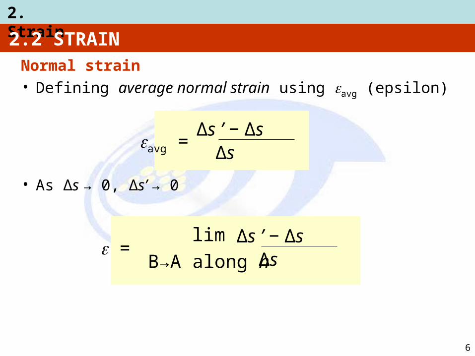
Normal strain• Defining average normal strain using avg (epsilon)
• As Δs → 0, Δs’ → 0
2.2 STRAIN
avg =Δs ’ − Δs
Δs
=Δs ’ − Δs
Δslim
B→A along n
2. Strain
7
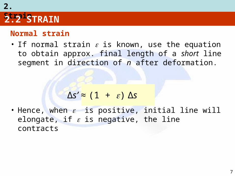
Normal strain• If normal strain is known, use the equation to
obtain approx. final length of a short line segment in direction of n after deformation.
• Hence, when is positive, initial line will elongate, if is negative, the line contracts
2.2 STRAIN
Δs’ ≈ (1 + ) Δs
2. Strain
8
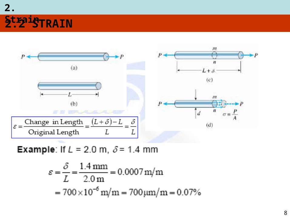
2.2 STRAIN
2. Strain
9
2.2 STRAIN
Units • Normal strain is a dimensionless quantity, as
it’s a ratio of two lengths• But common practice to state it in terms of
meters/meter (m/m) is small for most engineering applications, so
is normally expressed as micrometers per meter (μm/m) where 1 μm = 10−6
• Also expressed as a percentage, e.g., 0.001 m/m = 0.1 %
2. Strain
10
2.2 STRAIN
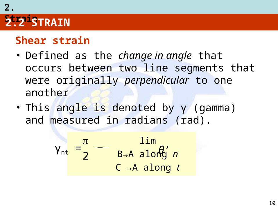
Shear strain• Defined as the change in angle that occurs
between two line segments that were originally perpendicular to one another
• This angle is denoted by γ (gamma) and measured in radians (rad).
γnt =2
lim
B→A along n
C →A along t
θ’−
2. Strain
11
2.2 STRAIN
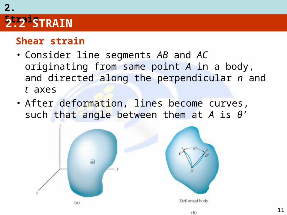
Shear strain• Consider line segments AB and AC originating
from same point A in a body, and directed along the perpendicular n and t axes
• After deformation, lines become curves, such that angle between them at A is θ’
2. Strain
12
2.2 STRAIN

2. Strain
13
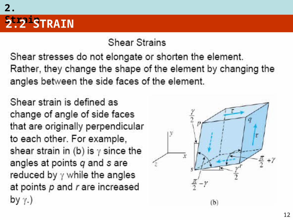
• Normal strains cause a change in its volume of a rectangular element.
• Shear strains cause a change in its shape of a rectangular element.
Small strain analysis• Most engineering design involves applications
for which only small deformations are allowed• We’ll assume that deformations that take place
within a body are almost infinitesimal, so normal strains occurring within material are very small compared to 1, i.e., << 1.

2. Strain
14
Small strain analysis
• This assumption is widely applied in practical engineering problems, and is referred to as small strain analysis
2.2 STRAIN

2. Strain
15
EXAMPLE 2.1
Rod below is subjected to temperature increase along its axis, creating a normal strain of z = 40(10−3)z1/2, where z is given in meters.
Determine (a) displacement of end B of rod due to temperature increase, (b) average normal strain in the rod.

2. Strain
16
EXAMPLE 2.1 (SOLN)
(a) Since normal strain reported at each point along the rod, a differential segment dz, located at position z has a deformed length:
dz’ = [1 + 40(10−3)z1/2] dz

2. Strain
17
EXAMPLE 2.1 (SOLN)
(a) Sum total of these segments along axis yields deformed length of the rod, i.e.,z’ = ∫0 [1 + 40(10−3)z1/2] dz
= z + 40(10−3)(⅔ z3/2)|0= 0.20239 m
0.2 m
0.2 m
Displacement of end of rod is
ΔB = 0.20239 m − 0.2 m = 2.39 mm ↓
2. Strain
18
EXAMPLE 2.1 (SOLN)
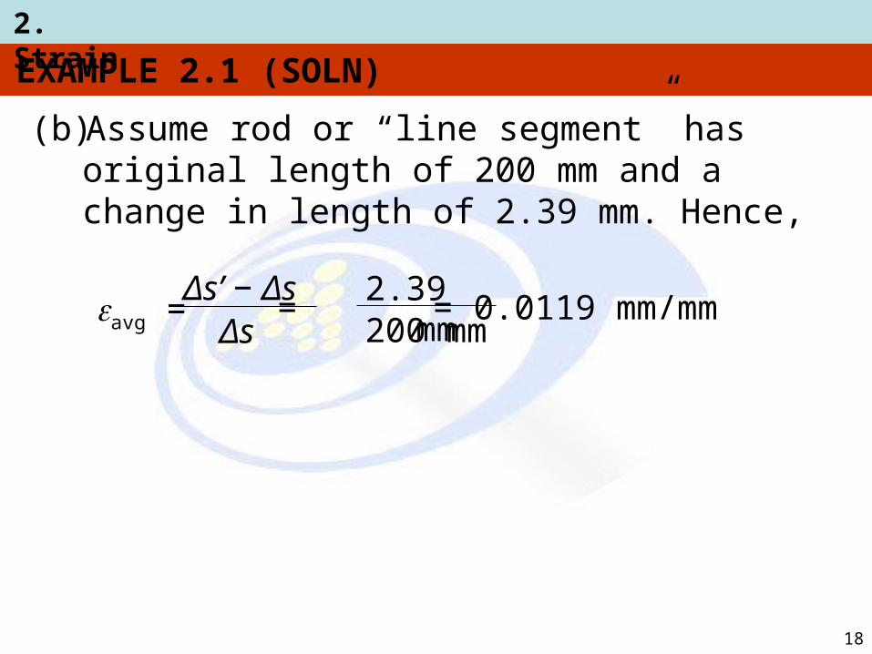
(b) Assume rod or “line segment” has original length of 200 mm and a change in length of 2.39 mm. Hence,
avg = Δs’ − Δs
Δs=
2.39 mm200 mm
= 0.0119 mm/mm
2. Strain
19

2. Strain
20
EXAMPLE 2.3
Plate is deformed as shown in figure. In this deformed shape, horizontal lines on the on plate remain horizontal and do not change their length.Determine
(a) average normal strain along side AB,
(b) average shear strain in the plate relative to x and y axes

2. Strain
21
EXAMPLE 2.3 (SOLN)
(a) Line AB, coincident with y axis, becomes line AB’ after deformation. Length of line AB’ is
AB’ = √ (250 − 2)2 + (3)2 = 248.018 mm

2. Strain
22
EXAMPLE 2.3 (SOLN)
(a) Therefore, average normal strain for AB is,
= −7.93(10−3) mm/mm
(AB)avg = ABAB’ − AB 248.018 mm − 250 mm
250 mm=
Negative sign means strain causes a contraction of AB.

2. Strain
23
EXAMPLE 2.3 (SOLN)
(b) Due to displacement of B to B’, angle BAC referenced from x, y axes changes to θ’.
Since γxy = /2 − θ’, thus
γxy = tan−1 3 mm250 mm − 2 mm
= 0.0121 rad( )

2. Strain
24
CHAPTER REVIEW
• Loads cause bodies to deform, thus points in the body will undergo displacements or changes in position
• Normal strain is a measure of elongation or contraction of small line segment in the body
• Shear strain is a measure of the change in angle that occurs between two small line segments that are originally perpendicular to each other

2. Strain
25
CHAPTER REVIEW
• Most engineering materials undergo small deformations, so normal strain << 1. This assumption of “small strain analysis” allows us to simplify calculations for normal strain, since first-order approximations can be made about their size