2 cellular systems
TRANSCRIPT

9/6/13 2 Cellular Systems
morse.colorado.edu/~tlen5510/text/classwebch2.html 1/19
Chapter 2Cellular Systems
Wireless communications links are especially useful for mobile applications where large areas of coverage are
required. Wireless communications systems are designed to cover such large areas, and to split them into many
smaller cells. That cellular property introduces many difficulties such as how to hand-over (or handoff) from one
cell to another, while maintaining good service quality. Coverage, capacity, interference, and spectrum reuse are
important concerns of cellular systems; this chapter reviews these aspects as well as the technologies, tools, andstandards used to optimize them.
2.1 Cellular Concepts
The many frequency blocks detailed earlier are used for a variety of communications services. Higher frequencies
(say above 6 GHz) are mostly used for point-to-point services such as dedicated private lines. Lower
frequencies are better suited for broader coverage, and are split into geographical cells.
2.1.1 Frequency Reuse
Covering a large geographic area with limited amount of spectrum leads to the reuse of the same frequency in
multiple locations; this leads to co-channel interference considerations, meaning interference from different areas
(or cells) that use the same frequency channel.1 Co-channel interference considerations are usually approached
by considering the following parameters:
St: total number of RF channels available (given the amount of spectrum and channel width dictated by
technology standard),
S0: number of channels per cell, which reflects system capacity at a given location,
K: the reuse factor, is number of cells in a cluster, which is repeated to provide coverage over a large
area.
The three quantities are linked by the straightforward relation:
(2.1)
The reuse factor K is therefore an import parameter for capacity. Of course the lowest reuse factor (K = 1)
maximizes capacity; but this has to be balanced with interference considerations: indeed a higher reuse factor (K
= 3, 4, 7, or even 19) provides more distance between cells using the same channel, which lowers interferences.
2.1.2 Interference Considerations in Reuse
To quantify interference due to reuse we have to consider how a signal propagates from one cell to another. We
will study propagation models later in chapter 3, but we need a few simple notions here. Assume a propagation
model using a power path loss exponent n, that is a model where power decays in 1⁄Rn (R being the distance

9/6/13 2 Cellular Systems
morse.colorado.edu/~tlen5510/text/classwebch2.html 2/19
separating transmit station from receiver). This means that the ratio of received power to transmit power may be
expressed as Pr⁄Pt = A⁄Rn, where A is some constant.
Figure 2.1: Frequency reuse patterns K =3, 4, and 7, on hexagonal cells. Bold contour shows thepattern of cells repeated to provide wide area coverage. Di shows the shortest distance
between cells reusing the same frequency.
With this model, signal to interference ratios are estimated as
(2.2)
where i0 is the number of co-channel cells nearest to the cell (called first tier or tier one); that number increases
with K. And Di is the distance to the tier-one cells reusing the same frequency (as shown in figure 2.1). In the
case of hexagonal cell approximation the expression simplifies to [1]:
(2.3)

9/6/13 2 Cellular Systems
morse.colorado.edu/~tlen5510/text/classwebch2.html 3/19
We’ll see more details on n further, its values vary typically between 2 and 4 with the types of terrain. We’ll
also see that specific wireless technologies require a certain signal to noise and interference ratio (mostly basedon data rates); so equation (2.3) leads to a minimal acceptable K.
The tradeoff between capacity required and interference level required lead to the choice of K. In some
areas however, that value may need to change, and several techniques are used to improve on it.
2.1.3 Capacity and Coverage
Cellular system need to provide both coverage and capacity. There are many techniques for that, some are verycostly, others cheaper , depending on the situations; they include:
Reducing reuse factor K in congested areas.Adjusting parameters: equipment manufacturers offer many features and functionalities which parameters
may be optimized for specific needs.Changing antennas according to needs: diversity, gain, beam width, down-tilt, etc.
Improving RF components: duplexers, combiners, jumpers, cables, connectors. Base stations may beupgraded to better sensitivity or higher transmit power.
Deploying new Technologies such as bi-directional amplifiers and repeaters, tower-top devices filters andamplifiers, smart antennas, in-building solutions (distributed antennas), etc.
Trunking: increase blocking probability to gain capacityCell splitting: microcells, picocells, femtocells.
Sectoring: often 3 to 6 sectorsRange extension: use repeaters or low-noise amplifiers
Careful network optimization is required to determine where these technique may be most effective. Of course,increasingly efficient standards are also very important, which will be detailed in further sections.
2.1.4 Multiple Access
A major requirement of cellular networks is to provide an efficient technique for multiple devices to access the
wireless system. These techniques include:
FDMA:frequency division multiple access, perhaps the most straightforward, in which every user device uses its
own frequency channel. This method was used in the first generation analog systems.TDMA:
time division multiple access, in which a radio channel is divided in time slots, and use devices use theirallocated time slots. In fact TDMA systems are often hybrid FDMA as well as multiple channels are used,
most 2G systems were TDMA.
CDMA:
code division multiple access, in which orthogonal (or pseudo orthogonal) codes are used to differentiateuser devices. CDMA is very spectrum efficient, and was used by 3G standards. There are several
approaches to achieve CDMA, such as frequency hooping (FH-CDMA)or direct spreading (DS-
CDMA).

9/6/13 2 Cellular Systems
morse.colorado.edu/~tlen5510/text/classwebch2.html 4/19
These are the main multiple access techniques, but subtle extensions and combinations can be devised to obtain
more efficient schemes, which we will examine in later chapters (including orthogonal frequency division
multiplexing - OFDMA).
2.2 System Capacity
Wireless communications deal with at least two main concerns: coverage and capacity. We will look at coverageprediction in the next chapters, and start here with a few words on capacity.
2.2.1 Channel Capacity
One fundamental concept of information theory is one of channel capacity, or how much information can betransmitted in a communication channel. In the 1940’s Claude Shannon invented formal characterization of
information theory and derived the well-known Shanon’s capacity theorem (Theorem 17, [11], p.628. That
theorem applies to wireless communications. A great presentation of this equation can be found in [8] p.82; it
presents a concise derivation of the equation, and includes a good introduction to important information theoryconcepts such as information and entropy.
The Shannon capacity equation gives an upper bound for the capacity in a non-faded channel with added
white Gaussian noise:
(2.4)
where C= capacity (bits/s), W=bandwidth (Hz), S⁄N= signal to noise (and interference) ratio.
That capacity equation assumes one transmitter and one receiver, though multiple antennas can be used in
diversity scheme on the receiving side. The formula will be revisited for multi antenna systems in §10.1.3. Theequation singles out two fundamentally important aspects: bandwidth and SNR. Bandwidth reflects how much
spectrum a wireless system uses, and explains why the spectrum considerations seen in §1.2 are so important:
they have a direct impact on system capacity. SNR of course reflects the quality of the propagation channel, and
will be dealt with in numerous ways: modulation, coding, error correction, and important design choices such ascell sizes and reuse patterns.
2.2.2 Cellular Capacity
Practical capacity of many wireless systems are far from the shannon’s limit (although recent standards arecoming incredibly close to it); and measuring the practical capacity requires different considerations, that are
heavily dependent on implementation and standard choices.
All the widely used digital standards (GSM, ANSI-136, cdmaOne) deal in their own way with how todeploy and optimize capacity. For TDMA, the number of time slots and voice coding characteristics give a
capacity limit, and interference considerations are important as modulations link budget set the limit for coverage.
CDMA systems, however, have no such hard limit: tradeoffs are possible between capacity, coverage, and other
considerations linked to performance (such as likelihood of call setup failure, and dropped calls). The possibility
of soft handoff introduces even more parameters. 2

9/6/13 2 Cellular Systems
morse.colorado.edu/~tlen5510/text/classwebch2.html 5/19
Cellular analog capacity:
Fairly straight forward, every voice channel uses a 30 kHz frequency channel, these frequencies may be
reused according to a reuse pattern, the system is FDMA. The overall capacity simply comes from thetotal amount of spectrum, the channel width and the reuse pattern.
TDMA/FDMA capacity:
In digital systems, capacity improvements mainly come from the voice coding and elaborate schemes
(such as frequency hopping) to decrease reuse factor. (The frequency reuse factor hides a lot ofcomplexity and will be examined in further details ([1] ch. 3.2, and 9.7); its value depends greatly on the
signal to interference levels acceptable to a given cellular system).
CDMA capacity:a usual capacity equation for CDMA systems may be fairly easily derived as follows (for the reverse link):
first examine a base station with N mobiles, its noise and interference power spectral density dues to all
mobiles in that same cell is ISC = (N - 1)Sα, where S is the received power density for each mobile, and α
is the voice activity factor. Other cell interferences IOC are estimated by a reuse fraction β of the same cell
interference level, such that IOC = βISC; (usual values of β are around 1⁄2). The total noise and interference
at the base is therefore Nt = ISC(1 + β). Next assume the mobile signal power density received at the base
station is S = REb⁄W. Eliminating ISC, we derive:
(2.5)
where
W is the channel bandwidth (in Hz),R is the user data bit rate (symbol rate in symbol per second),
Eb⁄Nt is the ratio of energy per bit by total noise (usually given in dB Eb⁄Nt ≈ 7dB),
α is the voice activity factor (for the reverse link), typically 0.5,
and β is the interference reuse fraction, typically around 0.5, and represents the ratio of interference
level from the cell in consideration by interferences due to other cells. (The number 1 + β issometimes called reuse factor, and 1⁄(1 + β) reuse efficiency)
This simple equation (2.5) gives us a number of voice channels in a CDMA frequency channel3, the
relation to the former capacity measure is simply m = N⁄W.
We can already see some hints of CDMA optimization and investigate certain possible improvement for a3G system. In particular: improving α can be achieved with dim and burst capabilities, β with interference
mitigation and antenna downtilt considerations, R with vocoder rate, W with wider band CDMA, Eb⁄Nt
with better coding and interference mitigation techniques.
Some aspects however are omitted in this equation and are required to quantify other capacity
improvements mainly those due to power control, and softer/soft handoff algorithms.
Of course other limitations come into play for wireless systems, such as base station (and mobile) sensitivity,
which may be incorporated into similar formulas; and further considerations come into play such as: forward
power limitations, channel element blocking, backhaul capacity, mobility, and handoff.
A final note on capacity: voice capacity is often given in Erlang, and refers to trunking efficiency given a
9/6/13 2 Cellular Systems
morse.colorado.edu/~tlen5510/text/classwebch2.html 6/19
certain blocking probability. ([2] p. 350, or [1] §3.6.)
2.3 Standard Air Interfaces
We first briefly review current mobile digital technologies, how they were initially introduced, and how and they
evolved. 4
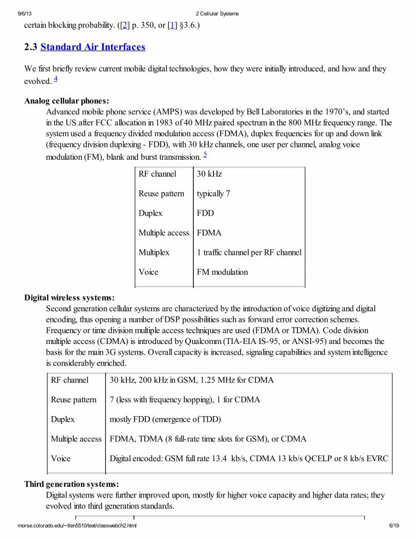
Analog cellular phones:Advanced mobile phone service (AMPS) was developed by Bell Laboratories in the 1970’s, and started
in the US after FCC allocation in 1983 of 40 MHz paired spectrum in the 800 MHz frequency range. The
system used a frequency divided modulation access (FDMA), duplex frequencies for up and down link
(frequency division duplexing - FDD), with 30 kHz channels, one user per channel, analog voice
modulation (FM), blank and burst transmission. 5
RF channel 30 kHz
Reuse pattern typically 7
Duplex FDD
Multiple access FDMA
Multiplex 1 traffic channel per RF channel
Voice FM modulation
Digital wireless systems:
Second generation cellular systems are characterized by the introduction of voice digitizing and digital
encoding, thus opening a number of DSP possibilities such as forward error correction schemes.
Frequency or time division multiple access techniques are used (FDMA or TDMA). Code division
multiple access (CDMA) is introduced by Qualcomm (TIA-EIA IS-95, or ANSI-95) and becomes thebasis for the main 3G systems. Overall capacity is increased, signaling capabilities and system intelligence
is considerably enriched.
RF channel 30 kHz, 200 kHz in GSM, 1.25 MHz for CDMA
Reuse pattern 7 (less with frequency hopping), 1 for CDMA
Duplex mostly FDD (emergence of TDD)
Multiple access FDMA, TDMA (8 full-rate time slots for GSM), or CDMA
Voice Digital encoded: GSM full rate 13.4 kb/s, CDMA 13 kb/s QCELP or 8 kb/s EVRC
Third generation systems:
Digital systems were further improved upon, mostly for higher voice capacity and higher data rates; they
evolved into third generation standards.

9/6/13 2 Cellular Systems
morse.colorado.edu/~tlen5510/text/classwebch2.html 7/19
RF channel 1.25, 5, 10, 15 MHz
Reuse pattern 1 (CDMA)
Duplex mostly FDD, some TDD
Multiple access CDMA
Voice Digital encoded: bit rates 8 kb/s and below
Data Up to several Mbps (3.1 Mbps for EV-DO, 15 Mbps for HSDPA)
Fourth generation systems:
The industry is interested in further improvements towards fourth generation standards (higher throughput,low latency, IP network architecture). Air interfaces of interest focus on multicarrier techniques like
OFDM, and advanced antenna systems such as multiple input multiple output (MIMO) systems.
RF channel generally wider: 10, 20 MHz, more
Reuse pattern 1-1.5 (OFDMA – see §9.3.3)
Duplex FDD or TDD depending on spectrum
Multiple access OFDMA
Voice based onVoIP
Data IP based, flat architecture, convergence
2.4 Speech Coding
The introduction of digital wireless systems means that the acoustic voice wavefront is not simply converted to an
electrical signal directly transmitted over RF channel. Voice is now digitized, encoded, and the resulting bit
stream is transmitted and of course decoded on the receiving side. Although this process requires additional
digital signal processing (DSP), it opens the door to many optimization algorithms and is much more efficient thanusual analog voice transmission.
2.4.1 Basic Vocoder Theory
Digital voice coding (vocoding) is very important yet very subjective. Voice coding theory is a domain of study of
its own; introductory overviews are presented for instance in [2] ch. 15, or [1] ch. 8.
2.4.2 Classic Cellular Vocoders
Analog vocoders have emerged at Bell Laboratories in the late 1920’s, and have become more elaborate and
efficient in dealing with harmonics important to a good understanding of voice (500 Hz to 3400 Hz) while

9/6/13 2 Cellular Systems
morse.colorado.edu/~tlen5510/text/classwebch2.html 8/19
minimizing bandwidth. The digital area brought significant changes. Initial digital systems sampled that range,which at the Nyquist rate leads to a 64 kilobits per second (kbps, kbit/s, or kb/s) bandwidth. This is referred to
as pulse-code modulation (PCM). More elaborate algorithms however can achieve reasonably good voice
transmission by transmitting a codebook (set of parameters for a given voice coding algorithm) with as little as
2.4 kb/s rate: a 26x improvement. Usually these algorithms provide acceptable voice quality, but may provide
poor performance in specific situations such as in a noisy environment, for background music, or when combined
with different voice coding systems (such as PCM) and external voice mail systems. Several vocoder systems
exist and have been chosen in 2G and 3G standards:
CELP:
Code Excited Linear Prediction, 2400 and 4800 bit/s, Federal Standard 1016, used in STU-III.
QCELP:
Qualcomm Code Excited Linear Prediction, developed in 1994, was used in initial IS-95 CDMA
networks. Two bit rates available: QCELP8 and QCELP13 using 8 and 13 kb/s respectively, which is
well adapted for this standard’s 9.6 kb/s and 14.4 kb/s frames. It was later improved upon by EVRC.RCELP:
Relaxed Code Excited Linear Prediction, a more advanced advanced algorithm that does not attempt to
match the original signal exactly but a simplified pitch contour.
EVRC:
Enhanced Variable Rate CODEC is a speech codec used in CDMA networks, it uses RCELP 8 kb/s and
improves quality over 8QCELP. Half rate EVRC were also developed to further lower bitrate at the cost
of some quality.
CVSD:Continuously Variable Slope Delta-modulation, 16 kb/s, used in wide band encryptors such as the KY-
57.
MELP:
Mixed Excitation Linear Prediction, MIL STD 3005, 2.4 kb/s.
ADPCM:
Adaptive Differential Pulse Code Modulation (G.721, G.726).
Comparing the quality differences between vocoder is usually done by testing a number of standard phrases,
and assessing the quality of the transmitted result under various conditions. That assessment is subjective and is
usually given a grade called Mean Opinion Score (MOS) between 0 (completely unintelligible) and 4 (perfect
quality). Initial tests relied on actual opinion surveys, but test devices now offer algorithms providing a MOS and
are regularly used by wireless network operators to benchmark network quality.
2.5 Migration to 3G
Second generation cellular systems certainly achieved major capacity improvements and contributed to the fast
adoption of wireless handsets throughout the world. And the growth continues.
Third generation systems focused on increasing capacity yet again, and on introducing efficient high-speed
mobile data systems. Given past heavy investments in different 2G networks, adoption of a common 3G
standard had tremendous cost implications and competitive advantages.
These efforts from the wireless industry focused on improving widely deployed systems, and migrate them

9/6/13 2 Cellular Systems
morse.colorado.edu/~tlen5510/text/classwebch2.html 9/19
towards a third generation. All major digital technologies proposed an evolution path to a next generation,
typically broader band (in throughput and spectrum).
Several proposals:
Initially 10 new proposals were submitted to the ITU body responsible for standardizing next generation
systems: 2 TDMA, 8 CDMA. (See details in a US contribution to the ITU: US8F01-16, February 2001.)
Harmonization process:
A difficult harmonization effort was undertaken from 1998 to 2001 by the ITU. Many technicalcomparisons and discussions ensued, resulting in some harmonization, but falling short of selecting one
unique worldwide standard.
Successes:
TDMA solutions disappeared. CDMA solutions were narrowed down to two. Other issues such as
spectrum plans and emission levels were also discussed and approved with relative success.
Failures:
One major issue remained: to merge the last two CDMA camps: the 3G partnership project (3GPP)proposed UMTS (WCDMA), and 3GPP2 proposed cdma2000. The former was very reluctant to tread
on intellectual property of the latter, and the latter was adamant about conserving smooth evolution and
backward compatibility with cdmaOne. And discussions stalled; it seemed obvious that neither camp had
any incentive in giving in, hence two competing standards: UMTS-WCDMA and cdma2000.
Figure 2.2: Existing CDMA carrier use (left) is convenient for migration to multicarrier standard,
but may be less efficient than full spreading on same frequency block (right).
In short two major 3G standards remain in competition, and the choice of any carrier is clear: GSM
operators clearly opt for a migration to UMTS (3GPP), and cdmaOne operators to cdma2000 (3GPP2). The
latter is certainly initially cheaper, has advantages in equipment availability, and has well-known performances;but the former may benefit from larger economies of scales as GSM carriers migrate to UMTS services.
In 2002, CDMA Americas Congress (San Diego, December 2002) estimated that cdmaOne operators
benefited from a smooth transition and a well-known standard, thus giving them a one or two year advance over
GSM efforts towards UMTS. Indeed cdma2000 (3G 1X) systems have been available since 2002, IS-856
(3G-1X EV-DO) have been widely available in the US and Asia since 2004. GPRS and UMTS are finally
catching up in 2006. High-speed data services (HSPA) still lag in coverage behind EV-DO in 2008, but mostdense areas in the US are well covered by both technologies.
Choosing a migration path is only the first step; upgrading the network is of course very costly. Initially
service providers had to decide how long to delay network upgrade: voice capacity and time to market for high-
speed data services were the driving factors. Now service providers have to decide how much resources to

9/6/13 2 Cellular Systems
morse.colorado.edu/~tlen5510/text/classwebch2.html 10/19
dedicate to voice versus data.
2.6 Another migration – to 4G
Second generation cellular systems achieved digital voice efficiency, third generation systems focused on
increasing capacity and data rates, what more can a fourth generation standard achieve?
According to most definitions (from the ITU in particular), 4G systems are required to achieve throughputrates around 100Mbps for mobility and 1Gbps for fixed wireless access; so the air interface has to be incredibly
efficient. There are certainly additional requirements (mostly on the network infrastructure) such as low latency,
flat IP architecture, and the use of small cells, heterogeneous networks, and more (which we’ll review in later
chapters).
The main 3G standards have an evolution towards a 4G standard, even if not all aspects are et in its early
iteration, these 4G standards have evolution lines towards true 4G requirements. They have a number ofcommonalities:
LTE:
Long Term Evolution of the current GSM/UMTS/3GPP set of standard is OFDMA on the forward link,
and SC-FDMA (a single carrier OFDMA scheme) on reverse link. Interestingly, GSM carriers migrated
once to CDMA, and now propose to abandon it for OFDMA. LTE promises to carry much of the
international crowd of operators and create economies of scale, allow for international roaming, etc.
WiMAX:WiMAX is a wireless standard based on IEEE 802.16e (and its evolution 802.16m). Its strength is that
(unlike other 4G standards) its evolution path preserves backward compatibility with current 802.16e
systems.
UMB:
For completeness, one should mention here Ultra Mobile Broadband is the proposed evolution for
cdma2000, 3GPP2. But, when the largest major cdma2000 carriers (Verizon Wireless) announced
migration plans towards LTE, all UMB efforts in the industry practically died.
Oddly enough two different camps seem to emerge again: LTE and WiMAX, each backed up by different
suppliers, and different operators, both using very similar technologies (based on OFDMA), and with very few
technical reasons why they should not harmonize to a unique standard.
An important argument to consider is that of spectrum: the vast majority of mobile operators operate in FDD
spectrum (see sections 1.2.3 and 1.3) LTE provided an evolution first in that mode. WiMAX on the other hand
chose to focus first on TDD bands and is the obvious choice for TDD spectrum owners. The overall timeline forevolution is also important: some cellular providers have made significant investments in EV-DO or in HSPA.
Newcomers on the other hand who need high data rates today with smooth evolution towards 4G later may be
more likely to chose WiMAX. Practically however, since 2010 the vast majority of the mobile industry is
following LTE plans, and that standard is becoming the de facto standard for the 4G mobile wireless world.
2.7 Technology Advances
Recent technology advances aim at increasing capacity further. Technology improvements are sometimes the

9/6/13 2 Cellular Systems
morse.colorado.edu/~tlen5510/text/classwebch2.html 11/19
result of a major standard modification, but sometimes simple schemes that can be added to existing standardsand allow for additional improvements with minimal infrastructure changes.
2.7.1 Speech Coding Improvement
Voice coding algorithms and DSP capabilities have improved, and current voice codecs operate on less power,and with greater processing efficiencies. (Refer to [2] ch. 15, or [1] ch. 8 for speech coding details). GSM for
instance is improving voice digitization and quantizing from RPE-LPT to a series of AMR standards. IS-95
systems have a parallel evolution, with EVRC, and half-rate EVRC.
Another standard for selectable mode vocoder (SMV) was in the work but never saw any success in the
industry; it based requirements on: operation in presence of frame erasures, noise suppression recommended for
background noises, reasonable performance with music for on-hold situations, equivalent performances withdifferent languages, multiple quality modes and multiple bit rates, seamless transition from mode to mode. SMV
was design to offer four modes of operations:
Mode 0 is designed to improve voice quality over EVRC with the same capacity requirements as EVRC.
Mode 1 is designed to maintain the quality provided by EVRC while realizing a capacity benefit.
Mode 2 is for the system operator who is willing to sacrifice some voice quality robustness in order to
realize a significant capacity gain.
Similarly, Mode 3 of SMV provides even more capacity gains. But the voice quality is, by toll gradestandards, poor.
The resulting capacity vs. quality tradeoffs seem useful and attractive to service providers, yet this standard never
took off, which may illustrate that some standard evolutions (even when based on sound requirements and good
improvements) may miss their window of opportunity.
2.7.2 Efficient Coding and Modulation
For systems primarily designed for voice, latency was a main concern, and modulations were chosen to be
reliable and operating well at fairly low SNR (like QPSK). For data systems it is advantageous to take
advantage of higher modulation schemes such as 16QAM and 64QAM when the radio link allows it. Highermodulations are more spectral efficient but prone to more bit error rates and may cause more retransmissions,
latency, or jitter.
Data bursts:
when low SNR allows for it, use higher modulation and coding rates for better spectral efficiency.
Adaptive modulation:
fast modulation changes frame by frame allow for efficient scheduling of high speed data bursts when theradio channel is capable of it.
Forward Error Correction:
a very important aspect of wireless communication: error-correcting coding varies from voice to data
bursts; block coding, convolutional coding, and turbo coding can be used optimize efficiency.
ARQ:
automatic retransmit requests are used to lower modulation when necessary and retransmit faded data.

9/6/13 2 Cellular Systems
morse.colorado.edu/~tlen5510/text/classwebch2.html 12/19
2.7.3 Interference Mitigation
Interferences may be cancelled or mitigated by changing antenna patterns as required. Such systems are
sometimes referred to as smart antennas, and are in essence an elaborate extension of sectoring. The aim may be
to balance the load, or steer a main lobe toward a user, or create a null in the direction of an interferer. Some
systems are static, others are dynamic and change with cell load. Some systems are passive others include active
amplification devices. The main types of smart antenna systems may be described as follows:
Active antennas:
An array of passive and active elements using multiple power amplifiers on the transmit side, and a low-noise amplifier on the receive side.
Switched beams:A fixed array of narrow beams, combined to form various size sectors.
Adaptive arrays:
An array of elements offering several degrees of freedom to steer a beam in a certain direction, or createnulls. Array element are sometimes amplified, or attenuated, or are purely passive and utilize phase shift to
create the wanted patterns.Spatial Division Multiple Access (SDMA):
A sophisticated combination of many adaptive elements.
Smart antenna systems are efficient in dense areas. Their cost of equipment however (sometimes due to thecomplex transmit aspect) and large antenna sizes are major drawbacks [9]. Smart antennas are now replaced by
MIMO systems covered in chapter 10.
2.7.4 Diversity
Antenna diversity is a wonderful technique to improve link budgets; receiving diversity simply consists in havingmore than one antenna at the receiving site. Given the power limitations of a mobile handset, receiving diversity
has been implemented at cell site from the early days of cellular systems. Good diversity schemes can add 8 to11dB on the up-link budget, thus significantly improving coverage, quality and capacity on that link. The goal of
antenna diversity is to provide two uncorrelated paths and combine the two signals, thus reducing the probabilityof deep fades. A general guideline is to measure or calculate the correlation coefficient, ρ, and try to achieve the
lowest possible correlation between the two paths.
Diversity improvements are of two kinds: improvements on existing receive diversity in the uplink, andintroduction of transmit diversity for the forward link.

9/6/13 2 Cellular Systems
morse.colorado.edu/~tlen5510/text/classwebch2.html 13/19
Figure 2.3: Test setup to measure several antenna spacing for horizontal space diversity for a PCS
system: antennas are placed 2λ,5λ, and 10λ apart.
Figure 2.4: Cellular networks utilize many types of towers and poles, and even some disguise dependingon the areas to cover. Different antennas make use of different diversity schemes (space for
the left two, polarization for the far right). And some antennas are slightly downtilted (right)to reduce interferences to neighboring cells.
Receive diversity has been used from the early days of cellular, and is as popular as ever. Classic diversity
schemes use two antennas at the base station and some algorithms to combine signals 6
Spatial diversity:Used at every sector, well known combining techniques, probably the most efficient type of diversity.
Angular diversity:

9/6/13 2 Cellular Systems
morse.colorado.edu/~tlen5510/text/classwebch2.html 14/19
Typically of little use, its benefits are usually exploited by softer handoff (within a site) or smart antennas.
Time diversity:Heavily used in modern standards like CDMA: interleaving, half chip offset in I and Q transmission, rakereceivers.
Polarization diversity:Widely used, convenient for small base station sites where antennas cannot be separated.
Transmit diversity is an important feature for forward link capacity improvement. Since handsets are rathersmall, their receive diversity capabilities are limited and there transmit diversity schemes were long ignored, but
are now used in many standards.
Orthogonal Transmit Diversity (OTD):Coded symbol streams are split into two data streams, each containing half the number of symbols,
modulated and spread separately (with two different codes), and transmitted on two different antennasthus doubling transmit rate.
Space-Time Spreading (STS):Coded symbol streams are duplicated into two identical streams, modulated and spread separately (with
two different codes), and transmitted on two different antennas. The key difference with OTD is that inSTS all of the data is sent out on each antenna. This scheme provides redundancy rather than data rateimprovement.
Multiple input, multiple output systems (MIMO):These systems are key to recent wireless standards, from wireless LAN like 802.11n to cellular evolutions
like LTE. MIMO systems use multiple streams encoded differently, transmitted over different antennas,and received by multiple antennas. (See more on MIMO in chapter 10.)
2.7.5 Other Optimization Techniques
Technology advances and standard improvements target an increase in capacity, coverage, data rate, or some
other system performance aspect. In many cases however some simple optimization techniques can be used toincrease performance:
Antenna height: higher for further range, or lower to reduce interference.
Cell splitting (into smaller cells: microcells, picocells, femtocells).Sectoring: often 3 to 6 sectors.
Range extension by repeaters or low-noise amplifiers increase coverage.Antenna downtilt conversely reduce coverage to limit interference with other cells, and are sometimes
necessary as cells are reduced in size for increased capacity. Some antennas use electrical downtilt whileothers are physically tilted down.
And a number of parameter adjustments (power levels, handoff parameters, etc.)
These techniques are very important tools used by operators to optimize capacity and coverage. In some casesoptimization may be seasonal due to foliage or different usage patterns. In all cases RF network demand constant
tweaking to provide optimal performance. More recently self optimizing networks (SON) have the ability tocontinually and automatically optimize these parameters.
2.8 Fixed Wireless Access

9/6/13 2 Cellular Systems
morse.colorado.edu/~tlen5510/text/classwebch2.html 15/19
Fixed wireless access is sometimes referred to as wireless local loop (WLL), and is an alternative to providePlain Old Telephone Services (POTS) and high-speed data services in remote areas where wired solutions are
impractical for various reasons. In most cases, trenching long distances to place communication conduits (forfiber or copper) is very costly, such as in mountainous areas. Cellular service is often scarce too in remote areas.
2.8.1 Classic Architectures
Radio solutions for wireless local loops were rolled-out extensively since the 1970’s. Some such radio services
are still in place, and in use today. Early systems use analog radios to offer voice service over fairly longdistances. Newer WLL system need to be cost-effective, reliable, adaptable to a wide range of situations, andcompliant with local exchange carrier technical, legal, and regulatory standards. But the demand for WLL
services are generally low, and suppliers consequently treat the opportunity as a fairly low priority.
Initially WLL focused on providing extensions of the public switched telephone network (PSTN) to reach
remote customers. As the PSTN evolved to digital voice, digital switching, and Class 5 features (such as callwaiting, caller ID, 3-way calling, and others), WLL systems evolved to include many of these features. WLLproducts therefore focused on providing feature parity for these class 5 services. Connectivity to Class 5
switches like Lucent 5ESS or Nortel DMS100 is specified in Telcordia standards such as GR-303 or GR-008;and WLL systems evolved to use these standard interfaces to the PSTN.
Radio frequencies were allocated for wireless local loop applications, and are referred to as Land MobileRadio (LMR). LMR radio links for telephony use frequencies in the UHF/VHF band (138-512 MHz), which
provide great propagation characteristics even in difficult terrain and heavy tree density. These frequencieshowever are becoming very rare. In fact, they are in such demand that the FCC recently mandated radio systemsto increase their spectral efficiencies, and use only a narrow band of spectrum. Many legacy LMR equipment
using 20-25 kHz RF channels must migrate to narrowband LMR 12.5 kHz channels by January 1, 2013. Inaddition, the FCC order mentions the goal to reach 6.25 kHz channelization so new WLL systems are urged to
deploy these narrow RF channels. 7
Other radio solutions work in the 2.4 GHz and 5 GHz unlicensed bands, building on the popularity and
therefore economies of scale of 802.11a/b/g radios. Unfortunately the popularity of these radios for Wi-Fi LANalso creates a lot of interferences, which is a concern when providing emergency service (911 life line). A few
systems therefore have a 900 MHz version; although less spectrum is available and less power is allowed, thatfrequency can be a very useful alternative. Finally, new TV white spaces are a wonderful new opportunity to
explore.
2.8.2 Cellular WLL
In addition to frequencies mentioned above, wireless carriers can use their licensed spectrum to provide fixedapplications. Fixed radio links usually behave differently from mobile radio links, they are typically less variable intime (therefore easier to predict and equalize), and their fading statistics are generally easier to deal with.
Consequently fixed propagation is usually advantageous for a wireless system. Several important aspects of fixedsystem should be emphasized.
Propagation

9/6/13 2 Cellular Systems
morse.colorado.edu/~tlen5510/text/classwebch2.html 16/19
Mobile communications link are more likely to be obstructed and have a high path loss exponent (see chapter 3;
fixed links on the other hand can use elevated antennas in order to establish near line-of-sight with the basestation and therefore improve propagation characteristics.
Propagation modeling of a fixed radio link has fundamental differences with that of a mobile link. Wireless
propagation models nearly always come from extensive drive testing (hence mobile); collecting fixed data for anempirical model is more difficult: in many cases experimenters present methods to locally average data (over one
half of a wavelength) to remove small-scale fading due to multipath. (Small-scale fading is difficult to quantifyaccurately, and even a large number of fixed data points would provide insufficient sampling to be able to
evaluate its impact.) Another important issue is that of antenna beamwidth (or directivity). Mobile datacollections are conducted using an omnidirectional antenna (isotropic with respect to azimuth). It has long beenknown that the antenna beamwidth and more specifically the distribution of angles of arrival with respect to the
direction of motion of a mobile are important parameters to quantify the fading of a mobile link [1].
Consequently fixed data models may differ in some cases from the usual empirical models. Good fixed
models would be precious for fixed wireless access, but the current use of mobile models is likely to continue fora number of reasons: first, they provide a good estimate for initial design (site-specific models and simulations are
used for more precise predictions); second, some time is necessary to roll-out large fixed wireless systems thatcan be used and analyzed in order to provide a wide modeling range; lastly, the focus of wireless access mostlyremains on mobility.
Advantages of Fixed Links
Fixed links have a few important differences in propagation characteristics, which have a significant impact on
reach, capacity, and therefore overall cost of a fixed wireless system.
Many mobile radio links, especially urban, suffer from fast fading. Fixed links, especially in more ruralareas experience slower fading, mostly due to the changes in the neighboring scatterers. As a result error
rates are typically improved for a given SNR. In an IS-95 CDMA system for instance, the industry usuallyaccepts Eb/No levels of 4 for fixed communication, rather than 7 needed for mobility. All other
parameters being equal, a reduction of Eb/No target of 3dB nearly doubles capacity. (Refer to CDMAcapacity in 2.2.)
Fixed users using narrow antenna beamwidths oriented toward a given base station offers more efficientspectrum reuse patterns than what mobile omnidirectional users require.Fixed usage increases system capacity as it does not require the radio resources that mobile users need to
handover between base stations.Another advantage of narrow beamwidth antennas is that antenna gain is improved. In addition, repeaters
can be strategically placed at customer premise to further improve the link.Antenna heights can be increased to benefit propagation characteristics. Antennas can be placed outdoors
with a cable reaching an indoor device.Another important aspect of the wireless channel is its variability: the mobile channel is typically muchmore variable, a fixed access channel is easier to predict and can therefore be more spectral efficient.
Fixed wireless links can therefore provide increased reach and capacity than equivalent mobile links. As aresult, some of these otherwise costly cellular systems have been used for fixed use, sometimes with minor
modifications. In some cases, wireless local loop base stations became handy to deploy in rural areas to provide

9/6/13 2 Cellular Systems
morse.colorado.edu/~tlen5510/text/classwebch2.html 17/19
extended coverage, and reach minimum service mandated by the FCC for PCS spectrum auctions for instance.
More recently 3G and 4G systems are advertising their fixed capabilities again and may be trying to compete
with other wired broadband services.
2.8.3 Voice Integration
Voice over IP (VoIP) is an efficient and widely accepted method of providing telephony. When consideringwireless transport, the efficient compression of VoIP is an especially valuable property. Most recent WLL radiosolutions therefore use VoIP transport; this is especially convenient as most consumer and enterprise radio
solutions are based on IP and Ethernet. Consequently fairly cheap off-the-shelf systems can be adapted to WLLvoice and data delivery. The problem remains however to interface these systems with the nearest telephony
network. Several architectures are possible for WLL, depending on the location of network elements with voicefeatures.
Figure 2.5: Fixed wireless links, or wireless local loop (WLL) provide fixed wireless voice and/or data
links. Voice services use a voice over IP gateway; additional data services are routed to abroadband data network, and bypass the voice gateway.
In most rural areas, a local central office has TDM voice circuits available rather than a VoIP system, so a
VoIP gateway is required for WLL purposes. Suppliers of WLL systems often have a VoIP gateway as part ofthe solution; until recently, these solutions were still difficult to roll-out because of the VoIP gateway cost, and its
operations integration. Today small size gateways are available at reasonable prices with good interfacestandards. Interfaces from the gateway to the switching fabric have to rely on legacy telephony standards. Onesolution is to connect the VoIP gateway to a telephony CLASS 5 switch via GR-008 or GR-303. These
Telcordia standards allow for a gateway to connect to a switch (with one or two T1 lines), and to access class-5features (such as call waiting, caller ID, 3-way calling, etc.) An alternative solution when GR-008 or GR-303
interfaces are not supported are to simply interface with analog tip and ring lines, but that method has thedisadvantage of offering no remote alarming or troubleshooting capability.
The remainder of the voice transport between the voice gateway and the customer end-point follows typicalIP transport architectures. Network elements usually interface with Ethernet (10/100 sometimes 1000bT). Manyradio systems use a somewhat proprietary physical and MAC layer to insure reliable voice transport, but often
these systems are based on Wi-Fi or WiMAX physical layers. A number of protocols are available to establish areliable IP session that can provide voice transport, including session initiation protocol (SIP), or and Media

9/6/13 2 Cellular Systems
morse.colorado.edu/~tlen5510/text/classwebch2.html 18/19
Gateway Control Protocol (MGCP); ITU recommendation H.323 also provides interoperability standards formultimedia communications over IP including voice features.
2.8.4 Data Services
Data features are also available on many WLL radios, but are somewhat different. Features like fax and low datarates (up to 56kbps) are fairly simple to add to most WLL, but the task is slightly different when trying to add
higher data rates (in the multiple Mbps range). Indeed, higher data rates can no longer interface with the voiceswitch and need to be split into a data network of its own. If a high-speed internet network is available in thearea, data sessions have to be routed to that network while voice traffic needs to be identified as such, and
routed towards the VoIP gateway.
2.9 Homework
1. In a table, list all the wireless technologies popular in modern wireless services (2G, 3G, Wi-Fi, WiMAX,HSPA, LTE). Research and list their main parameters such as: (a) frequency of operation; (b) RF channelbandwidth; (c) peak uplink and downlink data rates; (d) standard body for air interface; (e) modulation
type; (f) multiple access; (g) and some kind of capacity estimate such as throughput per MHz.2. Examine the Shannon capacity equation and comment on what happens in to channel capacity in the
following different situations.a. You operate in a fixed bandwidth W0, and increase the power (S) in the channel. How does
capacity behave?b. You have a limited power radio (therefore S is fixed); you increase system bandwidth, but as you
do that system noise typically increases as well: N = N0W (where N0 is a fixed noise density). How
does capacity behave as bandwidth increases indefinitely? (calculate limit of C as W →∞).
c. You now fix your power spectral density: S = S0W (S0 is your fixed transmit power density). How
does capacity increase with bandwidth?
3. Calculate the capacity (in voice channel per cell per MHz) of the following standards (see §2.2 and 2.3).In each case, simply assume K = 7 as the reuse factor.
a. Verify that AMPS system capacity in independent of the amount of spectrum available, and is m =
4.7 ch./cell/MHz.b. Calculate GSM full rate system capacity. (Answer: m=5.7)
4. CDMA capacity improvement:a. What capacity gain does a CDMA service provider achieve by changing its handset from QCELP
vocoders to EVRC vocoders?b. In addition, the better speech coding allows typical Eb⁄Nt to be reduced from 7 dB to 6.5 dB. What
is the total capacity gain?5. CDMA capacity:
a. Derive in details the capacity formula (2.5) for CDMA systems.
b. Compute a radio system capacity (mCDMA) for IS-95 half rate EVRC (Eb⁄Nt=6.5 dB)
6. Different radio standards system capacity:
a. Compare radio system capacity for above IS-95 half rate EVRC, GSM half rate voice frames,DECT, and PHS (search online, or refer for instance to [1] chapter 11 for the last 2).
b. What are the chances of PHS or DECT to evolve into a 3G standard?7. You invented a new voice coder that allows you to code voice in 4.8 kb/s rather than 9.6 kb/s with no

9/6/13 2 Cellular Systems
morse.colorado.edu/~tlen5510/text/classwebch2.html 19/19
significant voice degradation.a. What will the link budget improvement be?b. Using capacity equations, quantify the impact on network capacity.
8. As an operator, you are faced with the difficult decisions of having to regularly upgrade your network tobetter standards and newer equipment. Assume you are operating a GSM network and you consider
upgrading it to UMTS. Consider (a) price and availability of equipment, (b) timeline to upgrade, (c)impact of other carriers timeline, (d) field experience and proven technology, (e) other considerations.
9. Similarly to the above problem, you now operate a UMTS network with voice and high-speed packetdata. Write a proposal to upgrade it to a fourth generation system using LTE (with the same above
considerations).10. You operate a wireless service in a small town. You installed a CDMA system that can typically support
50 mobile calls per sector, but you chose to offer fixed service only. Refer to section 2.8.2, estimate all
the gain you can realize and assume that they have a direct impact on the system Eb/No. How would youestimate your fixed system capacity.