1n=0.102kgf=0.2248lbs. 12 1mm=0.03937inch accuracy the accuracy of c-lube linear ball spline...
TRANSCRIPT


1 2

43

5 61N=0.102kgf=0.2248lbs.1mm=0.03937inch

7 81N=0.102kgf=0.2248lbs.1mm=0.03937inch

9
Identification Number
101N=0.102kgf=0.2248lbs.1mm=0.03937inch
The specification of C-Lube Linear Ball Spline MAG is indi-
cated by the identification number, consisting of a model code,
a size, a part code, a preload symbol, a classification symbol,
an interchangeable code, and any supplemental codes.
1
2
3
4
5
6
7
8
10
Model code
Size
Part code
Preload symbol
Classification symbol
Interchangeable code
Supplemental code
Series
Lengh of externdl cylinder
Shape of spline shaft
Size
Number of external cylinders
Length of spline shaft
Preload
Accuracy class
Interchangeable specification
Optional specification
9
External cylinder only
Spline shaft only(1)�
Assembled set
Interchangeable specification
Note(1): In case ordering spline shaft only, model code should be changed as LSAG(Solid shaft)or LSAGT(Hollow shaft).
MAG L 5 C1 T1 H S1 /N
LSAG T 5 R150 H S1
MAG L T 5 C1 R150 T1 H S1 /N
MAG L T 5 C1 R150 T1 H /N
Non-interchangeable specification
Assembled set
1 2 3 4 5 6 7 8 9 10 8
C-Lube Linear Ball Spline MAG Standard type :MAG�C-Lube Linear Ball Spline MAG Flange type :MAGF�� For applicable models and sizes, see Table 1.
For the model code of a spline shaft of C-Lube Linear Way
MAG, indicate LSAG(T)regardless the external cylinder model
to be combined.
Series1
Standard :No symbolHigh rigidity long :L2 Length of external cylinder
Solid shaft :No symbolHollow shaft :TShape of spline shaft
4, 5, 6, 8, 10, 124 Size For applicable models and sizes, see Table 1.
3
Table 1 Models and sizes of C-Lube Linear Ball Spline MAGModel
Size
4
5
6
8
10
12
Remark:☆ marks are also applicable to interchangeable specification.
○ ○ ―
☆ ☆ ☆
☆ ☆ ☆
☆ ☆ ☆
☆ ― ☆
☆ ― ☆
Standard model Flanged modelMAG MAGL MAGF
Clearance :T0
Standard :No symbol�Light preload :T1
Specify this item for an assembled set or an interchangeable ex-
ternal cylinder. Applicable preload size and detail of preload
amount, see Table 6 on page 13.
The precision class(P)applies to non-interchangeable specifi-
cation only.
For interchangeable specification products, assemble external
cylinder and a spline shaft of the same accuracy class. For de-
tails of accuracy classes, see page 11 to 12.
Ordinary :No symbol�High class :H�Precision class :P
7
8
Preload
Accuracy class
�
Interchangeable code:S1 S2
Non-interchangeable:No symbol
Specify for interchangeable specification. Interchangeable code
on external cylinder and shaft must be same to match. The per-
formance and the accuracy on set item are same either with S1
or S2. Applicable model and size are shown in Table 1.
“No symbol”shall be indicated for non-interchangeable specifi-
cation.
Interchangeable specification9
/N, /S10 Optional specification For applicable optional specifications, see Table 7 on page 13.
Assembled set :R○�Spline shaft only :R○�
Indicate the length of spline shaft in mm. For standard and
maximum length, see dimension table from page 17.6 Length of spline shaft
Assembled set :C○�External cylinder only:C1
For an assembled set, indicate the number of external cylinder
assembled on one spline shaft. For an interchangeable exter-
nal cylinder only,“C1”is indicated.
5 Number of external cylinder

11 121N=0.102kgf=0.2248lbs.1mm=0.03937inch
AccuracyThe accuracy of C-Lube Linear Ball Spline MAG is
shown in Table 2 and the accuracy of spline shaft is shown
in Table 3 and 4.
Table 2 Accuracy of C-Lube Linear Ball Spline MAG
Table 5 Measuring method of accuracy
A-B
A D B
C
A-B
A-B
Table 4
A-B
A-B
2 3 2
11
Parts mounting part
Support part
Spline partExternal cylinder
(1)�
Parts mounting part
Support part
D C
D C
MAG 4
MAG 5
MAG 6
MAG 8
MAG 10
MAG 12
Note(1):Applicable when measured by using external cylinder for measurement.(2):Applicable when the shaft ends are finished.(3):Applicable to the flange type.(4):Applicable to the non-interchangeable specification.
Remark:The table shows representative model numbers only but is applicable to all other models in the same size.
Note(1):Applicable to non-interchangeable specificationRemark:The values are applicable to any given length of 100 mm
over the effective length of the spline part.
Note(1):Applicable to non-interchangeable specification.Remark:The table shows representative model numbers only but is applicable to all other models in
the same size.
Model number
Relative to axial line of supporting part of spline shaft ③Perpendicularity of mounting surface of flangerelative to axial line of spline shaft(3)①Radial runout of outer periphery of parts mounting part(2)
Ordinary High Precision(4) Ordinary High Precision(4) Ordinary High Precision(4)(No symbol) (H) (P) (No symbol) (H) (P) (No symbol) (H) (P)
②Perpendicularity of spline part end face(2)
33 14 8 22 9 6 27 11 8
33 14 8 22 9 6 27 11 8
33 14 8 22 9 6 27 11 8
33 14 8 22 9 6 27 11 8
41 17 10 22 9 6 33 13 9
41 17 10 22 9 6 33 13 9
Table 4 Total radial runout of axial line of spline shaft unit:μm
Accuracy classOrdinary High Precision(1)
(No symbol) (H) (P)
Allowable value 33 13 6
Overall length of spline shaftmm
― 200 72 46 26 59 36 20
200 315 133 89 57 83 54 32
315 400 185 126 82 103 68 41
400 500 236 163 108 123 82 51
500 630 ― ― ― 151 102 65
630 800 ― ― ― 190 130 85
over incl. Ordinary High Precision(1)Ordinary High Precision(1)(No symbol) (H) (P) (No symbol) (H) (P)
MAG 4MAG 5MAG 6MAG 8
MAG 10MAG 12
Note(1):This accuracy is applicable when special machining is done to the shaft ends.
Measuring item
(1)
Radial runout of periphery ofparts mounting part relative toaxial line of supporting part ofspline shaft.(See Table 2, ①)
While supporting the spline shaft atits supporting parts, place dialgage probes to the outer peripher-al faces of the parts mounting part,and measure the runout from onerotation of the spline shaft.
While supporting the spline shaft atits supporting parts an at onespline shaft end, place a dial gageprobe to the spline end face andmeasure runout from one rotationof the spline shaft.
While supporting the spline shaft atboth center holes and at the out-er peripheral face of the splineshaft adjacent to the external cylin-der, and while fixing the externalcylinder to the spline shaft, placea dial gage probe to the mountingsurface of the flange of the exter-nal cylinder and measure the per-pendicularity from runout causedby one rotation of the spline shaft.
Fix and support the spline shaft.Then apply a unidirectional torsionmoment on the external cylinder(for measurement purpose), beforeplacing a dial gage probe to theside face of the sunk key attachedon the external cylinder. Measurerunout when the external cylinderand the gage probe have traveledtogether 100mm on any effectivepart of the spline shaft. However,the gage probe should be appliedas near as possible to the outerperiphery of the external cylinder.
While supporting the spline shaft atits supporting parts or at both cen-ter holes, place a dial gage probeto the external peripheral face ofthe external cylinder(for measure-ment purpose) , and measurerunout at several positions in theaxial direction while turning thespline shaft one rotation. Use themaximum value.
(1)
Perpendicularity of spline endface relative to axial line ofsupporting part of alpine shaft(See Table 2,②)
Perpendicularity of mountingsurface of flange relative toaxial line of spline shaft(SeeTable 2,③)
Twist of grooves with respectto effective length of thespline part(See Table 3)
Total radial runout of axial lineof spline shaft(See Table 4)
Measuring method Illustration of measuring method
Jigs for fixing
Datum block for traveling of gage probe
Sunk key
100
unit:μm
Table 3 Twist of grooves with respect to effective length of the spline partunit:μm

13 141N=0.102kgf=0.2248lbs.1mm=0.03937inch
Preload
Optional specification
Application Example
Load Rating and LifeThe average amount of preload for C-Lube Linear Ball Spline
MAG is shown in Table 6.
In C-Lube Linear Ball Spline MAG, optional specifications in
Table 7 are available.
When a optional specification is required, add the applicable
supplemental code to the end of the identification number. If
a combination of special specifications(/N and /S)is neces-
sary, arrange supplemental codes in alphabetical order.
(Ex:/NS)
Basic dynamic load rating C
The basic dynamic load rating is defined as a constant load
both in direction and magnitude under which a group of iden-
tical C-Lube Linear Ball Spline MAG is individually operated
and 90% of those in the group can travel 50×103m free from
material damage due to rolling contact fatigue.
Basic static load rating C0
The basic static load rating is defined as a static load that
gives a prescribed constant contact stress at the center of the
contact area between rolling elements and raceways receiving
the maximum load. Generally, the basic static load rating is
used in combination with the static safety factor.
Dynamic rated torque T
The dynamic rated torque is defined as a rotational torque
(See Fig.2)constant both in magnitude and direction under
which 90% of a group of the same C-Lube Linear Ball Spline
MAG can travel 50×103m without suffering from material dam-
age due to rolling contact fatigue when they are individually
operated.
Static rated torque and Static rated moment
T0, TX, TY
The static rated torque and static rated moment are defined
as a static torque or static moment which gives a prescribed
constant contact stress at the center of the contact area be-
tween the steel ball and raceway receiving the maximum load
when a torque or moment(See Fig.2)is loaded. They are
the allowable limit torque or moment that permits normal rolling
motion. Generally, they are used in combination with the sta-
tic safety factor.
Load direction and Load rating
Since the load ratings of C-Lube Linear Ball Spline MAG giv-
en in the dimension table are for upward/downward load, they
must be corrected for the load direction for lateral load. The
corrected basic dynamic load ratings and basic static load rat-
ings are shown in Table 8.
Table 6 PreloadItem
Preload class
Clearance
Standard
Light preload
Note(1):Zero or minimal amount of clearance.(2):Zero or minimal amount of preload.
Remarks:1. Clearance T0 is only available for size 4.Remarks:2. Light preload T1 is not applicable for size 4.Remarks:3. C0 means basic static load rating.
T0 0(1) ・Very smooth motion
(No symbol) 0(2) ・Smooth and precise motion
・Minimum vibrationT1 0.02 C0 ・Load is evenly balanced
・Smooth and precise motion
SymbolPreload amount(N)
Application
Table 7 Special specifications
Special specifications Supplemental code Applicable size
No end seal
Stainless steelspline shaft
Note(1):Applicable to interchangeable external cylinder and assembled set.(2):Applicable to non-interchangeable specification.(3):Not applicable to the hollow shaft.
/N(1) 5~12
/S(2)(3) 5~12
End pressure plateEnd pressure plate
No seal/N
Seals at both ends of external cylinder are replaced by
steel pressure plate. It does not contact to spline shaft
in order to reduce frictional resistance. This is not effec-
tive for dust protection.
Stainless steel spline shaft/S
The material of the solid spline shaft is changed to stain-
less steel. The load rating will be a value obtained by
multiplying the load rating for the high carbon steel spline
shaft by a factor of 0.8.
Upward load
Downward
Lateral load
Fig.1 Load direction
T, T0
TX
TY
Fig.2 Direction of dynamic rated torque, static ratedtorque and static rated moment
Table 8 Conversion factor by load direction
Loaddirection
Size
4~12 C C0 1.47C 1.73C0
Upward and downward load
Basic dynamicload rating
Basic staticload rating
Lateral load
Basic dynamicload rating
Basic staticload rating
Direct Drive Electric Cylinder MAGL

15
Load Rating and Life
161N=0.102kgf=0.2248lbs.1mm=0.03937inch
Precautions for use Precautions for mounting�Fit of external cylinderGenerally, transition fit(J7)is applied between the external
cylinder of C-Lube Linear Ball Spline MAG and the housing
bore. When high accuracy and high rigidity are not required,
clearance fit(H7)may also be applicable.
�Standard mounting example of C-Lube Ball Spline MAGFig.3 shows standard mounting methods of external cylinder.
To prevent the rotation of the external cylinders of MAG4, an
M2 to M2.5 screw are set to the countersink provided on each
cylinder. Avoid deforming the external cylinder when tighten-
ing the screw.
�When mounting multiple sets at the same timeIn interchangeable specification, assemble an external cylinder
and a spline shaft with the same interchangeable code.
In non-interchangeable product, use an assembly of external
cylinder and spline shaft as delivered without changing the
combination.
�Assembling an external cylinder and spline shaftWhen assembling the external cylinder on the spline shaft, cor-
rectly fit the raceway grooves of the external cylinder to that
of the spline shaft and move the external cylinder gently in
parallel direction. Rough handling may cause damaging seals
or dropping steel balls. Non-interchangeable specification prod-
ucts are already assembled so as to provide the best accu-
racy when the marks of external cylinder and spline
shaft face the same direction.(see Fig.4)
�Mounting the external cylinderWhen press-fitting the external cylinder to the housing, as-
semble them correctly by using a press and a suitable jig fix-
ture, etc.(See Fig.5)
MAG 4 MAG MAGFFig.3 Mounting example of external cylinder
JAPAN LSAG 10 H MAG10T1 H
Fig.4 Assembly direction of the external cylinder
Fig.5 Press-fitting of the external cylinder
Table 12 Dimensions and tolerance of attached key
r
r
h
b
C
Model number b Tolerance Toleranceh r C
2.0
2.5
3.0
+0.016+0.006
2
2.5
3
-0.000-0.025
03.8
05.8
07.8
11.8
1.00
1.25
1.50
0.16~0.25
MAG 5
MAG 6
MAG 8
MAG10
MAG12
Remark:The table shows representative model numbers only but is applicable to all other models in the same size.
�Attached keys for the external cylinderThe sunk keys shown in Table 12 are provided with the ex-
ternal cylinder.
unit:mm
Spline Shaft
Lubrication and Dust Protection
LifeThe rating life of C-Lube Linear Ball Spline MAG is obtained
from the following formula.
CL=50(――)3……………………………………………………………………(1)P
TL=50(――)3……………………………………………………………………(2)M
where, L :Rating life, 103m
C:Basic dynamic load rating, N
T :Dynamic rated torque, N・m
P :Theoretically calculated radial load, N
M:Theoretically calculated torque, N・m
If the stroke length and the number of strokes per minute are
given, the life in hours can be obtained from the following for-
mula.
106LLh=―――――― ………………………………………………………………(3)2Sn1×60
where, Lh:Rating life in hours, hours
S :Stroke length, mm
n1:Number of strokes per minute, cpm
Static safety factorWhen excessive large or heavy loads are applied on C-Lube
Linear Ball Spline MAG, local permanent deformation will be
made on balls or raceways, resulting in deterioration in run-
ning performance. In general, the allowable loads depend on
the operating conditions and the requirements in the applica-
tion, and the margin of safety is determined considering the
above factors.
The static safety factor, fs, can be obtained from the follow-
ing formula. General values of this factor are shown in Table
9.
C0fS=―― …………………………………………………………………………(4)P0
T0fS=―― …………………………………………………………………………(5)M0
where, fS :Static safety factor
C0:Basic static load rating, N
P0:Static radial load, N
T0:Static rated torque, N・m
M0:Static torque(maximum torque), N・m
Moment of inertia of sectional area and section modulus of
the spline shaft are shown in Table 11.
Quality lithium-soap base grease containing extreme pressure
additive (ALVANIA EP grease 2 -Shell-) is pre-packed in
C-Lube Linear Ball Spline MAG. Additionally, C-Lube is placed
in the recirculation path, thereby extending the re-lubrication
(greasing) interval time and maintenance for a long period.
C-Lube Linear Ball Spline MAG does not have oil hole and
grease nipple. If re-lubrication is necessary, please put grease
on raceway part of spline shaft.
Product is dust protected by special rubber seals. However, if
large amount of fine contaminants are present, or if large par-
ticles of foreign matter such as dust or chips may fall, it is
recommended to provide protective dust covers such as bel-
lows for the entire linear motion mechanism.
The size 4 model is not provided with seals.
Load factorDue to vibration and/or shocks during machine operation, the
actual load on each rolling guide becomes greater in many
cases than the theoretically calculated load. The applied load
is generally calculated by multiplying the theoretically calculat-
ed load by the load factor shown in Table 10.
Table 9 Static safety factor
Operation with vibration and/or shocks
High operating performance is required.
Normal operation
5 ~ 7
4 ~ 6
3 ~ 5
Table 10 Load factor
Operating conditions fW
Smooth operation free from vibration and/or shock
Normal operation
Operation with vibration and/or shocks
1.0 ~ 1.2
1.2 ~ 1.5
1.5 ~ 3.0
Table 11 Moment of inertia of sectional area and section modulus
Model number
MAG 4
MAG 5
MAG 6
MAG 8
MAG10
MAG12
12 12 6 6
29 29 12 12
61 61 21 21
190 190 49 49
470 460 95 94
990 960 170 160
Moment of inertia of sectional area
mm4
Solid shaft Hollow shaft
Sectional modulus
mm3
Solid shaft Hollow shaft
Remark:The table shows representative model numbers only but is ap-plicable to all models of the same size.
fSOperating conditions
�Additional machining of spline shaftThe high carbon steel spline shaft is hardened by induction
hardening. When additional machining on the shaft end is
needed, make sure that the maximum diameter of the shaft
end machining part does not exceed the dimension d1 shown
in the dimension tables. Spline shafts with special end shapes
can be prepared upon request. Consult for further in-
formation.
�Multiple external cylinders in close contactWhen using multiple external cylinders in close distance to
each other, actual load may be greater than the calculated
load depending on the accuracy of the mounting surfaces and
the reference mounting surfaces of the machine. It is sug-
gested in such cases to assure a greater load than the cal-
culated load. For C-Lube Linear Ball Spline MAG, the key
grooves of the external cylinders are aligned before delivery,
when two or more external cylinders are assembled on a sin-
gle spline shaft and two or more keys are used to fix the ex-
ternal cylinders in the rotational direction.
�Operating temperatureThe maximum operating temperature should not exceed 80℃.
17
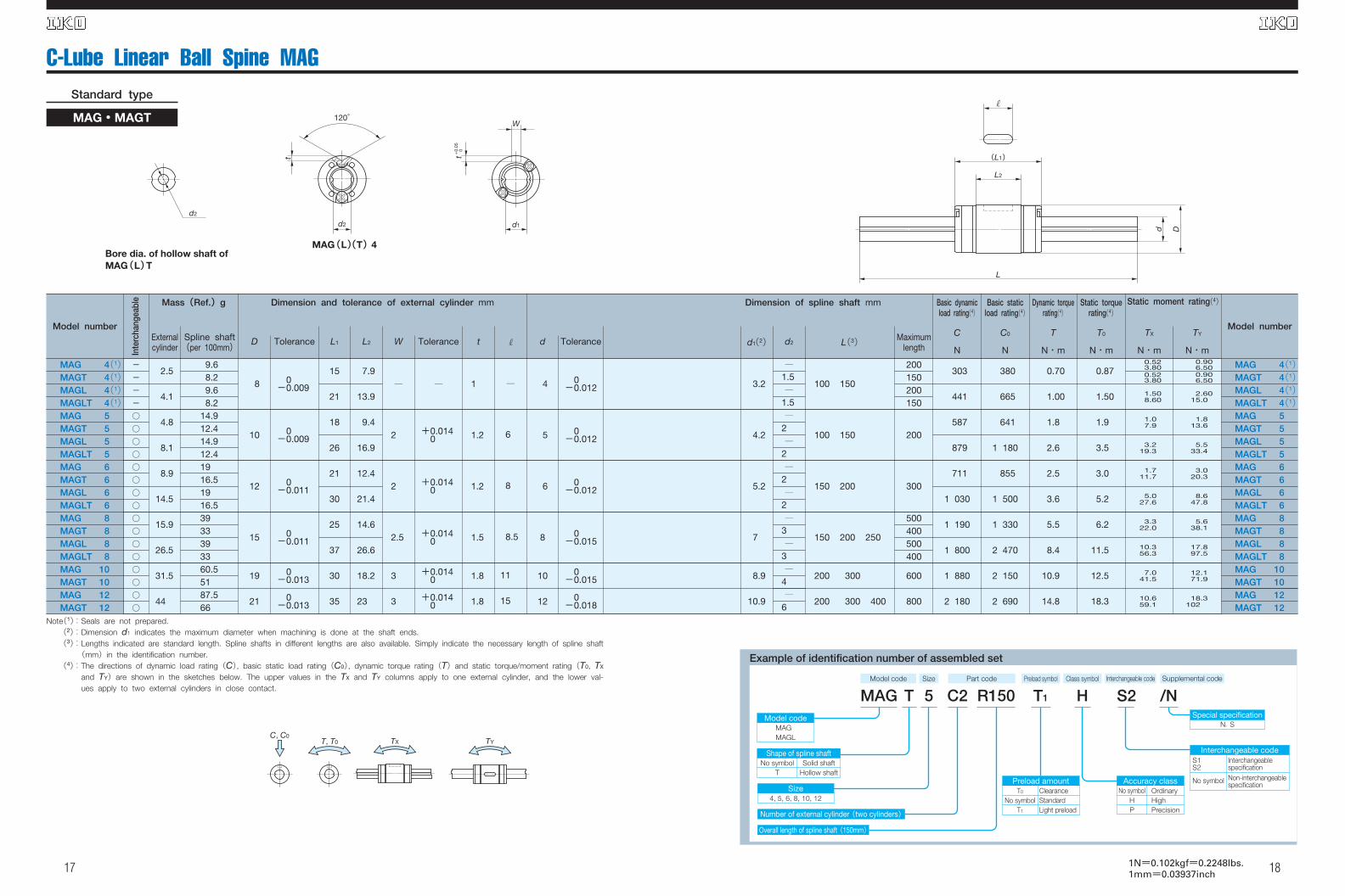
C-Lube Linear Ball Spine MAGStandard type
MAG・MAGT
18
MAG(L)(T) 4Bore dia. of hollow shaft ofMAG(L)T
d2
t
120°�
d1
W
d2
t+0.
05
0
(L1)�
L2
L
d D
Note(1):Seals are not prepared.(2):Dimension d1 indicates the maximum diameter when machining is done at the shaft ends.(3):Lengths indicated are standard length. Spline shafts in different lengths are also available. Simply indicate the necessary length of spline shaft
(mm)in the identification number.(4):The directions of dynamic load rating(C), basic static load rating(C0), dynamic torque rating(T)and static torque/moment rating(T0, TX
and TY)are shown in the sketches below. The upper values in the TX and TY columns apply to one external cylinder, and the lower val-ues apply to two external cylinders in close contact.
TYTXC, C0
T, T0
Example of identification number of assembled set
Size4, 5, 6, 8, 10, 12
Preload amountClearanceStandardLight preload
Accuracy classNo symbol
HP
OrdinaryHighPrecision
Interchangeable codeS1S2
No symbol
Interchangeable specification
T1 S2 /N
T0
No symbolT1
Shape of spline shaftSolid shaft
Hollow shaftNo symbol
T
C2 R1505T HMAGModel code
MAG MAGL
Special specificationN, S
Overall length of spline shaft(150mm)�
Number of external cylinder (two cylinders)�
Non-interchangeable specification
Model code Size Part code Preload symbol Class symbol Supplemental codeInterchangeable code
1N=0.102kgf=0.2248lbs.1mm=0.03937inch
Model number
MAG 4(1)MAGT 4(1)MAGL 4(1)MAGLT 4(1)MAG 5MAGT 5MAGL 5MAGLT 5MAG 6MAGT 6MAGL 6MAGLT 6MAG 8MAGT 8MAGL 8MAGLT 8MAG 10MAGT 10MAG 12MAGT 12
-
-
-
-
○
○
○
○
○
○
○
○
○
○
○
○
○
○
○
○
2.5
4.1
4.8
8.1
8.9
14.5
15.9
26.5
31.5
44
9.68.29.68.2
14.912.414.912.41916.51916.53933393360.55187.566
8
10
12
15
19
21
0-0.009
0-0.009
0-0.011
0-0.011
0-0.013
0-0.013
15
21
18
26
21
30
25
37
30
35
7.9
13.9
9.4
16.9
12.4
21.4
14.6
26.6
18.2
23
3.2
4.2
5.2
7
8.9
10.9
―
1.5―
1.5―
2―
2―
2―
2―
3―
3―
4―
6
100 150
100 150
150 200
150 200 250
200 300
200 300 400
200150200150
200
300
500400500400
600
800
303
441
587
879
711
1 030
1 190
1 800
1 880
2 180
380
665
641
1 180
855
1 500
1 330
2 470
2 150
2 690
0.70
1.00
1.8
2.6
2.5
3.6
5.5
8.4
10.9
14.8
0.87
1.50
1.9
3.5
3.0
5.2
6.2
11.5
12.5
18.3
0.523.800.523.80
1.508.60
1.07.9
3.219.3
1.711.7
5.027.6
3.322.0
10.356.3
7.041.5
10.659.1
0.906.500.906.50
2.6015.0
1.813.6
5.533.4
3.020.3
8.647.8
5.638.1
17.897.5
12.171.9
18.3102
MAG 4(1)MAGT 4(1)MAGL 4(1)MAGLT 4(1)MAG 5MAGT 5MAGL 5MAGLT 5MAG 6MAGT 6MAGL 6MAGLT 6MAG 8MAGT 8MAGL 8MAGLT 8MAG 10MAGT 10MAG 12MAGT 12
―
2
2
2.5
3
3
―
+0.0140
+0.0140
+0.0140
+0.0140
+0.0140
1
1.2
1.2
1.5
1.8
1.8
―
6
8
8.5
11
15
4
5
6
8
10
12
0-0.012
0-0.012
0-0.012
0-0.015
0-0.015
0-0.018
Model number
Inte
rcha
ngea
ble Mass(Ref.)g Dimension and tolerance of external cylinder mm Basic dynamic
load rating(4)Dimension of spline shaft mm Basic static
load rating(4)Dynamic torque
rating(4)Static torque
rating(4)Static moment rating(4)
Externalcylinder
Spline shaft(per 100mm)
D Tolerance L1 L2 W Tolerance t d Tolerance d1(2) d2 L(3) Maximumlength
C
N
C0
N
T
N・m
T0
N・m
TX
N・m
TY
N・m

19
C-Lube Linear Ball Spine MAG
20
Bore dia. of hollow shaft of MAGT
d2
B
d1
4-d3
pcdD1
d D
L
(L1)�
L2
T
(E)�
MAG・MAGT
Flange type
MAGF・MAGFT
C, C0T, T0 TX TY
Example of identification number of assembled set
Size5, 6, 8, 10, 12
Preload amount Accuracy class
Interchangeable code
Overall length of spline shaft(150mm)�
Number of external cylinder (two cylinders)�
T1 S2 /NC2 R1505 HMAGFModel code
MAGF
Special specificationN, S
Shape of spline shaft
T
StandardLight preload
No symbolHP
OrdinaryHighPrecision
S1S2
No symbol
InterchangeablespecificationNon-interchangeablespecification
No symbolT1
Solid shaftHollow shaft
No symbolT
Model code Size Part code Preload symbol Class symbol Supplemental codeInterchangeable code
1N=0.102kgf=0.2248lbs.1mm=0.03937inch
Note(1):Dimension d1 indicates the maximum diameter when machining is done at the shaft ends.(2):Lengths indicated are standard length. Spline shafts in different lengths are also available. Simply indicate the necessary length of spline shaft
(mm)in the identification number.(3):The directions of dynamic load rating(C), basic static load rating(C0), dynamic torque rating(T)and static torque/moment rating(T0, TX
and TY)are shown in the sketches below. The upper values in the TX and TY columns apply to one external cylinder, and the lower val-ues apply to two external cylinders in close contact.
Model number
MAGF 5
MAGFT 5
MAGF 6
MAGFT 6
MAGF 8
MAGFT 8
MAGF 10
MAGFT 10
MAGF 12
MAGFT 12
○
○
○
○
○
○
○
○
○
○
8.9
13.9
23.5
45
59
14.9
12.4
19
16.5
39
33
60.5
51
87.5
66
10
12
15
19
21
0
-0.009
0
-0.011
0
-0.011
0
-0.013
0
-0.013
18
21
25
30
35
9.4
12.4
14.6
18.2
23
23
25
28
36
38
4.2
5.2
7
8.9
10.9
―
2
―
2
―
3
―
4
―
6
100 150
150 200
150 200 250
200 300
200 300 400
200
300
500
400
600
800
587
711
1 190
1 880
2 180
641
855
1 330
2 150
2 690
1.8
2.5
5.5
10.9
14.8
1.9
3.0
6.2
12.5
18.3
1.0
7.9
1.7
11.7
3.3
22.0
7.0
41.5
10.6
59.1
1.8
13.6
3.0
20.3
5.6
38.1
12.1
71.9
18.3
102
MAGF 5
MAGFT 5
MAGF 6
MAGFT 6
MAGF 8
MAGFT 8
MAGF 10
MAGFT 10
MAGF 12
MAGFT 12
18
20
22
28
30
7
7
9
10
10
2.7
2.7
3.8
4.1
4
17
19
22
28
30
3.4
3.4
3.4
4.5
4.5
5
6
8
10
12
0
-0.012
0
-0.012
0
-0.015
0
-0.015
0
-0.018
Model number
Inte
rcha
ngea
ble Mass(Ref.)g Dimension and tolerance of external cylinder mm Basic dynamic
load rating(3)Dimension of spline shaft mm Basic static
load rating(3)Dynamic torque
rating(3)Static torque
rating(3)Static moment rating(3)
Externalcylinder
Spline shaft(per 100mm)
D Tolerance L1 L2 D1 B E T PCD d3 d Tolerance d1(1) d2 L(2)Maximum
length
C
N
C0
N
T
N・m
T0
N・m
TX
N・m
TY
N・m

21 22