1.mastering math - high school math review
TRANSCRIPT
1. Mastering Math - High School Math Review
This math review is intended to prepare students for the first-year math used in the core
engineering courses. This material is accompanied by a corresponding review video posted
on the First Year Engineering YouTube channel. This worksheet will cover a review of 3-D
vectors, an engineering application, and a practice problem set. This review was developed by
John O’Keefe along with the Elsie MacGill Learning Centre.
1.1 3-D Vectors
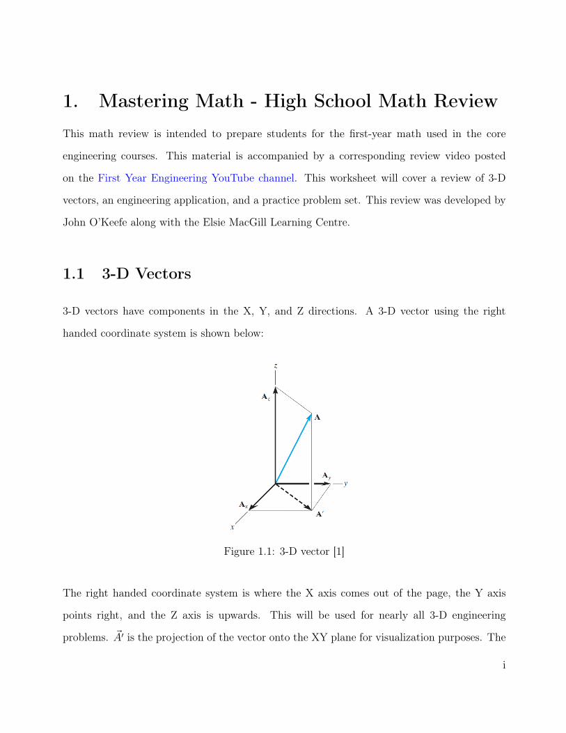
3-D vectors have components in the X, Y, and Z directions. A 3-D vector using the right
handed coordinate system is shown below:
Figure 1.1: 3-D vector [1]
The right handed coordinate system is where the X axis comes out of the page, the Y axis
points right, and the Z axis is upwards. This will be used for nearly all 3-D engineering
problems. ~A′ is the projection of the vector onto the XY plane for visualization purposes. The
i
vector ~A has components in all three directions as shown below:
~A = Axi+ Ay j + Azk (1.1)
Where i is a unit vector in the X direction, j is a unit vector in the Y direction, and k is a unit
vector in the Z direction of the vector, ~V . Unit vectors have a magnitude of 1 but provide the
direction of the component.
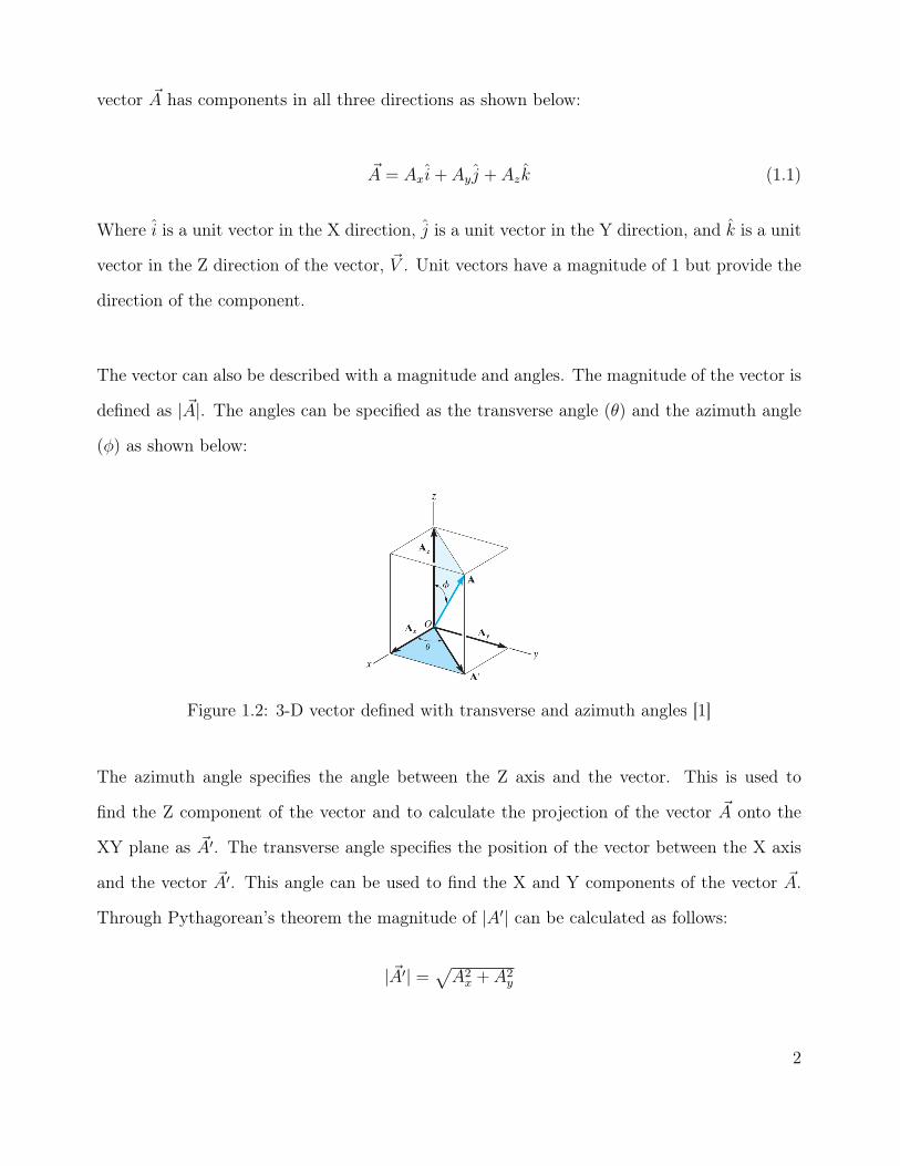
The vector can also be described with a magnitude and angles. The magnitude of the vector is
defined as | ~A|. The angles can be specified as the transverse angle (θ) and the azimuth angle
(φ) as shown below:
Figure 1.2: 3-D vector defined with transverse and azimuth angles [1]
The azimuth angle specifies the angle between the Z axis and the vector. This is used to
find the Z component of the vector and to calculate the projection of the vector ~A onto the
XY plane as ~A′. The transverse angle specifies the position of the vector between the X axis
and the vector ~A′. This angle can be used to find the X and Y components of the vector ~A.
Through Pythagorean’s theorem the magnitude of |A′| can be calculated as follows:
| ~A′| =√A2
x + A2y
2

Similarly this can be applied to the azimuth triangle to find an expression for the magnitude
of | ~A|:
| ~A| =√| ~A′|2 + A2
z
Substituting | ~A′| into the second expression leads to an expression for the magnitude of the
vector |A| as a function of the components.
| ~A| =√A2
x + A2y + A2
z (1.2)
The angles can be calculated according to trigonometry as follows:
φ = tan−1
(√A2
x + A2y
Az
)(1.3)
θ = tan−1(Ay
Ax
)(1.4)
Given the magnitude, transverse angle, and azimuth angle the components can be calculated
as follows:
~A′ = | ~A| sin(φ) (1.5)
Ax = ~A′ cos(θ) = | ~A| sin(φ) cos(θ) (1.6)
Ay = ~A′ sin(θ) = | ~A| sin(φ) sin(θ) (1.7)
Az = | ~A| cos(φ) (1.8)
3

Memorizing these equations isn’t useful as the angles provided consistently change between
problems. Understanding the process on how these equations are derived is more important.
Vectors can also be described by using two points as shown between A and B.
Figure 1.3: 3-D vector between two points [1]
By subtracting point B from point A the position vector from A to B is obtained. In component
form the vector ~r can be described by:
~r = (xB − xA)i+ (yB − yA)j + (zB − zA)k = ∆xBAi+ ∆yBAj + ∆zBAk (1.9)
1.1.1 Examples
1. Determine the components of a 3-D vector with a magnitude of 6 kN, a transverse angle of
θ = 10◦, and an azimuth angle of φ = 30◦.
4

Figure 1.4: Example 1
Solution: The question stated the transverse angle and azimuth angle were provided, therefore
equations 1.6, 1.7, and 1.8 are applicable.
Vx = 6 sin(30) cos(10)
Vx = 2.95
Vy = 6 sin(30) sin(10)
Vy = 0.52
Vz = 6 cos(30)
Vz = 5.20
2. Determine the magnitude and direction of the following 3-D vector:
Figure 1.5: Example 2 [3]
5
Solution: The magnitude can be determined according to Eq. 1.2
|~P | =√
22 + 32 + 52
|~P | = 6.16
The transverse and azimuth angles can be calculated according to Eq. 1.4 and Eq. 1.3.
θ = tan−1(
3
2
)θ = 56◦
φ = tan−1(
5√22 + 32
)φ = 53◦
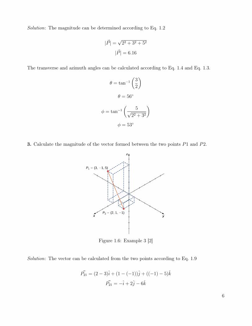
3. Calculate the magnitude of the vector formed between the two points P1 and P2.
Figure 1.6: Example 3 [2]
Solution: The vector can be calculated from the two points according to Eq. 1.9
~P21 = (2− 3)i+ (1− (−1))j + ((−1)− 5)k
~P21 = −i+ 2j − 6k
6

The magnitude can be determined according to Eq. 1.2
| ~P21| =√
(−1)2 + 22 + (−6)2
| ~P21| = 6.40
1.1.2 Engineering Examples
3-D vectors are mostly used in Statics (ECOR 1045) to solve for forces or position vectors.
The majority of Dynamics problems are in 2-D.
1. Calculate the components of the force, ~F .
Figure 1.7: Engineering example 1 [1]
Solution: Two angles are provided for this vector, but the angle (φ) is provided from the
XY plane rather than the Z axis. The magnitude of the force ~F is provided as 750 N. The
components can be calculated as follows:
Fx = 750 cos(45) cos(60)
Fx = 265 N
The Y component of the force is in the negative direction:
7

Fy = −750 cos(45) sin(60)
Fy = −459 N
Fz = 750 sin(45)
Fz = 530 N
2. Calculate the components of the force, ~F1.
Figure 1.8: Engineering example 2 [1]
Solution: This question provides a ratio for the azimuth angle and provides the transverse
angle. The magnitude of the force is provided as 125 N . The components can be calculated
as follows:
Fx = 125(4/5) cos(20)
Fx = 94.0 N
The Y component of the force is in the negative direction.
Fy = −125(4/5) sin(20)
Fy = −34.2 N
Fz = 125(3/5)
Fz = 75 N
8

3. Calculate the vector connecting A to B.
Figure 1.9: Engineering example 3 [1]
Solution: To determine the vector between two points Eq. 1.9 can be applied:
A = (2, 0, 4)
B = (−2, 7, 0)
~r = (−2− 2)i+ (7− 0)j + (0− 4)k
~r = −4i+ 7j − 4k
This is the component form of the vector ~r. This is sufficient since the question does not ask
for the magnitude.
1.1.3 Practice Problems
1. Determine the components of a 3-D vector with a magnitude of 20 kN at a transverse angle
of θ = 30◦ and an azimuth angle of φ = 45◦.
2. Determine the components of the 3-D vector shown below.
9

Figure 1.10: Problem 2 [1]
3. Determine the components of the 3-D vector shown below.
Figure 1.11: Problem 3 [1]
4. Determine the components of the 3-D vector shown below.
Figure 1.12: Problem 4 [1]
10

5. Determine the vectors of ~BA and ~CA below.
Figure 1.13: Problem 5 [1]
6. Determine the vector ~BA below.
Figure 1.14: Problem 6 [1]
11

1.1.4 Answers
1. 12.2i+ 7.1j + 14.1k
2. 35.4i− 35.4j + 86.6k
3. 145i+ 399j + 424k
4. 346i− 200j + 693k
5. −2i+ 4j − 4k, −6i+ 3j − 2k
6. 2i+ 3j − 6k
12
Bibliography
[1] R C Hibbeler. Engineering Mechanics Statics 14th Edition. Pearson, 2016.
[2] LibreTexts. Vectors in three dimensions. https://math.libretexts.org, Jan 2020. Ac-
cessed on 2020-06-12.
[3] Interactive Mathematics. Vectors in 3d space. https://www.intmath.com, Jun 2019.
Accessed on 2020-06-12.
13