1988 brewe khonsari new current cavitation
DESCRIPTION
1988 Brewe Khonsari Current CavitationTRANSCRIPT

BII FLECON~
NASA AV$COM,Technical- Memorandum 103184 Technical Memorandum -89,-C-007
SCurrent Research inNCavitating Fluid Films
Edited by
-- D.E. Brewe,Propulsioh Directorate,U.S., ArmnyAviation Systenis CommandLewis Researc Center'Ckiveland, Ohio
J.H. Ball D7 1,*Waukesha Bearingsv'C'orp. - IEI
Waukesha, Wiscor~i. -t
-and'-
M.M. Khotisar~i*lliversity(f1 , Pittsburgh
-pittsburgii, Pennsylvania
'Prpared for theCavitation, Symposium-11988 Society of Tribologists and,Lubrication Engineers. Aninual-MetingCle\'9land,, Ohij, May9,,18
Apprcv :d t~i: usfl zee~U RMY,AVIATION '-SYSTEMSC,6bWAND.'AVIATION R&T ACTIVITY
90 12 10

CURRENT RESEARCH IN CAVITATING FLUID FILMS
Edited by
D.E. BREWE, STLE Member J.H. BALL, STLE MemberU.S. Army Propulsion Directorate Waukesha'Bearings Corporation
NASA Lewis Research Center Waukesha, Wisconsin 53187Cleveland, Ohio 44135
M.M. KHONSARI, STLE MemberDept. of Mechanical Engineering
University of Pittsbu-ghPittsburgh, Pennsylvania 15261
ABST_ACT This article is divided into three parts. Inthe first part, we present experimental results to
The 1988 STLE Annual Meeting held a two- provide the reader with the observed phenomena assession symposium on cavitation in fluid films. well as some of the pertinent measurements; theThis paper is an edited review of the current second part of the paper deals with theoreticalresearch as discussed by the invited participants, modeling techniques. Part III consists of thePhenomena and experimental observations included editor's summary.gaseous cavitation, vapor cavitation, and gasentrainment. Cavitation in flooded, starved, and In the text that follows, different types ofdynamically loaded journal bearincjs, as well as cavitation are described:squeeze-film dampers was reviewed. Observationsof cavitation damage in bearings and the possi- Gaseous Cavitationbility of cavitation between parallel plates withmicroasperities were discussed. The session on The lubricating oil often contains some dis-theoretical modeling summarized the transcavity solved air and/or other gases. It is, therefore,fluid transport process, meniscus motion, and likely that these gases could come out of thegeometry, or form, of the film during rupture and solution if the fluid pressure falls below thereformation. Performance effects were related to saturation prcssure of the dissolved gases (nearlyheat-transfer models in the cavitated region and atmospheric pressure). This type of cavitationhysteresis influences on rotor-dynamic coeffi- is called gaseous cavitation. In journal bearingscdents. Contributors presented a number of under steady-state conditions, one would generallycavitatiih algorithms together with solution expect gaseous cavitation to take place in theprocedures' sing the finite-difference and finite- divergent region where the mating surfaces tend toelement meth'oi s. Although Newtonian fluids were pull the lubricant apart, thus creating the condi-assumed in mo t of the discussions, the effect of tion in which the gases could emerge from thenon-Newtonian fluIds on cavitation was also solution and give rise to "atmospheric pressure".discussed. Side entrainment is another manifestation of
gaseous cavitation when bubbles at the ambientINTRODUCTION pressure of the sides are drawn into the nrgat!Ve
This paper is a survey of the state-of-the- pressure regions of the bearing.
art in research in cavitating fluid-film bearings Vapor Cavitationand seals based on a symposium held at the STLEAnnual Conference in Cleveland, Ohio, in May if the local pressure of thp fluid coincides1988. The purpose of this article is to discuss with that of the vapor pressure, then the boilingthe fundamental issues, experimental observations, of the fluid by pressure reduction causes thetheoretical modeling techniques, and further formation of a so-called vapor cavitation. Thisresearch needed in this field. It Is hoped that type of cavitation normally occurs in dynamicallythis paper can serve as a reference publication loaded bearings used in common machinery.for both the experienced researcher and those whoare becoming Interested in this area. Neverthe- Understanding the mechanism of the formationless, this article is not a general review paper, and collapse of cavitation bubbles is of funda-as it is largely based on the viewooints of the mental importance since it is known to affect theparticipants in the symposium. Each participant performance of the bearing. Furthermore, it isprovided a short position paper covering his the vapor cavitation that is known to be harmfulpresentation from which the editors have drawn as the bubbles violently collapse against thefreely. bushing surfaces, resulting in cavitation damage.

CONTENTS
Page
PART I -- FUNDAMENTAL AND EXPERIMENTAL OBSERVATION .......... I
Nomenclature to Part I . . . . . . . . . . . . . . . . . . . . . 3
Experimental Studies in Cavitation ...... ................. 4H. Heshmat
Cavitation in Journal Bearings and Squeeze Film Dampers:Experimental ..... .. .. ........................... 9B. Jacobson
Categorization of Cavitation Types and Onset Conditions ... ....... 11D.N. Parkins
Cavitation in Microsperity Lubrication ..... ............... isA.O. Lebeck
Cavitation Erosion Damage in Engine Bearings .... ............ 17F.A. Martin
Refei'ences to Part I ..... ... ....................... 21
PART II -- THEORETICAL MODELING AND PERFORMANCE .... ............ 23
Introduction ..... .. .. ............................ 25
Nomenclature to Part II ....... ....................... 27
Development and Evaluation of a Cavitation Algorithm ... ........ 29T.G. Keith and D. Vijayaraghavan
Fundamental Issues Concerning the Moving Boundary .... .......... 34L da H.T. Pan and Jean Frene
Geometry and Motion of the Meniscus ..... ................. 37Jean Frene, Luc Launay, and Coda H.T. Pan
Classic Cavitation Models for Finite Element Analysis ... ........ 39J.F. Booker
Mathematical Models and Related Algorithms in Cavitation Problems . . 41C. Bayada, N. Chambat, M. El Alaoui
Non-Newtonian Effects in Film Cavitation ..... .............. c 43A.Z. Szeri, K.R. Rajagopal, and Zhang AccesionFor
Cavitation Modeling for Analysis of Fluid Film Journal Bearings . . 47 NTIS CRA&IL.E. Barrett and L.A. Branagan DTIC TAB El
U,.a~iiounced 0]A Model for Cavitation In Dynamic Systems ..... .............. 49 Justification
John A. Tichy and C.P. Ku ...................
The Influence of Cavitation on Journal-Bearing ByRotordynamic Characteristics ...... ................... 52 Di.. ibtio:.M.L. Adams
Cavitation in Journal Bearings and Squeeze-Film Dampers: Availabilily Co.cesAnalytical . ... .. .. .. .. .. .......................... .. 54 Dva;, cil°B. Jacobson Aa#&Ao
Dist SpcaReferences to Part II ...... .. ........................ 57
PAI I
iil

PART I
FUNDAMENTAL AND EXPERIMENTAL OBSERVATION

NOMENCLATURE Yo Initial film thickness, m
b Pad width, m z Coordinate in axial direction, m
C Bearing radial clearance, m a Fluid film arc, rad
D Bearing diameter, m C Eccentricity ratio of bearing (e/c)
d Depth of oil, m e Coordinate in plane of rotation, rad
e Eccentricity, m eo Angle of line of centers, rad
F Force, N 11 Viscosity, Ns/m 2
f Frequency of load (Hz), s-l pt Coefficient of friction
G Duty parameter, [pUb/Wl a Shear stress, N/m2
h Film thickriess, m t Period of dynamic load, s
ha Amplitude of oscillation, m @ Atti,:ude angle, ( 0 - Tr), rad
L Length of bearing in z-direction, m W Angular velocity of shaft, rad/s
N Shaft rotational frequency, rev/min Subscripts:
P Unit loading (W/LD) 8 Beginning of bearing pad
Ps Oil supply pressure, m3/s d Dynamic
Q Volumetric oil flow, m3/s E End of bearing pad
QI(O.5 UCL) F Full fluid film
R Bearing or journal radius, m min Minimum
t Time, s S Starvation
U Linear velocity, m/s s Static, supply
u Velocity of the fluid in the circumfer- st Steadyential direction, m/s
I Start of fluid filmN Load on bearing, N
2 End of fluid filmx Coordinate in circumferential direction,
m
y Coordinate in radial or normal direction, m
3

EXPERIMENTAL STUDIES IN CAVITATION
H. HESHMAT I
The experiments cited here deal primarily Extentofwith the flow and formation of oil streamlets in Pressure Profilecavitated regions. Extent of
eearing Pad 0
FLOODED BEARINGS
Consider Fig. 1, which deptcts a hydro- 0 1W6
dynamic journal bearing. As shown, the fluid oil A
film ends at e2 after which it cavitates; Groove7 N ...- View 6the space at 0 6)92 is filled with oil stream- .lets, released gasses, ambient air, and possibly A '. "
oil vapor. In the absence of hydrodynamic posi- .- . . r h -n
tive pressures in the region e2 - 6E , the amount .0of flow (62) leaving Q2 remains constant at '->/" ...all 6 > e2. If one observes the cavitationregion through the bearing t ansparent shell, onesees fluid film streamlets in the manner shown in (0/2) Cavitaton Zoneview B of Fig. 1. A sample of such experimen- /tally observed streamlets seen through a transpa- Z=orent bearing shell is shown in Fig. 2 (cf. (1)). View A-A L....-This figure reveals that the oil adhering to the ; '02stationary surface is in narrow strips. The t ,
fluid film emerging from a cavitated region 81 z(0,/2) 2 0E
beyond the physical end of the pad 6E is shownin Fig. 3. The pattern of ridges and troughs in-dicates that next to the shaft is a sublayer offluid that completely covers the rotating shaft.This is unlike the stationary surface. The fluid Lucoam. etc.as it emerges from the bearing pad does not leave....the shaft but adheres to it even when the film is -not restrained by an upper bearing surface but is View B .-'.. . ..-
open to the atmosphere. The streamlets thus willadhere to the shaft even when they cross an oilgroove. The streamlets emerge at the top of the I - upicture from a cavitated zone and cross an axial 02 OEgroove before entering the downstream pad. Asseen, neither the axial distribution nor the indi- Fig. 1. - Cavitation in journal bearings.vidual width of the streamlets changes in cros-sing the groove, thus indicating adhesion of theentire flow (Q2) to the moving surface. TEMPERATURE EFFECTS
The above discussion suggests that the shape The next topic pertains to the temperaturesof the fluid film in the cavitated region is in of the hot layer Q2). Numerous tests have shownthe form depicted in Fig. 4. The fluid adheres that the temperatures of the fluid film in thein thin strips to the stationary surface, but cavitated region are more or less constant. Thisforms a continuous sublayer on the moving surface. is true despite seemingly further energy dissipa-This pattern prevails as long as there is an tion, which takes place due to viscous shear overupper pad and a thin spacing gap between shaft the extent of the cavitated region. Figure 5and bearing surface. Upon termination of the pad, shows, for five sets of experimental operatingthe tips detach, and the entire flow (Q2) adheres conditions, that the temperatures of the cavi-to the shaft in the manner shown in Fig. 3. This tated region remained constant even though this"detached pattern" also prevails in the oil region extended over nearly 800. A possiblegroove, whose dimensions are two to three orders explanation for this phenomenon is that theof magnitude larger than the thickness of the film entrainment of ambient air separates the fluidlayer and is thus equivalent to an open space. from the bearing surface and causes less heatThe detached pattern reveals that there is a very conduction to the thermocouples; i.e., thermo-weak bond between moving streamlets and couple tips are exposed to gas rather than hotstationary surface, permitting side entrainment oil. A partial explanation has also been givenof gas to take place in cavitated regions, in terms of released gases and oil vaporization,
which requires high enthalpies. However, even incases where the subambient pressure is not lowenough to cause oil vaporization, a constant
'Mechanical Technology, Inc., Latham, NY. temperature has been observed. To this end, the
4
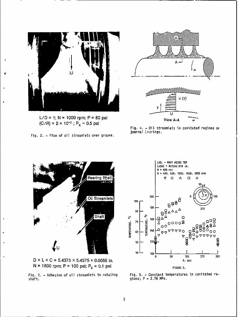
L/D =1; N =1000 rpm; P =60 psi Ve -
(C/R = 2x 1-3 ;ps 0.5psiFig. 4. - Oil streamlets in cavitated regions or
Fig. 2. -Flow of oil streamlets over groove.jora ,ains
LUB. - NAVY #2190 TEPLxDxC , 8x12x0.018 IN.W '1400 psiN = 400, 600, 1000. 1400. 1800 RPM
Bearln,~ U V7 0 & 0 C'
90W
Oi t100 180 -0 80
8 18 0-270
50 1203
40 100 I 3
0 10 9 2 7 6
D xL X C = 5.4375 x 5.4375 x 0.0055 in. e. DEG
N = 1800 rpm; P = 100 psi; P. = 0.1 psi FIGURE 5.
Fig. 3. - Adhesion of oil streamlets to rotating Fig. 5. -Constant temperatures in cavitated re-shaft. gions; P 2.76 MWa.
5
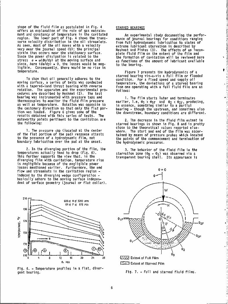
shape of the fluid film as postulated in Fig. 4 STARVED BEARINGSoffers an explanation of the role of gas entrain-ment and constancy of temperature in the cavitated An experimental study documenting the perfor-region. The lower part of Fig. 4 shows the trans- mance of journal bearings for conditions rangingverse velocity distribution In the oil streamlets. from full hydrodynamic lubrication to states ofAs seen, most of the oil moves with a velocity extreme lubricant starvation is described byvery near the journal speed (U); the principal Heshmat and Pinkus (3). The effects of an incom-strain thus occurs near the stationary surface. plete fluid film on the extent of the film andSince the power dissipation is related to the the formation of cavitation will be reviewed herestress c = w(du/dy) at the moving surface and as functions of the amount of lubricant availablesince, here (du/dy) = 0, the losses would be neg- to the bearing.ligible. Consequently, there would be no rise intemperature. Figure 7 presents the hydrodynamics of a
starved bearing vis-a-vis a full film or floodedTo show that oil generally adheres to the condition. For a fixed speed and supply oil
moving surface, a series of tests was conducted temperature, the deviations of a starved bearingwith a tapered-land thrust bearing with reverse from one operating with a full fluid film are asrotation. The apparatus and the experimental pro- follows:cedures are described by Heshmat (2). The testbearing was Instrumented with pressure taps and 1. The film starts later and terminatesthermocouples to monitor the fluid film pressure earlier, i.e, e > elF and e2 < e2F, producing,as well as temperature. Rotation was opposite to in essence, something similar to a partialthe customary direction so that only the flat por- bearing - though the upstream, and sometimes alsotion was loaded. Figure 6 gives some of the the downstream, boundary conditions are different.results obtained with this series of tests. Thenoteworthy points pertinent to the cavitatioN aTe 2. The decrease In the fluid film extent inthe following: starved bearings is shown in Fig. 8 and is pretty
close to the theoretical values reported else-I. The pressure cap (located at the center where. The start and end of the film was ascer-
of the flat portion of the pad) response attests tained by means of pressure probes which locatedto the presence of a hydrodynamic film, not the points of the commencement and termination ofboundary lubrication over the pad at the onset. the hydrodynamic pressures.
2. In the diverging portion of the film, the 3. The behavior of the fluid film in thetemperatures actually tend to drop (Fig. 6). starvation zone (eB - e) was observed via aThis further supports the view that, in the transparent bearing shell. Its appearance isdiverging film with cavitation, temperature riseis negligible because of the negligible powerlosses mentioned earlier. Furthermore, the endflow and streamlets in the cavitation region -
induced by the diverging wedge configuration - gbasically adhere to the moving surface Indeperi- Ident of surface geometry (journal or flat collar).
/ W
210 600 N 3200 RPM64 P 88psi N \
190
150
150 AFO
130 '"
rogi~ ,0 I 'I
110 GOU
0 {1 8 12 16 20 24 28 V/7 Extent of Full FilmO, DEG Extent of Starved Film
Fig. 6. - Temperature profiles in a flat, diver-gent bearing. Fig. 7. - Full and starved fluid films.
6

2700 a. Basic Film Patterne 2
2250 "
..........
/ ,,
Start of U End ofOil Groove Full Film --- Full Film
~~0
30 ° -0
W = 22,240 N (5,000 ,b)/ N = 1800 rpm 0
I SAE 20 Oil
450 1 I I0 0.25 0.50 0.75 b. Pattern During Periodic Pulses
Fig. 9. - Fluid film pattern in starved bearings.
Fig. 8. - Extent of fluid film in starvedbearings.
DYNAMICALLY LOADED BEARINGS
sketched in Fig. 9. As seen, the full film under Film rupture in dynamically loaded bearingsstarved conditions started at more or less a has-been experimentally observed (7-24) to occurconstant angle, (I
8 lF and did not vary along in two general patterns: (1) film rupture alwaysz. The starved zone between the start of the pad exists through the load cycle, and (2) occurrenceand 01F underwent cyclic changes in and disappearance of the film rupture are repeatedappearance. Most of the time, the zone eB 9 ( 9 every load cycle. In the case of a nutatingel was filled with an amorphous mixture of oil, squeeze-film damper, the ruptured film travelsfoam, and gas bubbles (Fig. 9(a)). However, circumferentially ahead of the minimum filmevery 0.5 to 1.0 s, a pulse, originating from the thickness (25).cavitated zone downstream (E > 82), transformedthis region into a pattern of oil streamlets Recent studies by Nakahara et al. (18),(Fig. 9(b)) similar to the conventional Nakal et al. (14), and Natsumeda and Someya (26),downstream cavitation. The pulse frequency was all of whom used special pressure transducerschecked against the journal's rotational (semiconductor strain gauge type) mounted in thefrequency, but no relation nor connection was test journal a, d bearing, report the existence offound between them. However, the pulsating a sharp negative pressure except undar a lightlystreamlets and their frequency were related to loaded condition. Negative pressure (tensile) upthe degree of starvation. The higher the degree to -1.2 MPa, as shown in Fig. 10, was reported byof starvation, the longer the period of pulse Natsumeda and Someya et al. (26). It is concludedfrequency. that the heavier the dynamic load, the greater the
negative pressure. Such a large value has been4. The uIpstream portion of the starved scarcely reported by others. Dyer and Reason
bearing eB E) el filled with an oil and gas (11) reported tensile stress with a maximum valuemixture is shown schematically in Fig. 9(a). of 0.64 MPa. However, their experimental resultsAlthough gaseous bubbles were visible through the showed that the magnitude of tensile stresstransparent bearing, they disappeared in the film decreases as the eccentricity ratio is increased.and had no effect on the streamlets' patterns in Nakahara et al. (18) concluded from their experi-the cavitated zone. ments that cavity pattern changes were caused by
Based on these observations, the model the cavity growth due to the diffusion of dis-provides a reasonably accurate prediction as solved gas in oil under constant speed. Further-given in the literature (1,4-6). more, as reported recently by Walton et al. (25),
7

PsO.2 MPa;, P3.9 Hz; 50 rps; damper grooves exhibited significant flow rever-
0.9; Yt/= 0."2; sals (circumferential feed and drain grooves inthe sealed squeeze film damper). Also, the
__ 07grooves, instead of being full of oil, appeared0.167; =18.5x10 3,.r=0.72 to experience film rupture, which contradicts the
3 435 boundary condition assumption that the groove actsas a large sink. The flow fluctuations in the
3/4%1 damper oil grooves, while not fully explainable,do affect damper perfor'mance and various stages of
1/2 cavitation formation.
2 0 290 It is believed that side entrainment of gas• 0 0.5 ,0 takes place in most of those tribological testI apparatus and sets up various cavitation config-
urations. These discrepancies could be attri-buted, at least partially, to the differences inthe interpretation of the various observations.
145I
0%0
-** CONCLUDING REMARKS
0 0 0 Based on the review of the literature and0results of an experimental investigation, the
following remarks are made:0o O Measuredfrom bearing
J°1Measuredfromjoural I. Side entrainment of the surrounding gashmin to the bearing gap at the downstream position is
.1 1 1 -145 conceivable.0 2C
8, rad 2. The shape of the fluid film in the cavi-tated region is in the form given by Fig. 4. TheFig. 10. - Circumferential pressure distribution fluid adheres by means of weak thin strips to the
of journal bearing under dynamic load (26). stationary surface, but forms a continuous sub-layer on the moving surface. This pattern pre-vails as long as there is an upper pad. Upon
cavity patterns changed with the change of cavity termination of the pad, the tips detach, and thelocations. Both subcavity pressure and radial entire exit flow adheres to the moving surface.flow resistance across the circumferential groove In this region there would be no rise inchanged discontinuously (traveling pressure wave temperature.up to five times that of supplied pressure).
3. Negative pressure (tensile stress) hasDepending on the apparatus and test operating been detected experimentally on the order of
conditions, five or more modes of transitional 1.2 MPa (absolute).phenomena with cavity change were categorized bythe investigators. Various boundary conditions 4. To fully understand and explain a sharphave been used to predict dynamically loaded bear- dent of negative pressure, one needs to considering performdnce. These are Sommerfeld conditions the lubricant as a two-phase liquid consisting offor light load, Reynolds conditions for heavy oil and bubbles of gas and to take into accountload, separation boundary condition for detecting the surface-dilation effect of the surface ten-tensile stress in the oil-film region downstream sion together with tensile strength of the filmof the minimum film thickness position, and in the governing equation of motion.others in order to suit the fulfillment of theexperimental data pattern. While the agreement 5. Under dynamic conditions, other types ofbetween analysis and test is of the right order pressure distributions exist and further exper-of magnitude (depending on the test and boundary imentation and exploration are needed to quantifyconditions assumed) in predicting the extent of the nature of the formation of film rupture.the film rupture zone, analysis does not ade-quately reflect the noted variations in the 6. Careful pressure measurements (from movingboundary conditions observed and does not account and stationary surfaces) of both the staticallyfor the change in the shape of the film rupture and the dynamically loaded journal bearingzone with increasing speed. (although it Is a difficult task) should be
complemented by film temperature measurements inIn a review of experimental results described order to elucidate some of the unresolved aspects
by Walton et al. (25), pressure variations in the of cavitation.
8

CAVITATION IN JOURNAL BEARINGS AND SQUEEZE FILM DAMPERS: EXPERIMENTAL
B. JACOBSON2
EXPERIMENTAL INVESTIGATIONS
In nonstationary bearings, where the minimumfilm thickness moves juring vibration, vapor cavi-tation can appear. This type of -avitaticn is abreakage of the oil or oil-'vearing Interfdcecaused by tensile stre:ses in the lubricant. Itcan appear anywhere in the oil film -- not just atthe outlet where the film thickness is increasingin the direction of the sliding speed.
Vapor cavitation has recently bebi studiedby Jacobson and Hamrock (27,28) and Brewe et al.(29-31) experimentally, theoretically, and numeri-cally. The (.xperiments show 4hat the cavitat'onis Influenced by tne vibration amplitude, thevibration frequency, and the sliding velocity inthe bezring. The clear Influence of the surface ........energy of the bearing surfaces is also apparent; Fig. 11. Test apparatus.cavitation seems to start at the bL~ring surface,if it is made of PFE (polytetrafluoroethylene),or in thr middle of the film, if the surface is a line and entered the bearing at the top left ofmade of steel or PMMA (poly'e'tnylmethacrylate). the PMMA bearing (Fig. 11). On the right of the
test bearing is the motor that gives the slidingIn experiments vapor cavitation occurs when velocity to the roller, and on the left is the
the tensile stress applied to the oil exceeds the motor that gives the squeeze velocity to thetensile stringth of the oil or the binding of the bearing. The speeds of these identical 0.5 kWoil to the surface. The physicel situation neces- motors can vary continuously from 0 to 250 rad/s.sary for vapor cavitation to occur is a squeezingmotion within a bearing. This implie: that the Figure 12 shows the PMMA bearing, which canminimum film thickness is constantly changing in vibrate in a circular motion keeping the axis ofsize and location as a result of the motion vibration parallel to the axis of rotation. Atangential and iormal to the surfaces. special mechanism was manufactured to keep the
centerlines of the bearing and shaft paral'il andExperiments showing vapor cavitation were is also shown in this figure.
first made at Lulea TGchnical Ur,,versity in the
Machine Elements Laboratory and :ater ?t NASA The dynamic eccentricity mechanism can beLewis Research Center. adjusted to give dynamic eccentricity ratios
between 0 and I or in actual measures from 0 toThe geometry of the two test setups was the 0.5 mm. The static eccentricity ratio is set by
same, but the NASA Lewis test apparatus was moving thL motor with the shaft horizontally sostiffer and more precise, both in the measures of that the centerlines of the two motors are offset.the bearings and also in the motion of the PMMAtube and the shafts. Figure 11 shows the NASAtest apparatus with the high-speed camera and thedriving motors for the rotation and vibrationmotions. The high-speed motion picture cameracould take up to 11 000 frames per second withordinary 16-mm motion picture film. In theexperiments here, the framing rates were 1000 and2000 frames per second.
The test bearing was lubricated by gravity I
feed from a can placed approximately 600 mm abovethe bearing. The test lubricant was a nondegassedDexron II automatic transmission fluid with a vis-cosity of 0.066 N.s/m 2 under atmospheric condi-tions. The lubricant passed from the can, through
2Chalmers University of Technology, Goteborg, I 82-3.4.Sweden, and SKF Engineering and Research Centre,Nieuwegein, The Netherlands. Fig. 12. - PMMA-tube and eccentric.
9

]ed
C S(a ) (b ) M c (d ) (0 ) ( g
Fig. 14. - Dynamic cavitation
bubble developed
/W
I lSs
II(C
s
d0.34,
ed 0.66, ws 19.5 rls, and wd!" ed 92 .7 r/s).
%i , vapor cavitation in a journal bearing. The experi-
/ mental conditions in Fig. 14 are length to diame-
ter ratio, 1/4; static eccentricity, 0.34; dynamic
eccentricity, C.66; rotational
speed, ws, 19.5
(I ( da)b ( )( )( e I g
Ses rad/s; and vibration speed, d, 92.7 rad/s. The
ed Cjournal
surface, was made of PTFE, and the camera
ed
framing rate was 2000 frames par second. The timeFig. 13. - Bearing geometries at four different
is less than 25 ms, indic~cing how rapidly the
times; es 0.4; ed - 0.6
vapor cavitation forms and collapses.
Experiments
with steel
journals and w h PTFE
teThtoe14 static eccentricity, 0.34 dynamic 0nd0.mm. eccest ftecetro vbainrmjuntriity sho6w aifrtationaltspeedvitat19.
the center of the journal gives a static load, pattern. For steel journals cavitation bubbles
and the ampltude of vibration
can be varied. start in different
parts of the low pressure
Figur 13 ; ows our p siti ns of thejournal srfartce, as a e Fo PTFE a unalhe ca e
region, depending on where the largest bubble or
Fig r 13. shw Bearin geometi s at f hourrn l dit lessthcln 25Is, ontdc.n ow jral , the
relative to the bearing for a dynamvcally loaded
cavitation seems to start from the same position
journal bearing. The static eccentricity
ratio of the journal for each vibratlon,
which indi-es is set at 0.4, and the dynamic eccentricity
c r s a rp u e o h l -T E I t r a e
mm.o The ofset ofthe c r oThe
eccentricity ratios have a big influence
the ~ ~ ~ ~ ~ ~ ~ ~ ~ ~ centerz of the joralgvevisaiclatatentFrsteion cavtion b h ubble
EXPERIMENTAL RESULTS
to of ths region from start to collapse. For
oata sdems toe cstarfti
(omp e aed pithe
Figure 14 presents seven frames from the high- minimum oul film thickness), no vapor cavitation
speed film showsng the formation and collapse of is found.
10

CATEGORIZATION OF CAVITATION TYPES AND ONSET CONDITIONS
D.M. PARKINS3
Oil films in dynamically loaded journal STEADY FORCE GENERATED BY THE OIL FILMbearings are subject to both translatory andoscillatory squeeze motion of their containing Figure 15 contains data on the magnitude andsurfaces. This discussion deals with oscillatory direction of the steady force (Fst) for eightsqueeze motion only. The principal aim of all cases and from three sources (35,36,41). Eachwork described here is to understand squeeze-film source used the same basic equipment, but other-phenomena - simplified by removing the transla- wise worked completely independently. Some curvestional component. It is important to iistinguish show data obtained with invariant vibratory ampli-sustained oscillatory squeeze motion from "single- tude (ha); one curve shows data obteined withshot movements" in which the oil film containing invariant frequency; and one shows amplitude andsurfaces approach or separate. This paper deals frequency varying together. The data of Fig. 15with the former case. Some published work (32,33) are for initial film thicknesses (yo) from 0.11deals with oscillatory motion in the frequency to 0.73 mm, vibratory amplitudes from 0.0055 torange of 1 to 2 Hz and only the transient first 0 5 mm, frequencies from 5 to 50 Hz, three valuesfew cycles. Other works consider the radial of viscosity. Two values of oscillating surfacesqueeze motion of two circular surfaces, as, for area (A) are included. The use of the steadyexample, in the application of squeeze-film dam-pers to the outer race of rolling-element bear-ings. This discussion deals with oscillatorynormal motion of parallel surfaces at frequenciesin the range likely to be met in machinery, say 5to 50 Hz, and for fully established behavior.
Two of the important aspects of the morerecently identified behavior are
1. A steady force is generated by the oil 4000 / 0(0film subject to normal oscillatory motion of itscontaining surfaces. The possibility was first 3000 1b
suggested by Kauzlarich (34) who gave a theoret-ical treatment for a circular pad using a liquid a. 2000lubricant and a harmonic displacement input. He Z
concluded that inertial forces in the fluid cre- 1000 L(e)ated the steady force. Kauzlarich conducted aqualitative experiment to verify this finding. (),Subsequent experimental work by others (35-37)using nonharmonic oscillatory motion of a square 10plate has confirmed that such a steady force isgenerated, and - over a limited range of param- A2% 30eters - determined the influence thereon of the 0,initial oil film thickness, the oscillatory 4amplitude, and frequency of oscillation. Mostrecently, Kang (38) used a numerical solution Lo 60the Navier-Stokes equation to compute values ofthe steady force.
2. Various regimes of cavitation appearing Curve Ref. Amplitude Initial Fre uency, Pod Lubricantin the oil film due to the oscillatory squeeze of oscillation film Hz area, kinematicha, thickness, m2 viscosity,motion have been identified and characterized, mm Yo, cstogether with the location of the conditions that mmdetermine the onset of cavitation. Reference 39 (a) 35 0.0055 0.11 10to50 625 313gives an initial classification and Ref. 36 fullerdescriptions, all for behavior of an oil film con- (b) 35 .0275 .11 10to50 625 313taned in a square plate. Rodriques (40) predic- (c) 41 .044 .22 20to50 2500 750ted the growth and collapse of central cavitationpatterns in a circular plate. His supporting (d) 41 .044to.66 .22 10to50 2500 313exper,ents were conducted at only one frequency, (e) 36 .4 .73 5to45 2500 370approximately 1.0 Hz - but appear to show cvita-tion patterns which conform exactly to the charac- (f) 36 .4 . 5 to4S 2500 370teristics of that which was later (39) defined as (g) 36 .4 .25 5to45 2500 370regime 2.
(h) 36 .07 to .47 .25 25 2500 3703Cranfield Institute of Technology, College
of Manufacturing, Bedford, MK43 Oal, England. Fig. 15. - Measured steady oil film pressure.
11

pressure Pst Fst/A allows for its effect. typical displacement and pressure time historyReference 42 gives additional values covering with cavitation of an oscillatory cycle for awider ranges. These Include data for a third harmonic force input. The pressure-time historyvalue of oscillatory surface area A and from a is not harmonic. It shows a rapid increase tofourth source (43,44). It is reassuring to maximum pressure followed by a fall to the mini-observe that all the curves In Fig. 15 form a mum value. Regime 2 appears in this part of thecoherent pattern, even though they originate from cycle. A very rapid rise from the minimum pres-separate sources. It is also reassuring to note sure to near atmospheric Is followed by a rela-that the additional data of Ref. 42 would also tively long period near atmospheric pressurefit the coherent pattern If Fig. 15 were vastly before the sharp rise again to maximum pressure.extended. However, the data sparsely cover the Regime 3 appears in this part of the cycle. Theparameter range. It Is analogous to attempting near atmospheric shoulder in the pressure curveto determine the picture of a jigsaw puzzle when of Fig. 16 shows a small positive gradient in theonly a few scattered parts are completed. versions arising when regime 2 alone appears.Clearly, there remains the vital task of con-ducting a complete parametric study over a full The regimes and their subdivisions arerange of variables.
Regime 1. No cavitation at any time in theData from Fig. 15 and Ref. 42 show that, oscillatory cycle.
depending on conditions, the steady force mayeither increase or decrease the surface separa- Regime 2. Cavitation bubbles fed from within thetion. These data also show that thi principal film. Figure 17 is a photograph of ainfluences on the steady force are initial film typical fully developed regime 2thickness (yo), oscillatory amplitude (ha), and cavitation bubble pattern. The bubblesfrequency. The steady force varies directly may contain dissolved gas extractedwith ha and inversely with yo. Cavitation from the solution or vapor of theappeared in many of the cases reported. liquid, or a mixture of both.
CAVITATION REGIMES Regime 3. Cavitation bubbles fed from outside thefilm. Cavitation patterns in this
It is widely established that cavitation may regime may take several forms.arise in such oscillating squeeze films.Rodriques (40) measured and computed cavitation (a) Edge fed: This form is characterizedpatterns with a circular plate oscillating at by smoothly curved bubbles entering1 Hz. May-Miller (39,41) identified three simultaneously from all edges of thecavitating behavioral regimes, which he named square plate. A typical example isregimes 1, 2, and 3. Each regime Is shown in Fig. 18. Some bubbles thereincharacterized by a distinct method of feeding the show the smooth periphery of the bubblebubbles and by the location of the bubbles in the breaking into striations which lead todisplacement and pressure time histories. Exten- the form described in under 3(b).sion of the concept (36,45) shows that regime 3could take several forms. Figure 16 shows a (b) Leaf pattern: This form is character-
ized by a leaf pattern supplied throughFILM THICKNESS a "trunk" that grows inward from the
plate edge (see Fig. 19). Usually one,
tPR ESSURE
R3(a) (bl(c)
R2 or (d)
Fig. 16. - Typical oil film thickness andpressure-time history (with cavitation). Fig. 17. - Reqime 2 cavitation pattern.
12

Fig. 20. Regime 3(c) cavitation bubble pattern.
Fig. 18. - Regime 3(a) cavitation bubble pattern.
but sometimes more such trees appear.Moreover, the tree may grow from adifferent side on different cycles ofthe same condition. References 36 and45 illustrate both of these points.
(c) Leaf pattern with square parameter: Theleaf pattern extends to cover all theoscillating plate surface except for auniform border around three sides(see Fig. 20).
(d) Stream fed: This form is characterizedby a leaf pattern whose perimeterfollows that of the oscillating plate,but with a relatively wide (b/4) clearperimeter. This central leaf pattern isfed by a number of diagonal streams.Figure 21 is a photograph of the fullydeveloped pattern. Fig. 21. - Regime 3(d) cavitation bubble pattern.
Reference 36 gives a sequence of photographsof cavitation patterns at a series of identifiedpoints in the oscillating cycle for regimes 3(a),3(b), and 3(d). In each case the designatedcavitation pattern exists for approximately 0.4 ofthe cycle time. The film is free of bubbles fora similar peric.d. Bubbles advance and withdrawin the remaining time. With regime 3 (whatever
subregime) each rapid increase in film pressurearises when the bubble front crosses the pressuretransducer. The increase from minimum to
atmospheric pressure occurs as the bubble frontadvances, and that from atmospheric to maximumpressure as the bubbles withdraw. An importantfinding in this work (39,41) was the extremely
rapid movement of the bubble front in both" -advance and withdrawal.
Oil depth has a marked effect upon the onsetcavitation patterns (36,45) . Figure 22, which
Fig. 19. - Regime 3(b) cavitation bubble pattern, illustrates this effect, shows the value of
13
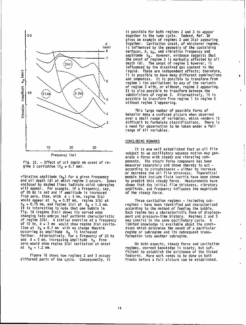
Is possible for both regimes 2 and 3 to appear-2,0 together in the same cycle. Indeed, Ref. 36
gives an example of regimes 2 and 3(a) appearingd together. Cavitation onset, of whichever regime,
(mm) is influenced by the geometry of the containingsurfaces, A, yo, and vibration frequency and
. amplitude ha. However, evidence suggests that7 ?the onset of regime 3 is markedly affected by oil
% 3 (c)- depth (d). The onset of regime 2 however, isinfluenced by the dissolved gas content in theliquid. These are independent effects; therefore,
6 it is possible to have many different combinationsoem and sequences. It is possible to transform from
6 regime 1 (no cavitation) to any of the variantsof regime 3 with, or without, regime 2 appearing.
2 .3( b3 ai\, It is also possible to transform between theE .subdivisions of regime 3. Alternatively, it isE possible to transform from regime 1 to regime 2
without regime 3"appearing.
This large number of possible forms of4 behavior make a confused picture when observed
> over a small range of variables, which renders it3 difficult to formulate classifications. There is
" -, a need for observation to be taken under a fullrange of all variables.
CONCLUDING REMARKS
10 20 30 It is now well established that an oil filmFrequency (hz) subject to an oscillatory squeeze motion may gen-
erate a force with steady and vibrating com-
Fig. 22. - Effect of oil depth on onset of re- ponents. The steaev force component has beengime 3 cavitation (Yo = 0.7 mm). measured separately and shown thereby to act -
according to circumstances - either to increaseor decrease the oil film thickness. Theoretical
vibration amplitude (ha) for a given frequency models that include fluid inertia have been shownand oil depth (d) at which regime 3 occurs. Zones to predict this steady force. Measurements haveenclosed by dashed lines indicate Yihich subregime shown that the initial film thickness, vibratorywill appear. For example, if a frequency, say, amplitude, and frequency influence the magnitudeof 20 Hz is set and if amplitude is increased of the steady force.from zero, then, with d = 3 mm, regime 3(a)would appear at ha = 0.57 mm, regime 3(b) at Three cavitation regimes - including sub-ha = 0.75 mm, and regime 3(c) at ha = 1.3 mm. regimes - have been identified and characterizedIt is interesting to note that one bubble in according to the method of feeding the bubble.Fig. 18 (regime 3(a)) shows its curved edge Each regime has a characteristic form of displace-changing into embryo leaf patterns characteristic ment and pressure-time history. Regimes 2 and 3of regime 3(b). A similar exercise at a frequency may coexist in the same oscillatory cycle. Aof 10 Hz, d = 3 mm would show regime 3(a) cavita- limited knowledge is available about the condi-tion at ha = 0.7 mm with no change therein tions which determine the onset of a particularoccurring as amplitude ha is increased regime or subregime and its subsequent trans-further. Alternatively, for a frequency of 20 Hz formation into another subregime.and d = 5 mm, increasing amplitude ha fromzero would show regime 3(b) cavitation at onset On both aspects, steady force and cavitationat ha = 1.2 mm. regimes, current knowledge is scanty, but suf-
ficient to establish the existence of the listedFigure 16 shows how regimes 2 and 3 occupy features. More work needs to be done on both
different parts of the cycle. Consequently, it fronts before a full picture can be established.
14

CAVITATION IN MICROASPERITY LUBRICATION
A.O. LEBECK4
It is well known that, even when sliders are Lo. -Bearingtonmade parallel and slide parallel in a lubricating o. seal - pPressureveselfilm, fluid pressure load support develops so as -to support some or a1l of the load and reducefriction. Lebeck (46,47) reviewed this behavior,the experimental data, and the mechanisms ind e t a i l .,,,,du,° r - S t ato r
A typical example of such behavior is shown bem-a , dowel
in Fig. 23. The friction of carbon graphite pins Torque R
sliding on tungsten carbide in water was measured arm
using the apparatus shown in Fig. 24. The fric-tion coefficient at first decreases with increas-ing duty parameter and then later increases. Thedecrease is caused by what are apparently hydro-,,dynamic pressures building up and reducing con-tact friction. The later increase is, of course,caused by viscous friction. Fig. 24. Hydrostatic bearing assembly diagram
For many years it has been thought thatmicroasperities serve as a source of fluid pres-sure load support in mechanical seals and parallelsliding lubricated contacts as reported in theexperiments by Kojabashian, Richardson (48), andHamilton (49). Figure 25 shows how microasperi- -___\\\\\\\
ties produce load support. Cavitation at thedownstream side is essential to get a net loadsupport. As Kojabashian and Richardson (48) show,one can predict that a theoretically significant PRESSUREload support will develop on a seal-like surfacewhich has many microasperities.
rpambExperimental tests of this idea show that,
if the ambient pressure is raised well above thecavitation pressure, no net load support results - - ------(Fig. 26). It follows that friction should LPCVITATION
oo _Fig. 25. - Truncated asperity pressure distribu-tion.
0 A
~.0
0U. 2 0 TEST I. TEST 2 0
OPEN SYMBOLS - CLOCKWISE T PRESSURESOLID SYMBOLS - COUNTERCLOCKWISE
10-10
109
10-8
107
106
105 'Pare
Fig. 23. - Parallel sliding in water.
LCAVITATION4Mechanical Seal Technology Inc., Albuquer-
que, NM. Fig. 26. - Zero load support.
15

20 increase because a lower fraction of the load isbeing supported by microasperities. This can beverified using the theory of Hamilton et al. (50).
15R To test this hypothesis, Kanas (51) ran a series3of experiments, using the apparatus shown in
Fig. 24, where friction was carefully measured as10 a function of ambient pressure. His results (see
Fig. 27) show no significant increase in frictionwith increasing ambient pressure. Similar results
5 were obtained at higher speeds.Thus, in water, under the siding conditions__j noted, and at a condition of (from Fig. 23) con-
0 50 100 150 200 250 300 350 siderable fluid pressure load support, micro-AMBIENT PRESSURE. Psi asperity lubrication, or any other mechanism that
relies on cavitation, does not appear to be aFig. 27. - Friction torque versus ambient pres- primary source of load support.sure. Carbon pressure, 300 psi. Each pointrepresents an average of 450 samples.
16

CAVITATION EROSION DAMAGE IN ENGINE BEARINGS
F.A. MARTINS
The experiences discussed in the 1979 paper,
"Cavitation Erosion Damage in Engine Bearings:Theory and Practice," by Garner, James, andWarriner (52) still reflect much of the currentview on the subject. A few selected extractsfrom that paper are presented here. Theseinclude examples of typical cavitation erosion Original Depression on Fluid flows Formationbubble sidse Opposite into growing ofdamage, together with suggested mechanism of shape soid suace depression mnro-etdamage. Commonly applied palliatives and theireffectiveness, based on engine experience, are Fig. 28. - Mechanism of micro-jet formation (52).also discussed.
"Cavitation erosion in engine bearings is a "In fully grooved bearings, the damage occursphenomenon which has assumed increasing signi- predominantly at the groove edges, but canficance during the past...years, probably as ultimately spread into the bearing lands. Thereresult of the design trends towards higher is strong evidence that the damage is caused byrotational speeds and, in some cases, higher inertia effects on the column of oil In therates of change of cylinder pressure... connecting rod drilling which is supplied from
the large-end bearing groove to provide top end...Damage is seen predominantly in diesel lubrication and piston cooling..."
engine bearings, and on the rare occasions whendamage occurs in gasoline engines it is normally The damage may be cured by restricting theas a result of operating under (incorrect back flow from the rod drilling into the bearingconditions). (fitting a nonreturn valve has been one solution).
In other cases, "the damage was diminished when"In many cases the damage is restricted to the groove cross-sectional areas In both the main
local attack of the overlay and the performance and large-end bearings were increased, thusof the bearing is virtually unaffected... allowing the oil column fluctuation to be betterHowever, in more extreme cases extensive loss of absorbed by the oil in the grooves ....overlay and interlayer material occurs, and theconsequential adverse effects upon oil film cond- "On partially grooved large end bearingsitions will reduce the service reliability and damage frequently occurs at the groove run-out,life of the bearings.., either at the end of the partial groove, or at
the side of the run-out, [Fig. 29]. The problem"The fact that diesel engine bearings are occurs at the end of the partial groove in the
more prone to cavitation erosion damage is attrn- direction of shaft rotation, regardless of thebuted to the more severe combustion conditions, position of the oil feed connection to the rodand, additionally, to the necessity for more drilling. In the example shown in (Fig. 29), incomplex oil feeding arrangements with greater which the damage had occurred within 400 hours,chance of flow discontinuities."
Garner et al. state that cavitation erosiondamage is associated with the collapse of vaporouscavities near to the bearing surface and suggestthat the mechanism is the impingement by micro-jets of fluid. They describe a possible sequenceof eVents in the collapse of vaporous cavitiesleading to the formation of high intensity micro-jets (see Fig. 28). Let us now look at the resultof this in terms of actual damaged bearings.
LARGE-END BEARING DAMAGE PREDOMINANTLY ASSOCIATEDWITH OIL IN CONNECTING ROD DRILLING
"The commonest form of damage occurring inlarge end bearings appears at first sight to bedue more to flow erosion than to cavity collapse,
but detailed examination of the damage confirms acavitation effect. This can occur in either_ _ _
fully grooved or partially grooved bearings.Fig. 29. - Cavitation damage associated with
sTribology Consultant to The Glacier Metal groove run-out in large-end bearing, togetherCompany, Limited, Middlesex, EnglanC. with effective solution (52).
17

the oil feed to the rod was adjacent to thedamaged groove ending. The problem was overcomeby the simple expedient of drilling a radial holein the run-out section, as shown by the lowerbearing in [Fig. 29] which had run for 1500 hours.Several other cases of similar damage have beensuccessfully treated, .. .either by provision of aradial hole or by terminating the groove (a) \ ( (cconveniently at the end of a bridge-piece slot." Cavitles Cavitiesformed collapsed
Fig. 31. - Cavity formation associated with inter-MAIN BEARING DAMAGE PREDOMINANTL'," ASSOCIATED WITH action between journal drilling and partialOIL IN CRANKSHAFT DRILLING groove (52).
"The majority of modern medik speed dieselengines use partially grooved main bearingq inwhich the ungrooved arc is symmetrically placed was slow. Bearings In this condition afterin the bottom half, and is approximately 1200 in several thousand hours operation may quite safelyextent. Such bearings provide an acceptable oil be refitted. However, in some instances thefilm thickness within the narrow confines dictated damage can be much more severe...by the overall design, but, at todaj's high ra-tings, are those most likely to suffer from cavi- "It is probable that as the oil drilling intation erosion damage. This occurs downstream of the shaft traverses the groove run-out, cavitiesbut usually close to, the groove runout and are formed at the intersection of groove run-outtypically takes the form shown in [Fig. 30]. edge and the oil hole blend radius, as depicted
diagrammatically in [Fig. 31).""In this Instance, the damage was found after only400 hours of operation, and was restricted to the "Various palliatives have been tried onsoft overlay plated surface of the bearing, which different engine types to alleviate this type ofwas of the order of 0.03 mm thick. The stronger damage. These have usually consisted of modifi-bearing lining underneath had not been attacked. cations to the end of the partial groove. TheThis form of damage is characterized by a crescent most effective palliative so far adopted has beenform... In the particular example shown, after a tangential blend from groove to bearing surfacethe initial short termn damage, further progression with a square profile ((Fig. 32))."
900
Tangential groove runout
Fig. 30. - Mild overlay damage in partially Fig. 32. - Design detail of successfully appliedgrooved main bearing (52). modification to groove ending (52).
18

Polar load diagram Journal center locus
B -D
Ruptured regions(a)
-0
0 180 360Bearing angle
Ruptured regions
(b)
Fig. 33. - Suction damage in large-end bearing as-sociated with large clearance (52).
MAIN AND LARGE END BEARING DAMAGE PREDOMINANTLYASSOCIATED WITH RAPID SHAFT MOTION 2
- 225 0Cavitation erosion damage of the type shown 215
in CFit 33] (commonly referred to as suction 0 180 360cavitation erosion) occurs in the center of the Bearinganglelands in some fully grooved bearings. It is due ( r)to rapid shaft movement away from the bearing (csurface and is worse with large clearances. It Fig. 34. - Predicted hydrodynamic conditions asso-occurs in the upper half of high-speed diesel ciated with occurrence of cavity damage (52).main bearings (and also in a large end bearingduring a series of development tests on a mediumspeed two stroke engine).
that a rapid journal movement takes place betweenPrediction of the journal orbit and exam- points B and C. Whilst experience suggests that
ination of the hydrodynamic conditions within the rapid fluctuations in pressure are associatedbearing helps to pinpoint the area of likely with such movements, the initial plot of rupturedamage. It also enables the designer to quickly zones within the bearing ([Fig. 34(b)) failed toexamine the relative merits and disadvantages of show anything significant at the top of thevarious designs. "For the purposes of balancing bearing (0 or 3600) where damage occurred. Itloads and integrated pressures, i.e., in pre- was only when the time step of the solution wasdicting the journal center orbit, it has been refined (from 10° to 1° crank angle) that intenseassumed, as is common practice, that negative "negative" pressure zones were predictedpressures cannot be sustained by the lubricant. ([Fig. 34(c)])." The position of the maximumHowever, it is considered that predicted negative negative pressure corresponded to the position ofpressures wiii indicate the position and inten- cavitation damage on the bearing surface, thussity of any cavity formation." indicating that the cause of the damage was
cavity formation (and subsequent collapse). TheThis method was used to examine the hydro- palliative here was to reduce the bearing clear-
dynamic conditions of a center main bearing ance which alleviated the damage. However, Itshowing the same type of damage as shown in may be necessary in other instances to modify theFig. 33. "The load diagram and resulting orbit polar load diagram. For example, the counter-are shown in [Fig. 34(a)], and it can be seen weights could be changed.
19

CONCLUDING REMARKS Relatively simple modifications to thedetail design of the bearing and its associated
Cavitation erosion damage in diesel engine components can usually obviate problems from thebearinos appears to fall broadly into three cate- first two categories, but often not from thegories, isociated with third. However, these more intractable problems
do seem to show some correlation with predicted1. oil in crankshaft drillings and bearing oil film conditions. A more detailed theory than
oil feed features that considered here will probably be neededbefore damage can be reliably predicted at the
2. Effects of the oil within the connecting design stage.rod drillings
3. Journal movements within the bearingclearance space leading to adverse oil filmconditions.
20
REFERENCES
1. Cole, J.A., and Hughes, C.J., "Oil Flow and Bearings (1st report) -- The RelationFilm Extent in Complete Journal Bearings," Between the Behavior of Cavities and theProc. Inst. Mech. Eng., 170, 499-510 (1956). Pressure Distribution Curve," 3. Jpn. Soc.
Lubr. Eng., 27, 837-844 (1982).2. Heshmat, H., "On the Mechanism of Operation
of Flat Land Bearings," Interface Dynamics, 15. Pan, C.H.T., "Dynamic Analysis of Rupture inD. Dowson, C.M. Taylor, M. Godet, and Thin Fluid Films. I - A Noninertial Theory,"D. Berthe, eds., Elsevier, New York, J. Lubr. Technol., 105, 96-104 (1983).149-160 (1988).
16. Parkins, D.W., and May-Miller R., "Cavitation3. Heshmat, H., and Pinkus, 0., "Performance of in an Oscillatory Oil Squeeze Film," 3. Tr-
Starved Journal Bearings with Oil Ring Lu- bology, 106, 360-367 (1984).brication," J. Tribology, 107, 23-31 (1985).
17. Kawase, T., and Someya, T., "An Investigation4. Articles, A., and Heshmat, H., "Analysis of into the Oil Film Pressure Distribution in
Starved Journal Bearings Including Tempera- Dynamically Loaded Journal Bearing," 4thture and Cavitation Effects," J. Tribology, European Tribology Congress, Vol. II,107, 1-13 (1985). 5.2.3. (1985).
5. Heshmat, H., "Theoretical and Experimental 18. Nakahar, T., Terasawa, T., and Aoki, H.,Investigation of Oil Ring Bearings," EPRI, "Transition PHenomena of Gaseous CavitationRotating Machinery Dynamics, Bearing and in Thin Oil Film Betwee Non-Parallel FlatSoals Symposium, September (1986). Surfaces," Proc. JSLE I':ern. Tribology
Conf., Vol. 3, Elsevier, New York,6. Heshmat, H., and Pinkus, 0., "Mixing Inlet 1097-1102 (1985).
Temperatures in Hydrodynamic Bearings,"J. Tribology, 108, 231-248 (1986). 19. Brewe, D.E., "Theoretical Modeling of the
Vapor Cavitation in Dynamically Loaded7. Jakobsson, B., and Fioberg, L., "The Finite Journal Bearings," NASA TM-87076/USAAVSCOM
Journal Bearing, Considering Vaporization," TR 85-C-15, and J. Tribology, 108, 628-637Trans. Chalmers Univ. Technology, Goteborg, (1986).Sweden, 190 (1957).
20. Hashimoto, H., and Wada, S., "The Effects of8. Olsson, K., "Cavitation in Dynamically Loaded Fluid Inertia Forces in Parallel Circular
Bearings," Trans. Chalmers Univ. Technology, Squeeze Film Bearings Lubricated withGoteborg, Sweden, 308 (1965). Pseudo-Plastic Fluids," 3. Tribology, 108,
282-287 (1986).9. Wakuri, Y., Tsuge, M., Nitta, Y., and
Sanui, Y., "Oil Flow in Short-Bearing with 21. Elrod, H.G., "A Cavitation Algorithm, "3.Circumferential Grove," Bull. JSME, 16, Lubr. Technol., 103, 350-354 (1981).441-446 (1973).
22. Orcutt, F.K., "An Investigation of the Oper-10. Fall, C., "A Study of Cavitation, and the ation and Failure of Mechanical Face Seals,"
Phenomenon of Ribbing, in Steady, Hydro- 3. Lubr. Technol., 91, 713-725 (1969).dynamic Thin-Film Flow," Ph.D. Thesis,Leeds University, (1976). 23. Hughes, W.F., Hinowich, N.S., Birchak, N.J.,
and Kennedy, M.C., "Phase Change in Liquid1]. Dyer, D. and Reason, B.R., "A Study of Face Seals," J. Lubr. Technol., 100, 74-80
Tensile Stresses in a Journal-Bearing Oil (1978).Film," J. Mech. Eng. Sci., 46-52 (1976).
24. Findlay, J.A., "Cavitation in Mechanical Face12. Savage, M.D., "Cavitation in Lubrication; Seals," J. Lubr. Technol., 90, 356-364
Part 1. On Boundary Conditions, and Cavity- (1968).Fluid Interfaces; Part 2. Analysis of NavyInterfaces," 3. Fluid Mech., 80, 743-768 25. Walton, J.F., II, Malowit, J.A., Zorzi, E.S.,(1977). and Schrand, 3., "Experimental Observation
of Cavitating Squeeze-Film Dampers," 3. Tr-13. Pan, C.H.T., "An improved Short Bearing Anaiy- bo1ogv, 109, 290-295 (1987).
sis for the Submerged Operation of PlainJournal Bearings and Squeeze-Film Dampers," 26. Natsumeda, S., and Someva, T., "Negative Pres-3. Lubr. Technol., 102, 320-332 (1980). sures in Statically and Dynamically Loaded
Journal Bearings," Fluid Film Lubrication -14. Nakal, M., Kazamaki, T., and Hatake, T., Osborne Reynolds Centenary, D. Dowson, C.M.
"Study on Pressure Distribution in the Taylor, M. Godet, and D. Berthe, eds.,Range of Negative Pressure in Sliding Elsevier, New York, 65-72 (1988).
21

27. Jacobson, B.O., and Hamrock, B "., "High-Speed with Experimental Results," Ph.D. Thesis,Motion Picture Camera Experiments of Cavita- Cornell University, June (1970).tion in Dynamically Loaded Journal Bear-ings," J. Lubr. Technol., 105, 446-452 and 41. May-Miller, R., "An Investigation of Cavita-NASA TM-82798 (1983). tion in a Liquid Squeeze Film," MSc Thesis,
Cranfield Institute of Technology (1982).
28. Jacobson, B.O., and Hamrock, B.J., "Vapor
Cavitation in Dynamically Loaded Journal 42. Parkins, D.W., "Oscillatory Oil SqueezeBearings," 2nd Intern. Conf. on Cavitation, Films," Proc. Institute of Mechanical Engi-Mechanical Engineering Publications, neers, London, Tribology - Friction, Lubri-England, 113-140 and NASA TM-83366 (1983). cation and Wear - 50 Years On, Vol. 1,
Mechanical Engineering Publications,29. Brewe, D.E., Hamrock, B.J., and Jacobson, Suffolk, England, 27-36 (1987).
B.O., "Theoretical and Experimental Com-parison of Vapor Cavitation in Dynamically 43. Stanley, W.T., "Dynamic Characteristics of anLoaded Journal Bearings," Intern. Symp. on Oil Squeeze Film," MS: Thesis, CranfieldCavitation, Senda!, Japan, Apr. 16-19 and Institute of Technology (1981).NASA TM-87121/USAAVSCOM-TR-85-C-19 (1986). 44. Kahangwa, B., "Squeeze..Film Forces in Oil
30. Brewe, D.E., and Jacobson, B.O., "The Effect Films," M.Sc. Thesis, Cranfield Instituteof Vibration Amplitude on Vapour Cavitation of Technology (1979).In Journal Bearings," Wear, 115, 63-73 andNASA TM-88826/IISAAVSCOM-TR-86-C-26 (1987). 45. Woollam, J.H., "An Analysis of the Vibratory
Characteristics of an Oil Squeeze Film,"31. Brewe, D.E., and Khonsari, M.M., "Effect of M.Sc. Thesis, Cranfield Institute of
Shaft Frequency on Cavitation in a Journal Technology (1984).Bearing for Noncentered Circular Whirl,"Tribology Trans., 31, 54-60 (1980). 46. Lebeck, A.O., "Parallel Sliding Load Support
in the Mixed Friction Regime, Part I - The32. Kuroda, S., and Hori, Y., "An Experimental Experimental Data," J. Tribology, 109,
Study on Cavitation and Tensile Stress in a 198-195 (1987).Squeeze Film," J. Jpn. Soc. Lubr. Eng., 23,436-442 (1978). 47. Lebeck, A.O., "Parallel Sliding Load Support
in the Mixed Friction Regime, Part 2 -33. Hays, D.F., "Squeeze Films for Rectangular Evaluation of the Mechanisms," J. Tr -
Plates," J. Basic Eng., 85, 243-246 (1963). bology, 109, 196-206 (1987).
34. Kauzlarich, J.J., "Hydraulic Squeeze 48. Kojabashian, C., and Richardson, H.H., "ABearing," ASLE Trans., 15, 37-44 (1972). Micropad Model for the Hydrodynamic Perfor-
mance of Carbon Face Seals," Proc. Third35. Parkins, D.M., and Stanley, W.T., "Charac- Intern. Conf. on Fluid Sealing, Cambridge,
teristics of an Cil Squeeze Film," J. Lubr. England, BERA, Paper E4 (1967).Technol., 104, 497-503 (1982).
49. Hamilton, D.B., "Final Summary Report on the36. Parkins, D.W., and Woollam, J.H., "Behavior Dynamic Behavior of Liquid Lubricated Face
of an Oscillating Oil Squeeze Film," J. Seals to the Rotary Shaft Seal ResearchTribology, 108, 639-644 (1986). Group," Battelle Memorial Institute,
Columbus, OH, Feb. 22, 14 (1965).37. Parkins, D.W., and Kahangwa, B., "Forces Gen-
erated by an Oil Squeeze Film," ASME Paper 50. Hamilton, D.B., Walowit, J.A., and Allen,80-C-2 Lub-39, (1980). C.M., "A Theory of Lubrication by Micro-
irregularities," J. Basic Eng., 88,38. Kang, Byung-Hoo, "Prediction of an Oscilla- 177-185 (1966).
tory Oil Squeeze Film Behavior." M.Sc.Thesis, Cranfield Institute of Technology, 51. Kanas, P.W., "Microasperity Lubrication in a(1986). Boundary Lubricated Interface," Masters
Thesis, Mechanical Engineering Dept., Univ.39. Parkins, D.W., and May-Miller, R., "Cavitation of New Mexico (1984).
in an Oscillatory Oil Squeeze Film," J. Trn-o, 106, 360-367 (1914). 52. Garner, D.R., James, R.D., and Warriner, J.F.,
"Cavitation Erosion Damage in Engine Bear-40. Rodriques, A.N., "An Analysis of Cavitation ing: Theory and Practice," J. Eno. Power,
in a Circular Squeeze Film and Correlation 102, 847-857 (1980).
22

PART II
THEORETICAL MODELING AND PERFORMANCE
23
S I

INTRODUCTION much 1. the GUmbel conditions in which so'utionswere ob ied to the Reynolds equation, and the
In part I, we were made aware of the numer- cavitat' was determined by disallowing the exist-ous ways that cavitation could be manifested and_ ence of • jamblent pressures. However, dynamicof the categorization thereof. In particular, cav- loading uauses changes in the local film thick-itation can either be the result of (a) dissolved ness, which leads to nonstationary cavitation;gas coming out of solution or (b) evaporation that is, the cavitation boundary is in motion(flashing) of the fluid. Both types of cavitation This motion is manifested as the growth andare commonly observed in journal bearinqq, collapse of the bubble as well as downstream trans-squeeze-film dampers, connecting rod bearings, and port from the minimum film position. The appropri-pistons. Both hav a pronounced effect ..n their ate boundary condition may require a conditionoperation. The oc irrence of cavitation in jour- other than a zero-pressure gradient at the bound-nal bearings (I) results in reduced power loss, ary. The studies of Olsson (8,9) suggest that thefriction coefficient, bearing torque, and load usual Swift-Stieber film-rupture condition is ade-capacity. Dowson and Taylor (2), in an excellent quate for dynamic situations if the cavitationreview of cavitation, point out that cavitation boundary moves at a speed that is less than halfneed not have a deleterious effect on the load- the journal surface speed. It seems highly un''ke-carrying capacity of bearings. Horsnell's calcula- ly that this condition would be met during the ini-tions (3) on load capacity for steady-state condi- tial stages of growth and the last stages of bubbletions show that, if cavitation is not considered, collapse.the load can increase threefold over the predictedload. Jakobsson-Floberg (1) and Osson (8)
formulated boundary conditions for a moving bound-In recent years imposing higher loads and ary that conserved mass within the cavitated
speed together with more complicated loading region as well as at the boundary (commonlycycles resulted in bearings experiencing cavita- referred to as the JFO cavitation theory). It wastion erosion damage, as discussed in the article assumed that liquid was convected through the cavi-by F.A. Martin in part I. In addition to the cavi- tated region in the form of striations extended totation damage, there is the damage that can occur both surfaces in the film gap. There is evidencedue to self-excited instabilities that are encoun- that some liquid is transported in the form of antered under dynamic loading. These instabilities adhered layer to the fa. er surface (10,11). Pancan be manifested as a whirling or whipping motion (12) has broadened the JFO theory to accommodate(4) of the journal center. Large vibrational those situations in which the mass transportamp]i udes can result in large forces being trans- through the cavitated region is not necessarilymitted to the system. A designer can circumvent via liquid striations. For moderately to heavilythat problem, or at least the severity of it, by loaded bearings (i.e., for a load-carryingknowing the speed threshold at which it occurs. capacity much greater than the surface tensionThis information is often obtained by referring to forces of the lubricant), the adhered layer can be"stability maps" (5,6). Stability maps require neglected (10). The striated flow in the JFOthe determination of hydrodynamic force terms cou- theory is necessarily a Couette flow because of apled to the dynamical equations of motion. constant-pressure assumption within the cavitated
region. Jakobsson and Floberg's experimental find-The calculation of the hydrodynamic force com- ings (1) support the constant-pressure assumption.
ponents is dependent on the film model used, espe-cially at high eccentricities. Many of the film However, Etsion and Ludwig (11) have measuredmodels that are used to generate stability maps pressure variations of the order of 50 kPa insideinvolve theories that are overly restrictive a gaseous cavitation bubble. To resolve this(e.g., narrow bearing theory, infinite bearing apparent contradiction, one must know whether thetheory) and treat the cavitation in a very superfi- cavitation bubble is gaseous or vaporous. Etsioncial way. Notable of these is the ir-film cavita- (11) provides a plausible mechanism for determin-tion theory in which positive pressures extend ing this, based on liberation and reabsorptionthrough half the circumference of the bearing and rates between a gas and a liquid. The same argu-the other half is regarded as cavitated. This ments for pressure variation within a vapor bubbleboundary condition violates the conservation of would not apply (13). In view of this discussion,mass. Specifying zero-pressure gradient and cavi- the constant pressure assumption for vapor cavita-tation pressure at the boundary (i.e., Reynolds or tion seems reasonable. Despite some of the contro-Swift-Stieber boundary conditions) represents the versy and certain lack of understanding, the JFOconditions for film rupture in a reasonable way theory perhaps represents one of the best accountsbut does not properly represent the conditions of a dynamical theory to date of moderately towhen the film is reestablished. While this .ound- heavily loaded journal bearings and/or dampers.ary condition may yield satisfactory result. for a It is an improvement over the Swift-Stleber condi-steadily loaded bearing, it leads to inaccuracies tions, even for steady-state solutions, because itin situations where the bea,ing is dynamically provides for film reformation as well as filmloaded (7). In actual practice, the Swift-Stieber rupture. Both rupture and reformation renuire aconditions are often compromised as a matter of knowledge of the pressure gradient and frtctionalconvenience by neglecting the implementation of film content at the Interface to determine itsthe zero-pressure gradient condition. This is location. Unlike a rupture boundary, the reform-
25
atlon boundary is subjected to a pressure flow between grid points and to evaluate the required(i.e., nonzero pressure gradient). pressure derivative. Later, Elrod (15) modified
it and presented it in more detail. Rowe andFurthermore, the fractional film content at Chong (16) Improvised the Elrod algorithm so that
the boundary is determined by a residual fluid pressure Is the dependent variable rather thanwithin the cavitated region that has been released fractional film content. Provision was made forat a rupture boundary (earlier In time) and gov- pressure sources as well as automatic switchingerned by the fluid transport law. Which condition for full and cavitated regions. Miranda (17) was(reformation or rupture) prevails depends on the one of the first to apply this method for steadilyrelative mction of the boundary with the motlon loaded axial groove journal bearings. The fullof the convected fluid normal to the boundary. potential of the algorithm did not materializeTypically, under steady-state cavitating con- until Brewe (7) applied It to nonstationary cavi-ditions, the rupture boundary occurs along the tation in a Jo,irnal bearing undergoing noncenteredupstream boundary, and the reformation boundary circular whirl. For other bearing and seal appli-occurs along the downstream end. Under dynamic cations using the Elrod algorithm, the reader isloading and nonstationary cavitation, rupture referred to In (18-26).or reformation conditions may be required ateither the upstream or the downstream boundary. This work represents a summary of the state-The programming task to effect these conditions of-the-art and Is by no means complete. Recentlyin a computational algorithm is exceedingly newer ideas and methodologies have emerged thattedious. In current practice this discourages contribute to the present methods and techniquestheir Implementation. of numerical modeling. We are sincerely grateful
to the contributors of this composition in present-The Elrod and Adams (14) computation scheme, Ing many of their innovations, ideas, and Insights
which mimics the JFO theory, avoids the complex to this complicated problem.programming required to trace the moving boundary
26

NOMENCLATURE
Al First Rivlin-Ericksen tensor, s- I R Bearing or journal radius, m
A2 Second Rivlin-Ericksen tensor, s-2 r Radius of flat bubble, m
C Bearing radial clearance, i s Marking parameter in time, s
Cij Damping matrix, N.slm T Temperature, °C
D Bearing diameter, m ATv,l Temperature change from oil vapor to
e Eccentricity, m liquid, OC
F Total fluid force, N i Stress tensor
F(s) Deformation gradient history t Time, s
f Dynamic fluid force, N U Surface velocity in x direction, and/or
fA Adhered-film fill factor sliding velocity, m/s
g Switch function u Velocity of the fluid in the
H Nondimensional film thickness, (h/C) circumferential direction, m/s
HA Nondimensional adhered film thickness V Collapse velocity of the bubble, m/s
4h Film thickness, m v Velocity vector, m/s
hC Film coeficient of heat transfer for condens- W Applied static load on bearing, N; width ofing oil vapor at low flow velocity, N/m. C2 cavitation bubble, m
I Last grid point X Nondimensional x-coordinate, x/R
I Grid point index x Coordinate in circumferential direction, m;instantaneous position coordinate relative
Kij Stiffness matrix, N/m to journal center, m
L Length of bearing in z-direction, m xs Vertical displacement of journal center rel-ative to bearing center, rn
L' Axial halflength (L' - 1/2L), m
S Instantaneous position coordinate relativeIv Heat of vaporization, kJ/kg to bearing center, m
N Total number of time steps * Instantaneous x-component of journal veloc-ity, rn/s
n Iteration level
Y Nondimensional y-coordinate, y/Rn Unit normal vector of the internal
boundary
y Coordinate in radial or normal direction, m;OB Bearing center instantaneous position coordinate relative
to journal center, mOj Journal center2 Instantaneous y-component of journal veloc-
P Nondimensional pressure, p/i(C/R)2 ity, m/s
p Fluid pressure, N/m2 y Instantaneous position coordinate relative
to bearing center, mPvap Vapor pressure, N/m2
Pa Atmospheric pressure, N/m2 Ys Horizontal displacement of journal centerrelative to bearing center, m
Q Sweeping flux vector, m2/s Z Nondimensional z-coordinate, z/L'
QZL Nondimensional axial flow z Coordinate in axial direction, m
27

Zc Location of bubble, m t Period of dynamic load; the Instant the ad-
hered film was formed at the breakup point;
ze Axial location of the cavitation boundary, m former instant in time, s
Zm 1/2 Bearing width, m txy Shear stress, N/m2
Inclination of unit normal (n) to direction @ Attitude angle, rad.of sliding, rad; non-Newtonian materialparameter, N.s/m 2 Film flux, m21s
Lquid bulk modulus, N/m2; non-Newtonian X Inverse function for the spatial position x,material parameter, N.s2/m2 m
y Nondimensioned counterpart to the material Xt Relative deformation functionparameter a, (aU/IR) ' Liquid phase transport flux, m2/s
S Central difference operator; nondimensionedcounterpart to the material parameter 3, qe Circumferential transport flow, m3/s(603U2 /pC2) 'z Axial pressure flow, m3/5
c Ecc(wh ricity ratio of bearing (e/C)cr Angular velocity of shaft, rad/s
S Position of upstream cavitation boundary atany axial position, m
r Unwrapped circumferential coordinate along Subscriptsthe cylindrical bearing surface, m
a Surface ae Nondimensional density in full film, (plpc);
fractional film content in cavitation region b Surface h
(n Fill factor of adhered layer on sliding B Bearingsurface
c CavitationeB Bridged fill factor
d Dynamicec Fill factor of layer clung to stationary
surface F Full fluid film
> Ratio of bearing half length to bearing ra- j Journaldius, (L'/R o)
max MaximumP Viscosity, N.s/m 2
Ia Artificial viscosity, N.s/m2 mm Minimum
S StarvationS Positional variable, m; Axial coordinate of
the cylindrical bearing surface, m s Static, supply
P Density of saturated oil vapor, kg/m 3 w Waist
28

DEVELOPMENT AND EVALUATION OF A CAVITATION ALGORITHM
T.G. KEITH' AND D. VIJAYARAGHAVAN'
The effects of cavitation on performance have function to eliminate the pressure term In thelargely been disregarded in bearing performaoce cavitation region. Elrod pointed out that thecalculations. For years, common practice was to algorithm was developed "after considerablemodify full-film results in load calculations by experimentation" and therefore does not presentsetting all predicted negative pressures to the development details. Accordingly, it does notcavitation pressure (the half-Sommerfeld or GUmbel readily lend itself to improvement.boundary conditions). Albeit this produced reason-able load values, it is also well known that the An attempt is made here to develop an algo-results violated the conservation of mass princi- rithm that is as effective as the Elrod algorithmple. In more recent procedures the film pressure in predicting cavitation in bearings. The pro-is assumed to develop from the point of maximum posed algorithm has the same objectives as thefilm thickness and end where the pressure deriva- Elrod algorithm but is developed without resortingtive vanisnes (the Reynolds or Swift-Stieber bound- to trial and error. Hopefully, this developmentary condition). Film rupture is more appropriately will serve as a platform upon which further algo-treated, but reformation of the film is essentially rithm improvement can occur.neglected.
ANALYTICAL FORMULATIONJacobsson and Floberg (1) and Olsson (7), pro-
posed a set of self-consistent boundary conditions The two-dimensional, transient form offor cavitation to be applied to the Reynolds equa- Reynolds equation for a Newtonian lubricant in lam-tion. The boundary conditions properly account inar flow, allowing for compressibility effects,for mass conservation in the cavitation region, can be written asThe collective procedure is now generally termedJFO theory. This theory, when applied to moder- 8ph a(_hU ph3 BP\ a- ( h3 8"\ pI]ately to heavily loaded journal bearings, produced + ax\ 2 - 2a + 2
values that were in satisfactory agreement with
experimental values. The theory markedly improved This is an expression of the conservation ofthe prediction of cavitation regions in bearing mass: the first term on the left is the squeezeanalyses and for transient problems. term; the second is the net mass flow rate in the
x (flow) direction; and the third is the net massElrod and Adams (13) introduced a computa- flow rate in the z (axial) direction. Note that
tional scheme that incorporates JFO theory in a the flow rate in the x direction consists of a con-very simple manner. This procedure avoids the com- tribution due to shear (Couette flow) and a contri-plexities of locating film rupture and reformation bution due to pressure gradient (Poiseuille flow);boundaries as it automatically predicts cavitation whereas, the flow rate in the z-direction isregions. Later Elrod (14) modified the finite dif- solely due to pressure.ference portion of the procedure to provide betterresults. The procedure, now generally termed the The density of the lubricant Is related toElrod cavitation algorithm, has the following five the film pressure through the definition of theobjectives: bulk modulus, 13, i.e.,
1. To remove the pressure contribution to the 0 = p(ap/ap) (2)mass flow in the cavitation region
This relation suggests that it is easier to work2. To observe the conservation of mass in terms of density in Eq. [I] than in terms of
pressure. Accordingly, we can define a non-3. To set approximately correct boundary dimensional density variable
conditions at the boundaries of the cavitationregion e = p = pc (3]
4. To produce a single equation for both the where pc is the density of the lubricant at thefull film and the cavitated regions cavitation pressure.
5. To introduce the proper finite differenc- For moderate to heavily loaded bearings, theIng of the governing equation. pressure-induced flow within cavitated regions is
small. Thus, the s-riated 'Flow existing In theseThe algorithm is based on a control volume regions is primarily driven by shear, and the pres-
formulation and uses the unit step (or switch) sure is essentially constant. To reflect this fea-ture, a so-called switch function is introducedInto the pressure-density relation of Eq. (2],i.e.,
'Department of Mechanical Engineering, Univer-sity of Toledo, Toledo, OH. g . p(ap/ap) = e(ap/ap) (4]
29
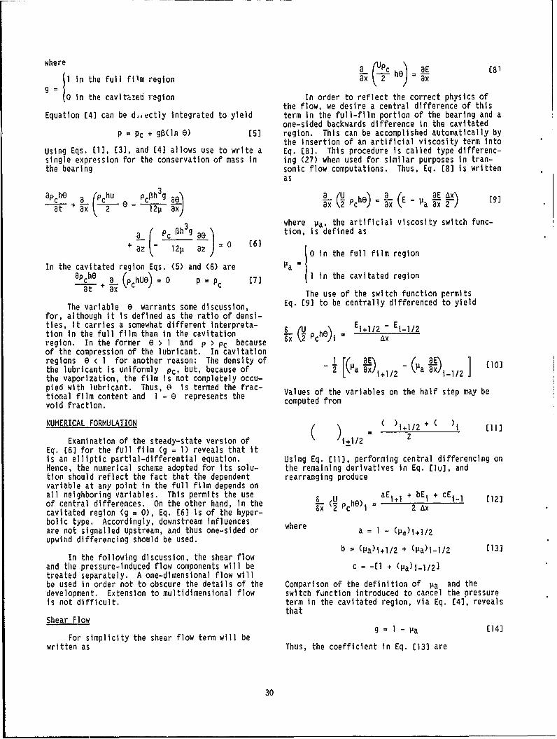
where a C8
I in the full film region cx 2 h ax
in the cavita-es region In order to reflect the correct physics ofthe flow, we desire a central difference of this
Equation [4] can be d,,ectly integrated to yield term In the full-film portion of the bearing and aone-sided backwards difference in the cavitated
P = Pc + g(ln e) (5] region. This can be accomplished automatically bythe insertion of an artificial viscosity term into
Using Eqs. (1], (3], and (4] allows use to write a Eq. [8]. This procedure is called type differenc-single expression for the conservation of mass in Ing (27) when used for similar purposes In tran-the bearing sonic flow computations. Thus, Eq. [8) Is written
as
apc he _a (PC hu PCI~h3g L q h). E-Pa' 9at ax 1211 ) (9
where Ia, the artificial viscosity switch func-
a_( L c 3hg ae 0 6 tion, is defined as
+ z 12I1 8z 0=0 (6] (0 in the full film region
In the cavitated region Eqs. (5) and (6) are Ia =
apche 3_ (PchUe) = 0 p = pc C7 1 in the cavitated region
at + x The use of the switch function permits
The variable e warrants some discussion, Eq. (9] to be centrally differenced to yield
for, although it Is defined as the ratio of densi-ties, it carries a somewhat different interpreta- , Ei+ II2 -Ei_/2tion in the full film than in the cavitation phe-region. In the former e > 1 and p > Pc because k- ci Axof the compression of the lubricant. In cavitationregions e < 1 for another reason: The density of a1 ( E) _(aE) 1 (10]the lubricant is uniformly Pc, but, because of 2 a ax)l 2 T1 a 1]2the vaporization, the film is not completely occu-pied with lubricant. Thus, e is termed the frac- Vausothvribeonhealsepmye
tional film content and I - e represents the Values of the varables on the half step may be
void fraction. computed from
NUMERICAL FORMULATION (( )1+I/2+ )I
Examination of the steady-state version of ±1+1/2 2
Eq. [6] for the full film (g = 1) reveals that itis an elliptic partial-differential equation. Using Eq. [11], performing central differencing onHence, the numerical scheme adopted for its solu- the remaining derivatives in Eq. (lu], andtion should reflect the fact that the dependent rearranging producevariable at any point in the full film depends onall neighboring variables. This permits the use U aE+ + bEi + cEi1-1 12]of central differences. On the other hand, in the T- 2 he) - -
cavitated region (g = 0), Eq. (6] is of the hyper- Sx I 2 Axbolic type. Accordingly, downstream influences whereare not signalled upstream, and thus one-sided or a = 1 -(a)i+12upwind differencing should be used.
b = Pa~ili/2 + (Pa~i-i/2 (13]In the following discussion,
the shear flow
and the pressure-induced flow components will be c = -(I + (1a1i-1/2]
treated separately. A one-dimensional flow willbe used in order not to obscure the details of the Comparison of the definition of Pa and thedevelopment. Extension to multidimensional flow switch function introduced to cancel the pressureis not difficult. term in the cavitated region, via Eq. [4), reveals
thatShear Flow
g = I -Pa (14)For simplicity the shear flow term will be
written as Thus, the coefficient in Eq. [13] are
30

a -(gil + gi)2} [21]
b = 2 - (gi+l +2gi + g(l )/2 (15] This term exists in the full film region (0 > 1),
but vanishes in cavitated regions (e < 1). Theswitch function g adequately removes the term
c - -[2 - (gi + gi-1 )/2]i and, therefore, no artificial viscosity term need
Now, if all grid points are within the full film be added for this purpose. Also, when this termall, l gin ponts are unity;theeforea 1e ul f, n exists, the governing equation is elliptic andal g's are unity; therefore, a Hn, e, and thus can be centrally differenced.c = -1. Hence,
Equation (21] can be treated in a variety ofe) Ei-1 ways which will ensure that It is central differ-
-( Pch) E i enced in the full-film and made to vanish In thex C 2 Ax cavitated regions. However, depending on the man-ner in which the switch function is handled and
PcU r(he) l- (he) [161 the particular differencing scheme adopted, theI +1 results vary significantly at the cavitation bound-
2Ax aries. Several alternative versions to the abovewere examined. The version that provided the mostwhich is the desired central difference form. On adequate and consistent results is one in which
the other hand, if all grid points are within the the derivative of g is not explicitly differ-cavitated region, all g's vanish so that a = O, enced. In particular, we may write thatb = 2 and c = -2. Hence,
ae 3() - I) ag(6 -1) 22]Ei- Eil_ PcUr(he)i - (h)g--=g = ax - ax
x2pchO)i = Ax =2-L Ax IThe last term on the right hand side vanishes
(17] for all values of E because the spatial deriva-tive of g vanishes for all e except at e 1;
and the desired upwind difference version is however, at this point, obviously, 6 - I isobtained, zero. Hence, we have
8e g( - 1) [23)The foregoing may be contrasted to Elrod's (15) ax- xshear flow expression, which is written as
u Now inserting Eq. (23] into Eq. [21) and centralu pche = _ Lh+l(l - gi_l)6 1_l differencing yields
Tx 12i g(e) = -x 12)1 x l)gi--1 t i- hi(1 - g1)ei + 2 (2 - g1)
-[hi+l+1 (+gthi( gi+lht+l gtl 12 p Ax2 /9+l"~
+ 2(gi-I - 2 + gi+l) - 2 (18]
If all grid points are within the full film, this /112 + h -1 2)gi(6i
yields
S c) = 19] 1/2 g)
which Is the same pressure term expression used bywhich, curiously, does not account for compressi- Elrod (15).bility effects. In the cavitation region,Eq. (18) produces 1SOLUTION PROCEDURE
6,'U ~ ~ 00) (he)1xx Y Pch I = Ax In this study cavitation in both slider and
journal bearings was examined. All sliders werewhich agrees with Eq. [17]. assumed to be one dimensional, whereas both finite
and infinite length journal bearings were consid-Pressure Induced Flow ered. Because the procedures for solving one- and
two- dimensional problems in these configurationsThe pressure induced flow, written in terms differed, details of each will be briefly described
of e is in the following sections.
31

One-Dimensional Problems be directly used in the solution. Brewe (7) hasused the Gauss-Jordan procedure for tHs purpose,
A purely implicit finite-difference scheme but found it to be extremely slow. To circumventwas used to numerically determine the distribution this problem, the two off-diagonal terms wereof e for all one-dimensional problems. By this lagged during the computations. By this proceduremethod, the finite difference version of Eq. (6), the following replacements were made:which incorporates Eqs. (12], [15], and [24), canbe written at each node in a general form as
an+ - 1 n ]al eI + bei E + ci e+ I = d1 (25] - n[28]
-c -1 e n+l n1T cT I e1
where the coefficients ai, bi , ci, and di are
functions of ax, At, 0, p, h, g, and the form of Thus, the terms were evaluated one time step bethe boundary conditions applied. Consequently, hind the actual computations and, therefore, arethe coefficients vary throughout the grid and known during the (n+1) st time step. Accordingly,change with time. Initially, all nodes are as- they were incorporated into the right hand side of
sumed to be in the full film, and at all nonboun- ey were ind the rithm ide
dary nodes e = I and g = 1. The switch function Eq. (27], and the Thomas algorithm applied.distribution was updated after every time step. The time march process was continued until
the change in ei between two time intervals wasBoundary conditions for slider bearings were less than 10-4. At this point, it was assumedtaken to be of the Dirichlet type in which e was that a converged steady state had been reached.set either greater than one (flooded) or less thanone (starved) on the boundary nodes. Because the Two-Dimensional Problemsinlet and exit values of e were specified, theentire collection of nodal equations could be An alternating direction implicit (ADI)arranged into the following tridiagonal matrix finite difference scheme (7) was used to determineform: the distribution of e for all finite journal
bearing problems. By this method, the time stepb I cI 0 n+1 d - a1e0 is split into two parts: in the first half,a b2 e+l d changes in the flow or x direction are calculated2 b2 2 n d2 while old e values are used to determine the gra-2 dients in the axial or z direction; in the second
S\ \•half, the recently calculated 0 distribution isused to evaluate the 'Flow direction gradients
0 a b e n+1 d c while the axial changes are updated.0 I-1 hi-1 .I-1. I 1 -C -e -
The Thomas algorithm can be used in each part[25] of the time step, if again, the appropriate varia-bles are lagged for the submerged journal bearingsIn thls form the collection of equations may be case. In accordance with Brewe's (7) suggestion,
readily solved by application of the Thomas the switch function was updated after every halfalgorithm (27). time step. Calculations were performed over half
the length of bearing due to symmetry with resepctFor journal bearings the boundary conditions to the axial center.depend on the means of lubricant supply. At oilgrooves, values of e are assumed which corre- On occasion an oscillation of the G distri-spond to the given supply pressure and are calcula- bution was encountered. This oscillation was trig-ted from Eq. (5]. The procedure remains the same gered at the cavitation node and has been reportedas for slider bearings. If, however, the bearing elsewhere (e.g., (7)). To remedy this problem, ais submerged, periodic or continuous boundary con- variable time step was implemented according toditions must be employed. Application of these the following scheme:conditions produce the following matrix form ofnodal equations
nt At ma)(k-l)/N-l)a n+1 (i mi k =1 2,..., Nb1 c1 1 tmma 0 r e ir d A9ta2 c2 12 =d2 [271 (29]
1:1 hereAtmin adAtmax are grid dependent andnil' N is normally taken to be 8.cI- 1 0 ai I- bi_ J e lI _1
Not only did the variable time step helpreduce the oscillation, it also reduced by approxi-
The coefficient matrix in Eq. (27] is not tri- mately 15 percent the number of time steps re-diagonal and therefore tha Thomas algorithm cannot quired for the solution to reach steady state.
32

Reference 28 examines the details of the cur- P - Pc + R(G - 1) [30]rent approach for both slider and journal bearingsin one and two dimensions. The principal purpose CONCLUSIONSof that effort was to compare the computed resultswith the published values of Elrod (14,15): The A cavitation algorithm that automaticallytwo algotithms produced comparable results. A sec- alters the form of finite differencing used forond purpose of that work was to examine a few modi- the shear induced flow has been developed. Thefications to the basic flow terms used in the Elrod algorithm is an outgrowth of the Elrod cavitationalgorithm. In particular, Elrod neglects in the algorithm. The two algorithms produce comparableshear flow term the compressibility effects in the results (28). However, the newer version may lendfull film region. Also, an approximate equation itself more readily to improvement. The effectsrelating the pressure to the fractional film con- of film compressibility, equation of state of thetent is sometimes used. This approximate relation lubricant, and grid spacing near cavitation bounda-uses the first two terms of a series expansion of ries on the pressure distribution were investi-the logarithmic term in Eq. [5], i.e., gated (28).
33

FUNDAMENTAL ISSUES CONCERNING THE MOVING BOUNDARY
CODA H.T. PAN 2 AND JEAN FRENE3
This discussion deals with the motion of an SOME EXPERIMENTAL FACTSinternal cavitation boundary of an incompletefilm, with emphasis on applications in which the Before attempting to examine the equivalentdynamic load component overshadows the magnitude Rankine-Hugoniot problem at the internal bounaaryof the static load. In such applications one is of an incomplete film, it is instructive to recallconcerned with supplying lubricant to the region some representative experimental facts of incom-where the surfaces are approaching each other, plete films. Two photographs (Fig. 1) which firstwhile voids should dominate the region of separat- appeared in the first Leeds-Lyon symposium (29),Ing surfaces such that viscous friction may be reveal that the notion of a smooth internal bound-kept minimal. The commonly accepted model of the ary which separates a filled gap from a void re-ir film is an attempt to approximate the extent of gion is at best an approximation. In reality, thefilling of the bearing gap. As engineers desire void region has a textured two-phase flow struc-to refine the design art, a more precise descrip- ture. The border between the filled gap and ation of the internal boundary of an incomplete void region exhibits irregularities associatedfilm in a bearing gap is sought. with the two-phase flow structure. To circumvent
such complicated details, it is convenient tc dealTHE MODELING VIEWPOINT with spatially averaged quantities of the two-phase
region in modeling.A predominant concern in the analysis of an
incomplete film is related to how flow continuity It is clearly revealed that a portion of theis maintained across the entire perimeter of the void-dominated region is locally filled with liquidfilm, which comprises: bridging both surfaces. Less visually evident, but
not to be overlooked, are the possibilities that a1. Inlet film edge or edges. thin liquid layer may be attached to either but
not both surfaces. Thus, a complete morphological2. Boundaries fixed by the geometry of the description of the void dominated region must in-
bearing. clude the following distinct liquid states:
3. Internal boundary or boundries. State A - A thin layer of liquid that adheresto the sliding (journal) surface.
Suppose, that at any instant, such delinea-tion of the film perimeter can be asserted. Then State B - A liquid streak or spot thatone can assign the value of the film pressure at bridges both surfaces.the film inlet to be that of the lubricant supplypressure; the geometrical boundaries can be repre- State C - A thin layer of liquid that clingssented by the ambient pressure; and the "cavity" to the stationary surface.pressure can be assumed to prevail near the inter-nal boundary or boundries. Consistent with this Excluded from present consideration are minute liq-set of pressure boundary conditions, a Dirichlet uid droplets that move freely between the two sur-type problem is prescribed by the lubrication faces.theory and may be completely solved to yield, notonly the film pressure distribution, but also thenormal film flux at all points of the filmperimeter.
While the film continuity condition is inher-ent in the interior of the bearing film as dic-tated by the lubrication theory, the transboundarycontinuity condition is more subtle. One may bor-row from gas dynamics the notion of the Rankine-Hugoniot conditions to allow for abrupt changes ofstate properties while preserving continuity oflubricant transport. As Rankine-Hugoniot jumpsare approximations of the diffused transport proc-esses across a moving shock wave, the analogy for i_a moving cavitation boundary is the change of flowstructure that takes place within a distance ofthe scale of the bearing gap.
Fig. 1. - Appearance of high void content flow2Digital Equipment Corp., Shrewsbury, MA. structures (29). (a) Divergent gap between3Professor, University of Poitiers, 86022 rotating cylinder near stationary plane. (b) Sep-
Poiters Cedex, France. aration of sphere from submerged stationary plane.
34

EQUIVALENT RANKINE-HUGONIOT This Is the equivalent Rankine-Hugoniot condi-'-ion. It shows that the sweeping speed of the
The equivalent Rankine-Hugoniot is concerned internal boundary depends on the neighboring filmwith the abrupt changes across a moving internal flux and the adjacent morphological states. A6oundary. It deals with the conservation of the more restrictive form of this equation wasliquid phase as related to the thin-film flow on originally presented by Oisson (8).one side, liquid-phase transport on the otherside, and the motion of the boundary.
IMPLICATIONS OF THE EQUIVALENT RANKINE-HUGONIOIFigure 2 shows that the normal unit vector of CONDITION
the Internal boundary at E is directed Into thevoid region and is inclined frcm the sliding vec- Equation (36] applies to both the breakuptor by angle a. The film flux, according to the boundary, where cos aL > 0, and to the reformationlubrication theory, is boundary, where cos a < 0. It must be satisfied
4, -(12ptY'h 3grad p, + 1/2 Uh (31] by all valid solutions of Incomplete films.
One of the solutionc of the Olsson-Rankine-In the void dominated region liquid content is Hugoniot condition is the bredkup line of a sta-given by the volumetric fraction or the fill fac- tionary, incomplece film. This corresponds to thetor for each of the three morphological states; Stationary breakup point:namely, eA, e)B, . The velocity of the intiernalboundary is orthogonal to itself. Therefore, the grad p = 0 M3al"sweeping flux vector" is
Q - Vh(l - WeA +I OR +ec)) (32] e + 1/2 eB 1/2 (37b]
The first of these is well known, but the secondThe transvoid liquid trdnsport flux is one Is rarely cited.
=Uh (WA + 1/2 C-6) (33] Another solution of the stationary Incompletefilm refers to a point on the reformation line or
Conservation of the liqii" phase requIre3 Stationary reformation point:
(4 - -. 0- (12p)-lh[((Cosa)(8P/8x) + (sin .) (8pfaz)1
Substituting Eqs. (31) t, [311 in, Eq. r341, ){/ -(A 4 1? e)} = 0 (8
-(02p) - h 2((cos a)(3p18X) 4 ,.sin 0.J0p/az)] This relation was used by Jekobsson and Floberg(1) to find the shape of at, enclosed cavity or a
+ U(cos a)[]/? - (E)A + 1/2 e8)B subme;rged journal bearing.
For a moving Internal boL'ndary, the Olsson-- V(l - (e A + OB+60 0 [35] RanrIne-llugoniot condition serves as a link be-
tween an elliptic field of the fully ftiled domainRearranqing, one finds an a hyperbolic field of liquid phase transport.
In this context one may observe that, because thenormal flux Is a onique consequence of the Dirich-
Vl - W +AE) + E, I UCos ac - (eA 1B let problem, one cen not rule out the possibili-A B R2- A e Bties that it may be inwardly directed, and t'nat
1l rl 2(csaa i (36] falm pressure may be less than the boundary
in order to use the Olsson-Rankine-Hugoniot- cronc tc.the three morphological state parame-
-n 'te CA, ail, andi ec mu .t be g Iven. The e)C~ probatly -,, be neglected unless there are special
J. c ca' d.dst for a bia-ed affinity of the lubri-E can'. to the stationa.-v bo.ar''1. surface. Anothe,
z p.*uzijk hypothesis is to Impose Gq. (37bi attz th bveiup p.,Iot, irrespective of whether the
'riteti-nal ro;nva , oay be in motion. Ong is thuslo . wlthi the remdinlne question of ow liquid
* --~X transzo.rt beyond thie nigniscus may ta, dividedbettleen .P.n adI.,ered film J- A and ;.rreamers Or,
Fig. ~.-Vector diagr~.m. S',.s ,tiat they are gi'or Initial values ait
35

point E; then subsequent liquid-phase transport Clearly, a physically permissible initial morpho-due to sliding can be stated as logical condition at E is in the range
(a/at)[(GA - eB)hJ + U(a/ax)[(A + 1/2 eB)hJ - 0 0 * ((A)E 9 1/2 [40)
[39]If one wishes to improve the speculative aspects
And, if one is willng to neglect "cross flowing" of these ideas, details of the three-dimensional,between the two constituents, the streamer trans- viscous, free surface flow with a moving surfaceport is given by and a moving attachment line must be studied.
The implementation of the Olsson-Rankine-(alat)(eBh) + 1/2 U(a/ax)(eBh) = 0 (39a] Hugoniot condition in a numerical computation
scheme is not trivial. It refers to the film fluxand the adhered film transport is given by at the boundary, which in turn shifts with time.
It is quite clear that the computation scheme must(a/Ot)(eAh) + U (Wax) (eAh) = 0 [39b] be capable of dealing with oblique mesh lines.
36

GEOMETRY AND MOTION OF THE MENISCUS
JEAN FRENE,1 LUC LAUNAY,1 AND CODA H.T. PAN 5
Dynamic loading is the primary concern in the Olsson-Rankine-Hugoniot condition is to be satis-design for journal bearings of automotive engines, fled. A centrally fed short journal bearing willOil supply is to be optimized to ensure that the serve as the specific model in the present work.minimum gap is adequate while friction is to be The dimensionless film thickness of a dynamicallykept as low as possible. Operation with an incom- loaded journal bearing, neglecting angular mis-plete film is typical in such bearings, alignment, is
In the past the v-film model is commonly H I + c cos(e - ) 141]used in analytical studies. As engineers strivefor more accurate modeling tools, a more precisetreatment of the dynamics of the inccmplete film In Eq. (41) both c and *, may be time-dependent.is in order. The if-film model, as applied to the employing the short bearing approximation ofsteady-state, plain journal bearing, is equivalent Ocvirk, the Poiseuille component of the circumfer-to the GUmbel approximation in rejecting the subam- ential flux is neglected; thus,Went portion of the pressure field. In conjunc-tion with the short bearing approximation, the (42]if-film model yields simple, closed-form analytical 1/2 WRCHresults for both static (eccentricity) and dynamic yz = -(12p)-1 (CH)3(8p/az) (43](radial velocity) effects. This combination ofanalytical tools has been the backbone for thestudy ol journal bearings in automotive engines. The continuity condition, with allowance for mo-The Reynolds-Swift-Stieber cavitation model (RSS) ton of the journal, ishas been regarded to be more precise. Because itrequires a null condition of the pressure gradient (8%/86) + R10yz/8Z) + RC(SH/at) = 0 (44]at the cavitation boundary, it had been thought tobe intrinsically contradictory to the short bear-ing approximation and had been used primarily in Upon making use of Eqs. 141] and (42], one finds"FDM type" numerical computations. More recently,a modified Reynolds-Swift-Stieber model was uo.d .2 -2- cto improve the short bearing approximation. Cavi- (82P/8z) C(2uC)H cos e -ties of both vented and enclosed types have beensuccessfully modeled. 1 - l
The Reynolds-Swift-Stieber model, which is - - sin [45]restricted to the steady-state condition only, isthus, valid for either a static load or a rotatingload. As it was applied with the short bearing Boundary conditions for the chosen problem are ofapproximation, the results are appropriate for the Dirichlet type. At the lubricant supply planestatid-load considerations of the journal bearingor for high rotating loads of the squeeze-film p(z = 0,e) = Ps [46]damper. The bearings of the automotive engineexperience oscillatory loads which are not of the and at the end of the filmpure rotating type, and the static load componentis not totally negligible. These applications p(ze,e) = 0 (47]motivate us to consider the more complicated prob-lem of a truly time-dependent incomplete film. The end of the film may be at either the dischargeThe short bearing approximation was retained for end of the bearing or at the internal boundary ofthis work, so that one may direct full attention the incomplete film; i.e.,to issues related to the moving cavitationboundary.
Ze 9 L/2 (48]ANALYTICAL APPROACH
The elliptic problem can thus be determined byThe time-dependent, incomplete film problem integrating Eq. [45] with the constants of integra-
requires the simultaneous treatment of an ellipti- tion chosen to satisfy Eqs. (46] and (47], to yieldcal domain and a hyperbolic domain, which arejoined at the moving internal boundary where the p(z,e) ps (I -2z/L)
4Professor, University of Poiters, 86022 - 1/2 z(L/2 - z)(2,I/C2 )H"3 ( cos(e -Poitiers Cedx, France.
5Digital Equipment Corp., Shrewsbury, MA. - (1/2 w - *) sin(6 - ) (49]
37

LIQUID TRANSPORT IN THE DISCHARGE CAVITY But in the reformation branch fA is computedaccording to Eq. (51], so that Eq. [52] would be
In the discharge cavity liquid phase is used In its fuli form. It is convenient to repre-assumed to be In the state of an adhered film. sent the sweeping motion byThe liquid content is given by the adhered-filmfill factor fA. Transportation of the adhered /a csfilm is described by the equation atze csc V
+ HA 0 [50] .(1 - fA)-'[1/2 U (1 - 2fA) ctn
where HA - fAH. The time-stepped representationof this solution is - (CH)2(12p)- (ct. . sin +z 58]
HA(e,z;t) = HA(e - WAt, z; t - At) Then updating of the boundary geometry can be
exe^,jted by computing= 1/2 H(E - wt + wc, z; -) (51] t
for t > T, where t is the instant the adhered Ze (9,t) = Ze (e, t - At) + (a/at)ze dt (59]film was formed at the breakup point. et-At
MOTION OF THE INTERNAL BOUNDARYat all inner points of the Internal boundary The
The condition of Olsson-Rankine-Hugoniot end points move along z = L/2 and can be calcula-gives the sweeping speed at an internal boundary ted fromto be (a/at)x e = sec V
z=L/2z=L/2
V = ( .. fA)- 1/2 U(l - 2fAY cos (1 - 1 1/2 Ul -
(CHI 2 (12p lcos (-A - + sin a/2) (52)2 1 ( -Th swepn spee VZ (CH 2 \ aep)I 8 tan az o =/
The sweeping speed V is aimed along the cavity,
pointing normal to the periphery. The boundary at (60]any instant is described by
Again, fA would be set to 1/2 for the breakupZe(e,t) L/2 C53] point but would be computed according to Eq. (50]
which has a waist at Gw such that from the prior history of the reformation point.
(la/e)zelew = 0 [54] EQUATION OF MOTION
The journal mass may experience an accelera-The inclination of the periphery normal is tion as the bearing film force may not cancel the
applied force completely. This acceleration cantan-I(a._ - /2 55] be integrated in time to determine the varying
6= velocity of the journal center. The correspondingsqueeze-film terms would necessitate recalculation
Branches on either side of the waist are of the fluid film forces with the new cavityjoined with null slope. But analytic continuation boundary.from one to the other across the waist point cannot be assured because computation of Eq. (51]would follow different rules for the two branches. PERIODICITYIn the breakup (e < ew), the Reynolds-Swift- In the automotive application the periodicStieber law applies so that state of the constant speed operaton of the
= I12 (56) engine is of interest. The character of the aboveprocedure of calculation does not assure this per!-odicity in advance. Therefore, it is necessary to
and perform the computation for more than a fullcycle, until the results demonstrate complete
V (ea)u2 -(6p) 'cos s .in c_ (571 attenuation of the Initial transient caused by theRbreakup 6 ae azi assumed initial values of c and 4.
38

CLASSIC CAVITATION MODELS FOR FINITE ELEMENT ANALYSIS
J.F. BOOKERE
A review of several mathematical models com- ently cavitating) region is characterized by nullmonly used to incorporate cavitation in the finite- pressure and negative density time rate of change.element analysis of lubrication is presented. The The physical interpretation is obviously that ofvarious mathematical models are completely equiva- vaporization. It can be shown that the three view-lent in the limit, but they differ in physical points are equivalent in the limit. Any one isinterpretation and numerical implementation. The sufficient in principle to fix the (instantaneous)models are classic in the sense that they are no.t division of complete and Incomplete film regionsflow preserving. For clarity we review the devel-. and/or the positions of their (free) boundaries.opment of finite-element lubrication analysis both In practice, however, all three viewpoints intro-with and without the complication of cavitation. duce nonlinear complexities to the problem and a
consequent layer of iteration to its numericalCAVITATION EXCLUDED solution.
Transient lubrication analysis is usually Focusing on boundary location, as in thebased on a boundary-value problem in which the first view, is particularly awkward for finite-pressure satisfies the Reynolds differential equa- element analysis. Since locations of free bounda-tion (30) over a coriplete film region, and either ries are unknown a priori, they must be selected inpressure value or normal pressure gradient, respec- iterative trials (with attendant nodal discretiza-tively, satisfy "essential ard natural" conditions tion) followed by solution of a well-posed problemeverywhere on its boundary, whose location is fixed over the complete film region (with only one ofin the absence of cavitation. In an equivalent the two Reynolds boundary conditions fixed and thevariational (extremum) problem (31), a pressure other evaluated for iterative closure).distribution is sought which minimizes a func-tional (integral) involving variants of the Rey- Focusing on local behavior is particularlynolds operators over the region and "essential" convenient for finite-element analysis, since itboundary conditions on its boundary. allows a fixed nodal discretization. The con-
strained quadratic programming problem of the sec-Following finite-elemen. discretization of ond view can be solved in a number of ways, all
the pressure field, the functional can be expressed iterative. Physically appealing is Christopher-in terms of nodal pressurc values. Necessary con- son's method, in which the linear equation set isditions for the resulting unconstrained minimiza- solved by Gauss-Seidel (or SOR) iteration, aftertion (quadratic programming) problem give a linear which any computed negative pressures are set toalgebraic equation set. The set can also be ob- zero, and the process repeated until satisfactorytaned through application of Galerkin's method to convergence is achieved. (One can imagine anthe boundary value problem. analogous physical process in which quantities of
liquid are converted to vapor.) The scheme hasSolution of the linear equation set com- been used with success (32,33); its main drawback
monly accomplished by either direct decomposition is its reliance on the iterative convergence of(e.g., Gauss, Choleski, LUD (lower and upper real variables. An alternative to the constraineddecomposition)) or indirect iteration (e.g., quadratic programming problem is the linear comple-Gauss-Seidel, and SOR) methods. mentarily problem (equlivalent in the limit). Its
numerical application (34-36) appears identical toCAVITATION INCLUDED that of the mixture law (37), in which one seeks
to partition nodes as cavitating (or not), depend-In the classical view of transient cavitation ing on whether particular equality and Inequality
analysis, the complete film region has one or more constraints are satisfied.free boundaries on which both pressure value andnormal pressure gradient satisfy so-called Rey- A metaphor would be a "porcupine bearing" innolds boundary conditions (usually null). In a which all interior nodes communicate via feed/bleedsecond view, a nonnegative solution (over the en- check-valves to an ambient pressure source. Al-tire film region) is sought for the variational though no cavitation at all would occur in such aproblem. The resulting constra ied minimization preposterous arrangement, the mathematical problem(quadratic programming) problem no longer admits a is identical to those above.simple linear algebraic solutlo,. Third, we canchoose to apply a mixture law view of two-phase Solution of all such problems is a matter of(caviltating) fluids (15). Applied here, a com- Integer programming (guesswork) combined with di-plete film region is characterized by positive rect solution of linear equation sets for pres-pressure arid constant (mixture) density value sures and direct evaluation for flow terms. In(unity volume fraction); an incomplete (incipi- Murty's method (analogous to Christopherson's
method) nodes at which constraint violations occurare shifted to the opposite partition for the next
BSchool of Mechanical and Aerospace Engineer- iteration. The great advantage of such integering, Cornell University, Ithaca, NY. iteration is that convergence is abrupt and unam-
39

biguous; with a bit of luck, it is also fast. Fig-ure 3 shows pressure distributions from a seriesof such steps, starting with the assumption of nocavitated nodes whatsoever. It should be notedthat such a blind start is unnecessary in practice;reasonable first iterates result in convergence inone or two steps. (Corresponding nodal flow quan-tities do not provide for a meaningful plot inthis previously unpublished study by LaBouff.)
SUMMARY
Several mathematical models commonly used toincorporate cavitation in the finite-element analy-sis of lubrication and suggested both physical in-terpretation and numerical implementation. Theseclassic models, which are equivalent in the limitof discretization, describe incipient (quasis-tatic),nonevolving (flow-preserving) transient cav-itation, in the sense that vapor only begns toform before the liquid is replenlshed. Thoughthey are physically unrealistic in a really mostbasic way, the fact that they fix the cavitationsituation quasistatically in instantaneousresponse to bearing kinematics means that the de-
grees of freedom of the problem are hundreds oftimes fewer than if nodal density (volume frac-tion) must be called on to reflect evolutionaryhistory. The models thus lead to computationallyefficient algorithms and are, therefore, likely topersist for a long time to come, whatever their de-partures from realism.
Fig. 3 . - Convergence of a pressure profilewith Integer iteration.
40

MATHEMATICAL MODELS AND RELATED ALGORITHMS IN CAVITATION PROBLEMS
G. BAYADA,7 M. CHAMBAT,d M. EL ALAOUI9
We concern ourselves with gaseous cavitation 1. For a Journal bearing with an axial supplyoperating under both the steady-state and transient line located in the convergent part of the gap, aconditions. Applications to circumferentially sup- strange pressure distribution has been obtainedplied bearings and to seals are given. We describe numerically with nonconnected active areas (44).first the widely used cavitation algorithms and therelated mathematical problems especially in view of 2. The balance between the input flow and out-the output flow computation. We propose new algo- put flow is not always satisfied, especially forrithms using the finite elements variational ap- seals (45).proach whose reliability has been theoreticallyproved. For unsteady problems, a time discretiza- Theoretical studies lead to the following conclu-tion procedure using the characteristic lines sions (46):allows us to introduce a set of stationary likeproblems for which equality between input and out- - Formulations c, d, e, f are equivalent. Theyput flows is preserved. are associated with a well-posed problem
which has a unique solution that fulfills theSTEADY STATE PROBLEMS conditions of Eq. (61]. This solution is
such that the cavitation area is locatedClassical Models only in the divergent parv of the mechanism.
The GUmbel (or Half-Sommerfeld) model of A New Modelcavitation is widely used because it is easy toimplement, but it is associated to a false boune. Various interpretations of the model areary condition on the free boundary surface. The described in references (1) and (14). A summarysituation is much more confusing for the Swift- of those interpretations is given here. The pres-Stieber or Reynolds modcls. The validity of this sure is not a unique parameter governing the cavi-last model has been supported in various ways: tation phenomenon; and we must introduce another
parameter e which can be viewed as a saturationa. The regularity condition is required to function or a fractional film content (the percent-
hold at the free rupture boundary (38): age of oil contained in an elemerntary volume) orthe result of the homogenization of the oil fin-
p = 8p/an = 0 (61] gers. In any case, the cavitated area is notempty as it contains some lubricant.
b. In numerous papers condition [61] is gener- The flow is now defined byalized to any free boundary (39).
* = h3/(12p)Vp - eU h12 (62]c. In a more mathematical formulation, condi-
tion (61) is deduced from a minimization argument assuming (p 0 and 0 < E < 1), with the con-(40): Through all positive smooth functions satis- straint that (e = I if p > 0) then the conditionfying the external boundary conditions, the pres- div ( ) = 0, in a weak variational sense, givessure is the function that minimizes the energy the equations for the problem.integral.
Numerical Method and Applicationsd. The pressure is the solution of a varia-
tional inequality (41,42). Elrod proposed an iterative procedure (15)well adapted for finite difference discretization.
e. The pressure is the solution of a comple- We propose a new procedure using the finite-elementmentary problem (43). discretization, whose accuracy and convergence have
been rigorously proved (46).f. The pressure is obtained by the Christoph-
erson procedure. It is possible to express the problem in terms ofone single unknown X which is a solution of a
There are two types of unpleasant problems nonlinear equationthat appear both analytically or numerically:
X = B(X) [63]
This equation can be solved using the fixed-point7Centre Math 403, INSA 69621 Villeurbanne, method starting from zero. Ince X is known, it
Cedex, France. is easy to recover the initial functions p and'Lan Math, University of Lyon 1, 69622 e.
Villeurbanne, Cedex, France.9University of Caddi Ayyad Fac Sciences, Me consider a bearing with a circumferential
Marrakech, Morocco. supply line. We compute the load, the attitude
41

angle, and the input/output flow rates for various (h) _.h3 1 1 1(8hU) = 0 [64]supply pressures, various eccentricities, and at a-- T ax) + 2 ax C
three length to diameter ratios. The first compu-tation is related to the Reynolds model solvedusing the Christopherson numerical procedure, and This equation includes all the above equations,the second one to the Elrod-Jacobson-Floberg model especially the condition on the free boundary,
using the new procedure. Both computations in- which appears exactly as the classical Rankine
volved finite elements. Results demonstrate lit- Hugoniot condition for shocks in hyperbolic equa-
tle discrepancy for the load between the two tions and is equivalent to those proposed by Elrod
models, but gave more discrepancy for the eccen- (14). Supplementary data involve (1) boundary
tricity angle. The equality between output flow conditions on the pressure and (2) initial data
and input flow is very well preserved for the sec- for e.
ond model. However, it is not true for the firstmodel for which the discrepancy increases with Numerical Procedure (47)
eccentricity and length to diameter ratio. The starting point is to substitute the total
TRANSIENT PROBLEMS derivative D(eh)/Dt for l/2[a(ehu)/ax] + (80h/at)with the meaning that the derivative in t is taken
Classical Models along the direction U so that the equationbecomes
The same analysis can be made for steady- D(eh) __J'h3 aD)-state problems from both the theoretical and Dt axlIT ax =0 e = I if p > 0 (65]
numerical aspects. The Christopherson procedureis commonly used with an explicit or implicit timedescretization. Bad results are usually reported and then discretize the first term of the equation
for the balance of the flow, especially for in time along the characteristic line.
seals. These will be illustrated as a primeexample. CONCLUSIONS
tlew Model An application to a seal was made in (47).
Rectangular finite elements were used.
We describe it first in the particular caseof an infinitely long mechanism. However, the gen- I. The discrepancy between input mass floweralization to real two-dimensional geometry is and output mass flow never exceeds 4 percent instraightforward. each period.
As in the steady-state problem, a unique 2. Periodicity of the load and of the flowsequation in a weak or distributional sense is well is obtained in four periods. The cavity followssuited for numerical procedure: the rotor movement when x2 = 2xl.
42

NON-NEWTONIAN EFFECTS IN FILM CAVITATION
A.Z. SZERI'0, K.R. RAJAGOPAL10, AND ZHANG'0
There exist in engineering usage a vast As t varies, so will vary the position x ofnumber of fluids, both naturally occurring and man the particle X. We insist that this relationshipmade, the behavior of which cannot adequately be (Eq. [66]) be Invertible; i.e., that two particlesdescribed by classical, linearly viscous theory. do not at the same time occupy the same spatialThough such fluids also abound in tribological position, and write for the inverse of Eq. (66)practice, we have accumulated only scant knowledgeof the 9ffects non-Newtonian behavior might have X . x-l(xt) (67]on tribological performance. The principal prob-lem we are faced with in the area of non-Newtonian This is just mathematical shorthand for the state-fluid mechanics is our inability to successfully ment that spatial position x at time t iias themodel the stress-deformation relationship of a par-thcular materl. But, in part, we can also blamethe lack of reliable experimental data and, thus, 1.0 F
the absence of guidance to theoretical research. 0 0.10 .3
Viscoelastic fluids differ from Newtonian '0 .5fluids in one main aspect, viz., viscoelastic .8 .7fluids possess memory. Having memory, for the 0 .9fluid, means that the stress presently experiencedby a fluid particle is no longer determined by ex-isting conditions alone but depends on deformation .6history of the material in the neighborhood ofthat particle. The principal practical manifesta-tions of non-Newtonian behavior are normal stresseffects and shear thinning. We have recently .4noted another strong effect on the velocity pro-file in a thrust bearing-like geometry (48)(Fig. 4). Velocity profiles were measured usinglaser Doppler Anemometry, In a flow between rota- .2ting parallel disks. Figure 4 displays the tangen-tial velocity field at a fixed radial position,with the top disk stationary and the bottom diskrotated at constant angular velocity. The profilein (a) was obtained in water, and that in part (b) 0 .2 .4 .6 .8 1.0was measured in a viscoelastic fluid (0.029 per- v0/Ro Bcent polyacrylamide solution). It is easy to dis-cern the qualitative difference between the twoprofiles: Shear thinning occurs at a certain axi- 1.0al position, the separation distance of which fromthe bottom plate depends on various parameters, re- RAD/S RPMsulting in large velocity gradients. The cause Z 3.497 33.4for this localized action is not known to us. .8 L 0 3.905 37.3
0 4.712 45.0We have also noted recently (49-51) that jour-
nal bearings lubricated with non-Newtonian lubri-cants could be less susceptible to thermal effects .6when compared with bearings lubricated with Newto-nian fluids.
In this note we wish to further explore lubri- .4cation with viscoelastic fluids and focus our at-tention on cavitation, first wishing to place theconstitutive relationship of the class of fluidswe employ, in proper perspective. To this end we .2 0define the motion of a fluid particle as follows.Tf fluid partile X at time ' occupies the spa- (b)tial position x, we write
0 .1 .2 .3 .4x(X, t) t > 0 [66] ve/RoB
IODepartment of Mechanical Engineering, Uni- Fig. 4. - Azimuthal velocity between parallel,versity of Pittsburgh, Pittsburgh, PA. rotating disks. (a) Newtonian. (b) Viscoelastic
fluid.
43

fluid particle X as Its temporary resident. It has been shown that under certain condi-tions Eq. [71) has an expansion in terms of cer-
Consider now another time instant - < t, at tain differential quantities. When this expansionwhich tim, our fluid particle X was resident at is terminated at a low order and when account isthe position . Hence, we have made of the particular geometry common to most
lubricant films, we essentially obtain that the= x(X,E) (68) stress has the following structure (cf. (50))
But we can substitute for X From Eq. (67) into - )Eq. £68) and have T - - p1 + (11 + 1(tr A1 1 A [72)
X 1X-I(xt),t)1 -: xt(xt) (69] Here, p is the molecular viscosity, a and 13are non-Newtonian parameters, and Al and A2 are
The relationship = xt(x,t) states that the fluid the first and second Rivlin-Ericksen tensors,particle that is In position x at the present respectively, defined bytime t, was in position g at some former timeinstant we call -. If we now let -t 0 vary + +while calling t the present time and keeping it Al - (grad v) + (gradfixed, we are looking backwards In time and trac-Ing the history of motion of the fluid particle X. (73)
The vector valued function xt occurring in A2 = dA/dt + AI(grad v) + (grad V)TIEq. (68) is called the relative deformation func-tion. If the deformation xt described is smooth The material parameter promotes normal stressand the material has no microstructure (and this efe il ameter 0 pot s shea thinn
applies to most deformations and most materials in and a 0 w make tfli shear thicken.engineering practice), we can define the gradient and a > 0 will make the flu d shear thicken.of xt, called F(s), through (52). This is easily seen when Eq. [72] is written for
ol F simple shear flow, for then
d9 = F(s) dx; F(s) = @8/8x; s = t - ( (70])
Eqain(0 hw htthe gradient of xt, in Mdl xy = (1p + 13(du/dy) ](du/dy) (741Equation 70 shows thatModels of this type (Eq. (72)) h -e been used byour notation F(s), is indicative of how an Infini- several researchers (53-55). He have applied ittesimal line element dg at the instant of time to journal bearings (50,51) and demonstrated thatr had to be stretched and rotated so as to become even a slight departure from Newtonion behavior,the line element dx of the present time t. As as measured by the numerical values of a and 1,we let s > 0 increase, the equality here signi- renders bearing performance relatively insensitivefying present time, we have the history of deforma- to changes in lubricant temperature.tion characterized by F(s).
In a continuation of previous effort, weThe deformation gradient history F(s) is looked at non-Newtonian effects on cavitation in aused in the definition of a class of fluids called journal bearing. Figure 5 shows the slow, gradual"simple fluids". Simple fluids (and the adjective change in the pressure profile as the material"simple" refers to the lack of microstructure anddoes not imply that the fluid is elementary in anysense) are those in which the stress T at a 6point depends on the history of deformation of a 3.70neighborhood of that point, or 0.01
.03s = 2.96 . .02
T= f (F(s)) (71) "'- .01s=O .005
2.22 "" 0 (Y 0 .)There is a fairly good agreement among practition-ers of non-Newtonan fluid mechanics concerning 14the validity of Eq. [71) and the assumptions lead- 1.48ing up to it. But, there is disagreement on howto proceed further, for Eq. [70) is hardly apractically useful statement.
There are many ways to approximate the func-tional f in Eq.[71]. Integral representations 0 4 80 120 160 200 21i0 280 320 360are well received by the rheology community in gen- POSITION, DEGeral but have to be as yet handled numerically ina practical application. Differential representa- Fig. 5. - Pressure profiles in shear thickeningtions, on the other hand, yield to numerical treat fluid (y = -0.1).ment but allow only for infinitesimal memory.
44

3.70 3.70
2.96 4 ik 2.96
2.22 2.22
~ 1.48 rO0 1.481.,48 .01
,..- .02
74\ .74.04.01 (y= 0.01)
40 80 120 160 200 240 280 320 360 0 40 80 120 160 200 240 280 320 360POSITION, DEG POSITION, DEG
Fig. 6. - Pressure profiles in shear thinning FIg. 8. - Pressure profiles at y = -0.1.fluid (y = -0.1).
61
MS 5
ZZ 2
A A
Fig. 7. - Foldlines (S) on solution manifolds (M). 0 I-.040 -.024 -.008 .008 .024 .040
parameter is made progressively smaller whileis kept constant. To be precise, it is not m Fig. 9. - Pressure maxima at y -0.1.
and 3 that are used as the parameters of the prob-lem but their nondimensional counterparts y and6, defined by Our investigations are incomplete at this
LU = 68U2 stage, and conclusions are not well founded. Buty 2 (75] they suggest the presence of a fold line on the
PI PC2 solution manifold at 0.0025 < < 0.005 wheny -0.1. Here, the two solutions, one with cavi-
Here, U is the surface velocity of a shaft of tation and one without, join. Of course it is pos-radius R, and C is the radial clearance in the sible, or even likely, that the noncavitating solu-bearing. tion, if it at all exists, represents an unstable
branch and is therefore not reproducible in theFigure 5 shows pressure profiles for shear laboratory. All we suggest at this juncture is,
thickening fluid, S 0 , at y = -0.1. As the that there might be an other than the classical,value of S decreases from & = 0.004, the maxi- cavitating solution to the problem. Our next taskmum pressure, gradually decreases, otherwise the is to trace the fold line on the solution manifoldprofile seems to change little, using continuation methods. Figure 7 illustrates
Figure 6 shows pressure profiles again at some possible fold lines of an equilibrium surface.y -0.1 but, now, for a shear thinning fluid.Starting at S = -0.004, the pressure curve shows Figure 8 shows two pressure profiles, oneno cavitation. Increasing the value of slowly obtained with 0.0025 exhibiting noncavita-increases the maximum pressure, but, otherwise, tion; while the other, calculated with 1 - 0.005,the shape remains invariant, still showing no cavi- exhibiting a classical, cavitating profile.tation. This phenomenon persists up to the value Except for the presence or absence of cavitation,6 = 0.0025, a slightly shear thickening fluid. the profiles are virtually identical. Figure 9But at a somewhat larger value of 6 0.005, displays the pressure maxima at y = -0.1 as theFig. 5 already shows cavitation, parameter 3 is varied.
45

It is well known that nonlinear problems much more than idle mathematical curiosity. Thisoften yield a rich multiplicity of solutions, sup- of course, constitutes no proof that what we haveported on identical steady-state boundary condi- here in the non-Newtonian journal bearing is alsotions. As an example we may quote the work of multiplicity of solutions; but it perhaps suggestsBeJamin and Mullin (56), who found 21 solutions in that our findings should not be discarded out ofthe flow between short, concentric rotating cylin- hand.ders. Their work was experimental and thus shows
I
46

CAVITATION MODELING FOR ANALYSIS OF FLUID FILM JOURNAL BEARINGS
L.E. BARRETT'' AND L.A. BRANAGAN"'
A reasonable description of the cavitation plifying approximations to Reynolds equation arephenomenon in thin fluid films is critical to the used, such as the short bearing approximation. Itaccurate prediction of the pressure distribution, is called the half-Sommerfeld pressure boundaryand hence forces, in fluid-film journal bearings, condition.Cavitation occurs when the fluid film is subjectedto conditions of tension which tend to produce neg- For finite-length solutions, this approachative pressures within the film. Usually, under has usually been used to avoid an iterative solu-these circumstances, the pressure falls to essen- tion for the trailing boundary of cavitated regiontially the vapor pressure of the lubricant, but no where the pressure is the cavitation pressure andlower. Gaseous components of the lubricant come the pressure gradient is zero, thus ensuring massout of solution and, together with vaporized lubri- flow conservation. This is referred to as thecant, form a two-phase flow field of bubbles and Reynolds boundary condition. Actually, the trail-streamers. Cavitation usually occurs in regions ing cavitation boundary can be easily found with-of diverging film thickness within the bearing and out iteration by back solving for the pressure,depends on the supply pressure of the lubricant to starting from the trailing edge of the fluid filmthe bearing. Hence, cavitation regions can be and substituting the cavitation pressure wheneverdrastically altered by changes in bearing geometry the solution predicts a subcavitation pressure.and supply pressure, and for a given bearing they If coupled pressure-temperature solutions areare dependent on operating parameters such as being sought, the problem is already highly itera-shaft speed and bearing load. Figure 10 shows a tive, so there is no advantage to be gained bycomparison by Tonnesen of predicted and measured using the half-Sommerfeld cavitation boundary con-pressures obtained in a two-axial-groove journal dition, even if a forward substitution scheme isbearing. This figure clearly shows the cavitated employed.region of low pressure that occurs in the top padof the bearing in which a diverging film thickness Once the cavitation boundaries are known, theoccurs. It should be noted that cavitation within heat generation within the cavitated region mustbearing fluid films is not considered to be inher- be calculated. The heat generated has an indirectently bad. Only rarely has cavitation been cited effect on the cavitation boundaries and no effectas the primary cause of bearing damage or failure on the pressure within the cavitated region. Thedue to surface pitting, and cavitation control is effect on the boundaries comes about iecause therarely a goal of bearing design except in the case heat generation alters the temperature within theof squeeze-film bearings, fluid film in the cavitated region. Thus, the tem-
perature of the lubricant exiting the trailingThe fluid mechanics and chemistry of cavita- edge of the film is altered. In turn, it affects
tion Is very complex. Fortunately, for most the temperature of the film at the leading edge ofpractical design considerations, a detailed the following pad.description of the prenomenon is not required.Hhat is required is an accurate prediction of the The usual theoretical approach is to use whatcavitation region boundaries and the pressure, tem- is called hot oil carry over calculations. Inperature, and shear heat generation within the this method the lubricant exiting the trailingregion. This is usually accomplished by applyingreasonable auxiliary conditions on the fluid film 6 -pressures and temperatures obtained from a coupled PRESSURE AT THE BEARINGiterative solution of the governing equations, the CENTER PLANEReynolds equation for pressure, and the energy 5
equation for temperature. The solutions are depen- - PRESENT WORKdent on boundary conditions of supply pressure and 4 - LUND THEORYtemperatures and may include the heat conduction --- EXPERIMENTeffects in the bearing and shaft. The simplest so- 3 -lution is to solve the governing equations indepen- : TONNESEN BEARING
dent of the existence of cavitation and to set any 3500 RPMpredicted negative pressures to the cavitation 2 8600 Npressure using a forward solution for the pressure C.
starting at the leading edge of the film. It is Ieasily shown that this approach violates mass flowcontinuity, but it does provide a reasonable ap- o -------------------proach to defining the cavitation region for manybearing applications, particularly if certain sim- -1
0 60 120 180 24I0 300 360_
''Department of Merhanical and Aerospace Engi-neering, School of Engineering and Applied Sci- Fig. 10. - Predicted and measured pressures in aence, University of Virginia, Charlottesville, VA. two-axial-groove bearing.
47

75 - 172 - o AUEPRSN WR0Y 0 MEASUREDPRESENT WORK u3 162 A WITH mu(y)
70 . LUND THEORY mu(y)0 EXPERIMENT 15
~65 - 126o 0 00 1 132
S60 ~_j0 122
00 0 0 60 120 180 240 300 360
550 0 ANGLE FROM HORIZONTAL, DEG
<Fig. 13. - Predicted and measured temperatures in0a two axial groove bearing with two-phase flow
50 model used in cavitated region. Effect ofcross-film bearing; Tonnesen bearing; 3500 rpm;
iS I I I Babbitt temperature profile; 1289.5 lbf load; w/0 60 120 180 24I0 300 360 thermal cav.
0loped in the cavitated region. This model treats
Fg. 11. -Predictbedaing. eure presthe cavitated region as one with a central streamertwo-axial-groove bearing. Experpemnt of lubricant flowing along the bearing centerline.conditions: Tonnesen bearing; 3500 rpm; 5600 N; The heat generation is easily calculated since theTs = 50 °C. Present work used 20 elements and 30 velocity gradient across the film is essentiallyharmonics, constant, at least for laminar flow, being approxi-
mately RwI2, where R is the shaft radius and
_ _ _ _ _ _w is the shaft angular velocity.
GAS Calculations performed using this model are-FLUID shown In Fig. 11 for a two-axial-groove bearing.--_ _This figure shows the circumferential temperature
variation of the bearing surface in both the
TOP VIEW loaded pad and cevitated pad. Measured tempera-tures made by Tonr~esen are shown. Although heat
a CAVITAlION ONSET conduction into the shaft and bearing surface is_ included In the theoretical calculations, the
_ _ _analysis predicts significantly higher tempera--- FLUID ____ GAS tures in the cavitated region than those meas-
__________ured. This suggests that the heat generation777777 7 /77 model is predicting larger shear heating than
SIDE VIEW actually occurs.
Fig. 12. - Model for two-phase flow in cavitated Figure 12 shows a two-phase lubricant-gaslubricant films. model for heat transfer in the cavitated region in
which the lubricant adherence to the shaft surfaceedge of a pad Is assumed to cling to the shaft and can be assumed. Further, it is assumed that theto be carried into the inlet of the following height of the film diminishes along the divergingpad. If this volume of lubricant is insufficient portion of the gap rather than have the filmto fully supply the following pad, the remaining decrease in width. This model has been developedvolume is made up of lubricant supplied through by observations of flow fields In transparent bear-the inlet supply groove. The temperature of the ings, which suggest that this type of flow patterninlet lubricant is determined by the ratios of the exists. Because the viscosity of the gaseous por-carry over and the supply groove volumes at their tion of the film is considerably lower than thatrespective temperatures. of the lubricant, most of the shearing occurs in
the gaseous region. Thus, this model generatesA detailed theoretical model of the two-phase less shear heating in the cavitated region. The
flow in the cavitated region is usually not con- heat conduction to the shaft and bearing surfacesducted. Some assumption of the flow field is is also modified because of the difference intherefore made, and the shear heating of the iubri- thermal properties of the two fields.cant in this region is determined by supplementalcalculations. The simplest model is to assume Figure 13 shows the results of calculationsthat the lubricant film extends from the earing performed on the same two-axial-groove bearing assurface to the pad surface. The axial film width presented in Fig. 11. The results show better cor-decreases in the diverging circumferential direc- relation with the measured temperatures in the cav-tion since there is a constant volume of lubricant itated region, suggesting that the two-phase modeland because there is no pressure gradient deve- used is reasonably good.
48

A MODEL FOR CAVITATION IN DYNAMIC BEARINGS
JOHN A. TICHY 12 AND C.P. KU' 2
In fluid film lubrication problems, pressure where is shown in Fig. 15 X L'/R O , and X1 ,often seeks a level lower than lubricant vapor X2, Xm, W(X) are unknowns. The P(X,Z) is a per-pressure in the divergent region of the bearing, odic function in the X direction and global massin which case gas or vapor forms a cavity. For conservation requiresthe steadily loaded bearing, the cavity is usuallyformea due to ventilation from the surroundingatmosphere or the emission of dissolved gases fromJ Hthe lubricant. For the dynamically loaded bear- QZL(X) 1 ) dX 0 (78]ing, the cavity is composed mostly of lubricant 0
vapor.After integrating the Reynolds equation
For the heavily and moderately loaded bear- across the Z direction and applying boundary con-ing, the Jakobsson-Floberg-Olsson cavitation model ditions at Z - 0 and Z -1 or W(X), an integralseems to be correct to predict the extent of the Reynolds equation in regions I, II, and III iscavitation region and to specify proper pressure obtained:boundary conditions on the interface. However,this model is difficult to apply due to the nonli- Region I:nearity of the reformation boundary conditions.It requires extreme numerical effort in guessing d.X d')the shape of the cavitation region and checking H3 d d2Lthe flow balance (57). dX 1 dX+ ZL
In the proposed model we assume the shape ofthe pressure axial profile, and the Floberg bound-ary conditions are maintained. After integratingthe Reynolds equation across the axial direction,a nonlinear ordinary differential equation for the c = R0-Rdistance of the cavitation boundary from the bear- h=c(-E cos(X))ing centerline as a function of the circumferen- L' = AXIAL HALF LENGTHtial coordinate is obtained. In the present studywe consider the circular-centered orbit squeeze-film damper bearing with two circumferential oil 01supply grooves at the bearing ends (Fig. 14). The CAVITYlubricant properties and temperature are assumedto be constant, and the fluid is laminar and iner-tialess. The unwrapped dimensionless bearing sur- Rlface and pressure boundary conditions are shown inFig. 15, where Z = 0 is the centerline anu N(X)is the width of the cavity. C
ANALYSIS 'h
The dimensionless Reynolds equation and theFloberg boundary conditions are
(H3 Q-) + .- 8(H3 )=12LH [76] Fig. 14. - Squeeze-film damper schematic.
For X1 X Xmt Z =W(X), ZA PS
ap a = 0 177a] 1 1I I 1 I
P(O.Z R(IZ P (2 ir,Z)For Xm 1 X 9 X2, Z = W(X), 2'O nZ) 0 PPI(XX
Z) P 2Px(O,Z )% n I P:0 PN ,Z Px(27,Z)
W d- dXH H( ) - H(X)] [77b] ;A'f W ( X) I
0 X1 Xm X2 27f X12Department of Mechanical Engineering, Aero- Pz = 0
nautical Engineering and Mechanics, RensselaerPolytechnic Institute, Troy, NY. Fig. 15. - Bearing surface.
49

Region 11: .4 -hR = 0. 5E= 0.5
' H d) 12(0 -12 (80] s= .dXl~X dX '!XZ L .30OR
Region 111:0 E
12(1 ~~~3 .20 -Z 2H~HdX 10 W)AH +12 +.20 -HI
-811 .10
where the integral pressure P(X is defined asthe integral of P(X,Z) across the Z direction.
Equations [82] and (83] are pressure profile 0 20 40 60 80 100 120assumptions in the noncavitation and rupture re- X Egions, respectively. These pressure profiles sat- X E
isfy all boundary conditions at Z =0,1 and Z =Fig. 16. -Cavity shape.W.rN\A,Z) - P Z 2 + P c(M)l - (82] 3.2 - L/R = 0.5
N s2c E =0.5
PS= 1.0
W( 2 2.4 -P R(X,Z) P sl-WJ-
- SHORT-.- PRESENT
+ ( -)~X H [z-~i ~ w2i '1.6 -- 0- FEM(I'kw -W)i Z]XW) W
dxX ax 1- L\3II1
(810 60 120 180 2410 300 360(83] X, DEG
H) L+ W( ) =0(4 Fig. 17. -Centerline pressure.x ' az 'dX
Calculating the integral pressure of Eqs. (82] and Region III:(83) and applying the chain rule (Eq. (84]), wesubstitute these equations inco Eqs. (79] to (81] 1 P (I - H) + 2), CH( ) - H](0 - H)2 L C 89]and apply the boundary conditions at XI, Xm, and 3 S h 3 dXX2 on the interface to obtain the following ordi-nary differential equations: 2H 3
Region I: d 12( -~ dH - 2S
d 2 P~~ 3 _dd
dPc 3 dH dPc - (P P 18--- (85] 212Xi + HdTx XX - A2 C H 3 X ,uy dH2 + 3(j
dc+ '1LI1( I - HI 2 (90]PC(X) Liu(X) Pc(X2 = 0 (86] 1 + A jdX
Region II: W(X2) = 0 L9i]
2 In Eqs. (85] to (91], the independent variable isd2W 3 dH dW 6 1 36(1 - H) dil (87J X; the dependent variables in the three regionsd2 HdR FX T x_ lH T H- 3 dX are PC, W, and P; and H is a known function.dX sHKnown parameters are PS and X~. Unknown parameters
to be determined from the solution procedure are
W(X) 0 (X ) 0, dH(X DWI C81 the locations XI, Xm, X2 (see Fig. 15) and theI dX m = X I ~ (8 slope dH/dX at XI (= DHI).
s0

SOLUTION PROCEDURE RESULT
First we guess the ,alues of XI and DWI. The typical cavity shapes and the centerlineEquations [85] and [87] are solved with the ini- pressure distributions are shown in Figs. 16 andtial conditions at X - XI, and the values of X2 17. Compared with the numerical schemes, with theand Xm are determined with extra boundary condi- current model we only need to guess two valuestions in Eqs. [86] and [88]. In principle, only rather than the whole cavity shape, and theone boundary equation is needed for each inter- partial differentall equation reduces to odinaryface. With the initial conditions obtained from differential equations. A large amount of numeri-Eq. [87) at X = Xm, we solve Eqs. [89] and [90]. cal work is saved and not too much accuracy isThe guessing values of XI and DWI are adjusted lost. We are currently obtlining the numerical re-until Eq. (91) and Eq. [78) are satisfied. sults by finite-element methods. Compared with
the short bearing model (58), the present model ob-tains better results when correlated with thefinite-element-method model.
51

THE INFLUENCE OF CAVITATION ON JOURNAL-BEARING ROTORDYNAMIC CHARACTERISTICS
M.L. ADAMS"
Even under the smoothest running conditions, where x xs + x and y = Ys + y (see Fig. 18).the journal always exhibits some orbital vibration Equation (94] is applicable to the typicallyabout its equilibrium position with respect to the assumed condition that bearing clearance Is muchbearing. Provided this vibration is sufficiently smaller than bearing radius (C < R) and that thesmall, one can justify characterization cf the bearing and the journal axial centerlines are par-resulting fluid-film irteractive dynamic force allel; i.e., no misalignment, as given by h/Bgbetween journal and bearing by a linear mathemati- 0. Consistent with Eq. (94], the followingcal model. The essential ingredients of this model derivatives of h, which appear in Eq. (931, areare the linearized stiffness and damping coeffici-ents for the journal bearing, i.e., a 2 by 2 stiff-ness matrix and a 2 by 2 damping matrix. Theserotordynamic coefficients for the interactive dy-namic force between the journal and bearing are de-lineated in the following equation: . B
f [Kxx Kxy]x- r C
fy Kyx KyyJ CyX C [ (
The radial dynamic force f exerted on the jour- 'nal is the vector sum of the applied static force FW and the total fluid-flim force F, as illus-trated in Fig. 18. e FILM
In the simplest of cases, the flow field be- DISTRIBUTIONtween the rotating and nonrotating members has no DITRBUIOmemory. This would be the situation for the hydro- IYdynamic pressure distribution produced in a purely (ANGLE)viscous, fully developed, incompressible fluid- n =Re
film journal bearing in the absence of cavitation(film * ,ture) as characterized by the followingclassi% lubrication eqtation of Reynolds com-bined with pressure boundary conditions: /
3 3a + R -6,g + 12dh [93] (a)any P g) ayi dii dt
where q is the unwrapped circumferential coordi- W: APPLIED STATIC LOADnate and is the axial coordinate map of the cy- F: TOTAL FLUID FORCElindrical bearing surface. W f : DYNAMIC FLUID FORCE
The lubricant fluid film pressure distribu- OBtion p(ri,3,t) embodies an interactive radialforce vector which acts to separate the journaland the bearing. This pressure distribution is Oj -y--- Yfunctionally related to the radial-orbit positionIand velocity vectors of the journal center rela- f W+Ftive to the bearing center; that is, the filmthickness distribution h separating the journaland the bearing is a function of the relative posi-tion of the journal with respect to the bearing asfollows: Ix
h = C - cos(n/R) - sin(n/R) (94] (b)
Fig. 18. - (a) Radial motion coordinates of jour-nal relative to bearing, referenced to static
13Department of Mechanical and Aerospace equilibrium state (W = static load); (b) Harmon-Engineering, Case Western Reservi University, Ic orbital motion of journal relative to bearing;Cleveland, OH. x = xo sin(sit + ex); y = yo sin(Ot + ey).
52

written as ficients. If closely scrutinized, the approach- cos(n/R)]/R 95 for cavitating bearings is found to satisfy mass
conservation onliy within the full-film region andon Its boundaries but not within the cavitated or
dh/dt = -x cos(n/R) - y sin(n/R) (96] ruptured region. In essence, this approach func-tions within a rotordynamic context in the follow-
Clearly, in this case, the instantaneous pressure ing loosely worded manner: whenever the right-handdistribution anJ, thus, the instantaneous journal- side of the Reynolds equation gives the command,bearing separacing force are determined by the the left-hand side instantly becomes activated toinst~ntaneous position and velocity vectors (x, y) allow the generation of local film pressures,and (, S), respectively, and thus, has no memory whether or not the fluid has had time to refillfeature. With no memory, the eight stiffness and the local gap.damping coefficients are functions only of thestatic equilibrium flow field, e.g., for purely In fact the actual system is quite transientlaminar flow, a function of bearing SommerfeidInfcteaulsyemiqietrsetlumir fnlo, aor memory-like, as shown by the computations ofnumber only. Elrod and Adams (14), who employed a time-transient
When cavitation is admitted into the problem, solution scheme which properly accounted for massconservation throughout tne bearing clearance gap.
thle longstanding approach is to require P =Pvap Thus, even in the absence of fluid inertia, a dy-and lp • fl = 0 (to conserve mass flow) at the namically loaded cavitating journal bearing can ex-interface boundary separating the full-film region, hibit inertia-like effects. And these iffects canin which Eq. (93) is solved, and the cavitated re- be expected to become progressively more importantgion, in which all pressures are set equal to the as vibration frequency is increased. This isvapor pressure, Pvap. With this approach to cavi-tating bearings, the solution again leads to rotor- quite similar to compressibIlity effects.dynamic coefficients that are functions of thestatic equilibrium flow field only. While this ap- A more complete discussion of this and relatedproach to cavitating bearings is probably an ac- topics is given in (59). For the purpose of thisceptable characterization for static load capacity discussion, it is simply concluded that the memorypredictions, it has, unfortunately, been extended, or frequency effects of cavitation on bearingwith little questioning, to the rotor-dynamic coef- rotordynamic characteristics is important.
53

CAVITATION IN JOURNAL BEARINGS AND SQUEEZE-FILM DAMPERS: ANALYTICAL
B. JACOBSON"'
Cavitation boundary conditions for stationary hcATv l(h + r)and vibrating journal bearings have been discussed V CI , [98]in the literature for more than 30 years. TheSwift-Stleber condition for the start of the cavl-tatlon region has been used both for stationary where hc Is the film coefficient of heat trans-bearings and whirling bearings where the minimum fer for condensing oil vapor at low flow velocity,film thickness Is constant and the speed of the tv Is the heat of evaporation for oil, and ATvl]cavitation zone is less than the mean value of the is the temperature drop from vapor to liquid oil.surface speeds. A more accurate boundary condi-tion for the start of the cavitation zone was For a 10-mm-diameter, flat bubble in a 20-pmgiven by Floberg where the number of streamers per oil film and with p = 6xiO -6 kg/m 3 , hC - 600unit width in the cavitation zone determined the W/m2 .°C, 1v - 350 kJ/kg, and the collapse velocityamount of subcavity pressure in front of the cavl- V - 5 m/s, the temnarature drop ngeled from the va-tation zone. The most frequently used outlet por to the oil 1. 1 - 7.0xlO-3 C. This meansboundary condition for the cavitation zone Is the that the vapor L11, s collapse almost without anyJFO (Ja,)bsson, Floberg, Olsson) condition, which resistance.says that the oil flow going into the cavitationregion Is transported straight through It withoutside flow and that there Is continuity of massflow at the end of the cavitation region. CAVITATION FORMATION
TIE DIFFERENCE BETWEEN VAPOR AND GAS CAVITATION By changing the coordinate system for thevibrating bearing to a system rotating with the
Whereas the pressure in a vapor bubble is same speed as the minimum oil film thickness, thealmost totally given by the temperature, the right-hand side of the Reynolds equation can bepressure in a gas bubble increases rapidly accord- simplified for times close to the instant the mini-Ing to the gas law as the volbme of the bubble mum oil film thickness has its lowest value. Thedecreases. The transport of gas into and away right-hand side of the Reynolds equation for thefrom a bubble is a slow process, as can be clearly geometry of the vibrating bearing is then simpli-seen from the cavitation films where It often fied totakes hundreds of vibrations before the gas cavita-tion pattern stabilizes. If the gas transport r S(CS2+ cd) J1into and out of the bubble is neglected, the bub- X . C . sin L 2 CddJ (99]ble pressure can easily be calculated using a poly-tropic compression, I.e., midway between an iso- For close to zero minimum oil film thickness, cs +thermal and an adiabatic compression. This givesa radius ratio of 0.2 for a flat bubble when its Cd + 1, and the criterion for the formation of
pressure Is increased 100 times. Therefore, If vapor cavitation Is simply
the bubble contains air, It will be visible in the (100)high-pressure zone of the bearing. Vapor bubbles,on the other hand, collapse within milliseconds offormation. Just as was mentioned in the experimental results,
a high rotating speed ws of the journal stopsANALYSIS OF VAPOR CAVITATION the vapor cavitation (see also (24)). This Is
A simple model of the vapor cavitation behav- easily seen as cd must always be less than 1.
ior In dynamically loaded journal bearings is toassume the pressure to be constant during the col-lapse of the bubble. This means that the vapor CAVITATION COLLAPSEcondenses at the same rate as the bubble wallmoves. For a spherical bubble, this gives the Once vapor cavitation has been formed andcollapse velocity as some time has passed, the minimum oil film thick-
h AT v. ness increases, and the atmospheric pressure atV = (97J the edges of the bearing becomes Important for con-
ZVP sideration of the collapse of the vapor cavitationbubbles. The side flow Induced by the atmospheric
and for a flat bubble with the radius r in an pressure at the bearing edges increases with theoil film of the thickness h, third power of the oil film thickness. The high-
speed films showed that the bubble collapse Ismainly governed by this side flow. A simple short
"sChalmers University of Technology, G6te- bearing type of analysis can give the criterionborg, Sweden, and SKF Engineering and Research Cen- for when the bubble reaches its maximum width andtre, Nleuwegein, The Netherlands. starts to collapse. This happens when
54

PRESSURE PRESSURE PRESSURE
MAI" ,,'LIIU IM Ao "INIMUM FILM -MINIMUM FILM
MAIU IMMXIMUM FILM -MAXIMUM FILM
(a) ROTOR AT MAXIMUM SEPARATION (t = 0: (b) BUBBLE COLLAPSE (t = 7.03 mS; (C) CAVITATION INCEPTION (t 25.41 ms:E = 0.10). E 0.30). E = 0.83).
PRESSURE PRESSURE RESSURE
'M IN I Mum FILM LmINIMUM FILM -MINIMUM FILM
L MAXIMUM FILM L MAXIMUM FILMMXIMUM FILM
(d) BUBBLE EXPANDS (I = 42.51 ms: (e) BEGIN SEPARATION (i = 33.89 mS: (f) OCCURRENCE OF PEAK PRESSUREE = 0.83). E = 0.90). t29.31 MS: E = G.88).
Fig. 19. - Pressure distribution and bearing configuration for a full periodof shaft whirl (0.1 ; e 9 0.9). Figures (a) to (f) viewed clockwise are con-secutive in time.
(Ua + Ub) Lh ah ( -P1 it possible to predict the dynamic behavior of theZc2 vapor cavitation zone. The Cray computer at NASAax + t 61 (z ) _ Lewis Research Center was used to do the computa-
tions. The boundary condition for the vapor cavi-If the cavitation collapse takes place in the same tation zone was the pressure equal to zero, whichlocation many times, it will result in cavitation is consistent with the earlier experimental re-erosion damage on the journal and the bearing, sults. This was used together with Elrod's algo-
rithm to make sure that the continuity of massflow was maintained, both in the full oil film and
NUMERICAL-THEORETICAL CALCULATIONS OF in the cavitation zone, during the whole vibrationVAPOR CAVITATION cycle. Some numerically calculated pressure dis-
tributions and cavitation regions (23) are shownThe appearance and motion of the cavitation in Fig. 19. A comparison with the experimental re-
zone and its boundaries can be studied using numer- ults shows similar behavior for the experimentalical methods. This was done using a computer pro- cavitation zone and the theoretically calculatedgram (7) in which Elrod's algorithin for the conti- zone, even if the size of the experimental cavita-nuity of mass flow into, through, and out of the tion zone is slightly smaller. This can be partlyvapor cavitation zone was used. This program makes explained by elastic distortion of the PMMA tube.
55

CONCLUSIONS Vapor cavitation bubbles collapse at pressureslower than the atmospheric pressure, and they can-
Vapor cavitation occurs when the tensile not be transported through a high pressure zone ofstress applied to the oil exceeds the tensile the bearing, unlike gas cavitation bubbles.strength of the oil or the binding of the oil tothe surface. The physical situation necessary for The numerical calculations (23) of the cavita-vapor cavitation to exist is a squeezing and slid- tion bubble dynamics show that an increasing vibra-ing motion in a bearing. The implication of the tion amplitude gives:results as they apply to squeeze film dampers isthat if the sliding velocity is Increased, the L.onger vapor bubble lifeoccurrence of vapor cavitation is decreased (see Larger maximum vapor bubble sizealso (24)). Earlier start and later collapse of the va-
por bubble.
56

REFERENCES
1. Jakobsson, B., and Floberg, L., "The Finite 14. Elrod, H.G., and Adams, M.L., "A Computer Pro-Journal Bearing, Considering Vaporization", gram for Cavitation and Starvation ProbTrans. Chalmers Univ. Technology, 190, Gbte- Cavitation and Related Phenomena in Lubrborg, Sweden (1957). tion, edited by D. Dowson, M. Godet, and C.M.
Taylor, Mechanical Engineering Publications,2. Dowson, D., and Taylor, C.M., "Cavitation in England, pp. 37-41 (1974).
Bearinqs," Annual Reviews of Fluid Mechanics,Vol. 11, edited by M. Van Dyke, J.V. Wehau- 15. Elrod H.G., "A Cavitation Algorithm," J. Lubr.sen, and J.L. Lumley, Annual Reviews Inc., Technoi., 103, pp. 350-354 (1981).Palo Alto, CA, pp. 35-66(1979).
16. Rowe, M.B., and Chong, F.S., "A Computational3. Horsnell, R., and McCallion, H., "Prediction Algorithm for Cavitating Bearings,"
of Some Journal-Bearing Characteristics Under TRIBOLOGY INTERNATIONAL, Vol. 17, No. 5,Static and Dynamic Loading," Lubrication and October (1984), pp. 243-250.Wear, Institute of MechanicalEngineers, NewYork, pp. 126-138 (1963). 17. Miranda, A.A.S., "Oil Flow, Cavitation and
Film Reformation in Journal Bearings Includ-4. Newkirk, B.L., "Shaft Whipping," General Elec- ing Interactive Computer-Aided Design Study,"
tric Review, 27, pp. 169-178 (1924). Ph.D. Thesis, Univ. of Leeds, U.K. (1983).
5. Badgley, R.H., and Booker, J.F., "Turborotor 18. Dowson, D., Taylor, C.M., and Miranda, A.A.S.,Instability: Effect of Initial Transients on "The Prediction of Liquid Film Journal Bear-Plane Motion," J. Lubr. Technol., 91, pp. 624- ing Performance with a Consideration of Lubri-633 (1969). cant Film Reformation, Part I: Theoretical
Results," Proc. Inst. Mech. Eng. C - Mech.6. Kirk, R.G., and Gunter, E.J., "Short Bearing Eng. Sci., 199, pp. 95-102 (1985).
Analysis Applied to Rotor Uynamics, Part I:Theory," J. Lubr. Technol., 98, pp. 47-56 19. Dowson, D., Miranda, A.A.S., and Taylor, C.M.,(1976). "Implementation of an Algorithm Enabling the
Determination of Film Rupture and Reformation7. Brewe, D.E., "Theoretical Modeling of the Va- Boundaries in a Liquid-Film Bearing," Develop-
por Caviation in Dynamically Loaded Journal ments in Numerical and Experimental MethodsBearings," J. Tribology, 108, pp. 628-638 Applied to Tribology, D. Dowson, C.M. Taylor,(1986) and NASA TM-87076 or USAAVSCOM- M. Godet, and D. Berthe, Butterworths, pp.TR-85-C-15. 60-70 (1984).
8. Olsson, K., "Cavitation in Dynamically Loaded 20. Vaidyanathan, K., and Keith, T.G., "NumericalBearings," Trans. Chalmers Univ. Technology, Prediction of Cavitation in Noncircular Jour-Gdteborg, Sweden, 308, (1965). nal Bearings," STLE Preprint 88-AM-lD-2
(1988).9. Olsson, K.O., "On Hydrodynamic Lubrication
with Special Reference to Nonstationary Cavi- 21. Lebeck, A.O., Teale, J.L., and Pierce, R.E.,tation," Trans. Chalmers Univ. Technology, "Hydrodynamic Lubrication with Wear and Asper-G6teborg, Sweden, 1974. ity Contact in Mechanical Face Seals,"
ME-86(78), ONR-414-l, Bureau of Engineering10. Coyne, J.C., and Elrod, H.G., Jr., "Conditions Research, Univ. of New Mexico, Albuquerque,
for the Rupture of a Lubricating Film - Part NM (1978) (Avail. NTIS, AD-A050783).II: New Boundary Conditions for ReynoldsEquation," J. Lubr. Technol., 93, pp. 156- 22. Brewe, D.E., Hamrock, B.J., and Jacobson, B.O.,167 (1971). "Theoretical and Experimental Comparison of
Vapor Cavitation in Dynamically Loaded Jour-11. Etsion, I., and Ludwig, L.P., "Observation of nal Bearings," NASA TM-87121 USAAVSCOM-TR-
Pressure Variation in the Cavitation Region 85-C-19 (1986).of Submerged Journal Bearings," J. Lubr. Tech-nol., 104, pp. 157-163 (1982). 23. Brewe, D.E., and Jacobson, B.O., "The Effect
of Vibration Amptud c on Vapor Cavtatlo-12. Pan, C.H.T., "Dynamic Analysis of Rupture in in Journal Bearings," Near, 115, pp. 63-73
Thin Fluid Films. I - A Noninertial Theory," (1987) (also, NASA TM-88826 or USAAVSCOM-J. Lubr. Technol., 105, pp. 96-104 (1983). TR-86-C-26).
13. Jacobson, B.O., and Hamrock, B.J., "Vapor Cavi- 24. Brewe, D.E., and Khonsari, M.M., "Effect oftation in Dynamically Loaded Journal Bear- Shaft Frequency on Cavitation in a Journalings," NASA TM-83366 (1983).
57

Bearing for Noncentered Circular Whirl," Tr- 38. Swift, H.W., "Fluctuating Loads in Sleeve Bear-bology Trans., 31, pp. 54-60 (1988). (Also, ings," J. Inst. Clv. Eng., No. 4, pp. 161-195NASA TM-88925 or USAAVSCOM-TR-86-C-41). (1937).
25. Woods, C.M. and Brewe, D.E., "The Solution of 39. Lohou, J., "Hydrodynamique des Joints d'Etan-the Elrod Algorithm for a Dynamically Loaded cheite du Type Radial," Thesis, Mecanique,Journal Bearing Using Multigrid Techniques," Univ. Lyon 1, 1970.3. Trlbology, 111, pp. 302-308 (1989).(Also, NASA TM-120941 or AVSCOM-TR-88-C-006). 40. Rhode, S.M., and McAllister, G.T., "A Varia-
tional Formulation for a Class of Free Bound-26. Brewe, D.E., "Elasticity Effects on Cavitation ary Problem Arising in Hydrodynamic Lubrica-
in a Squeeze Film Damper Undergoing Non-Cen- tion," Int. J. Eng. Sci., 13, pp. 841-850tered Circular Whirl," Wear, 130, pp. 69-80 (1975).(1989).
41. Cimatti, G., and Menchi, 0., "On the Numerical27. Anderson, D.A., Tannehill, J.C., and Pletcher, Solution of a Variational Inequality Con-
R.H., Computational Fluid Mechanics and Heat nected with the Hydrodynamic Lubrication of aTransfer, Hemisphere Publishing Corp , pp. Finite Journal Bearing," Calcolo, 15, pp.302-305 (1984). 249-258 (1978).
28. Vijayaraghavan, D., and Keith, T.G., Jr., 42. Bayada, G., and Du Parquet, J., "The Influence"Development and Evaluation of a Cavitation of the Operating Parameters on the CavitationAlgorithm," Trlbology Trans., 32, pp. 225-233 Frontiers in a Dynamically Loaded Narrow Jour-(1989). nal Bearing," Cavitation and Related Phenom-
ena in Lubrication, edited by D. Dowson, M.29. Dowson, D., Godet, M., and Taylor, C.M., Cavi- Godet, and C.M. Taylor, Mechanical Engineer-
tatlon and Related Phenomena in Lubrication, ing Publications, England, pp. 101-108 (1974).Mechanical Engineering Publication Ltd., Eng-land (1974). 43. Strozzi, A., "Formulation of Three Lubrication
Problems in Terms of Complementarity," Wear,30. Booker, J.F., "Basic Equations for Fluid Films 104, pp. 103-119 (1985).
with Variable Properties," J. Trlbology, inpress, 1989. 44. Bayada, G., and Chambat, H., "Analysis of a
Free Boundary Problem in Partial Lubrica-31. Booker, J.F., and Huebner, K.H., "Application tlon," Quart. App1. Math., 40, pp. 369-375
of the Finite Element Methods to Lubrlca- (1983).tion: An Engineering Approach," J. Lubr.Technol., 94, pp. 313-323 (1972). 45. Findlay, J.A., "Cavitation in Mechanical Face
Seal," J. Lubr. Technol., 90, pp. 356-36432. Goenka, P.K., and Booker, J.F., "Effect of Sur- (1968).
face Ellipticity on Dynamically Loaded Cylin-drical Bearings," 3. Lubr. Technol., 105, pp. 46. Bayada, G., and Chambat, M., "Sur Quelques1-12 (1983). Modelisations de la Zone de Cavitation en Lu-
brification Hydrodynamique," J. Mec. Theor.33. Goenka, P.K., and Booker, J.F., "Spherical AnpI., 5, pp. 703-729 (1986).
Bearings: Static and Dynamic Analysis viathe Finite Element Method," J. Lubr. Tech- 47. El Alaoui Talibi, M., "Sur un Probleme a Fron-nol., 102, pp. 308-319 (1980). tiere Libre en Mecanique des Films Minces,"
Thesis, Math Univ. Lyon 1, 1986.34. Kostreva, M.M., "Elasto-Hydrodynamic Lubrica-
tion: A Nonlinear Complementarity Approach," 48. Sirlvat, A., Rajagopal, K.R., and Szeri, A.Z.,Int. J. Numer. Methods Fluids, 4, pp. 377-397 "An Experimental Investigation of the Flow of(1984). Non-Newtonian Fluids Between Rotating Disks,"
J. Fluid Mech., 186, pp. 243-256 (1988).35. Oh, K.P., "The Numerical Solution of Dynami-
cally Loaded Elastohydrodynamic Contact as a 49. Szeri, A.Z., and Rajagopal, K.R., "Flow of aNonlinear Complementarity Problem," J. Tribol- Non-Newtonian Fluid Between Heated Parallelogy, 106, pp. 88-95 (1984). Plates," Int. J. Non-Linear Mech., 20, pp.
91-101 (1985).36. Goenka, P.K., "Dynamically Loaded Journal Bear-
ings: Finite Element Method Analysis," J. 50. Kacou, A., Rajagopal, K.R., and Szeri, A.Z.,Triboloqy, 106, pp. 429-439 (1984). "Flow of a Fluid of the Differential Type in
a Journal Bearing," J. Trlboloqy, 109, pp.37. LaBouff, G.A., and Booker, J.F., "Dynamically 100-107 (1987).
Loaded Journal Bearings: A Finite ElementTreatment for Rigid and Elastic Surfaces," J.Trlbology, 107, pp. 505-515 (1985).
58

51. Kacou, A., Rajagopal, K.R., and Szeri, A.Z.A., 56. Benjamin, T.B., and Mullin, T., "Anomalous"A Thermodynamic Analysis of Journal Bearings Modes in the Taylor Experiment," Proc. Roy.Lubricated by a Non-Newtonian Fluid," J. Tr- Soc. Lond. A, 377, pp. 221-249 (1981).bology, 110, pp. 414-420 (1988). 57. Dowson, D., Ruddy, A.V., Sharp, R.S., and Tay-
52. Truesdell, C., and Noll, N., Handbuch der Phy- lor, C.M., "An Analysis of the Circumferen-sik, Vol. 3, Pt. 3, Non-Linear Field Theories tially Groued Journal Bearing With Considera-of Mechanics, edited by S. Flugge, Springer- tion of Lubricant Film Reformation," Proc.Verlag (1965). Inst. Mech. Eng. C - Mech. Eng. Sci., 199,
pp. 27-34 (1985).53. Ng, C.W., and Salbel, E., "Nonlinear Viscosity
Effects in Slider Bearing Lubrication," J. Ba- 58. Pan, C.H.T., "An Improved Short Bearing Analy-sic Eng., 84, pp. 192-196 (1962). sis for the Submerged Operation of Plain Jour-
nal Bearings and Squeeze-Film Dampers," J.54. Bourgin, P., and Gay, B., "Determination of Lubr. Technol., 102,pp. 320-332 (1980).
the Load Capacity of a Finite Width JournalBearing by a Finite-Element Method in the 59. Adams, M.L., "Insights Into Linearized RotorCase of a Non-Newtonian Lubricant," J. Tribol- Dynamics, Pt. 2," J. Sound Vibration, 112,ogy, 106, pp. 285-290 (1984). pp. 97-110 (1987).
55. Buckholz, R.H., "Effects of Power-Law, Non-New- 60. Kumar, A., and Booker, J.F., "A Finitetonian Lubricants on Load Capacity and Fric- Element Cavitation Algorithm," to betion for Plane Slider Bearings," J. Tribol- published in ASME J. of Tribology.o2S, 108, pp. 86-91 (1986).
59

PART III
EDITORS SUMMARY
61

I
The following discussion summarizes the describes a mechanism in which cavitation ismajor issues brought out by the contributors as used to advantage. The asperities in parallelthese issues relate to present technological sliders were hypothesized to produced load sup-requirements. At the risk of appearing myopic, port by virtue of the fact that cavitation deve-the editors have taken the liberty to occasion- loped at the downstream side of the asperity.ally emphasize the importance of the work, what in the presence of cavitation there is a nethas been resolved, and what needs to be done. load support for individual asperities and,hence, for the parallel slider.
Many of the articles focused on cavitation
as it pertained to a broad list of applications The above articles dealt mainly with cavi-in crankshaft bearings, rotordynamics, slider tation effects in various applications, especiallybearings, and seals. The key Issue is the where it concerned dynamic operating conditions.dynamic loading. As pointed out In the intro- In order to gain insight and provide betterduction to Part II, dynamic loading causes design through numerical modeling for thesechanges in the local film thickness, which leads applications, we must Identify the modes of ca-to nonstationary cavitation. This certainly itation associated with different dynamical con-plays an important role in determining rotordy- ditions. For example, in the introduction tonamic characteristics. Adams' discussion ampli- Part I we distinguished between gaseous andfies this topic, especially concerning the vaporous cavitation, but in actual practiceeffect of frequency. Adams draws the analogy both may occur together unless definitive stepsthat nonstationary cavitation can exhibit are taken to preclude one or the other (i.e.,"inertia-like effects" and that these effects degassing the fluid so that only vapor cavita-can be expected to become progressively more tion can occur or pressurizing the fluid so thatimportant as vibration frequency Is increased, vapor pressures are not possible). JacobsonOf course, this is only one example of many elaborates on some of the noted differenceswhere nonstationary cavitation is likely to have between vapor and gaseous cavitation in Part II.a signi'Ficant effect on the rotordynamic charac- Parkins' article on the "Categorization of Cavi-teristics. Jacobson discusses the effect of tation Types and Onset Conditions" is a begin-deformation, vibrational amplitude, surface ten- ning in understanding the conditions under whichslon, and sliding velocity on vapor bubble one or the other might dominate. The categori-inception, size, life, and collapse. Both zations in this article were based on sustainedinception and collapse play an important role in oscillatory squeeze motion - simplified bythe bubble dynamics which, in turn, affects removing the translational component. Threerotordynamic behavior. cavitation regimes - including subregimes - were
identified and characterized according to theAs pointed out by Launay, dynamic loading method of feeding the bubble. It was noted that
is the primary concern In the design of journal cavitation bubbles fed from withi:: the filmbearings of automotive engines. Here, operation could be either gaseous or vapor. Cavitationwith an Incomplete film is typical in such bear- bubbles fed from outside the film obviously wereings, and one strives to maintain an adequate gaseous (e.g., refer to the proposition of "sidefilm while keeping the friction as low as pos- entrainment of gas," by Heshmat) and took sev-sible. In the case of diesel engines, the com- eral forms. Three of these forms were leaf typebustion conditions can become more severe (i.e., patterns, and the fourth appeared as smoothlyhigher rates of change of cylinder pressure), curved bubbles entering from all sides of theresulting in cavitation erosion damage to the square plate. Certain regimes were observed tobearings. Martin discusses the work on this coexist. Parkins indicates that "a limitedsubject by Garner, James, and Warriner (52). He knowledge is available about the conditions whichincludes examples of typical cavitation erosion determine the onset of a particular regime ordamage, together with a plausible mechanism of subregime and its transformation into anotherdamage. Commonly applied paliiatives and their subregime. The large number of possible formseffectiveness, based on engine experience, are of behavior make a confused picture whenalso discussed. It was concluded that cavita- observed over a small range of variables, whichtion erosion damage resulted from three main renders it difficult to formulate classifica-causes. Two were relkted to oil-column inertia tions." In the editors' opinions, this workeffects in the connecting rod drillings, crank- deserves an expanded effort in which classifica-shaft drillings, and bearing oil feed features. tion according to methods of feeding the bubbleThese were obviated by simple modifications to should be looked at with the translational com-the detail design. The third, related to jour- ponent as well. It is only through the classi-nal movements within the bearing clearance filratlon procedure that we can hope to bringspace, posed a more difficult problem. Martin order to this "confused picture," thereby pro-indicated that a more detailed theory than that viding a basis upon which analysts can formu-used in their analysis was needed to reliably late appropriate models.predict damage for the design stage.
We have already noted the importance ofOf course, cavitation effects are not lim- bubble dynamics in rotordynamic behavior. Bub-
ited to journal bearings and squeeze-film damp- ble dynamics is a complicated subject in itself.ers. In a sea] or slider application, Lebeck The dynamics of the bubble can be affected by
63

the gas and vapor content (or fractional film Non-Newtonian effects on cavitation werecontent within the bubble) as well as by trans- further discussed by Szeri and shown to becavity flow rate or fluid propagation speed important. That Is, a shear thickening fluidwithin the bubble. The oropagation speed of the cavitated within a range of material parameters,fluid through the bubble depends on the morpho- whereas the shear thinning fluid did not cavi-logical condition of the bubble. Pan and Frene tate at all for the same parameter range.discuss this issue with regard to numerical Furthermore, the change in material parametermodeling and implementing the transport process for the shear thickening fluid affected theacross the interface. They include the possi- position of th rupture boundary to some extent.bilities that a portion of the void-dominated Since many of the lubricants used these days areregion is locally Filled with liquid, oridging non-Newtonian, It behooves us to learn muchboth surfaces, or that a thin liquid layer may more about this phenomena.be attached to either but not both surfaces(also see discussions by Heshmat by Barrett and Using high-speed photography, Jacobson andBranagan in Part I). For the first possibility, Hamrock (Part I) noted a clear influence of thethe propagation speed of the fluid is assumed surface energy of the journal surfaces on cavi-to be the average of the two surface speeds. tation incipience. For steel journals, cavita-But for the latter possibility, the fluid takes tion bubbles start in different parts of theon the speed of the surface to which it becomes low-pressure region, depending on where theattached. In the case of the journal bearing, largest bubble or dirt particle is located. Forone might argue that fluid transport through the PTFE journals, the cavitation seems to startcavity influences the position, size, and life from the same position of the journal for eachof the bubble. Consequently, it can have an vibration, which indicates a rupture of the oil-effect on the load capacity (7) and, possibly, PTFE interface. Presently, analytical models dothe stiffness and damping characteristics of the not account for this phenomena.bearing. Knowledge is scant on the conditionsthat determine whether attachment is to one or This calls attention to the subject ofboth surfaces, although it is generally accepted numerical modeling. Most of the contributionsthat load is a determining factor. More work to this subject have dealt with flow preservingis needed to clarify this issue and the effect schemes, numerical expedience, and some recentit has on bubble dynamics and, consequently, on advances using finite-element schemes. In flowrotordynamic performance. preserving schemes, the attention is naturally
drawn to the more complex cavitation boundaries.The temperature effects on cavitation are With the advent of the Elrod algorithm, much of
an important consideration both from the stand- the complexity has been reduced while retainingpoint of bubble dynamics and heat-transfer the flow-preserving features of the JFO theory.characteristics. Both Heshmat and Barrett and Keith and Vijayaraghavan (Part II) present theirBranagan discussed temperature effects as it version of the Elrod algorithm in the context ofpertained to "hot-oil carry over" in padded gas dynamics. Borrowing concepts used in model-bearings. Not surprisingly, it was noted by ing transonic flow through a duct, an artificialboth that heat generation within the cavitation viscosity term is introduced that implements theregion was practically nonexistant. Barrett and "type differencing" employed. The two schemesBranagan compared theory with experiment. They are equivalent, but the artificial viscosityfound that treating the void region as a two- plays an opposite role to Elrod's switch func-phase lubricant-gas in which the fluid attaches tion. Their formulation was instructive and notitself to the shaft was the most suitable model unlike the modeling viewpoint of Pan and Frenefor the experiment considered. Further studies (see discussion on Rankine-Hugoniot conditionsinvolving a wider range of operating conditions in Part II), although Pan and Frene's treatmentwould be useful information to the analyst in is more general in that it accomrdates any onemodeling thermal effects on cavitation. Cor- of three types of fluid transport within therectly predicting the apportionment of heat cavitation boundary. Frene, Launay, and Pantransfer to the shaft and housing is partly illustrate the use of the equivalent Rankine-dependent on choosing the appropriate cavita- Hugoniot conditions for a centrally fed journaltion model. One other way in which thermal bearing using short bearing theory. The analogyeffects can affect cavitation is through the drawn between the shock wave and the cavitationindirect changes in surface energy. In this interface is constructive since it forms a basiscontext we refer to temperature effects on the of communication and progress in either fieldwettability of the lubricant to the surface and can be shared.theu consequences to fluid transport troug. thbubble as well as heat transfer to the bearing As our models become more complex, theand shaft material. Albeit, Szeri, Rajagapol, search for simpler more efficient programingand Zhang (Part II) noted that journal bearings techniques becomes essential. Tichy and Kulubricated with non-Newtonian lubricants could (Part II) describe a solution procedure for abe less susceptible to thermal effects when com- squeeze-film damper bearing with two circumfer-pared with bearings lubricated with Newtonian ential oil supply grooves at the bearing endsfluids. undergoing circular-centered whirl. In this
64

procedure a large amount of numerical worK is elements. The discrepancy between input mass
saved and not too much accuracy is lost. Numer- flow and output mass flow never exceeded
ical results for centerline pressure and cavity 4 percent in each period. As of this writing,shape using finite-element methods compared Booker (59) has achieved a flow-preserving FEM
favorably, scheme applied to journal bearings in threedimensions.
This brings us to our last topic of discus-sion, employing finite-element methods in lubri- To sum up, the experimenter must continuecation problems in which cavitation occirs. to help perceive the order in a very complexBecause of the ease in programing and adaptabil- phenomena. This can be done by extensive clas-
ity to the high-speed super computers, finite- sificatlon and clarification of unresolved
difference schemes are most often used. How- issues using carefully planned experiments. Theever, from the standpoint of handling irregular numerical analyst find themselves on a tortuousboundaries, the finite-element method is well journey to realism in which all of the effectssuited to dealing with cavitation. In Part II of temperature, misalignment, deflections, local
Booker discusses several mathematical models deformations, surface energy, and lubricant rhe-
commonly used to Incorporate cavitation in the ology, to name only a few, must eventually befinite-element analysis of lubrication. The included in the computational models. To make
models are classic in that they are not flow- this possible, the analysts must bring to bear
preserving. Until recently, this has been an the latest numerical advances, keeping abreast
obstacle to achieving a physically realistic of new developments in related fields. Algo-solution to transient problems. Bayada (Part rlthms that incorporate all of the latest tech-II) discusses a two-dimensional analysis using niques in finite differencing as well as finiteFEM in which mass conservation is treated in a elements to shorten computational times are
way that Is consistent with that proposed by needed. In addition, these same algorithms must
Elrod (14) or the equivalent Rankine-Hugoniot lend themselves to employing the latest computercondition at the interface. The procedure was architecture, i.e., pipeline and parallelapplied to a sea] (46) using rectangular finite processing.
65

Natonal Aeronautcs and Report Documentation PageSpace Adininstration
1. Report No. NASA TM-103184 2. Government Accession No. 3. Recipient's Catalog No.
AVSCOM TM 89-C-0074. Title and Subtitle 5. Report Date
Current Research in Cavitating Fluid Films
6. Performin;g Organization Code
7. Author(s) 8. Performing Organization Report No.
E-4924
10. Work Unit No.9. Performing Organization Name and Address
NASA Lewis Research Center 510-01-IB
Cleveland, Ohio 44135-3191 1. Contract or Grant No.and CPropulsion DirectorateU.S. Army Aviation Systems CommandCleveland, Ohio 44135-3191 13. Type of Report and Period Covered
12. Sponsoring Agency Name and Address Technical MemorandumNational Aeronautics and Space AdministrationWashington, D.C. 20546-0001 14. Sponsoring Agency Codeand . .U.S. Army Aviation Systems CommandSt. Louis, Mo. 63120-1798
lb. ,upplementary Notes
Prepared for the Cavitation Symposium-1988 Society of Tribologists and Lubrication Engineers Annual Meeting,Cleveland, Ohio, May 9-12, 1988.Editors: D.E. Brewe, U.S. Army Propulsion Directorate, Lewis Research Center; J.H. Ball, Waukesha BearingsCorp., Waukesha, Wisconsin; and M.M. Khonsari, University of Pittsburgh, Pittsburgh, Pennsylvania.Also available as STLE SP-28.
16. Abstract
The 1988 Society of Tribologists and Lubrication Engineers Annual Meeting held a two session symposium on cavitation influid films. This paper is an edited review of the current research as discussed by the invited participants. Phenomena andexperimental observations included gaseous cavitation, vapor cavitation, and gas entrainment. Cavitation in flooded, starved,and dynamically loaded journal bearings, as well as squeeze film damp., s was reviewed. Observations of cavitation damage inbearings and the possibility of cavitation between parallel plates with microasperities were discussed. The session on theoreticalmodeling summarized the transcavity fluid transport process, meniscus motion and geometry or form of the film duringrupture, and reformation. Performance effects %,ere related to heat-transfer models in the cavitated region and hysteresisinfluences on rotor-dynamics coefficients. Contributors presented a number of cavitation algorithms together with solutionprocedures using the finite-difference and finite-element methods. Although Newtonian fluids were assumed in most of thedist.ussions, the effeict on non-Newtonian fluids on cavitation was also discussed. An executive summary is provided by theeditors disicussing the major issues brought out by the contributors as these relate to present technological requirements. Theimportance of the work, what has been resolved, and what needs to be done are discussed therein.
17. Key Words (Suggested by Author(s)) 18. Distribution Statement
Cavitation; Fluid films; Vapor cavitation; Gaseous Unclassified-Unlimitedcavitation; Journal bearings; Squeeze film dampers; Subject Category 34Bearings; Seals; Numerical modeling; Theory; Analysis
19. Security Classif. (of this report) 20. Security Classif. (of this page) 21. No. of pages 22. Price'Unclassified Unclassified 68 A04
NASA FOM 1626 OCT 86 *For sale by the National Technical Information Service, Springfield, Virginia 22161