1988-1992 gm l98 f-body h.o. intercooled system
TRANSCRIPT

The Intercooled Supercharging Experts!®
®
1988-1992 GM L98 F-BodyH.O. Intercooled System
Installation Guide

© 2004 Accessible Technologies, Inc.
Accessible Technologies, Inc. 14801 W. 114th Terrace
Lenexa, KS 66215 Phone: 913.338.2886
Fax: 913.338.2879 [email protected]
All rights reserved. Accessible Technologies Inc. hereby grants permission to use and reproduce this document for personal use, provided that all copyright information be retained. Reproduction of this document for unauthorized commercial use is strictly prohibited.
Information in this document is subject to change without notice.
ProCharger is a registered trademark and The Intercooled Supercharging Experts!TM and Designed to Blow Away the CompetitionTM are trademarks of Accessible Technologies, Inc. and may not be used without express permission.
Revised 4/11 Part Number PMGC1A-001 Rev. B Printed in the USA
Grade 5 Grade 8
TorqueSpecification
Chart
Thread Size Torque (lb. ft.) Torque (lb.ft.)
1/4-20 11 8 7 16 12 10
1/4-26 13 10 8 18 14 11
5/16-18 23 17 14 33 25 20
5/16-24 26 19 15 36 27 22
3/8-16 41 31 25 58 44 35
3/8-24 47 35 28 66 49 39
7/16-14 66 49 40 93 70 56
7/16-20 74 55 44 104 78 62
1/2-13 101 75 60 142 106 85
1/2-20 113 85 68 160 120 96

iiii1988-1992 GM L98 F-Body High Output System i
Introduction
Congratulations on purchasing your ProCharger® 1988-1992 GM L98 F-Body High Output System. Read this entire manual before you attempt to install your ProCharger kit. It is imperative that you follow all of the instructions in the order they appear in this installation guide. If you have any questions regarding any aspect of this installation, call us at (913) 338-2886.
For best results, we recommend reviewing the installation instructions beforehand, and following the installation instructions closely and in sequence. A detailed packing list has been provided to assist you in identifying the components of your ProCharger system.
Warning: Your supercharged GM F-Body must always be run on 91 octane or better gas.
Required Tools and Supplies• 3/8” & 1/2” Socket Set (standard & metric) • 1/2” Breaker Bar & 4” Extension • Adjustable Wrench • Tube Flaring Kit & Cutter • 3/8” Drill/Assorted Bits • Open End Wrench Set (standard & metric) • Flat & Phillips Screwdrivers • Nut Driver Set • Wire Cutters/Stripper • Thread Locker • Factory Repair Manual
Required for Non-SC Applications • Center Punch • 9/16” Tapered Punch • 3/8” NPT Tap • Heavy Grease • Silicone Sealer • Oil Filter Wrench/Filter • 5 Quarts Engine Oil (Synthetic Preferred)
IntroductIon
You should also have the following gauges available to properly check the finished installation and monitor your vehicle’s performance (especially for testing):• Manifold Boost Pressure Gauge • Fuel Pressure Gauge • Wide Band Oxygen Sensor and Gauge
Gauges should be of a type that can be read from the cockpit while performing a wide-open throttle road test. Cockpit or hood-mounted gauges are preferable. In order to obtain usable readings, the gauges should measure pressure at the intake manifold and fuel rail. IF VEHICLE DOES NOT MAINTAIN PROPER FUEL PRESSURE (50-65 PSI), DECREASE THROTTLE APPLICATION IMMEDIATELY. In some cases, extra vehicle modifications can strain the stock fuel pump. If your vehicle has difficulty retaining adequate fuel pressure, contact ATI ProCharger about the availability of an upgraded fuel system.
The engine on which the ProCharger® is to be installed should retain the factory compression ratio. If it has been modified in any way, please consult ProCharger staff before proceeding with the installation. This supercharger system is intended for use on STOCK, strong, well-maintained engines/transmissions. Installation on a worn or troublesome powertrain should be reconsidered. ATI PROCHARGER WILL NOT BE HELD RESPONSIBLE FOR DAMAGE TO A VEHICLE’S POWERTRAIN.
For best performance and reliability, always use premium grade fuel (91 octane or higher) and listen closely for signs of detonation, which might sound like ball bearings rolling around in a tin can. IF DETONATION SHOULD OCCUR, OR IF YOU ARE UNSURE WHETHER WHAT YOU’RE HEARING IS DETONATION, DECREASE THROTTLE APPLICATION IMMEDIATELY and please consult ATI ProCharger staff. Detonation should not be an issue with a properly installed intercooled supercharger system, though OEM factory-shipped engine and parts inconsistencies are possible on any vehicle.
iiiiiiiiii 1988-1992 GM L98 F-Body High Output System
Introduction
table of contents
Introduction .................................................................................................................................. i
Table of Contents ..........................................................................................................................ii
Getting Started ............................................................................................................................ 1
Oil Drain/Feed Setup ................................................................................................................... 3
Intercooler and Tubing ................................................................................................................. 5
Fuel System ............................................................................................................................... 13
ProCharger and Bracket ............................................................................................................. 16
Finishing..................................................................................................................................... 21
Tuning ........................................................................................................................................ 22
Installation Review/Safety Check ............................................................................................... 23
Operation and Maintenance ...................................................................................................... 24
Limited Warranty ....................................................................................................................... 26
ProCharger Extended Coverage ................................................................................................ 27
Notes ......................................................................................................................................... 28
CAUTION: Never use a mechanical fuel pressure gauge inside the vehicle without a fluid separator, which will keep the fuel isolated to the engine compartment. Serious bodily injury or death could result from fuel inside the vehicle’s passenger compartment.
Warning: Read and understand all safety precautions in this manual before installation. Failure to comply with instructions in this manual could result in personal injury, property damage, and/or voiding your warranty.
11111988-1992 GM L98 F-Body High Output System 1
Getting Started
Note: Spark plugs should be replaced if they are platinum or have more than 10,000 miles of use. Plugs that are one heat range colder than stock are recommended.
1 Replace the power steering line between the power steering pump and the steering box with the supplied line. Replace lost power steering fluid, start the engine, and cycle or drive the car to bleed all air from the power steering system. Re-check the fluid level and fill as needed.
Note: The power steering fluid level must be topped off before the ProCharger head unit is installed.
2 Remove the gas cap to relieve fuel tank vapor pressure.
3 Disconnect the negative battery cable from the battery.
4 If installed, replace any aftermarket computer chip with the original stock chip.
WARNING: Aftermarket chips/programmers for naturally aspirated motors advance timing at elevated RPM’s; this will cause detonation and engine damage if used with a supercharger.
5 If applicable, unplug the Mass Air Flow (MAF) sensor wiring clip. Remove the MAF sensor from the inlet tract and set aside. Take care to protect the wire elements inside the sensor. Remove the entire air inlet tract from the throttle body on, including the air box.
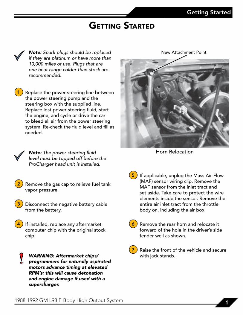
6 Remove the rear horn and relocate it forward of the hole in the driver’s side fender well as shown.
7 Raise the front of the vehicle and secure with jack stands.
GettInG started
Horn Relocation
New Attachment Point

22222 1988-1992 GM L98 F-Body High Output System
Getting Started
8 Remove the radiator cap. Using the petcock located on the lower passenger’s side of the radiator, drain approximately 1/4 of the coolant from the radiator into a clean container for either proper disposal or reuse.
9 Remove the plastic curved lower center air dam located between the front fascia and the radiator/condenser assembly. This piece will not be re-used.
10 Remove (cut) the center lower fascia support ear(s) flush with the fascia flange. These ears support the rear lower flange of the front facia.
11 To ease access to the crank pulley bolts, remove the sway bar just in front of the crank pulley.
12 Remove the three outer crank pulley bolts and the center balancer bolt. While holding the stock crank pulley in place, insert the crank pulley spacer into the stock crank pulley and re-install the balancer bolt. Attach the ProCharger pulley with the supplied 3/8-16 X 4-1/2” bolts and washers. Torque the balancer bolt to 65 lb-ft.
13 Reattach the sway bar if removed.
14 Locate the three relays on the driver’s side of the fire wall. The outer and center relays control the two electric radiator cooling fans. Using the supplied black 16 gage 8” wires and electrical “T”’s, ground the green wire on the center relay and the white wire on the outer relay using the OEM ground screw located on the driver’s side fender adjacent to the relays.
15 If applicable, extend the mass airflow harness by splicing in the supplied 5-wire harness using butt connectors (or solder for best connection).
Warning: Mismatching of wires could damage the MAF sensor!
16 Firebird/T.A. only: Remove the rear hold-down screw from the vacuum cannister. Rotate the cannister inward and forward enough to clear the hole in the fender well. Drill a hole in the new location and reattach using the original screw.
Trim Fascia Support Ears

33331988-1992 GM L98 F-Body High Output System 3
Oil Drain/Feed Setup
Oil Drain Setup
Note: This section applies to oil-fed blowers only (ex: P600B or D1). For self contained (SC) applications, proceed to the next section.
Warning: This is a gravity feed system; the oil-return line must be kink-free and run downhill for it’s entire length, draining into the pan above the oil-level line.
1 Using a small punch, punch a pilot hole in the front left corner of the oil pan, located directly beneath the front driver’s side oil pan bolt, 2-1/2” down from the flange. Stepping up punch sizes sequentially, enlarge the pilot hole to approximately 9/16” diameter (large enough to start a 3/8” NPT tap).
Warning: Do not use an excessively long punch as damage to internal engine parts may occur.
2 Pack the 3/8” NPT tap with heavy grease and tap to a depth approximately 1/4”.
Note: 3/8” NPT refers to the pipe’s inner diameter; the threads outer diameter is tapered and substantially larger than a standard 3/8” tap.
3 Clean the threads and remove all chips (a magnet works well).
4 Liberally apply silicon sealer and attach the 3/8” NPT - 1/2” barb fitting to the oil pan – do not connect the oil drain line at this point, as it should be connected to the ProCharger first.
5 Perform an oil and filter change (synthetic oil is highly recommended) prior to completing installation and starting the engine.
oIl draIn/feed setup
Oil Drain Location

44444 1988-1992 GM L98 F-Body High Output System
Oil Drain/Feed Setup
Oil Feed Setup
1 Remove the wiring clip from the oil pressure sending unit, located just above the oil filter.
2 Unscrew the sending unit from the block.
3 Install the oil feed “T” fitting on the block with the extension between the “T” and the block. The center port of the “T” should be facing forward and down at a 45º angle. Position the 90º fitting in the end of the “T” so that it is pointing forward and up at a 45º angle.
4 Install the oil pressure sending unit into the center port of the “T” so that it faces down and forwards. Reattach the wiring harness.
5 Attach the oil feed line to the 90º fitting in the end of the “T”. Do not use Teflon™ tape or sealant on the fitting, as this could block the ProCharger oil inlet.
6 Route the oil feed line forward and wire tie so that there are no kinks and the line is away from exhaust components or other sources of extreme heat.
Warning: Failure to secure the oil feed line can lead to burn-through and loss of oil pressure, resulting in severe engine damage.
Oil Feed Location and Orientation
90º Elbow “T” Fitting Brass Extension

55551988-1992 GM L98 F-Body High Output System 5
Intercooler and Tubing19
88-1
992
GM
F-B
od
y 2
Co
re In
terc
oo
ler
Sche
mat
ic
Ho
ses:
A.
3” 9
0° R
ubb
er E
lbow
(t
rim
med
1.5
” on
one
end
)B
. 3”
90°
Rub
ber
Elb
owC
. 3”
ID R
ubb
er C
onne
ctor
D.
2 C
ore
Inte
rcoo
ler
E.
4”ID
Rub
ber
Con
nect
orF.
M
AF
Sens
or (1
988-
1989
)
Tub
es:
1.
3” 4
5° T
ube
(AIG
C2I
-6)
2.
3” “
S” T
ube
w/S
urg
e B
ung
(AIG
C2I
-5)
3.
3” D
oub
le 4
5° T
ube
(AIG
C2I
-4)
4.
3” E
xten
ded
90°
Tub
e (A
IFA
2I-4
)5.
3”
Ext
end
ed O
ffse
t (lo
ng) -
Sp
eed
Den
sity
- (A
IGC
2I-2
1)6.
C
ast
Inta
ke T
ube
(AIG
C2I
-1)
7.
3” E
xten
ded
Off
set
(sho
rt) T
ube
(AIG
C2I
-2)

66666 1988-1992 GM L98 F-Body High Output System
Intercooler and Tubing
1988
-199
2 G
M F
-Bo
dy
3 C
ore
Inte
rco
ole
r Sc
hem
atic
Tub
es:
1.
3” 4
5° T
ube
(AIG
C2I
-6)
2.
3” “
S” T
ube
w/S
urg
e B
ung
(AIG
C3I
-5)
3.
3” D
oub
le 4
5° T
ube
(AIG
C3I
-4)
4.
3” E
xten
ded
90°
Tub
e (A
IFA
2I-4
)5.
3”
Ext
end
ed O
ffse
t (lo
ng) -
Sp
eed
Den
sity
- (A
IGC
2I-2
1)6.
C
ast
Inta
ke T
ube
(AIG
C2I
-1)
7.
3” E
xten
ded
Off
set
(sho
rt) T
ube
(AIG
C2I
-2)
Ho
ses:
A.
3” 9
0° R
ubb
er E
lbow
(t
rim
med
1.5
” on
one
end
)B
. 3”
90°
Rub
ber
Elb
owC
. 3”
ID R
ubb
er C
onne
ctor
D.
3 C
ore
Inte
rcoo
ler
E.
4”ID
Rub
ber
Con
nect
orF.
M
AF
Sens
or (1
988-
1989
)

77771988-1992 GM L98 F-Body High Output System 7
Intercooler and Tubing
Note: Leave all clamps loose until you have installed all of the tubes and hoses. Adjust each hose and tube for best fit and then tighten all clamps. Hose installation can be eased if you first wet the metal tubes and fittings with a solution of dishwashing soap and water. Some hoses may require trimming for optimal fit.
Camaro
1 Remove the factory air filter housing located in front of the radiator core support.
2 Remove the factory washer bottle/pump assembly. This will not be reused. Using the supplied #12 sheet metal screw and aluminum bracket, bolt the supplied replacement washer bottle/pump assembly into the area previously occupied by the air filter assembly in the front nose section of the vehicle using one of the existing holes in the core support as shown.
3 Following the replacement pump instructions, run the supplied rubber line from the inlet of the pump over to the factory windshield washer hose. Connect these hoses using the supplied 3/16” barb as shown.
4 Using the supplied connectors, splice into the factory washer pump wiring harness as shown. Plug the supplied washer pump wiring harness into the pump connector.
Intercooler and tubInG
Factory Air Filter Housing Removed
Supplied Washer Bottle/Pump Installed
#12 Sheet Metal Screw Supplied Bracket
Washer Bottle/Pump Assembly
Washer Hose Installation
Supplied Hose from Tank Factory Washer Hose
3/8” Barb
88888 1988-1992 GM L98 F-Body High Output System
Intercooler and Tubing
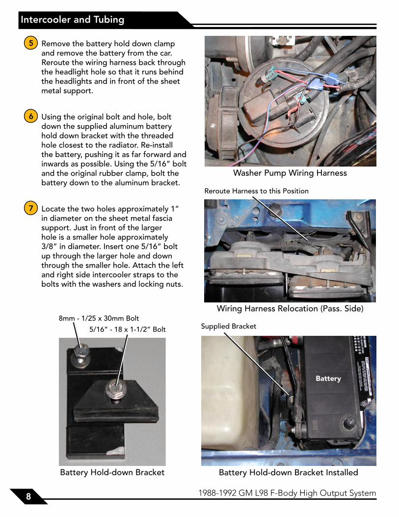
5 Remove the battery hold down clamp and remove the battery from the car. Reroute the wiring harness back through the headlight hole so that it runs behind the headlights and in front of the sheet metal support.
6 Using the original bolt and hole, bolt down the supplied aluminum battery hold down bracket with the threaded hole closest to the radiator. Re-install the battery, pushing it as far forward and inwards as possible. Using the 5/16” bolt and the original rubber clamp, bolt the battery down to the aluminum bracket.
7 Locate the two holes approximately 1” in diameter on the sheet metal fascia support. Just in front of the larger hole is a smaller hole approximately 3/8” in diameter. Insert one 5/16” bolt up through the larger hole and down through the smaller hole. Attach the left and right side intercooler straps to the bolts with the washers and locking nuts.
Washer Pump Wiring Harness
Wiring Harness Relocation (Pass. Side)
Reroute Harness to this Position
Battery Hold-down Bracket
5/16” - 18 x 1-1/2” Bolt
8mm - 1/25 x 30mm BoltSupplied Bracket
Battery Hold-down Bracket Installed
Battery

99991988-1992 GM L98 F-Body High Output System 9
Intercooler and Tubing
Firebird/Trans Am
1 Remove the cruise control diaphragm from the front corner of the shock tower. Relocate it to the rear corner of the shock tower using the original bracket.
2 Remove the factory washer bottle/pump assembly. This will not be reused. Using the supplied #12 sheet metal screw and aluminum bracket, bolt the supplied replacement washer bottle/pump assembly into the front nose section of the vehicle using one of the existing holes in the core support as shown.
3 Following the replacement pump instructions, run the supplied rubber line from the inlet of the pump over to the factory windshield washer hose. Connect these hoses using the supplied 3/16” barb as shown.
4 Using the supplied connectors, splice into the factory washer pump wiring harness as shown. Plug the supplied washer pump wiring harness into the pump connector.
Supplied Washer Bottle/Pump Installed
#12 Sheet Metal Screw Supplied Bracket
Washer Bottle/Pump Assembly
Washer Hose Installation
Supplied Hose from Tank Factory Washer Hose
3/8” Barb

1010101010 1988-1992 GM L98 F-Body High Output System
Intercooler and Tubing
5 Remove the battery hold down clamp and remove the battery from the car.
6 Using the original bolt and hole, bolt down the supplied aluminum battery hold down bracket with the threaded hole closest to the radiator. Re-install the battery, pushing it as far forward and inwards as possible. Using the 5/16” bolt and the original rubber clamp, bolt the battery down to the aluminum bracket.
7 Attach the intercooler support straps to the intercooler. Centering the intercooler on the car, hold the intercooler up to the sheet metal fascia support and mark the strap mounting holes on the support. Remove the straps from the intercooler. Drill the two holes using a 3/8” drill bit. From the top, insert one 5/16” bolt through each hole. Attach the left and right side intercooler straps to the bolts with the washers and locking nuts.
Washer Pump Wiring Harness
Wiring Harness Relocation (Pass. Side)
Reroute Harness to this Position
Battery Hold-down Bracket
5/16” - 18 x 1-1/2” Bolt
8mm - 1/25 x 30mm BoltSupplied Bracket
Battery Hold-down Bracket Installed
Battery

111111111988-1992 GM L98 F-Body High Output System 11
Intercooler and Tubing
Camaro/Firebird/TA
8 Remove the screw holding the hood latch support to the radiator support, just above the air dam. Using the original screw, attach the supplied center intercooler strap so that it faces forward and down.
9 Position the intercooler with all tabs on the bottom; side tabs forward. Place the intercooler scoop on the bottom side so that the scoop flange is against the intercooler tabs, and with the opening facing forward. Push the intercooler and scoop up into position horizontally in front of the radiator. Rest the intercooler and scoop on top of the previously installed straps. Bolt the straps, scoop, and intercooler together using the supplied 5/16” bolts.
10 Clamp one of the rubber 90° elbows (B) to the straight end of the “S” shaped tube (#2) with the open end facing approximately the same direction as the 1.5” surge fitting. From underneath the car, guide the end with the rubber elbow up through the driver’s side inner fender well, coming out of the hole previously occupied by the horn. Attach the bottom end to the intercooler inlet using the 3” ID rubber connector (C) and hose clamps.
Driver’s Side Intercooler Attachment
Center Intercooler Support
1212121212 1988-1992 GM L98 F-Body High Output System
Intercooler and Tubing
11 On the discharge side of the intercooler, attach the long tube with 45°’s on both ends (#3). 3 core intercooler tubes can go either way, 2 core tubes should have the longer end going to the intercooler
12 Clamp the other rubber 90° elbow (B) to the straight end of the extended 90° tube (#4), so that from the passenger’s side, when the short end faces forward, the tube goes up, and the open end of the elbow faces the driver’s side. Slide the tube, elbow up, through the passenger’s side inner fender well with the elbow discharging through the hole in the fender next to the battery. Attach the bottom end to the dual 45° tube (#3) with a 3” ID rubber connector (C) and hose clamps.
13 Insert the short end of the extended offset tube (#5 or 7) into the end of the elbow (B) on the passenger’s side with the straight end coming up, over the level of the battery, and clamp down.
14 Using the last 3” ID connector, attach the round end of the 90° tube with the oval (#6) to the extended offset tube, with the oval end facing the throttle body. If applicable, install the MAF sensor between these 2 tubes. Connect the oval end of the tube to the throttle body with the 4” ID connector (E) and 4” hose clamps.

131313131988-1992 GM L98 F-Body High Output System 13
Fuel System
Note: This section only applies to full systems, which include a fuel management unit and an in-line fuel pump. If you do not have a full system, additional fuel system modificatons will be required before starting the vehicle.
Warning: When working on high pressure fuel systems, caution should be taken when handling high pressure lines, as residual pressure may cause fuel to spray unless relieved prior to disconnection. Take precaution to avoid injury or fire.
Fuel Pump
1 Remove the bottom rear seat cushion.
2 Jack and properly support the driver’s side of the car.
3 Underneath the car, in front of the fuel tank, is a hump which corresponds to the back seat area. On the driver’s side, the fuel lines running from the fuel tank turn down and then forward at the bottom of the hump. On the way down before turning forward there is a fuel line clamp screwed to the body. Remove the screw, and attach the supplied fuel pump relay at this point.
4 Using the fuel pump bracket as a template, mark the three mounting hole locations just above and inward from the relay as shown. Drill out the three holes using a 5/16” bit. Insert the three supplied loose grommets into the holes.
5 From above, install the supplied 1/4” bolts through the holes. From below, push the fuel pump bracket onto the bolts and secure with washers and lock nuts. Be careful not to overtighten the nuts, as doing so will allow transmission of noise and vibration through the body of the car.
fuel system
Fuel Pump Installation(Viewed from Driver’s Side Rear Seat)
Fuel Pump
Fuel Pump Relay

1414141414 1988-1992 GM L98 F-Body High Output System
Fuel System
Fuel Pump Wiring Schematic
ATI In-Line Pump
Stock In-Tank Pump
Fuel Pump Relay
87
87
86
85
30
Open
Fuse
GND
GND
GND
Positive Power
Terminal
(From Stock Electrical Harness)
(+) (+)
(+) (-)
(+) (-)
6 Disconnect the fuel line from the discharge side of the fuel filter, where the fuel line makes a 90° turn. Connect the supplied fuel pump lines between the factory fuel lines and the filter.
7 Attach the yellow wire from relay #87 to the positive terminal of the in-line pump.
8 Attach the black ground wire from relay #86 to the ground terminal of the pump.
9 Using the supplied electrical “T” connector, connect the green wire from relay #85 to the grey wire in the stock fuel pump wiring harness (the three wires coming from the top center of the fuel pump running forward).
10 Attach the loose black ground wire between the ground on the in-line fuel pump and either another screw holding a fuel line clamp or a separate bolt or screw you drill a hole for.
11 Run the red wire from relay #30 along the bottom of the car, securing with wire ties, and attach it to the power terminal on the alternator, utilizing the supplied in-line fuse and ring connector.
151515151988-1992 GM L98 F-Body High Output System 15
Fuel System
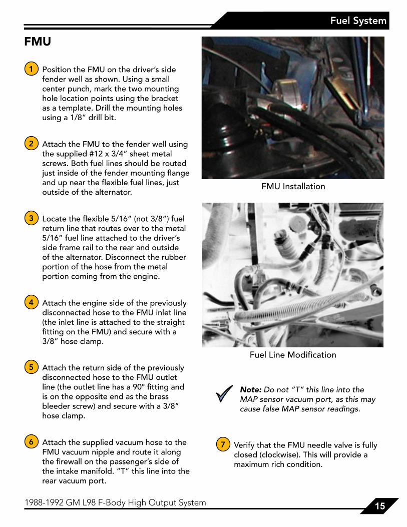
FMU
1 Position the FMU on the driver’s side fender well as shown. Using a small center punch, mark the two mounting hole location points using the bracket as a template. Drill the mounting holes using a 1/8” drill bit.
2 Attach the FMU to the fender well using the supplied #12 x 3/4” sheet metal screws. Both fuel lines should be routed just inside of the fender mounting flange and up near the flexible fuel lines, just outside of the alternator.
3 Locate the flexible 5/16” (not 3/8”) fuel return line that routes over to the metal 5/16” fuel line attached to the driver’s side frame rail to the rear and outside of the alternator. Disconnect the rubber portion of the hose from the metal portion coming from the engine.
4 Attach the engine side of the previously disconnected hose to the FMU inlet line (the inlet line is attached to the straight fitting on the FMU) and secure with a 3/8” hose clamp.
5 Attach the return side of the previously disconnected hose to the FMU outlet line (the outlet line has a 90° fitting and is on the opposite end as the brass bleeder screw) and secure with a 3/8” hose clamp.
6 Attach the supplied vacuum hose to the FMU vacuum nipple and route it along the firewall on the passenger’s side of the intake manifold. “T” this line into the rear vacuum port.
Note: Do not “T” this line into the MAP sensor vacuum port, as this may cause false MAP sensor readings.
7 Verify that the FMU needle valve is fully closed (clockwise). This will provide a maximum rich condition.
FMU Installation
Fuel Line Modification
1616161616 1988-1992 GM L98 F-Body High Output System
Fuel System
WARNING: Never strike the ProCharger pulley with a hammer or other tool under any circumstance! Evidence of such force will void the warranty, as serious damage to the precision bearings within the ProCharger could occur.
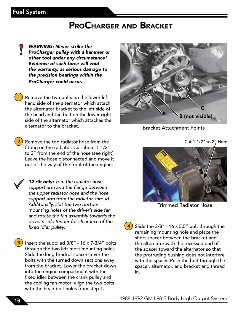
1 Remove the two bolts on the lower left hand side of the alternator which attach the alternator bracket to the left side of the head and the bolt on the lower right side of the alternator which attaches the alternator to the bracket.
2 Remove the top radiator hose from the fitting on the radiator. Cut about 1-1/2” to 2” from the end of the hose (see right). Leave the hose disconnected and move it out of the way of the front of the engine.
12 rib only: Trim the radiator hose support arm and the flange between the upper radiator hose and the hose support arm from the radiator shroud. Additonally, slot the two bottom mounting holes of the driver’s side fan and rotate the fan assembly towards the driver’s side fender for clearance of the fixed idler pulley.
3 Insert the supplied 3/8” - 16 x 7-3/4” bolts through the two left most mounting holes. Slide the long bracket spacers over the bolts with the turned down sections away from the bracket. Lower the bracket down into the engine compartment with the fixed idler between the crank pulley and the cooling fan motor; align the two bolts with the head bolt holes from step 1.
4 Slide the 3/8” - 16 x 5.5” bolt through the remaining mounting hole and place the short spacer between the bracket and the alternator with the recessed end of the spacer toward the alternator so that the protruding bushing does not interfere with the spacer. Push the bolt through the spacer, alternator, and bracket and thread in.
procharGer and bracket
Bracket Attachment Points
AC
B (not visible)
Trimmed Radiator Hose
Cut 1-1/2” to 2” Here

171717171988-1992 GM L98 F-Body High Output System 17
ProCharger and Bracket
SC/Bracket Install
5 Thread the two longer bolts into their corresponding holes in the head. Tighten all three mounting bolts securely.
6 Lower the ProCharger down into the engine compartment behind the bracket and next to the alternator.
7 Insert the two 5/16” socket head bolts and the two 3/8” socket head bolts through the ProCharger mounting holes in the bracket. Place a .750” spacer over the end of each bolt. Line up the bolts with the mounting holes in the ProCharger and tighten the bolts down. Add one bottle of the supplied ATI supercharger oil (6 ounces for a P1SC-1 or D1SC) to the ProCharger head unit.
8 Route the supplied belt around the crank pulley, with the bottom loop of the belt riding on top of both the fixed and the adjustable idler pulleys, and around the driven pulley on the ProCharger. Tension the belt by tightening the adjusting bolt on the very top of the mounting bracket.
Warning: Do not overtighten the belt. Excessive belt tension can damage or break the harmonic balancer. You should be able to twist the belt 1/4 turn when tightened properly.
9 When the desired tension is reached, firmly tighten the two fixed position bolts that the bracket grooves ride on. Using a straight edge, verify alignment of the crankshaft pulley to the driven pulley. Shim the supercharger or bracket if necessary to achieve proper alignment prior to starting the car.
10 Connect the supplied support bracket to the main supercharger bracket using the two 1/4” - 20 x 1” button head screws and 1/4” flat washers as shown. Connect the other end of the support bracket to the alternator using the supplied 8mm x 1.25 x 50mm stud. Secure the assembly with the supplied 8mm speed nut and lock washer.
11 Proceed to step 12.
SC Main Bracket Bolt Holes
A C
B (not visible)
SC Main Bracket Support
Support Bracket 8mm Stud

1818181818 1988-1992 GM L98 F-Body High Output System
ProCharger and Bracket
P600B/Bracket Install
5 Thread the two longer bolts into their corresponding holes in the head. Tighten all three mounting bolts securely.
6 Attach the oil drain line to the bottom fitting on the ProCharger. Lower the ProCharger down into the engine compartment behind the bracket next to the alternator. Route the drain line away from the exhaust manifold (or any other sources of extreme heat) and down to the oil return fitting in the pan. Cut the drain line to length at the drain fitting, making sure that the line runs continuously downhill without kinks or tight bends. Clamp the drain line to the fitting.
7 Insert the three 5/16” bolts through the ProCharger mounting holes in the bracket. Place a short spacer over the end of each bolt. Line up the bolts with the mounting holes in the ProCharger and tighten the bolts down.
8 Run the oil feed line over to the oil feed fitting on the side of the ProCharger, again making sure that it is away from heat sources and is not kinked in any way. Thread the line onto the fitting and secure tightly.
9 Route the supplied belt around the crank pulley, with the bottom loop of the belt riding on top of both the fixed and the adjustable idler pulleys, and around the driven pulley on the ProCharger. Tension the belt by tightening the adjusting bolt on the very top of the mounting bracket.
Warning: Do not overtighten the belt. Excessive belt tension can damage or break the harmonic balancer. You should be able to twist the belt 1/4 turn when tightened properly.
10 When the desired tension is reached, firmly tighten the two fixed position bolts that the bracket grooves ride on. Using a straight edge, verify alignment of the crankshaft pulley to the driven pulley. Shim the supercharger or bracket if necessary to achieve proper alignment prior to starting the car.
11 Proceed to step 12.
P600B Main Bracket Bolt Holes
AC
B

191919191988-1992 GM L98 F-Body High Output System 19
ProCharger and Bracket
D1/Bracket Install
5 Thread the two longer bolts into their corresponding holes in the head. Tighten all three mounting bolts securely.
6 Attach the oil drain line to the bottom fitting on the ProCharger. Lower the ProCharger down into the engine compartment behind the bracket next to the alternator. Route the drain line away from the exhaust manifold (or any other sources of extreme heat) and down to the oil return fitting in the pan. Cut the drain line to length at the drain fitting, making sure that the line runs continuously downhill without kinks or tight bends. Clamp the drain line to the fitting.
7 Insert the five 5/16” bolts through the ProCharger mounting holes in the bracket. The tensioner will need to be removed and re-installed after bolt installation. Place a 1.300” spacer over the end of each bolt. Line up the bolts with the mounting holes in the ProCharger and tighten down.
8 Run the oil feed line over to the oil feed fitting on the side of the ProCharger, again making sure that it is away from heat sources and is not kinked in any way. Thread the line onto the fitting and secure tightly.
9 Route the supplied belt around the crank pulley, with the bottom loop of the belt riding on top of both the fixed and the adjustable idler pulleys, and around the driven pulley on the ProCharger. Tension the belt by tightening the adjusting bolt on the very top of the mounting bracket.
Warning: Do not overtighten the belt. Excessive belt tension can damage or break the harmonic balancer. You should be able to twist the belt 1/4 turn when tightened properly.
10 When the desired tension is reached, firmly tighten the two fixed position bolts that the bracket grooves ride on. Using a straight edge, verify alignment of the crankshaft pulley to the driven pulley. Shim the supercharger or bracket if necessary to achieve proper alignment prior to starting the car.
11 Proceed to step 12.
D1 Main Bracket Bolt Holes
A
C
B

2020202020 1988-1992 GM L98 F-Body High Output System
ProCharger and Bracket
12 Clamp the 4” to 3.5” reducer to the 4” 45° elbow with the surge fitting. Attach the long end of the surge valve hose to the surge fitting in the elbow and clamp down. Attach the air filter to the 3.5” end of the reducer.
13 Lower the air filter assembly into the compartment behind the ProCharger. Route the surge hose down alongside the power steering pump and over to the surge fitting on tube #2 (going into the intercooler). Be sure that the hose does not come into contact with the steering linkage. Clamp the short end of the surge hose to the fitting on the intercooler tube. Route the vacuum line from the surge valve up to the MAP sensor vacuum port on the passenger’s side or any other good vacuum source, as long as the surge valve and FMU are not on the same source.
14 Re-attach the upper radiator hose.
Note: If using the 12-rib drive system, you will need to trim approximately 1” off the end of the upper radiator hose.
15 On the back of the ProCharger, attach the air filter assembly so that the filter does not contact the valve cover. Clamp down tightly.
16 In the open end of the rubber elbow (B) coming out of the fender hole on the driver’s side, clamp down the curved end of the short cut-off 45° tube (#1). Attach the longer end of the trimmed 90° rubber elbow (A) to the long end of the 45° tube. Attach the trimmed end to the ProCharger outlet.
ProCharger Air Intake Tract

212121211988-1992 GM L98 F-Body High Output System 21
Finishing
1 Locate the crankcase vent tube on the passenger’s side valve cover. This hose routes up to a nipple on the throttle body housing. Disconnect this hose at the throttle body and rotate the hose so that it vents to atmosphere underneath the A/C accumulator. Cap the throttle body nipple with the supplied rubber cap and secure with a wire tie.
2 Locate the PCV valve on the driver’s side valve cover. Remove the hose from the PCV valve and the nipple on the intake manifold. Cap the manifold nipple with the supplied rubber cap and secure with a wire tie. Attach the supplied 3/8” x 16” hose to the PCV valve and route it back and just inside the driver’s side frame rail. This hose also vents to atmosphere.
fInIshInG
Congratulations! You have successfully completed the installation of your new ProCharger supercharger system!
Please continue reading the following pages for important information about how to maintain your system.

2222222222 1988-1992 GM L98 F-Body High Output System
Tuning
Note: Too much fuel will cause the car to hesitate, be sluggish, emit heavy black smoke and not attain intended boost levels. A lean condition will cause the car to detonate (which, under higher boost conditions, can cause blown head gaskets), run hot or break up. The FMU can be adjusted via the air bleed needle valve on the top of the unit. Since each car is different and engine and exhaust modifications will affect your final fuel pressure settings, the following is a guide offered to help you arrive at your final FMU setting. Although the stock injectors are adequate for 9 psi kits, performance can be enhanced by switching to 24 lb/hr injectors.
1 For best performance and reliability it is best to run as much fuel pressure as possible without bogging or flooding the motor. When first test driving the car, the best method for tuning the fuel system is by using all or a combination of the following instrumentation: 1. Boost gauge
2. Fuel pressure gauge, 0 - 100 psi
3. Fuel/air ratio meter If using a fuel/air ratio meter, the meter should show lean under idle, low throttle and steady-state cruise conditions. Under hard acceleration and high boost conditions the meter should read rich (between 11.0 and 11.8). When using a fuel pressure gauge, the fuel pressure should read 35 - 45 psi at idle, low throttle and steady-state cruise
conditions. Under hard acceleration, the fuel pressure should increase linearly with boost up to approximately 7 psi and should peak at 70 - 75 psi (assuming a 9 psi kit and stock injectors).
2 Initial driving should be performed under maximium rich conditions (FMU needle valve fully closed) and slowly leaning out in order to improve throttle response and performance. If the car hesitates upon snap acceleration or heavy black smoke is emitted from the tailpipe, reduce the fuel pressure under boost by turning the FMU needle valve counter clockwise approximately 1/4 turn at a time and finally in 1/16 turn increments. If the car detonates or breaks up under boost, increase fuel pressure by turning the needle valve clockwise in 1/2 turn increments.
Note: Adjusting the FMU needle valve will not affect idle, low throttle or steady-state fuel pressures.
Supplemental/Race/Off-road
3 Off-road, high boost applications require high energy ignition systems for proper combustion. If you are using a stock ignition system on such an application, the plug gap must be reduced to approximately .035” to avoid extinguishing the arc discharge. The use of spark plugs one heat range colder than stock is also advised.
tunInG

232323231988-1992 GM L98 F-Body High Output System 23
Installation Review/Safety Check
1 Carefully review the entire installation. Examine oil and fuel lines routed near moving parts and exhaust components to ensure that they are protected from chafing or abrasion, secure and free of twists and kinks. All wires and hoses should be firmly secured with clamps or wire ties.
2 Ensure that the air filter is installed.
3 Check and correct all fluid levels.
Note: If you did not perform an oil and filter change after the oil drain setup, it should be performed now before proceeding further (oil-fed blowers only).
4 Start the engine and let it idle for a few minutes. Inspect for air or fluid leaks.
Warning: Aftermarket chips, unless specifically designed for use with a supercharger, advance timing at elevated rpm’s, and in most cases will cause detonation and engine damage under boost conditions.
5 Shut off the engine and check for fluid leakage, signs of rubbing parts, and other potential problems.
6 Be sure you have purchased and installed a fuel pressure gauge and/or fuel-air ratio meter to monitor fuel delivery while driving. Installation of a boost pressure gauge is also recommended.
Note: Larger cities (especially in winter months) often use oxygenated or reformulated fuels to reduce pollution. Although these fuels have the same octane ratings as unaltered fuels, some people have experienced problems (detonation) with their use. If you experience similar problems, it is advised to reduce your timing or use octane booster to avoid detonation.
Warning: The supercharger contains no oil from the factory. The unit must be filled prior to use. Use only ATI supplied oil in your ProCharger. The ATI oil has been specially formulated for the bearings in the ProCharger and use of oil other than that supplied by ATI will void your warranty.
InstallatIon revIew/safety check

2424242424 1988-1992 GM L98 F-Body High Output System
Operation and Maintenance
Crank Pulley Diameter / Blower Pulley Diameter X Step-up Ratio X Max engine RPM = Blower RPM
/ X 4.10 X =
Supercharger P600B P1SC D1 D1SC
Max Impeller Speed 60,000 62,000 65,000 62,000
Gear Ratio 3.05:1 4.10 4.10 4.10
operatIon & maIntenance
Cold StartingNever race your engine (and ProCharger) when your engine is cold. Allow the water temperature to climb into operating range for several minutes before driving above 2,500 rpm, to ensure adequate oil lubrication.
Fuel QualityFor best performance and reliability, always use premium grade fuel (91 octane or higher). Always listen for signs of detonation after refueling, and after replacement or modification of any fuel system components. Back off throttle should detonation occur. With a properly installed ProCharger intercooled supercharger system, detonation should not be an issue.
Ignition System MaintenanceIf your spark plugs are more than a year old or have more than 10,000 miles logged, you should consider changing them before driving your vehicle under load. Additionally, spark plug wires should be changed if visibly damaged or whenever resistance exceeds factory specifications.
Air Filter MaintenanceYour air filters should be cleaned periodically, potentially as often as every 10,000 miles or 6 months, even though a service interval of 50,000 - 100,000 miles is quoted by the manufacturer under normal driving conditions. A clogged air filter will result in decreased boost levels and vehicle performance. K&N air filter cleaner is recommended, and be sure to re-oil the cleaned filter before re-installing. Always operate your vehicle with an air filter; failure to do so may result in damage to your ProCharger and/or personal injury!
Belt ReplacementThe belt which turns your ProCharger will stretch after initial run-in, and should be re-tightened after approximately the first hundred miles. After possibly one more tightening of the belt with the tensioner, further stretching should not occur. Tighten the belt sufficiently to avoid slippage, but do not overtighten, as this could cause damage to the ProCharger’s precision bearings. When removing belts, ensure that they are re-installed to turn in the same direction as before. Should you reuse a thrown belt and find that it needs frequent re-tightening, the belt is damaged and should be replaced. Belts can be purchased from ATI or from your local parts store. Gates Micro-V belts are recommended; these belts are available at CarQuest®, NAPA® and other auto parts stores. Your nearest CarQuest store can be found by dialing 800-492-7278, the nearest NAPA store at 800-538-6272.
Impeller SpeedMaximum impeller speed should not exceed the redline of the blower; see table below or contact ATI. Maximum impeller speed = crankshaft pulley diameter (N1) divided by supercharger pulley diameter (N2), multiplied by the step-up gear ratio of the blower, multiplied by maximum engine rpm.
Impeller RPM = (N1/N2) X Step-up Ratio X Engine RPM
25252525 1988-1992 GM L98 F-Body High Output System
Operation and Maintenance
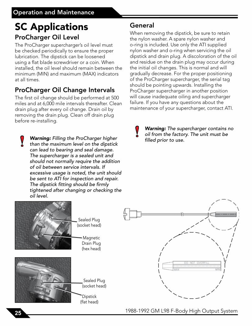
Magnetic Drain Plug (hex head)
Sealed Plug (socket head)
Dipstick (flat head)
Sealed Plug (socket head)
SC ApplicationsProCharger Oil LevelThe ProCharger supercharger’s oil level must be checked periodically to ensure the proper lubrication. The dipstick can be loosened using a flat blade screwdriver or a coin. When installed, the oil level should remain between the minimum (MIN) and maximum (MAX) indicators at all times.
ProCharger Oil Change IntervalsThe first oil change should be performed at 500 miles and at 6,000 mile intervals thereafter. Clean drain plug after every oil change. Drain oil by removing the drain plug. Clean off drain plug before re-installing.
Warning: Filling the ProCharger higher than the maximum level on the dipstick can lead to bearing and seal damage. The supercharger is a sealed unit and should not normally require the addition of oil between service intervals. If excessive usage is noted, the unit should be sent to ATI for inspection and repair. The dipstick fitting should be firmly tightened after changing or checking the oil level.
GeneralWhen removing the dipstick, be sure to retain the nylon washer. A spare nylon washer and o-ring is included. Use only the ATI supplied nylon washer and o-ring when servicing the oil dipstick and drain plug. A discoloration of the oil and residue on the drain plug may occur during the initial oil changes. This is normal and will gradually decrease. For the proper positioning of the ProCharger supercharger, the serial tag should be pointing upwards. Installing the ProCharger supercharger in another position will cause inadequate oiling and supercharger failure. If you have any questions about the maintenance of your supercharger, contact ATI.
Warning: The supercharger contains no oil from the factory. The unit must be filled prior to use.

2626262626 1988-1992 GM L98 F-Body High Output System
Limited Warranty
lImIted warranty
Accessible Technologies, Inc. (ATI) provides a limited twelve (12) month warranty on the ProCharger supercharger (36 months for P600B) against defects in materials and workmanship unless otherwise specified. This limited warranty starts on the date of original purchase from your local dealer, or date of shipment from the factory. This limited warranty coverage is extended only to the original owner and excludes hoses, sleeves, and electronic components manufactured by other companies. IF THE SUPERCHARGER’S DRIVE RATIO IS ALTERED IN ANY WAY FROM THE FACTORY SETTING, WARRANTY COVERAGE IS VOID. USE OF ANY PULLEY NOT MANUFACTURED OR SUPPLIED BY ATI VOIDS ALL WARRANTY COVERAGE. ATI’s warranty obligations are limited to the terms below:
ATI agrees to honor a warranty claim at its sole discretion and only after inspection at the ATI factory. No warranty will be honored if any part of the product is found to have been improperly installed, tampered with, mishandled, or misused in any way. Disassembly of the ProCharger supercharger or removal of the ProCharger supercharger’s serial plate voids all warranties. Claims for freight damages should be directed to the freight company.
If ATI’s limited warranty applies, your product will be repaired or replaced at ATI’s discretion and shipped back. If the limited warranty does not apply, ATI will advise you of the specific reason, cost of the repair, and delivery time. After advising you of this information we will, at your option, either proceed with repairs or return your product to you in the state in which it was received. In either case the product will be shipped to you, insured at replacement value. Therefore, you will pay the return shipping and insurance charges if ATI’s limited warranty does not apply to your product.
THE WARRANTY AND REMEDIES SET FORTH ABOVE ARE EXCLUSIVE AND IN LIEU OF ALL OTHERS, ORAL OR WRITTEN, EXPRESS OR IMPLIED. THE DURATION OF ANY AND ALL WARRANTIES ON THE PRODUCTS DISCUSSED ARE LIMITED TO THE PERIOD IDENTIFIED ABOVE. ATI IS NOT RESPONSIBLE IN ANY EVENT FOR DIRECT, SPECIAL, INCIDENTAL OR CONSEQUENTIAL DAMAGES. No ATI dealer, agent, or employee is authorized to make any modification, extension, or addition to this warranty.
To obtain service under this warranty you must do the following during the warranty period:
Phone ATI (913-338-2886) and provide us with the following information:
- ProCharger supercharger serial number. - Vehicle year, make, model, engine modifications, and other modifications. - Description of perceived issue.
If a solution to your issue can not be found after the above phone consultation, you will be assigned a return authorization number (RMA). You must then properly package and ship your product, at your expense, to the ATI factory. The product should be carefully packaged in a rugged box.
Include the following information inside the box with your product:
- Copy of your original invoice or receipt. - Name, address, and daytime telephone number. - Return authorization number (RMA). - Vehicle year, make, model, engine modifications, and other modifications. - Description of perceived issue.
Clearly mark the warranty claim number on the top and one side of the box in characters at least 2” tall. Properly package the product and ship it, prepaid and insured for the retail value of the component(s) being returned, to the following address:
Accessible Technologies, 14801 West 114th Terrace, Lenexa, Kansas 66215

272727271988-1992 GM L98 F-Body High Output System 27
ProCharger Extended Coverage
procharGer extended coveraGe (sc)
The ProCharger Extended Coverage Program extends the ProCharger warranty coverage for an additional twenty-four (24) months, for a total of thirty-six (36) months or three years of coverage. This extended coverage applies to parts for the ProCharger supercharger head unit only and does not include other system components. With your extended coverage registration, you will receive two (2) additional boxes of ProCharger Supercharger oil.
Under the extended coverage program, Accessible Technologies, Inc. (ATI) will repair or replace any component within the supercharger head unit which is found to be defective. Only the supercharger head unit itself is included in the extended coverage.
Service under the extended coverage program is obtained through the same process as described in the Limited Warranty.
Race kits are not eligible for the ProCharger Extended Coverage Plan
To qualify for the ProCharger Extended Coverage:
• Only the original owner of the ProCharger supercharger is eligible.
• Completion of the Extended Coverage Registration Form is required, along with a $49 registration fee. This form must be completed in its entirety, and must be submitted along with payment within 30 days from the date of original purchase from your local dealer or date of shipment from the factory.
• Participants must have a ProCharger P-1SC, P-1SC-1, C1, or C2 supercharger head unit using the maximum warranted boost level. All terms and conditions within “The Limited Warranty” apply. Acts resulting in disqualification include but are not limited to the following:
- Disassembly or modification the ProCharger supercharger.
- Removal or attempted removal of the ProCharger drive pulley(s).
- Removal or attempted removal of the ProCharger supercharger serial number plate.
- Removal or attempted removal of the compressor housing or transmission case.
• Participants agree to properly maintain the ProCharger supercharger and provide proof of compliance with the following recommended maintenance:
- Change the ProCharger supercharger oil after the initial break-in period of 500 miles (automotive) or 15 hours (marine).
- Change the ProCharger supercharger oil every 6,000 miles after the initial break-in period.
- Use only the specified amount of ProCharger Supercharger oil in the ProCharger supercharger.
- Inspect and clean the magnetic drain plug at every ProCharger supercharger oil change.
- Check the ProCharger supercharger oil level frequently.

2828282828 1988-1992 GM L98 F-Body High Output System
Notes

ProCharger Extended Coverage Program Registration Formcu
t al
ong
the
do
tted
line
cut
alo
ng t
he d
ott
ed li
ne
Name:_________________________________
Address:_______________________________
City:___________________________________
State:________________ Zip:____________
Daytime phone:_________________________
Evening phone:_________________________
E-mail:_________________________________
Age 18 - 24 25 - 34 35 - 44 45 - 54 55 and up
Income $15,000 - $29,000 $30,000 - $44,000 $45,000 - $69,000 $70,000 and up
What magazines do you read?
Car & Driver Car Craft Chevy High Performance Four Wheel and Off Road Hot Rod Motor Trend Muscle Mustangs and Fast Fords GM High-Tech Performance 5.0 Mustang Super Street Mustang Monthly Truck Trends Popular Hot Rodding Road & Track Sport Truck Super Chevy Truckin’ Street Truck
Date of Purchase:_______________________
Purchased From:_______________________
ProCharger Serial #:_____________________
Vehicle Year:___________________________
Vehicle Make:__________________________
Vehicle Model:_________________________
Please rank in order of importance starting with 1 being most important.
Which information sources most influenced your decision to purchase a ProCharger system?
___ Magazine advertising ___ Dealer recommendation ___ ProCharger Brochures ___ Witnessed performance on a car ___ Test drive ___ Magazine editorials ___ Friends ___ Conversations with ATI technicians ___ Web Site (please specify)___________ ___ Other (please specify)__________
What most influenced your decision to purchase a ProCharger system?
___ Reliability ___ Standard warranty ___ Extended coverage warranty ___ Performance ___ Quiet operation ___ Removability (ability to return car to stock) ___ Cost ___ Ease of Installation
Who installed your ProCharger system? Self Dealer Other ________________________ Have you own a forced induction system previously? Yes No If yes: Supercharger: Brand(s)_______________________ Vehicle(s)_____________________________
Turbocharger: Brand(s)_______________________ Vehicle(s)_____________________________
I have read and understand the policy for the ProCharger Extended Coverage Program. I have not and will not modify my ProCharger supercharger in any way during my participation in the extended coverage program. I have read and answered all questions on this form. I have enclosed my check for $49, payable to ATI, for enrolling my ProCharger supercharger (serial number indicated above) in the extended coverage program for an additional twenty-four (24) months beyond the standard limited warranty period of twelve (12) months.
Signature_____________________________________________ Date_____________________
Mail this completed registration form with a $49 check to ATI at: 14801 West 114th Terrace, Lenexa, KS 66215. If you have any questions, contact us at [email protected] or (913) 338-2886 8:30 AM - 5:30 PM CST, Monday - Friday.
Return this completed form and a $49 check within 30 days of original purchase.

This Page is Intentionally Left Blank

This Page is Intentionally Left Blank

Accessible Technologies, Inc. ©2008 ATI, All Rights Reserved
Part Number PMGC1A-001 Rev. B
Accessible Technologies, Inc. 14801 W. 114th Terrace
Lenexa, KS 66215 Phone: 913.338.2886
Fax: 913.338.2879 [email protected]
*PMGC1A-001*