1983: stress analysis for prolonging tube life
TRANSCRIPT

Stress Analysis for Prolonging Tube Life
The operational variables and the material properties essential forprolonging tube life are studied by the computer creep stressanalysis.
Takao Kawai, Takaaki MohriKatsuaki Takemura, and Toshikazu Shibasaki
Chiyoda Chemical Engineering & Construction Co., Ltd.Yokohama, Japan
The l ife of catalyst tubes to be used unaer hightemperature and high pressure is a matter ofprimary concern for the user because it relatesto the safety and reliability of ammonia plants.Prediction of residual l i fe of catalyst, tubesand the study of tube l i fe prolongation arebeing done in different organizations.
The factors that affect, tube l i fe can beclassified as:
1) creep rupture properties of themateri al
2) macrostructure of base metal andweldment
3) stress due to the thermal gradient ofthe tube wall
4) stress due to internal pressure
5) plant operation procedures
Papers on the first two factors werepresented by the authors in previous AIChEannual meetings (1),(2),(3). In these presenta-tions, it was shown that creep damage of HK40catalyst tubes were mainly caused by thermalstresses. Also, it was shown that macrostruc-ture inferior in stress relaxation properties aswell as brittleness in aged HK40 materialaccelerates creep damage. Further, it waspointed out that application of IN519 materialwith good creep rupture ductility after agingand control of catalyst tube macrostructure are
essential for prolonging tube life.This paper reports the material propertie:
and operation variables essential for prolongingtube life. These were obtained from creejstress computer analyses based on destructivfexaminations of used HK40 and IN519 cat.alysltubes of ammonia plants.
ANALYSIS OF USED CATALYST TUBE
HK40 Catalyst Tube
The HK40 catalyst tubes subjected to thisanalysis are from an ammonia reformer furnacewhich was constructed and started up in December1965 and experienced 26 shutdowns from that timeto February 1972, a period of about 56,OOChours. In February 1972, four catalyst tubeswere taken out for destructive examinations.
An outline of tube dimensions and theoperating conditions is shown in Table 1.
Table 1. Outline of a primary reformer
Catalyst tubes1) Material2) Outside diameter3) Inside diameter4) Wall thicknessOperated conditions1) Total operation period2) Number of shutdowns3) Inlet pressure
HK40152mm (5.98").120mm (A.72")16mm (0.63")
=56,200 hours2725 kg/cmG(355.5 psig)
131
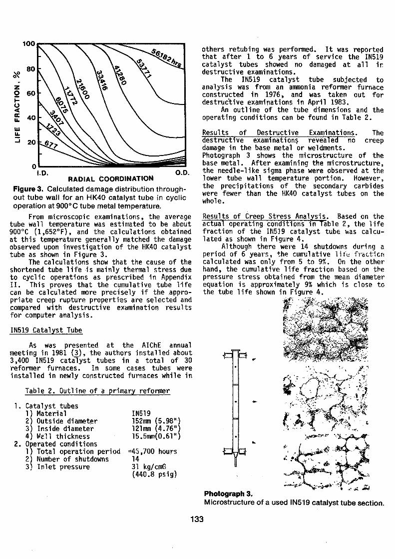
Results of Destructive Examination. As a result"o?th"edestructiveexaminations, many crackswere found in the base metal and weldments onthree of the four sample tubes. The cracksfound in the base metal were longitudinal cracksand uniformly distributed in the circumferentialdirection as shown in Photograph 1. However,leakage in this reformer wa;> not ct'oecttc' duringoperation in spite of the severe creep damagethroughout the tube wall.
Photograph 2 is a magnification of cracksseen in Photograph 1. Since many creep voidswere found around the cracks, the damage wasdefined as creep damage. Furthermore, from thedegree of Sigma phase precipitations, coarseningof the secondary carbides and coalescing of theprimary carbides, it was deduced that theaverage temperature used were approximately900°C (1,65?°F) though the design temperaturewas 890°C (1,634°F).
20
10
s|
0>
CO 20) *UlQC
CO 1
0.5
P 17.436. 4.621(LOG.f) 0.288UOG.j)2
12 13 14 15 16 17P= T (LOG t + 9.7)x10"3
18 19
Photograph 1.Creep damage around the circumference of an HK40catalyst tube section.
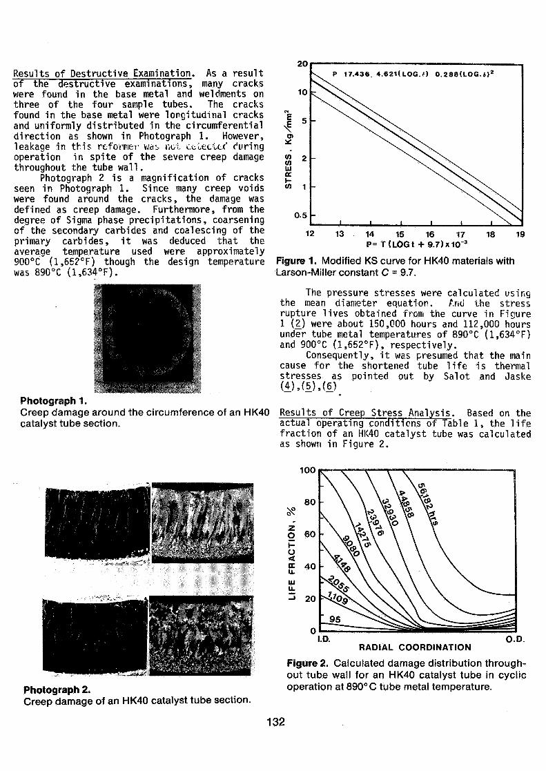
Figure 1. Modified KS curve for HK40 materials withLarson-Miller constant C = 9.7.
The pressure stresses were calculated usingthe mean diameter equation. And the stressrupture lives obtained from the curve in Figure1 (2) were about 150,000 hours and 112,000 hoursunder tube metal temperatures of 890°C (1,634°F)and 900°C (1,652°F), respectively.
Consequently, it was presumed that the maincause for the shortened tube life is thermalstresses as pointed out by Salot and Jaske(4),(5).(6)
e
Results of Creep Stress Analysis. Based on theactual operating conditions of Table 1, the lifefraction of an HK40 catalyst tube was calculatedas shown in Figure 2.
100
Photograph 2.Creep damage of an HK40 catalyst tube section.
RADIAL COORDINATIONO.D.
Figure 2. Calculated damage distribution through-out tube wall for an HK40 catalyst tube in cyclicoperation at 890° C tube metal temperature.
132
100
I.D.RADIAL COORDINATION
O.D.
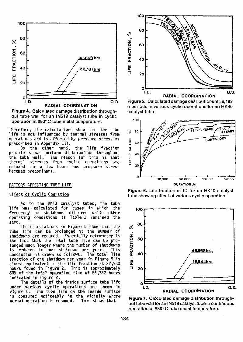
Figure 3. Calculated damage distribution through-out tube wall for an HK40 catalyst tube in cyclicoperation at 900°C tube metal temperature.
From microscopic examinations, the averagetube wall temperature was estimated to be about900°C (1,652°F), and the calculations obtainedat this temperature generally matched the damageobserved upon investigation of the HK40 catalysttube as shown in Figure 3.
The calculations show that the cause of theshortened tube life is mainly thermal stress dueto cyclic operations as prescribed in AppendixII. This proves that the cumulative tube lifecan be calculated more precisely if the appro-priate creep rupture properties are selected andcompared with destructive examination resultsfor computer analysis.
IN519 Catalyst Tube
As was presented at the AIChE annualmeeting in 1981 (3_), the authors installed about3,400 IN519 catalyst tubes in a total of 30reformer furnaces. In some cases tubes wereinstalled in newly constructed furnaces while in
Table 2. Outline of a primary reformer
Catalyst tubes1) Material2) Outside diameter3) Inside diameter4) Well thicknessOperated conditions1) Total operation period2) Number of shutdowns3) Inlet pressure
IN519152mm (5.98"121mm (4.76"15.5mm(0.61")
=45,700 hours1431 kg/cmG(440.8 psig)
others retubing was performed. It was reportedthat after 1 to 6 years of service the IN519catalyst tubes showed no damaged at all indestructive examinations.
The IN519 catalyst tube subjected toanalysis was from an ammonia reformer furnaceconstructed in 1976, and was taken out fordestructive examinations in April 1983.
An outline of the tube dimensions and theoperating conditions can be found in Table 2.
Results of Destructive Examinations. Thecreepdestructive exami nati ons revealed no
damage in the base metal or weldments.Photograph 3 shows the microstructure of thebase metal. After examining the microstructure,the needle-like sigma phase were observed at thelower tube wall temperature portion. However,the precipitations of the secondary carbideswere fewer than the HK40 catalyst tubes on thewhole.
Results of Creep Stress Analysis. Based on theactual operating conditions in Table 2, the lifefraction of the IN51.9 catalyst tube was calcu-lated as shown in Figure 4.
Although there were 14 shutdowns during aperiod of 6 years, the cumulative life fractioncalculated was only from 5 to 9%. On the otherhand, the cumulative life fraction based on thepressure stress obtained from the mean diameterequation is approximately 9% which is close tothe tube life shown in Figure 4.
r
r /î ''- •>•.>- • *;*'•»& • / . .-**L. . • •/.^^'^••'^-•\^
\^l >»***^':^1 A
Photograph 3.Microstructure of a used IN519 catalyst tube section.
133
100
100
oNo 80
O 60Hü
£ 40
uiu.3 20
45668 hrs
23J07hrs
I.D. O. D.RADIAL COORDINATION
Figure 4. Calculated damage distribution through-out tube wall for an IN519 catalyst tube in cyclicoperation at 880°C tube metal temperature.
Therefore, the calculations show that the tubelife is not influenced by thermal stresses fromoperations and is affected by pressure stress asprescribed in Appendix III.
On the other hand, the' life fractionprofile shows uniform distribution throughoutthe tube wall. The reason for this is thatthermal stresses from cyclic operations arerelaxed for a few hours and pressure stressbecomes predominant.
FACTORS AFFECTING TUBE LIFE
Effect of Cyclic Operation
As to the HK40 catalyst tubes, the tubelife was calculated for cases in which thefrequency of shutdowns differed while otheroperating conditions as Table 1 remained thesame.
The calculations in Figure 5 show that thetube life can be prolonged if the number ofshutdowns are reduced. Especially noteworthy isthe fact that the total tube life can be pro-longed much longer where the number of shutdownsis reduced to one shutdown per year. Thisconclusion is drawn as follows. The total lifefraction of one shutdown per year in Figure 5 isalmost equivalent to the life fraction at 32,930hours found in Figure 2. This is approximately60% of the total operation time of 56,182 hoursindicated in Figure 2.
The details of the inside surface tube lifeunder various cyclic operations are shown inFigure 6. The tube life on the inside surfaceis consumed noticeably in the vicinity wherenormal operation is resumed. This shows that
O
LUU.
I.D. O.D.RADIAL COORDINATION
Figures. Calculated damage distributions at 56,182h periods in various cyclic operations for an HK40catalyst tube.
100
rsWävEARS XIS.D./
10,000 20,000 30.000 40.000
DURATION, hr
Figure 6. Life fraction at ID for an HK40 catalysttube showing effect of various cyclic operation.
100
NPON80
O 60HU
£ 40
u.J 20
I.D.RADIAL COORDINATION
O.D.
Figure 7. Calculated damage distribution through-out tube wall for an IN519 catalyst tu be in continuousoperation at880°C tube metal temperature.
134
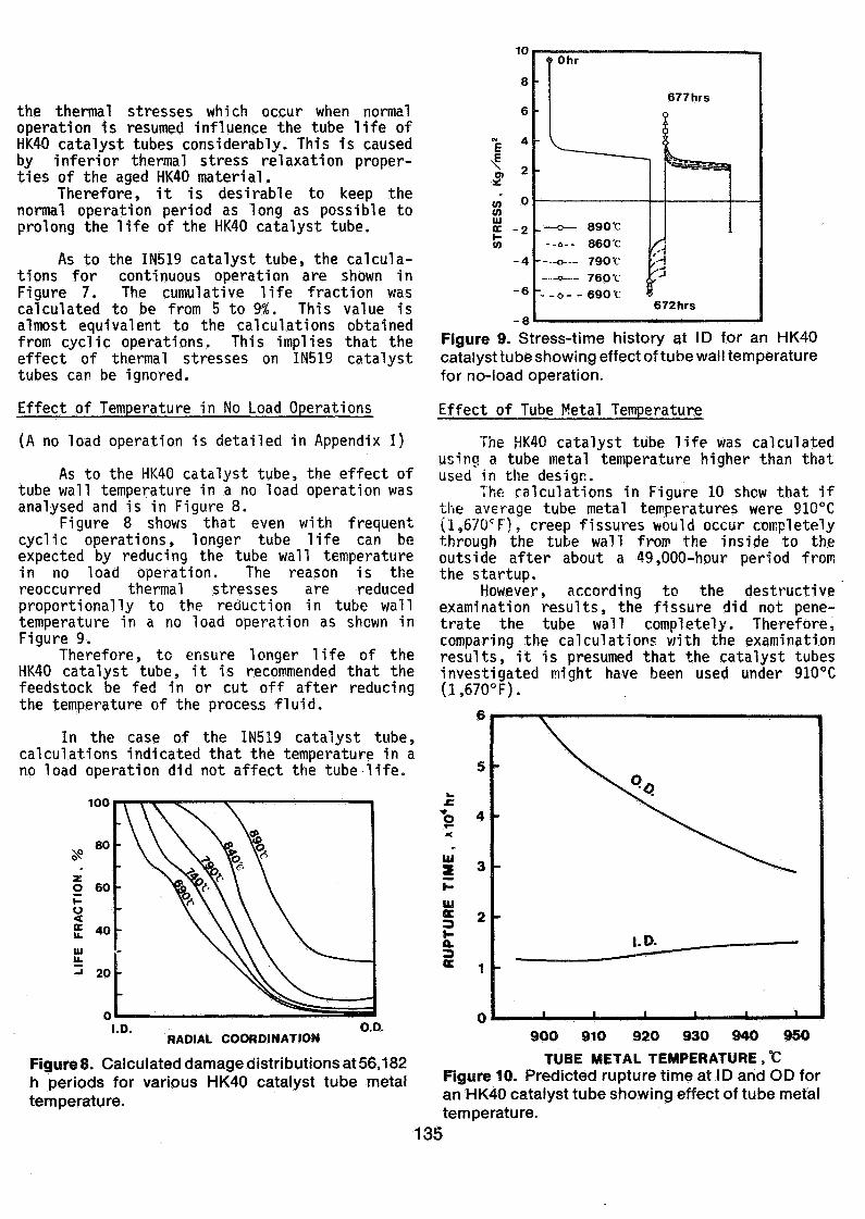
the thermal stresses which occur when normaloperation is resumed influence the tube life ofHK40 catalyst tubes considerably. This is causedby inferior thermal stress relaxation proper-ties of the aged HK40 material.
Therefore, it is desirable to keep thenormal operation period as long as possible toprolong the life of the HK40 catalyst tube.
As to the IN519 catalyst tube, the calcula-tions for continuous operation are shown inFigure 7. The cumulative life fraction wascalculated to be from 5 to 9%. This value isalmost equivalent to the calculations obtainedfrom cyclic operations. This implies that theeffect of thermal stresses on IN519 catalysttubes can be ignored.
Effect of Temperature in No Load Operations
(A no load operation is detailed in Appendix I)
As to the HK40 catalyst tube, the effect oftube wall temperature in a no load operation wasanalysed and is in Figure 8.
Figure 8 shows that even with frequentcyclic operations, longer tube life can beexpected by reducing the tube wall temperaturein no load operation. The reason is thereoccurred thermal stresses are reducedproportionally to the reduction in tube walltemperature in a no load operation as shown inFigure 9.
Therefore, to ensure longer life of theHK40 catalyst tube, it is recommended that thefeedstock be fed in or cut off after reducingthe temperature of the process fluid.
In the case of the IN519 catalyst tube,calculations indicated that the temperature in ano load operation did not affect the tube-life.
too
UJ
I.D.RADIAL COORDINATION
O.D.
Figures. Calculated damage distributions at 56,182h periods for various HK40 catalyst tube metaltemperature.
1
stoUJcl_CO
IW
8
6
4
2
0
-2
-4
-6
-R
<
•
•
-
> Ohr
677hrs
?
s, f~~~1
'
.— o— 890 1
--a-- 860 'C
o— 790 f
_..^» — 760 f ,
- _ _ 0 _ _ 6 9 0 r ?
^j
'd/•672hrs
Figure 9. Stress-time history at ID for an HK40catalyst tube showing effect of tube wall temperaturefor no-load operation.
Effect of Tube Metal Temperature
The HK40 catalyst tube life was calculatedusing a tube metal temperature higher than thatused in the design.
The calculations in Figure 10 show that ifthe average tube metal temperatures were 910°C(1,670CF). creep fissures would occur completelythrough the tube wall from the inside to theoutside after about a 49,000-hour period fromthe startup.
However, according to the destructiveexamination results, the fissure did not pene-trate the tube wall completely. Therefore,comparing the calculations vn'th the examinationresults, it is presumed that the catalyst tubesinvestigated might have been used under 910°C(1,670°F).
6
IU
UI
i 2
900 910 920 930 940 950
TUBE METAL TEMPERATURE , °CFigure 10. Predicted rupture time at ID and OD foran HK40 catalyst tube showing effect of tube metaltemperature.
135
In addition, the occurrence of inner tuberupture does not seem to take place earlierdespite variaticns in tube metal temperature.This can be explained from the f act Lliac. in-creasing the tube metal temperature vnï'i iiidKethe tensile thermal stress relax faster on theinside surface. This phenomena helps to keep therupture time constant irrespective of the dropin creep rupture strength of the HK40 material.
From the calculations of the HK40 catalysttube, it is evident that increasing the tubewal! temperature wil! accelerate the tube lifeconsumption rate considerably. Therefore, it isessential that the catalyst tubes be heated asuniformly as possible so as not to causeoverheating from improper plant operation.
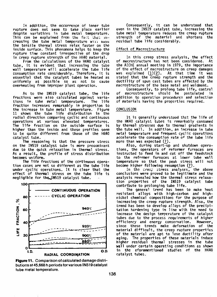
As to the IN519 catalyst tube, the lifefractions were also calculated against varia-tions in tube metal temperature. The lifefraction increases remarkably in proportion tothe increase in tube metal temperature. Figure11 shows the tube life distribution in theradial direction comparing cyclic and continuousoperations at various elevated temperatures.The life fraction on the outside surface ishigher than the inside and these profi les seemto be quite different from those of the HK40catalyst tube.
The reasoning is that the pressure stresson the IN519 catalyst tube is more preaominantdue to the quick relaxation in thermal stress.As a result, the profile of stress distributionbecomes uniform.
The life fractions of the ccntinuous opera-tion cases are not so different as the tube lifeunder cyclic operations. It is clear that theeffect of thermal stress on the tube life isnegligible for theJN519 catalyst tube.
100
80\s0
O 60
U
(f 40
UJIL
-i 20
CONTINUOUS OPERATIONCYCLIC OPERATION
940 r
l. D.RADIAL COORDIHATION
O. D.
Figure 11. Comparison of calculated damage distri-butions at 45,668 h periods for various IN519catalysttube metal temperature.
Consequently, i t can be understood thateven in the IN519 catalyst tube, increasing thetube metal temperature reduces the creep rupturestrength of the materi?! and shortens theresidual tube life considerably.
Effect of Macrostructure
In this creep stress analysis, the effectof macrostructure has not been considered. Atthe AIChE annual meeting in 1979, the importanceof the effect of macrostructure on creep damageswas explained (l.)(2_). At that time i t wasstated that the creep rupture strength and theductility of spun cast tubes are affected by themacrostructure of the base metal and weidinent.
Consequently, to prolong tube life, controlof macrostructure should be postulated inaddition to operation procedures and selectionof material s having the properties required.
CONCLUSION
It is generally understood thet the life ofthe HK40 catalyst tubes is remarkably consumedby thermal stresses due to thermal gradients inthe tube wall. In addition, an increase in tubemetal temperature and frequent cyclic operationsaccelerate the consumption rate of the tube lifemore than was expected (7).
Also, during start-up and shutdown opera-tions, the operators of reformer furnaces areinstructed to feed in and cut off the feedstockto the reformer f urnaces at lower tube walltemperature so that the peak stress wil'l riotbecome higher following resumption (7 ).
In the creep stress analyses, the aboveconclusions were proved to be legitimate and theanalysis revealed how the thermal stress relaxa-tion properties of the IN519 catalyst tubecontribute to prolonging tube life.
The genera! trend has been to make heatresistant alloys with high-carbon and high-nickel chemical compositions for the purpose ofincreasing the creep rupture strength. Also, thetrend has been to develop alloys of the precipi-tation harden ing type in line with the need toincrease the design temperature of the catalysttubes due to the process requiremerts of higherefficiency and energy conservation. However,sinee these trends make deformation of thematerial difficult, the creep rupture propertiesof the material are apt to lose ductility afteraging. The properties of these matertals inducehigher residual thermal stresses in the tubewall under certain operating conditions as shownin the aforementioned studies of the HK40catalyst tubes.
136
Consequently, to prolong tube life,improvement of the operation procedures isexpected. Simultaneously, it is necessary thatthe material researcher and the designer ofreformer furnaces make every effort to developand employ heat resistant alloys having highcreep rupture ductility after aging accompaniedwith creep rputure strength.
APPENDIX 1
Assumption for Creep Stress Analysis
The creep stress analyses were carried outunder the following assumptions:
1) The tube life was calculated on the basisof loading both pressure and thermalstresses. The dead weight of catalysttubes and the stresses from bending orexternal forces from the connecting pointsof the catalyst tubes were ignored.
2) Creep deformations on each stress relaxa-tion stage were calculated using a strainhardening hypothesis.
3) The cumulative life fraction was calculatedon the basis of the Robinson linear lifefraction damage rule (8j as follows:
Life Fraction % = \ -TTT-J 0 tr
where, time increment "dt" at some tempera-ture and stress level is divided by stressrupture time "tr" at the above condition.Each of these outcomes are accumulated forthe initial "time "0" to the terminate time"t" for obtaining the life fraction.The fissure is defined as life fractionwhen it reaches 100 percent.
4) No Load Operation; Just after the reformerfurnace is switched from normal to shutdownoperation, steam and hydrogen are circulat-ed after the feedstock is cut off. In thisoperation, the catalyst tubes are exposedto high temperature service with littletemperature difference in the tube wallbecause the reforming reaction does nottake place in the catalyst tubes.Similar circulating operation takes placereversely at start-up operation. Thiscirculating operation is called no loadoperation and assumes that there is notemperature difference in the tube wall.
Also, operation for reducing the oxidizedcatalysts by steam and hydrogen are definedas no load operation.In the creep stress analysis, it wasassumed that no load operations wouldcontinue for 5-hour periods during theshutdown and start-up operations.
5) As it was confirmed that no overheating norirregular operations occurred during theoperation of the catalyst tubes investigat-ed, the tube wall temperature, internalpressure and heat flux were assumed to beconstant in each run of creep stresscalculations.
APPENDIX 2
Cyclic Operation Mechanism on HK40 Catalyst Tube
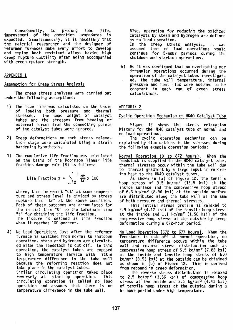
Figure 12 shows the stress relaxationhistory for the HK40 catalyst tube on normal andno load operations.
The cyclic operation mechanism can beexplained by fluctuations in the stresses duringthe following example operation periods:
Normal Operation (0 to 672 hours). When thefeedstock is supplied to the HK40 catalyst tube,thermal stresses occur within the tube wall dueto thermal gradient by a large input in reform-inc heat to the HK40 catalyst tubes.
As shown in (a) of Figure 12, the tensilehoop stress of 9.5 kg/mm2 (13.5 ksi) at theinside surface and the compressive hoop stressof 6.3 kg/mm2 (8.96 ksi) at the outside surfaceare distributed along the tube wall as the sumof both pressure and thermal stresses.
This initial stress profile is relaxed to2.9 kg/mm2 (4.12 ksi) of the tensile hoop stressat the inside and 1.1 kg/mm2 (1.56 ksi) of thecompressive hoop stress at the outside by creepdeformation during a 672-hour period.
No Load Operation (672 to 677 hours). When thefeedstock is cut off at normal operation, notemperature difference occurs within the tubewall and reverse stress distribution such ascompressive hoop stress of 5.5 kg/mm2 (7.82 ksi)at the inside and tensile hoop stress of 6.0kg/mm2 (8.53 ksi) at the outside can be obtainedas shown in (b) of Figure 12. This is derivedfrom rebound in creep deformation.
The reverse stress distribution is relaxedto 2.5 kg/mm2 (3.56 ksi) of compressive hoot»stress at the inside and 3.1 kg/mm2 (4.41 ksi)of tensile hoop stress at the outside during a5- hour period under high temperature.
137
Resumption of Normal Operation (677 to 1.104hours).When the feedstock is supplied again tothe HK40 catalyst tube, new thermal stresses areadded to the relaxed reverse stress profile, anda large new tensile hoop stress of 5.9 kg/mm2(8.39 ksi) at the inside and a compressive hoopstress of 4.0 kg/mm2 (5.69 ksi) at the outsideoccur on the tube wall as shown in (c) of Figure12.
These stress fluctuations continue when thestart-up and shutdown operations are repeated.
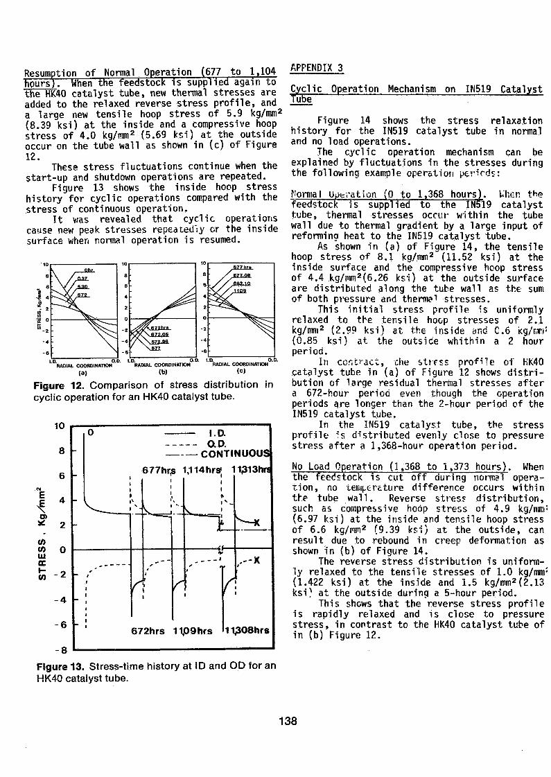
Figure 13 shows the inside hoop stresshistory for cyclic operations compared with thestress of continuous operation.
It was revealed that cyclic operationscause new peak stresses repeatedly or the insidesurface when normal operation is resumed.
''"'RADIAL COORDINATION"""' ''"'RADIAL COORDINATION0'"' ''"RADIAL COORDINATION0'"'(a) (b) (c)
Figure 12. Comparison of stress distribution incyclic operation for an HK40 catalyst tube.
1O
8
6OJ
4 •O>* 2
WW f\o
ccW -2
-4
-6
0 I.D.O.D.
CONTINUOUS
677hr,s 'i
v^____\
m *
'
r
't.1 " -
— »•••«— f
tr
!1
S
1,1 14hrsj '
5
N^Jk— «==i
^t-
- . - — • *
1
•
672hrs 11p9hrs
f
131 3hrs
^— K
,'"X
l
11^08hrs
APPENDIX 3
Cyclic Operation Mechanism on IN519 CatalystTube ".
Figure 14 shows the stress relaxationhistory for the IN519 catalyst tube in normaland no load operations.
The cyclic operation mechanism can beexplained by fluctuations in the stresses duringthe following example operation periods:
Normal opération (0 to 1,368 hours). When t^efeedstock is supplied to theHbl9 catalysttube, thermal stresses occur within the tubewall due to thermal gradient by a large input ofreforming heat to the IN519 catalyst tube.
As shown in (a) of Figure 14, the tensilehoop stress of 8.1 kg/mm2 (11.52 ksi) at theinside surface and the compressive hoop stressof 4.4 kg/mm2(6.26 ksi) at the outside surfaceare distributed along the tube wall as the sumof both pressure and thermal stresses.
This initial stress profile is uniformlyrelaxed to the tensile hoop stresses of 2.1kg/mm2 (2.99 ksi) at the inside and C.6 kg/r,ri!(0.85 ksi) at the outside whithin a 2 hourperiod.
In contract, ehe stress profile of HK40catalyst tube in (a) of Figure 12 shows distri-bution of large residual thermal stresses aftera 672-hour period even though the operationperiods are longer than the 2-hour period of theIN519 catalyst tube.
In the IN519 catalyst tube, the stressprofile -'s distributed evenly close to pressurestress after a 1,368-hour operation period.
No Load Operation (1,368 to 1,373 hours). Whenthe feedstock is cut off during normal opera-tion, no temperature difference occurs withinthe tube wall. Reverse stres? distribution,such as compressive hoop stress of 4.9 kg/mm:(6.97 ksi) at the inside and tensile hoop stressof 6.6 kg/mm2 (9.39 ksi) at the outside, canresult due to rebound in creep deformation asshown in (b) of Figure 14.
The reverse stress distribution is uniform-ly relaxed to the tensile stresses of 1.0 kg/mm:(1.422 ksi) at the inside and 1.5 kg/mm2(2.13ksi; at the outside during a 5-hour period.
This shows that the reverse stress profileis rapidly relaxed and is clos« to pressurestress, in contrast to the HK40 catalyst tube ofin (b) Figure 12.
Figure 13. Stress-time history at ID and OD for anHK40 catalyst tube.
138

Resumption of Normal Operation (1,373 to 7,583hours).When the feedstock is supplied again tothe IN519 catalyst tube, new thermal stress isadded to the relaxed reverse stress profile, anda large new tensile hoop stress of 7.7 kg/mm2(10.95 ksi) at the inside and a compressive hoopstress of 4.0 kg/mm2 (5.69 ksi) at the outsideoccur in the tube wall as shown in (c) of Figure14. However, the initial stress profile israpidly relaxed within a 2 hour period the sameas in the initial start-up operation (1).
Even though these higher stress distribu-tions are repeated at each cyclic operation, itwas found that the thermal stresses at resump-tion are rapidly relaxed and are close to thepressure stress.
Figure 15 shows both the inside and outsidehoop stress histories for cyclic operations, andproves that the pressure stress becomes dominantboth on the inside and outside surfaces incyclic operations for the IN519 catalyst tube.
I.D. O.D. 1.0. D.D. 1 1 5 . S o .RADIAI. COORDINATION RADIAL COORDINATION RADIAL COORDINATION
«a) (W <c)
Figure 14. Comparison of stress distribution incyclic operation for an IN519 catalyst tube.
lU
8
"E e
^ 4o» 4
S 2'(0IUΠnu
(02
4
6
-I.D.Ohr O.D.
-
-
-
•
-
k
\
1p73hrs
^ «*.
1368hrs
7,588hrs
v
ti
45,663 hrs
1A „...
i Itr'I
i
7,583 hrs
^
45,668 hrs
Figure 15. Stress-time history at ID and OD for anIN519 catalyst tube.
LITERATURE CITED
1. T. Kawai, K. Takemura, T. Shibasaki andT. Mohri, Ammonia Plant Safety. 22, 119(1980)
2. T. Kawai, K. Takemura, T. Shibasaki andT. Mohri, Plant Operation Progress, 1 (3),181 (1982)
3. T. Kawai, K. Takemura, T. Shibasaki,L. Rump, B. DanieTsen and J. Wrisberg,"IN519 as Catalyst Tube Material", presentedat the 27th Nat ' l . Meeting, AIChE, LosAngeles (1982)
4. Salot, W. J., Ammonia Plant Safety, 14, 119(1972)
5. Salot, W. J., Ammonia Plant Safety, 15, 1(1973)
6. C. E. Jaske, Hydrocarbon Processing.(1983)
63,
7. T. Kawai and 1. Mohri, "Catalyst Tube No.2",Topsoe-Chiyoda Stream Reformer Symposium,(1977)
8. Robinson, E. L., Transaction of the ASME 74,777 (1952)
9. N. Moriya, T. Kawai and H. Uchida, Bulletinof Arab Federation of Chemical FertilizerProducts, 67, 15 (1981)
KAWAI, T. MOHRI, T.
TAKEMURA, K. SHIBASAKI, T.
139