1974 q skiftoo -...
TRANSCRIPT

1974 / 75 / 76 / 77Q
skiftooTECHNICAL DATAMANUAL
Litho'd in Canada
Trademarks of Bombardier Limited 484 0385 00


D E S C R I P T I O N
I N D E X
PAGE D E S C R I P T I O N PAGE
MODEL IDENTIFICATION. .1
ENGINE TOLERANCESMEASUREMENTS 3
LIST OF ENGINE SECTIONS . .8
247, 302.ENGINE TYPE. . . .9
248, 294 ENGINE TYPE. . . 21
248 ENGINE TYPE(FROM 1975) 29
245 ENGINE TYPE (UP TOSERIAL NO 2762 210). .. . .,41
245, 345 ENGINE TYPE(FROM 1976) 55
305, 338, 343, 401ENGINE TYPE 67
305, 343 ENGINE TYPE(FROM 1976) 75
346, 396, 436ENGINE TYPE 89
346, 436 ENGINE TYPE(FROM 1977) 93
434 440 ENGINE TYPE . . .101
440 ENGINE TYPE(FROM 1976) -109
640 ENGINE TYPE 121
640 ENGINE TYPE(FROM 1976) 129
IGNITION TIMING(TWO CYLINDER ENGINE). . 141
IGNITION" TIMING(ONE BYLINDER ENGINE). . 145
IGNITION TIMING(C.D. IGNITION) 147
. . 149ELECTRICAL CHARTS.
BOMBARDIER IGNITIONTESTER 187
TOOLS 197
- 2
to 7
to 20
to 28'
to 40
to 54
to 66
to 74.'
to 88
to 92
to 100
to 108
to 120
to 128
to' 140
to 144
to 146
to 148
to 186
to 196
to 206
TRACK TENSIONSPECIFICATIONS . . .
TRACK SPECIFICATIONS
DRIVE BELT NUMBER .
DRIVE PULLEYSPECIFICATIONS . . .
DRIVE PULLEYWEAR PADS .
DRIVE PULLEYSPRING TENSION
PULLEY ALIGNMENTSPECIFICATIONS .
SPROCKET AND CHAINSPECIFICATIONS . .
STEERING SYSTEM ... .
SKI SYSTEM
ENGINE TECHNICAL DATA
IGNITION TIMINGSPECIFICATIONS . . .
CARBURETORSPECIFICATIONS . . .
SPARK PLUG, CHART . .
COIL RESISTANCE CHART
207 to 208
209 to 211
212
213 to 216
217
218
219 to 220
221 to 224
225 to 226
227 to 228-
229 to 232
233 to 236
237 to 242
243 to 244
245 to 246

•' '.v~"wi£ --^ '̂<m

SKI-DOO 1977 MODEL SKI-DOO 1976 MODEL.
Elan 250 M 3017Elan 250 T 3018Elan (Europe) 250 M 3019Elan (Europe) 250 T 3020Elan- Stretch(Europe) 250 M 3021Elan Stretch 250 M 3022
Olympique 300 M 3131O.ympique 300 T 3132Olympique 340 3133Olympique 340 E 3134Olympique (Europe), 340 3137Olympique 440 3138
Everest 440 3434Everest 440 E 3435Everest 340 3442Everest 340 E 3443Everest 444 L/C 3444Everest (Europe) 340 3445Everest (Europe) 440 3446
T'NT FA 340 3439T'NT FA 440 3440RV 340 3441T'NT FC 440 3447
Cross Country 340 LC 3559Blizzard 440 LC 3560Blizzard X 254 3560-01Blizzard X 354 3560-02Blizzard X 454 3560-03
Alpine 640 ER 3313Alpine (Europe) 640 ER 3314
Elan 250 3013Elan 250 T 3014Elan 250 M 3015Elan Europe 250 M 3016
Olympique 300 3122Olympique 300 T 3123Olympique 300 T E 3124Olympique 340 3125Olympique 340 E 3126Olympique 440 3127Olympique Europe 300 3128Olympique Europe 300 T 3129Olympique Europe 340 3130
T'NT FC 340 3428T'NT FC 340 E 3429
Everest 440 3430Everest 440 E 3431Everest LC 3436
RV 250 3432RV 340 3433'
Alpine 640 ER 3311Alpine Europe 640 ER 3312
Alpine (White) 640 ER 3315

SKI-DOO 1975 MODEL SKI-DOO 1974 MODEL
Elan 250Elan 250 TElan 300
Olympique 300Olympique 300E•Olympique 340Olympique 340E
TNT E.G. 340'TNT E.G. 340ETNT E.G. .-440TNT E.G. 440E
Everest 440Everest 440E
TNT F.A. 340TNT E.A. 440
Alpine 640 ER(1st run)Alpine 640 ER(2nd run)Alpine 640 ER(3rd run)Alpine 640 ER(4th run)
Stock Racer 245
301030113012
3112311331193120
3418341934203421
34'223423
34263427
3307
3308
3309
3310
3554
Elan 250 -Elan 250 EElan 250 TElan 250 DeluxeElan 294 SS
Olympique 300Olympique 340Olympique 340 SOlympique 340 EOlympique 340 ESOlympique 400Olympique 400 SOlympique 400 EOlympique 400 ESOlympique 440Olympique 440 S
TNT 295TNT 340TNT 340 ETNT 440TNT 440 ETNT 440 Everest
TNT E.A. 340TNT F.A. 400TNT F.A. 440
Nordic 640 ER
30053006300730083009
41013107-093117310831183104-1031143105311531063116
340934043405340634073408
341434153416
3205
Alpine 440 ERAlpine 640 ER
Elite 440 ER
33043305
3701

SECTION 04SUB-SECTION 01 (ENGINE TOLERANCES MEASUREMENT)
ENGINE TOLERANCES MEASUREMENT
CYLINDER TAPER
Maximum: 0.08 mm (.003")Compare cylinder diameter 16 mm (5/8") from top ofcylinder with down to just below the intake port.
On rotary valve engines, measure just below auxiliarytransfer port, facing exhaust port. If the difference ex-ceeds 0.08 mm (.003") the cylinder should be reboredand honed or should be replaced.
Below theintake port
16 mmIrom top
CYLINDER OUT OF ROUND
Maximum: 0.05 mm (.002")Measuring 16 mm (5/8") from top of cylinder with a cyl-inder gauge, check if the cylinder out of round is morethan 0.05 mm (.002"}. If larger, cylinder should be re-bored and honed or should be replaced.
Gudgeonpin
direction
TMeasures tobe compared

SECTION 04SUB-SECTION 01 (ENGINE TOLERANCES MEASUREMENT)
Accurate measurementTo determine piston to wall clearance, the piston shouldbe measured 8 mm (5/16") above its bottom edge andthe cylinder should be measured 16 mm [5/8") below itstop edge.
8 mm
16 mm
The difference between these two measurementsshould be within specified tolerance.
Quick measurementPlace cylinder upside down on a work-bench and pressa feeler gauge against the cylinder wall (intake side)while trying to insert the piston without any ring in itsusual position.
Piston
Long feeler gauge
The thickest possible to use feeler gauge will determinethe piston to wall clearance.
RING END GAP
Position ring half way between transfer ports and intakeport. On rotary valve engines, position ring just belowtransfer ports.
NOTE: In order to correctly position the ring in thecylinder, use piston as a pusher.
Using a feeler gauge, check ring end gap. If gap ex-ceeds specified tolerance the ring should be replaced.
Transfer port
PISTON RING/GROOVE CLEARANCEMaximum: 0.20 mm (.008")Using a feeler gauge check clearance between rectan-gular ring and groove. If clearance exceeds 0.20 mm(.008"), replace piston.

SECTION 04SUB-SECTION 01i (ENGINE TOLERANCES MEASUREMENT)
CRANKSHAFT DEFLECTION
Maximum: 0.06 mm (.0024")With ihfi crankshaft positioned between a center lathe,install a dial indicator as close as possible to crankshaftblade then measure deflection on each side. If deflec-tion exceeds 0.06 mm [.0024") the crankshaft should berepaired by a specialized shop or it should be replaced.
CONNECTING ROD ALIGNMENT
Check if connecting rod is bent as follows:- Once engine crankcase is assembled with the piston
mounted on connecting rod without its piston rings,position cylinder on piston.
NOTE: The cylinder/crankcase gasket must notbe installed.
Rotate crankshaft slowly and at the same time ob-serve piston movement within the cylinder. If pistonbear against one side (PTO or mag. side), the con-necting rod is bent.
o
CONNECTING ROD BIG ENDAXIAL PLAYMaximum: 0.5 mm (.020")
Using a feeler gauge measure distance between con-necting rod and thrusT washer. If axial play exceeds'0.5mm (.020"), the crankshaft should be replaced.
Equal distancein gudgeon
— pin direction
To correct, position needle bearing and gudgeon pinon connecting rod then pry connecting rod as illus-trated.

SECTION 04SUB-SECTION 01 {ENGINE TOLERANCES! MEASUREMENT)
CRANKSHAFT END-PLAY
Maximum: 0.10 mm (.004")
O NOTE: Crankshaft end-play is adjusted only whencrankshaft and/or crankcase is replaced.
Measuringdistancebetween
crankshaftblades
One cylinder engine (247)Maximum crankshaft end-play should be 0.10 mm(.004"). To determine necessary correction:
a) Measure crankcase. To do this first measure eachhalf from mating surface to bottom of bearing seat.Add measurements of both halves then add 0.15 mm(.006") for gasket displacement. Equals A.
Bearing seat
c) Subtract measurement B from measurement Aminus tolerance of 0.10 mm (.004") maximum. Totalbalance is distance to be shimmed. Shim(s) must belocated between magneto side bearing andcrankshaft blade.
b) Measure thickness of each ball bearing. Measure dis-tance between crankshaft blades. Add measure-ments. Total equals B.
Measuringthickness ofbail bearing
Crankshaft end-ptay (0.1- mm (.004") maximum) is ad-justed with a shim(s) located between crankshaft andmagneto side bearing, To determine correct amount ofshims, proceed as follows.
Remove magneto side bearing(s) and existing shim(s).Slide the appropriate bearing simulator and retainingwashers onto the crankshaft.

SECTION 04SUB-SECTION Or (ENGINE TOLERANCES MEASUREMENT)
Position crankshaft assembly into crankcase lower half,making sure that retaining washers are correctly seatedinto the grooves.
Gently tap crankshaft mag. side blade until P.T.O. sidebearing bears against retaining washer.
P.T.O. sirioretainingwasher
Any free-play between the bearing simulator and mag-neto side retaining washer, minus 0.1 mm {,004") max-imum end-play is the distance to be covered by shim(s).Shims are available in variable thickness according toengine type.
Bearingsimulator
Retainingwashet
r

SECTION 04SUB-SECTION 01-02 (ENGINES)
LiST OF ENGINE SECTIONS
247, 302
248,254
248 (FROM 1975)
245 (UP TO SERIAL NO. 2 762 210)
245, 345 (FROM 1976}
305,338,343401
305, 343 (FROM 1976)
346,396, 436
346, 436 (FROM 1977)
434, 4^0
440 (FROM,1976)
640
640 (FROM 1976)

SECTION 04SUB-SECHON 01 fONE CYLINDER ENGINE}
247,302 ENGINE TYPE
247 MUFFLER & SUPPORT
1. Carriage boll2. Threaded spacer3. Insulator rubber4. Support5. WasherG. Nut7. Boll8. Brackei9. Nut
10. Air duct11. Hubher spacer12. Washer
13. Screw14. Nut15. Lockwasher16. Stud17. Distance sleeve18. Muffler19. Exhaust qrommol20. Nut21. Retainer washer22. Rubber washer23. Lockwasher24. Nut

SUHECTtO* 01 (ONE CYUNDER ENGINE)
7. Carnage bolt2. Stopper3. Washer4. Spacer5. Rubber mount (lower)6. Vibration absorber7. Engine support8. Rubber mount (upper)9. Nut
10. Nut11. Lockwasher12. Distance sleeve14. Rubber mount15. Washer16. Boll
17. Muff!er18. Elbow19. Ring20. Spring21. Exhaust manifold22. Spring23. Washer24. Nut25. Bolt26. Rubber spacer27. Mutllor support28. Clamp29. Lockwasher30. Scrow31. dip32. Locking tab33. Nut
10

SECTION 04SUB-SECTION 01 (ONE CYLINDER ENGINE*
MUFFLER & SUPPORT
247 TYPE
REMOVAL FROM VEHICLE
Remove or disconnect the following then lift enginefrom vehicle.
• Pulley guard.
• Drive belt.
• Muffler.
• Chnknknob.
• Decompressor (if applicable).
• Throttle cable.
• Fuel lines.• Elnotrioal connector,
CAUTION: On electric start model, disconnect ne-gative cable (ground) from battery post beforedisconnecting other wires.
• Separate steering column support at upper column.
• Engine mount nuts.
DISASSEMBLY & ASSEMBLY
©Torque to 3.2 kg-m (23 ft-Ibs).
©Torque to 3.6 kg-m (26 ft-Ibs).
©Torque to 2.2 kg-m [16 ftlbsl.
INSTALLATION ON VEHICLE
To install engine on vehicle, inverse removal procedure.However, pay attention to the following.
• Check ignition timing prior to installation in vehicle.
• Check tightness of engine mount nuts, and drivepulley bolt.
• After throttle cable installation, check carburetormaximum throttle opening.
• Check pulley alignment.
302 TYPE
REMOVAL FROM VEHICLE
Remove or disconnect the following then lift enginefrom vehicle.
• Pulley guard.
• Drive belt.
• Air silencer box.
» Throttle cable.
• Fuel lines.
• Muffler.
• Electrical connector.
• Engine mount nuts.
DISASSEMBLY & ASSEMBLY
©Torqueto3.6kg-m (26ft-lbs).
©Torque to 2.2 kg-m [16ft-lbsJ.
INSTALLATION
To install engine on vehicle, inverse removal procedure.However, pay attention to the following.
• Check ignition timing prior to installation in vehicle.
• Check tightness of engine mount nuts, and drivepulley bolt.
• After throttle cable installation, check carburetormaximum throttle opening.
• Check pulley alignment.
11

SECTION 04
©—16 BOTTOM END
1. Crankcase half (P. T.O. side)2. Crankcase half (Mag side)3. Crankshaft4. Polyamid ring5. Bearing6. Shim7. Dowel tube8. Wires grommet9. Stud
JO. Gasket/ / . OH seal12. Bolt or nut13. Lockwasher74. Stud (cylinder)15. Washer (head)16. Nut (head)17. Distance sleeve18. Stud19. Lockwasher20. Nut
22
21. Labyrinth ring (fan!22. Screw23. Shim24. Spring25. Breaker point cam26. Nut27. Locilte iock'n Seal (no 242)28. Needle hearing29. Woodruff key
12

SECTION 04SUB-SECTION 01 {ONE CYLINDER ENGINE}
BOTTOM END
CLEANING
Discard all oil seals and gaskets.
Clean all metal components in a non-ferrous metalcleaner.
DISASSEMBLY & ASSEMBLY
General
Refer to Technical Data Section for component f i t tedlolornnnn nnrl wonr limit.1 If nncusiinry, inf tM to DrivePulley Section to remove drive pulloy.
0©When disassembling / assembling crankcasehalves, do not use heat the crankcase. If heat is neces-sary, temperature must not exceed 55° C(130° F).
(3)@ Crankshaft end-play should he between 0.10-0.40mm (.004-.016"). To determine necnssary correct ion;
a) Measure crankcase. To do this first measure eachhalf from mating surface to bottom of bearing seat.Add measurements of both halves then add 0.15 mm(.006") for gasket displacement. Equals A.
bl Measure thickness of each ball bearing. Measure dis-tance between crankshaft blades. Add measure-ments. Total equals B.
Measuringthickness ofbail bearing
Measuringfiistfincobetweencrankshaftblades
cl Subtract measurement B from measurement A minustolerance of 0.10-0.40 mm t.004"-.016"). Total bal-ance is distance to be shimed. Shim(s) must be lo-cated between magneto side bearing and crankshaftblade.
O NOTE: Crankshaft end-play is adjusted only whencrankshaft and / or crankcase is replaced.
©Do not remove unless necessary.
To remove, heat slightly with a butane torch then pryout using a screwdriver.
To install, apply oil on outside diameter then use asuitable pusher.
Chamfertowardsinside
of crankcase;
13

SECTION 04CYUNDEB EWG1NEJ
©To remove bearing from crankshaft use a protectivecap and special puller as illustrated. (See Tool Section).
Protective o<if)
o NOTE: Prior to magneto side bearing installation,install required shim(s) (crankshaft end play) oncrankshaft extension. At assembly, place bearingsinto an oil container and heat the oil to 100° C(210° F) for 5 to 10 min. This will expand thebearings and permit them to slide easily on theshaft.
©To remove or install new seal into crankcase use anappropriate oil seal pusher as illustrated. (.See ToolSection).
Also, prior to crankcase adjoining, install a protectorsleeve on each crankshaft extension to prevent oil sealdamage (See Tool Section). Apply a light coat of lithiumgrease on seal lip. Seal outer surface should be flushwith 'crankcase.© Ai assembly, torque to 2.2 kg-rn (16 fi-lbs) followingillustrated sequence.
©Torque to 3.6 kg-m (26ft-lbs).
®To remove or install magneto retaining nut, lockcrankshaft in position with special hold-on support.(SeeTool Section). .
At assembly apply Loctite Lock'n Seal 242 on threadsthen torque retaining nut to 7.5 kg-m (54 fT-lbs).
@ Clean thoroughly then apply Loctite Lock'n Sealno. 242 or equivalent.
14

SECTION 0*SUB-ACTION 01 {ONE CYUN0E8 ENGTO
22
/. Ring .2. Piston3. Gudgeon pin4. Circlip5. Cylinder6. Cylinder head7. Gasket (head / cylinder)8. Gasket (cylinder / crankcasei9. Stud
10. Gasket11. Isolating flange12. Locking tab13. Nut14. Exhaust gasket15. Locking tab (Olympiquel16. Nut17. Muffler18. Flat washer19. Nut (head)
TOP END
247ONLY
20. Locking sleeve21. Decompressor22. Cable •23. Switch housing24. Cap nut25. Knob26. Spring plate27. Spring plate reinforcement28. Spring lock29. Lockwasher30. Screw
15

SECTION W{QNECYUNDgMNGKl
TOP END
CLEANING
in a non-ferrous metal
Discard all gaskets.
Clean all metal componentscleaner.
Scrape off carbon formation from cylinder exhaust port,cylinder head and piston dome using a wooden spatula.
O NOTE: The letter "AUS" (over an arrow on thepiston dome) must be visible after cleaning.
Clean the piston ring grooves with a groove cleanertool,or with a piece of broken ring.
DISASSEMBLY & ASSEMBLY
O NOTE: Refer to Technical Data for componentfitted tolerance and wear limit.
©©© Place a clean cloth over crankcase to preventcirclip from falling into crankcase. Use a pointed tool toremove circlips from piston.
V CAUTION: When tapping out gudgeon pins, holdpiston firmly in place to eliminate the possibilities,of transmitting shock and pressure to the con-necting rod.
At assembly, place the piston over the connecting 'rodwith the letters "AUS" (over an arrow on the pistondome) facing in direction of the exhaust port.
O NOTE: Once the circlips are installed turn eachcirclip so the circlip break is not directly on pistonnotch. Remove any burrs on piston causedthrough circlip installation with very fine emerycloth.
Circlip break
Pision notch
®® Position cylinder head on cylinder with fins in linewith crankshaft center line. Cross torque retaining nutto 1.9-2.2 kg-m (14-16ft-Ibs.)
©Tab washer should be replaced if bent more thanthree (3) times. If in doubt, replace.
®At assembly, torque to 2.2 kg-m (16 ft-lbs).
EXHAUST
16

SECTION 01SUB-SECTON01 (ONE CYLINDER ENGINE)
MAGNETO
16
1. Sparkplug2. Protector3. Prelection cap4. H. T. cable5. Screw6. Ground connector7. Ignition coil8. Junction block bracket9. Screw
10, Centrifugal weigh:11. Return spring
12. Magneto housing13. Stud14. Fan15. Lockwasher16. Nut.17. Screw18. Lockwasher19. Magneto ring20. Armature plate21. Screw22. Lockwasher
23. Flat washer24. Condenser25. Ignition generator coil26. Distance sleeve27. Brake-light coil28. Screw29. Lighting coil30. Lubricating wick31. Breaker point set ass'y32. Pivot pin33. Breaker point set
17

SECTION 04SUB-SECT1ON01 {ONE CYUWDER ENGINE}
MAGNETO
CLEANING
Clean all metal components in a non-ferrous metalcleaner.
CAUTION: Clean armature using only a cleancloth.
DISASSEMBLY & ASSEMBLY
© At assembly, apply a small amount of grease intospring seating.©With rnngnoto retaining nut removed and hold-onsupport in plnoo, install special puller onto hub.
Tighten puller nut at same time, tap on nut head using.a hammer to release magneto from its taper.
At assembly, clean crankshaft extension (taper) thenapply l.ochto Lock'n Seal 242, position magneto oncr.'inkshalt with the knywny and the cam notch positionas illustrated.Apply Loclito Lock'n Seal 242 on threads of retaininghut then torque to 7.5 kg m (54 f t - lbs) .
©Apply Loctlte Lock'n Seal 242 on threads.
©To replace a capacitor, it is first necessary to discon-nect the two (2! black leads using a soldering iron. Theoapacitor can then bo driven out of the armature plateusing a suitable dnft. To reinstall, inverse procedure.
@@@Whenever a1 coil is replaced, the air gap [dis-tance between magnol and coil end) must be adjusted.
To check air gap, insert a fouler gauge of 0.25-0.38 mm(.010"-.015") between magnet and coil ends. If neces-sary to adjust, slacken retaining screws and relocatecoil.
(Si) When lOplnoing bn.Mknt [mini sf;:of gronso on lubricating wick.© Do not remove pivot pin unless replacement isneeded, if removed reinstall with Lootite Lock'n Seal onthreads.
Old type breaker point sol c.sn bo replaced by new typeif pivot pin is nimovod. 'Whon installing new breakerpoint type it is advisable to lill tin; pivot pin cavity ol thenrmnture plate with t.nr:iite 2 /7 (thick red solution).
18

SECTION <W-SECTION mm CYUNOER ENGINE
COOLING SYSTEM12 10
MANUAL START ENGINE
26 25
ELECTRIC START ENGINE
1. Fan cowl ass'y2. Fan cowl stud (4)3. Spring bracket4. Labyrinth ring (manualstar! only)5. Screw (4)6. Screw7. Ground cable8. Cable clamp9. Flat head screw
10. Spring washer
11 Nm12. Air deflector13. Fan cowl cover14. Fan cowl15. Lock washer16. Cylindrical head screw (2)17V Dowelscrew 12}18. Allen screw (4!19. Cylindrical head screw (long)20. Starter stud
21. Lock washer (4)22. Magneto ring23. Fan ass 'y24. Starter ring gear25. Lock washer (8>26. Hex. cap screw (8)27. Stud28. Lock washer (4)29. Nut (4)30. Spring retainer
19

SUa-SECTtONOI (QPig CYLINDER ENGINE)
COOLING SYSTEM
CLEANING
Clean all metal components in a non-ferrous metalcleaner.
CAUTION: Clean armature using only a cleancloth.
DISASSEMBLY & ASSEMBLY
©At assembly, position labyrinth ring with bevelledside on top.
@® @@ To remove fan cowl ass'y and / or magnetofrom electric start engine, it is first necessary to separatefan cowl cover from fan cowl.
To remove magneto ring / fan ass'y from engine, lockcrankshaft in position w'th special hold-on support. Re-move magneto retaining nut, then install special pulleronto hub (See Tool Section).
Tighten puller nut and at same tine, tap on nut headwith a hammer to release magneto from its taper. Atassembly, torque retaining nut to 7.5 kg-m (54 ft-lbs.)
Hold-on support
©®@®At assembly, apply Loctite "Lock'n242" on screws threads.
Seal
NOTE: It should be noted that to correctly removea Loctite locked screw, it is first necessary to tapon head of screw to break Loctite bond. This willeliminate the possibility of screw breakage.
20

SECTION 04SUB-SECTION 02 {TWO CYLINDER
248.294 ENGIIMt
BOTTOM END
-20-
248TYPE
10
21

SECTION 04SUB-SECTION Q2 {TWO CYilNDER ENGINE)
BOTTOM END
1. Crankshaft2. "0"r!ng (4 or 6)3. Woodruff key
4. Needle bearing5. Ball bearing (2 or 3)6. Retaining disc7. Distance sleeve (6 mm • .232")8. Distance sleeve 112 mm - .0472")9. Oil seal (P.T.O.}
10. Distance sleeve (17.7 mm -.697")1 L Distance sleeve (9.7mm • .382")12. Shim(s)13. Oil seal (Mag)14. Lock washer
15. Magneto retaining nut16. Labyrinth sealing ring17. Crankcase lower half18. Dowel pin19. Crankcase upper half20. Cylinder stud21. Crankcase stud (294 only) (2}22. Crankcase stud (8)23. Crankcase stud 12)24. Clamp25. Cap26. Spring washer 18 or 10)27. Lock washer (8 or 10}28. Nut (8 or 10)
TOP END
29. Lock washer (2)30. Nut (2)31. Spacer {4, if applicable)32. Stud 14)33. Lock washer 14)34. Nut 14)35. Capacitor {2)36. Screw (2)37. Nut (2)38. Ignition coil39. Lock washer (6!40. Screw (6141. Ignition box cover42. Screw
PistonGudgeon pinCirciipRectangular ringL-Trapeze ringCylinder/crankcase gasket
•Cylinder (P.T.O. side)Cylinder (Mag. side)Cylinder head gasketCylinder head (P. T.O. side)Cylinder head (Mag. side}Plain washerNut (12 or 14)Distance nutSupporting sleeveDistance nutExhaust manifold gaskerExhaust manifoldSealing ringLock washer 14}Allen screw (4)Stud (4)Intake manifold gasketIsolating flangeRubber ringIntake manifoldLock washerStudCarburetor flange gasketTab lock
22

SECTION 04SUB-SECTION 02 (TWO CYUNDER ENGINE)
MAGNETO
13
1. Nut (3)2. Lock washer. (3)3. Starting pulley4. Stud 13)5. Magneto housing
6. Magneto ring7. Screw (3}8. Screw 14)9. Spring washer (4)
10. Brake light coil
11. Spacer12. Ignition generator
coil13. Armature plate14. Lighting coil
15. Pivot pin16. Breaker point set17. Bolt18. Lock washer19. Nut
20. Washer21. Screw22. Washer23. Retaining clip
1. Cylinder cowl2. A lien screw3. Elastic stop nut (3)4. Stud (2)5. Washer {216. Bolt
7. Lock washer8. Cowl retainer washer9. Spring washer
10. Allen screw11. Fan shaft12. Woodruff key
13. Ball bearing14. Shim (1 mm/,040"}15. Locking ring16. Shim (as required)17. Pulley half18. Fan
19.20.21.22.23.
Lock washerFan nutFan housingLock washer (4)Screw
24. Screw (2}
25. Stud26. Nut27. Junction block
bracket28. Fan belt29. Fan cover
23

SECTION 04SUB-SECTION 02 (TWO CYLINDER ENGINE)
REMOVAL
Remove or disconnect the following, then lift engine fromvehicle.
Front-mounted engine• Drive belt• Muffler• Rewind starter• Air silencer• Choke cable• Throttle cable• Fuel lines at carburetor
Note: Secure fuel lines to steering support so that theopened ends are higher than the fuel tank.
• Electrical connector• Engine mount nuts
Center mounted engine
Drive beltMufflerChoke knobThrottle cableFuel linesElectrical connectorsSteering column support at upper columnEngine mount nuts
DISASSEMBLY & ASSEMBLY
If necessary, remove drive pulley as described in drive pul-ley section.
Note: Refer to Technical Data Section for component fit-ted tolerance and wear limit.
Bottom end©To remove bearing from crankshaft use a protective capand special puller as illustrated. (See Tool Section).
Note: Prior to magneto side bearing installation, determinecrankshaft end-play and install required shim (s) on crank-shaft extension.
At assembly, place bearings into an oil container and heatthe oil to 200° F. for 5 to 10 min. This will expand thebearings and permit them to slide easily on the shaft. Installbearings with groove outward.
©Crankshaft end-play js adjusted with a shim(s) locatedbetween crankshaft and magneto side bearing. To deter-mine correct amount of shim, proceed as follows.
Remove magneto side bearing and existing shim(s). Slidethe appropriate crankshaft ring and retaining disc onto thecrankshaft. (See Tool Section).
Position crankshaft assembly into crankcase lower half,making sure that retaining discs are correctly seated intothe grooves.
Gently tap crankshaft until P.T.O. side bearing bears againstretaining disc.
Any free-play between the crankshaft ring and magnetoside retaining disc, minus recommended end-play, is thedistance to be covered by shim(s). Shims are available inthickness of 0.1 mm/.004", 0.2 mm/.008", 0.3 mm/.012" ,0.5 mm/.020", 1 mm/.039".
Note: Crankshaft end-play is adjusted only when crank-shaft and/or crankcase is replaced.
@To remove or install magneto retaining nut, lock crank-shaft in position with special hold-on support as illustrated.(See Tool Section).
Flywheel
hold-on
support
24

SECTION 04SUB-SECTION 02 (TWO CYLINDER ENGINE)
At assembly torque retaining nut to 42-50 ft-lb.
©To increase sealing between left and right crankcasehalves, on engine equipped with an external labyrinth seal,a steel ring is available, (part no. 414-2072}.
Prior to installation, the steel ring must be stretched open.To do this, slide the ring onto the neck of a soft drinkbottle (2 1/2" outside diameter).Install steel ring on crankshaft labyrinth as illustrated.
steel ring
@ @ @ Crankcase halves are factory matched and there-fore, are not interchangeable or available as single halves.
Prior to joining of crankcase halves, apply a light coat of"Loctite" crankcase sealant to mating surfaces of bottomhalf. Position spring washers, lock washers and nuts oncrankcase studs then torque nuts to 14-16 ft-lb followingillustrated sequence.
nNote: Torque the two smaller nuts on magneto side to 9ft-lb'.@At assembly torque crankcase/support nut to 23-29 ft.-lb.
Top end
©©©Place a clean cloth over crankcase to prevent cir-clip from falling into crankcase. Use a pointed tool to re-
move circlip from piston.
Drive the gudgeon pins in or out using a suitable drivepunch and hammer.
Caution: When tapping gudgeon pin in or out of piston,hold piston firmly in place to eliminate the possibilities oftransmitting shock and pressure to the connecting rod.
At assembly, place the pistons over the connecting rodswith the letters "AUS", over an arrow on the piston dome,facing in direction of the exhaust port.
EXHAUST
Note: Once circlips are installed, turn each circlip 'so thatthe circlip break is not directly on piston notch. Removeany burrs on piston caused through circlip installation withvery fine emery cloth.
Circlip break
Piston notch
®©To insure correct cylinder alignment, install and se-cure intake and exhaust manifolds on cylinder prior tocylinder head tightening. Cross torque cylinder head nuts to14-16 ft-lb.
Note: Torque each head individually.
@ At assembly, torque to 14-16 ft-lb.
Magneto
0 At assembly torque to 9 ft-lb.
0® ©With magneto retaining nut removed and hold-on
Flywheel puller
25

SECTION 04SUB-SECTION 02 (TWO CYLINDER ENGINE)
support in place, install special puller onto hub. Tightenpuller bolt and at same time, tap bolt head using a hammerto release magneto from its taper. (See Tool Section)
Note: Do not separate magneto housing from magneto ringunless necessary. At assembly, apply Loctite. "Lock'n Seal"on magneto housing hub where magneto ring center boresits.
©©©When a coil is replaced, the air gap between mag-net and armature must be adjusted.
To check air gap insert a feeler of correct thickness (.025mrn/.010"-0.39 mm/.015"} between magnet and eacharmature end.
CHECKING THE AIR GAP
If necessary to adjust, slacken retaining screw and relocatecoil.
©Do not remove pivot pin unless replacement is needed.At assembly, apply Loctite "Lock'n Seal" on threads,
©When replacing breaker point set, apply a light coat ofgrease on pivot pin and rubbing block. Recheck enginetiming.
Cooling system@@@@At assembly, apply Loctite "Lock'n Seal" onthreads to prevent loosening through vibration.
Note: To correctly remove a "Loctite" locked screw, it isnecessary to slightly tap on head of screwdriver to breakbond.
®®©To remove or install bearing, heat bearing housingto 140°~160°F.
©®@®@@ To remove or install fan retaining nut,lock fan in position with fan holder wrench. (See ToolSection!.
Hold-on wrench
At assembly, torque retaining nut to 42-50 ft-lb. Make surethat belt is not squeezed between pulley halves.
Correct fan belt free-play is 1/4". To adjust, add or removeshim(s) between inner and outer pulley halves. Excessshim(s) must be positioned between outer pulley half andfan.
Fan belt alignmentFor reliable fan belt operation, the two fan belt pulleysmust lie within .020" of either side of the pulley centerline.
Prior to checking alignment, check fan belt free-play.
Position and secure aligning too! (See Tool Section) onmagneto housing as illustrated.
.060" ± .020"
IMI*
ALIGNING TOOL

SECTION 0402 (TWO CYLINDER ENGINE*
Turn knurled knob to center bent feeler rod between pulleyhalves. Insert a .040" feeler gauge between tool arm andknurled knobs. If gauge fits between both sides of the arms,the setting lies within tolerance.
If clearance is smaller than .040" on one side, shim{s) mustbe added or removed between bearing and inner pulley halfto bring both gaps within tolerance of .060" ±.020".
Excess shim(s) should be stored between outer pulley halfand fan.
CLEANING
Discard all oil seals, gaskets and "0" rings.
Clean all rnetal components in a non-ferrous metal cleaner.
Caution: Clean armature with a clean cloth only.
Scrape carbon formation from cylinder exhaust ports, cyl-inder heads and piston domes.
Note: The letter "A US" over an arrow on the piston domemust be visible after cleaning.
Clean the piston ring grooves with a groove cleaner tool,and/or a piece of broken ring.-
Remove old sealant from mating surfaces of crankcase witha scraper blade,
Caution: Never use a sharp object to scrape away old seal-ant as score marks incurred are detrimental to crankcasesealing.
INSTALLATION
To install engine on vehicle, inverse removal procedure.However, pay attention to the following:
• Torque engine mount nuts to 18-23 ft-ib.
• After throttle cable installation, check carburetormaximum throttle opening.
• Check pulley alignment.
• Check ignition timing.
27


SfCTlONM
248 ENGINETYPE (FROM 1975)
ENGINE SUPPORT & MUFFLER
18
27 26 25
/. Carriage bolt2. Threaded spacer bushing3. Rubber insulator4. Engine support5. Washer6. Nut7. Bolt8. Engine bracket9. Nut
JO. Air duct11. Rubber spacer12. Washer
73. Screw14. Exhaust manifold15. Aluminum ring16. Muffler17. Spring18. Bolt19. Cup20. Bushing21. Spring22. Cup23. Nut24. Exhaust grommet
25. Clip26. Washer27. Screw28. Plug29. Rubber washer30. Washer31. Screw32. Stud33. Lockwasher34. Nut35. Lockwasher36. Screw
29

SECTION 04SUB-SECTION 02 {TWO CYUN02R ENGINE)
ENGINE SUPPORT & MUFFLER
REMOVAL FROM VEHICLE
Remove or disconnect the following, then lift enginefrom vehicle.
• Pulley guard
• Drive belt
• Muffler
• Choke knob
o Throttle cable
• Fuel lines
• Electrical connectors
• Steering column support at upper column
• Engine mount nuts
DISASSEMBLY & ASSEMBLY
©Torque to 3.2 kg-m (23 ft-lbs).
@)Torque to 3.6 kg-m (26 ft-lbs)
® Torque to 2.2 kg-m (16 ft-lbs)
INSTALLATION
To install engine on vehicle, inverse removal procedure.However, pay attention to the following:
• Torque engine mount nuts to 2.7 kg-m (20 ft-lbs).
• After throttle cable installation, check carburetormaximum throttle opening.
• Check pulley alignment.
30

BOTTOM END
10
19 18
1. Crankshaft2. Shim3. Crankcase lower half4. Crankcase upper half5. Bearing6. Retaining washer7. Oil seal8. "O"ring9. Distance ring 6 mm
10. Distance ring 9.7mm11. Needle cage bearing12. Lockwasher13. Magneto ring nut14. Loctite24215. Woodruff key16. Stud (cylinder)17. Crankcase sealant18. Ignition coil cover
19. Screw20. Spring washer21. Lockwasher22. Bolt or stud with nut23. Bolt or stud with nut24. Bolt or stud with nut25. Stud26. Nut
31

SECTION 04SUB-SECTION 02 (TWO CYLINDER
BOTTOM END
CLEANING
Discard all oil seals gaskets and "0" rings. Clean allmetal components in a non-ferrous metal cleaner.
Remove old sealant from crankcase mating surfaceswith Bombardier sealant stripper.
CAUTION: Never use a sharp object to scrapeaway old sealant as score marks incurred are detri-mental to crankcase sealing.
DISASSEMBLY & ASSEMBLY
General
Refer to Technical Data Section for component fittedtolerance and wear limit. If necessary, refer to Drive Pul-ley Section to remove drive pulley.
©©Crankshaft end-play is adjusted with a.shimfs)located between crankshaft and magneto side bearing.To determine correct amount of shim, proceed asfollows.
O NOTE: Crankshaft end-play is adjusted only whencrankshaft and / or crankcase is replaced.
Remove magneto side bearing and existing shim(s).Slide the appropriate bearing simulator and retainingwasher onto the crankshaft. (See Tools Section).
Position crankshaft assembly into crankcase lower half,making sure that retaining washers are correctly seatedinto the grooves.Gently tap crankshaft until P.T.O. side bearing bearsagainst retaining washer.
Any free-play between the bearing simulator and mag-neto side retaining washer, minus recommended end-play, is the distance to be covered by shim(s). Shims areavailable in thickness of 0.1 mm (.004"), 0.2mm (.008"),0.3 mm (.012"), 0.5mm (.020"), 1mm (.039").
Bearingsimulator
©©©Crankcase halves are factory matched andtherefore, are not interchangeable or available singlehalves.
Prior to joining of crankcase halves, prepare mating sur-faces with crankcase sealant primer then apply a lightcoat of crankcase sealant (See Tool Section) as perinstruction printed on container.
Position the crankcase halves together and tighten nuts(or. bolts) by hand then install armature plate (tighten)on magneto side to correctly aiign the crankcase halves.
Torque nuts (or bolts) to 2.2 kg-m (15 ft-lbs) followingillustrated sequence.
O NOTE: Torque the two smaller nuts on magnetoside (no. 11 and 12) to 1.2 kg-m (9ft-lbs).
®To remove bearing from crankshaft use a protectivecap and special puller as illustrated. (See Too! Section).
O NOTE: Prior to magneto side bearing installation,determine crankshaft end-play and install requiredshim(s) on crankshaft extension.
32

SECTION 04SUB-SECTION 02 (TWG.CYUttDEff £N<*JN£)
At assembly, place bearings into an oil container andheat the oil to 100° C (210° F) for 5 to 10 min. This willexpand the bearings and permit them to slide easily onthe shaft. Install bearings with groove outward.
©At assembly apply a light coat of lithium grease onseal lips then position oil seal with outer surface flushwith crankcase.
®To remove or install magneto retaining nut, lockcrankshaft in position with special hold-on support asillustrated. (SeeTool Section).
Flywheelhold-onsupport
At assembly torque retaining nut to 6.4 kg-m (46 ft-lbs),
(§(§) Torque to 2.2 kg-m (16 ft-lbs).
® Torque to 1.2 kg~m (9 ft-lbs).
@ Torque to 3.6 kg-m (26 ft-ibs).
33

SECTTOW
TOP END
27
1. Gasket (cylinder/crankcase)2. Cylinder(P.T.O.)3. Cylinder (MAG)4. Cylinder head gasket5. Cylinder head (PTO)6. Cylinder head (MAG)7. Flat washer8. Nut (head)9. Support sleeve
10. Distance nut11. Distance nut
12. Stud13. Gasket14. Isolating flange15. Rubber ring16. Intake manifold17. Lockwasher18. Nut19. Stud20. Gasket21. Locking tab22. Nut
23. Exhaust gasket24. Exhaust manifold25. Lockwdsher26. Allen capscrew27. Sealing ring28. Clip29. "L"ring30. Rectangular ring31. Piston32. Gudgeon pin33. Circlip
34

SECTION 04SUB-SECTION 02 (TWO CYUMDEft ENGINE!
TOP END
CLEANING
Discard all gaskets.
Clean all metal components in a non-ferrous metalcleaner.
Scrape off carbon formation from cylinder exhaust port,cylinder head and piston dome using a wooden spatula.
O NOTE: The letter "AUS" (over an arrow on thepiston dome) must be visible after cleaning.
Clean the piston ring grooves with a groove cleanertool, or with a piece of broken ring.
DISASSEMBLY & ASSEMBLY
NOTE: Refer to Technical Data for componentsfitted tolerance and wear limit.
© ®To insure correct cylinder alignment, install andsecure intake and exhaust manifolds on cylinder priorto cylinder head tightening. Cross torque cylinder headnuts to 2.1 kg-m(15ft-lbs).
® ©©Torque nuts and distance nuts to 2.1 kg-m (15ft-lbs). Correct position for distance nuts is as followingillustration.
O
Distance nut
V CAUTION: When tapping gudgeon pin in or outof piston, hold piston firmly in place to eliminatethe possibilities of transmitting shock and pressureto the connecting rod.
At assembly, place the pistons over the connecting rodswith the letters "AUS" (over an arrow on the pistondome) facing in direction of the exhaust port.
EXHAUST
O NOTE: Once circlips are installed, turn each cir-clip so that the circlip break is not directly onpiston notch. Remove any burrs on piston causedthrough circlip installation with very fine emerycloth.
Circlip break
Piston notch
Torque to 2.1 kg-m (15ft-lbs).
a clean cloth over crankcase to preventcirclip from falling into crankcase. Use apointed tool toremove circlip from piston.
Drive the gudgeon pins in or out using a suitable drivepunch and hammer.
35

SECTION 04SUB-S£CTIONS2(7WO CYUN03* 6NGIN£J
MAGNETO
I NUT2. Lockwasher3. Starting pulley4. Lockwasher5. Nut6. Stud7. Magneto housing8. Locn'te2429. Screw
JO. Magneto ring/1. Armature plate ass'y12. Allen capscrew
13. Flat washer14. Wires grommet15. Coil16. Screw17. Nut18. Condenser with clamp19. Lighting coll20. Distance sleeve21. Lockwasher22. Screw23. Female connector24. Ignition generator coil
25. Lubricating wick26. Breaker point set27. Pivot pin28. Breaker point29. Sparkplug30. Protector31. Protection cap32. Hubberring33. H. r. Cable34. Protection cap35. Brake light coil
36

SECTION 04SUB-SECTIONS (TWO CYLINDER ENGINE}
MAGNETO
CLEANING
Clean all metal components in n non-ferrous metalcleaner.
YV CAUTION: Clean armature ass'y using only aclean cloth.
DISASSEMBLY &ASSSEMBLY
©Torque to 6.4 kg-m (46 ft Ins).
©Torque to 1.2 kg-m (9 fl-ibs)
©®®®To remove or install magneto retaining nut,lock crankshaft in position with special hold-on supportas illustrated. (See Tool Section).
Flywheelhold-onsupport
Prior to magneto installation, clean crankshaftextension(taper) then apply Loctite Lock'n Seal 242.
Install magneto retaining nut with lockwasher then tor-que to 6.4kg-m (46ft-lbs).
®@©Whenever a coil is replaced, the air gap (dis-tance between magnet and coll end) must be adjusted.
Checkingthe air gap
To check air gap, insert a feeler gauge of 0.25-0.39 mm(.010-.015") between magnet and coil ends. If necessaryto adjust, slacken retaining screws and relocate coil.
@Do not remove pivot pin unless replacement isneeded. At assembly, apply Loctite "Lock'n Seal" onthreads.
® @When replacing breaker point set, apply a lightcoat of grease on pivot pin and lubricating wick.
With magneto retaining nut removed and hold-on sup-port in place, install special puller onto hub. Tightenpuller bolt and at same time, tap bolt head using a ham-mer to release magneto from its taper. (See ToolSection).
Flywheel puller
o NOTE; Do not separate magneto housing frommagneto ring unless necessary. At assembly, ap-ply Loctite "Lock'n Seal" on magneto housinghub (where magneto ring center bore sits) and onretaining screws.
37

SECTION 04SU&^eCTJQN 02 (TWO CYUWE* ENGINB
COOLING SYSTEM
©
22
28 (3) 24 23 26 £7) 28 (9
7. Cylinder cowl (intake)2. Cylinder cowl (exhaust)3. Screw4. Nut5. Spring washer6. Screw7. Screw8. Loctfte no, 2429. Fan housing
10. Circtip
11. Shim12. Bearing13. Fan shaft14. Woodruff key15. Shim16. Pulley half17. Shim18. Belt19. Fan20. Locking washer
21. Nut22. Fan cover23. Stud24. Stud25. Junction block bracket26. Lockwasher27. Nut28. Lockwasher29. Screw30. Screw
38

SECTION 04SUB-SECTION02 (TWO CYLINDER ENGINE}
COOLING SYSTEM
CLEANING
Clean all metai components in a non-ferrous metalcleaner.
DISASSEMBLY & ASSEMBLY
©©© ©@® At assembly, apply Loctite Lock'n sealor equivalent on threads to prevent loosening throughvibration.
O NOTE: To correctly remove a "Loctite" lockedscrew, it is necessary to slightly tap on head ofscrewdriver to break bond.
©To remove or install bearing, heat bearing housing to65° C)150° F).
© Fan belt pulleys alignment
For reliable fan belt operation, the two fan belt pulleysmust lie within 0.5 mm (.020") of either side of the pul-ley center line.
Prior to checking alignment, check fan belt free-play.
Position and secure aligning tool (See Tool Section) onmagneto housing as illustrated.
Bent feeler rod
1.5mm ±0.5
Knurledknob
Aligning arm
Turn knurled knob to center bent feeler rod betweenpulley halves. Insert a 1 mm (.040") feeler gauge be-tween tool arm and knurled knobs. If gauge fits betweenboth sides of the arms, the setting lies within tolerance.
If clearance is smaller than 1 mm (.040") on one side,shim(s) must be added or removed between bearing andinner pulley half to bring both gaps within tolerance of1.5mm t 0.5 (.060" i .020".)
Excess shim(s) should be stored between outer pulleyhalf and fan.
©©Correct fan belt free-play is 6mm (% "}. To adjust,add or remove shim(s) (no. 17) between inner and outerpulley halves. Excess shim(s) must be positioned be-tween outer pulley half and fan.
© ® © Newer pulley half does not have a shoulder onits inner face so it is installed with a 6 mm (0.236")spacer.
Pulley half
NEW TYPE OLDTYPE
There are two types of fan interchangeable. The firsttype utilizes two pulley halves and the second typeutilizes one pulley half (the second half being part ofthe fan itself).
To remove or install fan retaining nut, lock fan in posi-tion with fan holder wrench. (See Tool Section).
Hold-on wrench
At assembly, torque retaining nut to 6.4kg-m (46ft-Ibs).Make sure that belt is not squeezed between pulleyhalves.
ALIGNING TOOL
39

if•*•»

tonoN 02 -crwo «t3N$SJi mm®
245ENGINL IYPE
BOTTOM END
1. Crankshaft2. Woodruff key3. Sper (1 mm / .040")4. Ball bearing5. "0"ring6. Retaining disc7. Oil seal8. Lockwasher9. Magneto retaining nut
10. Shim (as required)11. Needle bearing12. Lowercrankcase half13. Upper crankcase half
14. Crankcase stud (8) (57mm)15. Crankcase stud (2) (37mm)16. Dowel pin17. Sealing ring18. Oil inlet nipple19. Cap20. Spring clip21. Valve cover stud (18mm)22. Valve cover stud (25mm)23. Crankcase support stud (4)24- Flat washer (10)25. Lock washer (14)26. Nut (18)27. Lock washer f4)28. Nut (4)29. Drain screw30. Cylinder stud (8)31. Vent elbow32. Rubber cap
33. Rubber grommet34. Junction block bracket35. Lock washer36. Screw37. Horary valve cover38. Plain washer39. "O"ring 'Applies to engine up to serial no 2,762,210
41

SECTION04SU&~S£Cn0WQ2(7W0 CYUNDER ENGINE)
fl-12-fi fl-12-fi
TOP END
7. Piston2. Gudgeon pin3. Cirdip4. L-Trapezring5. Rectangularring6. Cylinder /crankcase gasket7. Cylinder. (P. T. O. side)8. Cylinder {Mag. side)9. Cylinder head gasket
10. Cylinder head11. Plain washer (8)12. Expansion sleeve 18)13. Cylinder head nut (8)14. Exhaust manifold stud (4)15. Exhaust manifold gasket16. Exhaust manifold17. Lock washer (4)18. Nut (4)
3-U
ROTARY VALVE MECHANISM
/. Allen screw2. Washer3. Rotary valve gear4. Rotary valve disc5. Locking ring6. OH seal7. Bali bearing8. Woodruff key9. Rotary valve shaft
10. Distance sleeve11. Rubber "0"ring12. Pinion13. Spring sleeve14. Spring15. Washer (1 mm)16. Locking ring17. Ball bearing18. Locking ring19. End cap
42

SECTION 04SU8-SECTK)NQ2(TWO CYLiNDiR ENGINE
/. Nut (3)2. Lockwahser (3)3. Starting pulley4. Starting pulley stud5. NUT (4)6. Washer (4)7. Magneto housing8. Magneto ring
9
MAGNETO9. Allen screw (41
10. Coil retaining screw (4)11. Lockwasher (6)12. Washer (2)13. Allen screw (2)14. Armature plate ass'y15. Lighting coil16. Capacitor charging coil
REMOVAL
Disconnect or remove the following from vehicle, ifapplicable:
— Drive belt
— Air silencer
— Unscrew slide chamber cover from carburetors thenwithdraw throttle slide ass'y from carburetor,
— Rotary valve mechanism vent tube
— Fuel lines, primer lines and impulse line
— Electrical wires
- Muffler
— Rewind starter
— Engine mount nuts and front air deflector— Drive pulley {as described in Drive Pulley Section).
DISASSEMBLY & ASSEMBLY
Special puller
Prior to installation, place bearings into an oil containerand heat the oil to 93U C (200° F) for 5 to 10 min. Thiswill expand bearing and ease installation.
Install bearings with groove outward.
©To remove or install magneto retaining nut, lockcrankshaft in position with special hold-on support, asillustrated. (SeeTool Section).
At assembly, torque magneto retaining nut to 8.0-8.6kg-m (58-62ft-lbs).
ONOTE; Refer to Technical Data Section for com-ponent fitted tolerance and wear limit.
Bottom End
©To remove bearing from crankshaft, use a protectivecap and special puller as illustrated.
43

SECTION 04SUB-SECTION 02 (TWO CYLINDER
©Whenever the crankshaft and/or the crankcase isreplaced, the crankshaft end-play must be adjusted. Toadjust proceed as follows:
Remove magneto side bearing and existing shims. Re-install magneto side bearing without the shims makingsure bearing sits flush against crankshaft shoulder.
Position crankshaft ass'y into lower crankcase half.Make sure that retaining discs are correctly seated intotheir grooves.
Gently tap crankshaft counterweight unto P.T.O. sidebearing bears against retaining disc.
Any free-play between the magneto side bearing andretaining disc minus recommended end-play is the dis-tance to be covered by shim(s).Shims are available in thickness of 0.15 mm (.006"),0.2mm (.008"), 0.3 mm (.012") and 1.0mm (.039")".
Rijiiiiniiicjdisc
@®@ prior to joining of crankcase halves preparemating surfaces with crankcase sealant primer thenapply a light coat of crankcase sealant as per instruc-tions printed on containers.
Position spring washers, lock washers and nuts oncrankcase studs then torque nuts .to 1.9-2.2 kg-m[14-V6 ft-lbs) following illustrated sequence.
NOTE: There is no spring washer on the last two(2) magneto side studs.
@ At assembly, torque to 1.9-2.2 kg-m (14-16 ft-lbs).
© At assembly, torque to 4.0-4.8 kg-m (29-35 ft-lbs).
©Apply Loctite Lock'n Seal on the threads of the two(2) studs, screwed into the crankcase, above the intakeports.
Top End
©©©Place a clean cloth over crankcase to preventcirclips from falling into crankcase then use a pointedtool to remove circlips from piston.
Drive the gudgeon pins in or out using a suitable drivepunch and hammer.
V CAUTION: When tapping gudgeon pin in or outof piston, hoid piston firmly in place to eliminatethe possibilities of transmitting shock and pressureto the connecting rod.
At assembly, place the pistons over the connectingrods with the letters AUS, over an arrow on the pistondome, facing direction of the exhaust port.
EXHAUST
Once the circlips are installed, turn each circlip so thatthe circlip break is not directly in line with piston notch.Using very fine emery cloth, remove any burrs on pistoncaused through circlip installation.
Circlip break
Piston notch
©@©At assembly, torque to 2.2-2.5 kg-m (16-18ft-lbs) following illustrated sequence.
44

• SECTION 04SUB-SECTION 02ITWO CYLINDER ENGINE)
O .NOTE: To prevent leakage, install exhaust mani-fold prior to cylinder head tightening.
©At assembly, torque to 1.9-2.2 kg-m (14-16ft-1bs).
Rotary Valve Mechanism
©©At assembly, apply Loctite crankcase sealant onrotary valve gear and bearing mating surfaces.
Rotary va!vn gear
Bull Apply Lociite
0To correctly install the rotary valve disc proceed asfollows:
- Bring magneto side piston to Top Dead center usinga Top Dead Center gauge (See Tools Section).
— Position the rotary valve disc on gear so that bothedges fall within range of 6 mm 0/4 ") on either sideof timing marks.
NOTE: The rotary valve disc is asymetrical. There-fore, at assembly try positioning each side of discon gear to determine best installation position.
oMagneto side piston
musl beatT.D.C.
i fi mm
© to © To remove rotary valve shaft assembly fromcrankcase a special puller is needed. (See ToolsSection).
REVISION 1
Place special puller over shaft bore and screw pullerbolt into rotary valve shaft. While holding puller bolt,turn puller nut clockwise until shaft comes out.
©At assembly, position square edge of locking ringagainst shaft shoulder as illustrated.
®At assembly, apply a light coat of Loctite crankcasesealant on end cap sealing surface.
Magneto
©At assembly, torque to 1.9 - 2.2'Kg-m (14-16 ft-ibs).
©At assembly, torque to 1.3 kg-m (9 ft-ibs).
©With magneto retaining nut removed and hold-onsupport in place, install special puller onto hub. Tightenpuller bolt and at same time, tap on bolt head using ahammer to release magneto from its taper. (See SpecialTool).
Hold-on support
Flywheel pullet
45

SECTION 04SUB-SECTION 02 (TWO CYLINDER ENGINE)
®At assembly, apply Loctite Lock'n Seal on screwthreads.©©Whenever a coil is replaced, the air gap (distancebetween magnet and armature end) must be adjusted.To check air gap, insert a feeler gauge of correct thick-ness (0.31 mm/.012"-0.45 mm/.018") betweenmagnet and armature ends.To adjust, slacken retaining screw and relocate ar-mature.
®To facilitate timing procedure, perform primary ad-justment by matching crankcase and armature platemarks.
CLEANING
Discard alt oil seals, gaskets and "0" rings. Clean allmetal components in a non -ferrous metal cleaner.
CAUTION: Clean armature using only a cleancloth.
Scrape off carbon formation from cylinder exhaustports, cylinder heads and piston domes.
NOTE: The letter "AUS" over an arrow on thepiston dome must be visible after cleaning.
Clean the piston ring grooves with a yroovo deanortool, or with a piece of broken ring.
Remove old sealant from crankcase mating surlaocs.
CAUTION: Never use a sharp object to scrapeaway old sealant as score marks incurred are de-trimental to crankcase sealing.
INSTALLATION
To install engine on vehicle, inverse removal procedure.However, pay attention to the following;
• Check tightness of engine mount mils.
• Af ter throttle cable installation, check r.nrburetormaximum thrott le opening.
• Check pulley alignment.
46

SECTIONSSUB JECTIGN 82HWQ CYUNDE8 £*«3fliE)
245*, 345 ENGINE TYPE
1. Crankshaft2. Woodruff key3. Distance sleeve4. Ballbearing5. "_0"ring6. Spacer, 1 mm {.039''17. Oil seat8. Spacer, 2mm (.078")9. Magneto retaining nut
10. Shim, 0.50mm {.020"}11. Needle bearing12. Lowercrankcase half13. Upper crankcase half74. Crankcase stud (8) I57 mm)15. Crankcase stud (4) (37mm)16. Plain washer17. Lock washer18. Oil inlet nipple19. Allen screw (4)
BOTTOM END
19- -19 — 20
21
33
34—,
20. Rubbercap21. Rubbergrommet22. Valve coverswd (18mm)23. Crankcase support stud (4)24. Flat washer (10)25. Lock washer 114)26. Nut 118)27. Lock washor (4i28. Nut (4)29. Cylinder swd 18)30. Vent el bow31. Screw32. Lock washer33. Junction block bracket34. "O"ring35. Rotary valve cover
' From engine serial no 2,762,211
47

SECTION 04$UB-S£CTON 02 (TWO
CI-12-D 0-12-D
TOP END
7. Piston2. Gudgeon pin3. Circlip4. L-Trapezring5. Rectangular ring6. Cylinder / crankcase gaskei7. Cylinder(P.T.O. side)8. Cylinder (Mag. side)9. Cylinder head gasket
10. Cylinder head (P.T.O. side)11. Plain washer (8)12. Expansion sleeve (8J13. Cylinder head nut (8)14. Exhaust manifold stud (4)15. Exhaust manifold gasket16. Exhaust manifold17. Lock washer (4)18. Nut (4)19. Cylinder head (Mag. side)
ROTARY VALVE MECHANISM
7. Allen screw2. Washer3. Rotary valve gear4. Rotary valve disc5. Locking ring6. Oil sea I7. Ballbearing8. Woodruff key9. Rotary valve shaft
10. Distance sleeve11. Rubber "O"ring12. Pinion13. Spring sleeve14. Spring15. Washer (1 mm)16. Locking ring17. Ballbearing18. Locking ring19. End cap
48

SECTION 04SUB-SeCTION 02 (TWO CYLINDER ENGINE)
10 11 MAGNETO
3
13 11 12
/.2 Lock washer3. Starting pulley4. Starling pulleyswd5. Nut (4)6. Washer !4)7. Magneto housing8. Magneto ring9. Allen screw (4)
10. Coil retaining screw 14)
11. Lock washer (6)12. Washer (2)13. Allen screw (2)14. Armaturep/ateass'y15. Lighting coil16. Capacitor charging coil17. Additional lighting coll18. Heat shrinkable rubber sleeve19. Cable connector
REMOVAL
Disconnect or remove the following from vehicle:
- Pulley guard and drive belt
— Air silencer- Throttle cable and housing at handlebar
- Fuel lines, primer lines and impulse line
-- Electrical wires
- Muffler
- Rewind starter
Disconnect oil line from bottom of oil reservoir thendrain oil from reservoir and crankcase. Disconnectupper oil line from vent elbow.
Remove engine mount nuts then lift engine from ve-hicle.
O NOTE: If necessary, remove drive pulley as de-tailled in Drive Pulley Section.
DISASSEMBLY & ASSEMBLY
NOTE: Refer to Technical Data Section for com-ponent fitted tolerance and wear limit.
Bottom End
©To remove magneto side bearing from crankshaft,use a protective cap and special puller as illustrated.(See Tools Section).
Protective cap
Special puller
To remove PTO side bearings from crankshaft proceedas follows:
— Install a Vz" - 20 X 1" bolt into crankshaft to protectshaft end and threads.
— Install puller on outer bearing as illustrated abovethen remove bearing from crankshaft.
49

SECTION 04SUB-SECTION 02 {TWO CYUNDE* ENGINE)
A puller plate (from puller no 420 977 415) and two(2) longer bolts (part no 222 085 525) are needed toremove the inner bearing. Install puller plate as aspacer between puller ring halves and puller, as•Ihjstrated. (See Tools Section).
Puller plate
©To remove or install magneto retaining nut, lockcrankshaft in position with special hold-on support, asillustrated. (See Tool Section). At assembly, torquemagneto retaining nut to 8.0 - 8.6 kg-m (58 to 62ft-lbs).
P- i 'H '.u instal lat ion, place bearings into an oil container. - : > i.\t iht: oil to 93° C (200° F) for 5 to 10 min. Thiswill expand bearing and ease installation.
: ; i - v!! I'^iiiiKis with groove outward.
rj A s ,i.-iscmbly apply a light coat of lithium grease on
CAUTION: To insure adequate oil supply to theouter PTO bearing it is imperative that the oil sealouter surface be flush with crankcase as illus-trated.
Hold-on support
Prior to joining of crankcase halves, prepartlmating surfaces with crankcase sealant primer thenapply a light coat of crankcase sealant as per instruc-tions printed on container.
50
SECTION 04SUB-SECTION 02 £TWO CYLINDER ENGINE)
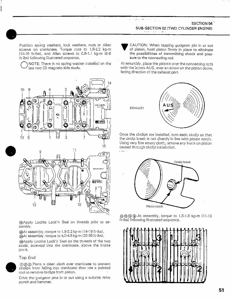
Position spring washers, lock washers, nuts or Allenscrews on crankcase. Torque nuts to 1.9-2.2 kg-m(14-16 ft-lbs{, and Allen screws to 0.8-1.1 kg-m (6-8ft-lbs) following illustrated sequence.
'""\NOTE: There is no spring washer installed on thelast two (2) magneto side studs.
16 8
12
©Apply Loctite Lock'n Seal on threads prior to as-sembly.@At assembly, torque to 1.9-2.2 kg-m (14-16 ft-lbs).@At assembly, torque to 4.0-4.8 kg-m (29-35 ft-lbs).
@Apply Loctite Lock'n Seal on the threads of the twostuds, screwed into the crankcase, above the intakeports.
Top End
©©©Place a clean cloth over crankcase to preventcirciips from falling into crankcase then use a pointedtool to remove circiips from piston.
Drive the gudgeon pins in or out using a suitable drivepunch and hammer.
V CAUTION: When tapping gudgeon pin in or outof piston, hold piston firmly in place to eliminatethe possibilitites of transmitting shock and pres-sure to the connecting rod.
At assembly, place the pistons over the connecting rodswith the letters AUS, over an arrow on the piston dome,facing direction of the exhaust port.
EXHAUST
Once the circiips are installed, turn each circlip so thatthe circlip break is not directly in line with piston notch.Using very fine emery cloth, remove any burrs on pistoncaused through circlip installation.
Circlip break
Piston notch
assembly, torque to 1.5-1.8 kg-m (11-13ft-lbs) following illustrated sequence.
51

SECTION 04SU8-SECTN>N 02 iTWO:CYl(NDER ENGEINE)
NOTE; To prevent leakage, install exhaust mani-fold prior to cylinder head tightening.
© A t assembly, torque to 1.9-2.2 kg-m (14-16 ft-lbs).
Rotary Valve Mechanism
®.®At assembly, apply crankcase sealant on rotaryvalve gear and bearing mating surfaces.
j Rotary valve gear
Ballbearing ' Apply crankcasesealant here
©• To correctly install the rotary valve disc proceed as
follows:
— Bring magneto side piston to T.D.C. using a TopDead Center Gauge (See Tools Section).
~ Position the rotary valve disc on gear so that bothedges fall within range of 6 mm (% ") on either sideof timing marks.
O NOTE: The rotary valve disc is asymetrical. There-fore, at assembly try positioning each side of discon gear to determine best installation position.
1 6mm {'/.") Magneto side pistonmust beat T.D.C.
©to© To remove rotary valve shaft assembly fromcrankcase a special puller is needed. (See Tools Sec-tion). First remove locking ring then position specialpuller over shaft bore and screw puller bolt into rotaryvalve shaft. While holding puller bolt, turn puller nutclockwise until shaft comes out.
©At assembly, position square edge of locking ringagainst shaft shoulder as illustrated.
Square edge
i 6mm(/<")
®!At assembly, apply a light coat of Loctite crankcasesealant on end cap sealing surface.
Magneto
© At assembly torque to 1.9-2.2 kg-rn (14-16ft-lbs).
© At assembly torque to 1.3 kg-m (9ft-lbsl.
© With magneto retaining nut removed and hold-onsupport in place, install special puller onto hub. Tightenpuller bolt and at same time, tap on bolt head using ahammer to release magneto from its taper. (See SpecialTools).
52

SECTIONQ4SUB-SECTION02 (TWO CYLINDER ENGINE)
Hold-on siippor I
Flywheel puller
©Ai assembly, apply Loctite Lock'n Seal on screwthreads.
©To facilitate timing procedure, perform primary ad-justment by matching crankcase and armature platemarks.
Aliflniiifl marks
©@ © Whenever a coil is replaces, the air gap (dis-tance between magnet and armature end) must beadjusted.
To check air gap, insert a feeler gauge of correct thick-ness (0.31 mm / .012"-0.45 mm/.018") betweenmagnet and armature ends. To adjust, slacken retainingscrews and relocate armature.
@® Use a cable connector and rubber sleeve as illus-trated, whenever a coil or cable is replaced.
1. Str ipbmmoi insulation from oach end
5mm 5mm
2. Solder wires into connector with resin core typesolder.
3. Slide rubber sleeve over connector ihen heatwith .1 match to shrink slnnvfj,
CLEANING
Discard all oil seals, gaskets and "0" rings. Clean allmetal components in a non-ferrous metal cleaner.
V CAUTION: Clean armature using only a cleancloth.
Scrape off carbon formation from cylinder exhaustports, cylinder heads and piston domes.
O NOTE: The letter "AUS" over an arrow on thepiston dome must be visible after cleaning.
Clean the piston ring grooves with a groove cleanertool, or with a piece of broken ring.Remove old sealant from crankcase mating surfaceswith Bombardier sealant stripper.
V CAUTION: Never use a sharp object to scrapeaway old sealant as score marks incurred are detri-mental to crankcase sealing.
INSTALLATION _
To install engine on vehicle, inverse removal procedure.However, pay attention to the following:
• Check tightness of engine mount nuts,
• After throttle cable installation, check carburetormaximum throttle opening.
• Check pulley alignment.
53

54