185 gb 146 gb - esco power · gear box feed oil pump variable flow 16 ... manual flow control valve...
TRANSCRIPT
KSLVARIABLE FILL FLUID COUPLINGS
185 GB_146 GB 12/10/12 08.12 Pagina 1
INTRODUCTION
1Variable fill fluid couplings - 1210
INTRODUCTION
Transfluid designed the KSL series variable fill fluid coupling toovercome difficulties experienced during ʻstart upʼ and ʻspeedvariationʼ operation for medium or high powered machines,driven by electric motors or internal combustion engines.
WORKING OPERATION
Extremely efficient performance is achieved utilizing the KSLʼsvery simple and effective principle. Oil, as the power medium,is pumped from a sump to the hydrodynamic coupling circuit,where it is finally ʻdrained-offʼ through a series of orifice plugs,back into the sump.
The variable fill principle:By controlling the oil flow to the working circuit through afrequency converter, changes occur inside the couplingʼsworking circuit which alter the couplingʼs slip characteristicsdramatically softening the ʻstart upʼ.
Torque limiting function:Having all the same advantages of fluid couplings, variablefill-drain type fluid couplings build up torque gradually.
Disconnect:Interrupting the oil flow into the coupling empties the workingcircuit and disconnects the input from the output.This disconnect can be accelerated by using the quick releasevalves.
In summary, it is possibile to:• have a long start up acceleration, up to several minutes, for
high inertia machines.• position the driven machine for loading, unloading and
maintenance.• obtain sequential starting for more than one drive motor.• adjust or limit the torque• disconnect the load even with the motor running• use for conveyors, for the reduction of the tension to a
minimum level or the possibility of running at an inspectionspeed.
• vary the speed within a 5:1 range for centrifugal machines.
CHARACTERISTICS
Soft starter The KSL working circuit is gradually filled by oil from an emptycondition to a fully filled one. Such behaviour provides anextremely soft controlled start up, especially with high inertiamachinery. The KSL variable oil feed system is controlled by afrequency converter during the ramp up, producing ideal softstarting.
Accurate speed variationBy remote signal, the KSL always guarantees output speedaccuracy, as required by the operator or control system.Speed variation is also possible by manual flow control valveoperation.A frequency converter electronic bypass is supplied standard.
Vibration DampeningOne of the most important characteristics of KSL fluid couplingis its torsional vibration dampening effect, protecting both thedriven gear box, fan, or pump machinery, as well as the motoror engine.
Overload ProtectionThis is a fluid coupling advantage and a big benefit to users.Even more protection can be achieved by installing “quickrelease valves” which discharge oil from the working circuit in afew seconds, limiting any prolonged overload completely.
High EfficencyThe KSL is an extremely efficient device compared to theconstant filled type fluid coupling, because the working circuitvolume is controlled at the fullest possible level to maintain avery small slip rate.
Shaft Labyrinth SealingThis type of seal helps the KSL series to be a low maintenancemachine.
Ease of MaintenanceThanks to its split casing design, it is possible to remove thecomplete fluid coupling impeller assembly without having tomove either the motor/engine or driven machinery, saving theneed for realignment and costly down time.
OptionalAuxiliary Lubrication unit for prime mover and/or crivenmachine bearing.
ATEX EEx Upon request.
APPLICATIONS
Mills, crushers, conveyors, fans, blowers, pumps, compressors,centrifuges, mixers, generators, marine propulsion drives.
SELECTION
To correctly select the KSL, Transfluid needs to know thefollowing data:• motor/engine type, power and speed• driven machinery type, power, speed and inertia• output speed range• environmental conditions• cooling water/air characteristics• drive and driven shaft dimensions and tolerances• available voltage for motors and instruments
185 GB_146 GB 12/10/12 08.12 Pagina 2
WORKING SCHEME
2Variable fill fluid couplings - 1210
8 3
5
2
4
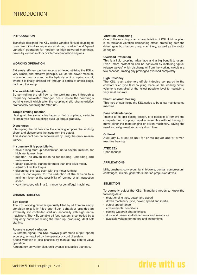
8 - heat exchanger7 - quick release valves6 - bleeding orifices5 - pressure differential transducer4 - pressure gauge3 - heat exchanger oil pump2 - lubrication oil pump
12
13
9
11
7
6
10
15
1
14
15 - temperature gauge14 - pressure gauge13 - vacuum switch
11 - feed oil filter10 - max temperature switch
12 - lub. oil filter
thermostatic controlheat exchanger pump
heat exchanger pump thermostatic control.ou
tput
sp
eed
main drive motor
MPCB
Display speed,
speeds, start up modulation, oil pressure, oil temperature, filter clogging, oil level,
All parameters under control such as:
driven machine
KSL
gear box
feed oil pumpVariable flow
16 - thermocouple Pt100
1 - variable flow feed pump with variable frequency converter
9 - oil level switch and gauge17 - speed sensors
16
17
inp
ut s
igna
ls fr
omCONTROL PANEL
speed settings (4-20 mA)
input/output signals to DCS
sens
ors
and
sw
itche
s
pressure,
from DCS
LOCAL REMOTEtemperature
LOCAL SPEED SETTING
18 - heat exch. pump control19 - manual flow control valve
18
19
PI
IT
AUTOMATIC or SEMIAUTOMATIC / MANUAL or MANUAL
185 GB_146 GB 12/10/12 08.12 Pagina 3
PERFORMANCES
3Variable fill fluid couplings - 1210
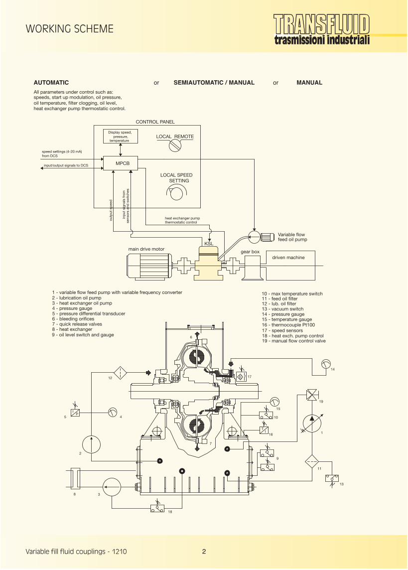
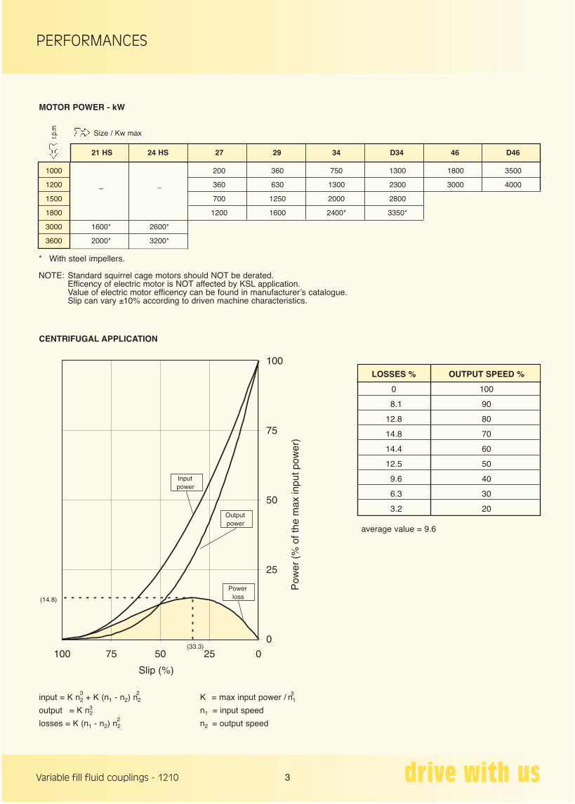
* With steel impellers.
NOTE: Standard squirrel cage motors should NOT be derated. Efficency of electric motor is NOT affected by KSL application. Value of electric motor efficency can be found in manufacturerʼs catalogue. Slip can vary ±10% according to driven machine characteristics.
r.p.m Size / Kw max
21 HS 24 HS 27 29 34 D34 46 D46
1000 200 360 750 1300 1800 3500
1200 – _ 360 630 1300 2300 3000 4000
1500 700 1250 2000 2800
1800 1200 1600 2400* 3350*
3000 1600* 2600*
3600 2000* 3200*
MOTOR POWER - kW
CENTRIFUGAL APPLICATION
LOSSES % OUTPUT SPEED %
0 100
8.1 90
12.8 80
14.8 70
14.4 60
12.5 50
9.6 40
6.3 30
3.2 20
average value = 9.6
input = K n2 + K (n1 - n2) n2
output = K n2
losses = K (n1 - n2) n2
3
3
32
2
K = max input power / n1
n1 = input speed
n2 = output speed
185 GB_146 GB 12/10/12 08.12 Pagina 4
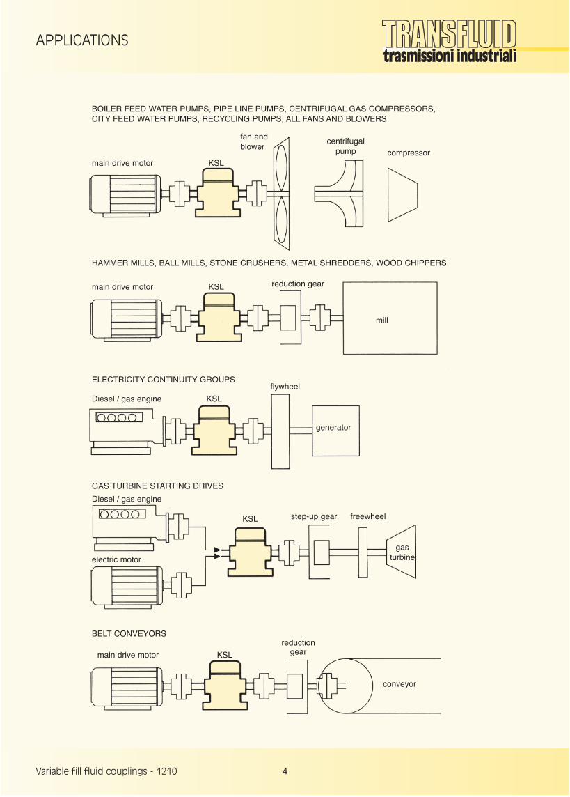
APPLICATIONS
4Variable fill fluid couplings - 1210
BOILER FEED WATER PUMPS, PIPE LINE PUMPS, CENTRIFUGAL GAS COMPRESSORS,CITY FEED WATER PUMPS, RECYCLING PUMPS, ALL FANS AND BLOWERS
HAMMER MILLS, BALL MILLS, STONE CRUSHERS, METAL SHREDDERS, WOOD CHIPPERS
ELECTRICITY CONTINUITY GROUPS
main drive motor KSL
fan andblower
main drive motor KSL reduction gear
mill
main drive motor KSL
reductiongear
conveyor
Diesel / gas engine
electric motor
KSL step-up gear freewheel
gasturbine
Diesel / gas engine KSL
flywheel
generator
centrifugalpump compressor
GAS TURBINE STARTING DRIVES
BELT CONVEYORS
185 GB_146 GB 12/10/12 08.12 Pagina 5
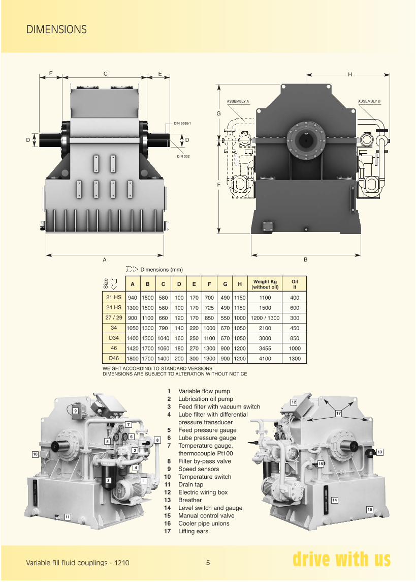
DIMENSIONS
5Variable fill fluid couplings - 1210
WEIGHT ACCORDING TO STANDARD VERSIONSDIMENSIONS ARE SUBJECT TO ALTERATION WITHOUT NOTICE
Siz
e
Dimensions (mm)
A B C D E F G H Weight Kg Oil (without oil) lt 940 1500 580 100 170 700 490 1150 1100 400
1300 1500 580 100 170 725 490 1150 1500 600
900 1100 660 120 170 850 550 1000 1200 / 1300 300
1050 1300 790 140 220 1000 670 1050 2100 450
1400 1300 1040 160 250 1100 670 1050 3000 850
1420 1700 1060 180 270 1300 900 1200 3455 1000
1800 1700 1400 200 300 1300 900 1200 4100 1300
21 HS
24 HS
27 / 29
34
D34
46
D46
1 Variable flow pump 2 Lubrication oil pump 3 Feed filter with vacuum switch 4 Lube filter with differential pressure transducer 5 Feed pressure gauge 6 Lube pressure gauge 7 Temperature gauge, thermocouple Pt100 8 Filter by-pass valve 9 Speed sensors 10 Temperature switch 11 Drain tap 12 Electric wiring box 13 Breather 14 Level switch and gauge 15 Manual control valve 16 Cooler pipe unions 17 Lifting ears
2
3
4
56
7
8
9
10
11
12
13
14
15
16
17
1
D
E EC
D
DIN 6685/1
A
DIN 332
B
F
G
H
ASSEMBLY A ASSEMBLY B
185 GB_146 GB 12/10/12 08.12 Pagina 6
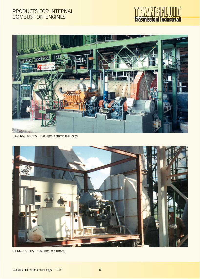
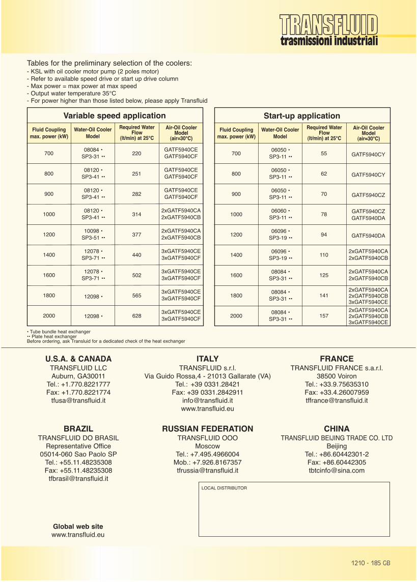
PRODUCTS FOR INTERNALCOMBUSTION ENGINES
6Variable fill fluid couplings - 1210
2x34 KSL, 630 kW - 1000 rpm, ceramic mill (Italy)
34 KSL, 700 kW - 1200 rpm, fan (Brasil)
185 GB_146 GB 12/10/12 08.12 Pagina 7
1210 - 185 GB
Tables for the preliminary selection of the coolers:- KSL with oil cooler motor pump (2 poles motor)- Refer to available speed drive or start up drive column- Max power = max power at max speed- Output water temperature 35°C- For power higher than those listed below, please apply Transfluid
Variable speed application
Fluid Couplingmax. power (kW)
Water-Oil CoolerModel
700
800
900
1000
1200
1400
1600
1800
2000
08084 •SP3-31 ••
08120 •SP3-41 ••
08120 •SP3-41 ••
08120 •SP3-41 ••
10098 •SP3-51 ••
12078 •SP3-71 ••
12078 •SP3-71 ••
12098 •
12098 •
Air-Oil CoolerModel
(air=30°C)
Required WaterFlow
(lt/min) at 25°C
GATF5940CEGATF5940CF
GATF5940CEGATF5940CF
GATF5940CEGATF5940CF
2xGATF5940CA2xGATF5940CB
2xGATF5940CA2xGATF5940CB
3xGATF5940CE3xGATF5940CF
3xGATF5940CE3xGATF5940CF
3xGATF5940CE3xGATF5940CF
3xGATF5940CE3xGATF5940CF
LOCAL DISTRIBUTOR
U.S.A. & CANADATRANSFLUID LLC Auburn, GA30011
Tel.: +1.770.8221777Fax: +1.770.8221774
BRAZILTRANSFLUID DO BRASIL
Representative Office05014-060 Sao Paolo SP
Tel.: +55.11.48235308Fax: +55.11.48235308
ITALYTRANSFLUID s.r.l.
Via Guido Rossa,4 - 21013 Gallarate (VA)Tel.: +39 0331.28421
Fax: +39 [email protected]
RUSSIAN FEDERATIONTRANSFLUID OOO
MoscowTel.: +7.495.4966004
Mob.: [email protected]
FRANCETRANSFLUID FRANCE s.a.r.l.
38500 VoironTel.: +33.9.75635310Fax: [email protected]
CHINATRANSFLUID BEIJING TRADE CO. LTD
BeijingTel.: +86.60442301-2Fax: [email protected]
Start-up application
Fluid Couplingmax. power (kW)
Water-Oil CoolerModel
700
800
900
1000
1200
1400
1600
1800
2000
06050 •SP3-11 ••
06050 •SP3-11 ••
06050 •SP3-11 ••
06060 •SP3-11 ••
06096 •SP3-19 ••
06096 •SP3-19 ••
08084 •SP3-31 ••
08084 •SP3-31 ••
08084 •SP3-31 ••
Air-Oil CoolerModel
(air=30°C)
Required WaterFlow
(lt/min) at 25°C
GATF5940CY
GATF5940CY
GATF5940CZ
GATF5940CZGATF5940DA
GATF5940DA
2xGATF5940CA2xGATF5940CB
2xGATF5940CA2xGATF5940CB
2xGATF5940CA2xGATF5940CB3xGATF5940CE
2xGATF5940CA2xGATF5940CB3xGATF5940CE
55
62
70
78
94
110
125
141
157
220
251
282
314
377
440
502
565
628
• Tube bundle heat exchanger•• Plate heat exchangerBefore ordering, ask Transluid for a dedicated check of the heat exchanger
Global web sitewww.transfluid.eu
185 GB_146 GB 12/10/12 08.12 Pagina 8