17 product details - cspi17 product details & fabrication chapter 2. ... institute (aisi) has...
TRANSCRIPT

INTRODUCTIONVarious design challenges, and the application of corrugated steel pipe and otherproducts to the solution of those challenges, have been described and illustrated inChapter 1. These cover a wide segment of the construction field, including highways,railways, streets, urban areas, airports, industrial and commercial development, floodcontrol and conservation.
These examples are not all-inclusive or complete solutions. They are intendedonly to show the adaptability and wide acceptance of one material - steel - for aidingin the solution of some of the problems facing the design engineer.
So vast are the annual expenditures for construction that the skills of resourcefulqualified engineers are required to research (analyse), select, design and apply theavailable materials and products that most economically serve their purpose. Forexample, the cost of drainage facilities on the original U.S. interstate highway systemwas anticipated to be $4 billion, exclusive of bridges. Mass transportation, anti-pollution facilities, flood protection and other related construction projects canrequire drainage facilities in comparable measure. The need for carefully consideringthe economics of providing and maintaining these facilities is obvious.
Design FactorsDrainage design begins with reconnaissance and location surveys. The services ofexperienced soils and drainage engineers provide the best assurance of economicalconstruction and subsequent minimum maintenance.
The following design factors must be considered:1. Size, shape, alignment, grade and other configurations. These depend on
hydrology and hydraulics, and on service requirements. (See Chapters3, 4 and 5.)
2. Structural adequacy to meet embankment and superimposed live loads,along with hydraulic forces. (See Chapter 6.)
3. Trouble-free service through selection of materials to resist wear andprovide durability. (See Chapter 8.)
4. Economics - First cost of materials and installation, plus maintenancecost evaluated on the basis of present worth. (See Chapter 9.)
In addition to these, the design engineer can make a value-analysis of such otherfactors as: suitable sources of supply, probable delivery schedule, influence ofclimate or season of the year, coordination with other construction schedules,supplier’s assistance, and ease of repair or replacement in relation to the importanceor service of the facility.
Alternate materials and designs should be considered so that the final selectionwill provide the most economical and satisfactory solution for the overall facility andits users.
17
PRODUCT DETAILS & FABRICATION
CHAPTER 2

18 STEEL DRAINAGE AND HIGHWAY CONSTRUCTION PRODUCTS
Background of Corrugated Steel ConduitsCorrugating a flat sheet has long been known to increase its stiffness and strength.Corrugated steel sheets have been produced almost since the first rolling mill wasbuilt in England in 1784. But it was not until after 1890, when mass-produced steelsheets became abundant, that their use grew rapidly.
Corrugated steel pipe was first developed and used for culverts in 1896. Asexperience was gained in the use of this thin-wall, lightweight, shop-fabricated pipe,the diameters gradually increased to 2400 mm and larger. Fill heights becamegreater, even exceeding 30 m. A further development, in 1931, was structural platepipe with larger corrugations, for field assembly. Diameters up to 8 m and arch spansup to 18 m have been installed successfully.
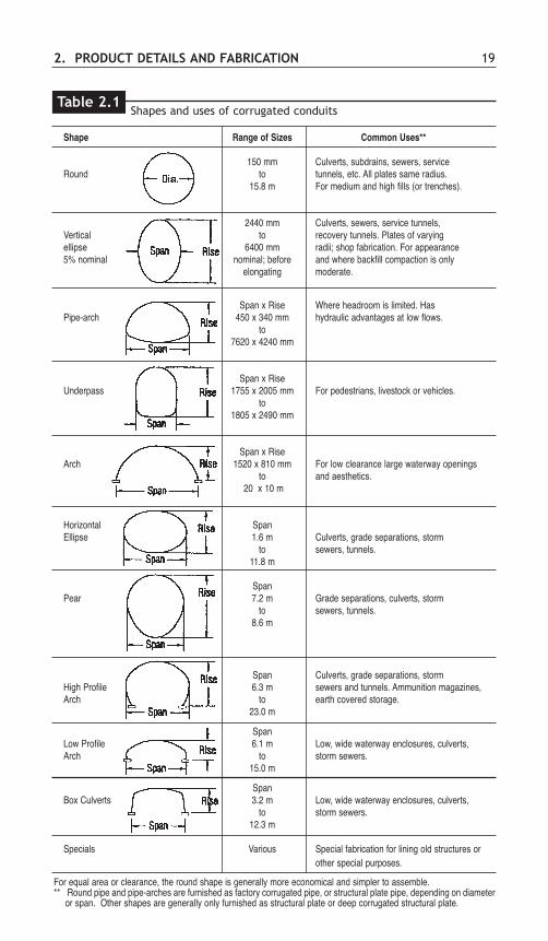
Shapes The designer has a wide choice of standard cross-sectional shapes of corrugated steeland structural plate conduits as shown in Table 2.1. Size and service use may controlthe shape selected, with strength and economy as additional factors.
SECTION A: CORRUGATED STEEL PIPES
Description of CorrugationsThe principal profiles for corrugated steel pipe are shown in Figure 2.1. Corrugationscommonly used for pipes or conduits are circular arcs connected by tangents, and aredescribed by pitch, depth and inside forming radius. Pitch is measured at right anglesto the corrugations from crest to crest. A corrugation is named using its pitch anddepth as “pitch by depth”.
For riveted pipe with circumferential (annular) seams, the corrugations are 68 by13 mm.
For lock seam pipe, the seams and corrugations run helically (or spirally) aroundthe pipe. For small diameters of subdrainage pipe (150, 200, 250 mm) thecorrugation is nominally 38 x 6.5 mm. Larger sizes (diameters to 3600 mm,depending on profile) use 68 x 13 mm, 76 x 25 mm and 125 x 25 mm corrugations.
Another “corrugation” used for lock seam pipe is the spiral rib profile.Developed in the mid 1980's, the pipe wall is spirally formed using rectangularly
Corrugated steel pipe nested for shipment.
2. PRODUCT DETAILS AND FABRICATION 19
Shape Range of Sizes Common Uses**
150 mm Culverts, subdrains, sewers, serviceRound to tunnels, etc. All plates same radius.
15.8 m For medium and high fills (or trenches).
2440 mm Culverts, sewers, service tunnels,Vertical to recovery tunnels. Plates of varyingellipse 6400 mm radii; shop fabrication. For appearance5% nominal nominal; before and where backfill compaction is only
elongating moderate.
Span x Rise Where headroom is limited. HasPipe-arch 450 x 340 mm hydraulic advantages at low flows.
to7620 x 4240 mm
Span x RiseUnderpass 1755 x 2005 mm For pedestrians, livestock or vehicles.
to1805 x 2490 mm
Span x RiseArch 1520 x 810 mm For low clearance large waterway openings
to and aesthetics.20 x 10 m
Horizontal SpanEllipse 1.6 m Culverts, grade separations, storm
to sewers, tunnels.11.8 m
SpanPear 7.2 m Grade separations, culverts, storm
to sewers, tunnels.8.6 m
Span Culverts, grade separations, stormHigh Profile 6.3 m sewers and tunnels. Ammunition magazines, Arch to earth covered storage.
23.0 m
SpanLow Profile 6.1 m Low, wide waterway enclosures, culverts,Arch to storm sewers.
15.0 m
SpanBox Culverts 3.2 m Low, wide waterway enclosures, culverts,
to storm sewers.12.3 m
Specials Various Special fabrication for lining old structures or other special purposes.
For equal area or clearance, the round shape is generally more economical and simpler to assemble.** Round pipe and pipe-arches are furnished as factory corrugated pipe, or structural plate pipe, depending on diameter
or span. Other shapes are generally only furnished as structural plate or deep corrugated structural plate.
Shapes and uses of corrugated conduitsTable 2.1

20 STEEL DRAINAGE AND HIGHWAY CONSTRUCTION PRODUCTS
Figure 2.1 Commonly used corrugations.
All dimensions in millimetres.

Wall Thickness DevelopedTangent Tangent Moment Section Radius of Width
Specified Design Area Length Angle of Inertia Modulus Gyration Factor
T T A TL θθ I S r WF
mm mm mm2/mm mm Degrees mm4/mm mm3/mm mm *
1.3 1.12 1.187 14.367 21.519 5.11 1.37 2.075 1.0601.6 1.40 1.484 14.242 21.597 6.46 1.67 2.087 1.0602.0 1.82 1.929 14.054 21.717 8.58 2.10 2.109 1.060
2. PRODUCT DETAILS AND FABRICATION 21
Section design properties for corrugated CSP sheetCorrugation profile: 38 x 6.5 mm (helical)
Table 2.2
*WF is the ratio of the flat sheet width to the corrugated sheet width.NOTE: Dimensions are subject to manufacturing tolerances.
formed ribs between flat wall areas. This unique profile configuration was developedfor providing flow characteristics equal to those piping systems normally consideredsmooth wall. One profile configuration is available, with nominal dimensions 19 x19 x 190 mm (rib pitch x rib depth x rib spacing), covering diameters from 450through 2700 mm.
Section PropertiesSection properties of the arc-and-tangent type of corrugation are derivedmathematically using a design thickness which is a little different than the measuredor specified thickness. The properties include area, A, moment of inertia, I, sectionmodulus, S, and radius of gyration, r. Research by the American Iron and SteelInstitute (AISI) has shown that failure loads in bending and deflection within theelastic range can be closely predicted by using computed section properties of thecorrugated sheet. See Tables 2.2 through 2.6.
Sizes and ShapesThe number of corrugation profiles available is a result of the need for additionalstiffness and strength for larger diameters of pipes. The standard sizes of round andpipe-arch corrugated steel pipes and spiral rib steel pipes, and their handling weights,are shown in Tables 2.7 through 2.11.

22 STEEL DRAINAGE AND HIGHWAY CONSTRUCTION PRODUCTS
Section design properties for corrugated CSP sheetCorrugation profile: 68 x 13 mm (annular or helical)
Table 2.3
Wall Thickness DevelopedTangent Tangent Moment Section Radius of Width
Specified Design Area Length Angle of Inertia Modulus Gyration Factor
T T A TL θθ I S r WF
mm mm mm2/mm mm Degrees mm4/mm mm3/mm mm *
1.3 1.120 1.209 19.759 26.647 22.61 3.27 4.324 1.0791.6 1.400 1.512 19.578 26.734 28.37 4.02 4.332 1.0802.0 1.820 1.966 19.304 28.867 37.11 5.11 4.345 1.0802.8 2.640 2.852 18.765 27.136 54.57 7.11 4.374 1.0803.5 3.350 3.621 18.269 27.381 70.16 8.74 4.402 1.0814.2 4.080 4.411 17.755 27.643 86.71 10.33 4.433 1.081
*WF is the ratio of the flat sheet width to the corrugated sheet width.NOTE: Dimensions are subject to manufacturing tolerances.

2. PRODUCT DETAILS AND FABRICATION 23
Wall Thickness DevelopedTangent Tangent Moment Section Radius of Width
Specified Design Area Length Angle of Inertia Modulus Gyration Factor
T T A TL θθ I S r WF
mm mm mm2/mm mm Degrees mm4/mm mm3/mm mm *
1.3 1.12 1.389 24.159 44.389 103.96 7.84 8.653 1.2401.6 1.40 1.736 23.862 44.580 130.40 9.73 8.666 1.2402.0 1.82 2.259 23.411 44.875 170.40 12.52 8.685 1.2412.8 2.64 3.281 22.504 45.479 249.73 17.81 8.724 1.2433.5 3.35 4.169 21.688 46.035 319.77 22.24 8.758 1.2444.2 4.08 5.084 20.815 46.645 393.12 26.67 8.794 1.246
Section design properties for corrugated CSP sheetCorrugation profile: 76 x 25 mm (annular or helical)
Table 2.4
*WF is the ratio of the flat sheet width to the corrugated sheet width.NOTE: Dimensions are subject to manufacturing tolerances.

Wall Thickness Elastic Plastic DevelopedTangent Tangent Moment Section Section Radius of Width
Specified Design Area Length Angle of Inertia Modulus Modulus Gyration Factor
T T A TL θθ I S Z r WF
mm mm mm2/mm mm Degrees mm4/mm mm3/mm mm3/mm mm *
1.6 1.40 1.549 18.568 35.564 133.30 9.73 12.94 9.277 1.1062.0 1.82 2.014 17.970 35.811 173.72 12.49 16.86 9.287 1.1072.8 2.64 2.923 16.742 36.330 253.24 17.68 24.54 9.308 1.1073.5 3.35 3.711 15.600 36.826 322.74 21.99 31.24 9.326 1.1084.2 4.08 4.521 14.332 37.392 394.84 26.25 38.17 9.345 1.108
24 STEEL DRAINAGE AND HIGHWAY CONSTRUCTION PRODUCTS
Section design properties for corrugated CSP sheetCorrugation profile: 125 x 25 mm (helical)
Table 2.5
*WF is the ratio of the flat sheet width to the corrugated sheet width.NOTE: Dimensions are subject to manufacturing tolerances.

Wall Thickness DevelopedMoment Section Radius of Width
Specified Design Area of Inertia Modulus Gyration Factor
T T A I S r WF
mm mm mm2/mm mm4/mm mm3/mm mm *
1.6 1.519 1.082 58.829 4.016 7.375 1.1702.0 1.897 1.513 77.674 5.054 7.164 1.1682.8 2.657 2.523 117.167 7.129 6.815 1.165
2. PRODUCT DETAILS AND FABRICATION 25
Section design properties for spiral rib pipeRib profile: 19 x 19 x 190 mm (helical)
Table 2.6
*WF is the ratio of the flat sheet width to the corrugated sheet width.Properties are effective section properties at full yield stress.Note: Dimensions are subject to manufacturing tolerances.
Placing and checking of elevation of pipe bedding.

26 STEEL DRAINAGE AND HIGHWAY CONSTRUCTION PRODUCTSCo
rrug
ated
ste
el p
ipe
(CSP
) -
stan
dard
rou
nd d
iam
eter
s, e
nd a
reas
, an
d ha
ndlin
g w
eigh
ts (
kg/m
)**
Asph
alt-C
oate
d,As
phal
t-Coa
ted,
Plai
n M
etal
lic C
oate
dAs
phal
t-Coa
ted
*Pav
ed-In
vert
Smoo
th-L
ined
A.
Cor
ruga
tion
Prof
ile: 3
8 x
6.5
mm
End
Spec
ified
Wal
l Thi
ckne
ss, m
mDi
amet
er,
Area
,m
mm
21.
31.
62.
02.
83.
54.
21.
31.
62.
02.
83.
54.
2
150
0.01
85.
97.
2-
--
-7.
28.
5-
--
-20
00.
031
7.7
9.5
--
--
9.4
11-
--
-25
00.
049
9.6
12-
--
-12
14-
--
-
End
B.Co
rrug
atio
n Pr
ofile
: 68
x 13
mm
Diam
eter
,Ar
ea,
Spec
ified
Wal
l Thi
ckne
ss,m
m
mm
m2
1.3
1.6
2.0
2.8
3.5
4.2
1.3
1.6
2.0
2.8
3.5
4.2
1.3
1.6
2.0
2.8
3.5
4.2
1.3
1.6
2.0
2.8
3.5
4.2
300
0.07
1214
18-
--
1517
21-
--
1719
23-
--
2224
28-
--
400
0.13
1619
24-
--
2023
28-
--
2225
30-
--
3033
38-
--
500
0.20
1924
3041
--
2429
3546
--
2732
3849
--
3641
4758
--
600
0.28
2328
3549
--
2833
4054
--
3237
4458
--
4449
5670
--
700
0.38
-33
4157
--
-39
4763
--
-44
5268
--
-57
6581
--
800
0.50
-37
4765
--
-44
5472
--
-49
5977
--
-64
7492
--
900
0.64
-42
5373
9010
8-
5061
8198
116
-56
6787
104
122
-73
8410
412
113
910
000.
79-
4758
8110
012
0-
5667
9010
912
9-
6273
9611
513
5-
8192
115
134
154
1200
1.13
-56
7097
120
144
-66
8010
713
015
4-
7488
115
138
162
-97
111
138
161
185
1400
1.54
--
8111
314
016
8-
-93
125
152
180
--
102
134
161
189
--
129
161
188
216
1600
2.01
--
9313
016
019
2-
-10
714
417
420
6-
-11
715
418
421
6-
-14
818
521
524
718
002.
54-
--
146
179
215
--
-16
219
523
1-
--
174
206
242
--
-20
824
127
720
003.
14-
--
162
199
239
--
-17
921
625
6-
--
192
229
269
--
-23
026
730
722
003.
80-
--
-21
926
3-
--
-23
828
2-
--
-25
229
6-
--
-29
433
824
004.
52-
--
--
287
--
--
-30
8-
--
--
323
--
--
-36
9
NOTE
S:*
Wei
ght b
ased
on
a pa
vem
ent c
over
ing
25%
of t
he p
erip
hery
. **
Oth
er c
orru
gatio
n pr
ofile
s in
Tab
le 2
.8.
1. T
he w
eigh
ts a
re b
ased
on
helic
al lo
ckse
am fa
brica
tion,
and
are
app
roxim
ate.
Rive
ted
CSP
weig
hs s
light
ly m
ore.
2.Ha
ndlin
g we
ight
s no
t sho
wn in
dica
te th
at p
artic
ular
size
or s
teel
thick
ness
is e
ither
not
gen
eral
ly re
com
men
ded
prac
tice,
or m
ay n
ot b
e po
ssib
le to
fabr
icate
. Man
y siz
e/th
ickne
ss c
ombi
natio
nsno
t sho
wn m
ay b
e av
aila
ble.
For
furth
er o
r spe
cific
deta
ils, c
onsu
lt yo
ur lo
cal C
SPfa
brica
tors
.
Tabl
e 2.
7

2. PRODUCT DETAILS AND FABRICATION 27As
phal
t-Coa
ted,
Asph
alt-C
oate
d,Pl
ain
Met
allic
Coa
ted
Asph
alt-C
oate
d*P
aved
-Inve
rtSm
ooth
-Lin
edC.
Cor
ruga
tion
Prof
ile: 7
6 x
25 m
mEn
dSp
ecifie
d W
all T
hick
ness
, mm
Diam
eter
,Ar
ea,
mm
m2
1.6
2.0
2.8
3.5
4.2
1.6
2.0
2.8
3.5
4.2
1.6
2.0
2.8
3.5
4.2
1.6
2.0
2.8
3.5
4.2
1200
1.13
6581
112
--
7793
124
--
9010
613
7-
-13
014
617
7-
-14
001.
5475
9413
116
1-
8910
814
517
5-
104
124
160
190
-15
117
020
723
7-
1600
2.01
8610
714
918
422
110
212
316
520
023
712
014
118
321
825
517
319
423
627
130
818
002.
5496
120
167
206
248
114
138
185
224
266
134
158
205
244
286
194
218
264
304
346
2000
3.14
107
133
186
229
275
127
153
206
249
295
149
175
228
271
317
215
241
294
337
383
2200
3.80
117
147
204
252
302
139
169
226
274
324
163
193
250
298
348
236
266
323
371
421
2400
4.52
128
160
221
274
329
152
184
245
298
353
178
210
272
324
380
258
290
351
404
459
2700
5.73
144
179
250
308
370
171
206
277
335
397
201
236
307
365
427
290
325
396
454
516
3000
7.07
-19
927
834
241
1-
229
308
372
441
-26
234
140
547
4-
362
440
504
574
3300
8.55
--
305
376
451
--
338
409
484
--
374
445
520
--
484
555
630
3600
10.1
8-
--
410
492
--
-44
652
8-
--
486
568
--
-60
568
7D.
Cor
ruga
tion
Prof
ile: 1
25 x
25
mm
End
Spec
ified
Wal
l Thi
ckne
ss, m
mDi
amet
er,
Area
,m
mm
21.
62.
02.
83.
54.
21.
62.
02.
83.
54.
21.
62.
02.
83.
54.
21.
62.
02.
83.
54.
212
001.
1357
7110
012
4-
6882
111
135
-82
9612
414
8-
123
137
166
190
-14
001.
5466
8311
614
4-
7996
129
157
-95
112
145
173
-14
316
019
322
1-
1600
2.01
7695
132
165
197
9010
914
717
921
110
812
716
519
823
016
318
222
025
228
418
002.
5485
106
148
185
221
101
122
165
201
237
122
143
185
222
258
184
205
247
284
320
2000
3.14
9411
816
520
524
511
213
618
322
326
313
615
920
624
628
620
422
827
431
535
522
003.
8010
412
918
122
526
912
314
920
124
528
914
917
522
627
031
422
425
030
234
639
024
004.
5211
314
119
724
529
313
516
321
926
731
516
219
024
729
534
324
527
332
937
742
527
005.
7312
715
922
227
633
015
118
324
630
035
418
321
427
733
138
527
530
737
042
447
830
007.
07-
176
246
306
366
-20
327
333
339
3-
238
307
368
428
-34
041
047
053
033
008.
55-
-27
033
640
2-
-30
036
643
2-
-33
840
447
0-
-45
151
758
336
0010
.18
--
-36
743
8-
--
399
470
--
-44
051
1-
--
564
635
NOTE
: *
Wei
ght b
ased
on
a pa
vem
ent c
over
ing
25%
of t
he p
erip
hery
. **
Oth
er c
orru
gatio
n pr
ofile
s in
Tab
le 2
.7.
1. T
he w
eigh
ts a
re b
ased
on
helic
al lo
ckse
am fa
brica
tion,
and
are
app
roxim
ate.
Rive
ted
CSP
weig
hs s
light
ly m
ore.
2.Ha
ndlin
g we
ight
s no
t sho
wn in
dica
te th
at p
artic
ular
size
or s
teel
thick
ness
is e
ither
not
gen
eral
ly re
com
men
ded
prac
tice,
or m
ay n
ot b
e po
ssib
le to
fabr
icate
. Man
y siz
e/th
ickne
ss c
ombi
natio
nsno
t sho
wn m
ay b
e av
aila
ble.
For
furth
er o
r spe
cific
deta
ils, c
onsu
lt yo
ur lo
cal C
SPfa
brica
tors
.
Corr
ugat
ed s
teel
pip
e (C
SP)
- st
anda
rd r
ound
dia
met
ers,
end
are
as,
and
hand
ling
wei
ghts
(kg
/m)*
*Ta
ble
2.8

28 STEEL DRAINAGE AND HIGHWAY CONSTRUCTION PRODUCTSCS
P pi
pe-a
rch
shap
es a
nd h
andl
ing
wei
ghts
(kg
/m)
Asph
alt-C
oate
dPl
ain
Met
allic
Coa
ted
Asph
alt-C
oate
d**
Pave
d-In
vert
Equi
vale
ntRo
und
End
Spec
ified
Wal
l Thi
ckne
ss, m
mSp
an x
Rise
,Di
amet
er,
Area
,m
mm
mm
21.
62.
02.
83.
54.
21.
62.
02.
83.
54.
21.
62.
02.
83.
54.
2
A. C
orru
gatio
n Pr
ofile
: 68
x 13
mm
450
x 34
040
00.
1119
24-
--
2328
--
-26
31-
--
560
x 42
050
00.
1924
3041
--
2935
46-
-34
4051
--
680
x 50
060
00.
2728
3549
--
3340
54-
-39
4660
--
800
x 58
070
00.
3733
4157
--
3947
63-
-46
5470
--
910
x 66
080
00.
4837
4765
--
4454
72-
-52
6280
--
1030
x 7
4090
00.
6142
5373
9010
850
6181
9811
659
7090
107
125
1150
x 8
2010
000.
7447
5881
100
120
5667
9010
912
966
7710
011
913
913
90 x
970
1200
1.06
5670
9712
014
466
8010
713
015
478
9211
914
216
616
30 x
112
014
001.
44-
8111
314
016
8-
9312
515
218
0-
107
139
166
194
1880
x 1
260
1600
1.87
-93
130
160
192
-10
714
417
420
6-
123
160
190
222
2130
x 1
400
1800
2.36
--
146
179
215
--
162
195
231
--
180
213
249
B. C
orru
gatio
n Pr
ofile
: 125
x 2
5 m
m
1780
x 1
360
1600
1.93
-95
132
165
--
109
147
179
--
127
165
198
-20
10 x
153
018
002.
44-
106
148
185
--
122
165
201
--
143
185
222
-22
30 x
170
020
002.
97-
118
165
205
245
-13
618
322
326
3`-
159
206
246
286
2500
x 1
830
2200
3.44
-12
918
122
526
9-
149
201
245
289
-17
522
627
031
428
00 x
195
024
004.
27-
141
197
245
293
-16
321
926
731
5-
190
247
295
343
3300
x 2
080
2700
5.39
--
222
276
330
--
246
300
354
--
277
331
385
3650
x 2
280
3000
6.60
--
-30
636
6-
--
333
393
--
-36
842
838
90 x
269
033
008.
29-
--
-40
2-
--
-43
2-
--
-47
043
70 x
287
036
009.
76-
--
-43
8-
--
470
--
--
511
Note
s:**
Wei
ght b
ased
on
a pa
vem
ent c
over
ing
40%
of t
he p
erip
hery
.1.
The
wei
ghts
are
bas
ed o
n he
lical
lock
seam
fabr
icatio
n, a
nd a
re a
ppro
ximat
e. R
ivete
d CS
Pwi
ll we
igh
sligh
tly m
ore.
2.Ha
ndlin
g we
ight
s no
t sho
wn in
dica
te th
at p
artic
ular
size
or s
teel
thick
ness
is e
ither
not
gen
eral
ly re
com
men
ded
prac
tice,
or m
ay n
ot b
e po
ssib
le to
fabr
icate
. Man
y siz
e/th
ickne
ss c
ombi
natio
nsno
t sho
wn m
ay b
e av
aila
ble.
For
furth
er o
r spe
cific
deta
ils, c
onsu
lt yo
ur lo
cal C
SPfa
brica
tors
.
Tabl
e 2.
9
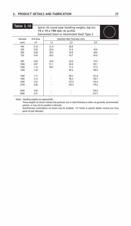
Diameter End Area Specified Wall Thickness (mm)(mm) m2 1.6 2.0 2.8
450 0.16 21.9 26.8 -525 0.22 25.6 31.3 42.6600 0.28 29.2 35.8 48.6750 0.44 36.5 44.7 60.8
900 0.64 43.8 53.6 72.91050 0.87 51.1 62.6 85.11200 1.13 58.4 71.5 97.31350 1.43 - 80.5 109.4
1500 1.77 - 89.4 121.61650 2.14 - 98.3 133.71800 2.54 - 107.3 145.92100 3.46 - 125.2 170.2
2400 4.52 - - 194.52600 5.31 - - 210.7
Notes: Handling weights are approximate.Those weights not shown indicate that particular size or steel thickness is either not generally recommendedpractice, or may not be possible to fabricate.Size/thickness combinations not shown may be available. For further or specific details, consult your localspiral rib pipe fabricator.
2. PRODUCT DETAILS AND FABRICATION 29
Spiral rib round pipe handling weights (kg/m): 19 x 19 x 190 mm rib profileGalvanized Steel or Aluminized Steel Type 2
Table 2.10
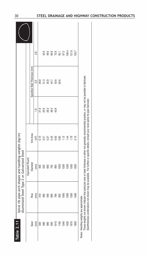
30 STEEL DRAINAGE AND HIGHWAY CONSTRUCTION PRODUCTSSp
iral
rib
pip
e-ar
ch s
hape
s an
d ha
ndlin
g w
eigh
ts (
kg/m
)Al
umin
ized
Ste
el T
ype
2 or
Gal
vani
zed
Stee
l
Tabl
e 2.
11
Equi
vale
nt R
ound
Span
Rise
Diam
eter
End
Area
Spec
ified
Wal
l Thi
ckne
ss (m
m)
(mm
)(m
m)
(mm
)(m
2 )1.
62.
02.
850
041
045
00.
1521
.926
.858
049
052
50.
2125
.631
.342
.668
054
060
00.
2729
.235
.848
.683
066
075
00.
4336
.544
.760
.810
1079
090
00.
6243
.853
.672
.911
6092
010
500.
8562
.685
.113
4010
5012
001.
1297
.315
2012
0013
501.
4410
9.4
1670
1300
1500
1.79
121.
618
5014
0016
502.
1513
3.7
Note
s: H
andl
ing
weig
hts
are
appr
oxim
ate.
Thos
e we
ight
s no
t sho
wn in
dica
te th
at p
artic
ular
size
or s
teel
thick
ness
is e
ither
not
gen
eral
ly re
com
men
ded
prac
tice,
or m
ay n
ot b
e po
ssib
le to
fabr
icate
.Si
ze/th
ickne
ss c
ombi
natio
ns n
ot s
hown
may
be
avai
labl
e. F
or fu
rther
or s
pecif
ic de
tails
, con
sult
your
loca
l spi
ral r
ib p
ipe
fabr
icato
r.
2. PRODUCT DETAILS AND FABRICATION 31
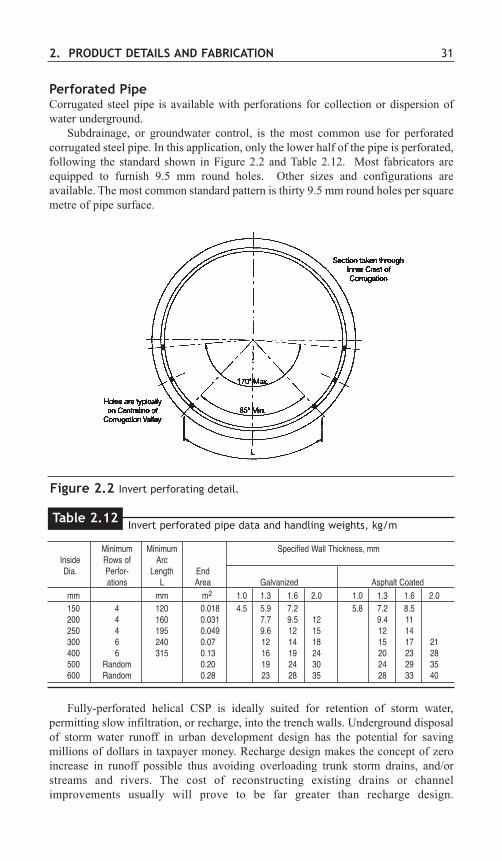
Perforated PipeCorrugated steel pipe is available with perforations for collection or dispersion ofwater underground.
Subdrainage, or groundwater control, is the most common use for perforatedcorrugated steel pipe. In this application, only the lower half of the pipe is perforated,following the standard shown in Figure 2.2 and Table 2.12. Most fabricators areequipped to furnish 9.5 mm round holes. Other sizes and configurations areavailable. The most common standard pattern is thirty 9.5 mm round holes per squaremetre of pipe surface.
Minimum Minimum Specified Wall Thickness, mmInside Rows of ArcDia. Perfor- Length End
ations L Area Galvanized Asphalt Coated mm mm m2 1.0 1.3 1.6 2.0 1.0 1.3 1.6 2.0150 4 120 0.018 4.5 5.9 7.2 5.8 7.2 8.5200 4 160 0.031 7.7 9.5 12 9.4 11250 4 195 0.049 9.6 12 15 12 14300 6 240 0.07 12 14 18 15 17 21400 6 315 0.13 16 19 24 20 23 28500 Random 0.20 19 24 30 24 29 35600 Random 0.28 23 28 35 28 33 40
Invert perforated pipe data and handling weights, kg/mTable 2.12
Figure 2.2 Invert perforating detail.
Fully-perforated helical CSP is ideally suited for retention of storm water,permitting slow infiltration, or recharge, into the trench walls. Underground disposalof storm water runoff in urban development design has the potential for savingmillions of dollars in taxpayer money. Recharge design makes the concept of zeroincrease in runoff possible thus avoiding overloading trunk storm drains, and/orstreams and rivers. The cost of reconstructing existing drains or channelimprovements usually will prove to be far greater than recharge design.

32 STEEL DRAINAGE AND HIGHWAY CONSTRUCTION PRODUCTS
Figure 2.3 Typical corrugated steel conveyor cover with removable cover sheets.
Conveyor CoversPerhaps the most commonly used cover is a half-circle steel arch section(Figure 2.3), 1220 mm long, supported on band sheets 250 mm wide. These bandsheets in turn are supported by bolting to the conveyor frame.
Diameters of support bands and cover sheets are optional, to meet the conveyorequipment manufacturer's designs, but usually range from 600 to 1800 mm. Thecorrugated sheets are supplied in suitable thicknesses of steel. Cover sheets aresecured by one bolt at each corner and can be removed quickly when necessary.Preferably the corrugations should run transverse to the conveyor for greater strengthwith minimum framing. Where the arch covers not only the conveyor belt but alsothe walkway, sheets with larger corrugations (125 x 25 mm or 152 x 51 mm) can beprovided.
A horseshoe shape is used where weighing equipment or other facilities requirea high cover. A circular or elliptical shape can also serve as a beam to strengthen thespan between bents in aerial conveyor systems.
Environmental considerations also favour recharge design. Natural streams can bemaintained for fish passage, and water-poor areas can be enriched. See Chapter 6 ofModern Sewer Design for further details. In this application, the pipe is perforatedfor the full 360 degrees. Perforations in fully perforated helical pipe usually provideand opening area of not less than 2.3% of the pipe surface.
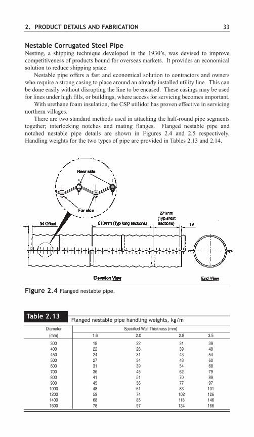
Nestable Corrugated Steel PipeNesting, a shipping technique developed in the 1930’s, was devised to improvecompetitiveness of products bound for overseas markets. It provides an economicalsolution to reduce shipping space.
Nestable pipe offers a fast and economical solution to contractors and ownerswho require a strong casing to place around an already installed utility line. This canbe done easily without disrupting the line to be encased. These casings may be usedfor lines under high fills, or buildings, where access for servicing becomes important.
With urethane foam insulation, the CSP utilidor has proven effective in servicingnorthern villages.
There are two standard methods used in attaching the half-round pipe segmentstogether; interlocking notches and mating flanges. Flanged nestable pipe andnotched nestable pipe details are shown in Figures 2.4 and 2.5 respectively.Handling weights for the two types of pipe are provided in Tables 2.13 and 2.14.
2. PRODUCT DETAILS AND FABRICATION 33
Figure 2.4 Flanged nestable pipe.
Diameter Specified Wall Thickness (mm)(mm) 1.6 2.0 2.8 3.5
300 18 22 31 39400 22 28 39 49450 24 31 43 54500 27 34 48 60600 31 39 54 68700 36 45 62 79800 41 51 70 89900 45 56 77 971000 48 61 83 1011200 59 74 102 1261400 68 85 118 1461600 78 97 134 166
Flanged nestable pipe handling weights, kg/mTable 2.13

34 STEEL DRAINAGE AND HIGHWAY CONSTRUCTION PRODUCTS
Figure 2.5 Notched nestable pipe can be joined with stitches or a hook andeye bolt assembly.
Diameter Specified Wall Thickness (mm)(mm) 1.6 2.0 2.8 3.5 4.2
300 15 19 26 32 38400 20 25 34 42 50450 23 29 38 47 57500 25 32 43 53 63600 29 37 51 63 76700 34 43 59 73 88800 39 49 68 84 100900 44 56 77 95 1131000 49 61 85 105 1261200 59 74 102 126 1511400 69 85 119 147 1761600 78 98 137 168 2021800 88 110 153 118 2262000 98 122 170 210 252
Notched nestable pipe handling weights, kg/mTable 2.14
Ditch LinerHalf-round flanged nestable pipe is used widely as a flume or downslope drain. Woodsills and cross-braces with anchors embedded in the embankment stabilize the flume.
Concrete Lined CSPThis product consists of a corrugated steel pipe with an interior lining composed of anextremely dense, high strength concrete. The lining provides a superior wearingsurface for extended structure life as well as a smooth interior for improved hydraulics.
CSP Slotted Drain InletsBy welding a narrow section of grating in the top of a corrugated steel pipe, acontinuous grate inlet is achieved. Originally conceived to pick up sheet flow inroadway medians, parking lots, airports, etc., this product has proven even more usefulin curb inlets. Detailed hydraulic design information is provided in Chapter 4,Hydraulics.

2. PRODUCT DETAILS AND FABRICATION 35
CSP slotted drain inlet.

36 STEEL DRAINAGE AND HIGHWAY CONSTRUCTION PRODUCTS
SECTION B: STRUCTURAL PLATE AND DEEPCORRUGATED STRUCTURAL PLATE PRODUCTS
1. STRUCTURAL PLATE
Product DescriptionStructural plate pipes are structures where corrugated steel sections are boltedtogether to form the shape of the structure. The sections are commonly referred to asplates.
The structural plate 152 x 51 mm corrugation is the standard in the Canadianstructural plate industry. The corrugation is shown in Figure 2.1.
The corrugations are at right angles to the length of the plate. The length of aplate is measured in a direction parallel to the length of the structure. The width ofa plate is, therefore, measured in a direction perpendicular to the length of thestructure, around the periphery of the structure.
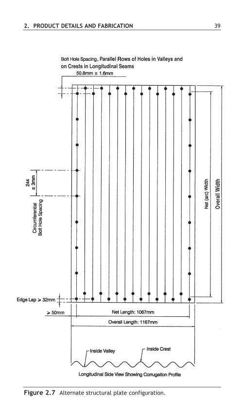
Standard plates are fabricated in three lengths and several widths, as shown inTable 2.15 and Figures 2.6 and 2.7. The plate width designation, N, is used todescribe the various plate widths available. N is the distance between twocircumferential bolt holes, or one circumferential bolt hole space (circumferentialrefers to the direction around the periphery of the structure, at right angles to thelength of the structure). For instance, a 5N plate has a net width of 5 circumferentialbolt hole spaces (see Figure 2.6) and an 8N plate has a net width of 8 circumferentialbolt hole spaces (see Figure 2.7). The bolt hole space, N, is 9.6 inches or 243.84 mm(244 mm nominal). Note that not all widths are available in all lengths. The width-length combinations are shown in Table 2.16.
Plates are furnished curved to various radii and are clearly identified by thefabricator for field assembly.
The plates are available in thicknesses from 3.0 to 7.0 mm.Masses of individual plate sections are shown in Table 2.16. While the correct
terminology is “mass”, the term “weight” will be used in the following text andtables. Approximate weights of structural plate structures are readily calculatedusing these values.
Section PropertiesSection properties, used for design, are provided in Table 2.17. As with corrugatedsteel pipe corrugations, properties of the arc-and-tangent structural plate corrugationare derived mathematically using the design thickness. The properties in the tableinclude area, moment of inertia, section modulus and radius of gyration.
Sizes and ShapesThe plates are assembled into various shapes as indicated in Tables 2.18 through2.26. The shapes include round, pipe-arch, single radius arch, horizontal ellipse, lowprofile arch, high profile arch, pear, underpass and vertical ellipse. Special shapes,and other sizes of standard shapes beyond what is shown in the tables, are alsoavailable. Detailed assembly instructions accompany each structure.

2. PRODUCT DETAILS AND FABRICATION 37
Approximate Weight of Galvanized Plates1, kg Number Specified Wall Thickness, mm of
Plate Width Length, AssemblyDesignation mm 3 4 5 6 7 Bolts/Plate
5N 3048 132 176 221 265 309 445N 3658 158 211 264 316 369 526N 3048 156 209 261 313 365 456N 3658 187 249 312 374 436 539N 3048 229 305 381 457 534 489N 3658 273 364 456 547 638 563N 1067 30 40 50 60 70 164N 1067 38 51 64 77 90 175N 1067 47 63 78 94 109 186N 1067 58 78 97 117 136 197N 1067 67 90 112 135 157 208N 1067 76 102 127 152 178 219N 1067 85 114 142 170 199 2210N 1067 94 126 157 188 220 2311N 1067 103 138 172 206 241 2412N 1067 112 150 187 224 262 2513N 1067 121 161 202 242 283 2614N 1067 130 173 217 260 304 2715N 1067 139 185 232 278 325 2816N 1067 139 185 232 278 325 29
Weight of structural plate sectionsTable 2.16
Notes 1. Bolt weight not included.
2. For galvanized plate thicknesses 3.0 and 4.0 mm, bolt lengths are 32 and 38 mm; for thicknesses 5.0 and 6.0mm, bolt lengths are 38 and 44 mm; for 7.0 mm thickness, bolt lengths are 38 and 51 mm. Bolts are colourcoded for the different lengths.
3. Weight of bolts and nuts in kg per hundred: 32 mm = 23.6 51 mm = 27.038 mm = 25.0 76 mm = 32.944 mm = 25.9
4. To compute the approximate weight of structure per metre of length: (1) multiply the weight from the table bythe number of plates in the periphery; (2) add weight of bolts and nuts; and (3) divide by plate length.
Nominal PlateWidth No. of
Designation Net Width, Overall Width, Spaces (N) Circumferential Bolt HolesN mm mm at 244 mm
3N 732 846 3 44N 975 1090 4 55N 1219 1334 5 66N 1463 1577 6 77N 1707 1821 7 88N 1951 2065 8 99N 2195 2309 9 1010N 2438 2553 10 1111N 2682 2797 11 1212N 2926 3040 12 1313N 3170 3284 13 1414N 3414 3528 14 1515N 3658 3772 15 1616N 3901 4016 16 17
N = 244 mm nominal (243.84 mm theoretical)
Structural plate sections, 152 x 51 corrugation Profile details of uncurved plates
Table 2.15

38 STEEL DRAINAGE AND HIGHWAY CONSTRUCTION PRODUCTS
Figure 2.6 Configuration of structural plate sheets.
2. PRODUCT DETAILS AND FABRICATION 39
Figure 2.7 Alternate structural plate configuration.

40 STEEL DRAINAGE AND HIGHWAY CONSTRUCTION PRODUCTS
Wall Thickness DevelopedTangent Tangent Moment Section Radius of Width
Specified Design Area Length Angle of Inertia Modulus Gyration FactorT T A TL ∆∆ I S r WF
mm mm2/mm mm Degrees mm4/mm mm3/mm mm *
3.0 2.84 3.522 47.876 44.531 1057.25 39.42 17.326 1.2404.0 3.89 4.828 46.748 44.899 1457.56 53.30 17.375 1.2415.0 4.95 6.149 45.582 45.286 1867.12 66.98 17.425 1.2426.0 6.00 7.461 44.396 45.686 2278.31 80.22 17.475 1.2437.0 7.00 8.712 43.237 46.083 2675.11 92.56 17.523 1.244
*WF is the ratio of the flat plate width to the corrugated plate width.Dimensions are subject to manufacturing tolerances.
Section properties for corrugated structural plateCorrugation profile: 152 x 51 mm
Table 2.17

2. PRODUCT DETAILS AND FABRICATION 41
Unit Weight of Structure,* kg/mBolts Included
Specified Wall Thickness, mm
PeripheryInside (Hole End
Diameter, Spaces), Area,mm N m2 3.0 4.0 5.0 6.0 7.0
1500 20N 1.77 180 234 288 342 3961660 22N 2.16 195 254 313 373 4321810 24N 2.58 211 275 339 403 4671970 26N 3.04 232 302 373 443 513
2120 28N 3.54 248 323 398 473 5482280 30N 4.07 257 335 415 494 5722430 32N 4.65 272 356 440 524 6082590 34N 5.26 294 384 474 564 6542740 36N 5.91 303 396 490 584 678
3050 40N 7.32 346 452 559 665 7713360 44N 8.89 377 493 609 725 8413670 48N 10.61 408 534 660 786 9113990 52N 12.47 445 582 719 856 993
4300 56N 14.49 476 623 770 916 10634610 60N 16.66 507 663 820 977 11344920 64N 18.99 544 711 880 1047 1215
5230 68N 21.46 575 752 930 1108 12855540 72N 24.08 605 793 981 1168 13565850 76N 28.86 649 849 1049 1249 1449
6160 80N 29.79 680 889 1100 1309 15196470 84N 32.87 711 930 1150 1370 15896780 88N 36.10 748 978 1210 1440 1671
7090 92N 39.48 779 1019 1260 1501 17417400 96N 43.01 809 1060 1311 1561 18127710 100N 46.70 846 1108 1370 1631 1893
8020 104N 50.53 877 1149 1421 1692 1963
*Weights based on 3658 mm plate lengths (refer to Table 2.16). Dimensions are to inside of corrugation crests and aresubject to manufacturing tolerances.
Structural plate corrugated round pipe152 x 51 mm corrugation profileStandard diameters and unit weight of assembled structure
Table 2.18

42 STEEL DRAINAGE AND HIGHWAY CONSTRUCTION PRODUCTS
Layo
ut D
imen
sion
s*Re
quire
d N
Unit
Wei
ght o
f Stru
ctur
e, k
g/m
, Bol
ts In
clud
edEn
d(to
neu
tral a
xis)
,Sp
an,
Rise
,Ar
ea,
mm
Each
mm
mm
m2
BR t
R cR b
Top
Corn
erBo
ttom
Tota
l3.
04.
05.
06.
07.
0
2060
1520
2.49
700
1130
660
1875
95
524
210
274
339
403
467
2240
1630
2.90
680
1205
660
3370
115
526
232
302
373
443
513
2440
1750
3.36
730
1305
685
2995
125
628
248
323
398
473
548
2590
1880
3.87
735
1355
710
4420
145
630
263
343
423
503
583
2690
2080
4.49
815
1380
785
4050
165
632
285
371
458
544
630
3100
1980
4.83
790
1695
685
3850
155
934
294
384
474
564
654
3400
2010
5.28
840
2000
660
3510
155
1136
316
412
508
604
700
3730
2290
6.61
900
2055
710
4045
185
1240
346
452
559
665
771
3890
2690
8.29
915
1975
815
6015
235
1144
384
501
618
735
852
4370
2870
9.76
1035
2265
815
4895
245
1448
414
541
669
795
922
4720
3070
11.3
810
1524
2581
564
3027
515
5244
558
271
985
699
350
5033
3013
.24
1040
2570
840
7430
305
1656
489
638
787
936
1085
5490
3530
15.1
010
9527
9084
075
7532
518
6051
367
182
998
711
4558
9037
1017
.07
1150
3020
840
7755
345
2064
557
727
897
1067
1237
6250
3910
19.1
811
2031
7584
096
3037
521
6858
876
794
811
2813
0870
4040
6022
.48
1660
4090
1370
9650
3111
2174
653
851
1050
1248
1447
7620
4240
25.2
717
5045
7013
7096
5033
1124
7967
988
710
9613
0415
13
*Ref
er to
dia
gram
abo
ve th
is ta
ble.
NOTE
S:
Pipe
-arc
h st
ruct
ures
gen
eral
ly re
quire
mor
e ca
re in
des
ign
and
inst
alla
tion
than
roun
d st
ruct
ures
, par
ticul
arly
in th
e la
rger
size
s.Al
l dim
ensio
ns a
re in
side
unle
ss o
ther
wise
not
ed.
Stru
ctur
al p
late
cor
ruga
ted
pipe
-arc
h15
2 x
51 m
mco
rrug
atio
n pr
ofile
Stan
dard
dim
ensi
ons
and
unit
wei
ght
of s
truc
ture
(as
sem
bled
)
Tabl
e 2.
19
Spec
ified
Wal
l Thi
ckne
ss, m
m

2. PRODUCT DETAILS AND FABRICATION 43
Unit Weight of Structure, kg/mBolts Included
Specified Wall Thickness, mmTotal
Periphery EndSpan, Rise, (Hole Spaces), Area*, Radius,mm mm N m2 mm 3.0 4.0 5.0 6.0 7.0
1520 810 10N 0.98 760 87 114 141 168 1951830 840 11N 1.16 930 95 124 154 183 213
970 12N 1.39 910 102 134 166 198 2302130 860 12N 1.39 1090 102 134 166 198 230
1120 14N 1.86 1070 118 155 192 229 2662440 1020 14N 1.86 1230 118 155 192 229 266
1270 16N 2.42 1220 139 183 226 269 3122740 1180 16N 2.46 1400 139 183 226 269 312
1440 18N 3.07 1370 148 195 242 289 3363050 1350 18N 3.16 1540 148 195 242 289 336
1600 20N 3.81 1520 170 223 276 329 3823350 1360 19N 3.44 1710 163 213 264 314 365
1750 22N 4.65 1680 192 251 310 370 4293660 1520 21N 4.18 1850 178 233 289 344 400
1910 24N 5.48 1830 201 264 327 390 4533960 1680 23N 5.02 2010 203 264 326 388 449
2060 26N 6.50 1980 223 292 361 430 4994270 1840 25N 5.95 2160 215 282 348 415 481
2210 28N 7.43 2130 238 312 386 460 5344570 1870 26N 6.41 2340 223 292 361 430 499
2360 30N 8.55 2290 254 332 412 491 5694880 2030 28N 7.43 2480 238 312 386 460 534
2520 32N 9.75 2440 269 353 437 521 6055180 2180 30N 8.55 2620 254 332 412 491 569
2690 34N 11.06 2590 291 381 471 561 6545490 2210 31N 9.01 2820 268 350 433 516 598
2720 35N 11.71 2740 299 391 484 576 6695790 2360 33N 10.22 2950 277 363 450 536 622
2880 37N 13.01 2900 314 411 509 606 7046100 2530 35N 11.52 3100 299 391 484 576 669
3050 39N 14.59 3050 329 432 534 637 739
*End area under soffit above the top of footing.Notes: Other sizes and plate configurations are available. All dimensions are inside.
Structural plate corrugated steel arch152 x 51 mm corrugation profileStandard dimensions and unit weight of structure
Table 2.20

44 STEEL DRAINAGE AND HIGHWAY CONSTRUCTION PRODUCTS
Required NEnd
Span, Rise, Area, Top or Each Rt Rsmm mm m2 Bottom Side Total Top, mm Side, mm
1630 1350 1.74 5 5 20 970 6102130 1420 2.41 6 6 24 1710 6102540 1630 3.24 9 5 28 1770 6102790 1630 3.57 9 6 30 2340 6402900 1930 4.36 11 5 32 1850 6903200 2260 5.64 12 6 36 1990 8403760 2260 6.62 14 6 40 2630 7603680 2440 6.85 15 5 40 2260 7604420 2790 9.78 15 9 48 3200 10704826 3429 12.86 18 9 54 2972 12835156 3683 14.87 18 11 58 3289 14485283 3531 14.59 18 11 58 3607 13595715 3988 18.08 18 14 64 3924 16646120 3960 18.77 23 10 66 3985 13706230 3840 18.40 24 9 66 4165 12206460 3910 19.42 25 9 68 4345 12206680 3990 20.49 26 9 70 4520 12457010 4290 23.15 27 10 74 4700 13707470 4470 25.49 29 10 78 5030 13707950 5540 34.25 29 15 88 5030 20858280 5820 37.59 30 16 92 5025 22108560 5210 34.28 33 12 90 5740 16508970 6070 42.23 33 16 98 5740 22109220 5460 38.55 36 12 96 6275 165010110 6120 47.57 39 14 106 6780 193010640 6500 53.29 41 15 112 7135 208510970 6810 57.51 42 16 116 7315 221011250 7800 68.25 41 21 124 7135 292011580 8100 72.93 42 22 128 7315 305011790 8510 78.31 42 24 132 7315 3325
NOTES: Other sizes and plate configurations are available. All dimensions are inside.
Structural plate corrugated horizontal ellipse 152 x 51 mm corrugation profileSizes and layout details
Table 2.21

2. PRODUCT DETAILS AND FABRICATION 45
NOTES: Other sizes and plate configurations are available. All dimensions are inside.
Required N Re-EntryMax. Bottom Total End Rt Rc Springline Angle,Span, Span, Rise, Area, Each Top, Side, Rise, θ,mm mm mm m2 Top Side Total mm mm mm Degrees
5920 5820 2080 9.75 23 5 33 3990 1090 1780 15.66120 6050 2290 11.18 23 6 35 3990 1370 1980 12.46550 6500 2360 12.39 25 6 37 4345 1370 2055 12.46780 6730 2410 13.01 26 6 38 4520 1370 2110 12.47010 6930 2440 13.64 27 6 39 4700 1370 2160 12.47240 7160 2490 14.29 28 6 40 4875 1370 2185 12.47470 7390 2540 14.94 29 6 41 5030 1370 2235 12.47670 7620 2570 15.62 30 6 42 5205 1370 2260 12.47900 7850 2620 16.30 31 6 43 5385 1370 2310 12.48310 8150 3280 22.04 31 9 49 5385 1930 2745 16.18760 8610 3350 23.74 33 9 51 5740 1930 2820 16.19420 9270 3480 26.39 36 9 54 6275 1930 2945 16.19630 9500 3680 28.69 36 10 56 6275 2210 3150 14.09860 9730 3730 29.64 37 10 57 6425 2210 3200 14.010080 9930 3780 30.61 38 10 58 6605 2210 3250 14.010110 9960 3610 29.15 39 9 57 6780 1930 3075 16.110490 10390 4040 34.09 39 11 61 6780 2490 3505 12.510540 10410 3680 31.06 41 9 59 7135 1930 3150 16.110770 10570 3730 32.03 42 9 60 7315 1930 3200 16.111560 11460 4780 44.30 41 14 69 7135 3325 4215 9.411790 11680 4800 45.51 42 14 70 7315 3325 4260 9.4
Structural plate corrugated low profile arch 152 x 51 mm corrugation profileSizes and layout details
Table 2.22
θ

46 STEEL DRAINAGE AND HIGHWAY CONSTRUCTION PRODUCTS
Long-span high profile arch with concrete and bin-type retaining wall headwall.
Low profile arch with concrete and bin-type retaining wall end treatment.

2. PRODUCT DETAILS AND FABRICATION 47
Required NRc Rs
Maximum Bottom Total End Each Each Rt Upper Lower Springline
Span, Span, Rise, Area, Upper Lower Top, Side, Side, Rise,mm mm mm m2 Top Side Side Total mm mm mm mm
6300 5740 3680 19.85 23 6 6 47 3990 1650 3985 22006550 6050 3560 19.93 25 5 6 47 4345 1370 4345 20706780 6270 3610 20.85 26 5 6 48 4520 1370 4520 21107010 6530 3660 21.78 27 5 6 49 4700 1370 4700 21507240 6760 3680 22.71 28 5 6 50 4875 1370 4875 21907670 7230 3740 24.61 30 5 6 52 5205 1370 5205 22707870 6920 4655 31.56 30 6 9 60 5205 1650 5205 24908100 7190 4650 32.78 31 6 9 61 5385 1650 5385 25208560 7500 5020 36.92 33 6 10 65 5740 1650 5740 26108590 7750 4630 34.09 34 5 9 62 5920 1370 5920 24409220 8420 4920 39.00 36 6 9 66 6275 1650 6275 27309450 8670 4970 40.25 37 6 9 67 6425 1650 6425 27709680 8740 5260 43.55 38 6 10 70 6605 1650 6605 28109910 8990 5280 44.91 39 6 10 71 6780 1650 6780 285010360 9500 5380 47.67 41 6 10 73 7135 1650 7135 293010360 9140 5830 51.86 41 6 12 77 7135 1650 7135 293010570 9730 5440 49.07 42 6 10 74 7315 1650 7315 298010590 9390 5870 53.39 42 6 12 78 7315 1650 7315 298011350 10130 6910 67.08 41 11 12 87 7135 3050 7135 400011580 10390 6930 68.86 42 11 12 88 7315 3050 7315 4000
NOTES: Other sizes and plate configurations are available. All dimensions are inside.
Structural plate corrugated high profile arch152 x 51 mm corrugation profileSizes and layout details
Table 2.23

48 STEEL DRAINAGE AND HIGHWAY CONSTRUCTION PRODUCTS
Requ
ired
NTo
tal
Botto
mEn
dR b
R sR c
R tSp
an,
Rise
,Ri
se,
Area
,Ea
chEa
chBo
ttom
,Si
de,
Corn
er,
Top,
mm
mm
mm
m2
Top
Corn
erSi
deBo
ttom
Tota
lm
mm
mm
mm
m
*721
078
2045
5044
.69
255
2415
9827
2050
5519
0544
7075
7084
3051
0050
.54
275
2518
105
2820
5995
1755
4850
8360
8230
5510
53.7
030
626
1611
029
2062
0013
9560
70**
8100
8610
5460
54.9
128
530
1211
024
4060
9514
7562
7585
6084
8051
3057
.97
278
2225
112
3710
5790
2210
6225
***7
320
8530
4880
48.8
727
524
1810
327
7057
9024
4039
60
*Mee
ts A
REM
Acle
aran
ce fo
r brid
ges
& tu
nnel
s.
**M
eets
ARE
MA
clear
ance
for s
ingl
e tra
ck tu
nnel
.**
*Mee
ts A
REM
ACP
Rail
Clea
ranc
e fo
r sin
gle
track
tunn
el.
NOTE
S: O
ther
size
s an
d pl
ate
conf
igur
atio
ns a
re a
vaila
ble.
All
dim
ensio
ns a
re in
side.
Stru
ctur
al p
late
cor
ruga
ted
pear
sha
pe
152
x 51
mm
corr
ugat
ion
prof
ileSi
zes
and
layo
ut d
etai
ls
Tabl
e 2.
24
Span

2. PRODUCT DETAILS AND FABRICATION 49
Periphery , N
BottomSpan, Rise, Rise, Rt Rs Rc Lbmm mm mm mm mm mm mm
1755 1995 700 26 7 5 3 3 750 1980 485 7301780 2250 790 28 7 6 3 3 725 2490 490 7301780 2360 825 29 8 6 3 3 760 3125 485 7301790 2490 900 30 7 7 3 3 710 2920 495 730
NOTES: Other sizes and plate configurations are available. All dimensions are inside.
Tota
l N
Top
Each
Sid
e
Botto
m
Each
Cor
ner
Structural plate corrugated pedestrian and cattle underpass 152 x 51 mm corrugation profileSizes and layout details
Table 2.25

50 STEEL DRAINAGE AND HIGHWAY CONSTRUCTION PRODUCTS
Structural plate corrugated steel pipe5% vertically ellipsed 152 x 51 mm corrugation profileSizes and layout details
Table 2.26
Unit Weight of Structure, kg/mRequired N Bolts Included Layout
DimensionsEnd
Span, Rise, Area, Each Top ormm mm m2 Side Bottom Total 3.0 4.0 5.0 6.0 7.0 Rt Rs2310 2570 4.63 10 6 32 285 371 458 544 630 1045 13502460 2740 5.24 11 6 34 300 391 483 574 665 1100 14302620 2900 5.89 9 9 36 303 396 490 584 678 1220 15652920 3230 7.30 14 6 40 346 452 559 665 771 1265 16753200 3560 8.86 16 6 44 390 508 627 745 863 1370 18403580 3890 10.57 18 6 48 408 534 660 786 911 1470 20053810 4220 12.42 17 9 52 452 590 728 866 1004 1690 22004140 4570 14.41 19 9 56 482 630 779 926 1074 1800 23604340 4830 16.60 12 18 60 513 671 829 987 1145 2090 27204650 5160 18.92 14 18 64 544 711 880 1047 1215 2220 28554950 5460 21.38 14 20 68 588 767 948 1128 1308 2370 30655260 5820 23.99 18 18 72 605 793 981 1168 1356 2470 31505540 6120 26.75 18 20 76 649 849 1049 1249 1449 2620 33555840 6450 29.67 19 21 80 693 905 1117 1329 1541 2760 35306120 6780 32.74 21 21 84 724 945 1168 1390 1612 2885 3680
NOTES: The vertically ellipsed shape may be suited for high fills, or other site conditions. Other sizes and plateconfigurations are available. All dimensions are inside.
Rt
Rs
Specified Wall Thickness, mm

2. PRODUCT DETAILS AND FABRICATION 51
Bolts and NutsGalvanized 19 mm diameter bolts of special heat-treated steel meeting ASTMSpecification A 449 or ASTM Specification F568 Class 8.8, are used to assemblestructural plate sections. Galvanized nuts meet the requirements of ASTM A 563Grade 12. The galvanizing on bolts and nuts must meet ASTM Specification A 153,CSA-G164 Class 5 or ASTM B 695 Class 50 Type II. See Figure 2.8 for dimensionsof bolts and nuts. Lengths include: 32, 38, 44, 51 and 76 mm. The containers andbolts are colour coded for ease in identification as shown in Table 2.27.These aredesigned for fitting either the crest or valley of the corrugations, and to givemaximum bearing area and tight seams without the use of washers. Power wrenchesare generally used for bolt tightening, but simple hand wrenches are satisfactory forsmall structures.
Anchor bolts are available for anchoring the sides of structural plate arches intofootings, and the ends of structural plate conduits into concrete end treatments(Figures 2.9 and 2.10). Material for these special 19 mm bolts must conform toASTM Specification A 307, and nuts to ASTM A 563 Grade C. Galvanizing ofanchor bolts and nuts must conform to ASTM A 153.
Figure 2.8: Dimensions of bolts and nuts for structural plate.
Figure 2.9: Hook bolts andnuts forembedment inheadwalls.
Figure 2.10: Hook bolt and basechannel.

Arch ChannelsFor arch seats, galvanized unbalanced channels are available for anchoring the archto concrete footings. The unbalanced channel is anchored to the footing either byanchor bolts or by integral lugs that are bent and twisted as shown in Figure 2.11.
2. DEEP CORRUGATED STRUCTURAL PLATEDeep corrugated structural plate is also a bolted structure. It has either a 381 x140 mm corrugation (DCSP Type I) or a 400 x 150 mm corrugation (DCSP Type II).
As with structural plate, the corrugations are at right angles to the length of theplate. The length of a plate is measured in a direction parallel to the length of thestructure. The width of a plate is, therefore, measured in a direction that isperpendicular to the length of the structure, around the periphery of the structure.
DEEP CORRUGATED STRUCTURAL PLATE TYPE I
Product DescriptionDeep corrugated structural plate pipe Type I has a 381 x 140 mm corrugation, whichis shown in Figure 2.1.
52 STEEL DRAINAGE AND HIGHWAY CONSTRUCTION PRODUCTS
Figure 2.11: General dimensions of unbalanced channels for structural platearches.
Bolt and container colour codingTable 2.27
Bolt Length,mm Bolt
ColourContainer
3238445176
Nuts
NoneGreenRed
BlackNoneNone
WhiteGreenRed
BlackYellowBlue

Standard plates are fabricated in one length and several widths, as shown in Table2.28 and Figure 2.12. The coverage length (excluding the side lips) is 762 mm.Theplate width designation, S, is used to describe the various plate widths available. Sis the distance between circumferential bolt holes, or one circumferential bolt holespace (circumferential refers to the direction around the periphery of the structure, atright angles to the length of the structure). For instance, a 5 S plate has a net widthof 5 circumferential bolt hole spaces (see Figure 2.12). The bolt hole space, S, is406.4 mm (406 mm nominal).
Plates are furnished curved to various radii and are clearly identified by thefabricator for field erection. The plates are available in 2.8 to 7.1 mm thicknesses.Weights of individual plate sections are shown in Table 2.29.
Section PropertiesSection properties, used for design, are provided in Table 2.30. Properties of the arc-and-tangent corrugation are derived mathematically using the design thickness. Theproperties in the table include area, moment of inertia, section modulus and radius ofgyration.
Sizes and ShapesThe plates are assembled into various shapes as indicated in Tables 2.31 through2.34. The shapes include round, single radius arch, multi-radius arch, and boxculvert. Special shapes, and other standard shape sizes not shown in the tables, arealso available. Detailed assembly instructions accompany each structure.
2. PRODUCT DETAILS AND FABRICATION 53
Nominal Plate Width Net Width, Overall Width, No. of CircumferentialDesignation, S mm mm Bolt Holes
1S 406.4 634.4 22S 812.8 1040.8 33S 1219.2 1447.2 44S 1625.6 1853.6 55S 2032.0 2260.0 66S 2438.4 2666.4 77S 2844.8 3072.8 88S 3251.2 3479.2 99S 3657.6 3885.6 1010S 4064.0 4292.0 1111S 4470.4 4698.4 12
S = 406 mm Nominal (406.4 mm theoretical)
Deep corrugated structural plate sections Type I: 381 x 140 mm corrugation profileDetails of uncurved plates
Table 2.28

54 STEEL DRAINAGE AND HIGHWAY CONSTRUCTION PRODUCTS
Figure 2.12 Deep Corrugated Structural Plate Type I plate configuration.

2. PRODUCT DETAILS AND FABRICATION 55
Moment Plastic DevelopedSpecified Design Tangent Tangent Tangent Area Axis of Section Radius of Section Width
T T Length Angle 1 Angle 2 Inertia Modulus Gyration Modulus Factor
TL θθ11 θθ22 Α I S r Z WF
mm mm mm degrees degrees mm2/mm mm4/mm mm3/mm mm mm3/mm *2.81 2.66 111.74 49.61 30.59 3.72 9096.19 119.19 49.45 165.25 1.283.53 3.42 110.78 49.75 30.33 4.78 11710.74 152.72 49.48 212.67 1.284.27 4.18 109.81 49.89 30.06 5.85 14333.90 186.04 49.52 260.16 1.284.79 4.67 109.18 49.99 29.89 6.54 16038.98 207.54 49.54 291.03 1.285.54 5.45 108.18 50.13 29.62 7.63 18743.25 241.38 49.57 339.93 1.286.32 6.23 107.18 50.28 29.36 8.72 21445.89 274.87 49.60 388.77 1.287.11 7.01 106.15 50.43 29.09 9.81 24164.64 308.24 49.63 437.86 1.28
* WF is the ratio of the flat sheet width to the corrugated sheet width.
Weight of deep corrugated structural plate sectionsType I: 381 x 140 mm corrugation profile
Approximate Weight of Galvanized Plates, kg NumberSpecified wall thickness of
Plate Width Length, AssemblyDesignation mm 2.77 3.50 4.27 4.78 5.54 6.32 7.11 Bolts/Plate
1S 762 15 20 24 27 32 37 42 142S 762 25 33 40 44 53 60 68 153S 762 35 46 55 62 73 83 94 164S 762 45 59 71 79 94 107 121 175S 762 55 72 86 96 114 130 147 186S 762 64 85 102 113 134 153 173 197S 762 74 98 117 131 155 177 200 208S 762 84 111 133 148 175 200 226 219S 762 94 124 148 165 196 223 252 2210S 762 104 137 164 182 216 247 279 2311S 762 113 150 179 200 236 270 305 24
Notes: 1. Bolt weight not included.
2. Bolt length used for all structures - 51 mm. Bolts are colour coded for the different lengths.
3. Weight of bolts and nuts in kg per hundred:51 mm = 27 kg76 mm = 32.9 kg
102 mm = 38.8 kg
4. To compute the approximate weight of structures per meter of structure length: (1) multiply the weight from thetable by the number of plates in the periphery; (2) add weight of bolts and nuts; (3) divide by plate length.
Table 2.29
Deep corrugated structural plate section propertiesType I: 381 x 140 mm corrugation profile
Table 2.30

56 STEEL DRAINAGE AND HIGHWAY CONSTRUCTION PRODUCTS
Deep corrugated structural plate archType I: 381 x 140 mm corrugation profile Size and layout details
Table 2.31
Span,mm
69907250751076408030829085508800906093209580984010100103601062010870111301139011650119101217012430126901294013200134601372013980142401450014760150101527015530157901605016310165701683017220172901760017860
Rise,mm
3495 362537553820401541404270440045304660479049205045517553055435556556955825595560806210634064706600673068606985711572457375750576357765789580258150828084108610867088008930
Periphery(Hole Spaces),
S27282930313233343536373839404142434445464748495051525354555657585960616263646566676869
*EndArea,
m2
19.1920.6422.1423.7025.2926.9528.6630.4232.2434.1036.0238.0040.0242.1044.2346.4148.6550.9453.2855.6758.1260.6163.1765.7668.4271.1373.8976.7179.5782.4985.4688.4991.5694.6997.88101.10104.39107.74111.11114.56118.06121.62125.22
Radius, mm
3495362537553885401541454275440045304660479049205050518053105435556556955825595560856215634564706600673068606990712072507380750576357765789580258155828584158540867088008930
*End area under soffit above top of footing.NOTE: Other arch structures may be designed to suit specific applications and/or sites. All dimensions are inside.
2. PRODUCT DETAILS AND FABRICATION 57
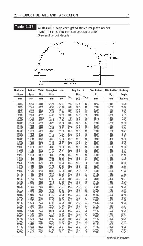
Multi-radius deep corrugated structural plate archesType I: 381 x 140 mm corrugation profileSize and layout details
Maximum Bottom Total Springline Area Required ‘S’ Top Radius Side Radius Re-Entry
Span Span Rise Rise Side Rt Rs Angle
mm mm mm mm m2 (x2) mm mm degrees
9190 9170 4585 4275 34.11 7.0 14.5 36 5730 4230 4.099165 8865 5380 4257 41.10 5.0 17.5 40 6530 4230 15.109420 9385 4690 4294 35.94 8.0 14.5 37 6030 4230 5.319340 9160 5290 4282 41.35 7.0 16.5 40 6330 4230 13.609720 9690 4795 4408 37.85 9.0 14.5 38 6130 4330 5.129760 9475 5595 4479 45.48 7.0 17.5 42 6530 4430 14.3510085 10015 5070 4513 41.84 9.0 15.5 40 6730 4430 7.0610060 9540 5790 4325 49.28 9.0 17.5 44 7630 4230 19.8910400 10385 4655 4349 39.66 10.0 14.5 39 8230 4230 4.0710485 10335 5275 4467 45.92 11.0 15.5 42 7430 4330 10.5910400 10005 5990 4659 51.99 12.0 16.5 45 6330 4530 16.7710690 10675 4770 4470 41.72 11.0 14.5 40 8130 4330 3.8410700 10485 5355 4401 47.94 12.0 15.5 43 7930 4230 12.9210680 10215 6075 4646 54.20 15.0 15.5 46 6430 4430 18.5211000 10920 5030 4431 45.86 13.0 14.5 42 8330 4230 8.0610985 10745 5440 4431 50.01 13.0 15.5 44 8230 4230 13.6911000 10650 6385 4833 58.86 15.0 16.5 48 6630 4630 19.2011225 11130 5140 4497 48.04 12.0 15.5 43 9330 4330 8.3711300 10990 5680 4430 54.41 13.0 16.5 46 9430 4230 16.8011240 10620 6495 4835 61.12 18.0 15.5 49 6630 4530 21.1611580 11500 5230 4622 50.28 13.0 15.5 44 9330 4430 7.7611600 11200 5760 4461 56.69 14.0 16.5 47 9630 4230 17.6711535 10945 6548 4903 63.75 13.0 18.5 50 7930 4730 20.0211900 11685 5450 4493 54.58 15.0 15.5 46 9930 4230 12.9211900 11510 5885 4590 59.22 15.0 16.5 48 9430 4330 17.1911865 11510 6760 5387 67.06 8.0 21.5 51 8530 5330 14.7512140 11950 5575 4647 57.05 14.0 16.5 47 10730 4430 11.9212155 11580 6140 4585 63.72 15.0 17.5 50 10430 4330 20.7312160 11700 7060 5488 72.06 8.0 22.5 53 9130 5430 16.5712455 12110 5835 4618 61.65 16.0 16.5 49 10730 4330 16.0512500 12050 6280 4840 66.73 14.0 18.5 51 10930 4630 17.8612500 11935 7050 5347 74.57 11.0 21.5 54 9730 5230 18.7612770 12535 5960 4899 64.53 13.0 18.5 50 12930 4730 12.7512800 12360 6395 4967 69.48 15.0 18.5 52 10730 4730 17.2812800 12110 7335 5445 79.79 11.0 22.5 56 10430 5330 20.4313090 12870 6120 5096 67.30 16.0 17.5 51 10630 4830 19.2513100 12715 6505 5127 72.33 14.0 19.5 53 11630 4930 11.9013105 12570 7525 5787 83.20 8.0 24.5 57 11530 5730 16.0513330 12890 6310 4890 71.90 16.0 18.5 53 12730 4630 17.5113330 12965 6660 5293 75.21 13.0 20.5 54 12330 5130 17.6013330 12610 7580 5641 85.62 11.0 23.5 58 11130 5530 15.2613640 13020 6320 4711 73.90 19.0 17.5 54 12630 4330 20.3113625 13370 6855 5662 78.49 12.0 21.5 55 11830 5530 21.5113705 13270 7805 6183 89.69 8.0 25.5 59 11130 6130 12.3013950 13505 6490 5055 77.39 18.0 18.5 55 12630 4730 15.1413940 13410 7015 5377 83.33 16.0 20.5 57 12130 5130 17.6114100 13550 8030 5213 95.54 10.0 25.5 61 11430 6130 18.3214205 13755 6660 5193 80.34 19.0 18.5 56 12030 4830 16.9514267 13755 7125 5506 86.37 17.0 20.5 58 11930 5230 17.79
continued on next page
Table 2.32
Top Total
Maximum Bottom Total Springline Area Required ‘S’ Top Radius Side Radius Re-Entrant
Span Span Rise Rise Side Rt Rs Angle
mm mm mm mm m2 (x2) mm mm degrees
14300 13815 8250 6492 98.90 9.0 26.5 62 10730 6430 15.6414540 14185 6780 5438 83.60 18.0 19.5 57 12730 5130 14.9514560 14140 7280 6346 89.77 16.0 21.5 59 12230 5530 15.7114575 13975 8260 5763 101.68 12.0 25.5 63 11130 6230 17.7614808 14361 6938 5463 86.41 23.0 17.5 58 10930 4930 17.1514840 14495 7490 6080 93.26 17.0 21.5 60 11030 5830 13.7914860 14085 8555 6386 107.66 14.0 25.5 65 10930 6230 20.1015155 14915 7085 5919 90.14 18.0 20.5 59 12330 5630 11.7915205 14885 7580 6205 96.49 18.0 21.5 61 11130 5930 13.2415110 14330 8690 6504 111.12 15.0 25.5 66 10730 6330 19.97
Other sizes and plate configurations are available. All dimensions are inside.
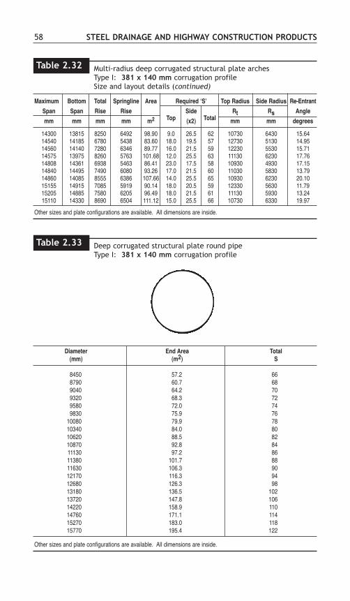
58 STEEL DRAINAGE AND HIGHWAY CONSTRUCTION PRODUCTS
Diameter End Area Total(mm) (m2) S
8450 57.2 668790 60.7 689040 64.2 709320 68.3 729580 72.0 749830 75.9 76
10080 79.9 7810340 84.0 8010620 88.5 8210870 92.8 8411130 97.2 8611380 101.7 8811630 106.3 9012170 116.3 9412680 126.3 9813180 136.5 10213720 147.8 10614220 158.9 11014760 171.1 11415270 183.0 11815770 195.4 122
Other sizes and plate configurations are available. All dimensions are inside.
Multi-radius deep corrugated structural plate archesType I: 381 x 140 mm corrugation profileSize and layout details (continued)
Table 2.32
Top Total
Deep corrugated structural plate round pipeType I: 381 x 140 mm corrugation profile
Table 2.33

2. PRODUCT DETAILS AND FABRICATION 59
Deep corrugated structural plate box culverts Type I: 381 x 140 mm corrugation profileSize and layout details
Crown Haunch Crown Haunch Side SideSpan Rise End Area Angle Angle Radius Radius Length Angle
∆ c ∆ h Rc Rh Dmm mm m2 degrees degrees mm mm mm degrees3170 1180 3.12 7.35 72.36 8820 1016 407 14.003550 1420 4.33 9.97 75.04 8820 1016 559 10.003840 1465 4.94 12.59 77.72 8820 1016 509 6.313965 2210 7.35 9.97 72.36 8820 1016 1423 12.983865 1260 4.18 12.59 72.36 8820 1016 407 10.364105 1860 6.56 12.59 72.36 8820 1016 1017 11.674210 1310 4.76 15.21 72.36 8820 1016 407 9.054735 1960 8.16 17.83 72.36 8820 1016 1017 9.054550 1360 5.36 17.83 72.36 8820 1016 407 7.744890 1610 6.97 20.45 75.02 8820 1016 559 5.064860 2365 10.09 17.83 72.36 8820 1016 1423 9.055155 2420 11.06 20.45 72.36 8820 1016 1423 7.745215 1670 7.72 23.07 75.02 8820 1016 559 3.755360 2075 9.89 23.07 72.36 8820 1016 1017 6.435320 1440 6.62 23.57 69.69 8820 1016 419 8.535445 2480 12.07 23.07 72.36 8820 1016 1423 6.435655 1505 7.33 26.19 69.69 8820 1016 419 7.225955 2645 14.23 27.66 72.36 8820 1016 1473 3.816130 1495 7.83 30.28 72.36 8820 1016 254 2.506165 1900 10.33 30.28 72.36 8820 1016 660 2.506235 2715 15.36 30.28 72.36 8820 1016 1473 2.506320 1645 8.91 31.43 69.69 8820 1016 419 4.606480 1975 11.25 32.90 72.36 8820 1016 660 1.196495 2380 13.89 32.90 72.36 8820 1016 1067 1.19
continued on following page...
Table 2.34
Corrugated Steel Box CulvertsCorrugated steel box culverts approach the rectangular shape of a low, wide box.This is made possible by the addition of special rib plates (where required) to thestandard deep corrugated structural plate sheets (see Figure 2.13). The resultingcombined section develops the flexural capacity required for the very flat top andsharp corners.
The foundation for box culverts can be designed as a conventional concretefooting, steel footer pads (as shown in Figure 2.14), or a full steel invert.
Corrugated steel box culverts can be designed for low, wide waterwayrequirements with heights of cover between 450 mm and 1500 mm (measured fromthe outside crest of the main barrel) and various loading situations.
Box culverts are available in standard spans of 3.170 m to 12.315 m and rises of1.180 m to 3.555 m. Table 2.34 provides representative sizes available. Special sizesare available by contacting the local manufacturer.

60 STEEL DRAINAGE AND HIGHWAY CONSTRUCTION PRODUCTS
Deep corrugated structural plate box culverts Type I: 381 x 140 mm corrugation profileSize and layout details (continued)
Crown Haunch Crown Haunch Side SideSpan Rise End Area Angle Angle Radius Radius Length Angle
∆ c ∆ h Rc Rh Dmm mm m2 degrees degrees mm mm mm degrees6645 1720 9.77 34.05 69.69 8820 1016 419 3.296970 1795 10.67 36.67 69.69 8820 1016 419 1.987000 2200 13.50 36.67 69.69 8820 1016 825 1.987025 2610 16.35 36.67 69.69 8820 1016 1232 1.987290 1875 11.62 39.29 69.69 8820 1016 419 0.677300 2285 14.58 39.29 69.69 8820 1016 825 0.677310 2690 17.56 39.29 69.69 8820 1016 1232 0.677315 3095 20.52 39.29 69.69 8820 1016 1638 0.677405 1680 10.21 39.29 58.98 8820 1016 419 11.387800 1965 12.71 41.91 58.98 8820 1016 622 10.077945 2370 15.87 41.91 58.98 8820 1016 1029 10.078575 1920 13.90 36.45 69.69 11430 1016 419 2.098605 2325 17.38 36.45 69.69 11430 1016 825 2.098635 2735 20.89 36.45 69.69 11430 1016 1232 2.099145 1940 14.64 39.48 64.32 11430 1016 419 5.949225 2345 18.35 39.48 64.32 11430 1016 825 5.949310 2750 22.10 39.48 64.32 11430 1016 1232 5.949810 2105 16.92 43.53 64.32 11430 1016 419 3.929865 2510 20.90 43.53 64.32 11430 1016 825 3.929920 2920 24.92 43.53 64.32 11430 1016 1232 3.9210460 2285 19.43 47.58 64.32 11430 1016 419 1.8910485 2690 23.68 47.58 64.32 11430 1016 825 1.8910515 3100 27.95 47.58 64.32 11430 1016 1232 1.8910895 2355 20.59 50.09 61.64 11430 1016 419 3.3210940 2760 25.02 50.09 61.64 11430 1016 825 3.3210990 3165 29.47 50.09 61.64 11430 1016 1232 3.3211645 2530 23.31 54.67 58.96 11430 1016 419 3.7111700 2935 28.04 54.67 58.96 11430 1016 825 3.7111750 3345 32.81 54.67 58.96 11430 1016 1232 3.7112270 2745 26.46 58.72 58.96 11430 1016 419 1.6812290 3150 31.45 58.72 58.96 11430 1016 825 1.6812315 3555 36.45 58.72 58.96 11430 1016 1232 1.68
Other sizes and plate configurations are available. All dimensions are inside.
Table 2.34
Installation of a Type I deep corrugated structural plate box culvert.

2. PRODUCT DETAILS AND FABRICATION 61
Figure 2.13 Reinforcing rib for deep corrugated structural plate Type I.
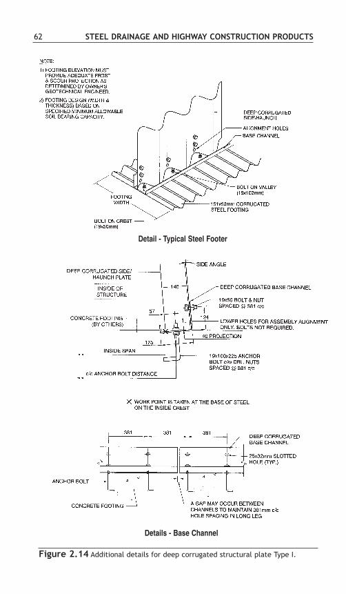
62 STEEL DRAINAGE AND HIGHWAY CONSTRUCTION PRODUCTS
Figure 2.14 Additional details for deep corrugated structural plate Type I.
Detail - Typical Steel Footer
Details - Base Channel

2. PRODUCT DETAILS AND FABRICATION 63
Deep corrugated structural plate box culvert assembled at job site.
Deep corrugated structural plate box culvert on foundation with end walls attached.
DEEP CORRUGATED STRUCTURAL PLATE TYPE II
Product DescriptionDeep corrugated structural plate Type II has a 400 x 150 mm corrugation, which isshown in Figure 2.1.
Standard plates are fabricated in one length and several widths, as shown in Table2.35 and Figure 2.15. The coverage length (excluding the side lips) is 1200 mm. Theplate width designation, H, is used to describe the various plate widths available. His the distance between circumferential bolt holes, or one circumferential bolt holespace (circumferential refers to the direction around the periphery of the structure, atright angles to the length of the structure). For instance, a 9 H plate has a net widthof 9 circumferential bolt hole spaces (see Figure 2.15). The bolt hole space, H, is425 mm.
Plates are furnished curved to various radii and are identified with a permanentmark which shows information such as the plate geometry. This marking is providedto simplify field erection and to make identification of the structure details, in the

64 STEEL DRAINAGE AND HIGHWAY CONSTRUCTION PRODUCTS
Approximate Weight of Galvanized Plates, kg* Number Specified Wall Thickness, mm of
Plate Width AssemblyDesignation 3.0 4.0 5.0 6.0 7.0 Bolts/Plate
3H 57.2 78.4 99.8 121.0 141.2 224H 72.8 99.8 127.0 154.1 179.8 235H 88.5 121.2 154.3 187.1 218.4 246H 104.1 142.7 181.6 220.2 257.0 257H 119.7 164.1 208.8 253.3 295.6 268H 135.4 185.5 236.1 286.3 334.2 279H 151.0 206.9 263.4 319.4 372.8 28
Weight of deep corrugated structural plate sectionsType II: 400 x 150 mm corrugation profile
Table 2.36
Notes 1. Weight of bolts not included.2. Bolt length used for all structures = 51 mm3. Weight of bolts and nuts in kg per hundred = 27.0 kg4. To compute the approximate weight of structures per metre of structure length: (1) multiply the weight from the
table by the number of plates in the periphery having that plate designation (2) multiply the number of boltsfrom the table by the number of plates in the periphery having that plate designation (3) add the two numberstogether (4) divide by 1.2
future, as easy as possible. The plates are available in thickness’ ranging from 3 to7 mm. Weights of individual plate sections are shown in Table 2.36.
Section PropertiesSection properties, used for design, are provided in Table 2.37. Properties of the arc-and-tangent corrugation are derived mathematically using the design thickness. Theproperties in the table include area, moment of inertia, section modulus and radius ofgyration.
Sizes and ShapesThe plates are assembled into various shapes as the single radius arch shapes shownin Table 2.38. Round, two radius arches, special shapes, and other single radius archsizes are also available. Detailed assembly instructions accompany each structure.
Plate Width Net Width, Overall Width,Designation mm mm
3H 1275 15554H 1700 19805H 2125 24056H 2550 28307H 2975 32558H 3400 36809H 3825 4105
H = 425 mm
Deep corrugated structural plate sectionsType II: 400 x 150 mm corrugation profileDetails of uncurved plates
Table 2.35

2. PRODUCT DETAILS AND FABRICATION 65
Figure 2.15 Deep Corrugated Structural Plate Type II plate configuration

Elas
ticPl
astic
Deve
lope
dSp
ecifi
edDe
sign
Tang
ent
Tang
ent
Tang
ent
Area
Neut
ral
Mom
ent
Sect
ion
Radi
us o
fSe
ctio
nW
idth
Thic
knes
sTh
ickn
ess
Leng
thAn
gle
1An
gle
2Ax
isof
Iner
tiaM
odul
usG
yrat
ion
Mod
ulus
Fact
orTL
θθ 1θθ 2
Ay
IS
rZ
WF
mm
mm
mm
degr
ees
degr
ees
mm
2 /m
mm
mm
m4 /
mm
mm
3 /m
mm
mm
m3 /
mm
*
3.0
2.84
114.
2351
.04
29.0
33.
905
80.0
4110
886
136.
0152
.80
184.
161.
375
4.0
3.89
112.
8451
.23
28.8
35.
351
80.5
6314
944
185.
5052
.85
252.
661.
375
5.0
4.95
111.
4251
.44
28.6
36.
811
81.0
9119
060
235.
0452
.90
322.
051.
376
6.0
6.00
110.
0051
.64
28.4
48.
260
81.6
1423
154
283.
7152
.95
391.
011.
377
7.0
7.00
108.
6351
.84
28.2
59.
640
82.1
1227
071
329.
6952
.99
456.
911.
377
*WF
is th
e ra
tio o
f the
flat
pla
te w
idth
to th
e co
rruga
ted
plat
e wi
dth.
Dim
ensio
ns a
re s
ubje
ct to
man
ufac
turin
g to
lera
nces
.
66 STEEL DRAINAGE AND HIGHWAY CONSTRUCTION PRODUCTSD
eep
corr
ugat
ed s
truc
tura
l pl
ate
sect
ions
Type
II:
400
x 1
50 m
mco
rrug
atio
n pr
ofile
Tabl
e 2.
37
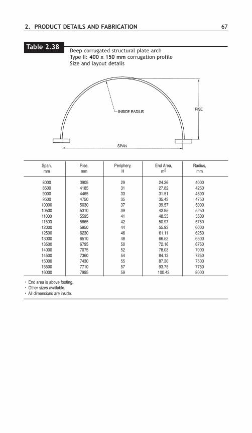
2. PRODUCT DETAILS AND FABRICATION 67
Span, Rise, Periphery, End Area, Radius,mm mm H m2 mm
8000 3905 29 24.36 40008500 4185 31 27.82 42509000 4465 33 31.51 45009500 4750 35 35.43 475010000 5030 37 39.57 500010500 5310 39 43.95 525011000 5595 41 48.55 550011500 5665 42 50.97 575012000 5950 44 55.93 600012500 6230 46 61.11 625013000 6510 48 66.52 650013500 6795 50 72.16 675014000 7075 52 78.03 700014500 7360 54 84.13 725015000 7430 55 87.30 750015500 7710 57 93.75 775016000 7995 59 100.43 8000
• End area is above footing.• Other sizes available.• All dimensions are inside.
Deep corrugated structural plate archType II: 400 x 150 mm corrugation profileSize and layout details
Table 2.38

68 STEEL DRAINAGE AND HIGHWAY CONSTRUCTION PRODUCTS
SECTION C: SPECIFICATIONS
Specifications in Common UseSpecifications are divided into two basic classes – those covering design andconstruction, and those covering materials. Examples of design and constructionspecifications are the AASHTO and ASTM design specifications, and the CanadianHighway Bridge Design Code (CHBDC). Material specifications are published byCSA, AASHTO, ASTM and others. (See Tables 2.39 and 2.40.)
Material Specifications - Historical BackgroundCSA Standard G401 deals with material and fabrication requirements for the fullrange of corrugated steel pipe products currently used in Canada including riveted,helical lock seam, and structural plate pipe. Dimensional data is given for all typesof round pipe and for standard pipe-arch made from corrugated steel pipe.Dimensional data is not provided for the wide variety of shapes available withstructural plate, or for the fittings fabricated from corrugated steel pipe.
The CSA Standard is based on specifications previously prepared by theCorrugated Steel Pipe Institute. In 1970, the Corrugated Steel Pipe Institute firstpublished Specification 501, representing an industry consensus concerning thematerials and methods of fabrication that should be used in manufacturingcorrugated steel pipe. In addition, the specification dealt with workmanship, repair,quality control, inspection and rejection.
In 1974, the Roads and Transportation Association of Canada, under the directionof the Metric Commission of Canada, undertook the task of developing metricstandards for all highway products. As part of the task force, the Ontario Ministry ofTransportation and Communications set up a Unified Drainage Standards Committeeto examine existing standards for all drainage products. In 1978, the CorrugatedSteel Pipe Institute published a revised Specification 501. The document proposednew product standards, predominantly in hard converted metric figures based on therecommendations from the Unified Drainage Standards Committee. It was from thisbackground that the current CSA Standard G401 was developed.
Agency Reference
CSA Canadian Highway Bridge Design Code - Section 7 - Buried Structures - CAN/CSA - S6
AASHTO Standard Specification for Highway Bridges – Division 1, Section 12
AASHTO LRFD Bridge Design Specifications - Section 12
ASTM Standard Practice for Structural Design of Corrugated Steel Pipe, Pipe Arches, and Arches for Stormand Sanitary Sewers and Other Buried Applications - ASTM A796
Design specificationsTable 2.39

2. PRODUCT DETAILS AND FABRICATION 69
Material Description SpecificationsAASHTO ASTM CSA
Zinc Coated Steel base metal* with 610 g/m2 M 218 A 929M G401Sheets & Coils zinc coating
Polymer Coated Polymer coatings applied to sheets* and M 246 A 742M G401Sheets and Coils coils*
Aluminum Steel base metal* coated with 305 g/m2 M 274 A 929M G401Coated Coils of pure aluminum
Aluminum-Zinc Steel base metal* coated with 214 g/m2 M 289 A 929M G401Coated Coils of an aluminum-zinc alloy
Sewer and Corrugated pipe fabricated from any of the aboveDrainage pipe sheets or coils. Pipe is fabricated by corrugating
continuous coils into helical form with lockseam or welded seam, or by rolling annular corrugatedmill sheets and plate, and riveting seams or field bolting seams as appropriate.1. Galvanized corrugated steel pipe M 36M A 760M G4012. Polymeric pre-coated sewer and drainage pipe M 245 A 762M G4013. Aluminized Steel Type 2 corrugated steel pipe M 36M A 760M G4014. Aluminum-Zinc alloy coated corrugated - A 760M G401
steel pipe5. Galvanized spiral rib steel pipe M 36M A 760M G4016. Aluminized Steel Type 2 spiral rib steel pipe M 36M A 760M G401 7. Structural plate pipe M 167 A 761M G401
Asphalt Coated Corrugated steel pipe of any of the types M 190 A 849 G401Steel Sewer Pipe shown above with a 1.3 mm, high purity A 862
asphalt coating
Invert Paved Corrugated steel pipe of any one of the types M 190 A 849 G401Steel Sewer Pipe shown above with an asphalt pavement A 862
poured in the invert to cover the corrugationby 3.2 mm
Fully Lined Steel Corrugated steel pipe of the typesSewer Pipe shown above
With an internal asphalt lining M 190 A 849 G401centrifugally spun in place A 862
Cold Applied Fibrated mastic or coal tar base coatings of M 243 A 849 -Bituminous various viscosities for field or shop coatingCoatings of corrugated pipe or structural plate
Gaskets and 1. Standard 0-ring gaskets - D1056 -Sealants 2. Sponge neoprene sleeve gaskets
3. Gasketing strips, butyl or neoprene - C361 -4. Mastic sealant
*Design yield strength = 230 MPa min.; tensile strength - 310 MPa min.; elongation (50mm) - 20% min.
Material description and specificationsTable 2.40

70 STEEL DRAINAGE AND HIGHWAY CONSTRUCTION PRODUCTS
SECTION D: CSP COUPLING SYSTEMSA variety of pipe joints are available for connecting lengths of corrugated steel pipe.
The most common CSP joint uses a band around the pipe joint. Figure 2.16illustrates what is meant by a band-type coupling.
The standard types of coupling bands are listed in Table 2.41 and shown in Figure2.18. The band is drawn and secured on the pipe by connection devices, as shownin Figure 2.20. The pipe ends may be identical to the rest of the pipe barrel (plainends), or in the case of helical pipe, the pipe ends may be reformed to an annularcorrugation (reformed ends) as shown in Figure 2.17. A variety of gasket types canbe used, according to band type, as shown in Figures 2.18 and 2.19. Table 2.41includes information on the connection devices and the types of gaskets used witheach type of coupling band, and on the type of pipe ends the band type can be usedwith.
Coupling bands for corrugated steel pipeTable 2.41
Fastening Method Gaskets Pipe End Type Used With
Bar, Sleeve HelicalType Of Cross - Bolt Wedge 0 or Annular
Band Section Angles & Strap Lock Ring Strip Mastic Plain Plain Reformed
Universal x x x x x x x xDimple
Corrugated x x x x x x x
Semi- x x x x x x xCorrugated
Flat x x x x x x x x x
Figure 2.16: Typical band coupling for field joints.

2. PRODUCT DETAILS AND FABRICATION 71
Combination dog bone, and rod and lug coupler.
Semi-corrugated coupler installation.

72 STEEL DRAINAGE AND HIGHWAY CONSTRUCTION PRODUCTS
Figure 2.18 Standard CSP band types. Note: When gaskets are required theyare installed with standard CSP band types as shown.
Figure 2.17 Reformed end of helically corrugated pipe.
Reformed Pipe End
O-Ring Sleeve Gasket
Sleeve GasketSleeve Gasketfor Helical
O-Ringfor Annular
Semi-Corrugated Type
Flat Type
Corrugated
Universal Type

Figure 2.19 Standard gaskets for CSP.
2. PRODUCT DETAILS AND FABRICATION 73
Figure 2.20 Standard band connectors for CSP .
Band Angle Connector
Bar & Strap Connector
Wedge Lock Connector
O-Ring Gasket Sleeve Gasket Strip Gasket

74 STEEL DRAINAGE AND HIGHWAY CONSTRUCTION PRODUCTS
Gain in LengthThe nominal length of corrugated pipe and pipe-arch is usually increased at eachcoupling by a maximum amount dependent on the type of coupling. Where exact runlengths are required, such as between manholes or other fixed points, the designershould take this into account and include explicit instructions in the specification.
LeakageWith the exception of aerial sewer or water lines, the exfiltration (or infiltration) ofmoderate amounts of water may not be important. Where more restricted leakage isrequired (or airtightness in the case of ventilation lines), the couplings can besupplemented with gaskets (Figures 2.18 and 2.19).
Special JointsFor unusual conditions, (i.e. high pressure, extreme disjointing forces, threading pipeinside existing pipe, jacking or boring pipe, and deep vertical drop inlets) a varietyof special designs are available or a new special joint may be designed by themanufacturer to meet specific requirements. A variety of special joints are illustratedin Figure 2.21.
A band puller eases installation of coupler.

2. PRODUCT DETAILS AND FABRICATION 75
SECTION E: FITTINGSOne of the benefits of corrugated steel pipe is that it can be easily and economicallyfabricated into an assortment of fittings. Table 2.42 provides minimum dimensionsfor CSP elbows (round pipe). Table 2.43 provides minimum dimensions for CSPtees, crosses, laterals and wyes (round pipe).
Structural plate fittings are shop cut from curved corrugated plates and weldedtogether. These structures are usually assembled and bolted in the shop in a trial fitto assure that all parts mate properly. The parts are then clearly marked for fieldassembly.
Used in stab typejoints for boring andjacking pipe. May bebolted if required
Bolted flanges areattached to pipe ends.
Band is secured byrod around bandconnected by lugs.
Flange Joint Rod & Lug
Open Lap Joint
Internal Type
Figure 2.21 Illustration of various special CSP joints.
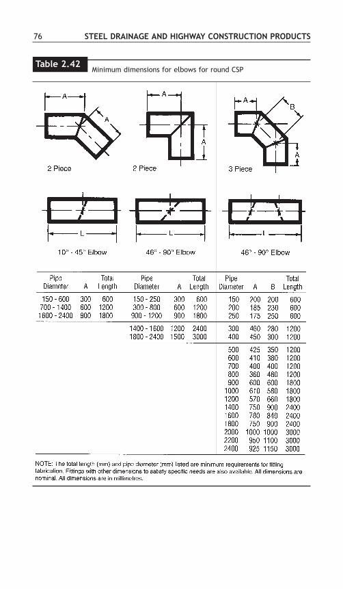
76 STEEL DRAINAGE AND HIGHWAY CONSTRUCTION PRODUCTS
Minimum dimensions for elbows for round CSPTable 2.42
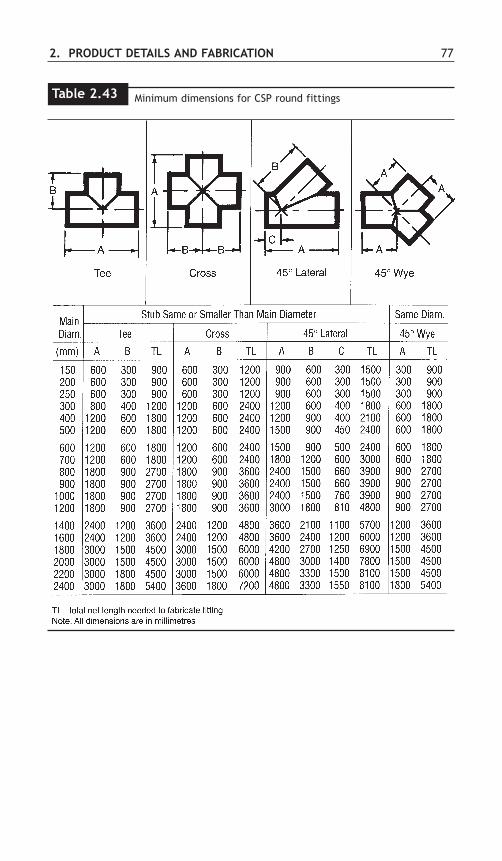
2. PRODUCT DETAILS AND FABRICATION 77
Minimum dimensions for CSP round fittings Table 2.43

Figure 2.22 Saddle branch, bolted to main sewer on the job or at the plant,enables laterals and house connections to join the sewer.
Side view of sewer with saddle branch in place
A
Saddle Plate
Section A-A
A
Saddle BranchSaddle branches are used to connect smaller branch lines to the main line, asillustrated in Figure 2.22. Saddles make it practical to accurately tie in connectionsafter the main line is laid, and new connections can be effectively made on old lines.Saddles can be used to connect almost any type of pipe to a CSP main line. Acommon “universal” type of saddle branch stub to do this is shown in Figure 2.23.
78 STEEL DRAINAGE AND HIGHWAY CONSTRUCTION PRODUCTS
Saddle Plate
Connecting Pipe
Fill Annular Space WithMastic Sealant
Oversize CSP Stub
Figure 2.23 Universal connection detail using saddle branch.
Typical pre-fabricated CSP saddle branch fitting used in connectinghouse laterals or incoming pipe from catch basins.
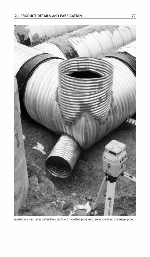
2. PRODUCT DETAILS AND FABRICATION 79
Manhole riser on a detention tank with outlet pipe and groundwater drainage pipe.

80 STEEL DRAINAGE AND HIGHWAY CONSTRUCTION PRODUCTS
Manholes and Catch BasinsManholes and catch basins are available in corrugated pipe construction in two basictypes as shown in Figure 2.24. The riser type of manhole is the simpler of the twoand quite economical. It is only feasible for trunk lines of 900 mm diameter orgreater. When junctions of smaller diameters are involved it is possible to use avertical shaft of larger diameter CSP to connect the sewers. However, when the shaftis greater than 900 mm diameter, reduction details or a special manhole top must beused to suit the manhole cover. Typical reduction details are shown in Figure 2.24.Large diameter manholes or the connection between large diameter trunk lines andthe CSP riser may require reinforcement. Standard catch basin details are illustratedin Figure 2.25.
Trunk Line
Welded Flange for Cover or GradeRing
Smooth Steel Eccentric Reducer
Large DiameterCSP Manhole Junction
Riser Type Manhole
Vertical Shaft Type Manhole
Reduction Details
Figure 2.24 Illustration of types of CSP manholes.

2. PRODUCT DETAILS AND FABRICATION 81
Fabricated riser type CSP manhole.

82 STEEL DRAINAGE AND HIGHWAY CONSTRUCTION PRODUCTS
Figure 2.25 Cross sections of catch basins.
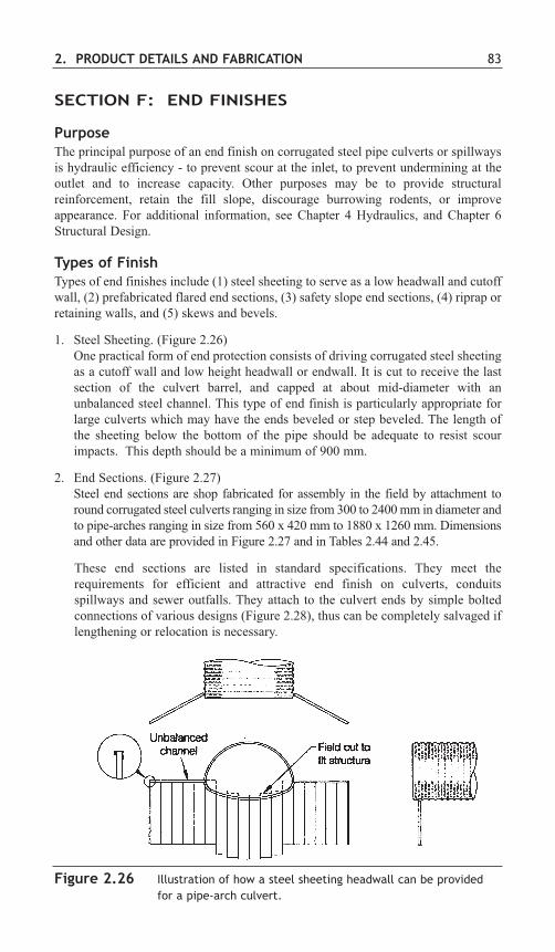
2. PRODUCT DETAILS AND FABRICATION 83
Figure 2.26 Illustration of how a steel sheeting headwall can be providedfor a pipe-arch culvert.
SECTION F: END FINISHES
PurposeThe principal purpose of an end finish on corrugated steel pipe culverts or spillwaysis hydraulic efficiency - to prevent scour at the inlet, to prevent undermining at theoutlet and to increase capacity. Other purposes may be to provide structuralreinforcement, retain the fill slope, discourage burrowing rodents, or improveappearance. For additional information, see Chapter 4 Hydraulics, and Chapter 6Structural Design.
Types of FinishTypes of end finishes include (1) steel sheeting to serve as a low headwall and cutoffwall, (2) prefabricated flared end sections, (3) safety slope end sections, (4) riprap orretaining walls, and (5) skews and bevels.
1. Steel Sheeting. (Figure 2.26) One practical form of end protection consists of driving corrugated steel sheetingas a cutoff wall and low height headwall or endwall. It is cut to receive the lastsection of the culvert barrel, and capped at about mid-diameter with anunbalanced steel channel. This type of end finish is particularly appropriate forlarge culverts which may have the ends beveled or step beveled. The length ofthe sheeting below the bottom of the pipe should be adequate to resist scourimpacts. This depth should be a minimum of 900 mm.
2. End Sections. (Figure 2.27) Steel end sections are shop fabricated for assembly in the field by attachment toround corrugated steel culverts ranging in size from 300 to 2400 mm in diameter andto pipe-arches ranging in size from 560 x 420 mm to 1880 x 1260 mm. Dimensionsand other data are provided in Figure 2.27 and in Tables 2.44 and 2.45.
These end sections are listed in standard specifications. They meet therequirements for efficient and attractive end finish on culverts, conduitsspillways and sewer outfalls. They attach to the culvert ends by simple boltedconnections of various designs (Figure 2.28), thus can be completely salvaged iflengthening or relocation is necessary.

84 STEEL DRAINAGE AND HIGHWAY CONSTRUCTION PRODUCTS
Figure 2.27 Details of end sections in round and pipe-arch shapes.

2. PRODUCT DETAILS AND FABRICATION 85
Dimensions of galvanized steel end sections for pipe-arches68 mm x 13 mm corrugation profile
Table 2.45
Dimensions of galvanized steel end sections for round pipes68 mm x 13 mm corrugation profile
Approximate Dimensions, mm(See Figure 2.27)
GalvanizedPipe Metal A B H L W
Diameter Thickness, min. max. min. ± 50 min. Approximatemm mm Slope Body
300 1.6 125 150 150 535 560 2.25 1 Pc400 1.6 150 200 150 660 710 2.25 1 Pc500 1.6 200 300 150 915 1015 2.125 1 Pc600 1.6 225 330 150 1040 1170 2.125 1 Pc800 2.0 280 405 200 1295 1400 2.125 1 Pc900 2.0 330 485 230 1525 1780 2.0 2 Pc
1000 2.8 380 635 295 1750 2085 2.125 2 Pc1200 2.8 430 740 305 1980 2235 2.0 2 Pc1400 2.8 430 840 305 2135 2540 2.0 2 Pc1600 2.8/3.5 430 915 305 2210 2845 1.875 3 Pc1800 2.8/3.5 430 1120 305 2210 3050 1.5 3 Pc2000 2.8/3.5 430 1220 305 2210 3300 1.375 3 Pc2200 2.8/3.5 430 1320 305 2210 3455 1.333 3 Pc2400 2.8/3.5 430 1475 305 2210 3660 1.125 3 Pc
Approximate Dimensions, mm(See Figure 2.27)
GalvanizedMetal A B H L W
Span x Rise, Thickness, min. max. min. ± 50 min. Approximatemm mm Slope Body
560 x 420 1.6 150 280 150 610 865 2.0 1 Pc680 x 500 1.6 180 405 150 810 1170 2.0 1 Pc910 x 660 2.0 230 405 150 990 1475 1.875 1 Pc1030 x 740 2.0 280 460 180 1170 1855 1.875 1 Pc1150 x 820 2.8 305 535 230 1345 2080 1.75 2 Pc1390 x 970 2.8 405 660 305 1575 2235 1.875 2 Pc1630 x 1120 2.8 430 760 305 1755 2540 1.875 2 Pc1880 x 1260 2.8/3.5 430 915 305 1955 3150 1.625 3 Pc
Notes:1. All 3-piece bodies to have 2.8 mm sides and 3.5 mm center panels. Multiple panel bodies to have lap seams which
are to be tightly joined by galvanized rivets or bolts.2. For 1880 mm x 1260 mm size, reinforced edges to be supplemented with galvanized stiffener angles. The angles
to be attached by galvanized nuts and bolts.3. Galvanized toe plate to be available as an accessory when specified on the order, and will be the same thickness
as the End Section.
Notes:1. All 3-piece bodies to have 2.8 mm sides and 3.5 mm center panels. Multiple panel bodies to have lap seams which
are to be tightly joined by galvanized rivets or bolts.2. For 1600 mm and larger sizes, reinforced edges to be supplemented with galvanized stiffener angles. The angles
to be attached by galvanized nuts and bolts.3. Galvanized toe plate to be available as an accessory when specified on the order, and will be the same thickness
as the End Section.
Table 2.44

86 STEEL DRAINAGE AND HIGHWAY CONSTRUCTION PRODUCTS
Figure 2.28 Details of end section connections for round and pipe-archshapes.
Type #5Available for all Round and Pipe-Arch sizes shown.
(Type 1 and Type 2 connections are recommended forthe smaller sizes with annular ends.)
Type #1Available in sizes 300 mm through 600 mm
Round and 560 x 420 mm through680 x 500 mm Pipe-Arches.
Type #2Available in sizes 800 mm and 900 mm
Round and 910 x 660 mm through1390 x 970 mm Pipe-Arches.
Universal Band Collarbolted to end sectionwith 9.5 mm bolts

2. PRODUCT DETAILS AND FABRICATION 87
3. Safety Slope End Sections, (Figures 2.29, 2.30 and 2.31) Recent data from U.S. state and federally sponsored research studies show thatflatter slopes on roadside embankments greatly minimize the hazard potential tomotorists. Application of this concept, with the design of 4 to 1 and 6 to 1roadside embankments, has contributed significantly to improving the safety ofhighways. The use of safety slope end sections on highway culverts maintains thesafety design of the flattened roadway embankments.
The pre-fabricated safety slope end sections are available with 4 to 1 or 6 to 1slopes and are designed to fit round pipe sizes from 300 mm through 1400 mmand pipe-arch sizes from 450 x 340 mm through 2130 x 1400 mm.
While safety is the primary reason for using safety slope end sections, the taperedflare improves the hydraulic efficiency of the culvert at both the inlet and outletends. A deep skirt anchors the end section while preventing scouring andundercutting. The flat apron or bottom panels eliminate twisting or mis-alignment of the end treatment.
Motorists who encroach on these flattened slopes, defined as recoverable slopes,generally stop their vehicles or slow them enough to return to the roadway safely.When culverts are required on these recoverable slopes they must be madetraversable or present a minimal hazard to an errant vehicle. The preferredtreatment is to match the slope of the culvert with the embankment slope.
On cross drainage structures, a small culvert is defined as a pipe with a 750 mmspan or less. On such small culverts no other treatment is required (See Figure2.29). Single structures with end sections having spans greater than 750 mm canbe made traversable for passenger size vehicles by using safety bars to reduce theclear opening spans (see Figures 2.30 and 2.31). The use of safety bars to makethe safety slope end sections traversable should not decrease the hydrauliccapacity of the culvert.
As referenced by AASHTO, 30 full scale vehicular crash tests have shown thatpassenger size vehicles can traverse cross drainage structures with safety slopeend sections equipped with cross bars (Figure 2.30). The tests showed that, whenbars are spaced on 762 mm centers, automobiles can safely cross at speeds aslow as 30 km/hr and as high as 100 km/hr.
Parallel drainage structures are those oriented parallel to the main flow of traffic.They typically are used under driveways, field entrances, access ramps,intersecting side roads and median crossovers. These culverts present asignificant safety hazard because they can be struck head-on by impactingvehicles. As with cross drains, the end treatments on parallel drains should matchthe traversable slope. Research shows that for parallel drainage structures, safetybars set on 610 mm centers will significantly reduce wheel snagging (Figure2.31).
Safety slope end sections are efficient and provide an attractive end finish oncross and parallel drainage structures. They attach to the culvert end by simplebolted connections and can be completely salvaged if lengthening of thestructure or relocation is required. Dimensions and other data are given in Tables2.46 to 2.48.

Figure 2.31: Parallel drainage safety end section.
88 STEEL DRAINAGE AND HIGHWAY CONSTRUCTION PRODUCTS
Figure 2.29 Safety slope end section.
Figure 2.30: Cross drainage safety end section.

2. PRODUCT DETAILS AND FABRICATION 89
Special fabricated twin end sections.
Equivalent Pipe-Arch Nominal Toe Plate Dimensions (mm) L Dimensions (mm)Diameter Dimensions (mm) Thickness Overall 1:4 Slope 1:6 Slope
(mm) Span Rise (mm) A H W Width Length Length
400 450 340 1.6 200 150 600 1000 560 840500 560 420 1.6 200 150 710 1110 880 1320600 680 500 1.6 200 150 830 1230 1200 1800700 800 580 2.8 300 225 950 1550 1320 1980800 910 660 2.8 300 225 1060 1660 1640 2460900 1030 740 2.8 300 225 1180 1780 1960 29401000 1150 820 2.8 400 300 1300 2100 2280 34201200 1390 970 2.8 400 300 1540 2340 2880 43201400 1630 1120 2.8 400 300 1780 2580 3480 52201600 1880 1260 2.8 400 300 2030 2830 4040 60601800 2130 1400 2.8 400 300 2280 3080 4600 6900
Dimensions of safety end sections for round CSP (See Figure 2.27)Table 2.46
Pipe Nominal Toe Plate Dimensions (mm) L Dimensions (mm)Diameter Thickness Overall 1:4 Slope 1:6 Slope
(mm) (mm) A H W Width Length Length
300 1.6 200 150 450 850 n/a 700400 1.6 200 150 550 950 800 1200450 1.6 200 150 600 1000 1000 1500500 1.6 200 150 650 1050 1200 1800525 1.6 200 150 675 1075 1300 1950600 1.6 200 150 750 1150 1600 2400700 2.8 300 225 850 1450 1800 2700750 2.8 300 225 900 1500 2000 3000800 2.8 300 225 950 1550 2200 3300900 2.8 300 225 1050 1650 2600 39001000 2.8 400 300 1150 1950 3000 45001050 2.8 400 300 1200 2000 3200 48001200 2.8 400 300 1350 2150 3800 57001350 2.8 400 300 1500 2300 4400 66001400 2.8 400 300 1550 2350 4600 6900
Dimensions of safety end sections for CSP pipe-arches (See Figure 2.27)Table 2.47

90 STEEL DRAINAGE AND HIGHWAY CONSTRUCTION PRODUCTS
Equivalent Pipe-Arch Nominal Toe Plate Dimensions (mm) L Dimensions (mm)Diameter Dimensions (mm) Thickness Overall 1:4 Slope 1:6 Slope
(mm) Span Rise (mm) A H W Width Length Length
450 500 390 1.6 200 150 650 1050 760 1140525 580 465 1.6 200 150 730 1130 1060 1590600 660 530 1.6 200 150 810 1210 1320 1980750 830 660 2.8 300 225 980 1580 1640 2460900 1010 790 2.8 300 225 1160 1760 2160 32401050 1160 920 2.8 400 300 1310 2110 2680 40201200 1340 1050 2.8 400 300 1490 2290 3200 48001350 1485 1190 2.8 400 300 1635 2435 3760 56401500 1670 1300 2.8 400 300 1820 2620 4200 63001650 1815 1450 2.8 400 300 1965 2765 4800 7200
Dimensions of safety end sections of spiral rib pipe-arches (See Figure 2.27)Table 2.48
4. Riprap or Retaining Walls.The slope at the end of a culvert (mitered or square cut) can be protectedeconomically against erosion by riprap or retaining walls (see Chapter 13). Stoneriprap may be sealed by portland cement grout or asphaltic concrete. Ageotextile is normally used under riprap to prevent the smaller grained soilbeneath it from washing out.
5. Skews and Bevels. Depending on the structural capability and hydraulic efficiencies desired,corrugated steel pipe and structural plate structures can be designed andmanufactured with square, skewed or beveled ends.
Square, skewed and beveled ends are shown in Figure 2.32. Manufacturers can provideassistance in designing these types of end finishes to meet specific project requirements.
When head walls are not considered in the design, or when skews or beveledends are used, the end treatment (especially of structural plate structures)requires special attention. Incomplete structural rings act as retaining walls, andmust be reinforced or tied back to maintain structural integrity. Both skewed andbeveled ends are usually reinforced as shown in Figure 2.33. Reinforcement ofstructure ends is a desired design practice, regardless of structure size.
Details and essential considerations are discussed in Chapter 6, Structural Design.

2. PRODUCT DETAILS AND FABRICATION 91
Figure 2.32 End type definitions.

92 STEEL DRAINAGE AND HIGHWAY CONSTRUCTION PRODUCTS
Figure 2.33 Concrete end reinforcing collar.
Detail - Concrete Collar

2. PRODUCT DETAILS AND FABRICATION 93
AASHTO, Guide to Standardized Highway Drainage Products, AASHTO-AGC-ARTBA Joint Committee Task Force 13, American Association of State Highwayand Transportation Officials, 444 N. Capitol St., N.W., Ste. 249, Washington, D.C.20001, 2000.
AASHTO, Roadside Design Guide, American Association of State Highway andTransportation Officials, 444 N. Capitol St., N.W., Ste. 249, Washington, D.C.20001, 1996.
AASHTO, “Standard Specification for Corrugated Steel Pipe, Metallic-Coated forSewers and Drains,” M3 6/M3 6M, Standard Specifications for TransportationMaterials and Methods of Sampling and Testing, American Association of StateHighway and Transportation Officials, 444 N. Capitol St., N.W., Ste. 249,Washington, D.C. 20001.
AASHTO, “Standard Specification for Corrugated Steel Structural Plates, ZincCoated, for Field-Bolted Pipe, Pipe Arches, and Arches,” M I 67/M I 67M,Standard Specifications for Transportation Materials and Methods of Sampling andTesting, American Association of State Highway and Transportation Officials, 444N. Capitol St., N.W., Ste. 249, Washington, D.C. 20001.
ASTM, “Standard Specification for Corrugated Steel Pipe, Metallic-Coated forSewers and Drains,” A760/A760M, Annual Book of Standards, Vol. 01.06,American Society for Testing and Materials, I 00 Barr Harbor Drive, PO BoxC700, West Conshohocken, PA 19428-2959.
ASTM, “Standard Specification for Corrugated Steel Structural Plates, ZincCoated, for Field-Bolted Pipe, Pipe Arches, and Arches,” A761/A761M, AnnualBook of Standards, Vol. 01.06, American Society for Testing and Materials, 100Barr Harbor Drive, PO Box C700, West Conshohocken, PA 19428-2959.
ASTM, “Standard Specification for Corrugated Steel Pipe, Polymer Precoated forSewers and Drains,” A762/A762M, Annual Book of Standards, Vol. 01.06,American Society for Testing and Materials, 100 Barr Harbor Drive, PO BoxC700, West Conshohocken, PA 19428-2959.
ASTM, “Standard Practice for Structural design of Corrugated Steel Pipe, Pipe-Arches, and Arches for Storm and Sanitary Sewers and Other BuriedApplications,” A796/A796M, Annual Book of Standards, Vol. 01.06, AmericanSociety for Testing and Materials, 100 Barr Harbor Drive, PO Box C700, WestConshohocken, PA 19428-2959.
ASTM, “Standard Practice for Installing Factory-Made Corrugated Steel Pipe forSewers and Other Applications,” A798/A798M, Annual Book of Standards, Vol.01.06, American Society for Testing and Materials, 100 Barr Harbor Drive, POBox C700, West Conshohocken, PA 19428-2959.
ASTM, “Standard Practice for Installing Steel Structural Plate Pipe for Sewers andOther Applications,” A807/A807M, Annual Book of Standards, Vol. 01.06,
BIBLIOGRAPHY

94 STEEL DRAINAGE AND HIGHWAY CONSTRUCTION PRODUCTS
American Society for Testing and Materials, 100 Barr Harbor Drive, PO BoxC700, West Conshohocken, PA 19428-2959.
ASTM, “Standard Practice for Life-Cycle Cost Analysis of Corrugated Steel PipeUsed for Culverts, Storm Sewers, and Other Buried Applications,” A930, AnnualBook of Standards, Vol. 01.06, American Society for Testing and Materials, 100Barr Harbor Drive, PO Box C700, West Conshohocken, PA 19428-2959.
ASTM, “Standard Specification for Corrugated Steel Box Culverts,” A964/A964M,Annual Book of Standards, Vol. 01.06, American Society for Testing and Materials,100 Barr Harbor Drive, PO Box C700, West Conshohocken, PA 19428-2959.
ASTM, “Standard Practice for Structural Design of Reinforcements for Fittings inFactory-Made Corrugated Steel Pipe for Sewers and Other Applications,”A998/A998M, Annual Book of Standards, Vol. 01.06, American Society for Testingand Materials, 100 Barr Harbor Drive, PO Box C700, West Conshohocken, PA19428-2959.