14lr208e328 (en 300328) v1.8 - blue radios (en 300328) v1.8.pdf · -2 of 62- international...
TRANSCRIPT
Page: 1 of 62
TEST REPORT
of
R&TTE (1999/5/EC) Directive ETSI EN 300 328 V1.8.1: 2012
Product: BT 4.0 Dual Mode Module
Brand: BlueRadios
Model: BR-LE4.0-D2A
Model Difference: N/A
Applicant: BlueRadios, Inc.
Address: 7173 S. Hanava Street, Suite 600, Englewood, CO/USA
Test Performed by: International Standards Laboratory <Lung-Tan LAB> *Address: No. 120, Lane 180, San Ho Tsuen, Hsin Ho Rd. Lung-Tan Hsiang, Tao Yuan County 325, Taiwan *Tel : 886-3-407-1718; Fax: 886-3-407-1738
Report No.: ISL-14LR208E328
Issue Date : 2014/09/10
Test results given in this report apply only to the specific sample(s) tested and are traceable to national or international standard through calibration of the equipment and evaluating measurement uncertainty herein.
This report MUST not be used to claim product endorsement by TAF, NEMKO or any agency of the Government.
This test report shall not be reproduced except in full, without the written approval of International Standards Laboratory.

-2 of 62-
International Standards Laboratory Report Number: ISL-14LR208E328
VERIFICATION OF COMPLIANCE
Applicant: BlueRadios, Inc.
Equipment Under Test: BT 4.0 Dual Mode Module
Brand Name: BlueRadios
Model Number: BR-LE4.0-D2A
Model Different: N/A
Date of Test: 2014/09/01 ~ 2014/09/09
Date of EUT Received: 2014/08/30
APPLICABLE STANDARDS
STANDARD TEST RESULT
ETSI EN 300 328 V1.8.1:2012 Complied
The above equipment was tested by International Standards Laboratory for compliance with the requirements set forth in the European Standard ETSI EN 300 328 V1.8.1: 2012. class I device under R&TTE Directive 1999/5/EC. The results of testing in this report apply to the product/system that was tested only. Other similar equipment will not necessarily produce the same results due to production tolerance and measurement uncertainties.
Test By:
Date: 2014/09/10
Dino Chen / Engineer
Prepared By:
Date: 2014/09/10
Elisa Chen / Specialist
Approved By:
Date: 2014/09/10
Vincent Su / Technical Manager
-3 of 62-
International Standards Laboratory Report Number: ISL-14LR208E328
Version
Version No. Date Description
00 2014/09/10 Initial creation of document

-4 of 62-
International Standards Laboratory Report Number: ISL-14LR208E328
TABLE OF CONTENTS
1. DESCRIPTION OF EQUIPMENT UNDER TEST (EUT) ................................................... 5
2. GENERAL DESCRIPTION OF APPLIED STANDARDS .................................................. 6
3. TEST FACILITY ....................................................................................................................... 6
4. BLOCK DIAGRAM OF TEST SETUP .................................................................................. 7
5. FREQUENCY HOPPING EQUIPMENT MEASUREMENT (FHSS) .............................. 12
6. OTHER TYPES OF WIDE BAND MODULATION EQUIPMENT ................................. 39
APPENDIX A PHOTOGRAPHS OF SET UP ............................................................................. 56
APPENDIX B PHOTOGRAPHS OF EUT ................................................................................... 59

-5 of 62-
International Standards Laboratory Report Number: ISL-14LR208E328
1. DESCRIPTION OF EQUIPMENT UNDER TEST (EUT) General:
Product Name: BT 4.0 Dual Mode Module
Brand Name: BlueRadios
Model Name: BR-LE4.0-D2A
Model Difference: N/A
Power Supply: 3.0Vdc from host
Type of Equipment: Modular
Temperature Range: -20℃ to 55 ℃
Simultaneous transmissions:
No
Hardware Version: N/A
Software Version: N/A
Bluetooth 1Tx, 1Rx:
Bluetooth Version V2.1 + EDR (GFSK + π /4 DQPSK+ 8DPSK)
V4.0(GFSK)
Frequency Range: 2402 – 2480MHz 2402 – 2480MHz
Channel number: 79 channels 40 channels
Modulation type: Frequency Hopping Spread Spectrum (FHSS)
Wide band Modulation
Transmit Power: (EIRP)
9.50dBm 7.40dBm
Dwell Time: <= 0.4s N/A
Operating Mode: Point-to-Point
Adaptive/ Non-Adaptive Adaptive Adaptive
LBT (Listen Before Talk) Yes
■ Adaptive Frequency Hopping using LBT based DAA □ Adaptive Frequency Hopping using other forms of DAA
(non-LBT based) □ Short Control Signaling Transmissions
Occupied Channel Bandwidth
Within 2400-2483.5MHz
Duty Cycle N/A
Antenna Beam forming No
Antenna Designation: Type: Chip Antenna, 2dBi max. P/N:ANT8030-2R4-01A
The EUT is compliance with Bluetooth V2.1 + EDR and V4.0. Remark: The above DUT's information was declared by manufacturer. Please refer to the specifications or user's manual for more detailed description.

-6 of 62-
International Standards Laboratory Report Number: ISL-14LR208E328
1.1. DESCRIPTION OF TEST MODES
The EUT has been tested under Operating condition. To control the EUT for staying in continuous transmitting and receiving mode is programmed. Bluetooth BDR, EDR1, EDR2: Lowest (2402MHz), Mid (2441MHz) and Highest (2480MHz) mode. Bluetooth LE4.0: Lowest (2402MHz), Mid (2442MHz) and Highest (2480MHz) mode. The worst case of Radiated Spurious Emission was report: Bluetooth BDR mode: Lowest (2402MHz) and Highest (2480MHz) mode.
Normal test conditions : Temperature : -20 to ℃ 55 ℃ Relative humidity: 20 % to 75 % Normal Voltage: this modular is powered from 5.0Vdc from USB host. Extreme temperatures and Power source voltage Refer to section 5.1.1.2 of EN 300328 For tests at extreme temperatures, measurements shall be made over the extremes of the operating temperature ranges as declared by the manufacturer. For tests at extreme voltage, measurements shall be made over the extremes of the power source voltage range as declared by the manufacturer.
2. GENERAL DESCRIPTION OF APPLIED STANDARDS
The EUT According to the Specifications, it must comply with the requirements of the following standards: ETSI EN 300 328 V1.8.1 : 2012– Electromagnetic compatibility and Radio spectrum Matters (ERM) ; Wideband transmission systems; Data transmission equipment operating in the 2.4GHz ISM band and using wide band modulation techniques:
3. TEST FACILITY
International Standards Laboratory <Lung-Tan LAB> No. 120, Lane 180, San Ho Tsuen, Hsin Ho Rd., Lung-Tan Hsiang, Tao Yuan County 325, Taiwan A fully anechoic chamber was used for the radiated spurious emissions test. TAF Accreditation Lab. Lab number: 0997 NEMKO Laboratory Authorities No.: ELA 113B
-7 of 62-
International Standards Laboratory Report Number: ISL-14LR208E328
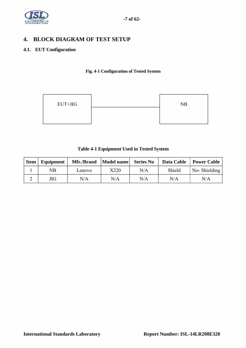
4. BLOCK DIAGRAM OF TEST SETUP
4.1. EUT Configuration
Fig. 4-1 Configuration of Tested System
Table 4-1 Equipment Used in Tested System
Item Equipment Mfr./Brand Model name Series No Data Cable Power Cable
1 NB Lenovo X220 N/A Shield No- Shielding
2 JIG N/A N/A N/A N/A N/A
EUT+JIG NB
-8 of 62-
International Standards Laboratory Report Number: ISL-14LR208E328
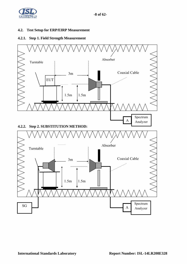
4.2. Test Setup for ERP/EIRP Measurement 4.2.1. Step 1. Field Strength Measurement
4.2.2. Step 2. SUBSTITUTION METHOD:
EUT
3m
1.5m
Coaxial Cable
1.5m
Turntable Absorber
ASpectrum Analyzer
3m
1.5m
Coaxial Cable
1.5m
Turntable Absorber
ASpectrum Analyzer
SG

-9 of 62-
International Standards Laboratory Report Number: ISL-14LR208E328
4.3. Test Setup for Conducted Measurement
4.4. Test Setup for Extreme test
4.5. Test Setup for verifying the adaptivity/receiver blocking of an equipment
Power Meter or SP EUT
Variable AC or DC power supply
Spectrum analyzer / Power meter
EUT
Temperature Chamber
-10 of 62-
International Standards Laboratory Report Number: ISL-14LR208E328
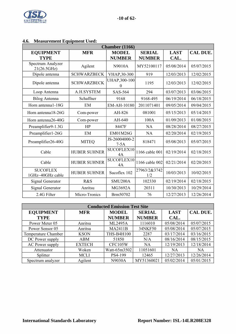
4.6. Measurement Equipment Used:
Chamber (1166) EQUIPMENT
TYPE MFR MODEL
NUMBER SERIAL
NUMBERLAST CAL.
CAL DUE.
Spectrum Analyzer 21(26.5GHz)
Agilent N9010A MY52100117 05/08/2014 05/07/2015
Dipole antenna SCHWARZBECK VHAP,30-300 919 12/03/2013 12/02/2015
Dipole antenna SCHWARZBECKUHAP,300-100
0 1195 12/03/2013 12/02/2015
Loop Antenna A.H.SYSTEM SAS-564 294 03/07/2013 03/06/2015
Bilog Antenna Schaffner 9168 9168-495 06/19/2014 06/18/2015
Horn antenna1-18G EM EM-AH-10180 2011071401 09/05/2014 09/04/2015
Horn antenna18-26G Com-power AH-826 081001 05/15/2013 05/14/2015
Horn antenna26-40G Com-power AH-640 100A 01/09/2013 01/08/2015
Preamplifier9-1.3G HP 8447F NA 08/28/2014 08/27/2015
Preamplifier1-26G EM EM01M26G NA 02/20/2014 02/19/2015
Preamplifier26-40G MITEQ JS-26004000-2
7-5A 818471 05/08/2013 05/07/2015
Cable HUBER SUHNERSUCOFLEX10
4A 1166 cable 001 02/19/2014 02/18/2015
Cable HUBER SUHNERSUCOFLEX10
4A 1166 cable 002 02/21/2014 02/20/2015
SUCOFLEX 1GHz~40GHz cable
HUBER SUHNER Sucoflex 10227963/2&3742
1/2 10/03/2013 10/02/2015
Signal Generator R&S SMU200A 102330 02/19/2014 02/18/2015
Signal Generator Anritsu MG3692A 20311 10/30/2013 10/29/2014
2.4G Filter Micro-Tronics Brm50702 76 12/27/2013 12/26/2014
Conducted Emission Test Site
EQUIPMENT TYPE
MFR MODEL NUMBER
SERIAL NUMBER
LAST CAL.
CAL DUE.
Power Meter 05 Anritsu ML2495A 1116010 05/08/2014 05/07/2015Power Sensor 05 Anritsu MA2411B 34NKF50 05/08/2014 05/07/2015
Temperature Chamber KSON THS-B4H100 2287 03/17/2014 03/16/2015DC Power supply ABM 51850 N/A 08/16/2014 08/15/2015AC Power supply EXTECH CFC105W NA 12/19/2013 12/18/2014
Attenuator Woken Watt-65m3502 11051601 NA NA Splitter MCLI PS4-199 12465 12/27/2013 12/26/2014
Spectrum analyzer Agilent N9030A MY51360021 05/02/2014 05/01/2015
-11 of 62-
International Standards Laboratory Report Number: ISL-14LR208E328
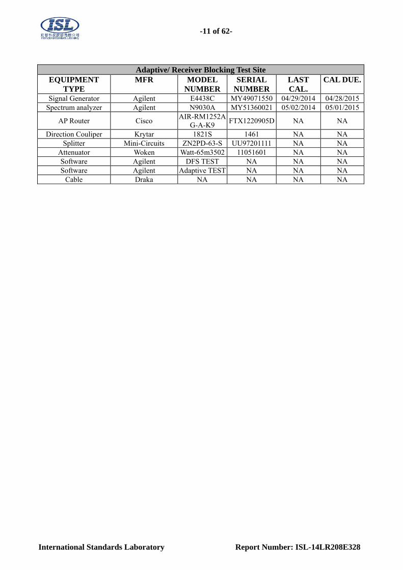
Adaptive/ Receiver Blocking Test Site
EQUIPMENT TYPE
MFR MODEL NUMBER
SERIAL NUMBER
LAST CAL.
CAL DUE.
Signal Generator Agilent E4438C MY49071550 04/29/2014 04/28/2015Spectrum analyzer Agilent N9030A MY51360021 05/02/2014 05/01/2015
AP Router Cisco AIR-RM1252A
G-A-K9 FTX1220905D NA NA
Direction Couliper Krytar 1821S 1461 NA NA Splitter Mini-Circuits ZN2PD-63-S UU97201111 NA NA
Attenuator Woken Watt-65m3502 11051601 NA NA Software Agilent DFS TEST NA NA NA Software Agilent Adaptive TEST NA NA NA
Cable Draka NA NA NA NA
-12 of 62-
International Standards Laboratory Report Number: ISL-14LR208E328
5. Frequency Hopping Equipment Measurement (FHSS)
5.1. ETSI EN 300 328 SUB-CLAUSE 4.3.1.1 RF Output Power This requirement applies to all types of Frequency Hopping equipment
5.1.1. Limit: The maximum RF output power for adaptive Frequency Hopping equipment shall be equal to or less than 20 dBm. The maximum RF output power for non-adaptive Frequency Hopping equipment, shall be declared by the supplier. The maximum RF output power for this equipment shall be equal to or less than the value declared by the supplier. This declared value shall be equal to or less than 20 dBm. This limit shall apply for any combination of power level and intended antenna assembly.
5.1.2. Test Procedure: See Sub-Clause 5.3.2.1 of ETSI EN 300 328 for the test conditions See Sub-Clause 5.3.2.2.1.1 of ETSI EN 300 328 for conducted method.
-13 of 62-
International Standards Laboratory Report Number: ISL-14LR208E328
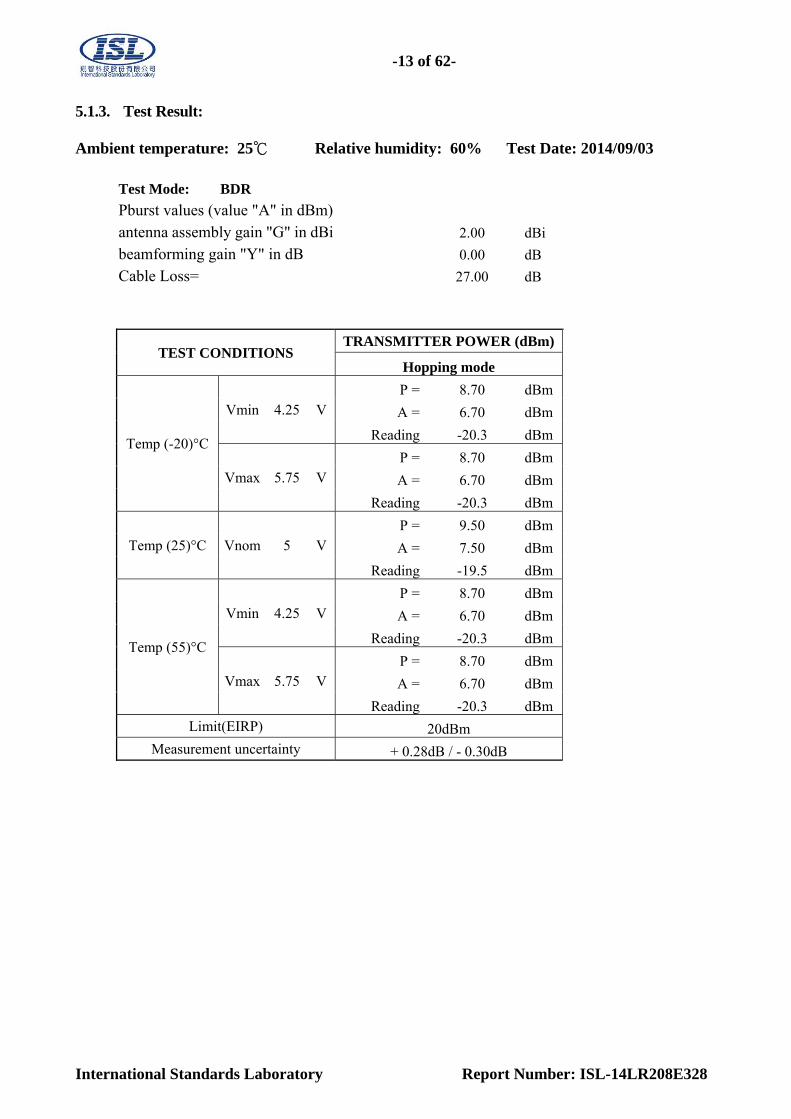
5.1.3. Test Result: Ambient temperature: 25℃ Relative humidity: 60% Test Date: 2014/09/03
Test Mode: BDR
Pburst values (value "A" in dBm)antenna assembly gain "G" in dBi 2.00 dBi
beamforming gain "Y" in dB 0.00 dB
Cable Loss= 27.00 dB
TEST CONDITIONS TRANSMITTER POWER (dBm)
Hopping mode
Temp (-20)°C
Vmin 4.25 V P = 8.70 dBm
A = 6.70 dBm
Reading -20.3 dBm
Vmax 5.75 V P = 8.70 dBm
A = 6.70 dBm
Reading -20.3 dBm
Temp (25)°C Vnom 5 V P = 9.50 dBm
A = 7.50 dBm
Reading -19.5 dBm
Temp (55)°C
Vmin 4.25 V P = 8.70 dBm
A = 6.70 dBm
Reading -20.3 dBm
Vmax 5.75 V P = 8.70 dBm
A = 6.70 dBm
Reading -20.3 dBmLimit(EIRP) 20dBm
Measurement uncertainty + 0.28dB / - 0.30dB

-14 of 62-
International Standards Laboratory Report Number: ISL-14LR208E328
Ambient temperature: 25℃ Relative humidity: 60% Test Date: 2014/09/03
Test Mode: EDR 1M
Pburst values (value "A" in dBm) antenna assembly gain "G" in dBi 2.00 dBi
beamforming gain "Y" in dB 0.00 dB
Cable Loss= 27.00 dB
TEST CONDITIONS TRANSMITTER POWER (dBm)
Hopping mode
Temp (-20)°C
Vmin 4.25 VP = 7.40 dBm
A = 5.40 dBm
Reading -21.6 dBm
Vmax 5.75 VP = 7.40 dBm
A = 5.40 dBm
Reading -21.6 dBm
Temp (25)°C Vnom 5 VP = 7.00 dBm
A = 5.00 dBm
Reading -22 dBm
Temp (55)°C
Vmin 4.25 VP = 5.90 dBm
A = 3.90 dBm
Reading -23.1 dBm
Vmax 5.75 VP = 5.90 dBm
A = 3.90 dBm
Reading -23.1 dBm Limit(EIRP) 20dBm
Measurement uncertainty + 0.28dB / - 0.30dB
-15 of 62-
International Standards Laboratory Report Number: ISL-14LR208E328
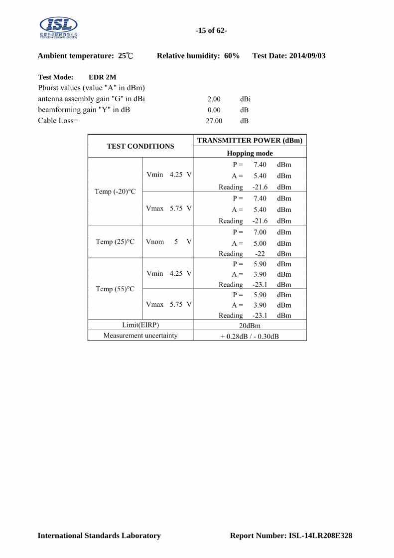
Ambient temperature: 25℃ Relative humidity: 60% Test Date: 2014/09/03
Test Mode: EDR 2M
Pburst values (value "A" in dBm) antenna assembly gain "G" in dBi 2.00 dBi
beamforming gain "Y" in dB 0.00 dB
Cable Loss= 27.00 dB
TEST CONDITIONS TRANSMITTER POWER (dBm)
Hopping mode
Temp (-20)°C
Vmin 4.25 VP = 7.40 dBm
A = 5.40 dBm
Reading -21.6 dBm
Vmax 5.75 VP = 7.40 dBm
A = 5.40 dBm
Reading -21.6 dBm
Temp (25)°C Vnom 5 VP = 7.00 dBm
A = 5.00 dBm
Reading -22 dBm
Temp (55)°C
Vmin 4.25 VP = 5.90 dBm
A = 3.90 dBm
Reading -23.1 dBm
Vmax 5.75 VP = 5.90 dBm
A = 3.90 dBm
Reading -23.1 dBm Limit(EIRP) 20dBm
Measurement uncertainty + 0.28dB / - 0.30dB

-16 of 62-
International Standards Laboratory Report Number: ISL-14LR208E328
5.2. ETSI EN 300 328 SUB-CLAUSE 4.3.1.2 Duty Cycle, Tx-sequence, Tx-gap These requirements apply to non-adaptive frequency hopping equipment or to adaptive frequency hopping equipment operating in a non-adaptive mode. These requirements do not apply for equipment with a maximum declared RF Output power of less than 10 dBm e.i.r.p. or for equipment when operating in a mode where the RF Output power is less than 10 dBm e.i.r.p. Medical devices requiring reverse compatibility with other medical devices placed on the market when earlier versions of the present document were harmonised, are allowed to have an operating mode in which they do not have to comply with the requirements for Duty Cycle, Tx-sequence and Tx-gap. 5.2.1. Limit: For non-adaptive FHSS equipment, the Duty Cycle shall be equal to or less than the maximum value declared by the supplier. In addition, the maximum Tx-sequence time shall be 5 ms while the minimum Tx-gap time shall be 5 ms.
5.2.2. Test Procedure:
See Sub-Clause 5.3.2.1 of ETSI EN 300 328 for the test conditions
See Sub-Clause 5.3.2.2.1.2 of ETSI EN 300 328 for conducted method.
5.2.3. Test Result:
N/A, This is adaptive device.

-17 of 62-
International Standards Laboratory Report Number: ISL-14LR208E328
5.3. ETSI EN 300 328 SUB-CLAUSE 4.3.1.3 Dwell Time, Minimum Frequency Occupation and
Hopping Sequence
These requirements apply to all types of frequency hopping equipment
5.3.1. Limit: Non-adaptive frequency hopping systems The accumulated Dwell Time on any hopping frequency shall not be greater than 15 ms within any period of 15 ms multiplied by the minimum number of hopping frequencies (N) that have to be used. Non-adaptive medical devices requiring reverse compatibility with other medical devices placed on the market when earlier versions of the present document were harmonised, are allowed to have an operating mode in which the maximum dwell time is 400 ms. The hopping sequence(s) shall contain at least N hopping frequencies where N is 15 or 15 divided by the minimum Hopping Frequency Separation in MHz, whichever is the greater. The Minimum Frequency Occupation Time shall be equal to one dwell time within a period not exceeding four times the product of the dwell time per hop and the number of hopping frequencies in use. Adaptive frequency hopping systems Adaptive Frequency Hopping systems shall be capable of operating over a minimum of 70 % of the band specified in clause 1. The maximum accumulated dwell time on any hopping frequency shall be 400 ms within any period of 400 ms multiplied by the minimum number of hopping frequencies (N) that have to be used. The hopping sequence(s) shall contain at least N hopping frequencies at all times, where N is 15 or 15 divided by the minimum Hopping Frequency Separation in MHz, whichever is the greater. The Minimum Frequency Occupation Time shall be equal to one dwell time within a period not exceeding four times the product of the dwell time per hop and the number of hopping frequencies in use. Other Requirements Frequency Hopping equipment shall transmit on a minimum of two hopping frequencies. For non-Adaptive Frequency Hopping equipment, when not transmitting on a hopping frequency, the equipment has to occupy that frequency for the duration of the typical dwell time. For Adaptive Frequency Hopping systems using LBT based DAA, if a signal is detected during the CCA, these systems may jump immediately to the next frequency in the hopping sequence (see clause 4.3.1.6.1.2 point 2) provided the limit for maximum dwell is respected. 5.3.2. Test Procedure: See Sub-Clause 5.3.4.1 of ETSI EN 300 328 for the test conditions See Sub-Clause 5.3.4.2.1 of ETSI EN 300 328 for conducted method.

-18 of 62-
International Standards Laboratory Report Number: ISL-14LR208E328
5.3.3. Test Result:
Dwell Time:
Test Mode: Bluetooth BDR
Ambient temperature: 25℃ Relative humidity: 60% Test Date: 2014/09/04
Type of packet
Maximum dwell time recorded during a
single hop (ms) DH1 0.384 DH3 1.635 DH5 2.860
Packet DH1

-19 of 62-
International Standards Laboratory Report Number: ISL-14LR208E328
Packet DH3
Packet DH5
-20 of 62-
International Standards Laboratory Report Number: ISL-14LR208E328
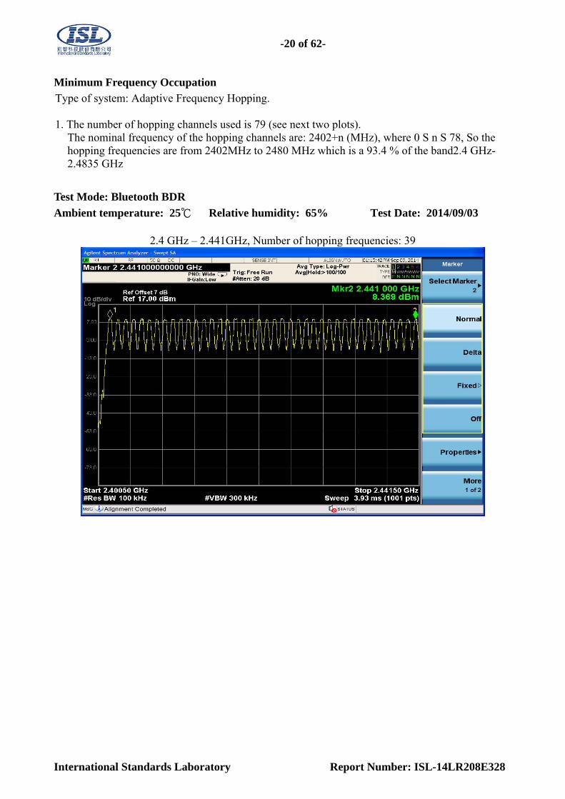
Minimum Frequency Occupation
Type of system: Adaptive Frequency Hopping. 1. The number of hopping channels used is 79 (see next two plots).
The nominal frequency of the hopping channels are: 2402+n (MHz), where 0 S n S 78, So the hopping frequencies are from 2402MHz to 2480 MHz which is a 93.4 % of the band2.4 GHz- 2.4835 GHz
Test Mode: Bluetooth BDR
Ambient temperature: 25℃ Relative humidity: 65% Test Date: 2014/09/03
2.4 GHz – 2.441GHz, Number of hopping frequencies: 39
-21 of 62-
International Standards Laboratory Report Number: ISL-14LR208E328
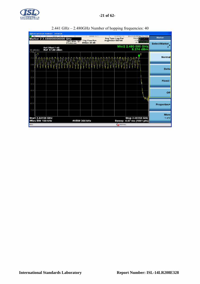
2.441 GHz – 2.480GHz Number of hopping frequencies: 40
-22 of 62-
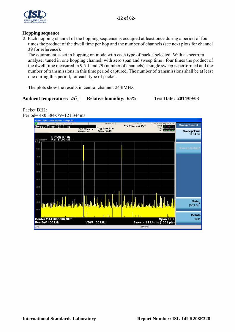
International Standards Laboratory Report Number: ISL-14LR208E328
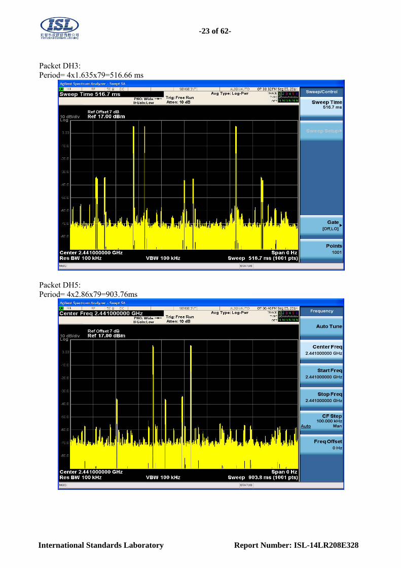
Hopping sequence 2. Each hopping channel of the hopping sequence is occupied at least once during a period of four
times the product of the dwell time per hop and the number of channels (see next plots for channel 39 for reference): The equipment is set in hopping on mode with each type of packet selected. With a spectrum analyzer tuned in one hopping channel, with zero span and sweep time : four times the product of the dwell time measured in 9.5.1 and 79 (number of channels) a single sweep is performed and the number of transmissions in this time period captured. The number of transmissions shall be at least one during this period, for each type of packet.
The plots show the results in central channel: 244lMHz.
Ambient temperature: 25℃ Relative humidity: 65% Test Date: 2014/09/03
Packet DH1: Period= 4x0.384x79=121.344ms
-23 of 62-
International Standards Laboratory Report Number: ISL-14LR208E328
Packet DH3: Period= 4x1.635x79=516.66 ms
Packet DH5: Period= 4x2.86x79=903.76ms

-24 of 62-
International Standards Laboratory Report Number: ISL-14LR208E328
5.4. ETSI EN 300 328 SUB-CLAUSE 4.3.1.4 Hopping Frequency Separation
This requirement applies to all types of frequency hopping equipment.
5.4.1. Limit: Non-adaptive frequency hopping systems The minimum Hopping Frequency Separation shall be equal to Occupied Channel Bandwidth (see clause 4.3.1.7) of a single hop, with a minimum separation of 100 kHz. Adaptive frequency hopping systems
The minimum Hopping Frequency Separation shall be 100 kHz.
5.4.2. Test Procedure: See Sub-Clause 5.3.5.1 of ETSI EN 300 328 for the test conditions See Sub-Clause 5.3.5.2.1 of ETSI EN 300 328 for conducted method.
5.4.3. Test Result: Ambient temperature: 25℃ Relative humidity: 65% Test Date: 2014/09/04
Test Mode Frequency Separation (MHz) Result BDR mode 1.000 PASS
EDR 2M Mode 1.000 PASS EDR 3Mode 1.000 PASS
Channel separation between carries =1.0 MHz
Measurement uncertainty: 120 kHz

-25 of 62-
International Standards Laboratory Report Number: ISL-14LR208E328
5.5. ETSI EN 300 328 SUB-CLAUSE 4.3.1.5 Medium Utilisation (MU) factor This requirement does not apply to adaptive equipment unless operating in a non-adaptive mode. In addition, this requirement does not apply for equipment with a maximum declared RF Output power level of less than 10 dBm e.i.r.p. or for equipment when operating in a mode where the RF Output power is less than 10 dBm e.i.r.p. Medical devices requiring reverse compatibility with other medical devices placed on the market when earlier versions of the present document were harmonised, are allowed to have an operating mode in which they have a Medium Utilisation above the limit defined in clause 4.3.1.5.2. 5.5.1. Limit:
The maximum Medium Utilisation factor for non-adaptive Frequency Hopping equipment shall be
10 %. The Medium Utilisation (MU) factor is a measure to quantify the amount of resources (Power
and Time) used by non-adaptive equipment. The Medium Utilisation factor is defined by the formula:
MU = (P/100 mW) × DC, where: MU is Medium Utilisation factor in %.
P is the RF output power as defined in clause 4.3.1.1.1 expressed in mW.
DC is the Duty Cycle as defined in clause 4.3.1.2.1 expressed in %.
5.5.2. Test Procedure:
See Sub-Clause 5.3.2.1 of ETSI EN 300 328 for the test conditions
See Sub-Clause 5.3.2.2.1.3 of ETSI EN 300 328 for conducted method.
5.5.3. Test Result:
N/A, this is adaptive device and RF Output power level is less than 10 dBm e.i.r.p.

-26 of 62-
International Standards Laboratory Report Number: ISL-14LR208E328
5.6. ETSI EN 300 328 SUB-CLAUSE 4.3.1.6 Adaptivity (Adaptive Frequency Hopping) This requirement does not apply to non-adaptive equipment or adaptive equipment operating in a non-adaptive mode providing the equipment complies with the requirements and/or restrictions applicable to non-adaptive equipment. In addition, this requirement does not apply for equipment with a maximum declared RF Output power level of less than 10 dBm e.i.r.p. or for equipment when operating in a mode where the RF Output power is less than 10 dBm e.i.r.p. Adaptive Frequency Hopping equipment is allowed to operate in a non-adaptive mode providing it complies with the requirements applicable to non-adaptive frequency hopping equipment. Adaptive Frequency Hopping equipment is allowed to have Short Control Signalling Transmissions (e.g. ACK/NACK signals, etc.) without sensing the frequency for the presence of other signals. See clause 4.3.1.6.3. Adaptive Frequency Hopping (AFH) equipment uses a Detect And Avoid (DAA) mechanism which allows an equipment to adapt to its environment by identifying frequencies that are being used by other equipment. Adaptive Frequency Hopping systems shall implement either of the DAA mechanisms provided in clauses 4.3.1.6.1 or 4.3.1.6.2. NOTE: Adaptive systems are allowed to switch dynamically between different adaptive modes.
5.6.1. Limit:
ETSI EN 300 328 SUB-CLAUSE 4.3.1.6.1 Adaptive Frequency Hopping using LBT based DAA The CCA observation time shall be not less than 0,2 % of the Channel Occupancy Time with a minimum of 20 μs. The Channel Occupancy Time for a given hopping frequency, which starts immediately after a successful CCA, shall be less than 60 ms followed by an Idle Period of minimum 5 % of the Channel Occupancy Time with a minimum of 100 μs.
ETSI EN 300 328 SUB-CLAUSE 4.3.1.6.2 Adaptive Frequency Hopping using other forms of
DAA (non-LBT based) The Channel Occupancy Time for a given hopping frequency shall be less than 40 ms. For equipment using a dwell time > 40 ms that want to have other transmissions during the same hop (dwell time) an Idle Period (no transmissions) of minimum 5 % of the Channel Occupancy Period with a minimum of 100 μs shall be implemented. After this, the procedure as in step 1 need to be repeated before having new transmissions on this hopping frequency during the same dwell time.
ETSI EN 300 328 SUB-CLAUSE 4.3.1.6.3 Short Control Signalling Transmissions Adaptive equipment may or may not have Short Control Signalling Transmissions If implemented, Short Control Signalling Transmissions shall have a maximum duty cycle of 10 % within an observation period of 50 ms or within an observation period equal to the dwell time, whichever is the shorter.

-27 of 62-
International Standards Laboratory Report Number: ISL-14LR208E328
5.6.2. Test Procedure:
See Sub-Clause 5.3.7.1 of ETSI EN 300 328 for the test conditions
See Sub-Clause 5.3.7.2.1 of ETSI EN 300 328 for conducted method.
5.6.3. Test Result:
N/A, the RF Output power level is less than 10 dBm e.i.r.p

-28 of 62-
International Standards Laboratory Report Number: ISL-14LR208E328
5.7. ETSI EN 300 328 SUB-CLAUSE 4.3.1.7 Occupied Channel Bandwidth
This requirement applies to all types of frequency hopping equipment
5.7.1. Limit: The Occupied Channel Bandwidth for each hopping frequency shall fall completely within the band given in clause 1. For non-adaptive Frequency Hopping equipment with e.i.r.p greater than 10 dBm, the Occupied Channel Bandwidth for every occupied hopping frequency shall be equal to or less than the value declared by the supplier. This declared value shall not be greater than 5 MHz.
5.7.2. Test Procedure:
See Sub-Clause 5.3.8.1 of ETSI EN 300 328 for the test conditions
See Sub-Clause 5.3.8.2.1 of ETSI EN 300 328 for conducted method.

-29 of 62-
International Standards Laboratory Report Number: ISL-14LR208E328
5.7.3. Test Result: Ambient temperature: 25℃ Relative humidity: 60% Test Date: 2014/09/03
BDR antenna assembly gain "G" in dBi 2.00 dBi
beamforming gain "Y" in dB 0.00 dB
Cable Loss= 27.00 dB
Occupied Channel Bandwidth Channel Low Channel High
Occupied Bandwidth (MHz) 0.835 0.845 Frequency Range(MHz) 2401.6000 2480.4400
Limit 2400.0000 MHz 2483.5000 MHz Measurement Uncertainty +/- 120kHz
EDR 2M antenna assembly gain "G" in dBi 2.00 dBi
beamforming gain "Y" in dB 0.00 dB
Cable Loss= 27.00 dB
Occupied Channel Bandwidth Channel Low Channel High
Occupied Bandwidth (MHz) 1.192 1.196 Frequency Range(MHz) 2401.4200 2480.6400
Limit 2400.0000 MHz 2483.5000 MHz Measurement Uncertainty +/- 120kHz
EDR 3M antenna assembly gain "G" in dBi 2.00 dBi
beamforming gain "Y" in dB 0.00 dB
Cable Loss= 27.00 dB
Occupied Channel Bandwidth Channel Low Channel High
Occupied Bandwidth (MHz) 1.21 1.20 Frequency Range(MHz) 2401.4000 2480.6200
Limit 2400.0000 MHz 2483.5000 MHz Measurement Uncertainty +/- 120kHz

-30 of 62-
International Standards Laboratory Report Number: ISL-14LR208E328
5.8. ETSI EN 300 328 SUB-CLAUSE 4.3.1.8 Transmitter Unwanted Emissions in the out-of-band
Domain
This requirement applies to all types of frequency hopping equipment
5.8.1. Limit: The transmitter unwanted emissions in the out-of-band domain but outside the allocated band, shall not exceed the values provided by the mask in figure 1. NOTE: Within the 2 400 MHz to 2 483,5 MHz band, the Out-of-band emissions are fulfilled by compliance with the Occupied Channel Bandwidth requirement in clause 4.3.1.7.
Transmit mask
5.8.2. Test Procedure: Conducted test method
See Sub-Clause 5.3.9.1 of ETSI EN 300 328 for the test conditions
See Sub-Clause 5.3.9.2.1 of ETSI EN 300 328 for conducted method.
5.8.3. Test Result:
Refer to next page for details.

-31 of 62-
International Standards Laboratory Report Number: ISL-14LR208E328
Test Mode: Bluetooth BDR
Ambient temperature: 25℃ Relative humidity: 60% Test Date: 2014/09/03
out of band domin emission
Test condition 2400 ~
2400-BW 2400 ~
2400-2BW 2483.5 ~
2483.5+BW 2483.5 ~
2483.5+2BW
Temp (-20)°C Vmin 4.25 V -16.01 -30.11 -30.27 -40.14 Vmax 5.75 V -16.03 -30.14 -30.28 -40.16
Temp (25)°C Vnom 5 V -16.11 -30.32 -30.57 -40.48
Temp (55)°C Vmin 4.25 V -16.14 -30.58 -30.61 -40.68 Vmax 5.75 V -16.13 -30.56 -30.63 -40.65
Limit(dBm/MHz) -10 -20 -10 -20
Test Mode: Bluetooth EDR 1
Ambient temperature: 25℃ Relative humidity: 60% Test Date: 2014/09/03
out of band domin emission
Test condition 2400 ~
2400-BW 2400 ~
2400-2BW 2483.5 ~
2483.5+BW 2483.5 ~
2483.5+2BW
Temp (-20)°C Vmin 4.25 V -15.98 -30.14 -30.21 -40.12 Vmax 5.75 V -15.97 -30.18 -30.22 -40.15
Temp (25)°C Vnom 5 V -16.09 -30.34 -30.65 -40.46
Temp (55)°C Vmin 4.25 V -16.04 -30.7 -30.88 -40.57 Vmax 5.75 V -16.07 -30.65 -30.85 -40.55
Limit(dBm/MHz) -10 -20 -10 -20
Test Mode: Bluetooth EDR 2
Ambient temperature: 25℃ Relative humidity: 60% Test Date: 2014/09/03
out of band domin emission
Test condition 2400 ~
2400-BW 2400 ~
2400-2BW 2483.5 ~
2483.5+BW 2483.5 ~
2483.5+2BW
Temp (-20)°C Vmin 4.25 V -16.08 -30.25 -30.27 -40.21 Vmax 5.75 V -16.07 -30.24 -30.26 -40.19
Temp (25)°C Vnom 5 V -16.11 -30.28 -30.66 -40.51
Temp (70)°C Vmin 4.25 V -16.32 -30.37 -30.68 -40.77 Vmax 5.75 V -16.33 -30.39 -30.65 -40.75
Limit(dBm/MHz) -10 -20 -10 -20
-32 of 62-
International Standards Laboratory Report Number: ISL-14LR208E328
5.9. ETSI EN 300 328 SUB-CLAUSE 4.3.1.9 Transmitter Unwanted Emissions in the Spurious
Domain
This requirement applies to all types of frequency hopping equipment.
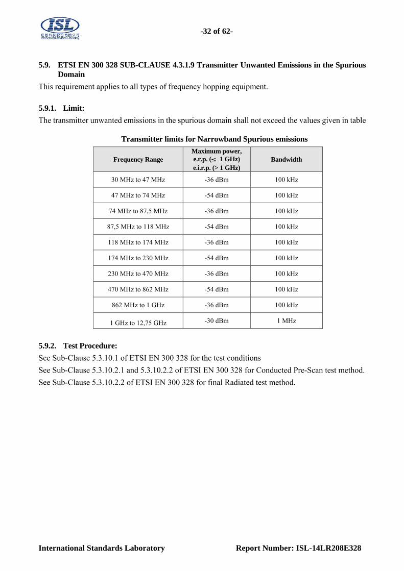
5.9.1. Limit:
The transmitter unwanted emissions in the spurious domain shall not exceed the values given in table
Transmitter limits for Narrowband Spurious emissions
Frequency Range Maximum power, e.r.p. (≤ 1 GHz) e.i.r.p. (> 1 GHz)
Bandwidth
30 MHz to 47 MHz -36 dBm 100 kHz
47 MHz to 74 MHz -54 dBm 100 kHz
74 MHz to 87,5 MHz -36 dBm 100 kHz
87,5 MHz to 118 MHz -54 dBm 100 kHz
118 MHz to 174 MHz -36 dBm 100 kHz
174 MHz to 230 MHz -54 dBm 100 kHz
230 MHz to 470 MHz -36 dBm 100 kHz
470 MHz to 862 MHz -54 dBm 100 kHz
862 MHz to 1 GHz -36 dBm 100 kHz
1 GHz to 12,75 GHz -30 dBm 1 MHz
5.9.2. Test Procedure:
See Sub-Clause 5.3.10.1 of ETSI EN 300 328 for the test conditions
See Sub-Clause 5.3.10.2.1 and 5.3.10.2.2 of ETSI EN 300 328 for Conducted Pre-Scan test method.
See Sub-Clause 5.3.10.2.2 of ETSI EN 300 328 for final Radiated test method.
-33 of 62-
International Standards Laboratory Report Number: ISL-14LR208E328
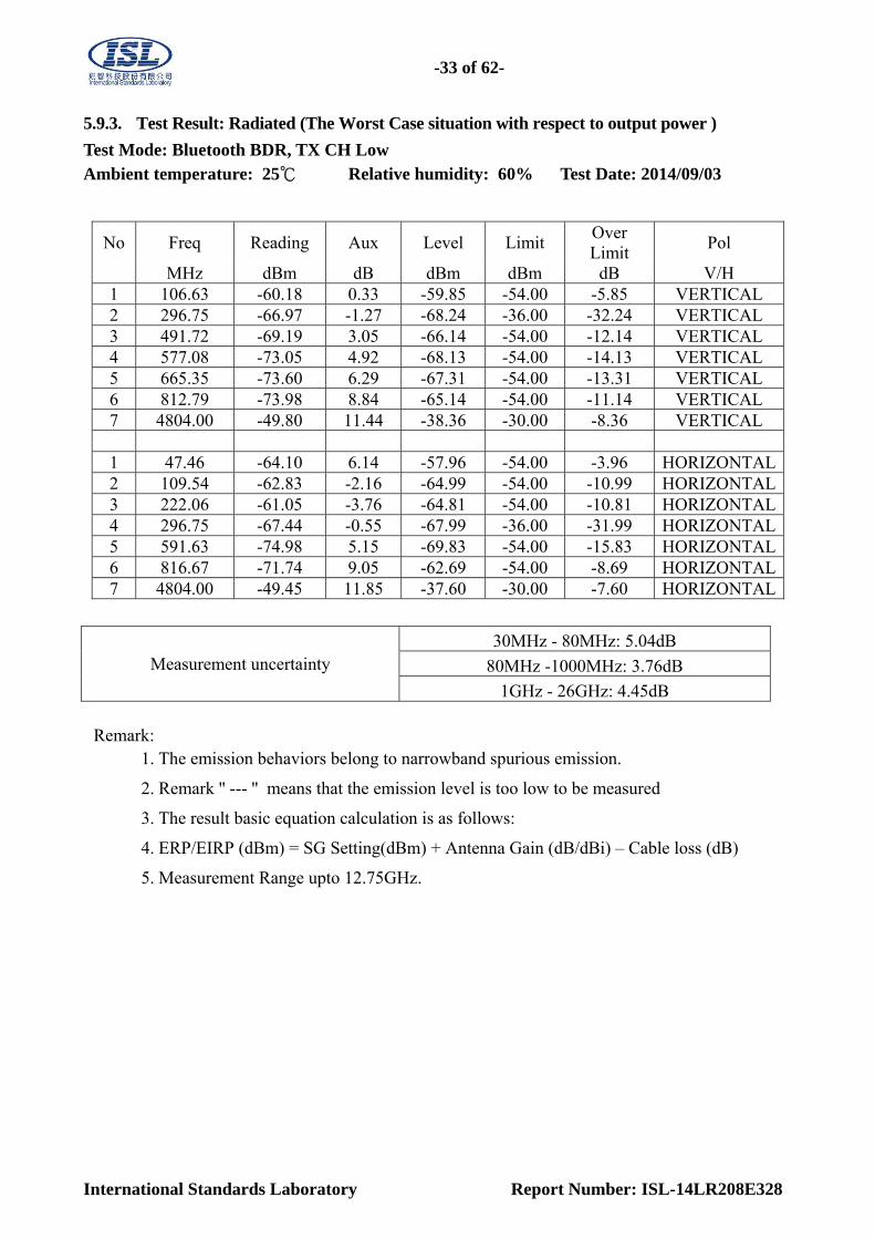
5.9.3. Test Result: Radiated (The Worst Case situation with respect to output power )
Test Mode: Bluetooth BDR, TX CH Low Ambient temperature: 25℃ Relative humidity: 60% Test Date: 2014/09/03
No Freq Reading Aux Level Limit Over Limit
Pol
MHz dBm dB dBm dBm dB V/H 1 106.63 -60.18 0.33 -59.85 -54.00 -5.85 VERTICAL 2 296.75 -66.97 -1.27 -68.24 -36.00 -32.24 VERTICAL 3 491.72 -69.19 3.05 -66.14 -54.00 -12.14 VERTICAL 4 577.08 -73.05 4.92 -68.13 -54.00 -14.13 VERTICAL 5 665.35 -73.60 6.29 -67.31 -54.00 -13.31 VERTICAL 6 812.79 -73.98 8.84 -65.14 -54.00 -11.14 VERTICAL 7 4804.00 -49.80 11.44 -38.36 -30.00 -8.36 VERTICAL 1 47.46 -64.10 6.14 -57.96 -54.00 -3.96 HORIZONTAL2 109.54 -62.83 -2.16 -64.99 -54.00 -10.99 HORIZONTAL3 222.06 -61.05 -3.76 -64.81 -54.00 -10.81 HORIZONTAL4 296.75 -67.44 -0.55 -67.99 -36.00 -31.99 HORIZONTAL5 591.63 -74.98 5.15 -69.83 -54.00 -15.83 HORIZONTAL6 816.67 -71.74 9.05 -62.69 -54.00 -8.69 HORIZONTAL7 4804.00 -49.45 11.85 -37.60 -30.00 -7.60 HORIZONTAL
Measurement uncertainty 30MHz - 80MHz: 5.04dB
80MHz -1000MHz: 3.76dB
1GHz - 26GHz: 4.45dB
Remark: 1. The emission behaviors belong to narrowband spurious emission.
2. Remark '' --- '' means that the emission level is too low to be measured
3. The result basic equation calculation is as follows:
4. ERP/EIRP (dBm) = SG Setting(dBm) + Antenna Gain (dB/dBi) – Cable loss (dB)
5. Measurement Range upto 12.75GHz.

-34 of 62-
International Standards Laboratory Report Number: ISL-14LR208E328
Test Mode: Bluetooth BDR, TX CH High
Ambient temperature: 25℃ Relative humidity: 60% Test Date: 2014/09/03
No Freq Reading Aux Level Limit Over Limit
Pol
MHz dBm dB dBm dBm dB V/H 1 47.46 -66.49 6.15 -60.34 -54.00 -6.34 VERTICAL 2 106.63 -61.15 0.33 -60.82 -54.00 -6.82 VERTICAL 3 295.78 -64.55 -1.28 -65.83 -36.00 -29.83 VERTICAL 4 504.33 -68.40 3.30 -65.10 -54.00 -11.10 VERTICAL 5 576.11 -72.61 4.90 -67.71 -54.00 -13.71 VERTICAL 6 813.76 -75.97 8.87 -67.10 -54.00 -13.10 VERTICAL 7 4960.00 -50.75 12.11 -38.64 -30.00 -8.64 VERTICAL 1 47.46 -64.55 6.14 -58.41 -54.00 -4.41 HORIZONTAL2 109.54 -62.30 -2.16 -64.46 -54.00 -10.46 HORIZONTAL3 222.06 -63.12 -3.76 -66.88 -54.00 -12.88 HORIZONTAL4 296.75 -66.05 -0.55 -66.60 -36.00 -30.60 HORIZONTAL5 594.54 -75.14 5.18 -69.96 -54.00 -15.96 HORIZONTAL6 816.67 -71.02 9.05 -61.97 -54.00 -7.97 HORIZONTAL7 4960.00 -49.40 12.47 -36.93 -30.00 -6.93 HORIZONTAL
Measurement uncertainty 30MHz - 80MHz: 5.04dB
80MHz -1000MHz: 3.76dB
1GHz - 26GHz: 4.45dB
Remark: 1. The emission behaviors belong to narrowband spurious emission.
2. Remark '' --- '' means that the emission level is too low to be measured
3. The result basic equation calculation is as follows:
4. ERP/EIRP (dBm) = SG Setting(dBm) + Antenna Gain (dB/dBi) – Cable loss (dB)
5. Measurement Range upto 12.75GHz.
-35 of 62-
International Standards Laboratory Report Number: ISL-14LR208E328
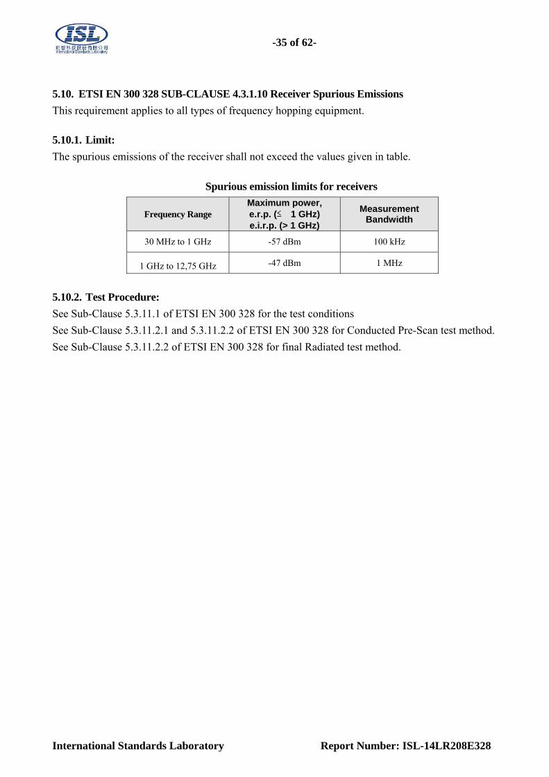
5.10. ETSI EN 300 328 SUB-CLAUSE 4.3.1.10 Receiver Spurious Emissions
This requirement applies to all types of frequency hopping equipment.
5.10.1. Limit:
The spurious emissions of the receiver shall not exceed the values given in table.
Spurious emission limits for receivers
Frequency Range Maximum power, e.r.p. (≤ 1 GHz) e.i.r.p. (> 1 GHz)
Measurement Bandwidth
30 MHz to 1 GHz -57 dBm 100 kHz
1 GHz to 12,75 GHz -47 dBm 1 MHz
5.10.2. Test Procedure:
See Sub-Clause 5.3.11.1 of ETSI EN 300 328 for the test conditions
See Sub-Clause 5.3.11.2.1 and 5.3.11.2.2 of ETSI EN 300 328 for Conducted Pre-Scan test method.
See Sub-Clause 5.3.11.2.2 of ETSI EN 300 328 for final Radiated test method.

-36 of 62-
International Standards Laboratory Report Number: ISL-14LR208E328
5.10.3. Test Result
Test Mode: Bluetooth BDR, RX CH Low
Ambient temperature: 25℃ Relative humidity: 60% Test Date: 2014/09/03
No Freq Reading Aux Level Limit Over Limit
Pol
MHz dBm dB dBm dBm dB V/H 1 106.63 -65.59 0.33 -65.26 -57.00 -8.26 VERTICAL 2 143.49 -67.61 -1.30 -68.91 -57.00 -11.91 VERTICAL 3 296.75 -68.12 -1.27 -69.39 -57.00 -12.39 VERTICAL 4 504.33 -68.24 3.30 -64.94 -57.00 -7.94 VERTICAL 5 785.63 -73.06 8.06 -65.00 -57.00 -8.00 VERTICAL 6 850.62 -78.67 10.19 -68.48 -57.00 -11.48 VERTICAL 7 2036.00 -65.68 0.19 -65.49 -47.00 -18.49 VERTICAL 1 47.46 -69.40 6.14 -63.26 -57.00 -6.26 HORIZONTAL2 185.20 -62.64 -3.49 -66.13 -57.00 -9.13 HORIZONTAL3 296.75 -65.17 -0.55 -65.72 -57.00 -8.72 HORIZONTAL4 455.83 -71.40 2.36 -69.04 -57.00 -12.04 HORIZONTAL5 665.35 -78.00 6.27 -71.73 -57.00 -14.73 HORIZONTAL6 813.76 -72.70 8.94 -63.76 -57.00 -6.76 HORIZONTAL7 3037.00 -67.19 3.57 -63.62 -47.00 -16.62 HORIZONTAL
Measurement uncertainty 30MHz - 80MHz: 5.04dB
80MHz -1000MHz: 3.76dB
1GHz - 26GHz: 4.45dB
Remark: 1. The emission behaviors belong to narrowband spurious emission.
2. Remark '' --- '' means that the emission level is too low to be measured
3. The result basic equation calculation is as follows:
4. ERP/EIRP (dBm) = SG Setting(dBm) + Antenna Gain (dB/dBi) – Cable loss (dB)
5. Measurement Range upto 12.75GHz.

-37 of 62-
International Standards Laboratory Report Number: ISL-14LR208E328
Test Mode: Bluetooth BDR, RX CH High
Ambient temperature: 25℃ Relative humidity: 60% Test Date: 2014/09/03
No Freq Reading Aux Level Limit Over Limit
Pol
MHz dBm dB dBm dBm dB V/H 1 106.63 -65.09 0.33 -64.76 -57.00 -7.76 VERTICAL 2 296.75 -68.63 -1.27 -69.90 -57.00 -12.90 VERTICAL 3 491.72 -67.57 3.05 -64.52 -57.00 -7.52 VERTICAL 4 577.08 -72.22 4.92 -67.30 -57.00 -10.30 VERTICAL 5 794.36 -72.91 8.24 -64.67 -57.00 -7.67 VERTICAL 6 866.14 -76.59 10.31 -66.28 -57.00 -9.28 VERTICAL 7 1994.00 -61.79 0.04 -61.75 -47.00 -14.75 VERTICAL 1 111.48 -60.43 -2.06 -62.49 -57.00 -5.49 HORIZONTAL2 223.03 -61.68 -3.72 -65.40 -57.00 -8.40 HORIZONTAL3 295.78 -65.15 -0.59 -65.74 -57.00 -8.74 HORIZONTAL4 455.83 -72.24 2.36 -69.88 -57.00 -12.88 HORIZONTAL5 593.57 -74.97 5.17 -69.80 -57.00 -12.80 HORIZONTAL6 813.76 -73.33 8.94 -64.39 -57.00 -7.39 HORIZONTAL7 2379.00 -66.61 1.55 -65.06 -47.00 -18.06 HORIZONTAL
Measurement uncertainty 30MHz - 80MHz: 5.04dB
80MHz -1000MHz: 3.76dB
1GHz - 26GHz: 4.45dB
Remark: 1. The emission behaviors belong to narrowband spurious emission.
2. Remark '' --- '' means that the emission level is too low to be measured
3. The result basic equation calculation is as follows:
4. ERP/EIRP (dBm) = SG Setting(dBm) + Antenna Gain (dB/dBi) – Cable loss (dB)
5. Measurement Range upto 12.75GHz.

-38 of 62-
International Standards Laboratory Report Number: ISL-14LR208E328
5.11. ETSI EN 300 328 SUB-CLAUSE 4.3.1.11 Receiver Blocking This requirement does not apply to non-adaptive equipment or adaptive equipment operating in a non-adaptive mode. In addition, this requirement does not apply for equipment with a maximum declared RF Output power level of less than 10 dBm e.i.r.p. or for equipment when operating in a mode where the RF Output power is less than 10 dBm e.i.r.p.
5.11.1. Limit: Adaptive Frequency Hopping equipment shall comply with the requirements defined in clauses 4.3.1.6.1 (LBT based DAA) or 4.3.1.6.2 (non-LBT based DAA) in the presence of a blocking signal with characteristics as provided in table 3.
5.11.2. Test Procedure:
See Sub-Clause 5.3.7.1 of ETSI EN 300 328 for the test conditions
See Sub-Clause 5.3.7.2.1 of ETSI EN 300 328 for conducted method.
5.11.3. Test Result:
N/A, the RF Output power level is less than 10 dBm e.i.r.p

-39 of 62-
International Standards Laboratory Report Number: ISL-14LR208E328
6. Other Types of Wide Band Modulation Equipment
6.1. ETSI EN 300 328 SUB-CLAUSE 4.3.2.1 RF Output Power
This requirement applies to all types of equipment using wide band modulations other than FHSS. 6.1.1. Limit: For adaptive equipment using wide band modulations other than FHSS, the maximum RF output power shall be 20 dBm. The maximum RF output power for non-adaptive equipment shall be declared by the supplier and shall not exceed 20 dBm. See clause 5.3.1 m). For non-adaptive equipment using wide band modulations other than FHSS, the maximum RF output power shall be equal to or less than the value declared by the supplier.
This limit shall apply for any combination of power level and intended antenna assembly. 6.1.2. Test Procedure:
See Sub-Clause 5.3.2.1 of ETSI EN 300 328 for the test conditions
See Sub-Clause 5.3.2.2.1.1 of ETSI EN 300 328 for conducted method.
-40 of 62-
International Standards Laboratory Report Number: ISL-14LR208E328
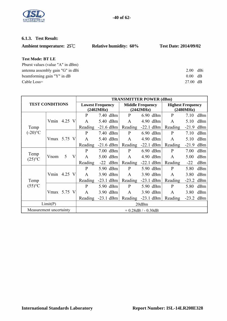
6.1.3. Test Result:
Ambient temperature: 25℃ Relative humidity: 60% Test Date: 2014/09/02
Test Mode: BT LE Pburst values (value "A" in dBm) antenna assembly gain "G" in dBi 2.00 dBi beamforming gain "Y" in dB 0.00 dB Cable Loss= 27.00 dB
TEST CONDITIONS TRANSMITTER POWER (dBm)
Lowest Frequency (2402MHz)
Middle Frequency (2442MHz)
Highest Frequency (2480MHz)
Temp (-20)°C
Vmin 4.25 V P 7.40 dBm P 6.90 dBm P 7.10 dBmA 5.40 dBm A 4.90 dBm A 5.10 dBm
Reading -21.6 dBm Reading -22.1 dBm Reading -21.9 dBm
Vmax 5.75 V P 7.40 dBm P 6.90 dBm P 7.10 dBmA 5.40 dBm A 4.90 dBm A 5.10 dBm
Reading -21.6 dBm Reading -22.1 dBm Reading -21.9 dBm
Temp (25)°C
Vnom 5 V P 7.00 dBm P 6.90 dBm P 7.00 dBmA 5.00 dBm A 4.90 dBm A 5.00 dBm
Reading -22 dBm Reading -22.1 dBm Reading -22 dBm
Temp (55)°C
Vmin 4.25 V P 5.90 dBm P 5.90 dBm P 5.80 dBmA 3.90 dBm A 3.90 dBm A 3.80 dBm
Reading -23.1 dBm Reading -23.1 dBm Reading -23.2 dBm
Vmax 5.75 V P 5.90 dBm P 5.90 dBm P 5.80 dBmA 3.90 dBm A 3.90 dBm A 3.80 dBm
Reading -23.1 dBm Reading -23.1 dBm Reading -23.2 dBmLimit(P) 20dBm
Measurement uncertainty + 0.28dB / - 0.30dB

-41 of 62-
International Standards Laboratory Report Number: ISL-14LR208E328
6.2. ETSI EN 300 328 SUB-CLAUSE 4.3.2.2 Power Spectral Density
This requirement applies to all types of equipment using wide band modulations other than FHSS. 6.2.1. Limit: For equipment using wide band modulations other than FHSS, the maximum Power Spectral Density is limited to 10 dBm per MHz. 6.2.2. Test Procedure:
See Sub-Clause 5.3.3.1 of ETSI EN 300 328 for the test conditions
See Sub-Clause 5.3.3.2.1 of ETSI EN 300 328 for conducted method. 6.2.3. Test Result:
Ambient temperature: 25℃ Relative humidity: 60% Test Date: 2014/09/02
Test Mode: BT LE measured power density Reading (value "A" in dBm) antenna assembly gain "G" in dBi 2.00 dBi
beamforming gain "Y" in dB 0.00 dB
Cable Loss= 0.50 dB
Maximum Power Spectrum Density =A+G+Y
TEST CONDITIONS
Power Density Measurement
Ch Low dBm/1MHz
Ch Mid dBm/1MHz
Ch High dBm/1MHz
Measured power density Reading
0.45 -1.01 -0.89
Maximum Power Spectrum Density
2.95 1.49 1.61
Limit 10 dBm/1MHz
Measurement Uncertainty + 1.5dB/ - 1.4dB

-42 of 62-
International Standards Laboratory Report Number: ISL-14LR208E328
6.3. ETSI EN 300 328 SUB-CLAUSE 4.3.2.3 Duty Cycle, Tx-sequence, Tx-gap These requirements apply to non-adaptive equipment or to adaptive equipment when operating in a non-adaptive mode. The equipment is using wide band modulations other than FHSS. These requirements do not apply for equipment with a maximum declared RF Output power level of less than 10 dBm e.i.r.p. or for equipment when operating in a mode where the RF Output power is less than 10 dBm e.i.r.p. Medical devices requiring reverse compatibility with other medical devices placed on the market when earlier versions of the present document were harmonised, are allowed to have an operating mode in which they do not have to comply with the requirements for Duty Cycle, Tx-sequence and Tx-gap. 6.3.1. Limit: The Duty Cycle shall be equal to or less than the maximum value declared by the supplier. The maximum Tx-sequence Time and the minimum Tx-gap Time shall be according to the formula below: Maximum Tx-Sequence Time = Minimum Tx-gap Time = M
where M is in the range of 3,5 ms to 10 ms. 6.3.2. Test Procedure:
See Sub-Clause 5.3.2.1 of ETSI EN 300 328 for the test conditions
See Sub-Clause 5.3.2.2.1.2 of ETSI EN 300 328 for conducted method. 6.3.3. Test Result:
N/A, Output power is less than 10 dBm e.i.r.p.
-43 of 62-
International Standards Laboratory Report Number: ISL-14LR208E328
6.4. ETSI EN 300 328 SUB-CLAUSE 4.3.2.4 Medium Utilisation (MU) factor This requirement does not apply to adaptive equipment unless operating in a non-adaptive mode. In addition, this requirement does not apply for equipment with a maximum declared RF Output power level of less than 10 dBm e.i.r.p. or for equipment when operating in a mode where the RF Output power is less than 10 dBm e.i.r.p. Medical devices requiring reverse compatibility with other medical devices placed on the market when earlier versions of the present document were harmonised, are allowed to have an operating mode in which they have a Medium Utilisation above the limit defined in clause 4.3.2.4.2. 6.4.1. Limit: For non-adaptive equipment using wide band modulations other than FHSS, the maximum Medium Utilisation factor shall be 10 %.
The Medium Utilisation (MU) factor is a measure to quantify the amount of resources (Power and
Time) used by non-adaptive equipment. The Medium Utilisation factor is defined by the formula:
MU = (P/100 mW) × DC, where: MU is Medium Utilisation factor in %.
P is the RF output power as defined in clause 4.3.1.1.1 expressed in mW.
DC is the Duty Cycle as defined in clause 4.3.1.2.1 expressed in %. 6.4.2. Test Procedure:
See Sub-Clause 5.3.2.1 of ETSI EN 300 328 for the test conditions
See Sub-Clause 5.3.2.2.1.3 of ETSI EN 300 328 for conducted method. 6.4.3. Test Result:
N/A, Output power is less than 10 dBm e.i.r.p.
-44 of 62-
International Standards Laboratory Report Number: ISL-14LR208E328
6.5. ETSI EN 300 328 SUB-CLAUSE 4.3.2.5 Adaptivity (Adaptive Equipment Using Modulations
Other Than FHSS)
This requirement does not apply to non-adaptive equipment or adaptive equipment operating in a non-adaptive mode providing the equipment complies with the requirements and/or restrictions applicable to non-adaptive equipment. In addition, this requirement does not apply for equipment with a maximum declared RF Output power level of less than 10 dBm e.i.r.p. or for equipment when operating in a mode where the RF Output power is less than 10 dBm e.i.r.p. Adaptive equipment using modulations other than FHSS is allowed to operate in a non-adaptive mode providing it complies with the requirements applicable to non-adaptive equipment. An adaptive equipment using modulations other than FHSS is equipment that uses a mechanism by which it can adapt to its environment by identifying other transmissions present within its Occupied Channel Bandwidth. Adaptive equipment using modulations other than FHSS shall implement either of the Detect and Avoid mechanisms provided in clauses 4.3.2.5.1 or 4.3.2.5.2.
Adaptive systems are allowed to switch dynamically between different adaptive modes. 6.5.1. Limit:
ETSI EN 300 328 SUB-CLAUSE 4.3.2.5.1 Non-LBT based Detect and Avoid
Channel Occupancy Time shall be less than 40ms.
Idle Period (no transmissions) of minimum 5 % of the Channel Occupancy Time with a minimum of
100 μs.
ETSI EN 300 328 SUB-CLAUSE 4.3.2.5.2 LBT based Detect and Avoid The present document defines 2 types of adaptive equipment using wide band modulations other than FHSS and that uses an LBT based Detect and Avoid mechanism: Frame Based Equipment and Load Based Equipment Adaptive equipment which is capable of operating as either Load Based Equipment or as Frame Based Equipment is allowed to switch dynamically between these types of operation.
ETSI EN 300 328 SUB-CLAUSE 4.3.2.5.2.2.1 Frame Based Equipment Clear Channel Assessment (CCA) observation time which shall be not less than 20 μs. The Channel Occupancy Time shall be in the range 1 ms to 10 ms followed by an Idle Period of at least 5 % of the Channel Occupancy Time used in the equipment for the current Fixed Frame Period.
-45 of 62-
International Standards Laboratory Report Number: ISL-14LR208E328
ETSI EN 300 328 SUB-CLAUSE 4.3.2.5.2.2.2 Load Based Equipment Clear Channel Assessment (CCA) observation time which shall be not less than 20 μs. If the equipment finds the channel occupied, it shall not transmit on this channel (see note 1). The equipment shall perform an Extended CCA check in which the channel is observed for the duration of a random factor R multiplied by the CCA observation time. R defines the number of clear idle slots resulting in a total Idle Period that needs to be observed before initiation of the transmission. The value of R shall be randomly selected in the range 1…q every time an Extended CCA is required and the value stored in a counter. The value of q is selected by the manufacturer in the range 4…32. This selected value shall be declared by the manufacturer (see clause 5.3.1 d). The counter is decremented every time a CCA slot is considered to be 'unoccupied'. When the counter reaches zero, the equipment may transmit. ; Channel Occupancy Time shall be less than (13/32) × q ms, with q is selected by the manufacturer in the range 4…32, after which the device shall perform the Extended CCA.
ETSI EN 300 328 SUB-CLAUSE 4.3.2.5.3 Short Control Signaling Transmissions Adaptive equipment may or may not have Short Control Signaling Transmissions If implemented, Short Control Signaling Transmissions of adaptive equipment using wide band modulations other than FHSS shall have a maximum duty cycle of 10 % within an observation period of 50 ms. 6.5.2. Test Procedure:
See Sub-Clause 5.3.7.1 of ETSI EN 300 328 for the test conditions
See Sub-Clause 5.3.7.2.1.3 of ETSI EN 300 328 for conducted method. TL= -70dBm/MHz + 20 –Pout e.i.r.p 6.5.3. Test Result: N/A, Output power is less than 10 dBm e.i.r.p.
-46 of 62-
International Standards Laboratory Report Number: ISL-14LR208E328
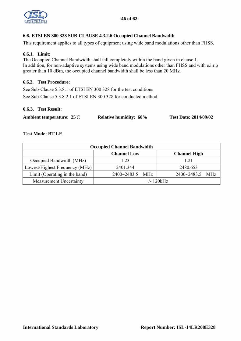
6.6. ETSI EN 300 328 SUB-CLAUSE 4.3.2.6 Occupied Channel Bandwidth
This requirement applies to all types of equipment using wide band modulations other than FHSS. 6.6.1. Limit: The Occupied Channel Bandwidth shall fall completely within the band given in clause 1. In addition, for non-adaptive systems using wide band modulations other than FHSS and with e.i.r.p greater than 10 dBm, the occupied channel bandwidth shall be less than 20 MHz. 6.6.2. Test Procedure:
See Sub-Clause 5.3.8.1 of ETSI EN 300 328 for the test conditions
See Sub-Clause 5.3.8.2.1 of ETSI EN 300 328 for conducted method.
6.6.3. Test Result:
Ambient temperature: 25℃ Relative humidity: 60% Test Date: 2014/09/02
Test Mode: BT LE
Occupied Channel Bandwidth
Channel Low Channel High
Occupied Bandwidth (MHz) 1.23 1.21
Lowest/Highest Frequency (MHz) 2401.344 2480.653
Limit (Operating in the band) 2400~2483.5 MHz 2400~2483.5 MHz
Measurement Uncertainty +/- 120kHz
-47 of 62-
International Standards Laboratory Report Number: ISL-14LR208E328
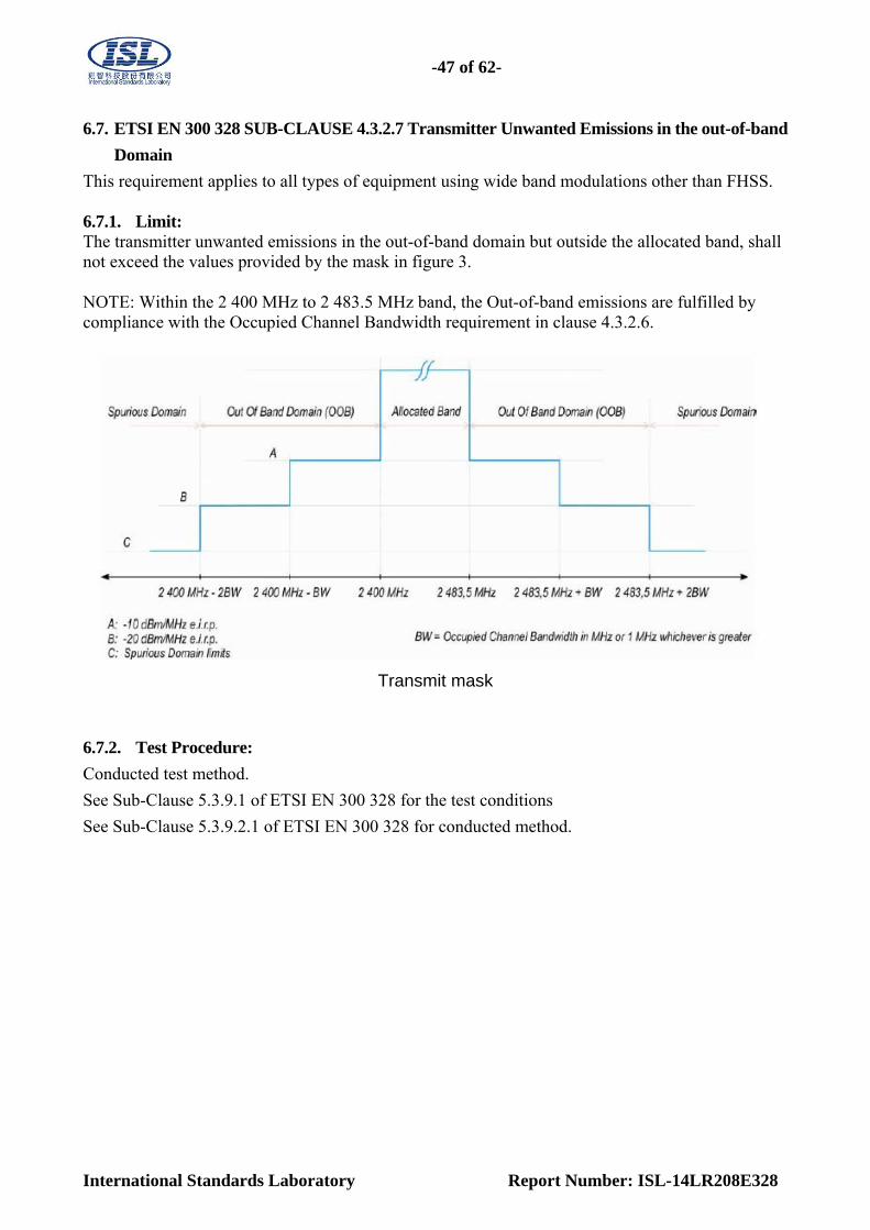
6.7. ETSI EN 300 328 SUB-CLAUSE 4.3.2.7 Transmitter Unwanted Emissions in the out-of-band
Domain
This requirement applies to all types of equipment using wide band modulations other than FHSS. 6.7.1. Limit: The transmitter unwanted emissions in the out-of-band domain but outside the allocated band, shall not exceed the values provided by the mask in figure 3. NOTE: Within the 2 400 MHz to 2 483.5 MHz band, the Out-of-band emissions are fulfilled by compliance with the Occupied Channel Bandwidth requirement in clause 4.3.2.6.
Transmit mask
6.7.2. Test Procedure:
Conducted test method.
See Sub-Clause 5.3.9.1 of ETSI EN 300 328 for the test conditions
See Sub-Clause 5.3.9.2.1 of ETSI EN 300 328 for conducted method.
-48 of 62-
International Standards Laboratory Report Number: ISL-14LR208E328
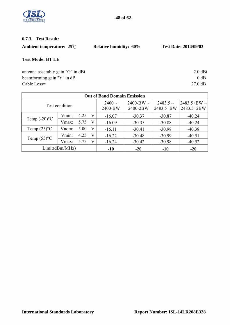
6.7.3. Test Result:
Ambient temperature: 25℃ Relative humidity: 60% Test Date: 2014/09/03
Test Mode: BT LE antenna assembly gain "G" in dBi 2.0 dBibeamforming gain "Y" in dB 0 dBCable Loss= 27.0 dB
Out of Band Domain Emission
Test condition 2400 ~
2400-BW 2400-BW ~2400-2BW
2483.5 ~ 2483.5+BW
2483.5+BW ~2483.5+2BW
Temp (-20)°C Vmin: 4.25 V -16.07 -30.37 -30.87 -40.24 Vmax: 5.75 V -16.09 -30.35 -30.88 -40.24
Temp (25)°C Vnom: 5.00 V -16.11 -30.41 -30.98 -40.38
Temp (55)°C Vmin: 4.25 V -16.22 -30.48 -30.99 -40.51 Vmax: 5.75 V -16.24 -30.42 -30.98 -40.52
Limit(dBm/MHz) -10 -20 -10 -20

-49 of 62-
International Standards Laboratory Report Number: ISL-14LR208E328
6.1. ETSI EN 300 328 SUB-CLAUSE 4.3.2.8 Transmitter Unwanted Emissions in the Spurious
Domain
This requirement applies to all types of equipment using wide band modulations other than FHSS. 6.1.1. Limit:
The transmitter unwanted emissions in the spurious domain shall not exceed the values given in table
Transmitter limits for Narrowband Spurious emissions
Frequency Range Maximum power, e.r.p. (≤ 1 GHz)
e.i.r.p. (> 1 GHz)
Measurement Bandwidth
30 MHz to 47 MHz -36 dBm 100 kHz
47 MHz to 74 MHz -54 dBm 100 kHz
74 MHz to 87,5 MHz -36 dBm 100 kHz
87,5 MHz to 118 MHz -54 dBm 100 kHz
118 MHz to 174 MHz -36 dBm 100 kHz
174 MHz to 230 MHz -54 dBm 100 kHz
230 MHz to 470 MHz -36 dBm 100 kHz
470 MHz to 862 MHz -54 dBm 100 kHz
862 MHz to 1 GHz -36 dBm 100 kHz
1 GHz to 12,75 GHz -30 dBm 1 MHz
6.1.2. Test Procedure:
See Sub-Clause 5.3.10.1 of ETSI EN 300 328 for the test conditions
See Sub-Clause 5.3.10.2.1.1 and 5.3.10.2.1.2 of ETSI EN 300 328 for Conducted Pre-Scan test
method.
See Sub-Clause 5.3.10.2.2 of ETSI EN 300 328 for final Radiated test method.

-50 of 62-
International Standards Laboratory Report Number: ISL-14LR208E328
6.1.3. Test Result: Radiated
Test Mode: LE mode, TX CH Low
Ambient temperature: 25℃ Relative humidity: 60% Test Date: 2014/09/04
No Freq Reading Aux Level Limit Over Limit
Pol
MHz dBm dB dBm dBm dB V/H 1 47.46 -67.49 6.15 -61.34 -54.00 -7.34 VERTICAL 2 106.63 -60.80 0.33 -60.47 -54.00 -6.47 VERTICAL 3 296.75 -63.58 -1.27 -64.85 -36.00 -28.85 VERTICAL 4 504.33 -69.16 3.30 -65.86 -54.00 -11.86 VERTICAL 5 576.11 -72.93 4.90 -68.03 -54.00 -14.03 VERTICAL 6 813.76 -75.77 8.87 -66.90 -54.00 -12.90 VERTICAL 7 4804.00 -52.47 11.44 -41.03 -30.00 -11.03 VERTICAL 1 47.46 -63.94 6.14 -57.80 -54.00 -3.80 HORIZONTAL2 109.54 -63.56 -2.16 -65.72 -54.00 -11.72 HORIZONTAL3 185.20 -61.68 -3.49 -65.17 -54.00 -11.17 HORIZONTAL4 223.03 -60.28 -3.72 -64.00 -54.00 -10.00 HORIZONTAL5 296.75 -65.81 -0.55 -66.36 -36.00 -30.36 HORIZONTAL6 813.76 -71.79 8.94 -62.85 -54.00 -8.85 HORIZONTAL7 4804.00 -47.21 11.85 -35.36 -30.00 -5.36 HORIZONTAL
Measurement uncertainty 30MHz - 80MHz: 5.04dB
80MHz -1000MHz: 3.76dB
1GHz - 26GHz: 4.45dB
Remark: 1. The emission behaviors belong to narrowband spurious emission.
2. Remark '' --- '' means that the emission level is too low to be measured
3. The result basic equation calculation is as follows:
4. ERP/EIRP (dBm) = SG Setting(dBm) + Antenna Gain (dB/dBi) – Cable loss (dB)
5. Measurement Range upto 12.75GHz.
-51 of 62-
International Standards Laboratory Report Number: ISL-14LR208E328
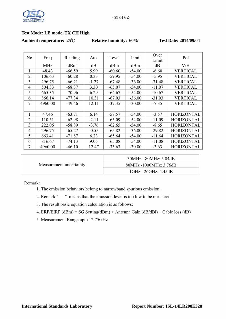
Test Mode: LE mode, TX CH High
Ambient temperature: 25℃ Relative humidity: 60% Test Date: 2014/09/04
No Freq Reading Aux Level Limit Over Limit
Pol
MHz dBm dB dBm dBm dB V/H 1 48.43 -66.59 5.99 -60.60 -54.00 -6.60 VERTICAL 2 106.63 -60.28 0.33 -59.95 -54.00 -5.95 VERTICAL 3 296.75 -66.21 -1.27 -67.48 -36.00 -31.48 VERTICAL 4 504.33 -68.37 3.30 -65.07 -54.00 -11.07 VERTICAL 5 665.35 -70.96 6.29 -64.67 -54.00 -10.67 VERTICAL 6 866.14 -77.34 10.31 -67.03 -36.00 -31.03 VERTICAL 7 4960.00 -49.46 12.11 -37.35 -30.00 -7.35 VERTICAL 1 47.46 -63.71 6.14 -57.57 -54.00 -3.57 HORIZONTAL2 110.51 -62.98 -2.11 -65.09 -54.00 -11.09 HORIZONTAL3 222.06 -58.89 -3.76 -62.65 -54.00 -8.65 HORIZONTAL4 296.75 -65.27 -0.55 -65.82 -36.00 -29.82 HORIZONTAL5 663.41 -71.87 6.23 -65.64 -54.00 -11.64 HORIZONTAL6 816.67 -74.13 9.05 -65.08 -54.00 -11.08 HORIZONTAL7 4960.00 -46.10 12.47 -33.63 -30.00 -3.63 HORIZONTAL
Measurement uncertainty 30MHz - 80MHz: 5.04dB
80MHz -1000MHz: 3.76dB
1GHz - 26GHz: 4.45dB
Remark: 1. The emission behaviors belong to narrowband spurious emission.
2. Remark '' --- '' means that the emission level is too low to be measured
3. The result basic equation calculation is as follows:
4. ERP/EIRP (dBm) = SG Setting(dBm) + Antenna Gain (dB/dBi) – Cable loss (dB)
5. Measurement Range upto 12.75GHz.

-52 of 62-
International Standards Laboratory Report Number: ISL-14LR208E328
6.2. ETSI EN 300 328 SUB-CLAUSE 4.3.2.9 Receiver Spurious Emissions
This requirement applies to all types of equipment using wide band modulations other than FHSS. 6.2.1. Limit:
The spurious emissions of the receiver shall not exceed the values given in table
Spurious emission limits for receivers
Frequency Range Maximum power, e.r.p. (≤ 1 GHz)
e.i.r.p. (> 1 GHz)
Measurement Bandwidth
30 MHz to 1 GHz -57 dBm 100 kHz
1 GHz to 12,75 GHz -47 dBm 1 MHz
6.2.2. Test Procedure:
See Sub-Clause 5.3.11.1 of ETSI EN 300 328 for the test conditions
See Sub-Clause 5.3.11.2.1 and 5.3.11.2.2 of ETSI EN 300 328 for Conducted Pre-Scan test method.
See Sub-Clause 5.3.11.2.2 of ETSI EN 300 328 for final Radiated test method.
-53 of 62-
International Standards Laboratory Report Number: ISL-14LR208E328
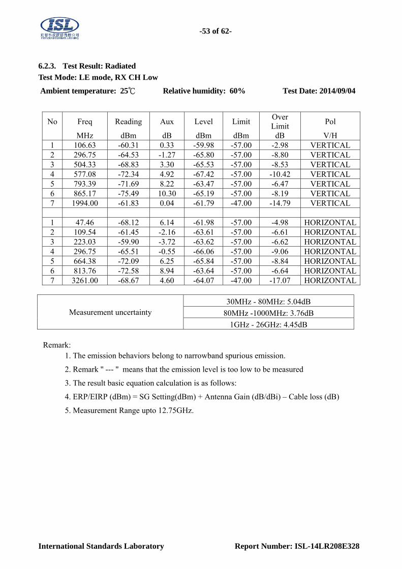
6.2.3. Test Result: Radiated
Test Mode: LE mode, RX CH Low
Ambient temperature: 25℃ Relative humidity: 60% Test Date: 2014/09/04
No Freq Reading Aux Level Limit Over Limit
Pol
MHz dBm dB dBm dBm dB V/H 1 106.63 -60.31 0.33 -59.98 -57.00 -2.98 VERTICAL 2 296.75 -64.53 -1.27 -65.80 -57.00 -8.80 VERTICAL 3 504.33 -68.83 3.30 -65.53 -57.00 -8.53 VERTICAL 4 577.08 -72.34 4.92 -67.42 -57.00 -10.42 VERTICAL 5 793.39 -71.69 8.22 -63.47 -57.00 -6.47 VERTICAL 6 865.17 -75.49 10.30 -65.19 -57.00 -8.19 VERTICAL 7 1994.00 -61.83 0.04 -61.79 -47.00 -14.79 VERTICAL 1 47.46 -68.12 6.14 -61.98 -57.00 -4.98 HORIZONTAL2 109.54 -61.45 -2.16 -63.61 -57.00 -6.61 HORIZONTAL3 223.03 -59.90 -3.72 -63.62 -57.00 -6.62 HORIZONTAL4 296.75 -65.51 -0.55 -66.06 -57.00 -9.06 HORIZONTAL5 664.38 -72.09 6.25 -65.84 -57.00 -8.84 HORIZONTAL6 813.76 -72.58 8.94 -63.64 -57.00 -6.64 HORIZONTAL7 3261.00 -68.67 4.60 -64.07 -47.00 -17.07 HORIZONTAL
Measurement uncertainty 30MHz - 80MHz: 5.04dB
80MHz -1000MHz: 3.76dB
1GHz - 26GHz: 4.45dB
Remark: 1. The emission behaviors belong to narrowband spurious emission.
2. Remark '' --- '' means that the emission level is too low to be measured
3. The result basic equation calculation is as follows:
4. ERP/EIRP (dBm) = SG Setting(dBm) + Antenna Gain (dB/dBi) – Cable loss (dB)
5. Measurement Range upto 12.75GHz.

-54 of 62-
International Standards Laboratory Report Number: ISL-14LR208E328
Test Mode: LE mode, RX CH High
Ambient temperature: 25℃ Relative humidity: 60% Test Date: 2014/09/04
No Freq Reading Aux Level Limit Over Limit
Pol
MHz dBm dB dBm dBm dB V/H 1 48.43 -67.30 5.99 -61.31 -57.00 -4.31 VERTICAL 2 106.63 -60.60 0.33 -60.27 -57.00 -3.27 VERTICAL 3 295.78 -64.96 -1.28 -66.24 -57.00 -9.24 VERTICAL 4 504.33 -69.19 3.30 -65.89 -57.00 -8.89 VERTICAL 5 792.42 -70.88 8.20 -62.68 -57.00 -5.68 VERTICAL 6 855.47 -77.15 10.23 -66.92 -57.00 -9.92 VERTICAL 7 2806.00 -67.87 2.53 -65.34 -47.00 -18.34 VERTICAL 1 47.46 -67.00 6.14 -60.86 -57.00 -3.86 HORIZONTAL2 109.54 -61.53 -2.16 -63.69 -57.00 -6.69 HORIZONTAL3 223.03 -63.13 -3.72 -66.85 -57.00 -9.85 HORIZONTAL4 295.78 -64.78 -0.59 -65.37 -57.00 -8.37 HORIZONTAL5 665.35 -71.39 6.27 -65.12 -57.00 -8.12 HORIZONTAL6 813.76 -74.24 8.94 -65.30 -57.00 -8.30 HORIZONTAL7 2323.00 -66.45 1.40 -65.05 -47.00 -18.05 HORIZONTAL
Measurement uncertainty 30MHz - 80MHz: 5.04dB
80MHz -1000MHz: 3.76dB
1GHz - 26GHz: 4.45dB
Remark: 1. The emission behaviors belong to narrowband spurious emission.
2. Remark '' --- '' means that the emission level is too low to be measured
3. The result basic equation calculation is as follows:
4. ERP/EIRP (dBm) = SG Setting(dBm) + Antenna Gain (dB/dBi) – Cable loss (dB)
5. Measurement Range upto 12.75GHz.
-55 of 62-
International Standards Laboratory Report Number: ISL-14LR208E328
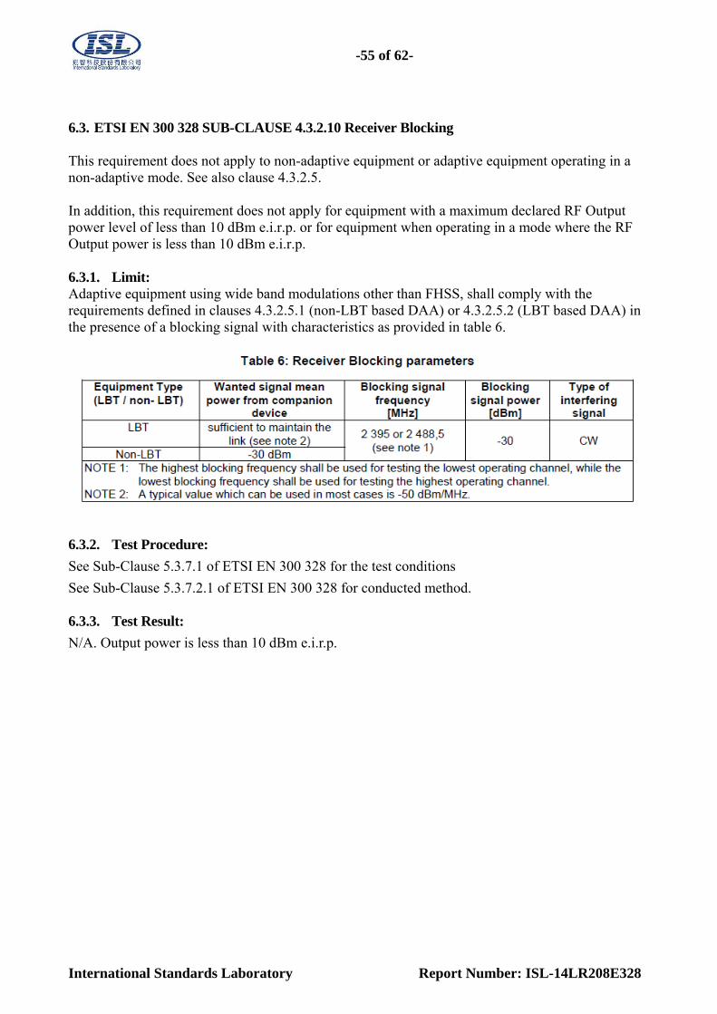
6.3. ETSI EN 300 328 SUB-CLAUSE 4.3.2.10 Receiver Blocking This requirement does not apply to non-adaptive equipment or adaptive equipment operating in a non-adaptive mode. See also clause 4.3.2.5. In addition, this requirement does not apply for equipment with a maximum declared RF Output power level of less than 10 dBm e.i.r.p. or for equipment when operating in a mode where the RF Output power is less than 10 dBm e.i.r.p. 6.3.1. Limit: Adaptive equipment using wide band modulations other than FHSS, shall comply with the requirements defined in clauses 4.3.2.5.1 (non-LBT based DAA) or 4.3.2.5.2 (LBT based DAA) in the presence of a blocking signal with characteristics as provided in table 6.
6.3.2. Test Procedure:
See Sub-Clause 5.3.7.1 of ETSI EN 300 328 for the test conditions
See Sub-Clause 5.3.7.2.1 of ETSI EN 300 328 for conducted method. 6.3.3. Test Result:
N/A. Output power is less than 10 dBm e.i.r.p.
-56 of 62-
International Standards Laboratory Report Number: ISL-14LR208E328
APPENDIX 1
PHOTOGRAPHS OF SET UP

-57 of 62-
International Standards Laboratory Report Number: ISL-14LR208E328
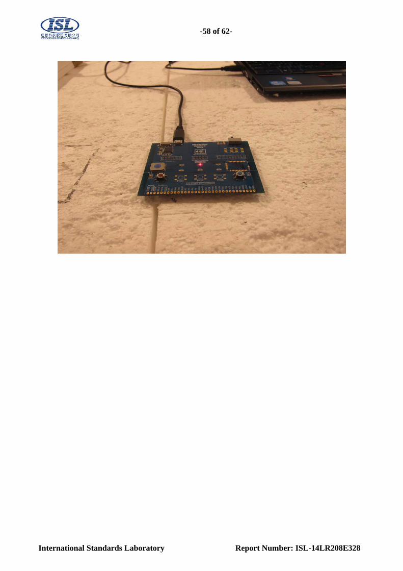
Front of Set up
Back of Set up
-58 of 62-
International Standards Laboratory Report Number: ISL-14LR208E328

-59 of 62-
International Standards Laboratory Report Number: ISL-14LR208E328
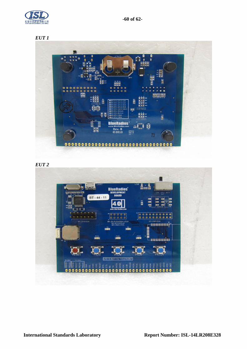
APPENDIX 2
PHOTOGRAPHS OF EUT
-60 of 62-
International Standards Laboratory Report Number: ISL-14LR208E328
EUT 1
EUT 2

-61 of 62-
International Standards Laboratory Report Number: ISL-14LR208E328
EUT 3
EUT 4
BT Antenna

-62 of 62-
International Standards Laboratory Report Number: ISL-14LR208E328
EUT 5
EUT 6
~ End of Report ~