14-i fuel system - pajero 4x4
TRANSCRIPT
14-I
FUEL SYSTEM CONTENTS
AUTO-CRUISE CONTROL SYSTEM ................................. 106 AUTO-CRUISE CONTROL ............................................ 134 SERVICE ADJUSTMENT PROCEDURES ..................... 125
Accelerator Cables Inspection and Adjustment ....... 127 Auto-cruise Control System Inspection .................... 125 Individual Parts Inspection ....................................... 128
SPEClALTOOLS ........................................................... 106 SPECIFICATIONS ......................................................... 106
General Specifications .............................................. I 06 Service Specifications ........................................... . . 106 Torque Specification ........... ___________ _.__.-__.- _._-_____ 106
TROUBLESHOOTING .............. ..“. ................................ 107 Auto-cruise Control Components Location ........... _- 123 Auto-cruise Control Related Harnesses ................... 122 Check Chart ............................................ _____._ -___- 111 Input Check ......... ..- ............................................ ____ 121 Self-diagnosis Check .............. ___._._I___ 119 Troubleshooting Quick-reference Chart ................... 107
ENGINE CONTROL ............................................................ 102 ACCELERATOR CABLE AND PEDAL ........................... 104 SERVlCE ADJUSTMENT PROCEDURES ..................... 102
Accelerator Cable Free Play Adjustment .................. 102 SPECIFICATION ........................................................... 102
Service Specification ..................... -_-_------ 102 Torque Specifications ............................................ -_ 102
TROUBLESHOOTlNG ................................................... 102 FBC SYSTEM ..................................................................... 2
CARBURETOR .............................................................. 34 FBC SYSTEM INSPECTION ......................................... 25
Components Location ................ ___-__ ...................... Electric Choke Relay ..............ll. ..... --_. ......... .._. _-_ Engine Coolant Temperature Sensor ....................... Engine Speed Sensor ............................................... Feedback Solenoid Valve .......................................... Oxygen Sensor ......................................................... Slow Cut Solenoid Valve ..................... .- .................... Throttle Opener Control Solenoid Valve for Air Conditioner ............................... ..~ ........... ___ . _._-- Throttle Position Sensor ...........................................
ii: 30 31 32 31 32
32 30
Vacuum Switch ......................................................... 31 FUEL LINE AND VAPOR LINE ...................................... 52 FUEL PUMP ................................................................... 46 FUEL TANK ................................................................... 50 SERVICE ADJUSTMENT PROCEDURES ..................... 11
Carburetor Appearance ............................................ Carburetor Inspection ............................................... Dash Pot Adjustment .................................. . . .--- - Fuel Filter Replacement ............................................ Fuel Gauge Unit and Pipe Assembly Replacement . Idle Speed Adjustment ............................................. Idle Speed and Mixture Adjustment ......................... Idle Speed Check Procedure .................................... Overfill Limiter (Two-way Valve) Replacement ......... Throttle Opener Adjustment for Air Conditioner ...... Throttle Position Sensor Adjustment .......................
SPECIALTOOLS ...........................................................
11 15 15 24 24 11 11 11 24 13 13 4
SPECIFICATIONS ................. 3.. ................................... 2 General Specifications .............................................. 2 Service Specifications .............................................. 3 Torque Specifications ........ .._ .................................... 4
TROUBLESHOOTING ................................................... 5 Circuit Diagrams ....................................................... 9 Control Functions Table ............................................ 8 Fuel Tank and Fuel tine ............................................ 7
MPISYSTEM ..................................................................... 54 FUEL LINE AND VAPOR LINE ...................................... 99 FUEL TANK ................................................................... 96 INJECTOR .............................................................. ..” ... 90 MPI SYSTEM INSPECTION .......................................... 71
Air Conditioner Switch ...................... ..- .................... 86 Air Conditioner Power Relay ..................................... 89 Components Location .............................................. 71 Control Relay ................. _.___________-___- .-......._ ............ 88 EGR Control Solenoid Valve (M/T models only) ........ 89 EGR Temperature Sensor California only) ............... 86 Engine Coolant Temperature Sensor ....................... 84 Idle Position Switch .................................................. 85 Idle Speed Control Servo (Stepper Motor) ................ 87 Inhibitor Switch ......................................................... 86 Injectors ..................... -__~ - ................................. 86 Intake Air Temperature Sensor ................................. 84 Malfunction Indicator Light ...................................... 74 Oxygen Sensor ........................... _____-____ .................. 86 Power Steering Oil Pressure Switch ......................... 86 Power Transistor ...................................................... 89 Purge Control Solenoid Valve ................................... 89 Self-diagnosis ........................................................... 75 Throttle Position Sensor ........................................... 85 Vehicle Speed Sensor ............................................... 86
SERVICE ADJUSTMENT PROCEDURES ..................... 62 Basic Idle Speed Adjustment ................................... 63 Curb Idle Speed inspection ......... .._- ....................... 62 EGR Valve Control Vacuum Check ............................ 70 Fixed SAS Adjustment .............................................. 66 Fuel Filter Replacement ............................................ 67 Fuel Gauge Unit Replacement .................................. 67 Fuel Pressure Measurement .................................... 68 Fuel Pump Connector Disconnection (Howto Reducethe Fuel Line Internal Pressure) ..... 67 Fuel Pump Operation Check ........................... ..- ...... 68 Idle Position Switch andThrottle Position Sensor Adjustment ............................................................... 65 Overfill Limiter(Two-way Valve) Replacement ......... 67 Purge Port Vacuum Check ........................................ 70 Throttle Body (Throttle Valve Area) Cleaning ....... .... 65
SPECIAL TOOLS ........................................................... 56 SPECIFICATlONS ......................................................... 54
General Specifications .............................................. 54 Service Specifications .............................................. 55 Torque Specifications ............................................... 55
THROTI-LE BODY ......................................................... 93 TROUBLESHOOTlNG ................................................... 56
Circuit Diagrams ....................................................... 60 Control Functions ................................ -_ ._ ............... 59 Fuel Tank and Fuel Line ............................................ 62
14-2 FBC SYSTEM - SDecifications
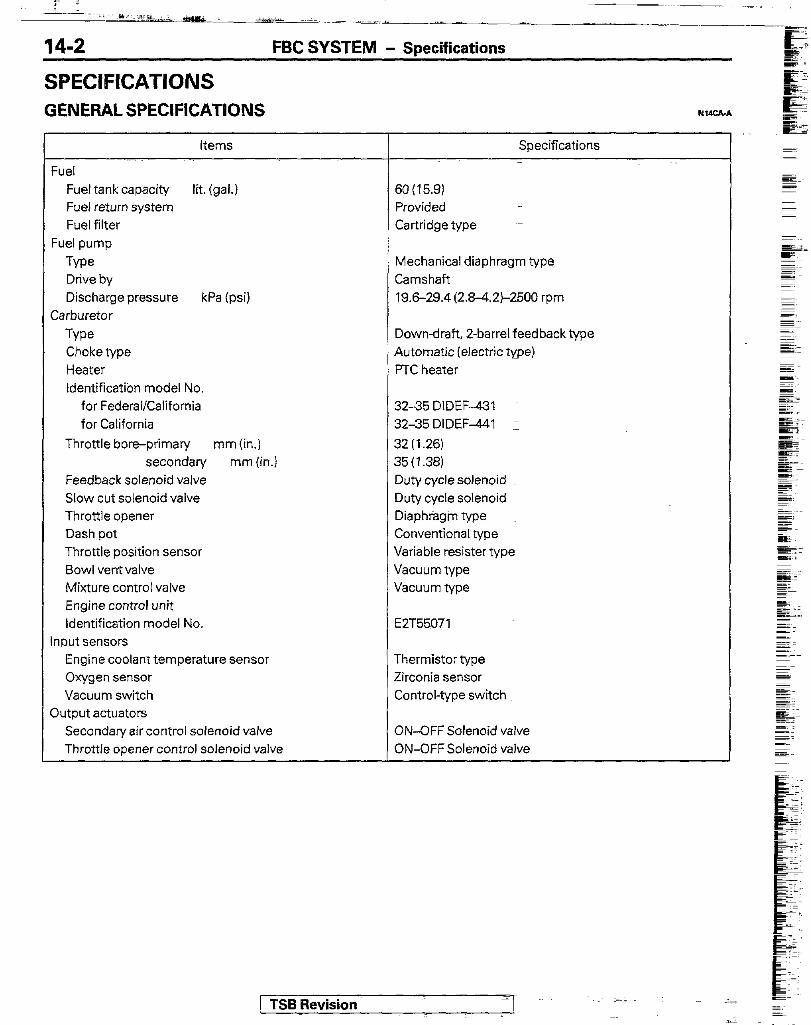
SPECIFICATIONS GENERAL SPECIFICATIONS
Items Specifications
Fuel tank capacity lit. (gal.) Fuel return system Fuel filter
Fuel pump
Type Drive by Discharge pressure kPa (psi)
Carburetor
Type Choke type Heater IdentificatTon model No.
for Federal/California for California
Throttle bore-primary mm (in.) secondary mm (in.)
Feedback solenoid valve Slow cut solenoid valve Throttle opener Dash pot Throttle position sensor Bowl ventvalve Mixture control valve Engine control unit Identification model No.
Input sensors Engine coolant temperature sensor Oxygen sensor Vacuum switch
Output actuators Secondary air control solenoid valve Throttle opener control solenoid valve
SO(15.9) Provided Cartridge type
Mechanical diaphragm type Camshaft 19.6-29.4 (2.8-4.2~2500 rpm
Downdraft, Z-barrel feedback type Automatic (electric type) PTC heater
3235 DlDEF-431 32-35 DIDEF-1 I
32(1.26) 35 (1.38) Duty cycle solenoid Duty cycle solenoid Diaphragm type Conventional type Variable resister type Vacuum type Vacuum type
EZT55971
Thermistor type Zirconia sensor Control-type switch
ON-OFF Solenoid valve ON-OFF Solenoid valve
/ TSB Revision

FBC SYSTEM - Specifications 14-3
SERWCE SPECIFICATIONS
Items Specifications
Standard value Engine adjustments
Basic ignition timing 7”+ 2”BTDC at curb idle
Actual ignition timing at high altitude-Federal/California and Approx. 12”BTDC high altitude vehicles for Federal Curb idle speed wm
For the first 500 km (300 miles) 725:;;; After 500 km (300 miles) 800-c 100
Throttle opener adjustment Rpm for air conditioner load rpm 900-950 (when air conditioner ON)
Dash pot touch rpm wm 2000 Throttle-position sensor Adjustment voltage (throttle valve completely closed) V 0.250
Carburetor Main jet - primary # 107.5
secondary #I90 Pilot jet- primary #55
secondary #70 Enrichment jet #65 Automatic choke heater Continuity-approx. 6 D [at 20°C (68”F)] Choke breaker opening mm (in.)
1 st stage 2.3-2.5 (.091-0.98)
2nd stage 3.0-3.2(.118-,126) First idle rpm Approx. 2,350
Feedback solenoid valve coil resistance n 54-66 [at 20°C (68”F)] Slow cut-off solenoid valve coil resistance D 48-60 [at 20°C (68”F)]
Throttle-position sensor resistance kn 3.5-6.5
Input sensor Engine coolant temperature sensor resistance kD
20°C (68°F) 2.5
80°C ( 176°F) 0.3
Oxygen sensor output voltage V Approx. 1
Vacuum switch ON more than 40 kPa (5.8 psi) OFF less than 26 kPa (3.9 psi)
Output actuator Secondary air solenoid valve resistance n 36-44 [at 20°C (68”F)]
Throttle opener control solenoid valve resistance n 40-48 [at 20°C (68’F)]
/ TSB Revision
14-4 FBC SYSTEM - Specifications / Special Tools
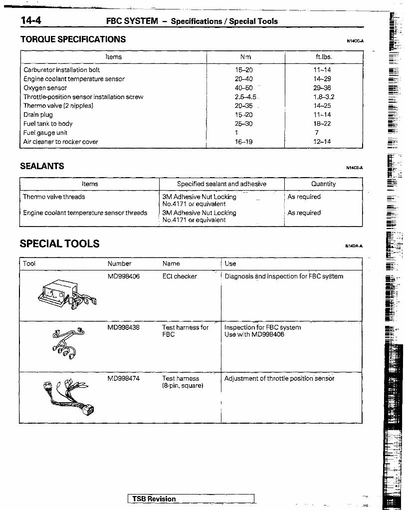
TORQUE SPEClFlCATlONS
Items
Carburetor installation bolt Engine coolant temperature sensor Oxygen sensor Throttle-position sensor installation screw Therm0 valve (2 nipples) Drain plug Fuel tank to body Fuel gauge unit Air cleaner to rocker cover
i
SEALANTS
5 Nm
15-20 - 20-40 4060 2.wa.5 20-35 15-20 2530 I 16-19
ftlbs. -. -
11-14 14-29 29-36 1.8-3.2 14-25 11-14 18-22 7 12-14
NWCC-A
NucE.A
items I Specified sealant and adhesive I Quantity I
Therm0 valve threads 3M Adhesive Nut Locking’ No.4171 or equivalent
Engine coolant temperature sensor threads 3M Adhesive Nut Locking No.4171 or equivalent
As required
As required
SPECIAL TOOLS
roo1 Number
( TSB Revision
FBC SYSTEM - Troubleshooting
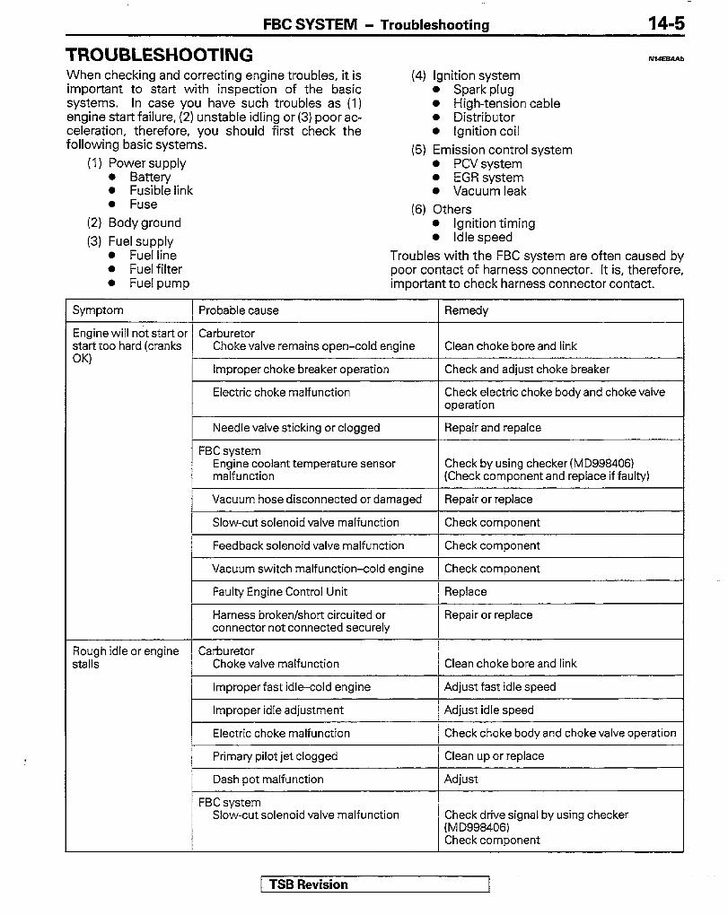
TROUBLESHOOTING When checking and correcting engine troubles, it is (4) Ignition system important to start with inspection of the basic 0 Spark plug systems. In case you have such troubles as (1) l High-tension cable engine start failure, (2) unstable idling or (3) poor ac- l Distributor celeration, therefore, you should first check the l Ignition coil following basic systems. (5) Emission control system
14-5
NI4.5BA.a
l Fusible link l Fuse
(2) Body ground
(3) Fuel supply l Fuel line l Fuel filter
l PCVsystem l EGR system l Vacuum leak
(6) Others l Ignition timing l Idle speed
Troubles with the FBC system are often caused by poor contact of harness connector. It is, therefore,
l Fuel pump important to check harness connector contact.
Symptom
Engine will not start 01 start too hard (cranks W
3ough idle or engine jtallS
Probable cause
Carburetor
Remedy
Choke valve remains open-cold engine Clean choke bore and link
Check and adjust choke breaker
Electric choke malfunction Check electricchoke bodyand chokevalve operation
Needle valve sticking or clogged Repair and repalce
FBC system Engine coolant temperature sensor malfunction
Check by using checker (MD9984061 (Check component and replace if faulty)
Vacuum hose disconnected or damaged 1 Repair or replace
Slow-cut solenoid valve malfunction Check component
Feedback solenoid valve malfunction Check component
Vacuum switch malfunction-cold engine Check component
Faulty Engine Control Unit
Harness broken/short circuited or connector not connected securely
Replace
Repair or replace
Carburetor Choke valve malfunction Clean choke bore and link
Improperfast idle-cold engine
Improper idle adjustment
Electric choke malfunction
Primary pilot jet clogged
Dash pot malfunction
FBC system Slow-cut solenoid valve malfunction
Adjust fast idle speed
~ Adjust idle speed
Check choke body and choke valve operation
Clean up or replace
Adjust
Check drive signal by using checker (MD998406) Check component
1 TSB Revision
I . .
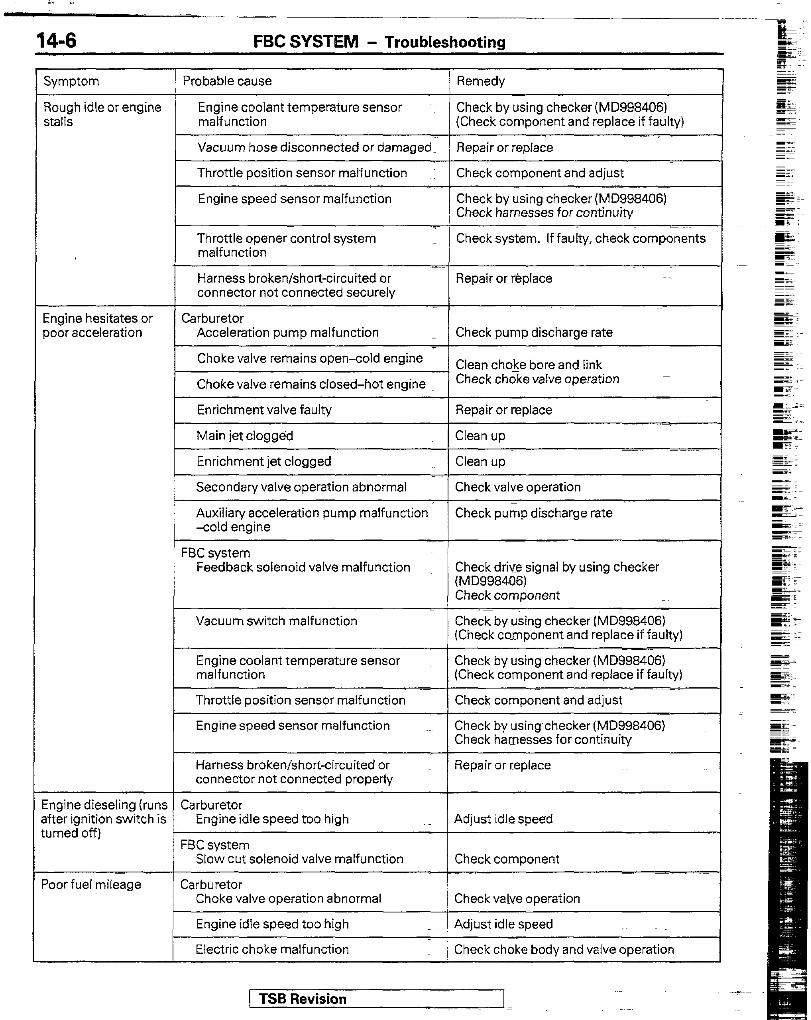
14-6 FBC SYSTEM - Troubleshooting
Symptom 1 Probable cause Remedy
Rough idle or engine Engine coolant temperature sensor -~ Check by using checker (MD998406) stalls malfunction (Check component and replace if faulty)
Vacuum hose disconnected or damaged. Repair or replace
Throttle position sensor malfunction Check component and adjust --
Engine speed sensor malfunction Check by using checker (MD998406) Check harnesses for continuity
Throttle opener control system malfunction
Check system. If faulty, check components
tngine hesitates or 3001 acceleration
Harness broken/short-circuited or Repair or replace connector not connected securely
-~ Carburetor
Acceleration pump malfunction _ Check pump discharge rate
Choke valve remains open-cold engine 1~ Clean choke bore and link-
Check chgke valve operation - Choke valve remains closed-hot engine
Enrichment valve faulty Repair or replace
Main jet clogged Clean up
Enrichment jet clogged Clean up
Secondary valve operation abnormal Check valve operation
Auxiliary acceleration pump malfunction Check pump discharge rate -cold engine
FBC system Feedback solenoid valve malfunction Check drive signal by using checker
(MD998406) Check component
Vacuum switch malfunction Check by using checker (MD998406) (Check component and replace if faulty)
Engine coolant temperature sensor Check by using checker (MD998406) malfunction (Check component and replace if faulty)
- Throttle position sensor malfunction
Engine speed sensor malfunction
Check component and adjust
Check by using checker (MD9984061 Check harnesses for continuity
Harness broken/short-circuited or Repair or replace connector not connected properly
.~ ~~~ ingine dieseIrng (runs Carburetor ifter ignition switch is Engine idle speed too high _ Adjust idle speed urned off)
FBC system Slow cut solenoid valve malfunction Check component
‘oar fuel mileage Carburetor Choke valve operation abnormal Check valve operation
Engine idle speed too high . Adjust idle speed
Electric choke malfunction Check choke body and valve operation

FBC SYSTEM - Troubleshootina
Symptom
Poor fuel mileage
Probable cause Remedy
Enrichment valve kept open
Auxiliary acceleration pump is in operation-hot engine
FBC system Engine coolant temperature sensor malfunction
Oxygen sensor malfunction
Feedback solenoid valve malfunction
Slow-cut solenoid valve malfunction
Throttle position sensor malfunction
Engine speed sensor malfunction
Harness broken/short circuited or connector not connected properly
FUEL TANK AND FUEL LINE
Repair or replace
Repair or replace
Check by using checker (MD998406) (Check component and replace if faulty)
Check by using checker (MD998406) (Check component and replace if faulty)
Check drivesignal by using checker (MD998406) Check component
Check drive signal by using checker (MD998406) Check components
Check component and adjust
Check by using checker (MD998406) check harnesses for continuity
Repair or replace
Symptom Probable cause 1 Remedy
Engine malfunctions due to insufficient fuel supply
Bent or kinked fuel pipe or hose Repair or replace
Clogged fuel pipe or hose Clean or replace
Clogged fuel filter or in-tank fuel filter Replace
Water in fuel filter
Dirty or rusted fuel tank interior
Malfunctioning fuel pump (Clogged filter in the pump)
Replace the fuel filter or clean the fuel tank and fuel line
Clean or replace
Replace
Evaporative emission control system malfunctions (When tank cap is removed, pressure releasing noise is heard)
Mispiping of vapor line Correct
Correct
Folded, bent, cracked or clogged vapor line
Faulty fuel tank cap
Replace
Replace
Malfunctioning overfill limiter (two-way valve)
Replace
) TSR Revision
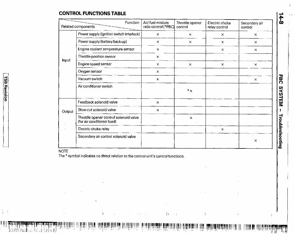
CONTROL FUNCTIONS TABLE
Function Air/fuel mixture Throttle opener Electric choke ratio control (*FBC) control
Secondary air relay control control
7
input
output
I
1 OTE
Power supply (ignition switch interlock) X X X X
Power supply (battery back-up) X X X X
Engine coolant temperature sensor X X X
Throttle-position sensor X
Engine-speed sensor X X X X
Oxygen sensor X
Vacuum switch X X
Air conditioner switch
I ‘X
I
Feedback solenoid valve X
Slow-cut solenoid valve X
Throttle opener control solenoid valve X
(for air conditioner load)
Electric choke relay
Secondary air control solenoid valve
I X
X
The * symbol indicates no direct relation to the control unit’s control functions.
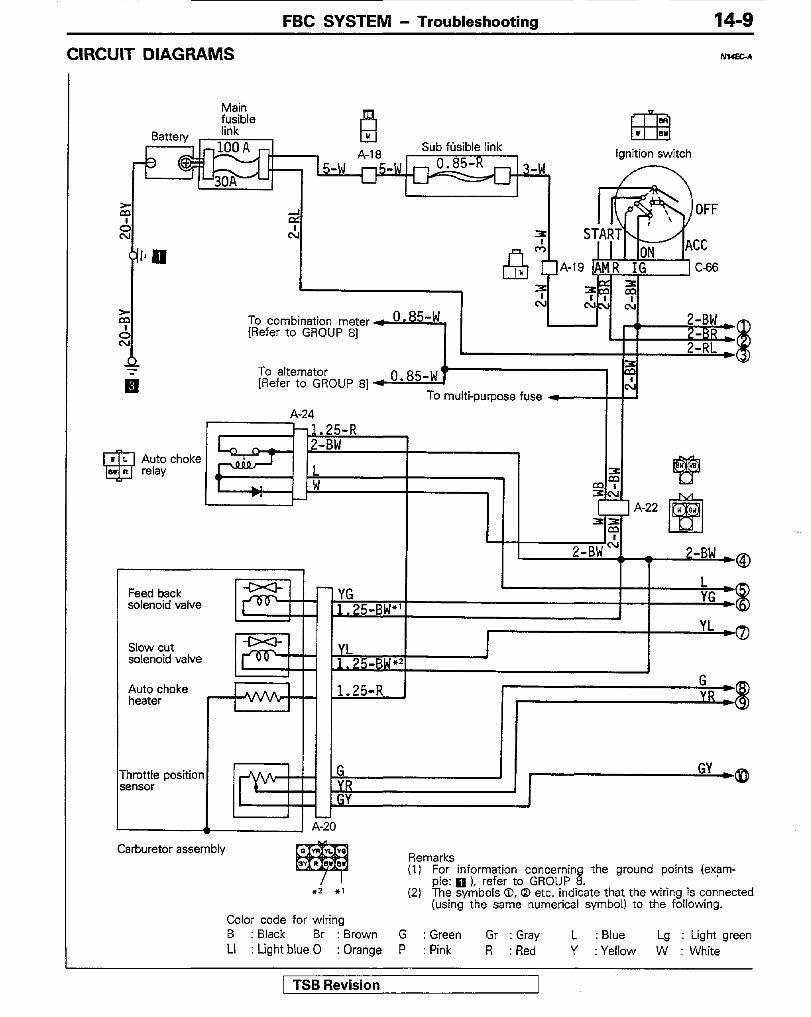
CIRCUIT DIAGRAMS
FBC SYSTEM - Troubleshooting 14-9
NI4ElL4
Main
Sub fusible link ignition switch
To alternator 13:
[Refer to GROUP 81 4 o*85-w I c\ To multi-purpose fuse w I
A-24 --1.25-R
2-BW
A-22
I I I I I
2-BW’ 1 1
7-BW ,*
Feed back solenoid valve
Slow cut solenoid valve
1 - YG
1 . J.25-BW” \G :g
YL -0 1,Y L _ s-2 1
I - c. Auto choke heater
1.25-R j b
yR 3
nrottle position msor
G . YR CD
- GY
A-20
Carburetor assembly Remarks (1) For information concernin
ple: q ). refer to GROUP 8 the ground points (exam-
. l Z l 1 (2) The symbols 0, @ etc. indicate that the wiring is connected
(using the same numerical symbol) to the following. Color code for wiring B : Black Br : Brown G : Green Gr : Gray L : Blue Lg : Light green LI : Light blue 0 : Orange P : Pink R :Red Y : Yellow W : White
/ TSB Revision

FBC SYSTEM - Troubleshooting
To vacuum solenoid valve [Refer to GROUP 81
;2-BW
q A-35. c
J 2-BW
-
---I
i 1 I
Feed back carburetor control unit
Vacuum switch
control solenoid
A-45
GY sensor
’ I 1 L- -7 B
Remarks L -----I
(1) For information concerning the ground points (exam- le: q ), refer to GROUP 8.
(2) %-re symbols @, D etc. indicate that the wiring is connected a7wlm4
(using the same numerical symbol) to the previous page. Color code for wiring B : Black Br : Brown G : Green Gr : Gray L :aue Lg : Light green LI : Light blue 0 : Orange P : Pink R : Red Y : Yellow W : White
[ TSR Revision
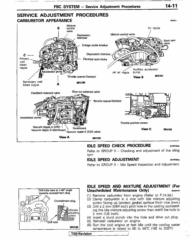
FBC SYSTEM - Service Adjustment Procedures 14-11
SERVICE ADJUSTMENT PROCEDURES CARBURETOR APPEARANCE r4I.F.L
Mixture B control Air nipple
vent
2-stage choke breaker
Depression chamber
Electrical auto-choke
Throttle openerDashpot View B 5Fu121
Sec&daty well I bleed nipple A %Ul20
I Feedback solenoid valve -Ad -
Accelerator pump-=
Vacuum nip Vacuum nipp
cuum nipple E (EGI
I valve
Throttle openerDashpot
Throttle position sensor
WSWC
View A
IDLE SPEED CHECK PROCEDURE rdmi/aa Refer to GROUP 0 - Checking and adjustment of the iding wm IDLE SPEED ADJUSTMENT NI4FHsba Refer to GROUP 0 - Idle Speed inspection and Adjustment.
Drill hole here at a 45” angle towards concealment plug
(4) Insert a blunt punch into the hole and drive out plug. (5) Reinstall carburetor on engine. (6) Run the cold engine at fast idle until the cooling water
temperature is raised to 85 to 95°C (185 to 205°F) / TSB Revision
IDLE SPEED AND MIXTURE ADJUSTMENT (For Unscheduled Maintenance Only) NIc=mF (I) Remove carburetor from engine (Refer to P.1434.) (2) Clamp carburetor in a vice with idle mixture adjusting
screw facing up (protect gasket surface from vice jaws.1 (3) Drill a 2 mm (5/64 inch) pilot hole in the casting surround-
ing the idle mixture adjusting screw then redrill the hole to 3 mm (116 inch).

14-12 FBC SYSTEM - Service Adjustment Procedures
5FU124
inspection Conditions l Engine coolant temperature: 85 - 95°C (185 - 295°F) 8 Light and accessory operation : off e Transmission : neutral l Steering wheel : center position (power steering equipped
vehicles) (7) Prepare a timing light and tachometer. (8) Depress accelerator pedal once to release the fast idle. (9) Check the cycle of the timing light. Adjust if necessary.
Timing fight cycle : PBTDC + 2”
NOTE Refer to GROUP 8 - Ignition System, for the timing cycle inspection and adjustment procedures.
(10)Turn off the ignition key. (11)Disconnect the cable from the negative terminal of the
battery for about 5 seconds. And then reconnect the cable to the original terminal.
(12)Disconnect the connector of the exhaust oxygen sensor. (13)Run the engine for more than 5 seconds at the engine
speed of 2,000 to 3,000 rpm. (14)Run ghe engine at idle for 2 minutes. (15)Set the CO-HC tester.
(16)Set the idle CO and the engine speed to the specified value by adjusting the idle speed adjusting screw No. 1 and the idle mixture adjusting screw.
ldleC0 : 0.1 to 0.3% at nominal curb idle speed Curb idle speed :
Cl725 + 158 - 100 rpm
/ *z800 f 180 rpm
NOTE 1. *I: For the first 500 -km (300 miles) 2. *2: After 500 km (300 miles) 3. If the idle CO adjustment fails, suction of secondary air
is likely. Plug the secondary air hose and try again. Caution DO NOT TOUCH the idle speed adjusting screw No. 2. The idle speed adjusting screw No. 2 is the preset screw that determines the relationship between the throttle valve and free lever, and has been accurately set at the factory. If this setting is disturbed, throttle opener adjustment and dash pot adjustment cannot be done accurately.
/ TSB Revision

FBC SYSTEM - Service Adjustment Procedures 14-13
(17)Turn off the ignition switch. (18)Connect the oxygen sensor connector. (19)lnstall the concealment plug into the hole to seal the idle
mixture adjusting screw.
THROlTLE OPENER ADJUSTMENT FOR AIR CON- DITIONER N14FKBC The throttle opener (idle-up actuator) described here controls the idle speed when the air conditioning is applied.
NOTE Check the ignition timing and idle speed before performing this adjsutment.
Inspection Conditions Engine coolant temperature : 85 - 95°C (185 - 205°F) Lights and accessories : Set to OFF Transmission : Neutral Steering wheel : Straightforward (vehicles with a power-
steering) (1) Start the engine. (2) Set the tachometer. (3) Turn on the air conditioner switch.
NOTE The solenoid valve will open and the intake manifold vacuum will act on the throttle opener to fully actuate it.
(4) Check the engine speed during this operation.
Standard value : 900-950 rpm
If the engine speed is out of specification, adjust using the throttle opener (for air conditioner) adjusting screw.
THROTTLE POSITION SENSOR ADJUSTMENzwm(; (I) Loosen the accelerator cable enough.
1 TSB Revision
. + .-
14-14 FBC SYSTEM - Service Adjustment Procedures
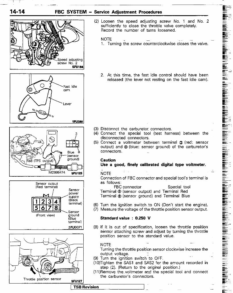
Fast idle cam
Lever
h 1D998474 5FUl25
Sensor outcut (Red tenni$alj
Sensor power suPPlY (Black terminal)
Sensor (Front view) ground
(Blue terminal)
5FUOO71
I I
(2) Loosen the speed adjusting screw No. 1 and No. 2 sufficiently to close the throttle valve completely. Record the number of turns loosened.
NOTE 1. Turning the screw counterclockwise closes the valve.
2. At this time, the fast idle control should have been released (the lever not resting on the fast idle cam).
(3) Disconnct the carburetor connectors. (4) Connect the special tool (test harness) between the
disconnected connectors. (5) Connect a voltmeter between terminal Q (red: sensor
output) and @ (blue: sensor ground) of the carburetor’s connectors.
Caution Use a good, finely calibrated digital type voltmeter.
~;~OTE Connection of FBC connector and special tool’s terminal is as follows:
FBC connector Special tool Terminal 0 (sensor output) and Terminal Red Terminal @ (sensor ground) and Terminal Blue
(6) Turn the ignition switch to ON (Don’t start the engine). (7) Measure the voltage of the throttle position sensor output.
Standard value : 0.250 V
(8) If it is out of specification, loosen the throttle position sensor attaching screw and adjust by turning the throttle position sensor to the standard value.
NOTE Turning the throttle position sensor clockwise increase the output voltage.
(9) Turn the ignition switch-to OFF. (lO)Tighten the SASI and SAM for the amount recorded in
step (2). (Return to the original position.) (11)Remove the voltmeter and the special tool and connect
the carburetor’s connectors. Throttle position sensor
5Fu127
1 TSB Revision -
I -!3! Free lever
FBC SYSTEM - Service Adjustment Procedures 14-15
(12)Adjust play of the accelerator cable. (See P.14102). (13)Start the engine and check that the idle speed is as
specified.
Standard value : Curb idle speed
For the first 500 km (300 miles) : 725 ‘:$rprn
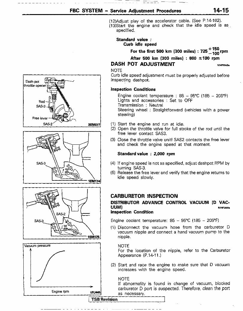
After 500 km (300 miles) : 800 nlO0 rpm DASH POT ADJUSTMENT NW=MAB. NOTE Curb idle speed adjustment must be properly adjusted before inspecting dashpot.
inspection Conditions
Engine coolant temperature : 85 - 95°C (185 - 205°F) Lights and accessories : Set to OFF Transmission : Neutral Steering wheel : Straightforward (vehicles with a power steering)
(1) Start the engine and run at idle. (2) Open the throttle valve for full stroke of the rod until the
free lever contact SAS3. (3) Close the throttle valve unit1 SAS2 contacts the free lever
and check the engine speed at that moment.
Standard value : 2,000 rpm
(4) If engine speed is not as specified, adjust dashpot RPM by turning SAS3.
(5) Release the free lever and verify that the engine returns to idle speed slowly.
CARBURETOR INSPECTION DISTRIBUTOR ADVANCE CONTROL VACUUM [D VAC- UUM) NwFwAa Inspection Condition
Engine coolant temperature: 85 - 95°C (185 - 205OF)
(1) Disconnect the vacuum hose from the carburetor D vacuum nipple and connect a hand vacuum pump to the nipple.
1 NOTE For the location of the nipple, refer to the Carburetor Appearance (P.1411.)
(2) Start and race the engine to make sure that D vacuum increases with the engine speed.
NOTE If abnormality is found in change of vacuum, blocked carburetor D port is suspected. Therefore, clean the port as necessary.
PTSB Revision

14-16 FBC SYSTEM - Service Adjustment Procedures
acuum pressure
‘1
Engine rpm lFW46
vacuum pressure
1
Engine rpm lFuu7
Vacuum pressure
Engine t-pm lFu44a
If abnormality is found in change of the vacuum, blocked car- buretor F port and vacuum passage. Therefore, disassemble
_ and check the carburetor. _ 1 TSB Revkjx ~A+ ~-
EGR VALVE CONTROL VACUUM (E VACUUM) N14FwPJI Inspection Condition o Engine coolant temperature : 85 - 95°C (185 - 205°F) (1) Disconnect the vacuum hose from the carburetor E
vacuum nipple and connect a hand vacuum pump to the nipple.
NOTE For the location of the nipple, refer to Carburetor Appear- ance (P.14-11).
(2) Start and race the engine to make sure that E vacuum increases with the engine speed.
NOTE If abnormality is found in change of vacuum, blocked carburetor E port is suspected. Therefore, clean the port as necessary.
Ml- VRV CONTROL VACUUM (A VACUUM) Inspection Condition Engine coolant temperature : 85-95°C (185- 205°F) (I) Disconnect the vacuum hose from the carburetor A vacuum
nipple and connect a hand vacuum pump to the nipple.
NOTE For the location of the nipple, refer to Carburetor Appear- ance (P.14-11).
(2) Start and race the engine to make sure that A vacuum in- creases gradually with the engine speed.
NOTE If abnormality is found in change of vacuum, blocked carbure- tor A port is suspected. Therefore, clean the port as neces- sary.
VACUUM SWITCH CONTROL VACUUM (F VACUUM)
Inspection Condition NlWMl
Engine coolant temperature : 85-95°C (185- 205°F) (1) Disconnect the vacuum hose from the carburetor vacuum nip
ple and connect a hand vacuum pump to the nipple.
NOTE For the location of the nipple, refer to Carburetor Appear- ance (P.14-11).
(2) Start and race the engine to make sure that F vacuum drops rapidly.
NOTE
-

FBC SYSTEM - Service Adiustment Procedures 14-17
ryL- -c:
I
Air inlet of additional
h-
‘I bleed air. :
Additional bleed air passage
rimarj nain jm
Prima; wel bleed nipplt
Secondary throttle valve
Primary throttle valve 1Fu3n
CARBURETOR BLEED AIR PASSAGE (CARBURETOR HIGH ALTITUDE COMPENSATION SYSTEM) N14FRAB.
PRIMARY WELL BLEED NIPPLE Federal/California and High-altitude vehicles for Federal
NOTE For the nipple position, refer to Carburetor Appearance (P.1411). (1) Disconnect the vacuum hoses from the air nipple and connect
a hand vacuum pump to the nipple. (2) Apply vacuum to see that it leaks and does not build up inside
the carburetor. (3) Disconnect the vacuum hose from the primary well bleed nip
ple and connect a hand vacuum pump. (4) Apply vacuum to see that it leaks and does not build UP
inside the carburetor. (5) If vacuum builds up, disassemble and check the carbure-
tor. (Refer to P.14-35.)
SECONDARY WELL BLEED NIPPLE High-altitude vehicles for-Federal N14msaa
I
_ Revision
NOTE For the nipple position, refer to Carburetor Appearance (P.1411.) (1) Disconnect the vacuum hose from the bleed nipple and
connect a hand vacuum pump to the nipple. (2) Apply vacuum to see that it leaks and does not build up
inside carburetor. (3) If vacuum builds up, disassemble and check the carbure-
tor. (Refer to P.14-35.) JET AIR NIPPLE High-altitude vehicles for Federal NWFRCA.
NOTE For the nipple position, refer to Carburetor Appearance (P.14 11.)
(1) Disconnect the vacuum hoses from both air nipple and jet air nipple and connect a hand vacuum pump to the nipples.
(2) Apply vacuum to see that it leaks and does not build up inside carburetor.
(3) If vacuum builds up, disassemble and check the carbure tor. (Refer to P.1435.)

FBC SYSTEM - Service Adjustment Procedures
CARBURETOR SECONDARY VALVE OPERATION N14FOAAa
(1) Remove the air cleaner assembly.
I OlR6676
Non return valve Pump nozzle , 1
Choke valve
(2) Disconnect the secondary valve vacuum hose from the car- buretor throttle body and connect a hand vacuum pump to the disconnected end of hose.
(3) With a vacuum of 13.3 kPa (1.9 psi) applied by the vacuum pump, fully open the primary throttle valve and check that the secondarythrottlevalve also opens fully.
Vacuum is not held in depression Replace depression chamber chamber (vacuum leaks)
Vacuum is held but secondary valve does not operate
Clean secondary throttle valve and related parts
CARBURETOR ACCELERATION PUMP NMFPUv
(1) Remove the air cleaner assembly cover. (2) While opening the choke valve, open the throttle valve and
check that fuel is injected from the pump nozzle. If fuel is not injected, clean the carburetor fuel passage.
CHOKE VALVE Refer to GROUP 0 - Maintenance Service.
N74FoAAb
-

FBC SYSTEM - Service Adjustment Procedures 14-19
ELECTRIC CHOKE NMFOBC
:e Two staae choke breaker
Electric auto-chol
f-----T,
Caution All carburetors have a tamper-proof choke. The choke- related parts are factory adjusted. The choke adjustment is not required during service, except when major carburetor overhaul or choke carburetor related parts adjustments are needed by state or local inspections.
(1) Check that the alignment marks on the electric choke and bimetal assembly are lined up. If not, align the marks.
NOTE 1. For removal of the bimetal assembly, refer to DISAS-
SEMBLY AND REASSEMBLY (P.14-35). -for the Feder- al/California.
2. Misalignment and resultant symptom.
-~I Poorer startability and more likely
(2) Check that engine coolant temperature is below 10°C (50°F). (3) Start the engine and check operation of the choke valve and
fast idle cam, with hand on the electric choke body.
Electric choke body
Choke valve
Fast idle cam
Gets gradually hotter after engine Start
Opens as bimetal temperature IiSeS
Fast idle control is released as en- gine coolant temperature rises and fast idle breaker operates
(4) If the electric choke body remains cool even after the engine is started, check the electric choke.
[ TSB Revision
FBC SYSTEM - Service Adiustment Procedures
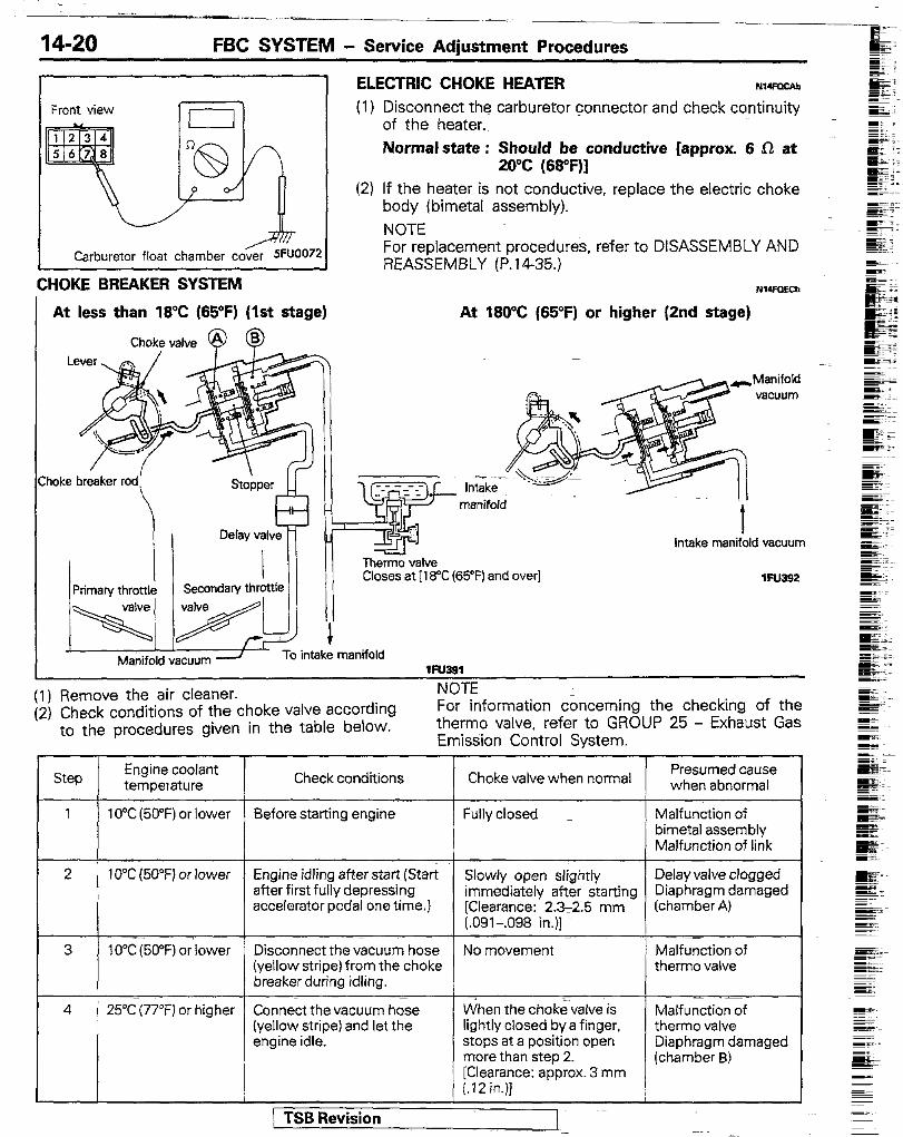
ELECTRIC CHOKE HEATER N14FOCAb (1) Disconnect the carburetor connector and check continuity
of the heater. Normal state : Should be conductive [approx. 6 R at
20°C (68aF)] (2) If the heater is not conductive, replace the electric choke
body (bimetal assembly). NOTE For replacement procedures, refer to DISASSEMBLY AND REASSEMBLY (P.14-35.)
Nl4FoEaJ
At 180°C (65°F) or higher (2nd stage)
Front view
u -:1 Carburetor float chamber cover 5Fuoo72
CHOKE BREAKER SYSTEM
At less than 18°C (65OF) (1st stage)
Choke valve @
-Manifold vacuum
__- -- _- :I .l
7 ThZ valve Closes at [l t %C (65°F) and over]
intake manifold vacuum
lFlJae2
Manifold vacuum -J To intake manifold 1FlJ391
hlnl-r (1) Remove the air cleaner. (2) Check conditions of the choke valve according
to the procedures given in the table below.
,““,L For information concerning the checking of the thermo valve, refer to GROUP 25 - Exhaust Gas Emission Control System.
Presumed cause when abnormal Check conditions Choke valve when normal
Before starting engine Malfunction of bimetal assembly Malfunction of link
2 10°C (50°F) or lower Engine idling after start (Start after first fully depressing accelerator pedal one time.)
Slowly open slightly immediately after starting [Clearance: 2.3-2.5 mm (.091-,098 in.)]
Delay valve clogged Diaphragm damaged (chamber A)
Disconnect the vacuum hose (yellow stripe) from the choke breaker during idling.
No movement Malfunction of therm0 valve
4 25°C (77°F) or higher Connect the vacuum hose (yellow stripe) and let the engine idle.
When the chok;valve is lightly closed by a finger, stops at a position open more than step 2.
Malfunction of therm0 valve Diaphragm damaged (chamber B)
[Clearance: approx. 3 mm (.I2 in.)]
- ------I - / TSB Revision

FBC SYSTEM - Service Adjustment Procedures 14-21
\
\ .
Choke bkaker rod ?- 3Fu133
CHOKE BREAKER OPENING NISOlWl
(1) After inspection of the choke breaker system, disconnect the vacuum hose (yellow stripe) from the choke breaker and make the following check.
(2) With the engine idling, close the choke valve lightly with a finger until the choke valve stops. Then, measure the choke valve to choke bore clearance.
Standard value : 2.3-2.5 mm (.091-.098 in.)
(3) If the clearance is not as specified, stop the engine, remove the bimetal assembly and adjust the rod end opening for stan- dard clearance.
NOTE For removal of the bimetal assembly, refer to DISASSEM- BLY AND REASSEMBLY (P.14-35).
-
When removing the bimetal assembly, put a mark on the elec- tric choke body.
NOTE
(4) Reconnect the removed yellow stripe vacuum hose and mea- sure the choke valve to choke bore clearance as in step (2).
Standard value : 3.0-3.2 mm (.ll&.I26 in.)
(5) If the clearance is out of specification, adjust by the adjusting screw.
NOTE
Adjusting screw turn- Valve clearance Expected result ing direction Clockwise Small Better startability but
plug more likely to get sooty
Counter clockwise Large Poor startability and stall more likely
[ TSB Revision
14-22 FBC SYSTEM - Service Adjustment Procedures
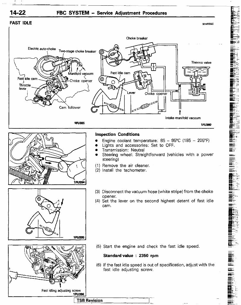
FAST IDLE NMFOGC
Choke breaker
v- Cam ‘follower
Intake manifold vacuum
1FlJ3sn
inspection Conditions o Engine coolant temperature: 85 - 95°C (185 - 205°F) l Lights and accessories: Set to OFF. l Transmission: Neutral o Steering wheel: Straightforward (vehicles with a power
steering) (1) Remove the air cleaner. (2) Install the tachometer.
lW3S§
(3) Disconnect the vacuum hose (white stripe) from the choke opener.
(4) Set the lever on the second highest detent of fast idle cam.
(5) Start the engine and check the fast idle speed.
Standardvalue : 2350 rpm
(6) If the fast idle speed is out of specification, adjust with the fast idle adjusting screw.
Fast idling adjusting screw
FBC SYSTEM - Service Adjustment Procedures 14-23
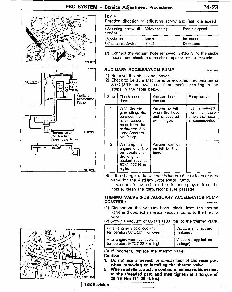
uxiliafy ccelerator ump
3Fu333 (for Auxiliary Accelerator Pump)
OVATE Rotation direction of adjusting screw and fast idle speed
Adjusting screw di- Valve opening rection
Clockwise Large Counterclockwise Small
Fast idle speed
Increases Decreases
(7) Connect the vacuum hose removed in step (3) to the choke opener and check that the choke opener cancels fast idle.
AUXILIARY ACCELERATION PUMP Nw=YAAb (1) Remove the air cleaner cover. (2) Check to be sure that the engine coolant temperature is
30°C (86°F) or lower, and then check according to the steps in the table below.
Step Check condi- Vacuum hose Pump nozzle tions Vacuum
1 With the en- Vacuum is felt Fuel is sprayed gine idling, dis- when the hose from the nozzle connect the end is covered when the hose black vacuum by a finger. is disconnected. hose from the carburetor Aux- iliary Accelera- tor Pump.
2 Warm-up the Vacuum cannot - engine until the be felt by the temperature of finger. the engine coolant reaches 50°C (122°F) or higher.
(3) If the change of the vacuum is incorrect, check the therm0 valve for the Auxilian/ Accelerator Pump. If vacuum is normal but fuel is not sprayed from the nozzle, clean the carburetor’s fuel passage.
THERM0 VALVE (FOR AUXILIARY ACCELERATOR PUMP CONTROL) NWFZA‘tL
(1) Disconnect the vacuum hose (black) from the therm0 valve and connect a manual vacuum pump to the therm0 valve.
(2) Apply a vacuum of 66 kPa (10.0 psi) to the therm0 valve.
When engine is cold [coolant temperature 30°C (86°F) or lower]
Vacuum is not applied (leakaae).
After engine warm-up [coolant temperature 50°C (122°F) or higher]
Vacuum is applied (no leakage).
(3) If incorrect, replace the therm0 valve. Caution 1. Do not use a wrench or similar tool at the resin part
when removing or installing the therm0 valve. 2. When installing, apply a coating of an anaerobic sealant
to the threaded part, and then tighten at a torque of 20-35 Nm (14-25 ftlbs.).
/ TSB Revision J

14-24 FBC SYSTEM - Service Adiustment Procedures
THROTTLE OPENER CONTROL SYSTEM FOR AIR CONDI- TIONER LOAD NwPGBBb
Inspection Condition Engine coolant temperature : 85 - 95°C (185 - 205°F) (I) Disconnect the vacuum-hose (yellow stripe) from the
throttle opener installed on the carburetor and connect a hand vacuum pump to the nipple.
(2) Check that the throttle opener rod is pulled up when vacuum is applied.
(3) Apply 67 kPa (10.0 psi) vacuum and check air tightness. ._ (4) Start the engine and close the vacuum hose (yellow stripe)
end with a finger to check vacuum when the air condition- er switch is turned on and off.
Air conditioners switch
Engine speed Hose end vacuum
OFF = Idle
Absent
Present
ON 1,200 mm or
more Absent
FUEL FILTER REPLACiMENT refer to GROUP 0 - Fuel filter (Replace)
iIh;FFILL LIMITER (TWO-WAY VALVE) REPLACE- NMFEAGI
(1) Remove the fuel filter hose protector. (2) Disconnect the vapor hoses, and then remove the overfill
limiter.
FUEL GAUGE UNIT AND PIPE ASSkMBiY RE- PLACEMENT NWFFAI (1) Remove the fuel tank cap and lower the fuel tank’s internal
pressure. (2) ;isixrnect the .harness connector from the fuel gauge
(3) Remove the fuel gauge unit installation screws, and then remove the fuel gauge unit and pipe assembly from the fuel tank.
/ TSB Revision
FBC SYSTEM - FBC System Inspection
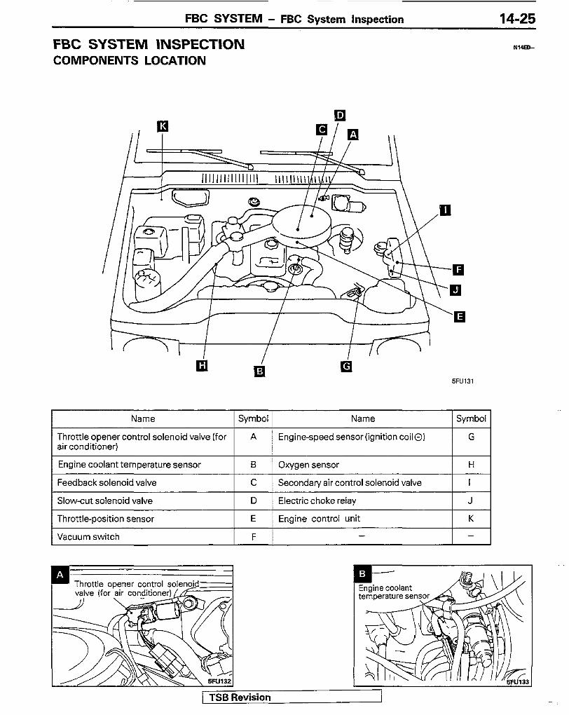
FBC SYSTEM INSPECTION COMPONENTS LOCATION
14-25
NMED-
5FU131
Name Symbol Name Symbol
Throttle opener control solenoid valve (for A Engine-speed sensor (ignition coil0) G air conditioner)
Engine coolant temperature sensor B Oxygen sensor H
Feedback solenoid valve C Secondary air control solenoid valve I
Slow-cut solenoid valve D Electric choke relay J
Throttle-position sensor E Engine control unit K
Vacuum switch F - -
[ TSB Revision

14-26 FBC SYSTEM - FBC System inspection
Throttle-Poskon sensor
Secondary air controzienoid valve -- -(
Vacuum switch
/ / f,

FBC SYSTEM - FBC System Inspection 14-27
Connect to ECU
1. Before removing or installing a part, disconnect the battery - terminal.
2. Before disconnecting battery terminals, turn off the igni- tion switch. Removal or connection of battery terminals during engine operation or with the ignition switch ON could cause erroneous operation of the Engine control unit or damage to semiconductors.
3. The control harnesses between Engine control unit and ignition coil [ -terminal] and between Engine control unit and oxygen sensor are shielded wires with shield ground- ed to the vehicle body in order to prevent ignition noises and radio interference. When the shielded wire is faulty, therefore, the control harness must be replaced.
4. When ECI checker is handled, pay attention to the following points. l Avoid rough operation of switches. l Do not subject ECI checker to shock and other external
forces, heat, etc. l Keep away water and oil. l Store ECI checker in a moisture- and dust-free place
and take steps to protect the checker from heat and vibration.
FBC SYSTEM INSPECTION (USE ECI CHECKER) NI4PDAG Inspection and maintenance of electric system in the FBC system can be made quickly by inspecting the Engine control unit input and output electric signals with the ECI checker and then by inspecting the component whose signal is abnormal and the harness between the component and the Engine control unit. Using the special tools (FBC Test Harness and ECI Checker), check the FBC system by the following procedure. Inspection Procedure: (I) Turn ignition switch to “LOCK”. (2) Remove the ECI cover. (3) Disconnect the Large harness connector and Small har-
ness connector from the Engine control unit. (4) Set check switch of the ECI checker to OFF. (5) Set select switch of the ECI checker to A. (6) Connect the FBC Test Harness to the connectors of the
ECI checker, and then connect the FBC Test Harness to the Engine control unit and harness connectors.
(7) Perform checks according to the FBC System Check Procedure chart.
(8) If checker shows any variance from specifications, check the corresponding sensor and related electrical wiring then repair or replacement.
(9) After repair or replacement, recheck with the ECI checker to confirm that the repair has corrected the problem.
(lO)Set check switch of the ECI checker to OFF. (1 l)Set ignition switch to “Lock”. (12)Disconnect connectors of the ECI checker and the FBC
Test Harness from the Engine control unit and the body side harness connectors.
(13)Connect the body side harness connectors to the Engine control unit.
(14)After completion of the above test make certain that the trouble has been eliminated on the road test.
1 TSB Revision
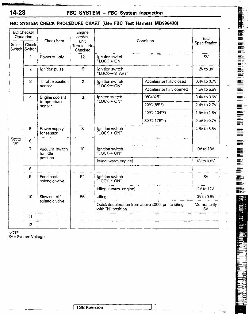
14-28 FBC SYSTEM - FBC System inspection
FBC SYSTEM CHECK PROCEDURE CHART (Use FBC Test Harness MD9994383
ECI Checker Operation
Select Check switch Switch
Check Item
Engine control
unit Terminal No.
Checked
Condition Test
Specification
I I 1 Power supply 12 Ignition switch “LOCK-- ON”
/ I 2 Ignition pulse 5 Ignition switch 2V to 8V “LOCK- START’
3 I I Throttle position 2
I I
Ignition switch Accelerator fully closed 0.4v to 0.N sensor “LOCK- ON”
Accelerator fully opened 4.5v to 5.5V
4 I I Engine coolant 3
I I
lgniton switch 0°C (32-F) 3.4v to 3.W temperature “LOCK-ON” sensor 20°C (68°F) 2.4Vtc 2.7V
5 Power supply 8 Ignition switch .’ 4.94 to 5.5v for sensor “LOCK-c ON”
Setto 6 ‘;4”
7 Vacuum switch 10 Ignition switch 9vto 13v for idle “LOCK-, ON” position
Idling (warm engine) ov to 0.w
9 Feed back 52 Ignition switch sv solenoid valve “LOCK-t ON”
Idling (warm engine) zvto 12v
10 Slow cut-off 56 idling OV to 0.6V solenoid valve -
Cluick deceleration from above 4000 rpm to idling Momentarily with “N” position sv
I 11
NOTE SV = System Voltage
1 TSB Revision
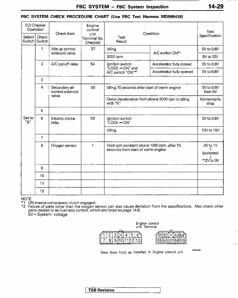
FBC SYSTEM - FBC System Inspection
FBC SYSTEM CHECK PROCEDURE CHART (Use FBC Test Harness MD998438)
ECI Checker Operation
;elect Check ;witcr I Switch
Engine control
unit Terminal No
Checked
57
Test Specification Check Item Condition
jet to “B”
Test Result
1 Idle up control solenoid valve +i A/Cswitch ON*’
2 A/C cut-off relay 54 Ignition switch “LOCK&ON” and A/C switch “ON””
Accelerator fully closed
Accelerator fully opened
OVto0.6V
OV to 0.6V
3
4 Secondary air control solenoid valve
58 Idling 70 seconds after start of warm engine ovto0.6v then SV
Quick deceleration from above 2000 rpm to idling with “N”
Momentarily drop
6 Electric choke relay
Ignition switch “LOCK-cON”
OV to 0.6V
Idling
8 Oxygen sensor Hold rpm constant above 1300 rpm, after 70 seconds from start of warm engine
ovto 1v
(pu&tesJ
‘22”to 3v
NOTE NOTE *I *I ON means compressor clutch engaged. ON means compressor clutch engaged. “2 “2 Failure of parts other than the oxygen sensor can also cause deviation from the specifications. Also check other Failure of parts other than the oxygen sensor can also cause deviation from the specifications. Also check other
parts related to air-fuel ratio control, which are listed on page 14-6. parts related to air-fuel ratio control, which are listed on page 14-6. SV= System voltage SV= System voltage
Engine control unit Terminal
View from front as installed in Engine control unit
1 TSB Revision

FBC SYSTEM - FBC System Inspection
16R1251
line coolant temperature isor
Sensor output
Sensor ground
olR0129
OlRo133
I
OlR0490
5FUOO75’
ENGINE COOLANT TEMPERATURE SENSOR NI~AAU INSPECTION
(1) Remove engine coolant temperature sensor from the intake manifold.
(2) With temperature sensing portion of engine coolant tempera- ture sensor immersed in hot water, check electrical resis- tance. The sensor should be held with its housing 3 mm (.I2 in.) away from the surface of the hot water.
Temperature “c 0
0 02)
20 68)
Resistance 60)
5.9
2.5
I 40 mw I 1.1 I I 80 (176) I 0.3 I
(3) If the resistance deviates greatly from the standard value, re- place the engine coolant temperature sensor.
lNSTAUAllON (I) Apply anaerobic sealant to threaded portion. (2) Install engine coolant temperature sensor and tighten it to
specified torque.
Sensor tightening torque : 20 - 40 Nm (14 - 29 ft. lb4 (3) Fasten harness connectors securely.
THROTTLE POSITION SENSOR INSPECTION
Nl4OEblC
(1) Disconnect the carburetor connector. (2) Measure resistance between terminal 4 (sensor power)
and terminal 8 (sensor ground).
Standard value : 3.5 - 6.5 K!A
(3) Connect an ohmmeter (pointer type) between terminal 8 (sensor ground) and terminal 3 (sensor output).
(4) Operate the throttle valve slowly from,idle position to the full open position and check that the resistance makes a smooth change proportionally with the throttle valve opening.
NOTE The resistance changes within the range from approx.0.5 ka to the value measured at step (2).
(5) If the resistance is out of specification or fails to change smoothly, replace the throttle position sensor.
TPS installation torque : 2.5 - 4.5 Nm (1.8 - 3.3 ft. Ibs.)
NOTE I Refer to P.1413 for the throttle position sensor adjusting procedure.
/ TSB Revision

FBC SYSTEM - FBC System Inspection 14-31
ENGlNE SPEED SENSOR (IGNITION COIL TERMINAL) Nwlcmb
INSPECTION Check that there is continuity between the ignition coil - terminal and the electronic control unit terminal 10.
NOTE Shake the harness connector to check for lurking open circuit.
OXYGEN SENSOR INSPECTION Caution 1. Before checking, warm up the ‘engine until engine
coolant temperature reaches 85 to 95” (185 to 205°F). 2. Use an accurate digital voltmeter. (1) Disconnect the oxygen sensor connector and connect a
voltmeter to the oxygen sensor connector. (2) While repeating engine racing, measure the oxygen
sensor output voltage.
Engine Oxygen sensor output voltage
Remarks
Racing Approx. 1 V Make air-fuel mixture richer by accelerator operation
NOTE For removal and installation of the oxygen sensor, refer to GROUP 11 - Exhaust Manifold.
Oxygen sensor installation torque : 40 - 50 Nm (30 - 36 ft. Ibs.)
VACUUM SWITCH INSPECTION
N14OlAB
(1) Disconnect the vacuum hose (green’ stripe) from the device box, and connect a manual vacuum pump to the device box nipple.
(2) Disconnect the vacuum switch connector (3) Apply negative pressure (vacuum) and check whether or
not there is continuity between the switch terminals.
(4) If there is a problem, remove the device box cover, and replace the vacuum switch assembly.
5FUOO73
/ TSB Revision
Vacuum gauge
26 kPa (3.9 psi) or lower
40 kPa (5.8 psi) or higher
Measured terminals Continuity
c8-B No (oat-L)
0 Yes (On)

14-32 FBC SYSTEM - FBC System Inspection
(Front view at carburetor side)
SFUOOM
(Front view at carburetor side)
FEEDBACK SOLENOID VALVE INSPECTION
NIUIOAaLI
(1) Disconnect the carburetor. connector. (2) Apply battery voltage (approx. 12V) between the solenoid
valve terminals and check that the solenoid valve operates with a click. If no click is heard, replace the solenoid valve.
NOTE For the feedback solenoid valve removal and inspection procedures, refer to CARBURETOR DISASSEMBLY AND REASSEMBLY, P.14-35.
SLOW CUT SOLENOID VALVE INSPECTION
NwoPAab
(1) Disconnect the carburetor_ connector. (2) Apply battery voltage (approx. 12V) between the solenoid
valve terminals and check that the solenoid valve operates with a click. If no click is heard, replace the solenoid valve.
NOTE For the slow.cut solenoid valve removal and inspection procedures, refer to CARBURETOR DlSASSEMEfLY AND REASSEMBLY, P.14-35.
THR0l-tLE OPENER CONTROL SOLENOID VALVE FOR AIR CONDITIONER NIuLmAa INSPECTION NOTE When disconnecting the vacuum hoses from the solenoid valve, put marks on the hoses for correct installation.
i (1) Disconnect the vacuum hoses (white stripe, yellow stripe) from the solenoid valve.
(2) Disconnect the harness connector. (3) Connect a hand vacuum pump to the nipple to which the
white stripe vacuum hose been connected.
(4) Apply vacuum and check air tightness for both when battery voltage is directly applied to the solenoid valve terminal and when no voltage is applied.
Battery voltage ~~ The other nipple Normal state of solenoid valve
Applied Open Vacuum leaks-
Closed with finger Vacuum is held
Not applied Open Vacuum is held z
(5) Measure the solenoid coil resistance.
Standard value : 40 - 46!3 [at 20°C (SSOF)]
1 TSB Revision jl .-z I
FBC SYSTEM - FBC System Inspection 14-33
2 Fz!zzkk 4
Ignition switch N.C. (W
3 Electric-choke *PTC heater
l f’TC heater: Positive Temperature Coefficient Heater
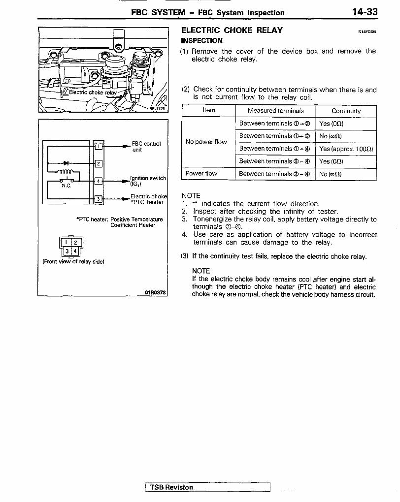
ELECTRIC CHOKE RELAY INSPECTION
Nw=ODB
(1) Remove the cover of the device box and remove the electric choke relay.
(2) Check for continuity between terminals when there is and is not current flow to the relay coil.
Item Measured terminals Continuity
Between terminals 0-Q Yes (M)
Between terminals 0-Q No power flow
No (ma)
Between terminals 0 * @ Yes (approx. 1 OOi2)
Between terminals @ - @ Yes (On)
Power flow Between terminals 0 - @ No (a-l)
NOTE 1. + indicates the current flow direction. 2. inspect after checking the infinity of tester. 3. Tonenergize the relay coil, apply battery voltage directly to
terminals 0. 4. Use care as application of battery voltage to incorrect
terminals can cause damage to the relay.
(3) If the continuity test fails, replace the electric choke relay.
NOTE If the electric choke body remains cool after engine start al- though the electric choke heater (PTC heater) and electric choke relay are normal, check the vehicle body harness circuit.
1 TSB Revision

14-34 FBC SYSTEM - Carburetor
CARBURETOR REMOVAL AND INSTALLATION
1619 Nm V-14 Ribs.
X-20 Nm 1 l-14 ft.lbs.
/ 8
\
Removal steps +* ++ 1. Air cleaner
I)* Adjustment of accelerator cable 2. Connection for accelerator cable 3. Connection for water hose 4. Connection for fuel vapor hose 5. Connection for vacuum hoses
Pre-removal Operation l Draining of the Coolant (Refer to
GROUP 0 - Coolant Replacement.)
++ +* +*
6. Connection for control harness connector 7. Connection for main hose 8. Connection for return hose 9. Carburetor
10. Gasket
NOTE (1) Tieverse the r&oval procedures to reinstail. (2) +I, Refer to “Service Points of Removal”. (3) ++ Refer to “Service Points of installation” (4) q : Non-reusable parts
038552
1 TSB Revision -
FBC SYSTEM - Carburetor
SERVICE POINTS OF REMOVAL 1. REMOVAL OF AIR CLEANER
Refer to GROUP 11 - Air cleaner.
14-35
NII(MSFlcb
7. DISCONNECTION OF MAIN HOSE/I. RETURN HOSE (1) Before disconnection of the fuel hose, remove the fuel
tank cap to lower the pressure in the fuel thank. (2) With the receiver placed under the fuel inlet fitting to
receive fuel left in the hose, remove fuel hose from the carburetor inlet nipple.
9. REMOVAL OF CARBURETOR NOTE When the carburetor is removed, keep it horizontally SO as not to spill fuel from the carburetor.
SERVICE POINTS OF INSTALLATION NludDAc . ADJUSTMENT OF ACCELERATOR CABLE FREE PLAY
Refer to P.l4-102.
1. INSTALLATION OF AIR FILTER Refer to GROUP 11 - Air cleaner.
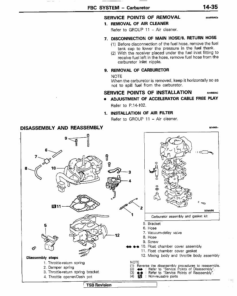
DISASSEMBLY AND REASSEMBLY
-12
I Carburetor assembly and gasket kit -... 5. tlractcet 6. Hose 7. Vacuum-delay valve 8. Hose 9. Screw
l + l + ‘10. Float chamber cover assembly 11. Float chamber cover gasket
Diassembly steps 1. Throttle-return spring 2. Damper spring 3. Throttle-return spring bracket 4. Throttle opener/Dash pot
1 TSB Revision
1’2. Mixing body and throttle body assembly
NOTE (1) Reverse the disassembly rocedures to reassemble.
8- (2) *I+ : Refer to ;Servjce o!nts of Disassembly’. 1Z31 + : Refer to Service Potnts of Reassembly
d : Non-reusable Parts

FBC SYSTEM - Carburetor
Disassembly steps
13. Pin
dir 16
k-15
14. Float 15. Needle valve
16. Needle valve seat 17. 0-rino
18. Packing 19. Retainer
41) +4 20. Feedback solenoid valve 21. O-ring 22. O-ring 23. Tube 24. Retainer
41) l + 25. Slow-cut solenoid valve 26. O-ring 27. O-ring 28. Plate
*e I)+ 29. Bimetal assembly 30. Packing 31. Connector 32. Cover 33. Diaphragm 34. Spring seat 35. Spring 36. Body
37. Spring 38. Diaphragm 39. Valve 40. Mixture control valve assembly 41. Gasket 42. Cover 43. Spring 44. Diaphragm 45. Body 46. Spring 47. Diaphragm 48. Bracket 49. Cover 50. Spring 51. Diaphragm 52. Body
41) I)+ 53. Main air jet (primary) l * l + 54. Pilot jet (primary) ae l + 55. Pilot jet (secondary)
56. Float chamber cover
(1) Reverse the disassembly procedures to reassemble. : (2) +e : Refer to ‘Y&vice Points of Disassembly”. (3) +* : Refer to “Service Points of Reassembly”. (4) q : Non-reusable park SF, ,153
/ TSB Revision

FBC SYSTEM - Carburetor 14-37
Disassembly steps +a 57. Steel ball ++ 58. Weight ++ 59. Ball +* 60. Plug ++ 61. O-ring ++ 62. Ball
+I) 63. Screw 64. Gasket
+e ++ 65. Main jet (primary) *+ +a 66. Main jet (secondary)
67. Hose
5FUOO70
72. Throttle (ever 73. Cam follower 74. Fast-idle adjustment screw 75. Free lever 76. Apartment plate 77. Idle-speed adjustment screw (SAS-2) 78. Spring 79. Secondary lever 80. Idle-speed adjustment screw (SAS-1) 81. Concealment plug 82. Mixture-adjustment screw 83. Throttle body
68. Mixing body 69. Vacuum hose 70. Depression chamber 71. Throttle-position sensor
NOTE (1) Reverse the disassem,bly procedures, to reassemble. \;I ;; : Refer to ,,Serv!ce Points of Drsassembly
: Refer to Service Pornts of Reassembly (4) q : Non-reusable parts
I SERVICE POINTS OF DISASSEMBLY NIu.lFAE Caution 1. Do not disassemble the following components at the
time of disassembly. (1) Choke valve, choke shaft and automatic choke
device (2) Inner venturi (3) Throttle valve and throttle shaft (4) Fuel inlet nipple
2. When loosening a Philips screw which has been firmly tightened, use a Philips screwdriver that is an exact fit for the screw.
TSB Revision i
;
14-38 FBC SYSTEM - Carburetor
Stopper portion Connector
in
Throttle position sensor terminals
s)
5fUlX i
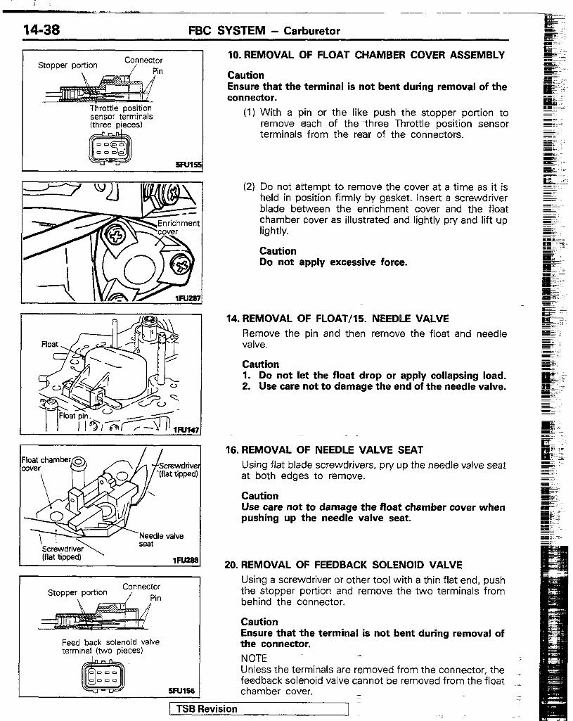
10. REMOVAL OF FLOAT CHAMBER COVER ASSEMBLY
Caution Ensure that the terminal is not bent during removal of the connector.
(1) With a pin or the like push the stopper portion to remove each of the three Throttle position sensor terminals from the rear of the connectors.
7--F- \
‘Needle valve C---4river
seat
Wd) ,R,% I ““II..C (flat tip(
Feed back solenoid valve terminal (two pieces)
(2) Do not attempt to remove the cover at a time as it is held in position firmly by gasket. insert a screwdriver blade between the enrichment cover and the float chamber cover as illustrated and lightly pry and lift up lightly.
Caution Do not apply excessive force.
14. REMOVAL OF FLOAT/15. NEEDLE VALVE Remove the pin and then remove the float and needle valve.
Caution 1. Do not let the float drop or apply collapsing load. 2. Use care not to damage the end of the needle valve.
16. REMOVAL OF NEEDLE VALVE SEAT Using flat blade screwdrivers, pry up the needle valve seat at both edges to remove.
Caution Use care not to damage the float chamber cover when pushing up the needle valve seat.
20. REMOVAL OF FEEDBACK SOLENOID VALVE
Using a screwdriver or other tool with a thin flat end, push the stopper portion and remove the two terminals from behind the connector.
Caution Ensure that the terminal is not bent during removal of the connector. NOTE Unless the terminals are removed from the connector, the feedback solenoid valve cannot be removed from the float .I chamber cover. 1 z
1 TSB Revision 1

FBC SYSTEM - Carburetor 14-39
I Slow cut solenoid Valve termin; (two pieces)
Bimetal assembly Terminal
SW158
R
25. REMOVAL OF SLOW CUT SOLENOID VALVE (1) Remove the retainer and pull out the slow cut solenoid
valve.
Cautioon When removing the valve, do not hold the leads but hold the body.
(2) Using a screwdriver or other tool with a thin flat end. push the stopper section and remove the two termi- nals from behind the connector.
Caution Ensure that the terminal is not bent during removal of the connector.
29. REMOVAL OF BIMETAL ASSEMBLY (1) Grind away the head of the two rivets of the bimetal
assembly using an hand grinder or other tool. remove the screw.
(2) Remove the plate, the bimetal assembly and the packing.
(3) Remove the remaining rivet bodies using a pin punch etc..
(4) Using a screwdriver or other tool with a thin fiat end, push the stopper section and remove the terminal from behind the connector.
Caution Ensure that the terminal is not bent during removal of the conector.
59. REMOVAL OF MAIN AIR JET (PRIMARY)/54. PILOT JET (PRIMARY)/55. PILOT JET (SECONDARY) (1) When removing the jets, use a screwdriver that is an
exact fit for their slot and work carefully to prevent damage.
FB Revision

FBC SYSTEM - Carburetor
Drill hole here at a 45” angle towards concealment plug I
Concealment Plug
e ing
hole
63. REMOVAL OF SCREW (1) Use a Phillips screwdriver that is an exact fit and work
carefully to prevent damage.
Caution Do not cause burrs to the recess in screw head as they could produce gap between throttle body and the manifold surface.
65. REMOVAL OF MAIN JET (PRIMARY)/66. MAIN JET [SECONDARY) When removing the jets, use a screwdriver that is an exact fit and work carefully to prevent damage.
81. REMOVAL OF CONCEALMENT PLUG (1) Clamp carburetor in a vice with idle mixture adjusting
screw facing up (protect gasket surface from vice jaws).
(2) Drill a 2 mm (5/64 in.) pilot hole in the casting surrounding the idle mixture adjusting screw then redrill the hole to 3 mm (l/8 in.).
(3) Insert a blunt punch into the hole and drive out plug.
INSPECTION GENERAL INSPECTION Check the following and repair or replace parts if necessary. (1) Check the fuel paths (jets) and air paths (jets or orifices)
for clogging. If clogged, wash thoroughly with cleaning solvent or detergent and blow by compressed air. Do not use metal wire or other metal pieces.
(2) Check the diaphragms for damage and cracks. (3) Check that the needle valve operates lightly. If the valve is
hard to slide or is binding. repair or replace. If there is overflow, poor valve to seat contact is suspected. Check thoroughly.
(4) Check the fuel inlet filter (located above the needle valve) for clogging and damage.
(5) Check the float operation. Check the float and lever for deformation and damage and replace if necessary. -
(6) Check operation of the throttle valve, choke valve and link. If they do not operate lightly, wash well and apply engine oil sparelingly to their shaft.
(7) Check the float chamber and main body for damage and cracks.
1 TSB Revision 1 -

FBC SYSTEM - Carburetor 14-41
-SLOW CUT SOLENOID VALVE OPERATION CHECK mm- (1) Apply battery voltage directly to the slow cut solenoid
valve terminals. (2) Check that the valve operates with a click.
SLOW CUT SOLENOID VALVE RESISTANCE MEASURE- MENT N14MGCAb
(1) Using a circuit tester, check that there is no continuity between the solenoid valve body and terminals.
(2) Measure resistance between the terminals.
Standard value : 48 - 6On [at 20°C (68”F)]
FEEDBACK SOLENOID VALVE OPERATION CHECK N~.IGD~~ (1) Apply battery boltage directly to the feedback solenoid
valve terminals. (2) Check that the valve operates with a click.
(3) Check that the jet is free from clogging.
( TSB Revision
14-42 FBC SYSTEM - Carburetor
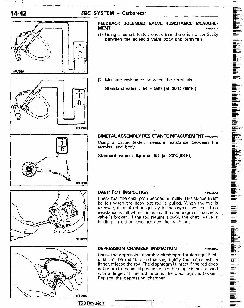
FEEDBACK SOLENOID VALVE RESISTANCE MEASURE- MENT NuMIIGEh -- t
3Ful76
(1) Using a circuit tester, check that there is no continuity between the solenoid valve body and terminals.
(2) Measure resistance between the terminals.
Standard value : 54 - m (at ZO’C (66”F)]
BIMETAL ASSEMBLY RESISTANCE MEASUREMENT NI,M=~~ Using a circuit tester, measure resistance between the terminal and body.
Standard value : Approx. 60 [at ZO’C(SVF]]
DASH POT INSPECTION NWMGGA
Check that the dash pot operates normally. Resistance must be felt when the dash pot rod is pulled. When the rod is released, it must return quickly to the orignal position. If no resistance is felt when it is pulled, the diaphragm or the check valve is broken. If the rod returns slowly, the check valve is binding. In either case, replace the dash pot.
DEPRESSION CHAMBER INSPECTiON B14MGHAa
Check the depression chamber diaphragm for damage. First, push up the rod fully and closing tightly the nipple with a finger, release the rod. The diaphragm is intact if the rod does not return to the initial position while the nipple is held closed with a finger. If the rod returns. the diaphragm is broken. .~ Replace the depression chamber.
1 TSB Revision
FBC SYSTEM - Carburetor 14-43
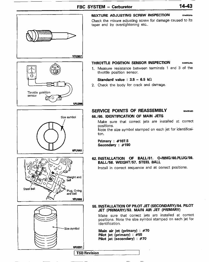
MIXTURE ADJUSTING SCREW INSPECTION Nl4MGlAb
Check the mixure adjusting screw for damage caused to its taper end by ovettightening etc..
Size symbol !
@ eFlJoo!2
I L
Size symbol k& lFu291
55. INSTALLATION OF PILOT JET (SECONDARY)/54. PILOT JET (PRIMARY)/53. MAIN AIR JET (PRIMARY) Make sure that correct jets are installed at correct positions. Note the size symbol stamped on each jet for identification.
Main air jet (primary) : #70 Pilot jet (primary) : #55 Pilot jet (secondary) : #70
[ TSfievision
THROTTLE POSITION SENSOR INSPECTION NI4MGJh
1. Measure resistance between terminals 1 and 3 of the throttle position sensor.
Standard value : 3.5 - 6.5 kn 2. Check the body for crack and damage.
SERVICE POINTS OF REASSEMBLY NI4MHAn 66./65. IDENTIFICATION OF MAIN JETS
Make sure that correct jets are installed at correct positions. Note the size symbol stamped on each jet for identificai- ton.
Primary : #107.5 Secondary : #I90
62. INSTALLATION OF BALL/61 . O-RING/60.PLUG/59. BALL/58. WEIGHT/57. STEEL BALL Install in correct sequence and at correct positions.
1
FBC SYSTEM - Carburetor
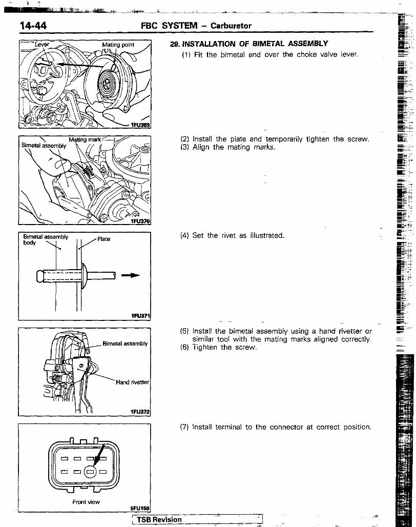
29. lNSTALLATION OF BIMETAL ASSEMBLY (1) Fit the bimetai end over the choke valve lever.
Bimetal assembly
Hand rivetter
II 7Wl I
wu3n
Front view SFU18 !!I 1 TSB Revision
(2) Install the plate and temporarily tighten the screw. (3) Align the mating marks.
(4) Set the rivet as illus_trated.
(5) install the bimetal assembly using a hand rivetter or - similar tool with the mating marks aligned correctly.
(6) Tighten the screw.
(7) Install terminal to the connector at correct position.
FBC SYSTEM - Carburetor 14-45
FBSV (yellow) SCm blue1 For Ips I
FBSV (red) SCd (red) ‘For bimetal
Front view assembly
5Ful6
Tps output (yellow greenhd
(omwl
TPS 0 (b&k/red)
SFUl62
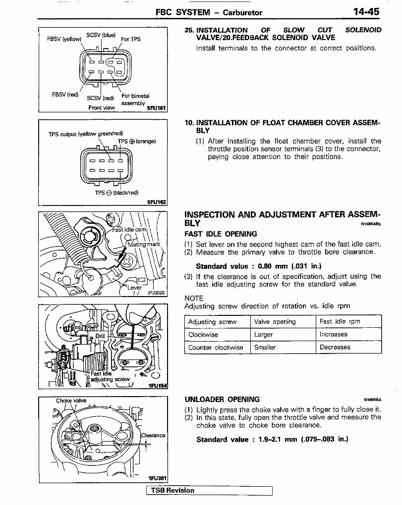
Choke vahre UNLOADER OPENING N14MIB.4
(1) Lightly press the choke valve with a finger to fully close it. (2) In this state, fully open the throttle valve and measure the
choke valve to choke bore clearance. rance
Standard value : 1.9-2.1 mm (.075-.083 in.)
,Fu3g,
IRevision
25. INSTALLATION OF SLOW CUT SOLENOID VALVE/;ZO.FEEDBACK SOLENOlD VALVE Install terminals to the connector at correct positions.
10. INSTALLATION OF FLOAT CHAMBER COVER ASSEM- BLY (1) After installing the float chamber cover, install the
throttle position sensor terminals (3) to the connector, paying close attention to their positions.
INSPECTION AND ADJUSTMENT AFTER ASSEM- BLY NI4r.ll*ab
FAST IDLE OPENING (1) Set lever on the second highest cam of the fast idle cam. (2) Measure the primary valve to throttle bore clearance.
Standard value : 0.80 mm (.031 in.) (3) If the clearance is out of specification, adjust using the
fast idle adjusting screw for the standard value.
NOTE Adjusting screw direction of rotation vs. idle rpm
1 Adjusting screw 1 Valve opening 1 Fast idle rpm
Clockwise Larger Increases I Counter clockwise Smaller Decreases I

14-46 FBC SYSTEM - Carburetor
Lever
Choke valve
ram
, , I \ , I
lFU30
(3) If the clearance is out of-specification, bend the throttle lever at illustrated portion to adjust the clearance to the standard value.
NOTE
Lever bending Clearance direction
Remarks
UP Larger
Down Smaller
CHOKE BREAKER
Caution
Poor response
Lower output Plug likely to get sooty
Nlawx
Check and adjust with the bimatal assembly removed. (1) Lightly press the choke valve with a finger to fully close it. (2) Push the choke breaker rod toward the diaphragm and
measure the choke valve to choke bore clearance.
Standard value : 1st stage : 2.3-2.5 mm (.OSl-.098 in.) 2st stage : 3.0-3.2 mm (.I18 -.I26 in.)
(3) If the clearance is out of-specification. adjust by bending the choke lever at illustrated portion.
NOTE
Lever bending Clearance direction
Remarks .-
Open Larger Poorer startability, more like- ly to stall
Close Smaller Plug likely to get sooty
CHOKE VALVE OPERATION NI4MHIIUr
(1) Operate the choke valve with a finger and check for play, incorrect operation and binding.
(2) If the choke fails to operate smoothly and lightly, wash around the choke valve.
(3) If the play is excessively large, replace the float chamber cover.
SECONDARY THROTTLE VALVE OPERATION NIUIIEh (1) Fully open the throttle valve and operate the secondary
throttle valve lever with a finger to check for play, incorrect operation and binding.
(2) If it fails to operate smoothly and lightly, wash and apply thin coat of engine oil to the shaft.
(3) If the play is excessively large, replace the throttle body.
PORTS Nwm=*
(I) Connect a hand vacuum pump to each port and check for clogging of the passage.
(2) If there is clogging, clean the port and then blow compressed air into the port.
1 TSB Revision
FBC SYSTEM - Carburetor 1447
Additional bleed air passage
Primary Primary throttle valve emulsion well
lFU371
5Fu37
Primary throttle valve
5Fu371
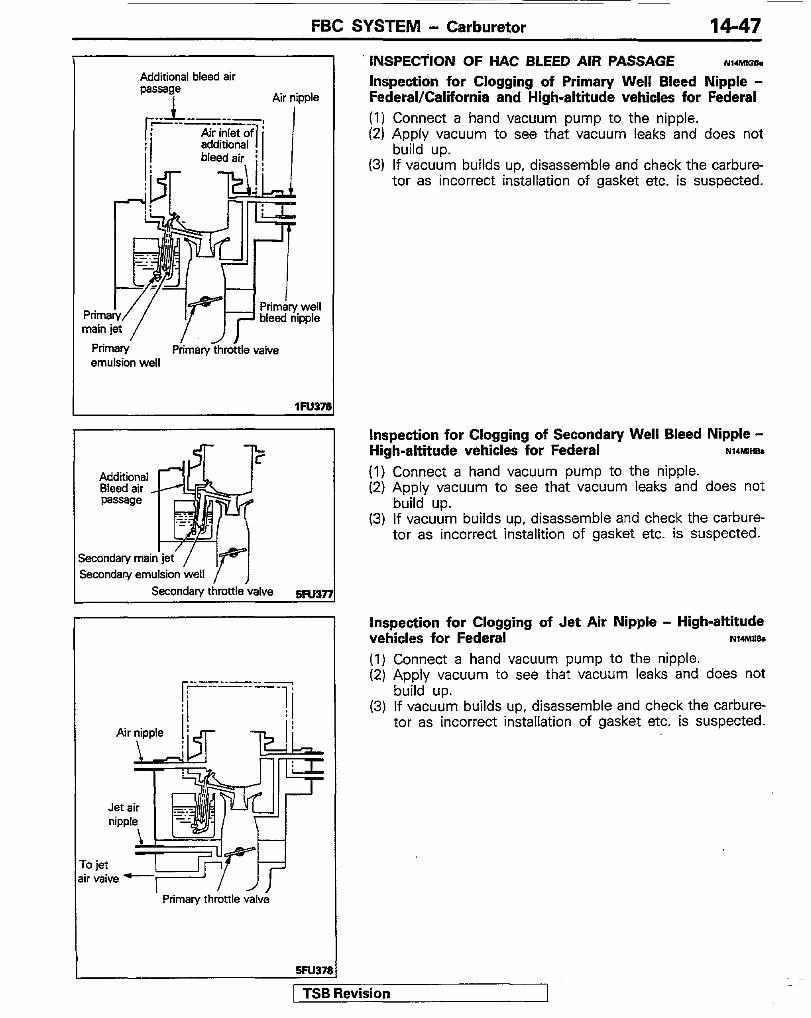
INSPECTiON OF HAC BLEED AIR PASSAGE Iy14MlGh Inspection for Clogging of Primary Well Bleed Nipple - Federal/California and High-altitude vehicles for Federal (I) Connect a hand vacuum pump to the nipple. (2) Apply vacuum to see that vacuum leaks and does not
build up. (3) If vacuum builds up, disassemble and check the carbure-
tor as incorrect installation of gasket etc. is suspected.
Inspection for Clogging of Secondary Well Bleed Nipple - High-altitude vehicles for Federal N14MIHaa
(1) Connect a hand vacuum pump to the nipple. (2) Apply vacuum to see that vacuum leaks and does not
build up. (3) If vacuum builds up, disassemble and check the carbure-
tor as incorrect installtion of gasket etc. is suspected.
Inspection for Clogging of Jet Air Nipple - High-altitude vehicles for Federal NI4M,Isa
(1) Connect a hand vacuum pump to the nipple. (2) Apply vacuum to see that vacuum leaks and does not
build up. (3) If vacuum builds up, disassemble and check the carbure-
tor as incorrect installation of gasket etc. is suspected.
1 TSB Revision

REMOVAL AND INSTALLATION
I Removal steps ++ ++ 1. Air cleaner 4* 2. Connection for the main hose 4* 3. Connection for the return hose 41) I)+ 4. Fuel pump
5. Gasket 6. Insulator
I j7.j Fgerse the removal procedures to reinstall;, : Refer to Servlce Points of Removal
(3) +a : Refer to “Service Points of Installation”. (4) q : Non-reusable parts.
14-48
FUEL PUMP
FBC SYSTEM - Fuel Pump
M-19 Nm 12-14 ftlbs.
SERVICE POINTS OF REMOVAL Nl4HsACb 1. REMOVAL OF AIR CLEANER
Refer to GROUP1 1 - Airrcleaner. 2. DiSCONNECTiON OF MAIN HOSE/B. RETURN HOSE
Before disconnection of the fuel hose, remove the fuel tank cap to lower the pressure in the fuel tank.
4. REMOVAL OF FUEL PUMP (I) Turn the crankshaft to place No. 1 cylinder at top dead
center on compression stroke.
NOTE The above operation places the lift of fuel pump stroke at the minimum positon, resulting in ease of fuel pump removal.
/ TSB Revision
FBC SYSTEM - Fuel Pump 14-49
,
+Front of engine
5ENOl6 I
I 5EN016 1
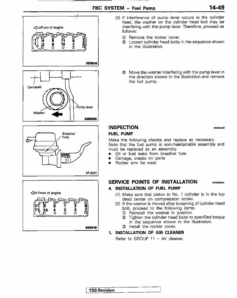
(2) If interference of pump lever occurs in the cylinder head, the washer on the cylinder head bolt may be interfering with the pump lever. Therefore, proceed as follows: 0 Remove the rocker cover. 0 Loosen sylinder head bolts in the sequence shown
in the illustration.
0 Move the washer interfering with the pump lever in the direciton shown in the illustration and remove the furl pump.
INSPECTION FUEL PUMP
NUHCAC
Make the following checks and replace as necessary. Note that the fuel pump is non-maintainable assembly and must be replaced as an assembly. l Oil or fuel leaks from breather hole l Damage, cracks on parts l Rocker arm for wear
SERVICE POINTS OF INSTALLATION N14HDIW 4. INSTALLATION OF FUEL PUMP
(I) Make sure that piston in No. 1 cylinder is in the top dead center on compression stroke.
(2) If the washer is moved after loosening of cylinder head bolt, proceed to the following items. 0 Reinstall the washer in position. @I Tighten the cylinder head bolts to specified torque
in the sequence shown in the illustration. 8 install the rocker cover.
1. INSTALLATION OF AIR CLEANER Refer to GROUP 11 - Air cleaner.
1 TSB Revision

FBC SYSTEM - Fuel Tank
FUEL TANK REMOVAL AND INSTALLATION YI4GA.A
Pm-removal Operation l Draining of the Fuel.
Post-installation Operation l Supplying of the Fuel.
18 18 10 : 1 Nm 0.7 ft.lbs.
I 9 4 18 \ t-. n
12 \ ‘P I
13 16
Ramoval steps
\ l&ONm 11-14 ftkls. 3
.- &C-
1. Drain plug 2. Fuel filler cap 3.
++ 4. I)+ 5.
6.
Fuel filler hose protector Vapor hose Check valve Overfill limiter (Two-way valve) Clamp assembly Fuel filler hose Breather hose
1. MI 8. I)+ 9.
14, 15. 16. 17. 18. 19.
Fuel gauge unit connector connection Fuel tank assembly mounting nuts Fuel tank Pipe assembly Separator tanks Fuel tank protector
10. Packing 11. Fuel filler neck
*+ 12. Main hose ++ 13. Return hose
NOTE (1) Reverse the removal. procedures to reinstall. (2) +* : Refer to “Service Points of Installation”.
( TSB Revision
FBC SYSTEM - Fuel Tank 14-51 .
lNSPECTlON NWGCAGf l Check the hoses and the pipes for crack or damage. l Check the fuel tank cap for malfunction. l Check the fuel tank for deformation, corrosion or crack. l Check the fuel tank for dust or foreign material.
NOTE If the inside of the fuel tank is to be cleaned, use any one of the following: (I) Kerosene (2) Trichloroethylene (3) A neutral emulsion type detergent
e Check the in-tank fuel filter for damage or clogging. l Check the check valve for malfunction.
CHECKING OVERFILL LIMITER (TWO-WAY VALVE) A simple way of inspection, however, may be adopted in which the overfill limiter is removed and then air is lightly blown into either the inlet or outlet. If the air passes after a slight resistance, overfill limiter is in good condition.
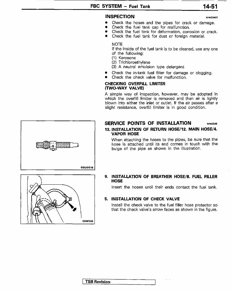
SERVICE POINTS OF INSTALLATION NIGOAE 13. INSTALLATION OF RETURN HOSE/lZ. MAIN HOSE/4.
VAPOR HOSE When attaching the hoses to the pipes, be sure that the hose is attached until its end comes in touch with the bulge of the pipe as shown in the illustration.
9. INSTALLATION OF BREATHER HOSE/8. FUEL FILLER HOSE Insert the hoses until their ends contact the fuel tank.
5. INSTALLATION OF CHECK VALVE Install the check valve to the fuel filler hose protector so that the check valve’s arrow faces as shown in the figure.
TSB Revision

FBC SYSTEM - Fuel Line and Vapor Line
FUEL LINE AND VAPOR LINE
1. Fuel filter clamp 2. Fuel filter
+a 3. Main hose l + 4. Return hose
5. Canister 6. Canister holder
l * 7. Vapor hose 8. Fuel vapor pipe 9. Stay
REMOVAL AND INSTALLATION Hl4KA-A
10. Fuel purge hose 11. Purge control valve 12. Fuel vapor pipe 13. Fuel main pipe 14. Fuel return pipe
NOTE ++ : Refer To “Service Points of Installation”.
1 TSB Revision

FBC SYSTEM - Fuel Line and Vapor Line 14-53
t To carburetor nd therm0 valve
To air filter
From canister
99u9919
-INSPECTION WI4KW l Check the fuel hoses and pipes for cracks, bends,
deformation, deterioration or clogging. l Check the fuel filter for clogging or damage. l Check the canister for clogging or damage. CHECKING PURGE CONTROL VALVE (1) Make sure that the cooling water is at a temperature
between 80 and 90°C (180 and 190°F). (2) Disconnect the purge control hose from the air cleaner
and blow into the purge hose. If the valve is not open, its operation is normal. Then start the engine and increase the engine speed to 1,500 to 2,000 rpm and blow into the purge hose. If the valve is not open, check for clogged or broken vacuum hose, or malfunctioning therm0 valve.
SERVICE POINTS OF INSTALLATION NI4KDAD 7. INSTALLATION OF VAPOR HOSE/4. RETURN HOSE/B.
MAIN HOSE When attaching the hose to the pipes, be sure that the hose is attached unit1 its end comes in touch with the bulge of the pipe as shown in the illustration.
1 TSB Revision