clutch - pajero 4x4 · 2001-03-26 · clutch - troubleshooting / service adjustment procedures 6-5...
TRANSCRIPT
6-I
CLUTCH CONTENTS NCSAA-
CLUTCH DISC ................................................... 73 Service Specifications ................. . ................. 2
CLUTCH MASTER CYLINDER AND TUBE 9 Torque Specifications ............................ ._ ...... 3
.......
CLUTCH PEDAL TROUBLESHOOTING ....................................... 4
................................................ 7 Clutch Chattering
CLUTCH RELEASE CYLINDER ......................... 11 Clutch Dragged (Clutch did not Release)
CLUTCH RELEASE FORK Clutch Noisy
. . . . . . . . . . . . . . . . . . . . . . . . . . . . . . . . . 15 Clutch Operation Erratic or Rough
SERVICE ADJUSTMENT PROCEDURES ......... 5 Clutch Slipping Bleeding ........................................................ 6 Difficult Gear Shifting Clutch Pedal Inspection and Adjustment ...... 5 (Gear Noise During Shifting)
SPECIFICATIONS 2 Hard Pedal Effort
............................................. General Specifications ................................... 2 Lubricants ...................................................... 3
CAUTION When servicing clutch assemblies or components, do NOT create dust by sanding, grinding or by cleaning clutch parts with a dry brush or with compressed air. (A water dampened cloth should be used.) The clutch disc contains “Asbestos Fibers” which can become airborne if dust is created during service operations. Breathing dust contain- ing “Asbestos Fibers” may cause serious bodily harm.
6-2 CLUTCH - Specifications
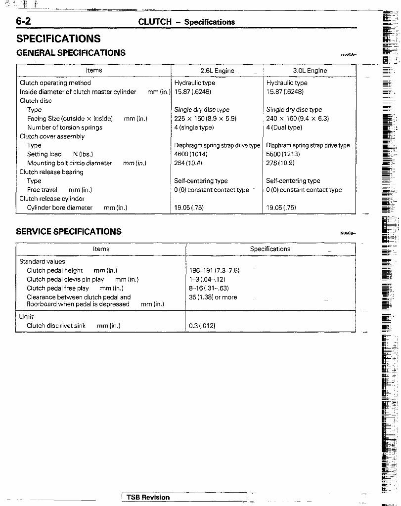
SPECIFICATIONS GENERAL SPECIFICATIONS
I
Items
Clutch operating method Inside diameter of clutch master cylinder mm (in. Clutch disc
Type Facing Size (outside x inside) mm (in.) Number of torsion springs
Clutch cover assembly
Type Setting load N (Ibs.) Mounting bolt circle diameter mm (in.)
Clutch release bearing
Type Free travel mm (in.)
Clutch release cylinder Cylinder bore diameter mm (in.)
SERVICE SPECIFICATIONS
2.6LEngine
Hydraulic type Hydraulic type 15.87 (6248) 15.87 r.6248)
Single dry disc type 225 x 150 (8.9 x 5.9) 4 (single type)
Single dry disc type 240 x 160 (9.4 x 6.3) 4 (Dual type)
Diaphragm spring strap drive type 4600(1014) 264(10.4)
Diaphram spring strap drive type 5500(1213) 276(10.9)
Self-centering type 0 (0) constant contact type
19.05 (75)
Self-centering type 0 (0) constant contacttype
19.05 (.75)
T 3.OL Engine
Items Specifications
Standard values Clutch pedal height mm (in.) 186-l 91 (7.3-7.5) Clutch pedal clevis pin play mm (in.) l-3 (.04-.I21 Clutch pedal free play mm (in.) 8-16 (.31-.63) Clearance between clutch pedal and 35 (1.38) or more floorboard when pedal is depressed mm (in.)
Limit Clutch disc rivet sink mm (in.) 0.3(.012)
. .-
TSB Revision
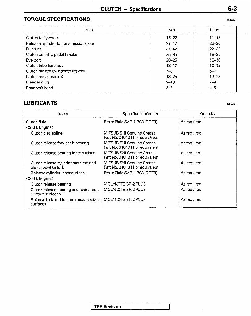
TORQUE SPECIFICATIONS
Items
Clutch to flywheel Release cylinder to transmission case Fulcrum Clutch pedal to pedal bracket Eye bolt Clutch tube flare nut Clutch master cylinderto firewall Clutch pedal bracket Bleeder plug Reservoir band
Nm
15-22 31-42 31-42 25-35 20-25 13-17 7-8 18-25 8-13 5-7
NOSVS
ft.lbs.
11-15 22-30 2230 18-25 15-18 lo-12 5-7 13-18 7-8 4-5
CLUTCH - Specifications 6-3
LUBRICANTS NO&CD-
Items Specified lubricants Quantity
Clutch fluid Brake Fluid SAE J1703 (DOT3) As required <2.6 L Engine>
Clutch disc spline MITSUBISHI Genuine Grease As required Part No. 0101011 or equivalent
Clutch release fork shaft bearing MITSUBISHI Genuine Grease As required Part No. 0101011 or equivalent
Clutch release bearing inner surface MITSUBISHI Genuine Grease As required Part No. 0101011 or equivalent
Clutch release cylinder push rod and MITSUBISHI Genuine Grease As required clutch release fork Part No.0101011 orequivalent Release cylinder inner surface Brake Fluid SAE J1703 (DOT3) As required
C3.0 L Engine> Clutch release bearing MOLYKOTE BR-2 PLUS As required Clutch release bearing and rocker arm MOLYKOTE BR-2 PLUS As required contact surfaces Release fork and fulcrum head contact MOLYKOTE BR-2 PLUS As required surfaces
rTSB Revision
6-4
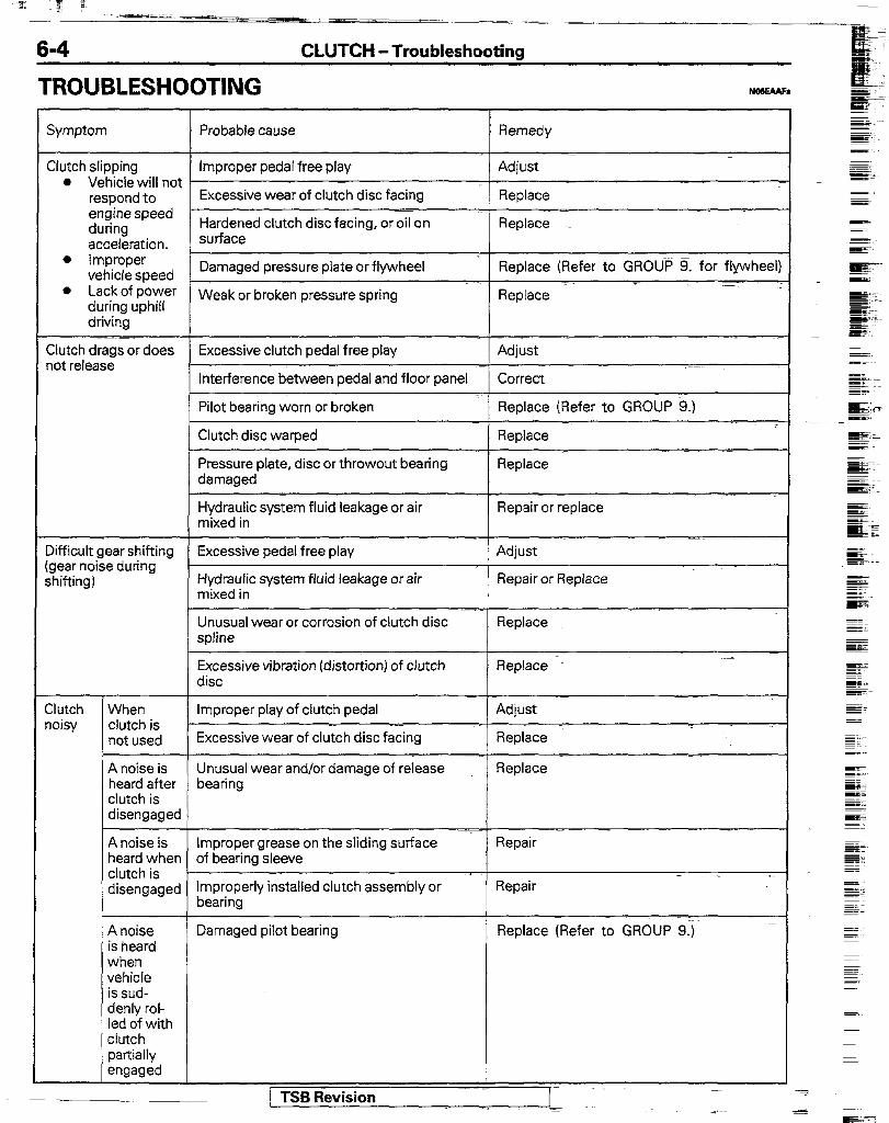
TROUBLESHOOTING
CLUTCH -Troubleshooting
Symptom Probable cause Remedy
Clutch slipping Improper pedal free play Adjust l Vehicle will not
respond to Excessive wear of clutch disc facing Replace engine speed ~~ during Hardened clutch disc facing, or oil on Replace _ acceleration. surface
l improper vehicle speed Damaged pressure plate or flywheel Replace (Refer to GROUP 9. for flywheel:
l Lack of power during uphill
Weak or broken pressure spring Replace
driving
Clutch drags or does Excessive clutch pedal free play Adjust _ lot release
Interference between pedal and floor panel Correct
Pilot bearing worn or broken Replace (Refer to GROUP 9.) -
Clutch disc warped Replace
Pressure plate, disc or throwout bearing Replace damaged
~~ Hydraulic system fluid leakage or air mixed in
Repair or replace
Xfficult gear shifting Excessive pedal free play gear noise during shifting) Hydraulic system fluid leakage or air Repair or Replace
mixed in
Unusual wear or corrosion of clutch disc spline
Replace
Excessive vibration (distortion) of clutch Replace disc
- :lutch When Improper play of clutch pedal Adjust noisy clutch is
not used Excessive wear of clt%h disc facing = Replace
A noise is Unusual wear and/or damage of release Replace heard after bearing clutch is disengaged
A noise is Improper grease on the sliding surface Repair heard when of bearing sleeve clutch is disengaged Improperly installed clutch assembly or Repair -
bearing
A noise Damaged pilot bearing ’ Replace (Refer to GROUP 9.) is heard when vehicle is sud- denly rol- led of with clutch partially engaged
I 7-c.” n-..:-:-- I -
CLUTCH - Troubleshooting / Service Adjustment Procedures 6-5
Symptom
Clutch chatters
Hard pedal effort
Probable cause
Facing hardened
Facing stained with oil or grease
Weak or broken disc damper springs
Improper facing contact or disc runout
Pressure plate or flywheel warped
Loose engine mounting
Improper lubrication of clutch pedal shaft
Remedy
Replace
Repair or replace
Replace
Replace
Replace (Refer to GROUP 9. for flywheel)
Repair or replace (Refer to GROUP 9.)
Repair
Improper lubrication of clutch disc spline
Repair
improper lubrication of clutch release lever shaft
Repair
Improper lubrication of front bearing retainer
Facing stained with grease or oil
Facing worn or rivet loose
Torsion spring deteriorated or broken
Improper lubricant on clutch pedal pivot
Repair (Refer to GROUP 21.)
Clutch operation erratic or rough
Repair or replace
Replace
Replace
Lubricate
L
1 i I
t
Clutch pedal height Clutch pedal clevis pin play SERVICE ADJUSTMENT PROCEDURES
CLUTCH PEDAL INSPECTION AND ADJUSTME!&
dehicles without VI ah n&o-cruise control cr ui system
licles with auto- se control system
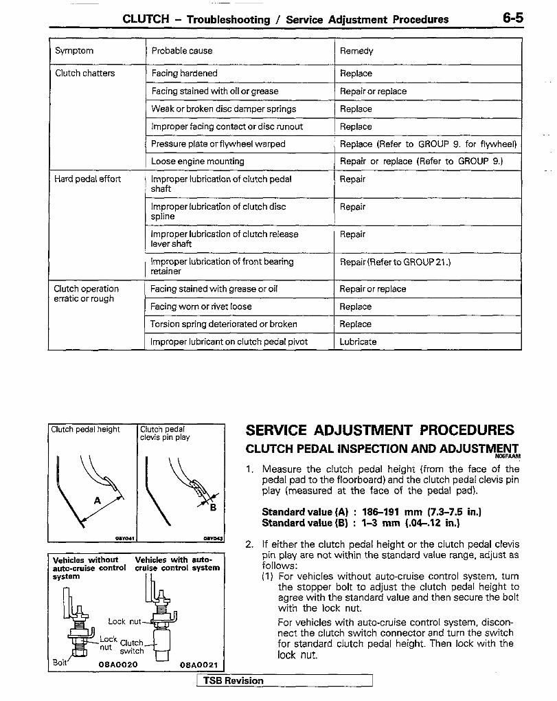
1. Measure the clutch pedal height (from the face of the pedal pad to the floorboard) and the clutch pedal clevis pin play (measured at the face of the pedal pad).
Standard value (A) : 185-191 mm (7.3-7.5 in.) Standard value (B) : l-3 mm (.O&.lZ in.)
2. If either the clutch pedal height or the clutch pedal clevis pin play are not within the standard value range, adjust as follows: (I) For vehicles without auto-cruise control system, turn
the stopper bolt to adjust the clutch pedal height to agree with the standard value and then secure the bolt with the lock nut. For vehicles with auto-cruise control system, discon- nect the clutch switch connector and turn the switch for standard clutch pedal height. Then lock with the lock nut.
levision
CLUTCH - Service Adjustment Procedures
oawa29
Clutch pedal free play Distance between the clutch pedal and the floorboard when the
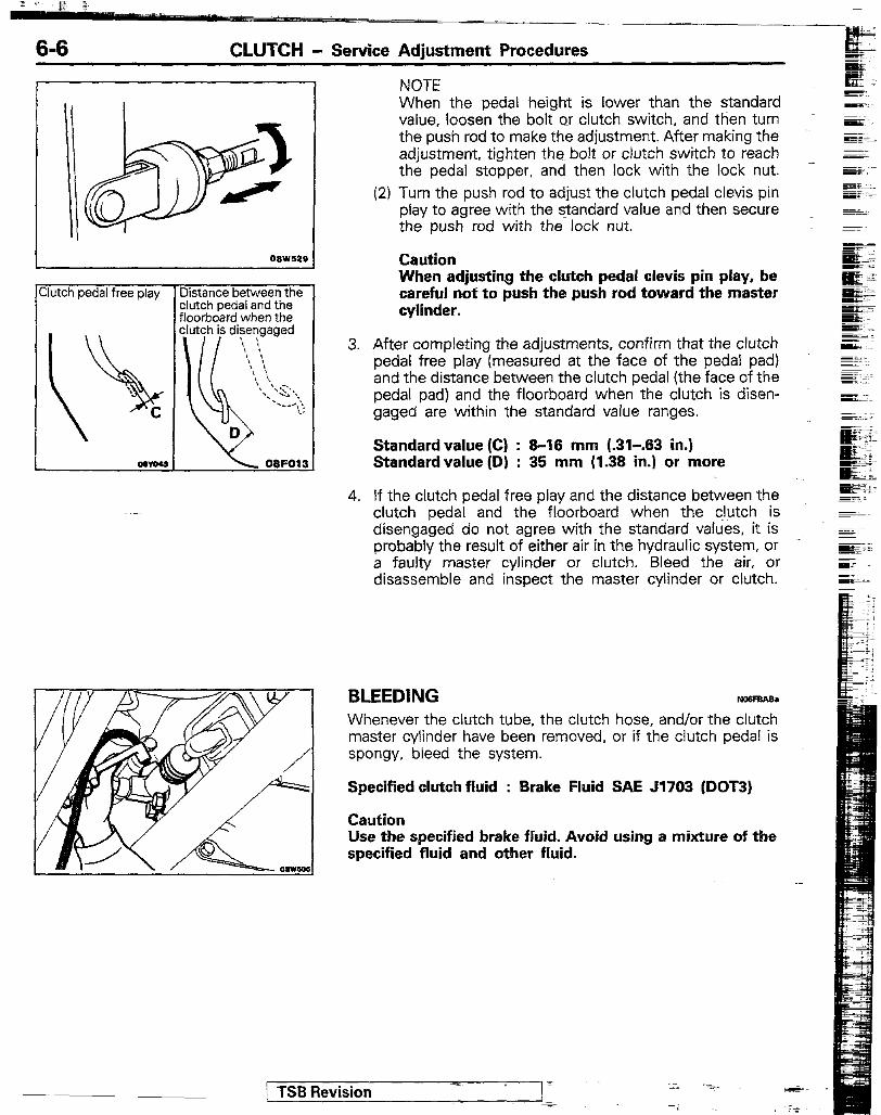
NOTE When the pedal height is lower than the standard value. loosen the bolt or clutch switch, and then turn the push rod to make the adjustment. After making the adjustment, tighten the bolt or clutch switch to reach the pedal stopper, and then lock with the lock nut.
(2) Turn the push rod to adjust the clutch pedal clevis pin play to agree with the standard value and then secure the push rod with the lock nut.
Caution When adjusting the clutch pedal clevis pin play, be careful not to push the push rod toward the master cylinder.
3. After completing the adjustments, confirm that the clutch pedal free play (measured at the face of the pedal pad) and the distance between the clutch pedal (the face of the pedal pad) and the floorboard when the clutch is disen- gaged are within the standard value ranges.
Standardvalue (C) : 8-16 mm (.31-.63 in.) Standard value (D) : 35 mm (1.38 in.) or more
4. If the clutch pedal free play and the distance between the clutch pedal and the floorboard when the clutch is disengaged do not agree with the standard values, it is probably the result of either air in the hydraulic system, or a faulty master cylinder or clutch. Bleed the air, or disassemble and inspect the master cylinder or clutch.
BLEEDING - Whenever the clutch tube, the clutch hose, and/or the clutch master cylinder have been removed, or if the clutch pedal is spongy, bleed the system.
Specified clutch fluid : Brake Fluid SAE 51703 (DOT3)
Caution Use the specified brake fluid. Avoid using a mixture of the specified fluid and other fluid.
/ TSB Revision
CLUTCH - Clutch Pedal <2.6L Engine>
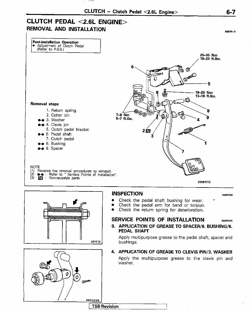
CLUTCH PEDAL <2.6L ENGINE> REMOVAL AND INSTALLATION
6-7
NWA-0
,
Post-installation Operation l Adjustment of Clutch Pedal
(Refer to P.&5.) 25-35 Nm
Removal steps 1. Return spring 2. Cotter pin
++ 3. Washer +*I 4. Clevis pin
5. Clutch pedal bracket ++ 6. Pedal shaft
7. Clutch pedal ++ 8. Bushing ++ 9. Spacer
NOTE (1) Reverse the removal procedures to reinstall. (21 +a : Refer to * Service Points of Installation”. (3) m : Non-reusable parts
08W510
INSPECTION NWPCAC l Check the pedal shaft bushing for wear. l
l Check the pedal arm for bend or torsion. l Check the return spring for deterioration.
SERVICE POINTS OF INSTALLATION ?wPDAR 9. APPLICATION OF GREASE TO SPACER/8. BUSHING/G.
PEDAL SHAFT Apply multipurpose grease to the pedal shaft, spacer and bushings.
4. APPLICATION OF GREASE TO CLEVIS PIN/3. WASHER Apply the multipurpose grease to the clevis pin and washer.
1 TSB Revision
6-8 CLUTCH - Clutch Pedal <3.OL Engine>
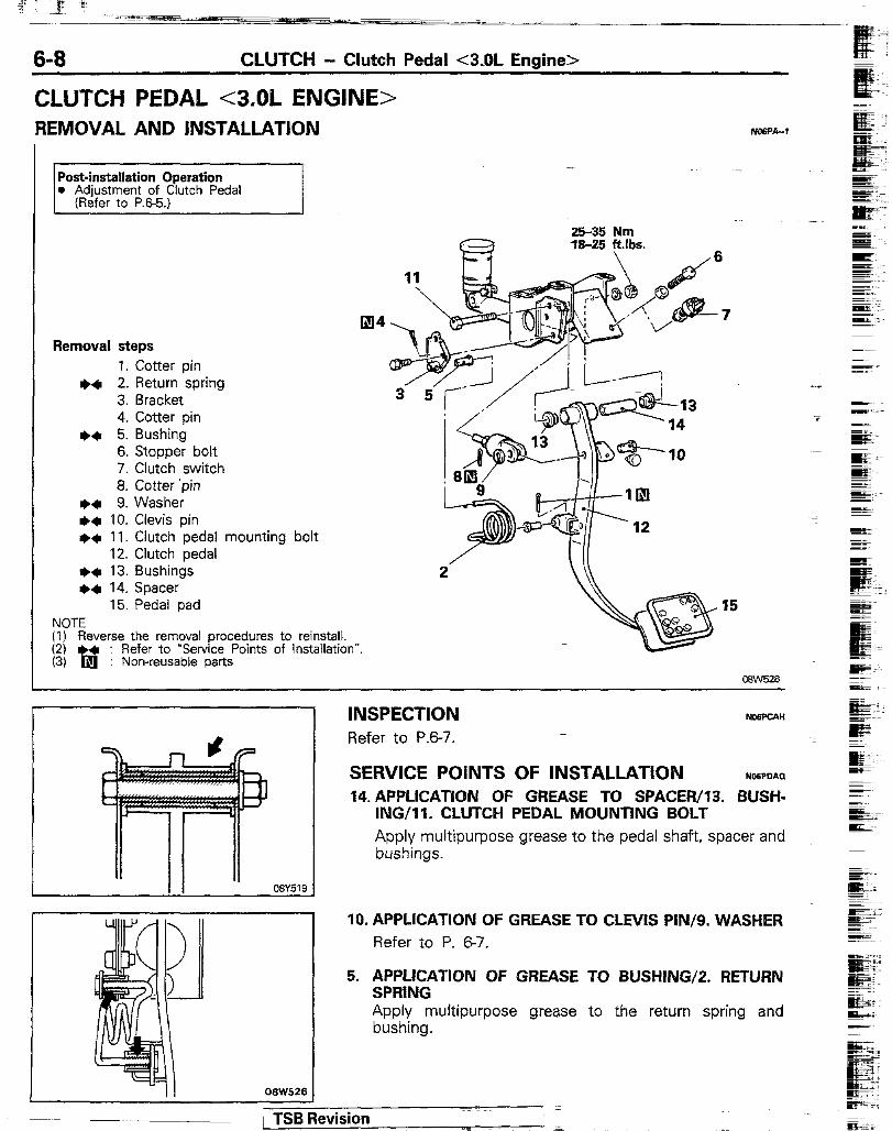
CLUTCH PEDAL <3,OL ENGINE> REMOVAL AND INSTALLATION
Post-installation Operation l Adjustment of Clutch Pedal
(Refer to P.65.)
Removal steps 1. Cotter pin
+* 2. Return spring 3. Bracket 4. Cotter pin
+a 5. Bushing 6. Stopper bolt 7. Clutch switch 8. Cotter ‘pin
+a 9. Washer +* 10. Clevis pin ++ 11. Clutch pedal mounting bolt
12. Clutch pedal I)+ 13. Bushings l a 14. Spacer
15. Pedal pad NOTE (1) Reverse the removal procedures to reinstall. (2) + : Refer to “Service Points of Installation”. (3) b : Non-reusable parts
25-35 Nm
r h%k!li
INSPECTION Refer to P.B-7.
SERVICE POINTS OF INSTALLATION No6PDPI(I 14. APPLICATION OF GREASE TO SPACER/lB. BUSH-
ING/II. CLUTCH PEDAL MOUNTING BOLT Apply multipurpose grease to the pedal shaft, spacer and bushings.
IO. APPLICATION OF GREASE TO CLEVIS PIN/g. WASHER
Refer to P. 67.
5. APPLICATION OF GREASE TO BUSHING/2. RETURN SPRING Apply multipurpose grease to the return spring and bushing.
1 TSB Revision
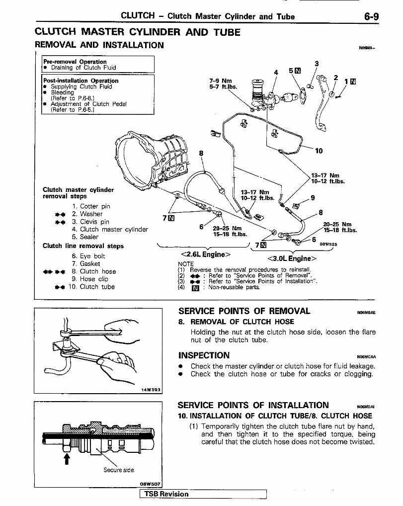
CLUTCH - Clutch Master Cylinder and Tube 6-9 CLUTCH MASTER CYLINDER AND TUBE REMOVAL AND INSTALLATION ?aeMez-
Pre-removal Operation , 0 Drainina of Clutch Fluid
Post-installation Operation l SupDlvina Clutch Fluid
4. Clutch ‘master cylinder 5. Sealer
Clutch master cylinder removal steps
1. Cotter pin l e 2. Washer I)* 3. Clevis pin
6’ 20-i5 Nm 15-18 ftlbs.
\ - / gine> Y
-5-2 nl iknin-> c2.6L- ” NOTE
.Y.“b .d.~..m-’
moval procedures to reinstall. (I* : Heter to “Service Points of RemovaI”. )* : Refer to “Service Points of Installation” q : Non-reusable parts.
Clutch line removal steps
6. Eye bolt 7. Gasket
+I) l * 8. Clutch hose 9. Hose clip
I)+ 10. Clutch tube
SERVICE POINTS OF REMOVAL NlMBAE 8. REMOVAL OF CLUTCH HOSE
Holding the nut at the clutch hose side, loosen the flare nut of the clutch tube.
iNSPECTION NOM- l Check the master cylinder or clutch hose for fluid leakage. l Check the clutch hose or tube for cracks or clogging.
14W593
SERVICE POINTS OF INSTALLATION NWMOAI 10. INSTALLATION OF CLUTCH TUBE/8. CLUTCH HOSE
(1) Temporarily tighten the clutch tube flare nut by hand, and then tighten it to the specified torque, being careful that the clutch hose does not become twisted.
Se&e side I
TSB Revision 1
6-10 CLUTCH - Clutch Master Cvlinder and Tube
(2) Connect the clutch hose to the release cylinder at the stepped portion shown in the illustration.
(3) After tightening the clutch tube flare nut and eye bolt, check to be sure there is no leakage of the clutch fluid.
3. APPLICATION OF GREASE TO CLEVIS PIN/2. WASHER Refer to P. 6-7.
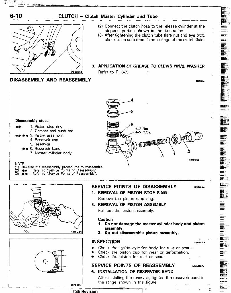
DISASSEMBLY AND REASSEMBLY FmsNA-
I
Disassembly steps
++ 1. Piston stop ring 2. Damper and push rod
+I) I)+ 3. Piston assembly 4. Reservoir cap 5. Reservoir
I)+ 6. Reservoir band 7. Master cylinder body
NOTE i (I) Reverse the disassembly procedures to reassemble (2) +e : Refer to “Service Points of Disassembly”. (3) l)a : Refer to “Service Points of Reassembly”.
SERVICE POINTS OF DISASSEMBLY 1. REMOVAL OF PISTON STOP RING
Remove the piston stop ring. 3. REMOVAL OF PISTON ASSEMBLY
Pull out the piston assembly.
Caution 1. Do not damage the master cylinder body and piston
assembly. 2. Do not disassemble piston assembly.
INSPECTION NOWCAB l Check the inside cylinder body for rust or scars. l Check the piston cup for wear or deformation. l Check the piston for rust or scars.
SERVICE POINTS OF REASSEMBLY Ncaow38 6. INSTALLATION OF RESERVOIR BAND
After installing the reservoir, tighten the reservoir band in the range shown in the-:figure.
/ TSBRevision 7 -
CLUTCH - Clutch Master Cylinder and Tube I Clutch ~ekase Cylinder 6-11
05Y51
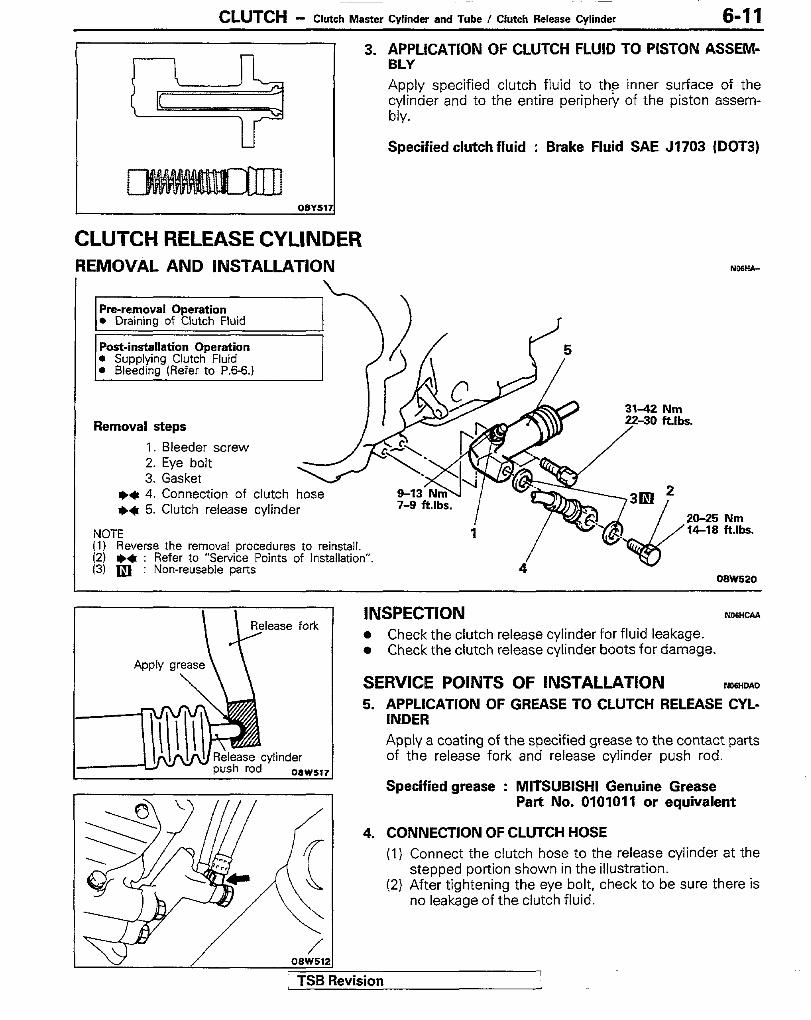
CLUTCH RELEASE CYLINDER REMOVAL AND INSTALLATION
3. APPLICATION OF CLUTCH FLUID TO PISTON ASSEM- BLY Apply specified clutch fluid to the inner surface of the cylinder and to the entire periphery of the piston assem- bly.
Specified clutch fluid : Brake Fluid SAE J1703 (DOT3)
Pre-removal Operation l Draining of Clutch Fluid
Post-installation Operation l Supplying Clutcti Fluid 0 Bleeding (Refer to P.B-6.)
Removal steps 1. Bleeder screw 2. Eye bolt 3. Gasket
&KIz
l * 4. Connection of clutch hose l a 5. Clutch release cylinder 7-9 ftlbs.
NOTE (1) Reverse the removal procedures to reinstall. (2) I)* : Refer to “Service Points of Installation”. (3) q : Non-reusable parts
Ribs.
20-25 ‘14-18 ES.
08W520
INSPECTION ND6HCPrP l Check the clutch release cylinder for fluid leakage. l Check the clutch release cylinder boots for damage.
SERVICE POINTS OF INSTALLATION NOWOAD 5. APPLICATION OF GREASE TO CLUTCH RELEASE CYL-
INDER Apply a coating of the specified grease to the contact parts of the release fork and release cylinder push rod.
Specified grease : MITSUBISHI Genuine Grease Part No. 0101011 or equivalent
4. CONNECTION OF CLUTCH HOSE (1) Connect the clutch hose to the release cylinder at the
stepped portion shown in the illustration. (2) After tightening the eye bolt, check to be sure there is
no leakage of the clutch fluid.
tvision
6-12 CLUTCH - Clutch Release Cviinder
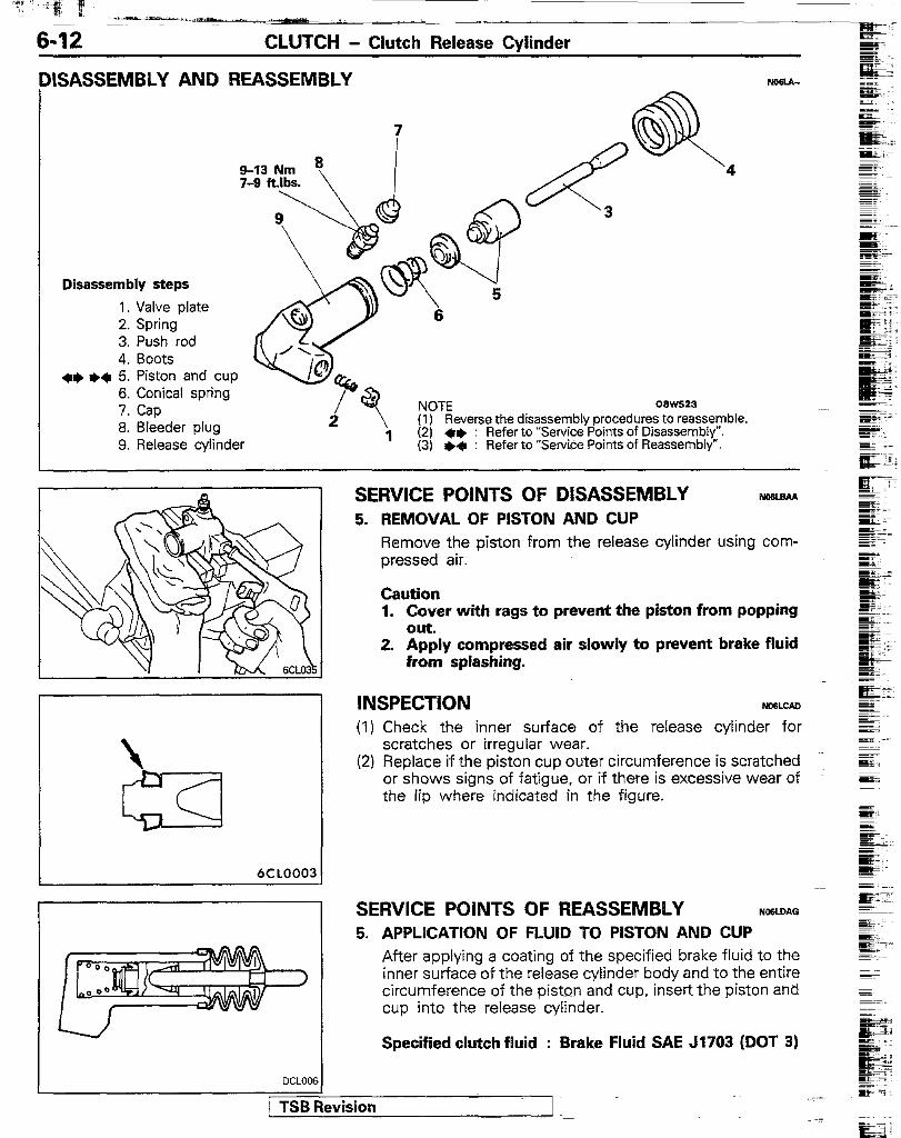
GASSEMBLY AND REASSEMBLY
Disassembly steps
1. Valve plate 2. Spring’ 3. Push rod 4. Boots
+I) *q 5. Piston and cup 6. Conical spring 7. Cap 8. Bleeder plug 9. Release cylinder
NOTE 08W523 (1) Reverse the disassembly procedures to reassemble. (2) a+ : Refer to “Service Points of Disassembly”. (3) +4 : Refer to “Service Points of Reassembly”.
SERVICE POINTS OF DISASSEMBLY WsLaAA 5. REMOVAL OF PlSTON AND CUP
Remove the piston from the release cylinder using com- pressed air.
Caution 1. Cover with rags to prevent the piston from popping
Out. 2. Apply compressed air slowly to prevent brake fluid
from splashing.
INSPECTION (I) Check the inner surface of the release cylinder for
scratches or irregular wear. (2) Replace if the piston cup outer circumference is scratched
or shows signs of fatigue, or if there is excessive wear of the lip where indicated in the figure.
SERVICE POINTS OF REASSEMBLY NOSLOAO 5. APPLICATION OF FLUID TO PISTON AND CUP
After applying a coating of the specified brake fluid to the inner surface of the release cylinder body and to the entire circumference of the piston and cup, insert the piston and cup into the release cylinder.
Specified clutch fluid : Brake Fluid SAE J1703 (DOT 3)
CLUTCH - Clutch Disc 6-13
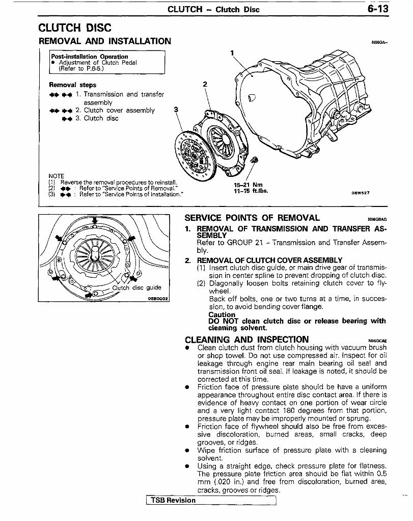
CLUTCH DISC REMOVAL AND INSTALLATION
71
Removal steps 41) ++ 1. Transmission and transfer
assembly 41) l + 2. Clutch cover assembly
H 3. Clutch disc
NOTE (1 I (21
Reverse the removal procedures to reinstall. l * : Refer to “Service Points of Removal.”
(3) +* : Refer to “Service Points of Installation.” 15-21 Nm I 1-15 klbs.
SERVICE POINTS OF REMOVAL 1. ;EX;“L OF TRANSMISSION AND TRANSFER AS-
Refer to GROUP 21 - Transmission and Transfer Assem- bly.
2. REMOVAL OF CLUTCH COVER ASSEMBLY (1) insert clutch disc guide, or main drive gear of transmis-
sion in center spline to prevent dropping of clutch disc. (2) Diagonally loosen bolts retaining clutch cover to fly-
wheel. Back off bolts, one or two turns at a time, in succes- sion, to avoid bending cover flange. Caution DO NOT clean clutch disc or release bearing with cleaning solvent.
CLEANING AND INSPECTION NWGCAE l Clean clutch dust from clutch housing with vacuum brush
or shop towel. Do not use compressed air. Inspect for oil leakage through engine rear main bearing oil seal and transmission front oil seal. If leakage is noted, it should be corrected at this time.
l Friction face of pressure plate should be have a uniform appearance throughout entire disc contact area. If there is evidence of heavy contact on one portion of wear circle and a very light contact 180 degrees from that portion, pressure plate may be improperly mounted or sprung.
l Friction face of flywheel should also be free from exces- sive discoloration, burned areas, small cracks, deep grooves, or ridges.
l Wipe friction surface of pressure plate with a cleaning solvent.
l Using a straight edge, check pressure plate for flatness. The pressure plate friction area should be flat within 0.5 mm (.020 in.) and free from discoloration, burned area, cracks, grooves or ridges.
/ TSB Revision
6-14 CLUTCH - Clutch Disc
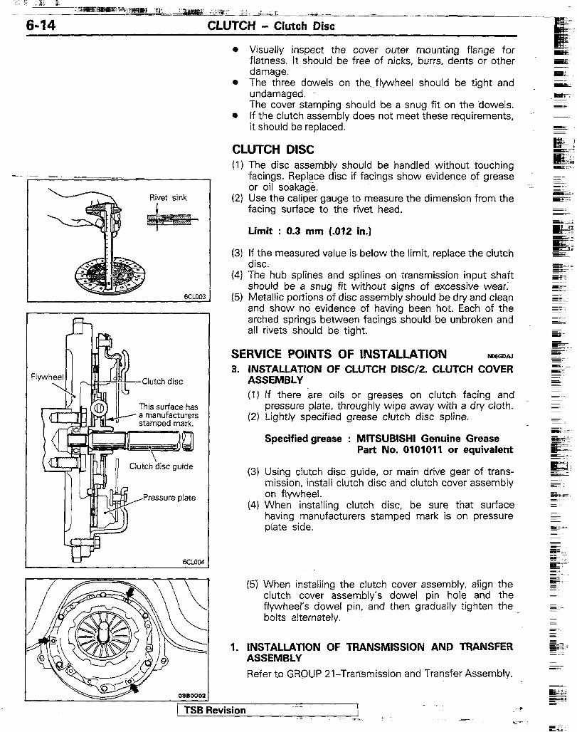
Clutch disc
This surface has
l Visually inspect the cover outef mounting flange for flatness. It should be free-of nicks, burrs, dents or other damage.
* The three dowels on the. flywheel should be tight and undamaged. The cover stamping should be a snug fit on the dowels.
e if the clutch assembly does not meet these requirements, it should be replaced.
CLUTCH DISC (1) The disc assembly should be handled without touching
facings. Replace disc if facings show evidence of grease or oil soakatie.
(2) Use the caliper gauge to measure the dimension from the facing surface to the rivet head.
Limit : 0.3 mm (.012 in.)
(3) ii;: measured value is below the limit, replace the clutch
(4) The’hub splines and splines on transmission input shaft should be a snug fit without signs of excessive wear:
(5) Metallic portions of disc assembly should be dry and clean and show no evidence of having been hot. Each of the arched springs between facings should be unbroken and all rivets should be tight.
SERWCE POINTS OF INSTALLATION NOGGDAJ
3. INSTALLATION OF CLUTCH DISC/2. CLUTCH COVER ASSEMBLY (I) If there are oils or greases on clutch facing and
pressure plate, throughly wipe away with a dry cloth. (2) Lightly specified grease clutch disc spline.
Specified grease : MITSUBISHI Gemtine Grease Part No. 0101011 or equivalent
(3) Using clutch disc guide, or main drive gear of trans- mission, install clutch disc and clutch cover assembly on flywheel.
(4) When installing clutch disc, be sure that surface having manufacturers stamped mark is on pressure plate side.
1 TSB Revision 1 1
(5) When installing the clutch cover assembly, align the clutch cover assembly’s dowel pin hole and the flywheel’s dowel pin, and then gradually tighten the bolts alternately.
1. INSTALLATION OF TRANSMISSION AND TRANSFER ASSEMBLY
Refer to GROUP 21-Transmission and Transfer Assembly.
P
---
CLUTCH - Clutch Release Fork <2.6LEngine>
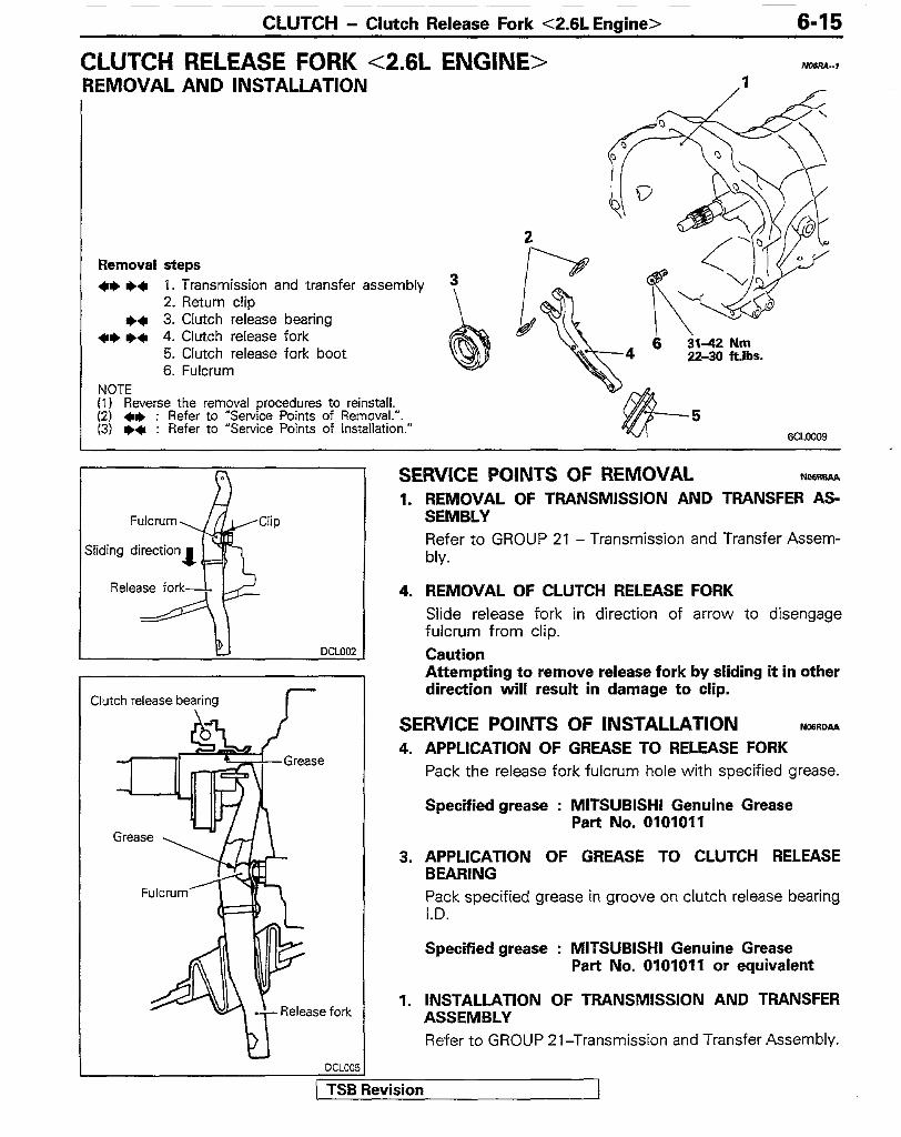
CLUTCH RELEASE FORK <2.6L ENGINE>
6-15
NnsR4--I REMOVAL AND INSTALLATION 1
Removal steps ++ WI 1. Transmission and transfer assembly
2. Return clip ++ 3. Clutch release bearing
++ I)* 4. Clutch release fork 5. Clutch release fork boot 6. Fulcrum
NOTE (1) Reverse the removal procedures to reinstall. (2) ** : Refer to “Service Points of Removal.“. (3) l * : Refer to “Service Points of Installation.”
DCLOOZ
Clutch release bearing I-
fork
SERVICE POINTS OF REMOVAL NOSRBAA 1. REMOVAL OF TRANSMISSION AND TRANSFER AS-
SEMBLY Refer to GROUP 21 - Transmission and Transfer Assem- bly.
4. REMOVAL OF CLUTCH RELEASE FORK Slide release fork in direction of arrow to disengage fulcrum from clip. Caution Attempting to remove release fork by sliding it in other direction will result in damage to clip.
SERVlCE POINTS OF INSTALLATION NcmDAA 4. APPLICATION OF GREASE TO RELEASE FORK
Pack the release fork fulcrum hole with specified grease.
Specified grease : MITSUBISHI Genuine Grease Part No. 0101011
3. APPLICATION OF GREASE TO CLUTCH RELEASE BEARING Pack specified grease in groove on clutch release bearing I.D.
Specified grease : MITSUBISHI Genuine Grease Part No. 0101011 or equivalent
1. INSTALLATiON OF TRANSMISSION AND TRANSFER ASSEMBLY Refer to GROUP 21-Transmission and Transfer Assembly.
6-16 CLUTCH - Clutch Release Fork <3.OLEngine>
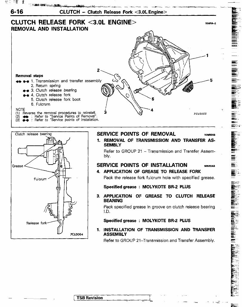
CLUTCH RELEASE FORK <3.OL ENGINE> REMOVAL AND INSTALLATION
Removal steps 2
+e l + 1. Transmission and transfer assembl 2. Return spring
+* 3. Clutch release bearing +* 4. Clutch release fork
5. Clutch release fork boot 6. Fulcrum
NOTE (1) Reverse the removal procedures to reinstall. (2) *I) : Refer to “Service Points of Removal”. (3) l + : Refer to “Service points of Installation.
Fulcrum
Release fork’
Y
Clutch release bearing SERVICE POINTS OF REMOVAL No6aaAe 1. REMOVAL OF TRANSMISSION AND TRANSFER AS-
SEMBLY Refer to GROUP 21 - Transmission and Transfer Assem- bly.
SERWCE POINTS OF INSTALLATION NM)mAa 4. APPLICATION OF GREASE TO RELEASE FORK
Pack the release fork fulcrum hole with specified grease.
Specified grease : MOLYKOTE BR-2 PLUS
3. APPLICATION OF GREASE TO CLUTCH RELEASE BEARING Pack specified grease in groove on clutch release bearing I.D.
Specified grease : MOLYKOTE BR-2 PLUS
1. INSTALLATION OF TRANSMISSION AND TRANSFER ASSEMBLY Refer to GROUP 21-Transmission and Transfer Assembly.
( TSB Revision