1300 series a2 - fisher scientific.pdfthermo scientific 1300 series a2 1-3 section 1 description...
TRANSCRIPT

1300 Series A2Class II, Type A2 Biological Safety CabinetOperating Manual 7011355 Rev. 20

Thermo ScientificThermo Scientific
MANUAL NUMBER 7011355
20 26097 9/13/10 Added lockwashers to adjustable height stand - pg 3-2 ccs
19 26153, 26074/HD-1660 2/15/10 Added models and specs for 8” opening, 2nd receptacle to 4’ units ccs
Preface
1300 Series A2 i
This manual covers the models shown below:
Dear User,
Congratulations on your purchase of a Thermo Scientific 1300 Series Class II, Type A2 biologicalsafety cabinet! Your 1300 Series A2 biological safety cabinet has been tested and certified inaccordance to NSF/ANSI 49, and is designed to protect the user, the environment, and yourresearch from harmful substances and cross-contamination. This user’s manual provides instructionson how to use the 1300 Series A2 most effectively and safely.
Containment * Comfort * Convenience™
The 1300 Series A2 offers a unique range of product features that will enhance your safety andimprove overall operating efficiency. Should you have any questions on using this product or needfurther explanation of any of it’s features, please contact Technical Services (Page iv), or your localdistributor.
Stainless Steel Interior Painted Interior Size Voltage
10 inch opening 8 inch opening 10 inch opening 8 inch opening
1354 4 ft 230V, China
1345 1305 1355 1325 4 ft 120V
1346 1306 1356 1326 4 ft 230V
1347 1307 1357 1327 6 ft 120V
1348 1308 1358 1328 6 ft 230V
1359 6 ft 230V, China
1384* 4 ft 230V, China
1375 1335 1385* 1395 4 ft 120V
1376 1336 1386* 1396 4 ft 230V
1377 1337 1387* 1397 6 ft 120V
1378 1338 1388* 1398 6 ft 230V
1389* 6 ft 230V China
* Includes cabinet, adjustable height stand, UV light and armrest.

Thermo Scientificii 1300 Series A2
Preface
Important Read this instruction manual. Failure to read, understand and follow the instructions in this manualmay result in damage to the unit, injury to operating personnel, and poor equipment performance. s
Caution All internal adjustments and maintenance must be performed by qualified service personnel. s
Material in this manual is for information purposes only. The contents and the product it describes are subject tochange without notice. Thermo Scientific makes no representations or warranties with respect to this manual. Inno event shall Thermo Scientific be held liable for any damages, direct or incidental, arising out of or related tothe use of this manual.
©2007 Thermo Scientific. All rights reserved.
Thermo Scientific 1300 Series A2 iiiThermo Scientific
Preface
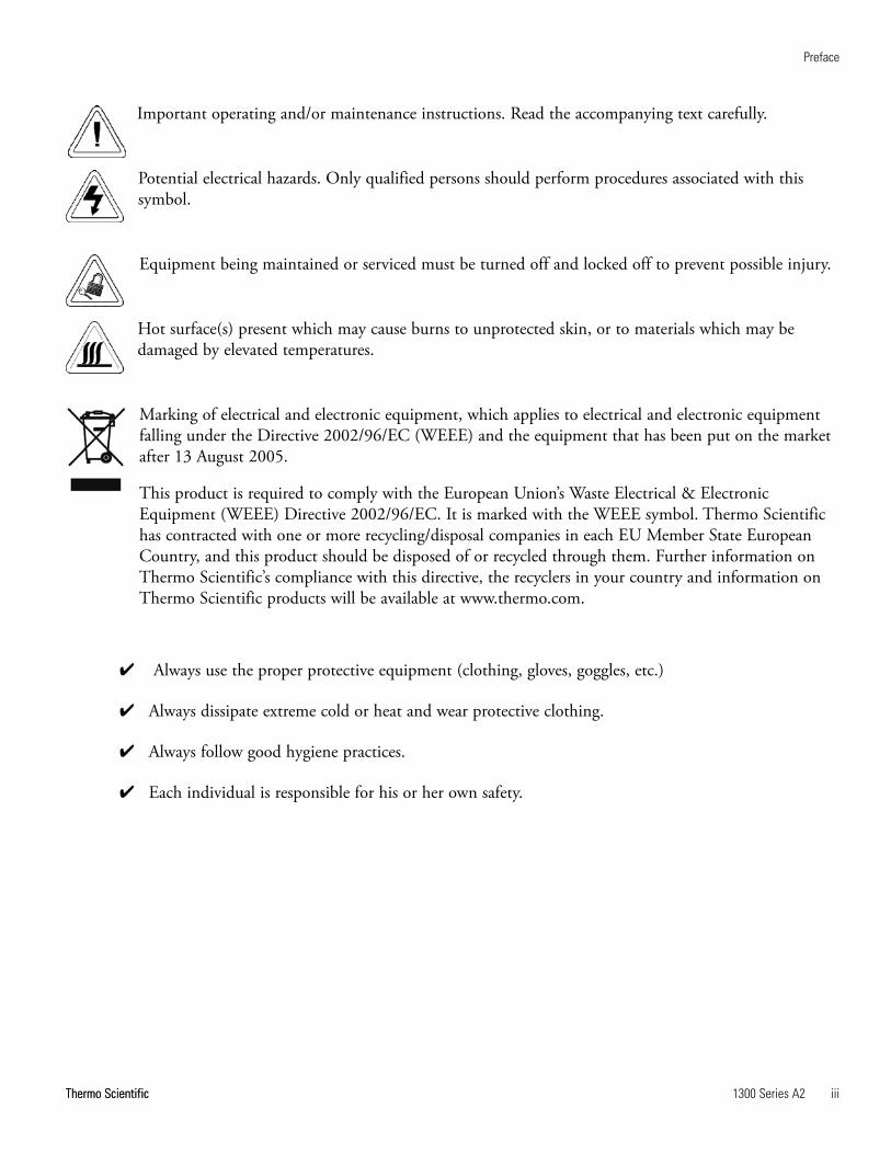
Important operating and/or maintenance instructions. Read the accompanying text carefully.
Potential electrical hazards. Only qualified persons should perform procedures associated with thissymbol.
Equipment being maintained or serviced must be turned off and locked off to prevent possible injury.
Hot surface(s) present which may cause burns to unprotected skin, or to materials which may bedamaged by elevated temperatures.
Marking of electrical and electronic equipment, which applies to electrical and electronic equipmentfalling under the Directive 2002/96/EC (WEEE) and the equipment that has been put on the marketafter 13 August 2005.
This product is required to comply with the European Union’s Waste Electrical & ElectronicEquipment (WEEE) Directive 2002/96/EC. It is marked with the WEEE symbol. Thermo Scientifichas contracted with one or more recycling/disposal companies in each EU Member State EuropeanCountry, and this product should be disposed of or recycled through them. Further information onThermo Scientific’s compliance with this directive, the recyclers in your country and information onThermo Scientific products will be available at www.thermo.com.
4 Always use the proper protective equipment (clothing, gloves, goggles, etc.)
4 Always dissipate extreme cold or heat and wear protective clothing.
4 Always follow good hygiene practices.
4 Each individual is responsible for his or her own safety.

Thermo Scientificiv 1300 Series A2 Thermo Scientific
Preface
Do You Need Information or Assistance on
Thermo Scientific Products?
If you do, please contact us 8:00 a.m. to 6:00 p.m. (Eastern Time) at:
1-740-373-4763 Direct
1-800-438-4851 Toll Free, U.S. and Canada
1-877-213-8051 FAX
http://www.thermofisher.com Internet Worldwide Web Home Page
Service E-Mail Address
Thermo Fisher Scientific
401 Millcreek Road, Box 649
Marietta, OH 45750
Our staff can provide information on pricing and give you quotations. We can
take your order and provide delivery information on major equipment items or make
arrangements to have your local sales representative contact you. Our products are listed on the
Internet and we can be contacted through our Internet home page.
Our staff can supply technical information about proper setup, operation or
troubleshooting of your equipment. We can fill your needs for spare or replacement parts or
provide you with on-site service. We can also provide you with a quotation on our Extended
Warranty for your Thermo Scientific products.
Whatever Thermo Scientific products you need or use, we will be happy to discuss your
applications. If you are experiencing technical problems, working together, we will help you
locate the problem and, chances are, correct it yourself...over the telephone without a service
call.
When more extensive service is necessary, we will assist you with direct factory trained
technicians or a qualified service organization for on-the-spot repair. If your service need is
covered by the warranty, we will arrange for the unit to be repaired at our expense and to your
satisfaction.
Regardless of your needs, our professional telephone technicians are available to assist you
Monday through Friday from 8:00 a.m. to 6:00 p.m. Eastern Time. Please contact us by
telephone or fax. If you wish to write, our mailing address is:
International customers, please contact your local Thermo Scientific distributor.
Sales Support
Service Support
1300 Series A2 vThermo Scientific
Table of Contents
Description . . . . . . . . . . . . . . . . . . . . . . . . . . . . . . . . . . . . . . . . . . . . . . . . . .1-1Safety Systems . . . . . . . . . . . . . . . . . . . . . . . . . . . . . . . . . . . . . . . . . .1-2HEPA Filters . . . . . . . . . . . . . . . . . . . . . . . . . . . . . . . . . . . . . . . . . . .1-4Paper Catch Grids . . . . . . . . . . . . . . . . . . . . . . . . . . . . . . . . . . . . . . .1-4Control Panel . . . . . . . . . . . . . . . . . . . . . . . . . . . . . . . . . . . . . . . . . . .1-5Use of the Window . . . . . . . . . . . . . . . . . . . . . . . . . . . . . . . . . . . . . .1-6Unit Interface . . . . . . . . . . . . . . . . . . . . . . . . . . . . . . . . . . . . . . . . . . .1-7Chamber Lighting . . . . . . . . . . . . . . . . . . . . . . . . . . . . . . . . . . . . . . .1-8UV Lights . . . . . . . . . . . . . . . . . . . . . . . . . . . . . . . . . . . . . . . . . . . . .1-9Work Area . . . . . . . . . . . . . . . . . . . . . . . . . . . . . . . . . . . . . . . . . . . . .1-9
Installation . . . . . . . . . . . . . . . . . . . . . . . . . . . . . . . . . . . . . . . . . . . . . . . . . .2-1Optional Exhaust Transition . . . . . . . . . . . . . . . . . . . . . . . . . . . . . . .2-2
Exhaust System Accessories . . . . . . . . . . . . . . . . . . . . . . . . . . . . . . .2-2Moving the Unit . . . . . . . . . . . . . . . . . . . . . . . . . . . . . . . . . . . . . . . .2-4Service Valve Connections . . . . . . . . . . . . . . . . . . . . . . . . . . . . . . . . .2-5Universal Piping Connections . . . . . . . . . . . . . . . . . . . . . . . . . . . . . .2-7
Start-Up . . . . . . . . . . . . . . . . . . . . . . . . . . . . . . . . . . . . . . . . . . . . . . . . . . . . .3-1Unit w/wo Stand . . . . . . . . . . . . . . . . . . . . . . . . . . . . . . . . . . . . . . . .3-1Unlock Counterweight . . . . . . . . . . . . . . . . . . . . . . . . . . . . . . . . . . . .3-3Power Connection . . . . . . . . . . . . . . . . . . . . . . . . . . . . . . . . . . . . . . .3-4Installation Tests . . . . . . . . . . . . . . . . . . . . . . . . . . . . . . . . . . . . . . . . .3-5Locating a Certifier . . . . . . . . . . . . . . . . . . . . . . . . . . . . . . . . . . . . . .3-6
Operation . . . . . . . . . . . . . . . . . . . . . . . . . . . . . . . . . . . . . . . . . . . . . . . . . . . .4-1Calibration Procedure . . . . . . . . . . . . . . . . . . . . . . . . . . . . . . . . . . . .4-2Unit Start-Up . . . . . . . . . . . . . . . . . . . . . . . . . . . . . . . . . . . . . . . . . . .4-3Operating Modes . . . . . . . . . . . . . . . . . . . . . . . . . . . . . . . . . . . . . . . .4-3Loading the Chamber . . . . . . . . . . . . . . . . . . . . . . . . . . . . . . . . . . . .4-5Error Messages . . . . . . . . . . . . . . . . . . . . . . . . . . . . . . . . . . . . . . . . . .4-5Working Recommendations . . . . . . . . . . . . . . . . . . . . . . . . . . . . . . . .4-6Procedure Interrupt . . . . . . . . . . . . . . . . . . . . . . . . . . . . . . . . . . . . . .4-7Unit Shut-down . . . . . . . . . . . . . . . . . . . . . . . . . . . . . . . . . . . . . . . . .4-8Unit Disposal . . . . . . . . . . . . . . . . . . . . . . . . . . . . . . . . . . . . . . . . . . .4-8
Section 1
Section 2
Section 3
Section 4
vi 1300 Series A2 Thermo Scientific
Cleaning / Decontamination . . . . . . . . . . . . . . . . . . . . . . . . . . . . . . . . . . .5-1Cleaning and Care of Stainless Steel . . . . . . . . . . . . . . . . . . . . . . . . . .5-1Cleaning and Care of Coated Surfaces . . . . . . . . . . . . . . . . . . . . . . . .5-2Disinfection . . . . . . . . . . . . . . . . . . . . . . . . . . . . . . . . . . . . . . . . . . . .5-3Rinsing . . . . . . . . . . . . . . . . . . . . . . . . . . . . . . . . . . . . . . . . . . . . . . . .5-3UV Disinfection after Disinfection . . . . . . . . . . . . . . . . . . . . . . . . . .5-4Disinfection with Formaldehyde . . . . . . . . . . . . . . . . . . . . . . . . . . . .5-4Clean Exterior Surfaces . . . . . . . . . . . . . . . . . . . . . . . . . . . . . . . . . . .5-4Clean Window . . . . . . . . . . . . . . . . . . . . . . . . . . . . . . . . . . . . . . . . . .5-4Clean the Drain Pan . . . . . . . . . . . . . . . . . . . . . . . . . . . . . . . . . . . . .5-5Clean the Paper Catch Grid . . . . . . . . . . . . . . . . . . . . . . . . . . . . . . . .5-5
Maintenance . . . . . . . . . . . . . . . . . . . . . . . . . . . . . . . . . . . . . . . . . . . . . . . .6-1Service . . . . . . . . . . . . . . . . . . . . . . . . . . . . . . . . . . . . . . . . . . . . . . . .6-2
Sample Chamber Lights . . . . . . . . . . . . . . . . . . . . . . . . . . . . . . . . .6-2Optional UV Lights . . . . . . . . . . . . . . . . . . . . . . . . . . . . . . . . . . . .6-2
Replacements and Repairs . . . . . . . . . . . . . . . . . . . . . . . . . . . . . . . . .6-3Unit Disposal . . . . . . . . . . . . . . . . . . . . . . . . . . . . . . . . . . . . . . . . . . .6-3
Specifications . . . . . . . . . . . . . . . . . . . . . . . . . . . . . . . . . . . . . . . . . . . . . . .7-1
Certification Testing . . . . . . . . . . . . . . . . . . . . . . . . . . . . . . . . . . . . . . . . . .8-1
Data Log/Warranty . . . . . . . . . . . . . . . . . . . . . . . . . . . . . . . . . . . . . . . . . . .9-1
Table of Contents
Section 5
Section 6
Section 8
Section 7
Section 9
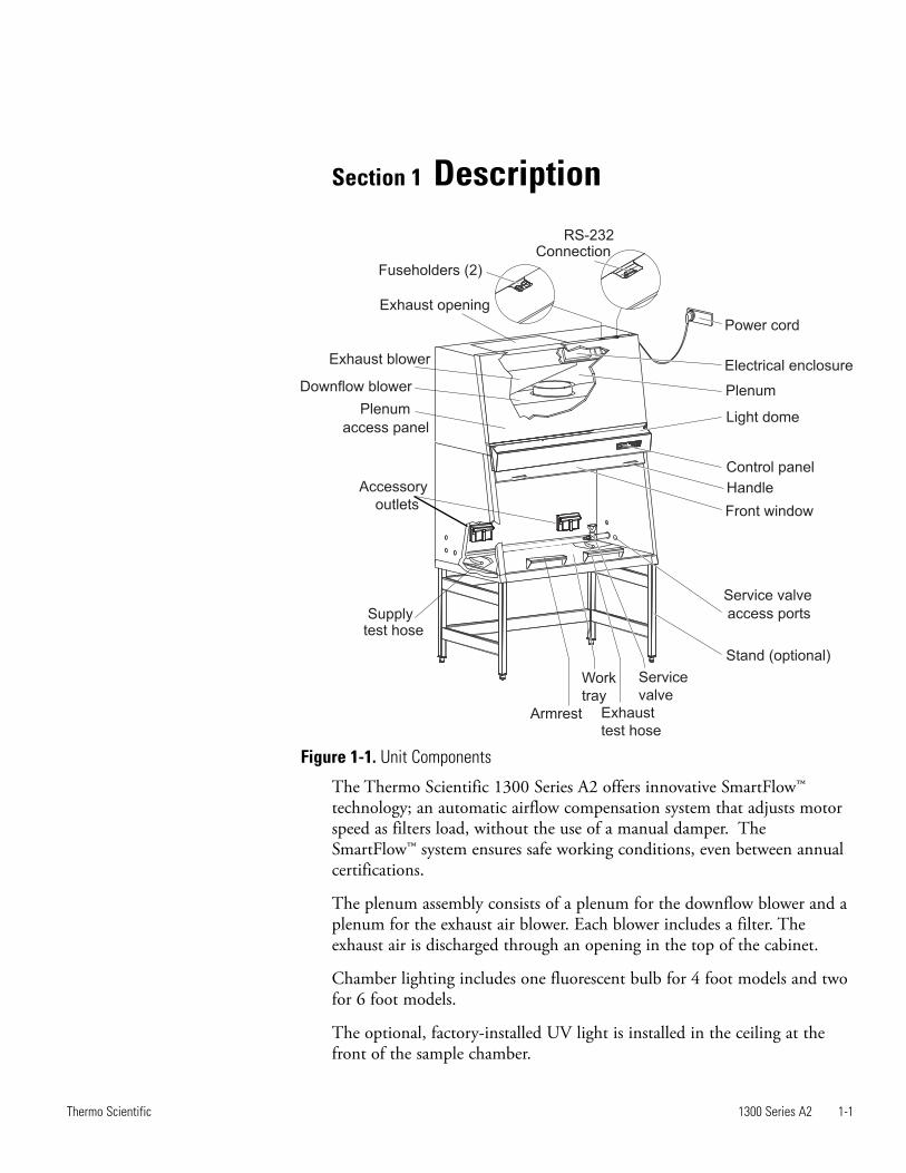
1300 Series A2 1-1Thermo Scientific
Section 1 Description
The Thermo Scientific 1300 Series A2 offers innovative SmartFlow™technology; an automatic airflow compensation system that adjusts motorspeed as filters load, without the use of a manual damper. TheSmartFlow™ system ensures safe working conditions, even between annualcertifications.
The plenum assembly consists of a plenum for the downflow blower and aplenum for the exhaust air blower. Each blower includes a filter. Theexhaust air is discharged through an opening in the top of the cabinet.
Chamber lighting includes one fluorescent bulb for 4 foot models and twofor 6 foot models.
The optional, factory-installed UV light is installed in the ceiling at thefront of the sample chamber.
Figure 1-1. Unit Components
Plenum
Power cord
Electrical enclosure
Light dome
Control panel
Handle
Front window
Service valve
access ports
Stand (optional)
Service
valve
Exhaust
test hose
Work
tray
Armrest
Supplytest hose
Accessory
outlets
Plenum
access panel
Downflow blower
Exhaust blower
RS-232Connection
Fuseholders (2)
Exhaust opening

1-2 1300 Series A2 Thermo Scientific
Section 1Description
Safety Systems
Three service valve access ports are located on each side panel. Wheninstalling service valves, remove the center of the port plugs at theperforations.
The optional stand is may be ordered in two configurations; a manuallyadjustable from 30” to 38” working height, and a fixed 34” workingheight with attached casters.
A stainless steel one-piece work surface is standard. Optional armrestsensure a comfortable working position for the user and minimizeblockage of airflow at the front grille.
Internal outlets, provided as the power source for accessories, are providedstandard in the following configuration:
1305, 1307, 1325, 1327, 1335, 1337, 1345, 1347, 1355, 1357, 1375,1377, 1385, 1387, 1395, 1397: two duplex right and left side1306, 1308, 1326, 1328, 1336, 1338, 1346, 1348, 1358, 1359, 1376,1378, 1388, 1389, 1396, 1398: two single right and left side
Test hoses (aerosol challenge ports) are located under the work tray. Thesupply plenum hose is located on the left and the exhaust plenum hose onthe right.
Note Do not remove the caps of the two test hoses to check for supplyand exhaust airflow. s
Negative pressure air systemA negative pressure air system combines with HEPA filters in the supplyand exhaust airflow for personal and product protection.
Personnel protectionInflow air along the entire working opening at a constant high velocityprevents leakage from the work opening of the chamber.Exterior air pressure being higher than the internal air pressure createsnegative pressure, ensuring containment in case of cabinet leakage.
Product protectionSteady airflow within the air system ensures constant downflow, allow-ing the HEPA filters to remove contaminants so that the samples arealways surrounded by ultra-pure air. Harmful particles are not carriedover the sample chamber (protection from cross-contamination).
HEPA filtersThe downflow air within the chamber and the exhaust air are cleanedby HEPA filters.

1300 Series A2 1-3Thermo Scientific
Section 1Description
Safety lockoutTo protect from UV radiation, the optional UV light will not turn on ifthe front window is open. While the UV light is on, the front window isclosed and locked. The closed window blocks out the UV rays.
Digital Airflow Verification (DAVe)Independent monitoring of inflow and downflow air velocities guaran-tees that product and personal protection remain uncompromised.Airflow monitoring determines the velocity of the airflow in the samplechamber as well as the inflow velocity of air through the exhaust open-ing. As soon as airflow velocities rise above or fall below a specified safetyvalue, an audible and a visual alarm is activated.
Window position monitoringThe position sensors detect the size of the front window opening andindicate whether the window is open to the specified work position,closed (energy saving) or in an unsafe intermediate position.
Thermo Performance FactorThe Thermo Performance Factor (PER) is a value that indicates the safe-ty status of the cabinet. This value is calculated from data determined byHEPA filter loading, airflow status and values captured during certifica-tion. This data is entered into a parameter list of the control softwareand interconnected. The result is indicated on the display by LEDs.On certification by qualified personnel with a new HEPA filter, the per-formance factor of the unit is indicated by green-green LEDs. As theunit ages with use, the colors change. Red-red is unacceptable and theunit should not be used. Any questions as to the safety of the unitshould be resolved before use.
Safety Systems(continued)
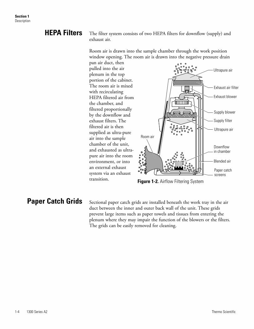
The filter system consists of two HEPA filters for downflow (supply) andexhaust air.
Room air is drawn into the sample chamber through the work positionwindow opening. The room air is drawn into the negative pressure drainpan air duct, thenpulled into the airplenum in the topportion of the cabinet.The room air is mixedwith recirculatingHEPA filtered air fromthe chamber, andfiltered proportionallyby the downflow andexhaust filters. Thefiltered air is thensupplied as ultra-pureair into the samplechamber of the unit,and exhausted as ultra-pure air into the roomenvironment, or intoan external exhaustsystem via an exhausttransition.
Sectional paper catch grids are installed beneath the work tray in the airduct between the inner and outer back wall of the unit. These gridsprevent large items such as paper towels and tissues from entering theplenum where they may impair the function of the blowers or the filters.The grids can be easily removed for cleaning.
1-4 1300 Series A2 Thermo Scientific
Section 1Description
HEPA Filters
Ultrapure air
Exhaust air filter
Exhaust blower
Supply blower
Supply filter
Ultrapure air
Downflowin chamber
Blended air
Paper catchscreens
Room air
Figure 1-2. Airflow Filtering System
Paper Catch Grids

1300 Series A2 1-5Thermo Scientific
Section 1Description
The control panel is located on the front of the cabinet and consists ofkeys, status indicators and a numerical display.
The display with its 5-digit panel shows the following information,regardless of the activated operating function:
• operating hours of the device• downflow and inflow air velocities• remaining time of the UV disinfection routine
The keys turn functions on or off.
Status indicators show:
• window work position• airflow• reduced blower speed• Thermo Performance Factor
Control Panel
Display Keys
Status Indicators
Figure 1-3. Control Panel

The sample chamber is accessible through various positions of the frontwindow. The working position of the window is a 8 or 10 inch opening,+0.25”, -0.75” (depending on model - check data label and first page ofthis manual). For loading the chamber, the window opens fully. Fordecontamination and energy saving, enter into Night-Set-Back mode byclosing the window. When the window is closed, the blower speed isreduced, minimizing energy consumption and noise emittance withoutcompromising particulate containment inside the work chamber.
Note The working and loading window positions are indicated on the userinterface, as controlled by micro switches and displayed by statusindicators on the control panel. s
Use of the Window
1-6 1300 Series A2 Thermo Scientific
Section 1Description
Window
Window
Pillar dresspanel
Opening height
for cleaning window
Pillar dresspanel
Closed position
Workposition
Max opening forloading samples
1300 SERIES A2
1300 SERIES A2
Figure 1-4. Window Openings

To place the window at the work position, move it to the area of the top‘dimple’ (Figure 1-5) and watch for the GREEN sash position heightindicator to illuminate (Figure1-6). If the window is moved from the thework position, the sash height indicator will turn RED.
To place the window in the closed or reduced mode position, move it tothe area of the lower ‘dimple’ (Figure 1-7) and watch for the BLUEreduced mode indicator to illuminate (Figure1-8). If the window is notpositioned correctly, or is moved from the closed position, the BLUEindicator will be extinguished. When the BLUE reduced mode indicatoris not illuminated, the unit will not operate in reduced mode, and theoptional UV light will not function.
1300 Series A2 1-7Thermo Scientific
Section 1Description
Use of the Window(continued)
Figure 1-5. Work Position Figure 1-6. Lighted Green LED
Figure 1-7. Fully Closed Position (UV, if applicable) Figure 1-8. Lighted Blue LED
dimple
dimple
1-8 1300 Series A2 Thermo Scientific
Section 1Description
To reduce the risk of sample cross-contamination, our patentedSmartClean™ window design easily lowers for thorough cleaning of thewindow sash interior. This unique design protects the operator bymaintaining a clean air curtain even when the window is lowered.
1. Lower the window to the SmartClean position (below the workposition). An alarm will sound and can be muted during the cleaningprocess.
2. Upon completion of the cleaning/service work, push the front windowback in place.
Note The SmartClean position can be also used for replacing the samplechamber light bulbs. s
Caution If the front window jams or is sluggish to move, do not use force!Contact Technical Services immediately. Do not attempt to repair thisproblem. s
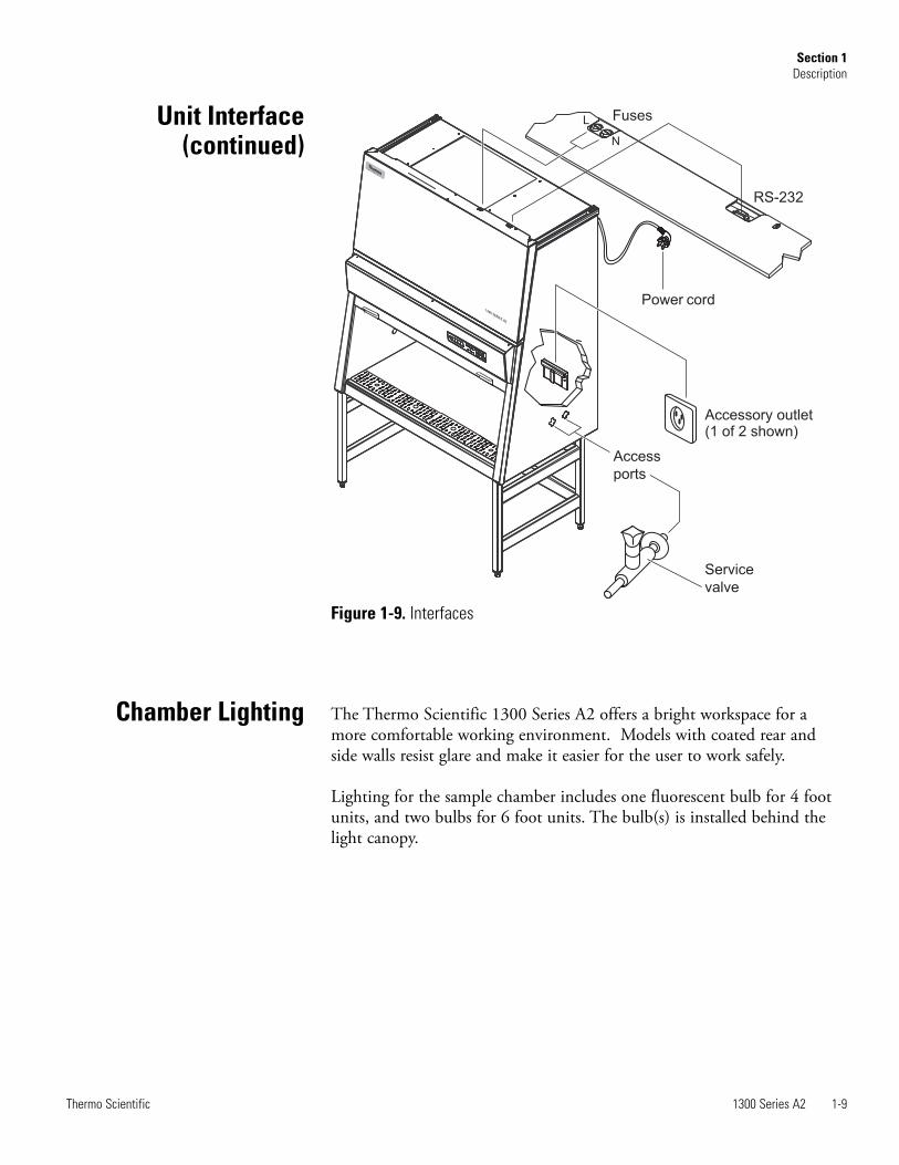
The standard unit includes accessory outlets, service valve access ports, anRS-232 connection and a remote alarm connection.
The power cord to be connected to the power source is located on theupper back of the cabinet.
The accessory outlets (max 5A) are located on the interior chamber backwall.
On top of the cabinet are the two fuseholders for the 5A circuit breakerfuses and an RS-232 connection.
Service valve access ports are located on each side of the cabinet. To usethese ports, remove the center perforation. Service valves are available asoptional accessories.
The remote alarm accessory can be used for external exhaust air systemcontrols, or a failure reporting system.
Warning If a gas burner is to be operated in the sample chamber, anappropriate shut-off valve for the gas supply must be installed. Use onlylaboratory safe burners in the sample chamber. s
Use of the Window(continued)
Unit Interface
1300 Series A2 1-9Thermo Scientific
Section 1Description
The Thermo Scientific 1300 Series A2 offers a bright workspace for amore comfortable working environment. Models with coated rear andside walls resist glare and make it easier for the user to work safely.
Lighting for the sample chamber includes one fluorescent bulb for 4 footunits, and two bulbs for 6 foot units. The bulb(s) is installed behind thelight canopy.
Service
valve
Access
ports
Power cord
RS-232
Fuses
N
L
Accessory outlet(1 of 2 shown)
Figure 1-9. Interfaces
Chamber Lighting
Unit Interface(continued)
1-10 1300 Series A2 Thermo Scientific
Section 1Description
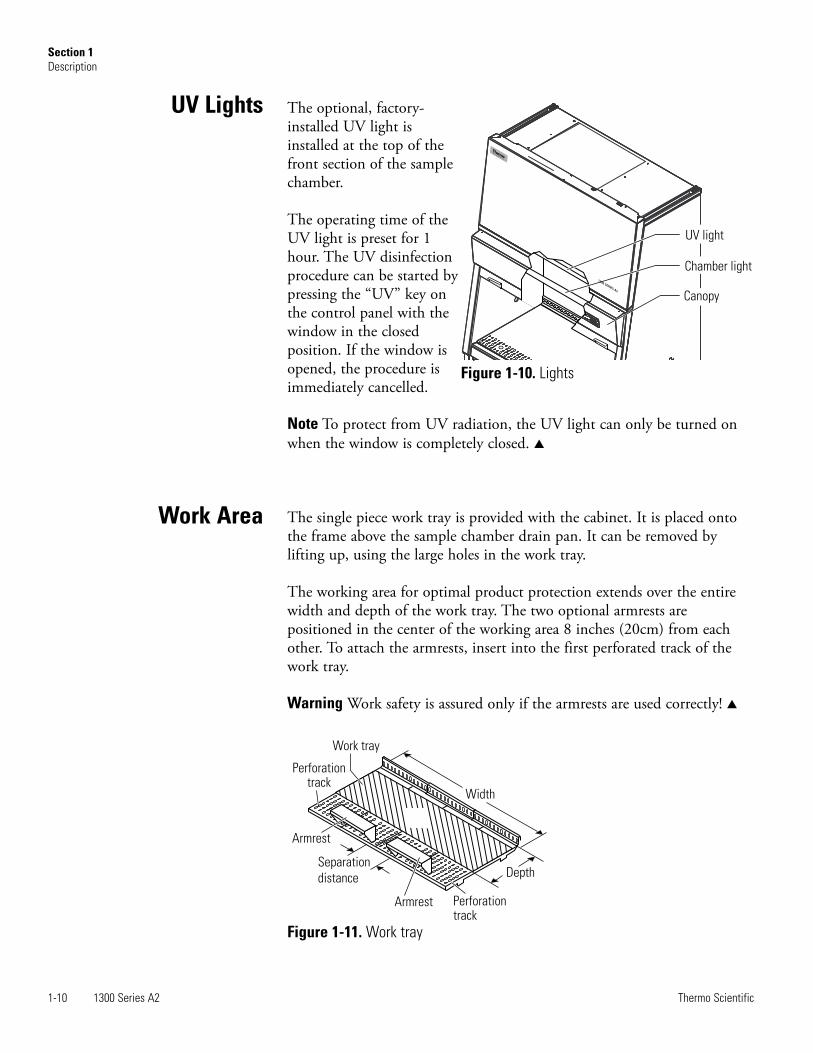
The optional, factory-installed UV light isinstalled at the top of thefront section of the samplechamber.
The operating time of theUV light is preset for 1hour. The UV disinfectionprocedure can be started bypressing the “UV” key onthe control panel with thewindow in the closedposition. If the window isopened, the procedure isimmediately cancelled.
Note To protect from UV radiation, the UV light can only be turned onwhen the window is completely closed. s
The single piece work tray is provided with the cabinet. It is placed ontothe frame above the sample chamber drain pan. It can be removed bylifting up, using the large holes in the work tray.
The working area for optimal product protection extends over the entirewidth and depth of the work tray. The two optional armrests arepositioned in the center of the working area 8 inches (20cm) from eachother. To attach the armrests, insert into the first perforated track of thework tray.
Warning Work safety is assured only if the armrests are used correctly! s
Work Area
UV Lights
UV light
Chamber light
Canopy
Figure 1-10. Lights
Width
Depth
Perforationtrack
Armrest
Armrest
Separation
distance
Perforationtrack
Work tray
Figure 1-11. Work tray
1300 Series A2 2-1Thermo Scientific
Section 2 Installation
The operational safety and proper function of the unit depend on thelocation where it is to be operated. The cabinet should be operated only inthe ambient conditions listed below.
• Up to 6562 ft. (2000m) above sea level.
• Power outlet accessible to authorized personnel only. Ideally, the outletshould be installed above the biological safety cabinet. The power cordis the mains disconnect.
• Location capable of supporting the weight of the device and non-flammable.
• If the factory-approved stand is not purchased, the holding device mustbe rated for twice the cabinet weight.
• Adequate room height. For devices that are not connected to anexhaust system, the distance between the exhaust air opening at thedevice and the room ceiling must be at least 8 inches (200mm).
• Equipped with an appropriate ventilation system.
• Room temperature between 10°C and 40°C (50°F and 104°F).
• Relative humidity must not exceed 80%, up to 31°C and decreasinglinearly to 50% at 40°C.
• For indoor use only.
Room ventilation should preferably be a ventilation system that complieswith the national requirements for the application.
The inlet air and exhaust air openings of the room ventilation must belocated so that drafts do not impair the function of the biological safetycabinet air system.
When positioning the cabinet, make sure the counterweight on the back ofthe unit can move freely. The minimal distance to the wall or adjacentobjects should be 3 inches (7.6cm).

The part numbers for the optional thimble exhaust connection are1911316 for four foot, and 1911317 for six foot units.
The test conditions according to NSF 49/2004 were performed with thestandard version of the safety cabinet, without exhaust system accessories.
An available accessory for the biological safety cabinet exhaust system is anexhaust thimble connection for the connection to an on-site exhaustsystem with blower.
The exhaust system components are installed to the exhaust opening ontop of the cabinet. The threaded inserts for the retaining screws are pre-installed in the unit.
Installation on a 4 ft. model:
1. Turn the unit off and disconnect it from the power source.
2. Thoroughly clean the surfacesaround the exhaust opening andof the accessory to be installed, toensure that they are free of debris.
3. Apply sealant onto the contactsurfaces.
4. Secure the accessory by tighteningthe supplied retaining screws (M5) wrench-tight.
5. Remove any excess sealant.
2-2 1300 Series A2 Thermo Scientific
Section 2Installation
Optional ExhaustTransition
Exhaust SystemAccessories
Thimble
Retainingscrews
Exhaustopening
Threadedinserts
Figure 2-1. 4 ft Thimble
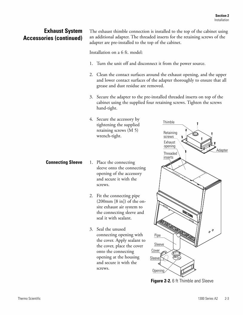
The exhaust thimble connection is installed to the top of the cabinet usingan additional adapter. The threaded inserts for the retaining screws of theadapter are pre-installed to the top of the cabinet.
Installation on a 6 ft. model:
1. Turn the unit off and disconnect it from the power source.
2. Clean the contact surfaces around the exhaust opening, and the upperand lower contact surfaces of the adapter thoroughly to ensure that allgrease and dust residue are removed.
3. Secure the adapter to the pre-installed threaded inserts on top of thecabinet using the supplied four retaining screws. Tighten the screwshand-tight.
4. Secure the accessory bytightening the suppliedretaining screws (M 5)wrench-tight.
1. Place the connectingsleeve onto the connectingopening of the accessoryand secure it with thescrews.
2. Fit the connecting pipe(200mm [8 in]) of the on-site exhaust air system tothe connecting sleeve andseal it with sealant.
3. Seal the unusedconnecting opening withthe cover. Apply sealant tothe cover, place the coveronto the connectingopening at the housingand secure it with thescrews.
1300 Series A2 2-3Thermo Scientific
Section 2Installation
Connecting Sleeve
Exhaust SystemAccessories (continued)
Thimble
Retainingscrews
Exhaustopening
Threadedinserts
Pipe
Sleeve
Cover
Sleeve
Opening
Adapter
Figure 2-2. 6 ft Thimble and Sleeve

2-4 1300 Series A2 Thermo Scientific
Section 2Installation
Moving the Unit To prevent tilting, always transport the cabinet separate from the stand,using equipment capable of supporting the weight, even for a move withina building.
Caution When moving the unit, lift only at the lift points shown in Figure2-3. s
Caution Do not allow the weight of the cabinet to rest on the drain pan! s
Warning The weight of the window is balanced by the counterweight onthe back of the cabinet. Do not move the unit unless the counterweighthas been locked in place with the shipping screws (see Figure 3-2). s
Figure 2-3. Lift points

Install the service valve(s) by removing thecenters of the plug (brass) or piercing it atthe pre-determined location (plastic).
Installation spacing on side of unit:A1 = 8.9 in. (225 mm)A2 = 4.1 in. (105 mm)S1 = 10.8 in. (275 mm)S2 = 3.9 in. (100 mm)
Note The plugs must only be used for theinstallation of service valves in accordancewith the applicable national regulations. s
At each side panel, service valves can be installed through the two servicevalve port plugs (P/N 24909-exterior port plug, 249096-interior portplug).
1. Move the front window to the fully open position.
2. Turn the unit off and disconnect it from the power source.
3. Score the plug circularly at the pre-determined point (inside andoutside). Remove the centers.
4. Referring to Figure 2-5 on the following page, slide the gasket and thebezel onto the threaded pipe of the service valve. Apply a thin bead ofsilicon to the inner flange of the service valve.
5. From inside the sample chamber, slide the service valve through thedesired plug.
6. From the outside, slide the other gasket and the washer onto theservice valve threaded pipe and apply a thin bead of silicon to theouter flange of the service valve.
7. Secure the service valve to the side panel using the nut.
8. Establish the connection to the supply line using a union nut.
Note If a service valve is removed, the service valve port plug should bere-installed. s
1300 Series A2 2-5Thermo Scientific
Section 2Installation
Service ValveConnections
A1
S1
S2
Service valve
port plugs
A2
Figure 2-4. Valve Location

2-6 1300 Series A2 Thermo Scientific
Section 2Installation
Valve Connections(continued)
Service valveService valve
port plugs
BezelThreaded
pipe
Nut
Washer
Figure 2-5. Valve Assembly and Installation

Universal piping is a factory-installed option. The piping can be installedon either, or both, sides. Access points, depending on selected installation,are available on the top, side or bottom of the cabinet. Pipe threads are1/4” FPT. Refer to illustration below.
1300 Series A2 2-7Thermo Scientific
Section 2Installation
Universal PipingConnections
Figure 2-6. Possible Universal Piping Access Points
top access points
right side
access points
bottom of cabinet
access points
bottom of cabinet
access points
left side
access points

1300 Series A2 3-1Thermo Scientific
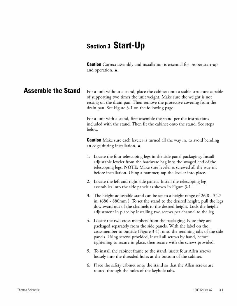
Section 3 Start-Up
Caution Correct assembly and installation is essential for proper start-upand operation. s
For a unit without a stand, place the cabinet onto a stable structure capableof supporting two times the unit weight. Make sure the weight is notresting on the drain pan. Then remove the protective covering from thedrain pan. See Figure 3-1 on the following page.
For a unit with a stand, first assemble the stand per the instructionsincluded with the stand. Then fit the cabinet onto the stand. See stepsbelow.
Caution Make sure each leveler is turned all the way in, to avoid bendingan edge during installation. s
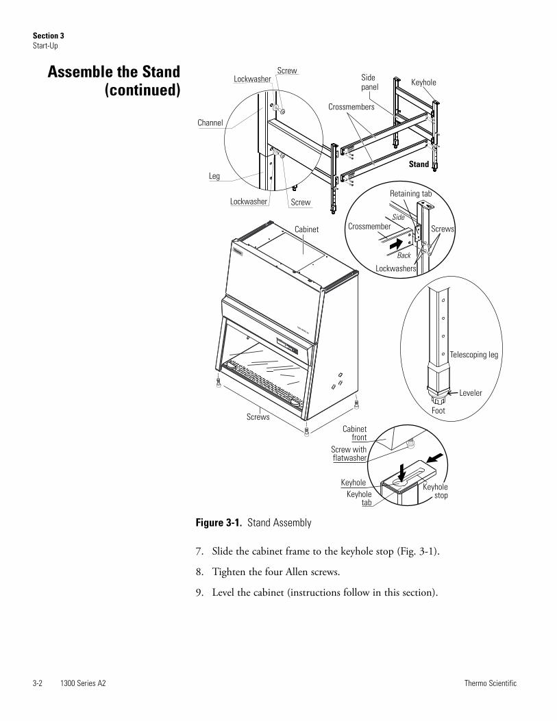
1. Locate the four telescoping legs in the side panel packaging. Installadjustable leveler from the hardware bag into the swaged end of thetelescoping legs. NOTE: Make sure leveler is screwed all the way in,before installation. Using a hammer, tap the leveler into place.
2. Locate the left and right side panels. Install the telescoping legassemblies into the side panels as shown in Figure 3-1.
3. The height-adjustable stand can be set to a height range of 26.8 - 34.7in. (680 - 880mm ). To set the stand to the desired height, pull the legsdownward out of the channels to the desired height. Lock the heightadjustment in place by installing two screws per channel to the leg.
4. Locate the two cross members from the packaging. Note they arepackaged separately from the side panels. With the label on thecrossmember to outside (Figure 3-1), onto the retaining tabs of the sidepanels. Using screws provided, install all screws by hand, beforetightening to secure in place, then secure with the screws provided.
5. To install the cabinet frame to the stand, insert four Allen screwsloosely into the threaded holes at the bottom of the cabinet.
6. Place the safety cabinet onto the stand so that the Allen screws arerouted through the holes of the keyhole tabs.
Assemble the Stand
3-2 1300 Series A2 Thermo Scientific
Section 3Start-Up
Cabinet
Screws
Cabinetfront
Screw withflatwasher
Keyholetab
KeyholeKeyhole
stop
Stand
KeyholeSidepanel
Crossmembers
Screw
Screw
Leg
Channel
Crossmember
Retaining tab
Screws
Side
Back
Leveler
Foot
Telescoping leg
Lockwasher
Lockwasher
Lockwashers
Figure 3-1. Stand Assembly
Assemble the Stand(continued)
7. Slide the cabinet frame to the keyhole stop (Fig. 3-1).
8. Tighten the four Allen screws.
9. Level the cabinet (instructions follow in this section).

1300 Series A2 3-3Thermo Scientific
Section 3Start-Up
UnlockCounterweight
The window counterweight is secured to the back of the cabinet to protectit from damage during shipping.
Caution The counterweight onthe cabinet back compensates forthe weight of the front window.Do not try to move the frontwindow before the counterweighthas been unlocked. s
Warning After unlocking, keephands and fingers away from themotion range of thecounterweight! s
To unlock the counterweight,remove the shipping screws (seelocation arrows in Figure 3-2) andretain them for future shippingneeds.
Warning One person should hold the counterweight while a secondperson removes the screws. This facilitates screw removal and avoids thepossibility of stripping the screws. s
Note The cabinet should be leveled only after it has been located in thedesired working location. s
For cabinets without a stand, place a bubble level onto the work traysurface and adjust the cabinet until the level indicates an absolutelyhorizontal position in all directions.
For cabinets with an optional stand, place a bubble level onto the worktray and adjust the four levelers of the stand using an open end oradjustable wrench until the bubble level indicates an absolutely horizontalposition in all directions. Check from right to left, and from back to front.
Level the Cabinet
Counterweight
Figure 3-2. Unlocking the Counterweight
Warning Contact with electrical components can cause a lethal shock.
Warning Before connecting the unit to a power source, check plug andpower cord for possible damage. Do not use damaged components toconnect the unit to the power source! s
1. Before connecting the unit to the power source, verify that the voltageof the outlet matches the specifications on the cabinet nameplate. If theratings given for voltage (V) and maximum current (A) do not match,do not connect the unit to the power source.
2. Connect the power cord to a properly grounded and fused outlet. The outlet must be fused separately, using a fusible link T15A or usinga circuit breaker B15. If the configuration of the receptacle does notmatch the power plug, consult a qualified electrician to replace orinstall the correct receptacle.
3. Make sure that the power cord is routed away from the counterweightand cable guide. The left side of the cabinet has additional fasteningpoints that can be used for routing the power cord.
4. Make sure that the power cord is not stretched or pinched.
To protect from accidental disconnection, the power source outlets shouldbe located out of casual reach and be accessible only to authorized persons.Ideally, the outlet should be located above the cabinet to avoid accidentalshut-off.
The power supply cord is the mains disconnect.
If the unit includes service valves (gas, water), the valves must be installedproperly to ground to the unit’s main ground.
On connection to the power source, place the window at the workingposition and wait until all lights on the display are green. The cabinet isnow ready for operation and can be operated using the control panel.
3-4 1300 Series A2 Thermo Scientific
Section 3Start-Up
Power Connection
Warning Do not operate the unit before initial operation, installation andcertification tests have been performed. s
The installation test must be performed in accordance with thespecifications of NSF/ANSI 49, 2004. The cabinet may be operated as aClass II biological safety cabinet, in accordance with NSF/ANSI 49 2004,if the unit functions listed below were verified and if the test results arewithin the safety value tolerances as specified in NSF/ANSI 49 2004,Annex F.
• Inflow velocity profile test• Downflow velocity profile test• HEPA filter leakage test• Airflow smoke pattern test• Site installation assessment tests• A repeat test must also be performed annually, after repairs to the unit or
after location changes (more than 2 in. [5cm]).• The operator should request a written test report from the authorized
service technician.
Warning The operational safety of the unit, particularly the personal andproduct protection, are guaranteed only if all safety functions of the unithave been tested and approved. s
Caution Thermo will not warrant operational safety if the unit is operatedwithout the required installation and certification test, or if these tests andrepeat test are not performed by adequately trained and authorizedpersonnel. s
Caution The initial operation with subsequent installation test does notinclude any decontamination measures. The sample chamber and anyaccessories required must be disinfected and cleaned in accordance withthe hygiene guidelines set forth for the desired application. s
1300 Series A2 3-5Thermo Scientific
Section 3Start-Up
Installation Tests

Caution Service and certification must be performed by qualifiedpersonnel. s
Biological safety cabinet certification consists of a series of tests designed toverify that the cabinet is performing within operating parametersestablished by the manufacturer. To assure that a biological safety cabinet isoperating as intended, each cabinet should be field-tested at the time ofinstallation and at least annually thereafter. Cabinets should be re-certifiedwhenever HEPA filters are changed, internal maintenance is performed, orthe unit is relocated.
Three industry-related organizations maintain lists of companies andindividuals who are active in the certification industry. You may contactthese organizations at the addresses listed below.
NSF International (NSF) and International Air Filtration CertifiersAssociation (IAFCA) sponsor certifier accreditation programs. Accreditedcertifiers have demonstrated proficiency at testing biological safety cabinetsby successfully completing written and/or practical examinations.
Biohazard Cabinet Field Certifier ProgramNSF InternationalPO Box 130140789 N. Dixboro RdAnn Arbor, MI 48113-0140Telephone (734) 769-8010 Or (800) NSF-MARKFax (734) 769-0109http://www.nsf.org/Certified/Biohazard-Certifier
IAFCAPO Box 12155Columbus, OH 43212Telephone (888) 679-1904Fax (614) 486-1108http://www.iafca.com/certifier.html
3-6 1300 Series A2 Thermo Scientific
Section 3Start-Up
Locating a Certifier

The Controlled Environment Testing Association (CETA) is a tradeassociation devoted to promoting and developing quality assurance withinthe controlled environment testing industry. A list of active members isavailable by contacting the organization.
Controlled Environment Testing Association1500 Sunday DriveSuite 102Raleigh, NC 27607Telephone (919) 787-5181Fax (919) 787-4916http://www.cetainternational.org/members/corp_indiv.htm
Note Unless certification was expressly called for in the specification,quotes and/or purchase order, the cost for this on-site testing is to be paidfor by the customer. s
1300 Series A2 3-7Thermo Scientific
Section 2Start-Up
Locating a Certifier(continued)

1300 Series A2 4-1Thermo Scientific
Section 4 Operation
The control panel has been divided into three functions; display, keys,status indicators.
The display shows the information below during each operation.• during normal operation, the operating hours of the unit,• during safe work mode, the downflow and exhaust air velocities,• with UV light (optional) timer on, the remaining disinfection time.
Press the Hours/Velocities key to switch between the operating hours, andthe downflow and exhaust air velocities in safe work mode (with windowin the open, safe operating work position).
DisplayOn/Off
Hours/
Air velocitiesLight
On/Off
Outlets
On/Off
UV Light
On/OffSilence
Reduced
blower speed
Airflow
NOT
steady
(red)
Airflow
steady
green)
Window
NOT in
work
position
(red)Window
in work
position
(green)
Red
Red
Yellow
YellowGreen
Green
Figure 4-1. Control Panel Functions
4-2 1300 Series A2 Thermo Scientific
Section 4Operation
To enable (I) / disable (0) the alarm ringback function, follow the stepsbelow.
In OFF mode, press and hold the Hours/Air Velocities key forapproximately five seconds. The display momentarily shows the operatinghours, then the switching state:
I = alarm acknowledge function enabled,0 = alarm acknowledge function disabled.
Light key turns the sample chamber light on and off.
The On/Off key turns power to the unit on or off.
Outlet On/Off key turns power to the internal outlets on and off (the blueLED indicates that voltage is present).
UV Light key turns the UV light on and off. The yellow LED indicatesthe UV light has been activated. If the optional UV light is not installed,this key has no function.
When the optional UV light is turned on, the display alternates betweendIS and the remaining preset time.
Silence key for muting the audible alarm.
1. To turn the unit on, press and hold the ON key until the blowers start(audible blower operation), and the status indicators (LEDs)illuminate.
Note A several seconds delay may occur between key actuation and unitresponse. s
2. Move the window to the work position (8 or 10 inch opening, modeldependent - see data label and first page of this manual). The correctposition is reached when the green LED “front window is in workposition” illuminates. The side guide rails have markings that definethe lower edge of the front window. These markings can be used as anadditional orientation aid.
3. Wait until the green LED “airflow is steady” illuminates.
4. The unit is ready for operation.
Unit Start-Up
1300 Series A2 4-3Thermo Scientific
Section 4Operation
The following are the operating modes for this unit.• Calibration mode• OFF mode• Window open mode• Working mode • Standby mode• UV mode
Off mode means the unit is in an idle state. The unit is turned off(blowers are off ). The sample chamber light is enabled. The unit isconnected to a power source. The blue LED “internal power supplyactivated” is lighted.
Window open mode is the state in which the window is open andpositioned outside of the working position (8 or 10 inches, modeldependent - see data label and first page of this manual). To install orremove accessories, the front window can be moved to the maximum openposition. For cleaning, the front window can be lowered beyond the closedposition (see Use of the Window, Section 1).
The air system blowers are switched on with the red LED “airflow volumesteady” lighted. The front window is not in the work position, with the redLED “front window not in work position” is lighted. The sample chamberlight is enabled. The power supply for the internal outlets is enabled withthe blue LED “internal power supply on” is lighted.
Working mode is active when the front window is in the working positionand the air system is operating steadily. The green LEDs “front window isin work position” and “airflow steady” are lighted.
The markings on the side guide rails and the lower edge of the frontwindow are at the same height with no audible alarm signal.
The sample chamber light and power for the internal outlets are enabledwith the yellow LED “internal power supply activated” is lighted.
The RS-232 contact is open. The display shows operating hours,downflow velocity and exhaust air velocity.
Standby mode is the state in which the window is closed with the blowervelocity reduced. The red LED “front window not in work position” andthe blue LED “airflow reduced” are lighted.
The sample chamber illumination is enabled. The internal power supply inthe sample chamber is enabled. The red LED “airflow not steady” and theblue LED “internal power supply activated” are lighted.
Operating Modes

The biological safety cabinet can be turned off (OFF mode) by pressingand holding the ON key for five seconds until all LEDs are off.
UV mode means the UV light is on with a set timer running. The windowmust be in the closed position to protect against UV radiation. The lightwill not turn on with the window open.
The yellow LED “UV disinfection routine activated” is lighted until thepreset time has elapsed. Then, the UV lights turn off automatically, andthe status indicator turns off.
The sample chamber illumination is disabled in this mode, as well as theinternal power source in the sample chamber.
1. Move the front window to the maximum opening position. Thisautomatically switches the blowers to full speed.
2. Install needed work materials within the sample chamber work area.Avoid blocking the front air intake grille.
3. Move the front window to the work position (the green status indicatorFront Window in Work position is illuminated) and wait until theairflow has stabilized (the green status indicator Airflow steady isilluminated).
Warning Personal and product protection is ensured only if the airflowsystem of the device is working properly. If the alarm system issues a failuremessage for more than a few minutes while the front window is in thework position, stop all applications that may jeopardize worker safety. s
4. Load the work tray with samples.
5. For work breaks or for extended experimental phases without manualintervention, switch the device to standby mode by closing thewindow.
4-4 1300 Series A2 Thermo Scientific
Section 4Operation
Operating Modes(continued)
Loading the Chamber
Failure messages are shown on the display as codes ER 3 to ER 7. If one ofthese codes appears on the display, contact Technical Services immediately.
To isolate the cause of the failure, perform the following tests.
• Check to see if the exhaust opening on top of the cabinet is blocked.
• Ensure that the in-house exhaust air system is activated, if applicable .
• Close doors and windows in the laboratory to prevent drafts.
• Turn off devices in the vicinity of the biological safety cabinet thatcause air turbulence, or emit excessive heat.
• Open flames in the sample chamber may impair airflow conditions.
1300 Series A2 4-5Thermo Scientific
Section 4Operation
Error Messages
The observance of work rules ensures a minimum of operational safetywhen handling the biological safety cabinet.
Before starting a procedure, take off all jewelry, put on required personalprotective equipment (gloves, goggles, apron), and clean and disinfect thesample chamber surfaces at regular intervals.
During operation:
• Place samples only within the defined work area of the work tray.
• Do not place unnecessary items into the sample chamber.
• Use only disinfected and cleaned accessories for the work process.
• Do not cause air turbulence by quick hand, arm or body movementsin the sample chamber or in front of the work opening.
• Do not place accessories into the sample chamber that cause airturbulence or emit excessive heat.
• Do not block air circulation at the ventilation slots of the work tray.
WorkingRecommendations

• A height-adjustable working chair with an adjustable seat back shouldbe used during extended work periods at the cabinet.
• When the forearm rests on the armrest, is should be in a nearlyhorizontal position.
• When the upper leg is in a horizontal position, the angle betweenupper and lower leg should not exceed 90°.
• To compensate between the floor and sitting height, a footrest shouldbe used. The minimal effective size of the footrest should be 18 x 14 in(45 x 35cm). The slope should be adjustable to within a range from 5°to 15°. The adjustable height should extend to a minimum of 4 in(11cm) above the floor.
After completing a procedure,
1. Remove samples from the sample chamber and store them properly.
2. Clean and disinfect the sample chamber surfaces, including the worktray and the drain pan.
3. Clean and disinfect all accessories.
Working (continued )
4-6 1300 Series A2 Thermo Scientific
Section 4Operation
Forearm
on armrest
horizontal
Upper leg horizontal
90° between upper
and lower leg
Slope 5° to 15°
Minimum 4 inches
off floor
15°
Figure 4-2. Sitting Posture
1300 Series A2 4-7Thermo Scientific
Section 4Operation
Procedure Interrupt To interrupt a work process:
1. Remove all samples from the chamber and store them properly.
2. Remove any accessories from the chamber, and clean and disinfectthem.
3. Clean and disinfect the chamber surfaces, work tray, and drain pan.
4. Turn the unit to standby mode by first closing the window. Then pressand hold the ON key until the indicators are off (the right indicatorsegment of the display shows a dot to indicate that voltage is present).
Caution For safety reasons, the blowers can be switched off only when thefront window is closed. s
If the device is not to be used or is to be stored for an extended period oftime, it must be completely decontaminated.
Warning To shut the device down, the sample chamber must bedisinfected completely and the plenum, including the filters, must bedecontaminated using the appropriate and authorized procedures. s
1. After the device has been decontaminated, close the windowcompletely.
2. Disconnect the unit from the power source.
All components with the exception of the HEPA filters can be discardedafter having been thoroughly cleaned and decontaminated. The HEPAfilters must be discarded in accordance with the applicable national, stateand local regulations for special solid waste.
Warning As this unit can be used for processing and treating infectioussubstances, it must be decontaminated prior to disposal, in accordancewith acceptable standards and procedures.
Unit Shut-down
Unit Disposal

1300 Series A2 5-1Thermo Scientific
Section 5 Cleaning / Decontamination
Several procedures can be used for decontaminating the biological safetycabinet. Which procedure is selected, depends on the potential riskimminent in the agents used, and/or the degree of cleanliness required byan experiment or work process.
One possible decontamination procedure is to clean, rinse and dry with adisinfection liquid or spray, and sterile distilled water.
UV disinfection can also be used. It is particularly suited as a more intensedisinfection after the above procedure.
Autoclaving (sterilization with steam) can be used for treating theremovable stainless steel components. The bezels of the UV lights, thework tray(s), armrests and paper catch grids are autoclavable components.
Disinfection with formaldehyde can be performed if a sterile samplechamber is required for the work procedure. This sterilization procedure ismandatory before filters are replaced, or before the unit is discarded.
Stainless steel is a combination of many different metals including iron andchromium. Iron, the primary element in stainless steel, tends to corrode(rust) when in its natural state. The chromium content in stainless steelprevents corrosion.
Stainless steel is not corrosion or rust proof, just resistant to stains, orstains “less”. The chromium, in the presence of oxygen, forms a tough,invisible, passive layer of chromium oxide film on the steel surface. Ifdamaged mechanically or chemically, this film is self-healing as long as ithas enough oxygen. The presence of any liquid or solid that remains incontact with the stainless steel for a prolonged time can prevent oxygencontact and promote corrosion, as can prolonged contact with cleaners ordisinfectants containing chlorine, ammonia, iodine or other caustic agents.
Care and Cleaning ofStainless Steel
5-2 1300 Series A2 Thermo Scientific
Section 5Cleaning and Decontamination
Cleaning/Caring forStainless Steel (cont.)
Cleaning and Caringfor Coated Surfaces
1. To properly care for stainless steel, use cleaners and disinfectants free ofcaustic agents such as chlorine, iodine and ammonia.
2. Always follow the application of any cleaner or disinfectant with aminimum of two clean distilled water rinses, then a thorough dryingwith a clean soft cloth. By rinsing with distilled water and drying, anyremaining residue is removed from contact with the stainless steel.
Caution Never use abrasive cleaners, scouring pads or steel wool whencaring for stainless steel. s
If the stainless steel does become stained, corroded or rusted, the irondeposits left on the surface can be removed by neutralizing them withthe passivation process. This process uses an acid to neutralize the “freeiron” deposits left on the steel where there has been deprivation ofoxygen. This stops the spread of the corrosion or rust. It will notreturn the stainless steel to its original finish.
All the coated surfaces of this equipment are powder coated. Powdercoating is a method of applying a dry powder to electro-statically chargedmetal, then baked in an oven where the dry powder molecules are meltedand fused together. This is by far the most durable finish available todayand, if cared for properly, will last for many years. The coated surfacesshould be cleaned with a neutral detergent and rinsed twice with cleandistilled water, then dried thoroughly with a clean soft cloth. Cleaning ordisinfecting coated surfaces without rinsing with clean distilled water anddrying thoroughly will result in smearing, streaking and dulling of thecoated surfaces. Never use abrasive cleaners, scouring pads or steel wool.If the coated surfaces do become dull, streaked, smeared or marred in someother way, there is no known method to restore the finish.
1. Remove all samples from the chamber and store them properly.
2. Remove accessories from the cabinet and disinfect them using thedisinfection procedure recommended by the manufacturer of theaccessory.
3. The work tray(s) and stainless steel components can be removed fromthe chamber and disinfected separately.
4. Clean all chamber surfaces with disinfectant.
5. Do not remove the optional UV lights from the sockets. Cleanthoroughly with a damp cloth. Do not saturate. Be sure to drycompletely.
1. Rinse all surfaces twice with clean distilled water.
2. Discard any liquid from the drain pan. Rinse pan.
3. Dry all chamber surfaces completely.
UV disinfection can be performed by using the optional factory installedUV light.
To start the UV disinfection procedure,
1. Close the front window, the air system operates in the reduced mode(blue LED illuminated).
2. Press the UV key on the control panel. The display alternates betweendIS and the remaining disinfection time.
To interrupt or cancel the UV disinfection procedure, just press the UVkey (the display shows the operating hours) and slide the window up.
Rinsing
Disinfection
1300 Series A2 5-3Thermo Scientific
Section 5Cleaning and Decontamination
UV Disinfection AfterCleaning
Disinfection withFormaldehyde
Clean ExteriorSurfaces
Clean Window
5-4 1300 Series A2 Thermo Scientific
Section 5Cleaning and Decontamination
The UV disinfection time is preset. However, this setting can be changed,if required.
1. Turn the unit on and move the window to the work position.
2. Press and hold the UV key until the preset time is displayed.
3. To increase the time, press the internal power supply key. Each timethe key is pressed, the time increases by 30 minutes.
4. To reduce the time, press the sample chamber light key. Each time thekey is pressed, reduces the time by 30 minutes.
5. To save the value, press the UV key. The display shows the operatinghours again.
Note The UV disinfection time is adjustable from 0:00 (disabled) to 24:00hours. s
Warning Decontamination with formaldehyde must be performed inaccordance with the specifications of NSF/ANSI 49, 2004, Annex G. Asthis procedure has considerable risks, it must only be performed byspecially trained and authorized service personnel! s
Clean the exterior surfaces of the cabinet using a solution of tepid waterand commercially available mild dishwashing agent. Then, dry all surfaceswell, using a soft, clean cloth.
For cleaning, the window can be lowered beyond the closing position (Useof the Window, Section 1).
Creating a gap at the window’s upper edge ensures that the upper portionof the window can be cleaned and/or disinfected. Use a commerciallyavailable window cleaner to clean the window.
Change the UVDisinfection Time
1300 Series A2 5-5Thermo Scientific
Section 5Cleaning and Decontamination
Clean the drain pan, using a solution of tepid water and commerciallyavailable mild dishwashing agent.
1. Remove the work tray(s) from the chamber.
2. Clean thoroughly to remove any residues and/or deposits.
3. Wipe the drain pan, using a clean cloth and plenty of clean water.
4. Discard any liquid in the drain pan. Rinse and dry thoroughly.
Note After cleaning, make sure that all cleaning product has been removedcompletely from the drain pan. s
5. Re-install the work tray.
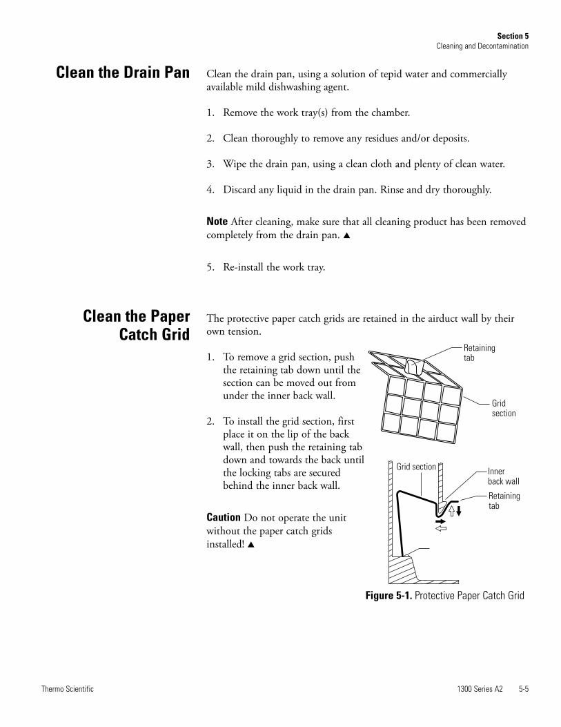
The protective paper catch grids are retained in the airduct wall by theirown tension.
1. To remove a grid section, pushthe retaining tab down until thesection can be moved out fromunder the inner back wall.
2. To install the grid section, firstplace it on the lip of the backwall, then push the retaining tabdown and towards the back untilthe locking tabs are securedbehind the inner back wall.
Caution Do not operate the unitwithout the paper catch gridsinstalled! s
Clean the Drain Pan
Clean the PaperCatch Grid
Retainingtab
Gridsection
Innerback wall
Retainingtab
Grid section
Figure 5-1. Protective Paper Catch Grid


Section 6 Maintenance
The Thermo Performance Factor, the test routine for the biological safetycabinet, determines the cabinet's system status by way of adjusting variousdevice parameters.
An inspection of the device should be performed if the indicated ThermoPerformance Factor drops to a value below 60%. In this event, thecorresponding LEDs (yellow or red) of the performance indicator light.
Regardless of the indicated Thermo Performance Factor, the biologicalsafety cabinet should be certified annually.
The annual certification consists of the following checks:• Electrical safety in accordance with national regulations.• Functional test of the device.• Checking all components for possible damage.• Checking the filter state.• Verifying device air flows • Checking the airflow conditions.• Repeat test in accordance with NSF/ANSI 49/2004.
Warning The diffuser plate on the chamber ceiling serves as protection forthe downflow filter and prevents refluxing of downflow air. Whenscanning the filter surface for a leak test, the perforated plate must beremoved. s
1300 Series A2 6-1Thermo Scientific

As filter replacement is an interference with the safety system of the unit,filters must only be replaced by adequately trained and authorized servicepersonnel.
Warning For any service work in a potentially contaminated section of thebiological safety cabinet, the unit must first be decontaminated. s
The sample chamber is illuminated by one (4 foot units) or two (6 footunits) fluorescent bulbs. The spring-loaded sockets of the fluorescent bulbsare installed in the light mounting frame in the sample chamber (Fig. 6-1).
1. Switch the unit off and disconnect it from the power source.
2. Move the window to the cleaning position (below closed position) toensure a sufficient gap between the window’s upper edge and the lightdome.
3. The fluorescent bulbs are installed in rotating sockets. To remove,rotate the bulb counterclockwise to disengage the latch and remove itfrom the sockets.
4. To install, slide the bulb contact pins into the rotating socket groovesand rotate the bulb clockwise to latch the sockets.
The optional, factory installed UV light is installed in the chamber ceilingimmediately behind the window. The UV light should be replaced after1500 operating hours. See Figure 6-1.
1. Turn the unit off and disconnect it from the power source.
2. Move the window to the maximum open position.
3. Wear protective gloves to prevent skin oils from burning into the bulb. The UV bulb is installed in rotating sockets. To remove, rotate thebulb counterclockwise to disengage the latch and remove it from thesockets.
4. To install, slide the bulb contact pins into the rotating socket groovesand rotate the bulb clockwise to latch the sockets.
6-2 1300 Series A2 Thermo Scientific
Section 6Maintenance
Service
Sample Chamber Lights
Optional UV Lights

1300 Series A2 6-3Thermo Scientific
Section 6Maintenance
Caution Remote alarm systems can be retrofitted and integrated into theunit controls. Specifically, modifications to the filter system and resultingchanges of the airflow may impair personal and product protection. Suchwork must be performed only by authorized service personnel. s
The entire cabinet with the exception of the HEPA filters can be discardedafter having been thoroughly cleaned and decontaminated. The HEPAfilters must be discarded in accordance with the applicable national, stateand local regulations for special solid waste.
Warning As this unit can be used for processing and treating infectioussubstances, it may become contaminated. Prior to disposal, the entire unitwith filters must be decontaminated in accordance with acceptablestandards and procedures. s
Replacements andRepairs
UV light
Chamber light
Figure 6-1. Light Replacement
Unit Disposal

Section 7 Specifications
1300 Series A2 7-1Thermo Scientific
Dimensions
Description
4ft Models (10” window opening work position)1345, 1346, 1354, 1355, 1356, 1375, 1376, 1384,1385, 13864ft Models (8” window opening work position)1305, 1306, 1325, 1326, 1335, 1336, 1395, 1396
6ft Models (10” window opening work position)1347, 1348, 1357, 1358, 1359, 1377, 1378, 1387,1388, 13896ft Models (8” window opening work position) 1307, 1308, 1327, 1328, 1337, 1338, 1397, 1398
Exterior dimensions
Width mm / in 1300 / 51.2 1900 / 74.8
Depth mm / in 795 / 31.3 802 / 31.6 802 / 31.6 802 / 31.6
Height mm / in 1520 / 59.8
Interior dimensions
Width mm / in 1200 / 47.24 1800 / 70.9
Depth mm / in 630 / 24.8 627 / 24.7 627 / 24.7 627 / 24.7
Height mm / in 780 / 30.7 780 / 30.7 780 / 30.7 780 / 30.7
Front window
Working position mm / in 254 / 10 - pertains to all 4’ & 6‘ models listedabove with 10” window work position
203 / 8 - pertains to all 4’ & 6’ models listed abovewith 8” window work position
Opening max. mm / in 500 / 19.7
Working area height with adjustable height stand
Seat position mm / in 750 / 29.5
Side wall access ports
Diameter mm / in 23 / 0.91 23 / 0.91
Distance lower edge mm / in 150 / 5.91 150 / 5.91
Distance from back panel
First access port mm / in 275.3 / 10.8 275.3 / 10.8
Second access port mm / in 377 /14.8 377 /14.8
Third access port mm / in 275.3 / 10.8 275.3 / 10.8

7-2 1300 Series A2 Thermo Scientific
Section 7Specifications
Ambient conditions
Temperature
Max. ambient temp during operation °C / °F 40 / 104
Min. ambient temp during operation °C / °F 10 / 50
Humidity
Max. humidity / operation % r.H. 90, non-condensing
Max. humidity / storage % r.H. 95
Heat dissipation to environment
Room temperature 20°C kJ/s / BTU/s4ft models 10": 0.2 / 0.194ft. models 8": 0.18 / 0.17
6ft. models 10": 0.4 / 0.386ft. models 8": 0.36 / 0.34
Room temperature rise
Above room temp with window closed °K < 2 < 2
Ergonomics
Noise level* dB(A)4ft. models 10”: 63, ±24ft. models 8": 62, ±2
6ft models 10”: 65, ±26ft. models 8": 64, ±2
*The noise level was determined in accordance with NSF/ANSI 49. 2004. The measurement uncertainty is within a range of ± 2 dB.
Volume, weights, and loads
Description
4ft Models (10” window opening workposition) 1345, 1346, 1354, 1355, 1356,1375, 1376, 1384, 1385, 13864ft Models (8” window opening workposition) 1305, 1306, 1325, 1326, 1335,1336, 1395, 1396
6ft Models (10” window opening workposition) 1347, 1348, 1357, 1358, 1359,1377, 1378, 1387, 1388, 13896ft Models (8” window opening workposition) 1307, 1308, 1327, 1328, 1337,1338, 1397, 1398
Volume
Drain pan l / gal 20 / 5.3 30 / 7.9
Weights
Cabinet kg / lb 170 / 375 230 / 507
Stand kg / lb 30 / 66 35 / 77
Loads
Maximum load on work surface kg / lb 25 / 55
Maximum load on overall working area kg / lb 50 / 110 75 / 165

1300 Series A2 7-3Thermo Scientific
Section 7Specifications
Electrical data
Models
120V Models - 4 ft / 6 ft1305, 1307, 1325, 1327, 1335, 1337, 1345,
1355, 1375, 1385 / 1347, 1357, 1377, 1387,1395, 1397
230V Models - 4 ft / 6 ft1306, 1308, 1326, 1328, 1336, 1338, 1346,
1354, 1356, 1376, 1384, 1386 / 1348, 1358,1359, 1378, 1388, 1389, 1396, 1398
Voltage
Rated voltage V 1/N/PE AC, 120V, 50/60 Hz 1/N/PE AC, 230V, 50/60 Hz
Blower voltage V 48 V DC
Current
Power consumption maximum A 8 / 10 7 / 8
Leakage current IEC 61010-1,UL61010-1 mA < 3.5
Motherboard fusing A 2 x T 15 A
Outlet fusing A 2 x T 5 A
On-site fusing A Circuit breaker 15 A / Fuse T 15 A
Power
Power input maximum W 1130 / 1700 1440 / 2000
Protection
Protection class I
Protection type IP 20
Overvoltage category (IEC 61010-1,UL61010-1) II
Contamination degree (IEC 61010-1,UL61010-1) 2
Connecting lines
Mains connection Power Cord (3.7 m / 12.1 ft)
7-4 1300 Series A2 Thermo Scientific
Section 7Specifications
Airflow system
Description
4ft Models (10” / 8” window opening workposition) 1305, 1306, 1325, 1326, 1335,1336, 1345, 1346, 1354, 1355, 1356, 1375,1376, 1384, 1385, 1386, 1395, 1396
6ft Models (10” / 8” window opening workposition) 1307, 1308, 1327, 1328, 1337,1338,1347, 1348, 1357, 1358, 1359, 1377,1378, 1387, 1388, 1389, 1397, 1398
Airflows / Airflow velocities
Inflow m/s 0.53
ft/min 104
Downflow m/s 0.32
Downflow ft/min 63
Air volume
Overall volume flow m³ per h(10”/8”) 1415 / 1298 2128 / 1952
ft³ per min(10”/8”) 834 / 765 1253 / 1149
Downflow volume flow m³ per h(10”/8”) 830 1250
ft³ per min(10”/8”) 489 736
Exhaust air volume flow m³ per h(10”/8”) 585 / 468 878 / 702
ft³ per min(10”/8”) 345 / 276 517 / 413
Filters
Type HEPA
Material Fiberglass
Separability in MPPS % 99.995
Separability at 0,3 µm particle size % 99.999
Downflow
Width mm / in 1220 / 48.03 1830 / 72.05
Depth mm / in 457 / 17.99
Height mm / in 93 / 3.66
Exhaust air
Width mm / in 610 / 24.02 915 / 36.02
Depth mm / in 457 / 17.99 457 / 17.99
Height mm / in 117 / 4.61 117 / 4.61

1300 Series A2 8-1Thermo Scientific
Section 8 Certification Testing
For application in the USA, the unit has been rated as a Class II safetycabinet, Type A2, in accordance with NSF/ANSI Standard 49/2004.
For operation as a unit of said classifications, a certification test and repeattest in accordance with NSF/ANSI Standard 49-2004, Annex F should becompleted at the time of installation, and at least annually thereafter. Asdescribed in Annex F, recertification should be performed whenever HEPAfilters are changed, maintenance repairs are made to internal parts, or thecabinet is relocated. More frequent recertification should be consideredwhen working with safety-critical materials (three to six months).
Nominal value:Default value as specified by Thermo.
Measured value: Value measured at the location of the safety cabinet.
Tolerance: Acceptable deviation from the nominal value.
Average value:The sum of the measuring values divided by the number of tests. Theaverage value is compared to the nominal value.
Setpoint:Acceptable operating value for the inflow and downflow velocities.
Inflow velocity (FPM): Velocity of the air entering the sample chamber opening.
Downflow velocity (FPM): Velocity of the displacement flow circulating through the work chamber.
Exhaust velocity (FPM):Velocity of the airflow discharged through the exhaust filter opening.
Exhaust airflow volume (CFM): Amount of air discharged at the exhaust filter.
Classification of theSafety Cabinet
Test Terms
According to NSF/ANSI Standard 49/2004, tests related to the safety ofthe personnel, product and environment that must be conducted on-sitefor Class II, Type A2 biological safety cabinets, at a minimum frequency ofannually, are;
• downflow velocity profile test
• inflow velocity test
• airflow smoke patterns test
• HEPA filter leak test
• site installation assessment tests
– alarm functions
– exhaust system performance (proper exhaust duct negative pressureand canopy performance).
As described in Annex F, in addition to the above, the following testsperformed at the request of the customer, or at the discretion of thecertification provider.
• comfort and safety tests
– lighting intensity
– noise level
– vibration
– electrical leakage, ground circuit resistance and polarity tests
Note Service with costs: Unless certification was expressly called for in thespecification, quotes and/or purchase order, the cost for this on-site testingis to be paid for by the customer. s
8-2 1300 Series A2 Thermo Scientific
Section 8Certification Testing
Testing

For conducting these tests, Thermo recommends testing equipment of themanufacturers listed below.
Inflow Velocity – DIM Method (Primary)Description: Inflow velocity using the direct inflow measurementmethod (DIM).
Equipment: . . .Shortridge ADM-870, or equivalent . . . . . . . . . .Flow hood Series 8400, or equivalent
Method:
1. Move the front window to the work position (25.4cm/10 in. or20.3cm/8 in., depending on model).
2. Attach the flow hood [1] in the work opening [2] and seal theremaining open areas.
3. Operate the system blowers for approx 20 min.
4. Record at least 5 measurements of the inflow air volume.
5. Average those readings and calculate the inflow velocity (V1) asdescribed below.
1300 Series A2 8-3Thermo Scientific
Section 8Certification Testing
Test Equipment
Testing equipment Manufacturer Application
Smoke tubesMSAPittsburgh, Pennsylvania, 15230
Airflow pattern test
Thermoanemometer TSIShoreview, Minnesota 55126
Downflow velocity test
Digital Safety InspectorOhmic Instruments Co.Easton, Maryland 21601
Electrical leakage and ground resistance tests
GFI Circuit TesterLeviton ManufacturingLittle Neck, New York, 11362
Electrical leakage, ground resistance, and polarity tests
PhotometerAir TechniquesOwing Mills, Maryland, 21117
Filter leak test
Aerosol GeneratorAir TechniquesOwing Mills, Maryland, 21117
Generation of aerosol mist
Vibration MeterQuest TechnologiesOconomowoc, Wisconsin, 53066
Vibration test
Flow HoodAirdata Multimeter Shortridge Instruments. Inc.Scottsdale, Arizona, 85260
Downflow velocity test and alternate method for inflowvelocity using constricted access
Testing Information

Inflow Area:• 4ft Models w/ 10” window opening work position) 1345, 1346, 1354,
1355, 1356, 1375, 1376, 1384, 1385, 1386: Front opening 3.28 sq ft4ft Models (8” window opening work position) 1305, 1306, 1325,1326, 1335, 1336, 1395, 1396: Inflow area for 8 inch models: 2.62 sq ft
• 6ft Models w/ 10” window opening work position) 1347, 1348, 1357,1358, 1359, 1377, 1378, 1387, 1388, 1389: Front opening 4.91 sq ft6ft Models (8” window opening work position) 1307, 1308, 1327,1328, 1337, 1338, 1397, 1398: 3.94 sq ft
Calculation:• Inflow Velocity (V1) = Inflow Air Volume (V2)/Actual Inflow Area (A2)
Acceptance:• 100 – 110 FPM
Correction measures:• Enter the service level and activate S2, change S2 until the desired veloci-
ty is reached and save the new value.• If the velocity can't be adjusted due to clogging of the filters, change the
exhaust filter.• If the filter is in order, change the exhaust blower.
Note Check of alarm limits: If S1 or S2 are changed, the alarm limits S3and S4 must be checked and saved again. s
Inflow Velocity – Constricted Window Method (Secondary)Description: • Inflow velocity measured over several points through a constricted win-
dow.
Equipment: • Thermal Anemometer, or equivalent (hotwire)• Anemometer Probe Holder, part number 1911325
8-4 1300 Series A2 Thermo Scientific
Section 8Certification Testing
Testing Information(continued)

Method:
1. Lower the front window to a height of 3 in. (7.6cm).
2. Operate the system blowers for approximately 20 minutes.
3. Insert the thermal anemometer probe into the probe holder. Place theprobe holder at the window opening work surface, ensuring it is seatedproperly. See Figure 8-1. Adjust the probe so the air passing throughprobe is centered in the window opening (1.5 in. [3.8cm]).
4. Beginning 5.9 inches in fromthe left inside wall, recordsuccessive readings every 5.9inches (7 readings for 4 footmodels and 11 readings for 6foot models).
5. Average those readings andcalculate the inflow velocity(V1) as described below.
Calculation:• Inflow velocity (V1) = average of
actual inflow velocity * factor *0.3 for 10” window openingwork position, 0.375 for 8” win-dow opening work position
Acceptance:• 100 – 110 FPM
Note The thermoanemometerprobe must be positioned at a 10°angle from front vertical andlocated on the same plane as theinside of the window glass.
Multiply the K factor by the averagevelocity reading (V1)
K factor = 0.9929 for 4 ft and0.9918 for 6 ft w/ 10” opening,1.047 for 4 ft and 1.100 for 6 ft w/8” opening.
Refer to the data plate on the lowerright corner of the unit face. s
1300 Series A2 8-5Thermo Scientific
Section 8Certification Testing
Testing Information(continued)
Figure 8-1. Constricted Window Method

Inflow Velocity – Calculating Exhaust Flow (Alternative)Description:• Exhaust velocity measurements to determine inflow velocity.Equipment:• Thermal Anemometer, or equivalent (hotwire)• Freestanding Fixture, or equivalent
Method:
1. Operate the unit in the work position for approximately 20 minutes.
2. Insert the anemometer probe into the probe stand, adjusting the heightto 4 inches (10cm) above the exhaust filter.
3. Record the readings on a horizontal plane 4 inches (10cm) above theeffective exhaust filter area, in a grid pattern not to exceed 4 inches(10cm) x 4 inches (10cm).
4. Average the readings and calculate the inflow velocity.
Grid Pattern:• 4ft Models 1305, 1306, 1325, 1326, 1335, 1336, 1345, 1346, 1354,
1355, 1356, 1375, 1376, 1384, 1385, 1386, 1395, 1396
20 points
• 6ft Models 1307, 1308, 1327, 1328, 1337, 1338,1347, 1348, 1357, 1358,1359, 1377, 1378, 1387, 1388, 1389, 1397, 1398
32 points
Effective Exhaust Filter Area:• 4ft Models 1305, 1306, 1325, 1326, 1335, 1336, 1345, 1346, 1354, 1355,
1356, 1375, 1376, 1384, 1385, 1386, 1395, 1396: 16.8” x 22.8”, 2.66 sq ft• 6ft Models 1307, 1308, 1327, 1328, 1337, 1338,1347, 1348, 1357, 1358, 1359,
1377, 1378, 1387, 1388, 1389, 1397, 1398: 16.8” x 34.8”, 4.06 sq ft
8-6 1300 Series A2 Thermo Scientific
Section 8Certification Testing
Testing Information(continued)
3.94
2.98
2.98
2.98
3.94
3.94 3.74 3.74 3.74 3.74 3.94 inches
6
5.5
5.5
6
6 5.87 5.87 5.87 5.87 5.87 5.87 5.87 5.87 6 inches
Inflow Area:• 4ft Models w/ 10” window opening work position) 1345, 1346, 1354,
1355, 1356, 1375, 1376, 1384, 1385, 1386: Front opening 3.28 sq ft4ft Models (8” window opening work position) 1305, 1306, 1325,1326, 1335, 1336, 1395, 1396: Inflow area for 8 inch models: 2.62 sq ft
• 6ft Models w/ 10” window opening work position) 1347, 1348, 1357,1358, 1359, 1377, 1378, 1387, 1388, 1389: Front opening 4.91 sq ft6ft Models (8” window opening work position) 1307, 1308, 1327,1328, 1337, 1338, 1397, 1398: 3.94 sq ft
Calculation:• Average exhaust velocity (V2) = Sum of measurements / Number of
readings• Exhaust Volume (V3) = Average velocity (V2) x Effective filter area (A3)• Inflow velocity (V1) = Exhaust volume (V3) / Work opening area (A2)
Acceptance:• 100 – 110 FPM
Downflow Velocity – Uniform Cabinet
Description:• Measures the velocity of air flow onto the work surface through the sup-
ply filter.
Equipment:• Thermal Anemometer, or equivalent (hotwire)• Freestanding Fixture, or equivalent
Method:
1. Operate the unit in the work position for approximately 20 minutes.
2. Insert the anemometer probe into the probe stand, adjusting for aheight of 4 inches (10 cm) above the bottom edge of the windowopening while in the work position.
3. Record the readings on a horizontal plane 4 inches (10 cm) above thebottom edge of the window opening while in the work position, in agrid pattern not to exceed 6 inches (15 cm) x 6 inches (15 cm).
1300 Series A2 8-7Thermo Scientific
Section 8Certification Testing
Testing Information(continued)
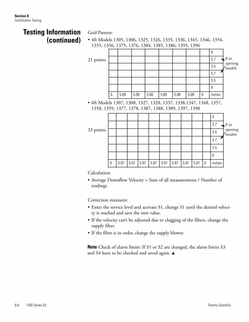
Grid Pattern:• 4ft Models 1305, 1306, 1325, 1326, 1335, 1336, 1345, 1346, 1354,
1355, 1356, 1375, 1376, 1384, 1385, 1386, 1395, 1396
21 points
• 6ft Models 1307, 1308, 1327, 1328, 1337, 1338,1347, 1348, 1357,1358, 1359, 1377, 1378, 1387, 1388, 1389, 1397, 1398
33 points
Calculation:• Average Downflow Velocity = Sum of all measurements / Number of
readings
Correction measures:• Enter the service level and activate S1, change S1 until the desired veloci-
ty is reached and save the new value.• If the velocity can’t be adjusted due to clogging of the filters, change the
supply filter.• If the filter is in order, change the supply blower.
Note Check of alarm limits: If S1 or S2 are changed, the alarm limits S3and S4 have to be checked and saved again. s
8-8 1300 Series A2 Thermo Scientific
Section 8Certification Testing
Testing Information(continued)
6
5.7
5.5
5.7
5.5
6
6 5.87 5.87 5.87 5.87 5.87 5.87 5.87 5.87 6 inches
6
5.7
5.5
5.7
5.5
6
6 5.88 5.88 5.88 5.88 5.88 5.88 6 inches
8 inopeningmodels
8 inopeningmodels
Description:• Determines the integrity of the downflow and exhaust filters.
Equipment:• Aerosol Photometer, or equivalent• Aerosol Generator, or equivalent
Method:
1. Allow the cabinet to operate for approximately 20 minutes.
2. Remove the work tray and protective covers, as appropriate.
3. Introduce the aerosol from the generator in the center rear of the workarea, using a tee fitting to evenly distribute the aerosol.
4. If desired, and if the cabinet has not been used with hazardousmaterials since an effective decontamination, the upstreamconcentration can be measured. If desired, connect the photometersample hose to the appropriate (supply or exhaust) test hoseconnection (exhaust test hose - right side / supply test hose - left side)from under the work tray.
5. Using either the appropriate upstream challenge measurement orcalculated challenge value, set the photometer accordingly.
6. Scan the downstream side and perimeter of the filter as prescribed inNSF/ANSI 49-2004, Annex F.
Acceptance:• Filters scanned – 0.01% of upstream concentration at any point
Method:
1. Set up as in Steps 1 through 5 above
2. In the duct, downstream of the filter, sample in accordance withNSF/ANSI Standard 49, 2004.
Acceptance:
• Filters not scanned – 0.005% of upstream concentration
1300 Series A2 8-9Thermo Scientific
Section 8Certification Testing
HEPA Filter Leak Test
Filters that can beAccessed and Scanned
Filters that cannot beAccessed or Scanned
Description:• Determines the internal and external behavior of the air movement.
Equipment:• Cold smoke (titanium tetrachloride)
Method:• Downflow:
Pass smoke across the centerline of the work surface, 4 inches (10 cm)above the work opening.
• View Screen Retention:Pass smoke 1 inch (2.5 cm) behind the window opening, 6 inches (15cm) above the work opening.
• Work Opening Edge Retention: Pass smoke around the entire outside work opening, approximately 1.5inches (3.8 cm) away from the cabinet.
• Window Seal Test:Pass smoke up both sides and across the top of the window openingfrom inside the work area, approximately 2 inches (5 cm) from theedges.
Acceptance: • No smoke shall have dead spots, reflux or escape the cabinet once drawn
in.
Description:• Refer to UL 61010-1
Description:• Verify the unit is integrated properly into the facility.
8-10 1300 Series A2 Thermo Scientific
Section 8Certification Testing
Airflow Pattern Test
Elect. Leakage , GroundResistance, Polarity Tests
Site InstallationAssessment Tests

Description:• Verify the airflow alarms will activate within 15 seconds when there is a
20% loss.
Equipment:• Thermal Anemometer or equivalent (hotwire)• Anemometer probe holder, part 1911325• Shortridge ADM-870 or equivalent• Flowhood series 8400 or equivalent
Method:• Downflow:
Enter the service level and activate S03.Verify that the average downflow velocity is 20% lower than the ratedvelocity by following the method described previously. Change and saveS03 if needed and leave the service level. Enter the service level againand set S01 to the value of S03 -0.5%. The LED "AIRFLOW STABLE"must change from green to red. Leave the service level without savingthis value by pressing the "acknowledge alarm" key.
•Inflow:Enter the service level and activate S04.Verify that the inflow velocity is 20% lower than the rated velocity byfollowing one method described previously. Change and save S04 ifneeded and leave the service level.Enter the service level again and set S02 to the value of S04 -0.5%.The LED "AIRFLOW STABLE" must change from green to red. Leavethe service level without saving this value by pressing the "acknowledgealarm" key.
Acceptance:• Unit alarm activates within 15 seconds when the downflow and inflow
velocity is set to the correct values and the LED „Airflow STABLE“changes from green to red (as described above).
1300 Series A2 8-11Thermo Scientific
Section 8Certification Testing
Airflow Alarms

Description:• Verify the window alarms are operating properly
Equipment:• Operating manual
Method:• Raise the window 1 inch (2.5 cm) above work position
Acceptance:• Window alarm activates
Description:• Verify the exhaust system is functioning properly
Canopy ConnectionsEquipment:• Cold smoke (titanium tetrachloride)
Method:• Pass smoke around the air gap, to ensure negative pressure exists
Acceptance:• No smoke refluxes back into the room once drawn into the canopy
Direct ConnectionsEquipment:• Manometer, or equivalent
Method:• Measure static pressure in the duct between the unit and balancing
dampers.
Acceptance:• Negative pressure exists
Note Standard: For additional and detailed information regarding thesetests, refer to NSF/ANSI Standard 49, 2004. s
8-12 1300 Series A2 Thermo Scientific
Section 8Certification Testing
Sash Alarms
Exhaust System Performance

1300 Series A2 9-1Thermo Scientific
Device type: Part number:
Serial number: Service number:
Location: Operator's note:
Technician / Company Notes Date Signature

THER
MO F
ISHE
R SC
IENT
IFIC
LAM
INAR
FLO
W E
QUIP
MENT
WAR
RANT
Y US
AT
he
Wa
rra
nty
Pe
rio
d s
tart
s t
wo
we
eks f
rom
th
e d
ate
yo
ur
eq
uip
me
nt
is s
hip
pe
d f
rom
ou
r fa
cili
ty.
Th
is a
llow
s s
hip
pin
g t
ime
so
th
e w
arr
an
ty w
ill g
o in
to e
ffe
ct
at
ap
pro
xim
ate
ly t
he
sa
me
tim
e y
ou
r e
qu
ipm
en
t is
de
live
red
. T
he
wa
rra
nty
pro
tectio
n
exte
nd
s t
o a
ny s
ub
se
qu
en
t o
wn
er.
Du
rin
g t
he
first
thirty
-six
(3
6)
mo
nth
s,
co
mp
on
en
t pa
rts p
rove
n t
o b
e n
on
-co
nfo
rmin
g in
ma
teria
l o
r w
ork
ma
nsh
ip w
ill b
e
repa
ire
d o
r re
pla
ce
d a
t T
he
rmo
’s e
xp
en
se
, in
clu
din
g la
bo
r. I
nsta
llatio
n,
ca
libra
tio
n a
nd
ce
rtific
atio
n is n
ot
co
ve
red
by t
his
wa
rra
nty
ag
ree
me
nt.
Th
e T
ech
nic
al S
erv
ice
s D
epa
rtm
en
t m
ust
be
co
nta
cte
d f
or
wa
rra
nty
de
term
ina
tio
n a
nd
dire
ctio
n p
rio
r
to p
erf
orm
an
ce
of
an
y r
epa
irs.
Exp
en
da
ble
ite
ms,
gla
ss,
filte
rs a
nd
ga
ske
ts a
re e
xclu
de
d f
rom
th
is w
arr
an
ty.
Re
pla
ce
me
nt
or
repa
ir o
f co
mp
on
en
t pa
rts o
r e
qu
ipm
en
t u
nd
er
this
wa
rra
nty
sh
all
no
t e
xte
nd
th
e w
arr
an
ty t
o e
ith
er
the
eq
uip
me
nt
or
to t
he
co
mp
on
en
t pa
rt b
eyo
nd
th
e o
rig
ina
l w
arr
an
ty p
erio
d.
Th
e T
ech
nic
al S
erv
ice
s D
epa
rtm
en
t m
ust
giv
e
prio
r a
pp
rova
l fo
r re
turn
of
an
y c
om
po
ne
nt
or
eq
uip
me
nt.
At
Th
erm
o’s
op
tio
n,
all
no
n-c
on
form
ing
pa
rts m
ust
be
re
turn
ed
to
Th
erm
o p
osta
ge
pa
id a
nd
re
pla
ce
me
nt
pa
rts a
re s
hip
pe
d F
OB
de
stin
atio
n.
TH
IS W
AR
RA
NT
Y I
S E
XC
LU
SIV
E A
ND
IN
LIE
U O
F A
LL O
TH
ER
WA
RR
AN
TIE
S,
WH
ET
HE
R W
RIT
TE
N,
OR
AL
, O
R
IMP
LIE
D.
NO
WA
RR
AN
TIE
S O
F M
ER
CH
AN
TA
BIL
ITY
OR
FIT
NE
SS
FO
R A
PA
RT
ICU
LA
R P
UR
PO
SE
SH
AL
L A
PP
LY.
Th
erm
o s
ha
ll n
ot
be
lia
ble
fo
r a
ny in
dire
ct
or
co
nse
qu
en
tia
l d
am
ag
es in
clu
din
g,
with
ou
t lim
ita
tio
n,
da
ma
ge
s t
o lo
st
pro
fits
or
loss o
f p
rod
ucts
.
Yo
ur
loca
l T
he
rmo
Sa
les O
ffic
e is r
ea
dy t
o h
elp
with
co
mp
reh
en
siv
e s
ite
pre
pa
ratio
n in
form
atio
n b
efo
re y
ou
r e
qu
ipm
en
t
arr
ive
s.
Prin
ted
in
str
uctio
n m
an
ua
ls c
are
fully
de
tail
eq
uip
me
nt
insta
llatio
n,
op
era
tio
n a
nd
pre
ve
ntive
ma
inte
na
nce
.
If e
qu
ipm
en
t se
rvic
e is r
eq
uire
d,
ple
ase
ca
ll yo
ur
Te
ch
nic
al S
erv
ice
s D
epa
rtm
en
t a
t 1
-80
0-4
38
-48
51
(U
SA
an
d C
an
ad
a)
or
1-7
40
-37
3-4
76
3.
We
’re
re
ad
y t
o a
nsw
er
yo
ur
qu
estio
ns o
n e
qu
ipm
en
t w
arr
an
ty,
op
era
tio
n,
ma
inte
na
nce
, se
rvic
e,
an
d s
pe
-
cia
l a
pp
lica
tio
ns.
Ou
tsid
e t
he
US
A,
co
ntr
act
yo
ur
loca
l d
istr
ibu
tor
for
wa
rra
nty
in
form
atio
n.
ISO
9001
REGI
STER
EDR
ev.
5
4/0
9

Thermo ScientificControlled Environment Equipment401 Millcreek RoadMarietta, Ohio 45750United States
www.thermofisher.com