12sp-501u-03 department of transportation special
TRANSCRIPT
12SP-501U-03
a. - Description a.1 - Terminology
MICHIGAN DEPARTMENT OF TRANSPORTATION
SPECIAL PROVISION
FOR SUPERPAVE HOT MIX ASPHALT PERCENT WITHIN LIMITS (PWL)
CFS:KPK 1 of 29 APPR:CJB:DBP:12-08-14
FHWA APPR:12-16-14
a. Description. This special provision sets forth the quality control (QC) and quality assurance (QA) procedures that will be followed for acceptance of and payment for Superpave Hot Mix Asphalt (HMA). Except as explicitly modified by this special provision, all materials and HMA mixture requirements of the standard specifications and the contract apply. Delete subsection 501.03.N.2.b of the Standard Specifications for Construction.
1. Terminology.
Alternate Density Acceptance. Density acceptance criteria for applications where standard coring cannot be performed due to core thickness requirements. Alternate density acceptance applies to Hand Patching, Joint Repairs, Driveways, Gores, and Widening less than or equal to 5 feet. Scratch Course density is accepted using Alternate Acceptance In-Place Density Method if the application rate does not meet the minimum core thickness per section f.5 of this special provision.
Binder Content. The percent by weight of asphalt cement in the total mixture.
Bulk Specific Gravity of Aggregate (Gsb). The ratio of the oven dry weight in air of a unit volume of an aggregate at a stated temperature to the weight of an equal volume of water at a stated temperature.
Effective Specific Gravity (Gse). The ratio of the oven dry weight in air of a unit volume of an aggregate (excluding voids permeable to asphalt) at a stated temperature to the weight of an equal volume of water at a stated temperature.
HMA Design. The selection and proportioning of aggregate(s), mineral filler (if required), reclaimed asphalt pavement (RAP), and asphalt binder to meet mixture design criteria.
Initial Production Lot. A process used in which HMA Production for specific HMA mixtures and HMA plants are limited to 400 to 1000 tons per day for a maximum of 3 (consecutive or separate) days and 400 to 750 tons for the fourth and subsequent days until it is determined that HMA Production has met the requirements in section e of this special provision, prior to moving into Unlimited Daily HMA Production.
Job Mix Formula (JMF). An HMA Design for a specific project. This may include adjustments to the mix design to optimize the field application.
Lot. A lot is made up of a discrete tonnage of one mixture. Each lot is typically made up of five sublots.
12SP-501U-03 CFS:KPK 2 of 29 12-08-14
a.1 - Terminology a.1 - Terminology
Maximum Specific Gravity of Mixture (Gmm). The ratio of the weight in air of a unit volume of an un-compacted HMA at a stated temperature to the weight of an equal volume of water at a stated temperature.
Outlier. A value identified by the PWL program that deviates markedly from test results for other samples from the same lot which will be investigated. Outlier applies only to core density evaluation.
Overall Lot Pay Factor (OLPF). Value to be used to determine the lot pay adjustment.
Overall Sublot Pay Factor (OSPF). Value to be used to determine the sublot pay adjustment when Single Test Acceptance (STA) is used.
Percent Within Limits (PWL). The percentage of material within the specification limits or tolerance for a given quality index parameter.
Quality Assurance (QA). All activities dealing with acceptance of the product, including but not limited to materials sampling, testing, construction inspection, and review of Contractor QC documentation. The Engineer's HMA QA procedures are contained in HMA Production Manual and in the HMA-QA Plan.
QA Lot Acceptable Quality Limits (AQL) (Table 4 Col. VI). PWL value for an individual quality index parameter that will still result in a PF of 100 for that quality index parameter. AQLs are specified in Table 4.
QA Lot Rejectable Quality Limits (RQL) (Table 4 Col. VII). PWL value for an individual quality index parameter that will result in either a PF = 50; remove and replace or corrective action plan. RQLs are specified in Table 4.
QA Sublot Rejectable Quality Limits (RQL) (Table 4 Col. V). A range of values defined in Table 4 that, if exceeded on a single QA test may result in the Engineer issuing a Notice of Non-Compliance with Contract Requirements (Form 1165).
QA Suspension Limits (Table 4 Col. IV). A range of values defined in Table 4 that, if exceeded on two consecutive QA tests may result in the Engineer issuing a Notice of Non-Compliance with Contract Requirements (Form 1165).
Quality Characteristic (Table 4 Col. I). The material and mixture characteristics of HMA that are deemed to have direct bearing on the quality and performance of the HMA pavement and for which specification limits have been established.
Quality Control (QC). All activities dealing with process control to ensure quality, including but not limited to training, materials sampling, testing, project oversight and documentation. The Contractor's HMA QC procedures are contained in the HMA-QC Plan.
QC Action Limits (Table 4 Col. II). A range of values established by the Contractor in the HMA-QC Plan or specified in Table 4 that, if exceeded on two consecutive QC tests, requires that the Contractor take corrective action to bring the mixture produced into conformance with the specifications.
12SP-501U-03 CFS:KPK 3 of 29 12-08-14
a.1 - Terminology a.2 - Partnering Sessions
QC Suspension Limits (Table 4 Col. III). A range of values established by the Contractor in the HMA-QC Plan or specified in Table 4 that, if exceeded on a single QC test, requires that the Contractor suspend operations and determine, document and correct the cause before continuing production.
Quality Index Parameter. The HMA quality characteristics that are evaluated under the Department's QA Acceptance Program and on which payment for HMA material is based. The Quality Index Parameters for this project are VMA, Air Voids, Binder Content, and In-Place Density.
Rounding of Numbers and Significant Figures. Rounding of numerical data will follow the Rounding Method as described in the HMA Production Manual and the associated MTMs.
Single Test Acceptance(STA). Acceptance criteria for non-PWL applications as outlined in section f.9 of this special provision.
Sublot. A portion of a lot or an individual sample that is represented by a complete set of QA tests. Sublots will be approximately equal size of 1000 tons. The Contractor and the Engineer may agree to reduce the typical 1000 ton sublots based on project staging or other project conditions.
Target Value. A JMF parameter value which may be adjusted, if approved by the Engineer, to account for changes in the physical properties of the mixture.
Unlimited Daily HMA Production. Unrestricted daily HMA production tonnage.
Vibratory Exclusion Areas. An area of inadequate base condition shown on the plans; or identified by the Contractor and Engineer prior to or during the paving operation; or an area having conditions that are sensitive to vibration as determined by the Engineer. In these areas, during field production Percent of Maximum Specific Gravity (%Gmm) at the design number of gyrations, (Nd) will be increased to 97.0 percent. The area, if limited, will be accepted using the STA methodology. If the area is large enough to constitute a Lot, it will be accepted using standard PWL acceptance criteria. The contract requirements for density still apply. Any additional asphalt cement required for regression will be included in the unit price bid for that particular mix.
Voids in Mineral Aggregate (VMA). The volume of void space between the aggregate particles of a compacted paving mixture that includes the air voids and the asphalt binder not absorbed into the aggregate, expressed as a percent of the total volume of mixture.
2. Partnering Sessions. The Engineer will schedule a pre-production meeting 3 to 28
calendar days prior to the start of production. The Engineer will provide written notification to all parties a minimum of 14 calendar days prior to the meeting.
Discussion at the pre-production meeting will cover the following:
• The HMA-QC Plan • The HMA-QA Plan • The roles and responsibilities of all parties involved in the work covered by this
special provision • The elected binder content procedure.
12SP-501U-03 CFS:KPK 4 of 29 12-08-14
a.2 - Partnering Sessions b.1.A - Plan Submittal
Notify the Engineer in writing a minimum of 7 calendar days prior to production which method per mix design is selected for binder content determination: ignition method or vacuum extraction. For each mix, the method approved will be used exclusively throughout the project for QA acceptance, including Dispute Resolution.
Department personnel attending the meetings will include the following:
• MDOT Project or Resident Engineer • Field inspector for the project • All Traveling Mix Inspectors [TMI(s)] with responsibility for this project • Any consultant involved in any part of the HMA sampling or testing on this project
Contractor personnel attending the partnering meetings will include the following:
• Project Superintendent • HMA-QC Plan Administrator • Any subcontractor involved in any part of the HMA QC sampling or testing on this
project
b. Contractor Quality Control. Be responsible for the quality of the HMA produced and placed on this project and perform QC sampling and testing, provide inspection, and exercise management control to ensure that work conforms to the contract requirements. Perform all testing in accordance with the accepted HMA-QC Plan. Provide the Engineer the opportunity to observe sampling and testing. Sample, test, and evaluate all HMA mixtures in accordance with the requirements of this special provision. Develop and follow an HMA-QC Plan for HMA production and placement as required by the HMA Production Manual and herein. Utilize personnel and testing equipment capable of providing a product that conforms to contract requirements. Do not start work on the subject items without an accepted HMA-QC Plan. Perform QC sampling, testing, and inspection during all phases of the work at the minimum guidelines specified for that item or at an increased frequency sufficient to ensure that the work conforms to the contract requirements. Continual production of nonconforming material at a reduced price in lieu of making adjustments to bring material into conformance is prohibited. The Engineer will not sample or test for QC or assist in controlling the HMA production and placement operations. The results of department QA testing may not be available for use in QC activities and should not be included in the HMA-QC Plan discussion.
1. HMA-Quality Control Plan. Develop and follow an HMA-QC Plan that addresses personnel; sampling and testing equipment and calibration records; supplies and facilities for obtaining samples, performing tests, and documenting results; and other activities to control the quality of the product to meet contract requirements. Include methodology for addressing material that appears to be inconsistent with similar material being sampled. Perform all QC sampling and testing according to the HMA Production Manual and herein unless specifically documented in the HMA-QC Plan and discussed at the pre-production meeting.
A. Plan Submittal. Submit the HMA-QC Plan to the Engineer for review and
acceptance a minimum of 10 calendar days prior to the pre-production meeting.
12SP-501U-03 CFS:KPK 5 of 29 12-08-14
b.1.B - Plan Acceptance b.2.C - HMA Mix Design
B. Plan Acceptance. Revisions to the HMA-QC Plan may be required by the Engineer prior to its acceptance. The Engineer will request plan revisions in writing prior to or the day of the pre-production meeting. If revisions are required by the Engineer, these revisions must be made and the HMA-QC Plan accepted before HMA production or placement commences.
Acceptance of the HMA-QC Plan does not imply any warranty by the Engineer that the HMA-QC Plan will result in production of HMA that complies with all contract requirements. It remains the responsibility of the Contractor to demonstrate such compliance.
C. Plan Modification. The HMA-QC Plan may be refined or modified as work
progresses. Such refinements or modifications are subject to review and acceptance by the Engineer.
2. HMA-Quality Control Plan Contents. Include the following specific items in the HMA-
QC Plan.
A. Quality Control Organization. Include an organization chart showing key personnel involved in production, placement, compaction, and QC for this project. Provide the names of the HMA-QC Plan Administrator and Quality Control Technician(s) [QCT(s)]. Clearly identify all subcontractor personnel involved in HMA QC.
Maintain consistency in the QC organization throughout the life of the project to the extent practicable. Substitution of qualified personnel is allowed provided that the names are forwarded to the Engineer and approved by the Engineer prior to the substitution.
B. Quality Control Personnel Qualifications and Responsibilities. Provide the
qualifications of each individual or position listed on the organization chart and a brief narrative of their area of responsibilities. Describe the coordination of the activities of the Plan Administrator and the QCT(s).
(1) Plan Administrator. This individual will be responsible for administering the
HMA-QC Plan and will institute any actions necessary to successfully implement the HMA-QC Plan.
(2) Quality Control Technicians (Plant). All equipment calibration; QC sampling
and testing; and QC documentation must be performed by qualified technicians. Document the certification of all QCT(s) through the Michigan Bituminous QC/QA Technician Certification Program or other approved program.
(3) Placement Personnel. Identify the personnel that will be responsible for
inspecting all transport, lay down and compaction equipment to ensure it is operating properly and for verifying that all lay down and compaction conforms to the contract requirements.
C. HMA Mix Design. Provide the approval status and a copy of the HMA mix design
for all HMA mixtures to be produced for this contract and the plant location for production of each mixture.
12SP-501U-03 CFS:KPK 6 of 29 12-08-14
b.2.D - QC Sampling and Testing c. - QC Sampling and Testing During Production
D. Quality Control Sampling and Testing. Develop and include the schedule of QC testing for the quality characteristics shown in Table 1. For each quality characteristic listed, define test method; minimum sampling and testing frequency; when the sampling and testing will be performed in relationship to production; and sampling location. Describe the random sampling method used.
Minimum QC sampling locations must be determined independently from QA sampling locations. In addition to the minimum QC sampling required by Table 1, additional non-random QC testing may be included in the HMA-QC Plan, except as otherwise specified.
E. Quality Control Laboratory Facilities. Provide the location of the testing facilities
and include a copy of the plant certification. All laboratories that are used to prepare HMA mix designs or perform QC testing of HMA materials must demonstrate that they are equipped, staffed, and managed so as to be capable of mixing and testing HMA in accordance with the applicable test methods.
F. Corrective Action. Tables 2 and 4 specify the action limits and/or list the quality
characteristics for which action limits must be defined in the HMA-QC Plan. Complete and include Tables 2 and 4 with the QC Action Limits defined as indicated. Describe the procedures that will be followed to ensure that test results are properly reviewed and that corrective action, based on the test results, is taken and documented when necessary to control HMA quality.
G. Suspension of Production. Table 4 specifies the QC Suspension Limits. Discuss
the steps to be taken when any suspension criteria is met. Steps must include notifying the Engineer and making all necessary corrections whenever production is suspended. Include discussion of the following suspension criteria, as a minimum.
(1) QC Suspension limits specified in Table 4 Col. III for any of the quality
characteristics that are exceeded.
(2) The PWL for VMA, Air Voids, Binder Content, or In-Place Density is below 50 for any lot.
(3) The HMA-QC Plan is not followed.
(4) Visible pavement distress occurs such as segregation or flushing.
(5) Additional QC suspension criteria may be included.
H. Control Charts. Discuss the use of control charts for all quality characteristics
listed in Table 1. Include examples of the control charts to be used. As a minimum, the control charts must identify the project number, the pay item code, the test number, test parameter, the specification limits, the action limits, suspension limits, and the test results. Keep the control charts current and available in an accessible location at the laboratory facility.
I. Plant Reports. At the request of the Engineer, provide copies of plant
certification and electronic daily cumulative project tonnage report.
c. Quality Control Sampling and Testing During Production.
12SP-501U-03 CFS:KPK 7 of 29 12-08-14
c. - QC Sampling and Testing During Production d.2.B - QA Technicians
1. Fifteen cores approximately 6 inches in diameter will be allowed per lot of material
for QC of In-Place Density.
2. At the time any QA or QC cores are taken, remove free standing water from the core hole; apply tack coat to the interior of the core hole, fill with hot mixture, and compact. Obtain and document approval for the type of mix to be used for filling holes and for obtaining compaction at the pre-production meeting.
3. At the time any QA or QC sample is collected from behind the paver, provide and
place loose mixture according to MTM 324 or as directed by the Engineer.
4. In addition to maintaining test reports and control charts, enter all QC data into the PWL Program that can be downloaded from the Construction and Technology web site, provide the results to the Engineer as they become available. QA results will not be provided to the Contractor until corresponding QC results are submitted to the Engineer. If production is truncated and the random QC sample has not been obtained then the QA results will be provided to the Contractor.
5. Sample and test the plant produced material in accordance with the approved HMA-
QC Plan.
d. HMA-Quality Assurance Plan. The Engineer will develop and follow an HMA-QA Plan. The Engineer will submit the HMA-QA Plan to the HMA-QC Plan Administrator a minimum of 7 calendar days prior to the pre-production meeting. The HMA-QA Plan will be reviewed at the pre-production meeting and any proposed changes will be documented. All QA sampling and testing will be performed according to the HMA Production Manual and herein unless specifically documented in the HMA-QA Plan and discussed at the pre-production meeting. The Engineer will provide the Contractor the opportunity to observe QA sampling and testing. The following specific items will be included in the HMA-QA Plan.
1. Quality Assurance Organization. Key personnel involved in sampling, testing, construction inspection, review of QC, and QA management will be identified. The names of the Engineer, support staff, and Quality Assurance Technician(s) [QAT(s)] involved in HMA QA for this project will be included along with phone numbers, fax numbers, and e-mail addresses. The Engineer will notify the HMA-QC Plan Administrator of any deletions or additions to the HMA QA team.
2. Quality Assurance Personnel Qualifications and Responsibilities. The HMA-QA Plan
will include a brief narrative of the area of responsibilities of each HMA QA team member and will describe the coordination of the activities of the Engineer, support staff and the QAT(s).
A. HMA-Quality Assurance Plan Administrator. The Engineer will be responsible for
administering the HMA-QA Plan and will institute any actions necessary to successfully implement the HMA-QA Plan.
B. Quality Assurance Technicians. All QA and testing; and QA documentation will
be performed by qualified technicians, as defined in the HMA Production Manual. All QAT(s) will be certified through the Michigan Bituminous QC/QA Technician Certification
12SP-501U-03 CFS:KPK 8 of 29 12-08-14
d.2.B - QA Technicians e.3 - IPL Sampling and Testing
Program or other approved program. Certifications required for QAT(s) will be included in the project files.
C. Construction Personnel. The personnel responsible for field inspection and for
obtaining QA samples will be identified. Certifications/qualifications required for individuals collecting QA samples will be included in the project files.
D. Laboratory Facilities. The testing facilities with responsibility for QA testing on
this project will be identified. All laboratories that perform QA testing of HMA materials must demonstrate that they are equipped, staffed, and managed so as to be capable of testing HMA in accordance with the applicable test methods.
e. Initial Production Lot (IPL) Procedure. The purpose of the IPL is:
To verify that the produced mixture is within specification limits. To verify test results, procedures, and equipment used are capable of generating QC
test results that agree with QA results to within allowable tolerances. To establish roller patterns that will achieve the desired compaction results.
Prior to proceeding with unlimited daily HMA production the Contractor must meet the acceptance requirements of section e.3.D of this special provision. The IPLs will be placed on the jobsite at locations including: mainline, shoulders, temporary pavement, detour paving or other mutually agreed upon locations within the jobsite. Substitution of an equal or better mix may be allowed at an alternate location than specified for purposes of an IPL. There will be no unit price adjustment from the original plan pay items other than quality adjustments as noted in section k of this special provision. An alternate location off the jobsite at no cost to the Department may be allowed. The In-Place Density QC Suspension Limits (Table 4 Col. III) do not apply to IPLs.
1. JMF Adjustment Requests. JMF adjustments may be requested prior to the IPL run based on test data submitted from previous use of the approved mix designs. The previous usage may be on commercial, local agency, or state construction projects. JMF adjustments may also be requested based on the IPL(s) results.
JMF adjustments will be in accordance with the HMA Production Manual’s section on PROCEDURES FOR JOB MIX FORMULA ADJUSTMENTS. All JMF adjustments must meet Superpave mix design requirements and consensus properties.
2. Initial Production Lot (IPL). An IPL will consist of one day of HMA production ranging
from 400 tons to 1000 tons. Each IPL will be evaluated as a single lot. The Contractor will be allowed to construct three IPLs for a given mixture. The mixture will be subject to pay adjustments and/or removal based on test results for a complete IPL.
3. Initial Production Lot (IPL) Sampling and Testing. Each IPL will consist of four
approximately equal sublots.
A. The Engineer will:
(1) Collect one 45,000 gram IPL split sample per sublot, and provide the Contractor with splits of all sublot samples, for testing of all quality characteristics
12SP-501U-03 CFS:KPK 9 of 29 12-08-14
e.3 - IPL Sampling and Testing e.3 - IPL Sampling and Testing
listed in Table 1. These split sample test results will be evaluated using the current lab correlation procedure found in the HMA Production Manual. The Department’s split portion will be used as the QA acceptance test.
(2) Collect one independent 20,000 gram sample per sublot using the same
random number as the 45,000 gram sample for possible dispute resolution of the IPL results.
(3) Locate and mark four random core locations per sublot, take possession of
the cores when extracted by the Contractor and test the In-Place Density.
(4) Complete all tests and report all results to the Contractor within 48 hours of the time of sampling. When consecutive IPLs are placed and the test results from the first passing IPL result in the Contractor moving into full production then the Engineer will have 4 calendar days to complete the tests for the remaining IPL(s).
B. The Contractor must:
(1) Conduct tests on the IPL split sample collected by the Engineer for all QC
quality characteristics listed in Table 1.
(2) Complete all tests and report all results to the Engineer within 48 hours of the time of sampling.
(3) Continue with production only when all of the conditions in subsections e.3.C
and e.3.D of this special provision are met.
(4) Construct additional IPLs as required in subsection e.3.D of this special provision.
C. The current lab Correlation Procedure in the HMA Production Manual will be
used to evaluate the Contractor's and the Engineer's test results for IPL split samples.
If the IPL split sublot sample test results do not correlate, the Contractor and the Engineer will jointly review the results, check equipment and review the test procedures for all testing laboratories to determine if there is an identifiable cause for the discrepancy; recalibrate equipment; and arrange for independent assurance sampling and testing reviews for the QAT(s) and QCT(s), if necessary, before continuing with production or conducting tests on a subsequent IPL. If the vacuum extraction process is used to determine the binder content, the Engineer and Contractor will communicate the number of washes used.
D. The Contractor will be allowed to construct up to three IPLs for a given mixture
on three separate days. After the third IPL is constructed, paving will be suspended unless the requirements for moving into Unlimited Daily Production have been achieved as outlined below.
Prior to proceeding with full HMA production, the PWL value for each measured QA property (In-Place Density, Air Voids, Binder Content and VMA) for an IPL must be equal to or greater than 80 or the OLPF is equal to or greater than 100.
12SP-501U-03 CFS:KPK 10 of 29 12-08-14
e.3 - IPL Sampling and Testing f. - QA Sampling and Testing
If the first IPL does not achieve a PWL value equal to or greater than 80 for each measured QA property or the OLPF is not equal to or greater than 100, the acceptance and payment for the tonnage of material for the first IPL will be adjusted as described in sections k and m of this special provision.
If the second IPL for the mixture does not achieve a PWL value equal to or greater than 80 for each measured QA property or the OLPF is not equal to or greater than 100, the acceptance and payment for the tonnage of material for the second IPL will be adjusted as described in sections k and m of this special provision.
If the third IPL does not achieve a PWL value equal to or greater than 80 for each measured QA property or the OLPF is not equal to or greater than 100, the acceptance and payment for tonnage of material for the third IPL will be adjusted as described in sections k and m of this special provision.
The Contractor will produce a fourth IPL that will be approximately 400-750 tons and will consist of four approximately equal sublots. If the fourth or any subsequent IPL does not achieve a PWL value equal to or greater than 80 for each measured QA property or the OLPF is not equal to or greater than 100, then it will be removed and another IPL will be attempted.
All costs associated with this removal and replacement will be borne by the Contractor.
MDOT will complete all IPL tests and report all results to the Contractor within 48 hours of the time of sampling.
IPLs that are interrupted due to project level conditions such as plant or equipment breakdown, weather shutdown, etc. are still counted as an IPL. These interrupted IPLs will be accepted in accordance with subsection f.9 (STA Testing) of this special provision, if there have been less than 3 sublots placed.
E. The IPLs can be waived and the Contractor allowed to go to Unlimited Daily
Production if all of the following criteria are met:
(1) The mix design has passed IPL requirements on another project from the current or prior season. If a waiver was used on the prior season then the IPL will not be waived for the current season.
(2) On the previous project, an overall PWL value of 85 for each QA value was
achieved for the last two full (or last full production lot if there were fewer than 2 full production lots) lots of production or an OLPF of equal to or greater than 100 was achieved.
(3) The mix is produced from the same plant and location that was used on the
previous project.
f. Quality Assurance Sampling and Testing. Acceptance of HMA is the responsibility of the Engineer and will be accomplished by conducting QA sampling and testing, monitoring the Contractor's adherence to the HMA-QC Plan, and inspection of field placed material (see section 104 of the Standard Specifications for Construction). The Engineer will notify the Contractor prior to conducting QA sampling. This notification will be done in a manner that
12SP-501U-03 CFS:KPK 11 of 29 12-08-14
f. - QA Sampling and Testing f.4 - Plant Produced Material QA Testing
allows the Contractor to witness the sampling but does not provide for the opportunity for the Contractor to alter their production in anticipation of a sample being taken.
1. Random Sampling. Except as modified herein, QA sample locations will be determined as outlined in Section A-12 of the Materials Quality Assurance Procedures Manual.
A. Prior to the pre-production meeting, the Engineer will generate three columns of
random numbers using a computer spreadsheet program or a calculator. The random numbers will be used for the longitudinal and the transverse measurement for determining the core location.
For HMA mixture sample location, use the random number from the third column, then multiply it by sublot tonnage. An excess amount of random numbers will be generated to take into account overruns or any situation where another random number is required.
B. At the pre-production meeting, each page that lists random numbers, with the
numbers covered by a separate sheet of paper, will be presented to be signed by the HMA-QC Plan Administrator and the Engineer.
C. The original signed list will be placed in the project file and a copy will be
provided to the field inspector for the project.
D. Random numbers and associated field calculations for completed sublots will be provided to the Contractor upon request.
2. Production Lot size. Each lot will be divided into sublots of approximately equal size
but not greater than 1000 tons.
If only one or two sublots remain at the end of production of a mixture, the test results for these sublots will be combined with the previous lot for evaluation of PWL and PF.
3. Plant Produced Material (Mixture) Quality Assurance Sampling. Location of QA
sample sites within each sublot will be by a random process managed by the Engineer. Immediately after the Engineer acquires the samples, fill the voids with HMA in accordance with MTM 324.
The Engineer will sample the mixture in accordance with MTM 324 or MTM 313, Sampling HMA Loose Mix from Mini-stockpile., collecting two separate 20,000 gram samples at each sample site. These are the QA and dispute resolution samples. The Engineer will assign an identifier to each sample consisting of contract ID, mixture, lot and sublot and deliver the samples to the testing facility identified in the HMA-QA Plan where one will be tested and the other retained for possible Dispute Resolution testing.
Sampling for wedging operations will be in accordance with MTM 313, Sampling HMA Loose Mix from Mini-stockpile.
4. Plant Produced Material (Mixture) Quality Assurance Testing. Plant produced
material acceptance testing will be completed by the Engineer within 4 calendar days after the Engineer has taken the samples from the project site. The Engineer will conduct the following tests.
12SP-501U-03 CFS:KPK 12 of 29 12-08-14
f.4 - Plant Produced Material QA Testing f.5 - In-Place Density QA Sampling
A. Maximum Specific Gravity, Gmm (MTM 314)
B. Bulk Compacted Density, Ndes (AASHTO T312-08)
C. Air Voids, Nini*, Ndes, (AASHTO R35-04) (* for information only)
D. Voids in Mineral Aggregate, VMA (AASHTO R35-04)
E. Voids Filled with Asphalt, VFA* (AASHTO R35-04) (* for information only)
F. Ratio of Fines to Effective Asphalt Binder, P#200/Pbe
G. Composition of the Mixture (Using one of the following methods)
Method 1. Asphalt binder content based on ignition method (MTM 319). Gradation (ASTM D 5444) and Crushed particle content (MTM 117) based on aggregate from MTM 319. If method 1 is selected, the incineration temperature will be established at the Pre-Production Meeting. The Contractor will provide a laboratory mixture sample to the QA Acceptance Laboratory to establish the correction factor for each mix. This sample must be provided to the Engineer 14 calendar days prior to production.
Method 2. Asphalt binder content based on vacuum extraction by MTM 325 and the “Checklist for HMA Mixture Analysis Vacuum Extraction”, of the HMA Production Manual. Gradation (ASTM D 5444) and Crushed particle content (MTM 117) based on extracted aggregate from MTM 325.
The determination of which method will be used for each mix will be made by the Contractor at the pre-production meeting. The method selected cannot be changed during mix production without submitting a new mix design to the MDOT C&T Central Laboratory for verification.
5. In-Place Density Quality Assurance Sampling. The Engineer will locate and mark all
QA core locations. All QA coring operations will be completed by the Contractor including dispute resolution and sublot retest coring. The Engineer will test all QA cores. If, for any reason, a core is damaged or determined not to be representative at the time of coring, the Engineer will evaluate and document the problem and determine if re-coring is necessary.
Core sample locations will be marked after final rolling. Core sample locations will be marked at the completion of a sublot and cores will be taken, prior to traffic staging changes, or at another time that is independent of paving operations. Any exceptions must be approved by the Engineer. The Engineer will identify four core sample locations for each sublot based on longitudinal and transverse measurements. The Contractor will provide and pay for traffic control as required in the special provision for maintaining traffic for all coring procedures including dispute resolution and sublot retest coring.
The Engineer will mark each core location with a 2 inch diameter paint dot, paint marker, or keel, which represents the center of the core. When sampling behind the paver, cores will not be taken from 5 feet before the loose mixture sampling area through 5 feet after the loose mixture sampling area. If the random core location falls within these areas, new longitudinal and transverse random numbers will be selected and the core sample site
12SP-501U-03 CFS:KPK 13 of 29 12-08-14
f.5 - In-Place Density QA Sampling f.6 - In-Place Density QA Testing
moved to the new location. If the center of the core is less than 5 inches from either edge of pavement, another transverse random number will be selected and the core sample site moved to the new location.
Notify the Engineer in advance of coring to ensure that MDOT has a representative to witness the coring operation and take immediate possession of the cores. Drill a core sample approximately 6 inches in diameter at each core location. Do not damage cores during removal from the roadway. Measure cores at the time they are extracted from pavement.
Any core disqualified based on the minimum thickness criteria will be discarded and a new core location will be selected by the Engineer. If more than 50 percent of the cores in a lot are disqualified, production must stop. Production will not be allowed to continue until the Engineer has confirmed that the paving operation is meeting the contract application rate. All previous pavement, base aggregate or bond coat material will be sawed off the bottom of the core samples by the Engineer.
The minimum core thickness for each mixture type is:
Hot Mix Asphalt
Mixture No. Minimum Core
Thickness 2 3 inch 3 2 1/4 inch 4 1 1/2 inch 5 1 1/8 inch
LVSP 1 1/4 inch
A. Alternate Acceptance In-Place Density Method. Density acceptance for Hand Patching, Joint Repairs, Driveways, Scratch Course, and Widening/Tapers/Gores of less than or equal to 5 feet will be as follows. Density acceptance for these processes will be by density gauge. Establish the compaction effort for each pavement layer to achieve the required in place density values. After the final rolling, the Engineer will use a density gauge using the Gmm from the JMF for acceptance. A minimum of six random locations per sublot will be tested for density. If the average of the density values is equal to or greater than 92.00 percent of the Gmm, the pavement density will be accepted. If the average of the sublot density tests are less than 92.00 percent of the Gmm, the Contractor must take corrective action to achieve a minimum average of 92.00 of the Gmm. Density values will not be used in the PWL spread sheet; the alternate density application in the drop-down of the PWL spread sheet should be selected.
Sampling will be in accordance with MTM 313, Sampling HMA Loose Mix from Mini-stockpile.
6. In-Place Density Quality Assurance Testing. Pavement In-Place Density acceptance
testing will be completed by the Engineer within 4 calendar days after the Engineer has taken possession of the cores at the project site. Testing will be in accordance with MTM 315. The Engineer and Contractor will mutually agree to use either vacuum dry or oven dry method as outlined in MTM 315. This agreement will be documented at the Pre-production meeting. The Engineer’s test results on the compacted HMA will be used as a basis of acceptance and payment.
12SP-501U-03 CFS:KPK 14 of 29 12-08-14
f.6 - In-Place Density QA Testing f.9 - STA Criteria
At the completion of lot testing all individual tests for In-Place Density will be checked for apparent outliers in accordance with ASTM E 178 at a significance level of 5 percent (following the example in subsection 6.2 of that standard). If a test result is determined to be an apparent outlier the doubtful value will be investigated.
This investigation will include, but may not be limited to, visual and physical examination of the core (i.e. short core, core damaged during transport or during laboratory handling); and a careful review of the sampling and testing procedure including data entry and calculations (i.e. was raw data transposed or incorrectly entered into test calculations). If no documentable reason is found for the apparent outlier, the value will remain as part of the In-Place Density PF calculations. If a documentable reason is found for the apparent outlier, the value will be discarded and the remaining test results will be used to calculate the In-Place Density PF.
7. Quality Assurance Stop Production Criteria. The Engineer may issue a Notice of
Non-Compliance with Contract Requirements (Form 1165), if the Contractor has not suspended operations and taken corrective action. HMA production must stop when any one or more of the following criteria are met or exceeded:
A. One or more of the QA Suspension Quality Limits in Table 4 Col. IV is exceeded
for consecutive QA tests.
B. One or more of the QA Sublot Rejectable Quality Limits in Table 4 Col. V is exceeded for a single QA test.
C. The PWL for VMA, Air Voids, Binder Content or In-Place Density is below 50
when calculated according to section k of this special provision.
D. The HMA-QC Plan is not followed.
Resume production only after making all necessary adjustments to bring the mixture into conformance with all applicable specifications; documenting these adjustments as discussed in the HMA-QC Plan; and receiving a Notice to Resume Work (Form 1165) from the Engineer.
8. Sublot Removal and Replacement Criteria. Exceeding one or more of the QA Sublot
Rejectable Quality Limits in Table 4 Col. V may result in removal and replacement of the associated sublot of material.
9. Single Test Acceptance Criteria. STA (for Density use the average of four cores)
applies to specific mixtures between 500 and 5000 tons, and the following applications regardless of tonnage: Hand Patching, Joint Repairs, Driveways, Scratch Course, and Widening of less than or equal to 5 feet. The sublot size must not exceed 1000 tons. If a days production is less than 1000 tons the days tonnage will be considered a sublot. If a days production exceeds 1000 tons the tonnage will be divided into approximately equal sublot sizes. For individual mix quantities of 500 tons or less, Visual Inspection (Materials Quality Assurance Procedures Manual Section A.9) may be used in lieu of STA. Sampling will be in accordance with MTM 324 or MTM 313, Sampling HMA Loose Mix from Mini-stockpile. The IPL requirements of section e of this special provision will not apply to STA. Dispute Claim Process will be in accordance with sections h and I of this special provision.
12SP-501U-03 CFS:KPK 15 of 29 12-08-14
f.9 - STA Criteria h.1.A - Lot Dispute Resolution Criteria
All QA sampling and testing procedures and acceptance criteria described in this special provision will apply. Payment will be in accordance with section l of this specification.
Sampling will be in accordance with the provisions stated herein or MTM 313 where applicable.
g. Daily Asphalt Binder Certification Verification Samples. Obtain the asphalt binder
sample, correctly label the sample container, and complete a Sample Identification (Bituminous Material) (Form 1923B). The form must be filled out correctly and completely, and signed before the sample is given to the Engineer. The daily asphalt binder sample must be taken from a sampling spigot located on the pipeline supplying asphalt binder to the plant, in a position between the asphalt binder pump and the point where the asphalt binder enters the mixture. Personnel safety is critical in selecting the position of the sampling spigot. Give the binder sample and completed Form 1923B to the Engineer. Collect the daily asphalt binder sample in a 1 pint (16 ounce), slip top, seamless ointment tin. The tin must be at least three quarters full. Three 1 pint containers must be obtained if the binder being sampled has the “P” designation (e.g., PG 70-28P). One of these three containers must be marked with the letter “R”, designating it as a referee sample. This is described in the Special Provision for Polymer Modified Performance Grade Binders included in the contract. All containers must be labeled in a legible format with the following information.
• MDOT control section and job number • Binder grade • Binder supplier certifier number • Supplier name, city and state • Date sampled • Mix type
The Engineer may request to witness the sampling of the asphalt binder upon any visit to the HMA plant. The Engineer will complete the 1923B form for the witness sample. The witness sample will become the daily asphalt binder sample of record. Any other binder sample taken that same day will be discarded. The Engineer may request a copy of the MDOT Binder Certification Documents. These copies must be presented to the Engineer when the respective daily binder samples and 1923B forms are picked up at the plant. The Engineer will review these documents and communicate any problems that may arise. The Engineer will deliver the certification documents to the MDOT CFS Central Laboratory.
h. Dispute Resolution Process for Plant Produced Material (Mixture).
1. Lot Dispute Resolution.
A. Lot Dispute Resolution Criteria. The QA results for a lot, including an initial production lot, may be eligible for Dispute Resolution only if the PF for Air Voids, Binder Content, or VMA based on the QC test results is larger than the corresponding PF for Air Voids, Binder Content, or VMA based on the QA test results. Only independent random QC test results from the corresponding sublots in the lot under Dispute Resolution will be used by the Engineer when processing the Dispute Resolution request. The QC testing and sampling used for Dispute Resolution must be conducted in the same manner as
12SP-501U-03 CFS:KPK 16 of 29 12-08-14
h.1.A - Lot Dispute Resolution Criteria h.3.A - STA Dispute Resolution Criteria
the QA testing. The Dispute Resolution test results will replace the QA test results and the PF for Air Voids, Binder Content, VMA and In-Place Density will be recomputed based on the Dispute Resolution sample test results.
B. Dispute Resolution Schedule.
(1) Request for Mixture Dispute Resolution testing must be submitted in writing
within 2 working days of receipt of the lot Mixture test results.
(2) The request for Dispute Resolution must include the QC test results for the lot. A signed statement certifying that the QC test results are true and accurate must accompany the request for Dispute Resolution.
(3) The Engineer will document receipt of the request for Dispute Resolution and
will deliver the Dispute Resolution samples to the MDOT CFS Central Laboratory within 2 working days of the receipt of the request.
(4) The MDOT CFS Central Laboratory will complete all Dispute Resolution
testing and return test results to the Engineer within 13 calendar days upon receiving the Dispute Resolution samples.
C. Dispute Resolution Testing Process.
(1) All sublot dispute resolution samples will be tested for all mix properties.
Binder Content will be determined using the method specified by the Contractor for the specific mix.
(2) All dispute resolution results will replace original QA test results.
(3) The OLPF and the lot pay adjustment for the lot under Dispute Resolution will
be recalculated.
(4) If the recalculated OLPF is less than or equal to the original QA OLPF, all costs associated with completing the Dispute Resolution sample testing will be borne by the Contractor.
(5) If the recalculated OLPF is greater than the original QA OLPF, all costs
(excluding traffic control) associated with completing the Dispute Resolution sample testing will be borne by the Department.
2. Sublot Retest. If any one or more QA sublot RQL (Table 4 Column V) is exceeded,
the Engineer will direct the corresponding sublot Dispute Resolution sample to be tested and the results will be substituted for the QA results for Air Voids, Binder Content and VMA. The PFs for Air Voids, VMA, Binder Content and Density will be recomputed. Sublot Retest can be waived if the QA test results are agreed upon by the Engineer and Contractor. All costs associated with completing the Sublot Retest testing will be borne by the Department.
3. Single Test Acceptance Dispute Resolution
A. Single Test Acceptance Dispute Resolution Criteria. The QA results for a STA
sublot, may be eligible for Dispute Resolution only if the OSPF from independent
12SP-501U-03 CFS:KPK 17 of 29 12-08-14
h.3.A - STA Dispute Resolution Criteria i.1.B - Dispute Resolution Schedule
random QC test results from the corresponding sublot is 5 percent or larger than the OSPF for QA results. The PFs for Air Voids, VMA, Binder Content and Density will be recomputed based on the results of the dispute sample. If the recalculated OSPF is greater than the original QA OSPF, all costs (excluding traffic control) associated with completing the Dispute Resolution sample testing will be borne by the Department.
B. Dispute Resolution Schedule.
(1) Request for Mixture Dispute Resolution testing must be submitted in writing
within 2 working days of receipt of the lot Mixture test results.
(2) The request for Dispute Resolution must include the QC test results for the lot. A signed statement certifying that the QC test results are true and accurate must accompany the request for Dispute Resolution.
(3) The Engineer will document receipt of the request for Dispute Resolution and
will deliver the Dispute Resolution samples to the MDOT CFS Central Laboratory within 2 working days of the receipt of the request.
(4) The MDOT CFS Central Laboratory will complete all Dispute Resolution
testing and return test results to the Engineer within 13 calendar days upon receiving the Dispute Resolution samples.
C. Dispute Resolution Testing Process.
(1) Sublot dispute resolution samples will be tested for all mix properties. Binder
Content will be determined using the method specified by the Contractor for the specific mix.
(2) All dispute resolution results will replace original QA test results.
(3) The OSPF for the sublot under Dispute Resolution will be recalculated.
i. Dispute Resolution Process for In-Place Density
1. Lot Dispute Resolution.
A. Lot Dispute Resolution Criteria. The QA In-Place Density results for a lot,
including an initial production lot, may be eligible for Dispute Resolution if the lot PF for In-Place Density based on the QC test results is larger than the corresponding PF based on the QA test results. Only independent random QC test results (minimum of two random sublot cores from each sublot) from the corresponding lot under Dispute Resolution will be used by the Engineer when processing the Dispute Resolution request. The Dispute Resolution test results will replace the QA test results and the lot PF for In-Place Density will be recomputed based on the Dispute Resolution sample test results.
B. Dispute Resolution Schedule.
(1) Request for In-Place Density Dispute Resolution testing must be submitted in
writing within 2 working days of receipt of the lot In-Place Density test results.
12SP-501U-03 CFS:KPK 18 of 29 12-08-14
i.1.B - Dispute Resolution Schedule i.1.C - Dispute Resolution Testing Process
(2) The request for Dispute Resolution must include the QC test results for the
lot. A signed statement certifying that the QC test results are true and accurate must accompany the request for Dispute Resolution.
(3) The Engineer will document receipt of the request for Dispute Resolution.
(4) The Engineer will check the lot In-Place Density test results for data entry and
mathematical errors. If there are errors, the lot PF for In-Place Density will be recomputed on the recalculated test results.
(5) If the Vacuum Dry method is used, the Engineer will re-test the original cores
at the QA Lab and report out test results within 2 working days. All test values will replace the original QA results. The PF for Density will be recomputed.
If the conditions of subsection i.1.A of this special provision, are still met for dispute testing, Sublot Dispute Resolution cores will be sampled and tested in accordance with this section and the results will be substituted for the QA results. The PF for Density will be recomputed.
(6) The Engineer will locate and mark new random Dispute Resolution core
locations in accordance with subsection f.1 of this special provision. Dispute Resolution coring will be completed within 5 calendar days of the receipt of the request for Dispute Resolution for the oven dry method and within 3 calendar days of retest results for the vacuum dry method.
(7) The MDOT CFS Central Laboratory will complete all Dispute Resolution
testing and return test results to the Engineer within 7 calendar days upon receiving the Dispute Resolution samples. If there is a Dispute Resolution in process for Air Voids, Binder Content, or VMA, MDOT CFS Central Laboratory will complete all Dispute Resolution testing and return test results within 13 calendar days upon receiving the Dispute Resolution samples.
C. Dispute Resolution Testing Process.
(1) Dispute Resolution Cores. If it is determined that the test discrepancy has
not been resolved, the Engineer will locate and mark new random Dispute Resolution core locations in accordance with subsection f.1 of this special provision. The Engineer will take possession of the cores when cut and extracted by the Contractor and submit them to MDOT CFS Central Laboratory for testing. The Dispute Resolution density cores will be tested in accordance with MTM 315 and in the same manner as the original QA cores. The Gmm from the original QA test results will be used to calculate the new In-Place Density values. If volumetric properties are in Dispute Resolution for the same lot, the new Gmm value will be used to calculate the new Dispute Resolution In-Place Density values.
(2) All lot Dispute Resolution core samples will be tested.
(3) All lot Dispute Resolution core results will replace original QA test results.

12SP-501U-03 CFS:KPK 19 of 29 12-08-14
i.1.C - Dispute Resolution Testing Process i.3.B - Dispute Resolution Schedule
(4) The OLPF and the lot pay adjustment for the lot under Dispute Resolution will be recalculated.
(5) If the recalculated OLPF is less than or equal to the original QA OLPF, all
costs associated with completing the Dispute Resolution sample testing will be borne by the Contractor.
(6) If the recalculated OLPF is greater than the original QA OLPF, all costs
(excluding traffic control) associated with completing the Dispute Resolution sample testing will be borne by the Department.
2. Sublot Retest. If any one or more QA Density sublot RQL (Table 4 Column V) is
exceeded, the Engineer will direct the corresponding action:
A. Vacuum Dry. The Engineer will re-test the original cores at the QA Lab. All test values will replace the original QA results. The PF for Density will be recomputed. If the test results still exceed QA Density sublot RQL (Table 4 Column V), Sublot Dispute Resolution cores will be sampled and tested in accordance with this subsection and the results will be substituted for the QA results. The PF for Density will be recomputed
B. Oven Dry. Since using this method destroys the original cores new Sublot
Dispute Resolution cores will be sampled and tested in accordance with this subsection and the results will be substituted for the QA results. The PF for Density will be recomputed.
All costs (excluding traffic control) associated with completing the Sublot Retest testing will be borne by the Department.
Sublot Retest can be waived if the QA test results are agreed upon by the Engineer and Contractor.
3. Single Test Acceptance (STA) Dispute Resolution.
A. Single Test Acceptance (STA) Dispute Resolution Criteria. The QA results for a
STA sublot, may be eligible for Dispute Resolution only if the OSPF from independent random QC test results from the corresponding sublot is 5 percent or larger than the OSPF for QA results. The Dispute Resolution test results will replace the QA test results and the lot PF for In-Place Density will be recomputed based on the Dispute Resolution sample test results.
B. Dispute Resolution Schedule
(1) Request for Dispute Resolution testing must be submitted in writing within 2
working days of receipt of the QA sublot test results.
(2) The request for Dispute Resolution must include the QC test results for the lot. A signed statement certifying that the QC test results are true and accurate must accompany the request for Dispute Resolution.
(3) The Engineer will document receipt of the request for Dispute Resolution.
12SP-501U-03 CFS:KPK 20 of 29 12-08-14
i.3.B - Dispute Resolution Schedule i.3.C - Dispute Resolution Testing Process
(4) The Engineer will check the sublot test results for data entry and mathematical errors. If there are errors, the OSPF will be recomputed on the recalculated test result.
(5) If the Vacuum Dry method is used the Engineer will re-test the original cores
at the QA Lab and report out test results within 2 working days. All test values will replace the original QA results. The PF for Density will be recomputed. If the conditions of subsection i.1.A of this special provision, are still met for dispute testing, Sublot Dispute Resolution cores will be sampled and tested in accordance with this subsection and the results will be substituted for the QA results. The PF for Density will be recomputed.
(6) The Engineer will locate and mark new random Dispute Resolution core
locations in accordance with subsection f.1 of this special provision. Dispute Resolution coring will be completed within 5 calendar days of the receipt of the request for Dispute Resolution for the oven dry method and within 3 calendar days of retest results for the vacuum dry method.
(7) The MDOT CFS Central Laboratory will complete all Dispute Resolution
testing and return test results to the Engineer within 7 calendar days upon receiving the Dispute Resolution samples. If there is a Dispute Resolution in process for Air Voids, Binder Content, or VMA, MDOT CFS Central Laboratory will complete all Dispute Resolution testing and return test results within 13 calendar days upon receiving the Dispute Resolution samples.
C. Dispute Resolution Testing Process
(1) Dispute resolution Cores. If it is determined that the test discrepancy has not
been resolved, the Engineer will locate and mark new random Dispute Resolution core locations in accordance with subsection f.1 of this special provision. The Engineer will take possession of the cores when cut and extracted by the Contractor and submit them to MDOT CFS Central Laboratory for testing. The Dispute Resolution density cores will be tested in accordance with MTM 315. The Gmm from the original QA test results will be used to calculate the new In-Place Density values. If volumetric properties are in Dispute Resolution for the same lot, the new Gmm value will be used to calculate the new Dispute Resolution In-Place Density values.
(2) All sublot Dispute Resolution core samples will be tested.
(3) All sublot Dispute Resolution core results will replace original QA test results.
(4) The OSPF and the lot pay adjustment for the lot under Dispute Resolution will
be recalculated.
(5) If the recalculated OLPF is less than or equal to the original QA OSPF, all costs associated with completing the Dispute Resolution sample testing will be borne by the Contractor.
(6) If the recalculated OSPF is greater than the original QA OSPF, all costs
(excluding traffic control) associated with completing the Dispute Resolution sample testing will be borne by the Department.
12SP-501U-03 CFS:KPK 21 of 29 12-08-14
j. - Documentation k.1 - PWL PF for Air Voids
j. Documentation. The following documentation must be current and available for review
as stated herein..
1. Quality Control Records. Maintain a complete record of all QC tests and inspections. Make these records available at the laboratory facility at all times for the Engineer to review. Update all records within 24 hours of test completion. Failure to keep the required documentation updated constitutes a violation of the HMA-QC Plan. Furnish copies of individual records to the Engineer upon request and all records within 7 working days of completion of the project. Report all sampling and testing on MDOT approved forms. The records must contain, as a minimum, the accepted HMA-QC Plan, signed originals of all QC test results and raw data, random numbers used and resulting calculations made for QC sampling locations if applicable, control charts, and summaries of all test results.
2. Quality Assurance Records. The Engineer will maintain a complete record of all QA
tests and inspections. Records will be updated within 1 working day of test completion. Copies of individual records, random numbers and associated field calculations for completed sublots will be furnished to the Contractor upon request. The records will contain, as a minimum, the HMA-QA Plan, signed originals of all QA test results and raw data, random numbers used and resulting calculations made for QA sampling locations if applicable, and summaries of all test results. QA results will not be provided to the Contractor until corresponding QC results are submitted to the Engineer. If production is truncated and the random QC sample has not been obtained then the QA results will be provided to the contractor.
k. PWL - Quality Index Analysis. The Engineer's QA test results for HMA (mixture) and
In-Place Density will be evaluated according to the MDOT PWL Worksheet. The upper and lower specification limits used in the quality index analysis are shown in Table 3. The Engineer will calculate PWL, PF and payment for all HMA material covered by this special provision using the MDOT PWL Worksheet. All values of PWL and OLPF in these formulae are percents not decimals. All values of PWL are rounded to whole numbers. All values of PF are rounded to two decimal places.
1. Pay Factor for Air Voids (PFAV).
A. If PWL for Air Voids (PWLAV) is between 100 and 71 inclusive, use the following formula to determine PFAV.
PFAV = 55 + (0.5 × PWLAV)
B. If PWLAV is between 70 and 50 inclusive, use the following equation to determine
PFAV.
PFAV =37.5 + (0.75 × PWLAV)
C. If PWLAV is less than 50, the Engineer may elect to do one of the following:
(1) Require removal and replacement of the entire lot with new QA sampling and testing and repeat the evaluation procedure.
(2) Allow the lot to remain in place and apply an OLPF of 50.
12SP-501U-03 CFS:KPK 22 of 29 12-08-14
k.1 - PWL PF for Air Voids k.4 - PWL PF for In-Place Density
(3) Allow submittal of a corrective action plan for the Engineer's approval. The
corrective action plan may include removal and replacement of one or more sublots. If one or more sublots are replaced, the sublot(s) will be retested and the OLPF will be recalculated according to this special provision. If the Engineer does not approve the plan for corrective action, subsections (1) or (2) above will be applied.
2. Pay Factor for Binder Content (PFBINDER)
A. If PWL for Binder Content (PWLBINDER) is between 100 and 71 inclusive, use the
following formula to determine PFBINDER.
PFBINDER = 55 + (0.5 × PWLBINDER)
B. If PWLBINDER is between 70 and 50 inclusive, use the following equation to determine PFBINDER.
PFBINDER=37.5 + (0.75 × PWLBINDER)
C. If PWLBINDER is less than 50, the Engineer may elect to take one of the actions
specified in subsection k.1.C above.
3. Pay Factor for VMA (PFVMA).
A. If PWL for VMA (PWLVMA) is between 100 and 71 inclusive, use the following formula to determine PFVMA.
PFVMA = 55 + (0.5 × PWLVMA)
B. If PWLVMA is between 70 and 50 inclusive, use the following equation to
determine PFVMA.
PFVMA=37.5 + (0.75 × PWLVMA)
C. If PWLVMA is less than 50, the Engineer may elect to take one of the actions specified in subsection k.1.C above.
4. Pay Factor for In-Place Density (PFD).
A. If PWL for In-Place Density (PWLD) is between 100 and 71 inclusive, use the
following formula to determine PFD.
PFD = 55 + (0.5 × PWLD)
B. If PWLD is between 70 and 50 inclusive, use the following equation to determine PFD.
PFD=37.5 + (0.75 × PWLD)
C. If PWLD is less than 50; the Engineer may elect to take one of the actions
specified in subsection k.1.C above.
12SP-501U-03 CFS:KPK 23 of 29 12-08-14
k.5 - PWL OLPF l.3 - STA PF for VMA
5. Overall Lot Pay Factor (OLPF). Round the value of the OLPF to whole numbers.
OLPF = (0.40 × PFD) + (0.30 × PFAV) + (0.15 × PFBINDER) + (0.15 × PFVMA)
l. Single Test Acceptance (STA). The Engineer's QA test results for plant produced
material (mixture) and In-Place Density will be evaluated according to the MDOT STA Worksheet. The Engineer will calculate PF and payment for all Non-PWL HMA material covered by this special provision using the MDOT STA Worksheet. All values of PF in these formulae are percents not decimals. All values of PF are rounded to two decimal places as shown in the MDOT STA Worksheet.
1. Pay Factor for Air Voids (PFAV).
A. If the single test deviation for Air Voids is less than or equal to 1.00, use the following formula to determine PFAV.
PFAV = 105 - (5 x Deviation from Target)
B. If the single test deviation for Air Voids is between 1.01 and 2.00 inclusive, use
the following formula to determine PFAV.
PFAV = 140 - (40 x Deviation from Target)
C. If the single test deviation from the target for Air Voids is greater than 2.00 the Engineer may elect to do one of the following:
(1) Require removal and replacement of the entire sublot with new QA sampling
and testing and repeat the evaluation procedure.
(2) Allow the sublot to remain in place and apply an OSPF Pay Factor of 50.
(3) Allow submittal of a corrective action plan for the Engineer's approval. The corrective action plan may include removal and replacement of the sublot.
2. Pay Factor for Binder Content (PFBINDER)
A. If the single test deviation for Binder Content is less than or equal to 0.50, use
the following formula to determine PFBINDER.
PFBINDER = 105 - (10 x Deviation from Target)
B. If the single test deviation for Binder Content is between 0.51 and 1.00 inclusive, use the following formula to determine PFBINDER.
PFBINDER = 200 - (200 x Deviation from Target)
C. If the single test deviation from the target for Binder Content is greater than 1.00
the Engineer may elect to take one of the actions specified in subsection l.1.C above.
3. Pay Factor for VMA (PFVMA).
12SP-501U-03 CFS:KPK 24 of 29 12-08-14
l.3 - STA PF for VMA m - Measurement and Payment
A. If the single test deviation from the target for VMA is less than or equal to 1.00,
use the following formula to determine PFVMA.
PFVMA =105 - (5 x Deviation from Target)
B. If the single test deviation for VMA is between 1.01 and 2.00 inclusive, use the following formula to determine PFVMA.
PFVMA = 168 - (69 x Deviation from Target)
C. If the single test deviation from the target for VMA is greater than 2.00 the
Engineer may elect to take one of the actions specified in subsection l.1.C above.
4. Pay Factor for In-Place Density (PFD).
A. If the test result for In-Place Density is greater than 94.00 the In-Place Density (PFD) = 105
B. If the test result for In-Place Density is between 92.00 and 94.00 inclusive, use
the following formula to determine In-Place Density (PFD).
PFD = (2.5 x Density) - 130
C. If the test result for In-Place Density is less than 92.00 but greater than or equal to 90 use the following formula to determine PFD.
PFD = (10 x Density) - 820
D. If the single test result for In-Place Density is less than 90.00 the Engineer may
elect to take one of the actions specified in subsection l.1.C above.
5. Overall Sublot Pay Factor (OSPF). Round the value of the OSPF to the whole number.
OSPF = (0.40 × PFD) + (0.30 × PFAV) + (0.15 × PFBINDER) + (0.15 × PFVMA)
If the OSPF result for a sublot is less than 50 the Engineer may elect to do one of the following:
A. Require removal and replacement of the entire sublot with new QA sampling and
testing and repeat the evaluation procedure.
B. Allow the sublot to remain in place at the calculated OSPF.
C. Allow submittal of a corrective action plan for the Engineer's approval. The corrective action plan may include removal and replacement of the sublot
m. Measurement and Payment. Separate payment will not be made for providing and
maintaining an effective HMA QC program as specified by this special provision. All costs associated with the work described in this special provision will be included in the applicable unit
12SP-501U-03 CFS:KPK 25 of 29 12-08-14
m. - Measurement and Payment m. - Measurement and Payment
prices for the related HMA mixtures. HMA, (type) will be measured as specified in subsection 501.04 of the Standard Specification for Construction and the contract. If HMA Quality Initiative is not included in the contract as a pay item, there will be no positive pay adjustment for the HMA pay items. HMA Pay Adjustment (PWL) - Payment for HMA pay items will be based on the contract prices for the completed items of work as adjusted according to this special provision. Adjusted payment for HMA, (type) will be calculated on a lot-by-lot basis. The OLPF will be used to determine the lot pay adjustment as follows:
Lot Payment Adjustment = (OLPF-100)/100 x (Contract Unit Price) x (Lot Quantity). HMA Pay Adjustment (Non-PWL) - Payment for HMA pay items will be based on the contract prices for the completed items of work as adjusted according to this special provision. Adjusted payment for HMA, (type) will be calculated on a sublot-by-sublot basis. The OSPF will be used to determine the sublot pay adjustment as follows:
Sublot Payment Adjustment = (OSPF-100)/100 x (Contract Unit Price) x (Sublot Quantity).
Pay Item Pay Unit
HMA Quality Initiative ................................................................................................. Dollar
12SP-501U-03 CFS:KPK 26 of 29 12-08-14
Table 1 Table 1
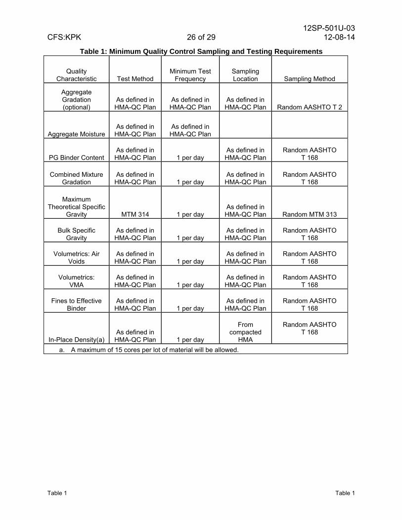
Table 1: Minimum Quality Control Sampling and Testing Requirements
Quality Characteristic Test Method
Minimum Test Frequency
Sampling Location Sampling Method
Aggregate Gradation (optional)
As defined in HMA-QC Plan
As defined in HMA-QC Plan
As defined in HMA-QC Plan Random AASHTO T 2
Aggregate Moisture As defined in HMA-QC Plan
As defined in HMA-QC Plan
PG Binder Content As defined in HMA-QC Plan 1 per day
As defined in HMA-QC Plan
Random AASHTO T 168
Combined Mixture Gradation
As defined in HMA-QC Plan 1 per day
As defined in HMA-QC Plan
Random AASHTO T 168
Maximum Theoretical Specific
Gravity MTM 314 1 per day As defined in HMA-QC Plan Random MTM 313
Bulk Specific Gravity
As defined in HMA-QC Plan 1 per day
As defined in HMA-QC Plan
Random AASHTO T 168
Volumetrics: Air Voids
As defined in HMA-QC Plan 1 per day
As defined in HMA-QC Plan
Random AASHTO T 168
Volumetrics: VMA
As defined in HMA-QC Plan 1 per day
As defined in HMA-QC Plan
Random AASHTO T 168
Fines to Effective Binder
As defined in HMA-QC Plan 1 per day
As defined in HMA-QC Plan
Random AASHTO T 168
In-Place Density(a) As defined in HMA-QC Plan 1 per day
From compacted
HMA
Random AASHTO T 168
a. A maximum of 15 cores per lot of material will be allowed.
12SP-501U-03 CFS:KPK 27 of 29 12-08-14
Table 2 Table 2
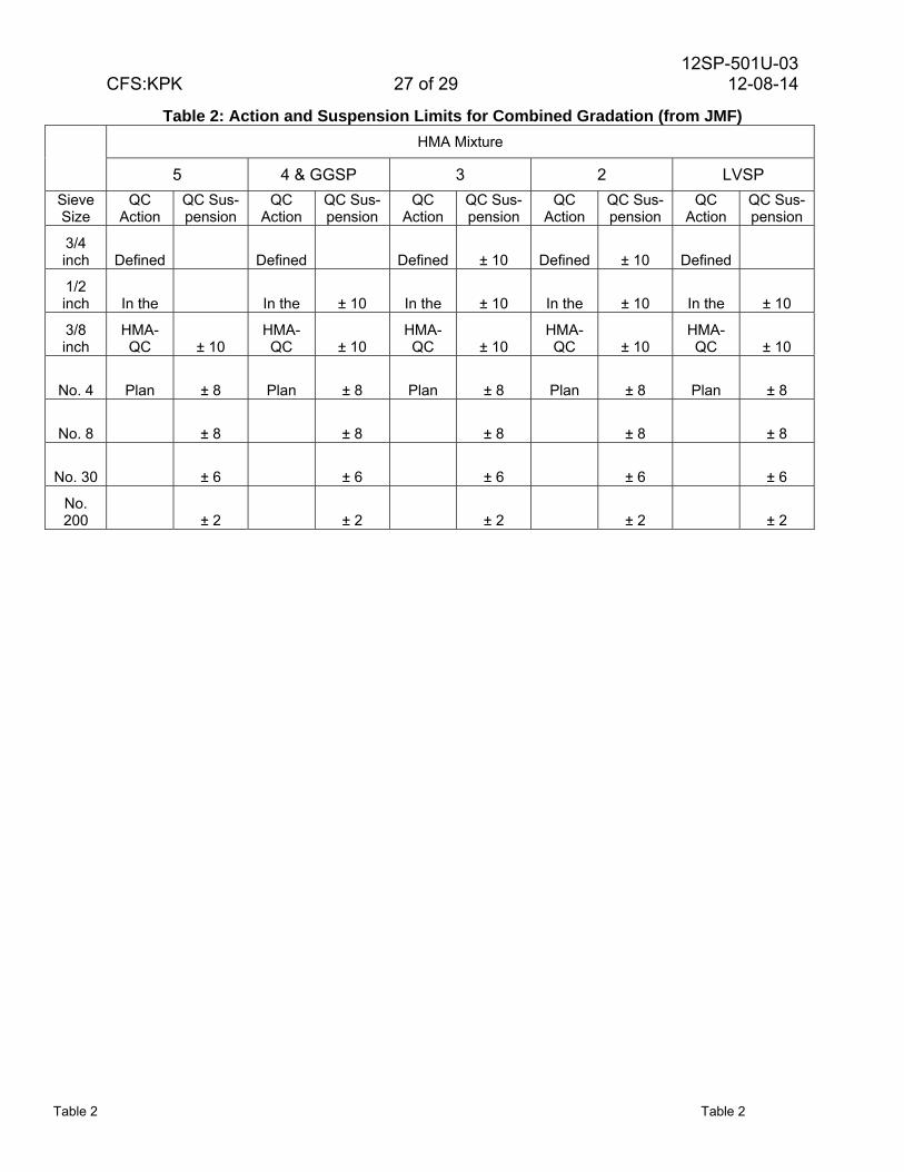
Table 2: Action and Suspension Limits for Combined Gradation (from JMF) HMA Mixture
5 4 & GGSP 3 2 LVSP
Sieve Size
QC Action
QC Sus- pension
QC Action
QC Sus- pension
QC Action
QC Sus- pension
QC Action
QC Sus- pension
QC Action
QC Sus- pension
3/4 inch Defined Defined Defined ± 10 Defined ± 10 Defined
1/2 inch In the In the ± 10 In the ± 10 In the ± 10 In the ± 10
3/8 inch
HMA-QC ± 10
HMA-QC ± 10
HMA-QC ± 10
HMA-QC ± 10
HMA-QC ± 10
No. 4 Plan ± 8 Plan ± 8 Plan ± 8 Plan ± 8 Plan ± 8
No. 8 ± 8 ± 8 ± 8 ± 8 ± 8
No. 30 ± 6 ± 6 ± 6 ± 6 ± 6
No. 200 ± 2 ± 2 ± 2 ± 2 ± 2
12SP-501U-03 CFS:KPK 28 of 29 12-08-14
Table 3 Table 3
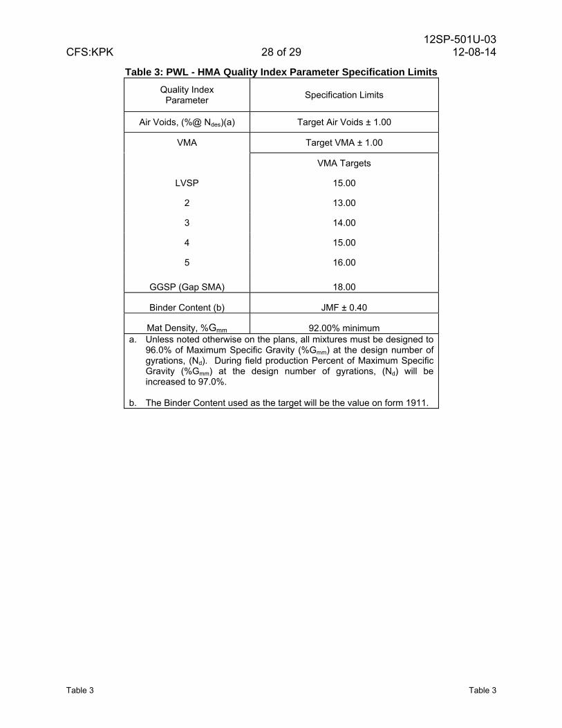
Table 3: PWL - HMA Quality Index Parameter Specification Limits
Quality Index Parameter
Specification Limits
Air Voids, (%@ Ndes)(a) Target Air Voids ± 1.00
VMA Target VMA ± 1.00
VMA Targets
LVSP 15.00
2 13.00
3 14.00
4 15.00
5 16.00
GGSP (Gap SMA) 18.00
Binder Content (b) JMF ± 0.40
Mat Density, %Gmm 92.00% minimum a. Unless noted otherwise on the plans, all mixtures must be designed to
96.0% of Maximum Specific Gravity (%Gmm) at the design number of gyrations, (Nd). During field production Percent of Maximum Specific Gravity (%Gmm) at the design number of gyrations, (Nd) will be increased to 97.0%.
b. The Binder Content used as the target will be the value on form 1911.
12SP-501U-03 CFS:KPK 29 of 29 12-08-14
Table 4 Table 4
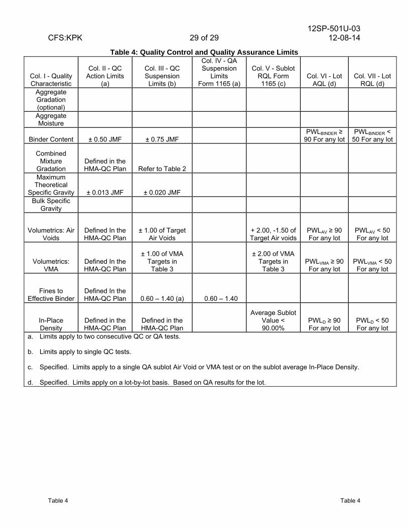
Table 4: Quality Control and Quality Assurance Limits
Col. I - Quality Characteristic
Col. II - QC Action Limits
(a)
Col. III - QC Suspension
Limits (b)
Col. IV - QA Suspension
Limits Form 1165 (a)
Col. V - Sublot RQL Form 1165 (c)
Col. VI - Lot AQL (d)
Col. VII - Lot RQL (d)
Aggregate Gradation (optional) Aggregate Moisture
Binder Content ± 0.50 JMF ± 0.75 JMF PWLBINDER ≥
90 For any lotPWLBINDER <
50 For any lot
Combined Mixture
Gradation Defined in the HMA-QC Plan Refer to Table 2
Maximum Theoretical
Specific Gravity ± 0.013 JMF ± 0.020 JMF Bulk Specific
Gravity
Volumetrics: Air Voids
Defined In the HMA-QC Plan
± 1.00 of Target Air Voids
+ 2.00, -1.50 of Target Air voids
PWLAV ≥ 90 For any lot
PWLAV < 50 For any lot
Volumetrics: VMA
Defined In the HMA-QC Plan
± 1.00 of VMA Targets in
Table 3
± 2.00 of VMA Targets in
Table 3 PWLVMA ≥ 90 For any lot
PWLVMA < 50 For any lot
Fines to Effective Binder
Defined In the HMA-QC Plan 0.60 – 1.40 (a) 0.60 – 1.40
In-Place Density
Defined in the HMA-QC Plan
Defined in the HMA-QC Plan
Average Sublot Value < 90.00%
PWLD ≥ 90 For any lot
PWLD < 50 For any lot
a. Limits apply to two consecutive QC or QA tests. b. Limits apply to single QC tests. c. Specified. Limits apply to a single QA sublot Air Void or VMA test or on the sublot average In-Place Density. d. Specified. Limits apply on a lot-by-lot basis. Based on QA results for the lot.