1204-019 offshore update 1-2012_bc_lowres_595x780
TRANSCRIPT

Phot
o: x
x
offshoreupdate
Low risks in the high north?
X-streamForensic investigation
news From Dnv to the oFFshore inDustry no 01 2012

2 | oFFshore uPDate NO. 1 2012
cONteNts
offshore update
361104X-streamLow risks in the high north?Forensic investigation
Published by Dnv maritime and oil & gas, market communications
editorial committee: Blaine collins, Director, Divisional staff, Division americas magne a. røe, editor Lisbeth aamodt, Production Design and layout: coormedia.com 1204-019
Front cover: ship of the year – North Sea Giant. see page 24 Photo: north sea shipping
Please direct any enquiries to [email protected]
online edition of offshore update: www.dnv.com/offshoreupdate
Dnv (Det norske veritas as) no-1322 høvik, norway tel: +47 67 57 99 00 © Det norske veritas as www.dnv.com
Forensic engineering and Failure investigations enhance saFe operation and preserve assets .......................... 4
low risks in the high north? ......................................................... 11
standardising arctic challenges ............................................... 14
subsea 7 buoyancy supported risers For petrobras ........... 18
take control From well to terminal with silverpipe .... 22
introducing the ship oF the year – the North Sea GiaNt .........................................................................24
soFtware standard gains momentum with new drilling rigs .................................................................................. 28
a plug-in solution ................................................................................ 30
new dnv drive results in updated rule book For selF-elevating units ................................................................... 32
barrier management For oFFshore saFety .............................. 34
taking deepwater pipelines to the X-stream ......................... 36
energy eFFiciency For osvs ................................................................ 40
barents 2020 conclusive summary ................................................ 44
wellstream awarded dnv’s local content certiFication For brazilian operations .................................. 46
deepwater drives the development oF new technology.................................................................................... 48
west aFrican gas pipeline .................................................................. 49
mooring systems in deepwater Fields ........................................ 50
hushing underwater noise ............................................................. 54
maintenance oF mobile oFFshore units and Floating structures – it’s only getting better ........ 56
dnv houston shows soFtware integrity ................................. 58
synergi looks to asia and the americas ................................... 60
pertamina: going For “world class” by 2014 ............................ 62
observations oF onshore pipeline regulatory trends... 64
oil spill risk management ................................................................ 66
making sems – enhancing oFFshore saFety in north america .................................................................................. 68
dnv acquires vattenFall shares in stri ................................... 70
›› ›› ››
offshore update

oFFshore uPDate NO. 1 2012 | 3
eDitOrial
we have been reminded several times over the last few years that major accidents happen and that external events can have a significant impact on our lives, our industry and our business. the question is not whether we are exposed to risks and uncertainty, but how we can manage them, and how we can maximise our opportunities and rewards
while minimising our exposure.
managing risk is now a buzzword, and boards and managers everywhere are looking for effective risk management solutions. risk management should be an integral part of an organisation, something that influences behaviours and decisions every day. and the efficiency of risk management methods should be measured by well-defined parameters to enable us to learn what is working and stop what does not lead to improve-ments.
both the offshore oil and gas industry and maritime industry have demonstrated significant improvements in occu-pational safety, safe and healthy working condi-tions for men and women, over the last decade. that job will never end but, overall, we can say that occupational safety is
improving and that cur-rent best practices are effective.
attention to major acci-dents, such as the preven-tion of fires, explosions, navigational errors, col-lisions and similar acci-dents, is a different story. the earlier risk manage-ment thinking was that reducing the frequency of accidents would lead to a positive correlation to a reduction in the more severe accidents. how ever, we have no indications that this has happened.
managing risk is the core of dnv’s business and we are continuously working to stay at the fore-front of the development of methodology and prac-tices, in order to be even more effective in prevent-ing accidents and mitigat-ing their consequences.
today, barrier manage-ment has been identified as an effective way of pre-
venting major accidents. the methodology consid-ers scenarios and threats that may lead to major accidents. then, for each threat, barriers – techni-cal, physical, operational procedures, manage-ment and decision mak-ing – are developed and implanted to remove the threat, prevent it from occurring or mitigate its consequences. bar-rier management is also well-suited for managing both the immediate, or short-term, and long-term consequences of an accident. indeed, barriers have critical functions to safeguard life, property and the environment.
however, analyses of most major accidents show that barriers have been in place but that the failure of these barriers has led to accidents or failed to control the con-sequences. why? barriers are not typically moni-
tored during operations, operators are not aware of the significance of barri-ers or decisions are made without regard to barrier status. barrier manage-ment includes addressing the deterioration of a barrier over time, usually in operating practices, and a rapid response in order to maintain barri-ers, including decisions to shut down if a barrier is not functioning.
as we move forward, let’s remember that a key element of successful risk management is moni-toring changing threat and hazard conditions, especially the status of the barrier designed to control them to prevent accidents.
the risk picture in our industry continues to increase in complex-ity and we need to take a giant leap, make a big step change, in how we manage process risk.
rethiNkiNg risk MaNageMeNt FOr OFFshOre saFety
elisabeth h. tørstadchief operating officer, Division americas [email protected]
LEAD
THEPOWER
TO
Phot
o: s
tock
byte
/get
ty im
ages

4 | oFFshore uPDate NO. 1 2012
FOreNsic eNgiNeeriNg aND Failure iNvestigatiONs
Forensic engineering and failure investigations enhance safe
operation and preserve assetsForensic engineering is the investigation of materials, products, structures or
components that fail or do not operate or function as intended, causing personal injury, damage to property or the environment, or a loss of productivity.
teXt: NEIL G. THOMPSON, dnv
Forensic and failure investigations also deal with retracing processes and proce-dures leading up to accidents involving the operation of vehicles, equipment, machin-ery and other assets. the term forensics is applied most commonly in legal cases, although the same cause analyses apply more generally to failure investigations. the purpose of a forensic engineering investigation is to determine the cause or causes of failure (1) with a view to improv-ing the performance or life of a compo-nent, (2) to prevent a similar failure and promote lessons learned and safe operat-ing practices, or (3) to establish the root cause of the failure.
the following are important in the field of forensic engineering: (1) the process of investigating and collecting data related to the materials, products, structures or com-ponents that failed and (2) the documen-tation of the records, evidence and docu-ments received. this involves inspections, collecting evidence, measurements, devel-oping models, obtaining exemplar prod-ucts and conducting tests and simulations.
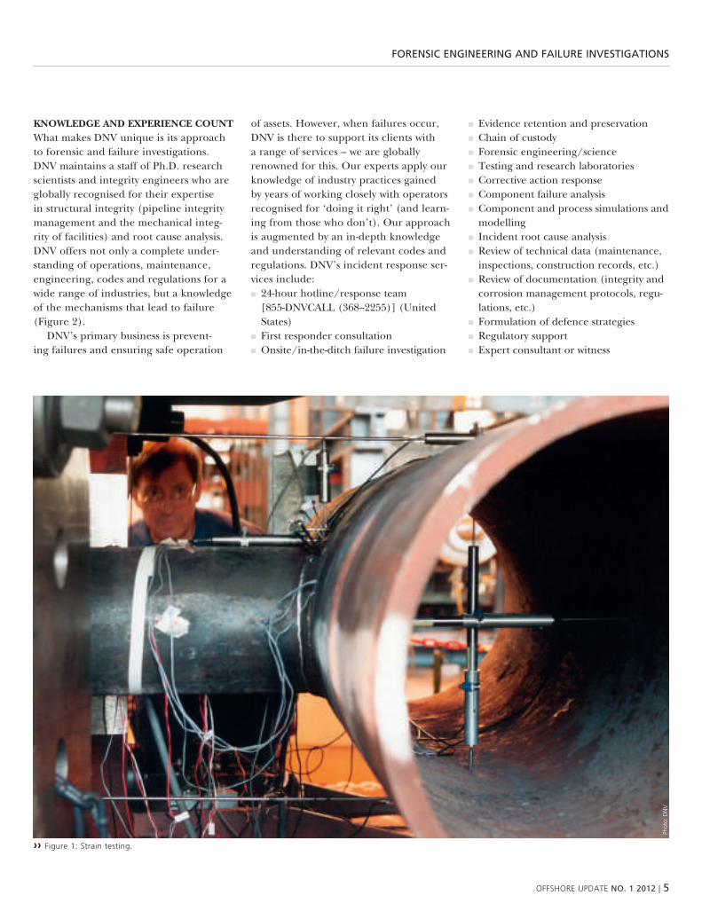
THE DNV TEaM dnv is one of the few firms to combine engineering with state-of-the art research and testing (Figure 1). dnv maintains four primary laboratory facilities throughout the world to serve the needs of its customers. these are located
in høvik and bergen in norway, in dublin, ohio, usa, and in singapore.
dnv’s researchers and scientists at these facilities work closely with the dnv engi-neering staff to provide customers with engineering solutions based on funda-mental science, as well as testing solutions balanced by sound engineering practice. dnv has laboratory and engineering expertise in the fields of mechanical, structural, materials, corrosion, chemi-cal and metallurgical engineering. the company serves the oil and gas, maritime, power utility, alternative cleaner energy production, onshore and offshore pipe-line, refinery and deepwater applications industries.
dnv’s renowned scientists have exten-sive experience in designing laboratory tests and selecting critical variables that permit the accurate simulation of field conditions. dnv’s staff not only stay on the cutting edge of the latest practices and technologies, but in many cases also drive cutting-edge practices through their mul-titude of testing activities, research pro-grammes and joint industry programmes. dnv has the ability to conduct component testing that utilises state-of-the-art analyti-cal techniques, including laser scanning; scanning electron, optical and three-dimensional microscopy; energy dispersive,
x-ray and ramon spectroscopy; and many others.
testing and research includes:■■ technology qualification■■ Full-scale testing of components and systems
■■ process simulations■■ process development and changes■■ materials selection■■ chemical treatment needs■■ corrosion mitigation and monitoring■■ coating specifications and selection■■ elastomer selection■■ Fracture mechanics and fatigue■■ multiphase flow testing
dnv’s ability to perform model simula-tions is critical to many forensic and fail-ure investigations. these include finite ele-ment (or boundary condition) analysis for mechanical, structural, thermal, corrosion and cathodic protection, soil movement, and flow model simulations. specialised models have been developed for corrosion damage growth predictions, creep life pre-dictions, predictions of critical pressure for failure of pressure vessels, etc.
dnv performs failure and forensic investigations worldwide, using its diverse laboratory network and over 300 offices in 100 countries. dnv has a staff of more than 9,000, a high percentage of whom are scientists, researchers and engineers.
oFFshore uPDate NO. 1 2012 | 5
FOreNsic eNgiNeeriNg aND Failure iNvestigatiONs
KNOwLEDGE aND ExPErIENcE cOuNT what makes dnv unique is its approach to forensic and failure investigations. dnv maintains a staff of ph.d. research scientists and integrity engineers who are globally recognised for their expertise in structural integrity (pipeline integrity management and the mechanical integ-rity of facilities) and root cause analysis. dnv offers not only a complete under-standing of operations, maintenance, engineering, codes and regulations for a wide range of industries, but a knowledge of the mechanisms that lead to failure (Figure 2).
dnv’s primary business is prevent-ing failures and ensuring safe operation
of assets. however, when failures occur, dnv is there to support its clients with a range of services – we are globally renowned for this. our experts apply our knowledge of industry practices gained by years of working closely with operators recognised for ‘doing it right’ (and learn-ing from those who don’t). our approach is augmented by an in-depth knowledge and understanding of relevant codes and regulations. dnv’s incident response ser-vices include:■■ 24-hour hotline/response team [855-dnvcall (368–2255)] (united states)
■■ First responder consultation■■ onsite/in-the-ditch failure investigation
■■ evidence retention and preservation■■ chain of custody■■ Forensic engineering/science■■ testing and research laboratories■■ corrective action response■■ component failure analysis■■ component and process simulations and modelling
■■ incident root cause analysis■■ review of technical data (maintenance, inspections, construction records, etc.)
■■ review of documentation (integrity and corrosion management protocols, regu-lations, etc.)
■■ Formulation of defence strategies■■ regulatory support■■ expert consultant or witness
›› Figure 1: strain testing.
Phot
o: D
nv

6 | oFFshore uPDate NO. 1 2012
FOreNsic eNgiNeeriNg aND Failure iNvestigatiONs
›› Figure 2: Pipeline failure inspection.
Phot
o: D
nv

oFFshore uPDate NO. 1 2012 | 7
FOreNsic eNgiNeeriNg aND Failure iNvestigatiONs
rOOT cauSE aNaLySIS Forensic and failure analyses can take many forms and levels of activities. many failure investi-gations focus on the immediate failure cause; i.e., for metals, the metallurgical or technical aspects of the failure. laboratory tests are performed to determine whether or not a material meets the applicable mechanical and chemical specifications. metallurgical analyses are performed to determine whether the failure was associ-ated with an overload, fatigue vibrations, corrosion, or any of a number of other causes. going further, basic causes such as operational issues can be examined, e.g., a review of the technical literature, such as corrosion and integrity management protocols, is performed to determine what aspects of the operations and maintenance contributed to the failure.
a true “root cause” analysis takes the investigation one step further. the root cause analysis considers the management decisions that were made, or not made, and that contributed to the failure. by tracing the cause of the failure back to failures of management systems or pro-cesses, it becomes more likely that similar failures will be prevented from occurring in the future. this improves performance by avoiding lost production time and repair or clean-up costs, provides a safer
environment for employees and the pub-lic (for assets such as pipelines), and pre-vents costly environmental damage (for assets dealing with hazardous liquid and gases).
a good root cause analysis is depend-ent on a complete and accurate basic and intermediate cause analysis. understand-ing the chain of technical events and management decisions leading up to a failure allows one to “reverse engineer” and reconsider decisions and operational processes. ideally this leads to recommen-dations that are implemented by manage-ment. there are many tools that can be used to assist in the root cause investiga-tion. some of these tools are commonly used project or programme management techniques. some of the tools are highly specialised, and designed to focus specifi-cally on root cause analysis and failure investigations.
general tools include various statistical analysis techniques, charts and diagrams. most engineers and managers are familiar with histograms, scatter charts, tree dia-grams and fault tree analyses. many are familiar with “cause-and-effect” diagrams (also known as “fishbone” or “ishikawa” diagrams), which can be invaluable in clarifying the different components or processes that may have contributed to a
failure. an example is given in Figure 3. the best root cause analysis tools force one to consider aspects of the failure that may not be obvious to the casual observer.
dnv has developed an approach that is specifically designed to perform root cause analysis. this approach is the systematic causation analysis technique (scat), which is a structured application of the loss causation model (lcm). the lcm is based on the concept that a loss of man-agement control can ultimately lead to an accident/failure. the loss of control leads to a basic cause of a failure, which leads to an immediate cause of a failure. by tracing the appropriate chain of events, one can identify and correct the loss of control that contributed to a given failure.
the scat approach begins with a col-lection of all the available evidence. this will include the findings of the failure analysis, as well as interviews with key personnel involved in the incident and a review of the applicable documentation. the evidence is used to develop a timeline of the events that led to the failure. key events may include: lack of inspection, inadequate response to inspections, lack of control of operating parameters, operating outside of the design envelope, etc. most industrial accidents/failures can be attrib-uted to a chain of events. it is important
Materials Measurements Environment
Accident
Personnel Methods Equipment
training
errors
management
operations
inspections
procedures
valves
pumps
welding
welds
alloys
steels
CP
NDE
pressure
product
soil
temperature
Management Review
Monitoring and measurement
Implementation and operation
Planning
Strategy and Policy
ContinualImprovement
›› Figure 3: a “cause-and-effect”, or ishikawa, diagram. ›› Figure 4: continuous improvement loop.

8 | oFFshore uPDate NO. 1 2012
FOreNsic eNgiNeeriNg aND Failure iNvestigatiONs
to understand how and why each event occurred and how it led to the next event in the chain.
Following the development of a time-line of key events is an analysis of barriers. barriers are any components or systems that are put in place to prevent failures. physical barriers include pressure and temperature control systems and other similar barriers. more “abstract” barriers to consider are the training of personnel, communication procedures and quality assurance protocols. it is the failure of these barriers that leads to the events that make up the chain preceding the failure. each one of the events in the chain must be analysed separately to understand how and why the barriers in place to prevent them failed. For each one of the events, one must consider the immediate, basic and management control contributions. the failure only occurred because all of the barriers failed.
once the analysis has identified the true root cause of the failure, it becomes possible to make recommendations to prevent future failures. as most failures are the result of the failure of several bar-riers or several human errors, it is likely that several corrections could be imple-mented into the operational procedures or management systems to correct the root cause. this may include the re-train-ing of staff or additional review of designs and procedures. new safety systems or operational processes can be implement-ed as necessary. the prevention of future failures is the real value of a root cause analysis.
LESSONS LEarNED dnv has the ability to follow up its forensic investigations with operational and management reviews to implement the lessons learned. dnv has developed the international safety rating system 8th edition (isrs8) as an accumu-lation of best practice experience in safety and sustainability management. isrs8 has been developed over 30 years and is regularly updated to reflect changes and improvements in safety management. the 8th edition of isrs was issued in 2009 and
includes elements of process safety man-agement as well as updates to reflect the changes in international standards such as ohsas 18001:2007, iso 9001:2008 and the global reporting initiative 2006.
isrs8 is designed to ensure the health of industrial processes, drive continu-ous improvement and ensure effective risk management. isrs8 takes strategy and policy, planning, implementation and operation, monitoring and measure-ment, management review, and continual improvement and combines these efforts into one procedure that can be used to manage any industrial process. a visual representation of the isrs process is shown in Figure 4.
caSE STuDy – BLOwOuT PrEVENTEr FrOM THE DEEPwaTEr HOrIZON DIS-aSTEr on the evening of 20 april 2010, while drilling at the macondo prospect, control of the well was lost, allowing hydro-carbons to enter the drilling riser and reach the deepwater horizon, resulting in explosions and subsequent fires. the fires continued to burn for approximately 36 hours. the rig sank on 22 april 2010. From shortly before the explosions until 20 may 2010, when all rov interven-tion ceased, several efforts were made to seal the well. the well was permanently plugged with cement on 19 september 2010.
a Joint investigation team (Jit) con-sisting of members of the departments of the interior (doi) and homeland security (dhs) was charged with investigating the explosion, loss of life and blowout associ-ated with the deepwater horizon drilling rig failure. as part of this overall investiga-tion, dnv was retained to undertake a forensic evaluation of the blowout preven-ter (bop) stack, its components and asso-ciated equipment used by the deepwater horizon drilling operation.
in the event of a loss of well control, various components of the bop stack function in an attempt to seal the well and contain the blowout. the most important of these components is the blind shear ram (bsr). the focus of the forensic
investigation was on determining the cause of the failure of the bsr to cut the pipe and seal the well.
dnv was uniquely positioned to assem-ble a team of experts with all the necessary competencies to complete the project; including expertise in large project foren-sic investigations, deep water drilling, bop operation and design, materials science, mechanical engineering, electronic sys-tems, laboratory testing, and structural and mechanical system modelling. the dnv team was led by the dublin, ohio materi-als and corrosion technology centre, with staffing support from the dublin, ohio’s asset risk management group, dnv’s hou-ston’s energy solutions group and product verification and inspection group, and dnv høvik, norway’s energy solutions group.
the visibility of this forensic investiga-tion was understandably high. through-out the investigation, several us federal agencies were involved and had repre-sentatives on site; including the bureau of ocean energy management regulation and enforcement (boemre), us coast guard, nasa, Federal bureau of investiga-tion, environmental protection agency, department of Justice, department of the interior and chemical safety board. in addition, a technical working group (advi-sory capacity only) consisting of technical representatives of other interested parties was established and legal representatives of interested parties were permitted on site. all the parties were present to observe or advise, but all final decisions were made by the dnv team and approved by the Jit. the investigation was conducted in a us coast guard dock on the nasa michoud Facility in new orleans, la and at other facilities on the nasa base. as an indica-tion of the project size, 400 persons signed non-disclosure agreements as a part of this project over the 13-month duration.
using a fault tree analysis and scat timeline to narrow the possibilities, the investigation included the function test-ing of the hydraulic systems, control systems and individual components of the bop, including the bsr, casing shear
oFFshore uPDate NO. 1 2012 | 9
FOreNsic eNgiNeeriNg aND Failure iNvestigatiONs
rams, three variable bore rams (vbr), of which the lower one was configured as a test ram, and annulars on the lower marine riser package (lmrp). the most significant findings involved the drill string pieces removed from the bop and the riser adjacent to the bop. as in any investigation, the direction of the investi-gation must be governed by the evidence available. although, when the investiga-tion started, many thought that the bsr did not function, the drill pipe and rams told a different story. the investigation indicated that the bsr had functioned, resulting in the pipe being at least partial-ly sheared, but the drill pipe was located off-centre in the wellbore and a portion of the pipe was caught in the faces of the bsr ram blocks outside the cutting surfaces. this prevented the bsr from fully closing and sealing the wellbore and permitted the flow to continue and the subsequent erosion to enlarge the effec-tive flow path area.
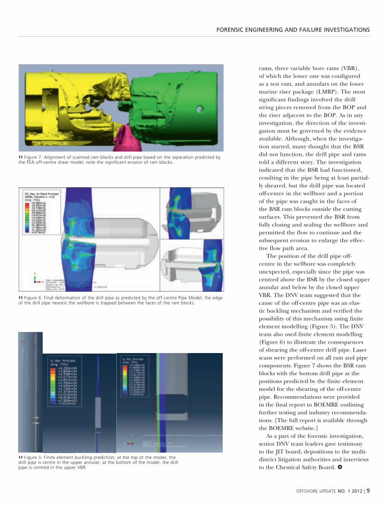
the position of the drill pipe off-centre in the wellbore was completely unexpected, especially since the pipe was centred above the bsr by the closed upper annular and below by the closed upper vbr. the dnv team suggested that the cause of the off-centre pipe was an elas-tic buckling mechanism and verified the possibility of this mechanism using finite element modelling (Figure 5). the dnv team also used finite element modelling (Figure 6) to illustrate the consequences of shearing the off-centre drill pipe. laser scans were performed on all ram and pipe components. Figure 7 shows the bsr ram blocks with the bottom drill pipe at the positions predicted by the finite element model for the shearing of the off-centre pipe. recommendations were provided in the final report to boemre outlining further testing and industry recommenda-tions. [the full report is available through the boemre website.]
as a part of the forensic investigation, senior dnv team leaders gave testimony to the Jit board, depositions to the multi-district litigation authorities and interviews to the chemical safety board.
›› Figure 6: Final deformation of the drill pipe as predicted by the off-centre Pipe model; the edge of the drill pipe nearest the wellbore is trapped between the faces of the ram blocks.
›› Figure 7: alignment of scanned ram blocks and drill pipe based on the separation predicted by the Fea off-centre shear model; note the significant erosion of ram blocks.
›› Figure 5: Finite element buckling prediction; at the top of the model, the drill pipe is centre in the upper annular; at the bottom of the model, the drill pipe is centred in the upper vBr.

10 | oFFshore uPDate NO. 1 2012
arctic OperatiON

oFFshore uPDate NO. 1 2012 | 11
arctic OperatiON
low risks in the high north?
major oil and gas accidents in the past few decades have forced significant improvements in technology, procedures and regulations. “now, when seeking opportunities in the arctic areas we must ensure the same level of risk as in the north sea,” emphasises knut Ørbeck-nilssen,
Dnv coo Division norway, russia and Finland.
teXt: SVEIN INGE LEIrGuLEN, dnv
oil and gas producing countries have experienced several catastrophic accidents in the past 30 years. alexander l. kiel-land in norway, piper alpha in the uk, montara in australia and deepwater horizon in the us have all claimed many lives or caused significant oil spills.
mr Ørbeck-nilssen explains that another common char-acteristic with all these tragedies is that they were completely unexpected. however, they have forced the development of improved procedures, standards and technologies. on the regulatory side, responsibilities have become clearer and new governmental safety agencies have been established.
“offshore safety has never been so high on the public agenda as in the past year. the industry is debating how to improve technologies and safety solutions, and authorities in both the us and the eu are developing stricter requirements for oil and gas operations. there is no doubt that the rules of the game will change with more focus on offshore safety, environmental protection and risk assessments,” he predicts.
rISK MaNaGEMENT ENHaNcES SaFETy “the use of a risk management approach is vital to increase safety. we should not confuse the risk of a certain event taking place with only the consequences it may result in. that is not taking into account the likelihood for the event to occur. this approach, the so-called ‘worst case scenario’ will lead to many decisions without a sound factual basis.
“this is not what risk is about. risk management is about increasing safety by analyzing what and where something can go wrong, minimising the probability for it to occur and
Phot
o: D
amir
cve
toje
vic

12 | oFFshore uPDate NO. 1 2012
›› as the industry moves north into the arctic, and seen in the light of risk management, both policy makers and the industry must agree on an acceptable risk level. as a minimum we should maintain the same risk level as in the north sea,” says knut Ørbeck-nilssen, Dnv coo Division norway, russia and Finland.
Phot
o: D
amir
cve
toje
vic
arctic OperatiON
ensuring that you can reduce its conse-quences,” he clarifies.
an oil and gas operator who embraces this approach within its management system will be able to enhance and man-age safety levels, continuously. authorities that base their regulations on a risk based approach will also have a pragmatic tool that enables them to decide on an accept-able level of risk for their countries to harvest resources. this also provides the basis for regulations that allow for technol-ogy development and new and better solu-tions. risk analyses will further provide a common interface for discussions between stakeholders, for example regarding a decision of whether or not to allow an industrial activity.
“this is indeed how many companies and countries, such as norway and the uk, have managed their oil and gas operations for many years. here, both regulations and operations are based on risk management, and the responsibility falls on the operator to obtain a certain safety level,” says mr Ørbeck-nilssen.
MaNaGING Icy rISKS 20% of the world’s undiscovered resources may be found in the arctic regions. he points out that exploration has already started in the harsh environments found in greenland, shtokman and the barents sea, with more to come.
“in these locations, achieving safe operations is more demanding than in
for example the north sea, where oil and gas has been produced since the 1970s in some of the world’s most challenging con-ditions. in the high north the conditions are much, much tougher. extremely low temperatures and long periods of darkness create a demanding working environment for personnel, but it also affects the mate-rial properties and operation of equip-ment,” he explains.
snow, slush, fog and icing can reduce the functionality and availability of safety barriers. and closely linked to this is the question of how emergency preparedness and oil spill recovery can be provided in case of an accident.
“how do you remove oil from ice, and how do you evacuate 100 people in a

oFFshore uPDate NO. 1 2012 | 13
arctic OperatiON
–50°c snowstorm 200 km from the shore with limited infrastructure in remote loca-tions?” he asks.
“these are just a few examples of the safety challenges we must face in the years to come, but i know that much research and development is already in process,” mr Ørbeck-nilssen points out.
INTErNaTIONaL cOOPEraTION he emphasises another important issue, which is international cooperation.
“all five arctic coastal states must work together to implement the same under-standing, standards and regulations with regards to offshore safety. a great example of cooperation is the barents 2020 project between russia and norway. since 2006,
experts from both countries have worked closely together in order to learn, develop and harmonise rules for safety in the bar-ents region. this was initially a bilateral initiative, but it is now developing into a significant pan-arctic project,” he states.
mr Ørbeck-nilssen believes that as the industry moves north into the arctic, and seen in the light of risk management, both policy makers and the industry must agree on an acceptable risk level. as a minimum we should maintain the same risk level as in the north sea.
he explains that, since the consequenc-es in these sensitive areas will be much higher in case of an accident, the empha-sis must be on developing solutions which reduce the probability of undesired events.
“Further, to minimise the consequences of an accident, the industry and the regu-lators must work together to find appropri-ate mitigation measures in order to meet the agreed risk level,” he underlines.
“we recommend that the five arctic states agree on common regulations, and the industry must develop technologies and standards adapted to the harsh arctic conditions. i see this more as an opportu-nity than a threat, as long as we manage the new risks in a systematic, unified and transparent manner,” concludes knut Ørbeck-nilssen.
›› in the high north the conditions are tough. extremely low temperatures and long periods of darkness create a demanding working environment for personnel, but it also affects the material properties and operation of equipment.
Phot
o: D
amir
cve
toje
vic
MajOr acciDeNts siNce 1980
aLeXanDer L. kieLLanDthe collapse of the alexander L. kielland rig in 1980 is still fresh in the minds of the international oil and gas industry and particularly in the norwegian community. a bracing on one of the legs broke, probably due to fatigue, and the unit had no redundancy against this eventuality. shortly after, the leg was lost, causing a rapid list of 30–35 degrees. after twenty minutes the rig turned upside down completely. nobody had foreseen this accident which caused 121 lives.
PiPer aLPhaeight years later, on the uk continental shelf, 167 lives were lost in the Piper alpha disaster, making this the worst offshore accident ever experienced. an explosion was caused by gas released and ignited by hot gas turbine casings or frictional sparks.
montara in 2009, an oil and gas leak and subsequent slick took place in the montara oil field in the timor sea, off the northern coast of western australia. Lasting for 74 days, it was one of australia’s worst oil accidents.
DeePwater horiZonthe Deepwater horizon accident happened on april 20, 2010 when the control of the macondo well was lost resulting in explosions and fires on the drilling rig. it was the largest oil spill in us history, and in comparison to the exxon valdez’ 500,000 barrels spill, the macondo well released five million barrels into the gulf of mexico.

14 | oFFshore uPDate NO. 1 2012
staNDarDisiNg arctic challeNges
standardising arctic challengesstandardising arctic challengesas the ice melts, the arctic region is becoming more accessible. with an estimated 22
per cent of the world’s undiscovered resources lying beyond the arctic circle, the energy industry is looking north. trade routes are also opening up and will allow a shorter passage between certain areas. the nature of this environment – untouched, remote and wild – has made it as appealing as it is precarious over the past hundred years. Per olav moslet, Dnv’s
programme director for arctic technology, discusses arctic safety issues in this article.
teXt: SVEIN INGE LEIrGuLEN, dnv

oFFshore uPDate NO. 1 2012 | 15
staNDarDisiNg arctic challeNges
Phot
o: D
nv

16 | oFFshore uPDate NO. 1 2012
staNDarDisiNg arctic challeNges
Fram – a three-masted schooner powered by a steam engine – was launched in 1892. she was reputed to be the strongest wooden ship ever built and the one that sailed closest to both poles. guided by dnv classification rules, the vessel was designed and built by the famous ship constructor colin archer from larvik in norway to withstand the extreme effects of high ice pressure on the hull on its way to the north pole.
Fram’s capabilities in ice were dem-onstrated on her first expedition – to the north pole with the scientist Fridtjof nansen. where other ships had been smashed to pieces by ice pressure, Fram’s innovative hull design raised her above the ice. the vessel returned home to nor-way in 1896 as a great success. two years later, Fram was heading for the antarctic, carrying roald amundsen and his team on their way to becoming the first men to reach the south pole. once again, she withstood the strains and hardships of the polar oceans, successfully carrying the expedition to the antarctic and back.
IcE cLaSS NOTaTIONS not surprisingly, given our norwegian roots, dnv has a long history of working with ships and structures in ice. the first requirements for additional ice strengthening were set in
1881. in the years since the Fram expedi-tions, dnv has become the leading clas-sification society for vessels working in ice and is continuously increasing the market share of both its maritime and offshore cold climate classification activities.
this position is largely due to our independence, experience of harsh envi-ronments and, for more than a century, unchanging commitment to “safeguarding life, property and the environment”. we help the industry to manage the risks in the arctic and antarctic regions.
through its extensive experience, dnv has an in-depth understanding of the chal-lenges of operating in the polar regions. our rules set standards for safe operations in cold climates. ice class and winterization rules are tailored to specific operational needs in different ice conditions. the winterization notations help ensure that the crew and essential systems can operate in freezing temperatures and icing condi-tions. obviously, the correct application of such notations increases operability and reduces the risk of damage.
HarSH OFFSHOrE wOrKING ENVI-rONMENT arctic environmental condi-tions will have a strong influence on the working environment and technical safety of offshore operations in the barents sea. therefore, design requirements need to be considered in order to ensure that offshore units meet the facility integrity and operability requirements under these conditions.
the general design philosophy must be that technical safety and the quality of the working environment on facilities in the barents sea are to be maintained at the same level as on other facilities not exposed to arctic environmental
conditions. to meet the arctic’s work-ing environment challenges, specific requirements are set as to system and equipment design, construction and operations that will influence the overall safety level.
all systems, equipment and areas of a facility where the arctic environment may impair safety, functionality or operability need to be evaluated with respect to the working environment. a systematic process for evaluating and selecting solutions is required to ensure that the risk level is as low as reasonably practicable. Finally, the evalua-tion process should be risk-reduction driven.
preference must be given to selecting permanent, technical solutions rather than temporary, operational or procedural solu-tions. it is important to select solutions that improve safety and the quality of the working environment without introducing adverse side effects.
the main objective is to provide ade-quate protection for personnel so as to ensure their health, safety, performance and decision-making under the expected arctic environmental conditions. the installation design should minimise expo-sure to spray, wind, cold and the accumu-lation of ice and snow. in order to provide such protection, the main principle is to enclose or shield working areas from the elements wherever practicable. areas that are not fully or partially protected and where snow and ice may accumulate should be provided with anti-icing or de-icing arrangements as appropriate.
designers should especially consider the danger to personnel from ice falling from structures such as cranes and derricks. the layout design can minimise this hazard by arranging work areas away from structures that are likely to accumulate snow and ice,
“marine icing is a concern for several statoil projects and there is a need for development of tools for icing predictions. statoil will continue to address icing related issues and contribute to improved knowledge on the subject.”
kenneth eik, statoil
›› Per olav moslet, Programme Director, arctic technology.
Phot
o: D
nv

oFFshore uPDate NO. 1 2012 | 17
MvD 250 µm MvD 2000 µm
15.6
–21.
6 m
13–1
5.6
m9.
8–13
m0–
9.8
mstaNDarDisiNg arctic challeNges
a substantial part of the world’s undiscovered hydrocarbon reservoirs are expected to be found in the arctic. exploration and production drilling in the arctic is challenging due to the long distance to the existing infrastructure, 24-hour darkness and low temperatures, but drilling is a necessary step in order to extract the hydrocarbons.
the Marice prOjectobjective:to improve the physical understanding of marine icing (‘sea spray icing’) and to translate this into numerical models and science-based guidelines for design and operations. to develop real-time icing severity maps for forecasting purposes and to assist in vessel routing to minimise icing effects, with emphasis on the waters north of norway and russia.
activities:ice accretion-rate measurements have been conducted for two seasons on svalbard, using custom-built equipment to estimate the rate of ice formation in natural conditions. computational fluid dynamic (cFD) simulations show the areas of moving vessels most susceptible to sea spray and spray-derived icing. measurements are also being conducted on rig-supply vessels operating in arctic waters to assist and help verify the simulations.
Participants:Dnv, the norwegian university of science and technology (ntnu), statoil and the norwegian research council.
‹‹ Figure showing the marine-icing simulation results from the marice project.
or protecting work areas with roofing that can withstand the impact of falling ice.
cOLD aND wIND cHILL ExPOSurE arc-tic offshore operations expose workers to cold, windy and wet conditions. working in a cold environment can cause several adverse effects on human performance and health, from discomfort, strain and decreased performance, to cold-related injuries and diseases. due to the adverse impact of cold on human health and per-formance, as well as on work productivity, quality and safety, operators need a com-prehensive strategy of risk assessment and management practices for offshore work in cold environments such as the arctic.
the main philosophy for reducing exposure to the cold is to keep outdoor operations to a bare minimum. as a guide, this means limiting the time that an individual is exposed to a wind chill factor of –10°c or colder. Frequently manned areas should be sheltered without exceeding the allowable explosion risks. strategies and practical tools for assessing
and managing cold risks in the workplace may be found in iso standard 15743 and 15265. these standards support good occupational health and safety, and are applicable to offshore work in the arctic. they include:■■ models and methods for cold-risk assess-ment and management,
■■ a checklist for identifying cold-related problems at work,
■■ models and methods for individual cold protection, and
■■ guidelines on how to apply thermal standards and other validated scientific methods when assessing cold-related risks.
DEaLING wITH HaZarDOuS MarINE IcING interest in shipping and oil & gas activities in the arctic has been growing during the past decade. in parallel, this increases the need for the proper predic-tion of sea spray icing.
experience from activities in cold weather regions indicates that ice accre-tion on vessels and offshore structures
must be taken into account to provide safe and efficient operations. marine icing (or “sea spray icing”), the focus of the marice project, causes hazardous situ-ations due to e.g. slippery ladders and gangways, frozen and blocked escape and rescue routes and equipment as well as frozen process equipment and valves, and is expected to reduce operating efficiency or mission performance. accidents may lead to injuries or even loss of lives, environmental damage and damage to assets. For smaller vessels, superstructure icing can even result in the loss of the ship, typically through capsizing.
1.0+00
7.1e-01
5.0e-01
3.5e-01
2.5e-01
1.8e-01
1.3e-01
8.9e-02
6.3e-02
4.5e-02
3.2e-02
2.2e-02
1.6e-02
1.1e-02
7.9e-03
5.6e-03
4.0e-03
2.8e-03
2.0e-03
1.4e-03
1.0e-03

18 | oFFshore uPDate NO. 1 2012
subsea 7’s buOyaNcy suppOrteD risers
subsea 7 buoyancy supported risers for petrobrasBased on an interview with victor Bomfim, vP subsea 7,
conducted by sergio garcia, Dnv
subsea 7 is a seabed-to-surface engineer-ing, construction and services contractor to the offshore energy industry worldwide. subsea 7 provides integrated services and has a proven track record in delivering complex projects in deep water and chal-lenging environments. in this interview subsea 7 victor snabaitis bomfim senior vice president for brazil describes the cur-rent project for petrobras.
What has motivated this riser system concept to be developed?
the buoyancy supported risers (bsr) concept was developed as a result of a design competition launched by petrobras in 2009 to select a solution for what was requested as a de-coupled riser system for use in their deepwater pre- salt fields offshore brazil. the bsr is a system which is de-coupled from the movements of the Fpsos on the surface.
one motivation behind this type of concept was the requirement for special type of materials needed to deal with the unique characteristics of the products flowing through the pipes. some of the production wells on the pre-salt fields have high co2 and h2s content. because of that, the standard coupled, flexible system is not an option since materials for those characteristics are still being developed / qualified. therefore, petrobras had to go for a steel solution, but even the carbon steel solution in itself is not applicable due
to the corrosive nature of the fluids, so the solution was to go with some form of corrosion resistant alloy (cra) pipes. the concept was a result of the need for the type of material that is required to with-stand the high pressure coming from the well and water depth which is beyond 2100 meters, added to the corrosiveness of the fluid being transported.
the other main reason was petrobras’ intent to de-couple the construction of the subsea system from the construction of the wells and the Fpso. this way the riser sys-tem can be installed without the wells and the Fpso being completed. the concept allows the construction and installation of the subsea system to be decoupled from the standard field development installation process where, the subsea system normally is in the critical path in order to connect the wells to the Fpso with both ends present.
in response to the design competition, subsea 7 presented the development of the bsr solution. the concept of the bsr is not exactly a new concept in the indus-try. other operators have thought about this in the past, but petrobras has devel-oped the concept further. back in 2004, subsea 7 had been contracted by petro-bras to develop some procedures for the installations of the risers of this buoy and to undertake the feasibility study of the concept. based on our previous knowledge about this concept we believed that this
solution would be an ideal answer to the challenges that have been presented from petrobras to the industry.
What are the main elements of this Guará – Lula Ne riser System concept?
the concept is very simple but at the same time it has it complexities. it is sim-ple because you have a buoy in the subsur-face moored at around 250 meters below the sea level, at which depth the effects of the surface, like the waves, do not inter-fere. therefore, since flexible lines are already qualified for this depth, they’ll be connected from the Fpso to the buoy on a very stable condition. the deepest portion will connect the buoy to the wells through the cra steel catenary risers.
however, although the concept is de-coupled, you need to analyze the system as a whole. in other words, the Fpso’s move-ments, how the Fpso is affected by the mooring, how the movements of the Fpso are transmitted to the flexibles, then to the buoys, the current, and finally the ris-ers itself down to the seabed. the concept in itself is simple, but the interactions are very complex.
Which elements would you highlight as techno-logical breakthroughs?
First one, in which dnv has been involved, is the qualification of using the reeling method for installing mechani-cally lined pipe. we have an exclusive

oFFshore uPDate NO. 1 2012 | 19
subsea 7’s buOyaNcy suppOrteD risers
›› victor Bomfim, vP subsea 7
Phot
o: g
isel
la F
ranc
isca
, D
nv

20 | oFFshore uPDate NO. 1 2012
subsea 7’s buOyaNcy suppOrteD risers
agreement with a german company called butting, who produce mechanically line pipe called bubi® in which a cra liner is installed inside a standard carbon steel pipe to give the necessary corrosion resistant properties. we have undertaken a joint programme that has been support-ed by dnv to get the type approval for the offshore reeling application. we have been through a number of qualifications and tri-als in order to prove that this mechanically lined pipe is fit for this type of offshore application. this is a programme that was concluded and type approved in 2010 and we are using this technology in this pro-ject. this was a major achievement because the reel-lay method for this application is
very cost effective. being able to get this technology type approved was a major and important step for the success of this project.
another important technology that resulted as part of this process is what we call the angular connection module, which is the system for the connection of flexible lines to the risers that are coming from the seabed. the risers that are con-nected to the buoy have a certain angle in order to connect to the flexible jumper, which is going to connect the buoy to the Fpso. this angular connection module is something that has been specially devel-oped for this project and was qualified by petrobras following the guidelines as
recommended on dnv rp-a203 quali-fication of new technology. we have designed the system to make sure it would get the qualification process with petrobras approved. this qualification was conclud-ed a few months ago. this was the second important innovation point.
the third technical breakthrough is the procedure for the actual installation of the buoy on site at 250 meters below the surface. the buoy has a number of compartments that need to be flooded or filled with air or nitrogen in a controlled manner, such that it can be lowered into position and provide the buoyancy that is needed for that situation. the whole procedure and methodology for actually
›› the Bsr system – Buoy, steel catenary risers, Flexible Jumpers and tethers ›› a general view of the Buoyancy supported risers system
illus
trat
ion:
sub
sea
7
illus
trat
ion:
sub
sea
7

oFFshore uPDate NO. 1 2012 | 21
subsea 7’s buOyaNcy suppOrteD risers
installing the buoy in the position is also a unique and very innovative solution.
there is also another important innova-tive element in this project which is the tension system to connect the buoy to the tendons. in terms of concept, the buoy is not actually moored with a spread moor-ing system but it is like a submerged ten-sion leg platform. in order to control the tension subsea 7 designed what we call the “top tensioning system”. the tendons are wire ropes with a length of chain con-nected to the jacking system attached to the buoy. in this specific case the develop-ment of this ip has been done together with petrobras.
What is the project’s present stage? the design engineering phase is almost
complete. Fabrication of almost all the
components has started, and we are now developing the detail engineering instal-lation phase. we aim to have all the main components fabricated by the end of the year to start installation in late 2012.
how do you see DNV’s contribution to this project?
dnv has been on board since day one and is the verification body for the pro-ject. the importance of the dnv team presence locally in our office in rio inte-grated with the subsea 7 team to expedite the whole engineering approvals, as well as in other locations, has been vital for achieving the present status. subsea 7 will use dnv rp-a203 qualification of new technology as part of bringing its new technology to market. the whole involve-ment of dnv on the type approval of the
mechanically lined pipe, following dnv recommended practice, gave confidence to the stakeholders on this project. in sum-mary, dnv’s role as an independent veri-fier is an important part of the project’s success.
With both companies’ high value and invest-ments on r&D, which other innovative projects would you highlight on the horizon for the part-nership Subsea 7 and DNV?
talking about brazil specifically, this is a small first step in a long journey. it’s up to us to make sure that the technology which will be used in developing these huge reserves in very deep waters will be there available to be applied.
›› a detailed view of the Buoy
illus
trat
ion:
sub
sea
7
22 | oFFshore uPDate NO. 1 2012
silverpipe
take control from well to terminal with silverpipe
reduce unplanned shutdowns with a timely response to integrity issues. keep track of history as well as the current situation. optimise your inspection programme using the results of
risk-based inspection studies. take control, from well to terminal, with silverPipe.
teXt: KaIa MEaNS
MaNaGE, TracK aND acT without a clear overview of the integrity of pipelines and components and the risk of failure, management cannot ensure appropriate action is taken to ensure safe operations and follow up the status as work progress-es. silverpipe is dnv software’s integrity and risk management software, tailored to help operators continuously improve pipe-line safety and reliability, thus reducing downtime and extending operational life.
silverpipe manages the integrity and risk of the entire infrastructure of onshore pipelines and facilities, and is equally fit for long haul lines, in-field installations and regional distribution networks. silver-pipe is used by customers for the safe and cost-efficient operation of complete oil infrastructures from wells to downstream terminals and gas transportation networks.
the built-in capabilities for managing company integrity strategies and detailed integrity plans give integrity managers a powerful tool to stay on top of the situa-tion and to ensure that inspections and assessments are carried out as planned.
our customers report increased effi-ciency, as silverpipe delivers one system that provides an overview of the whole integrity cycle, supporting all activities that manage integrity and risk. a total configu-rable package supports company best prac-tices and gives managers a situation map and risk log that includes company-specific work processes. gis and inspection data-base integrations ensure seamless access to existing pipeline information.
rISK DaSHBOarD our risk dashboard provides an unrivalled overview of your asset during its life cycle, including docu-menting risk and the decision-making process, control of integrity plans, and systems that allow managers to ensure that projects deliver as planned. it offers full traceability of integrity management events and decisions, streamlining controlling and improvement activities from well to terminal.
the robust and documented interfaces between life cycle data management and integrity assessment tools ensure the con-sistency and quality of calculations and make integrity decisions documented and auditable. dnv’s assessment tools are based on 50 years of experience in deliv-ering software to the industry, and cover calculations for strength assessment, code compliance and qra as well as calculators for risk-based inspection planning (rbi) for components and tank systems.
silverpipe can be interfaced with dnv’s powerful and world leading phast suite of software for dispersion modelling, hazard analysis and qra. with more than 1,000 customers globally, phast is the most well-validated and functionally comprehensive risk analysis software available for manag-ing the risks associated with hazardous installations.
silverpipe adheres to industry-accepted codes such as dnv, asme, nace and api. the overall risk is aggregated, reported and used to optimise long-term integrity plans. separate assessment of pipelines,
components and hotspots using qualitative and semi-quantitative approaches is the basis for risk aggregation.
PHaSED IMPLEMENTaTION OF cOM-PrEHENSIVE SySTEMS it is often a challenge for companies to get started with comprehensive risk and integrity management systems. it certainly requires careful planning, a phased implementa-tion plan and trained staff. through a modular software approach, powerful data import mechanisms, interfaces with exist-ing company systems such as erp, gis and document systems, as well as by offering a skilled integrity management staff, dnv helps companies implement best integrity practices and ensure sustainable and reli-able integrity processes.
it is essential to document and track risk decisions. silverpipe uses the risk matrix and best engineering concepts to enforce company policies and uniform working. through pre-defined report tem-plates, the periodical reports to authorities and other stakeholders are produced con-sistently and cost-effectively.
silverpipe closes the loop between assessment, inspection and mitigation with full traceability of integrity management events and decisions. the simplicity of its graphics, including colour-coded real-time status, keeps operators continuously informed.
life cycle management solutions help operators manage information, identify risks and make qualified decisions using

oFFshore uPDate NO. 1 2012 | 23
silverpipe
configurable and scalable engineering soft-ware, accessing all relevant asset data, both current and historical.
MEETING NEEDS a full report on the use of silverpipe for the integrity man-agement of a pipeline system (oil export pipelines, oil storage tanks and satellite platforms) in the north sea has pro-vided valuable customer feedback. the report showed that silverpipe improved
corrosion management through internal corrosion monitoring and mitigations. the interface between the disciplines covering the operation of topside facili-ties, wells and the pipeline system was also a focus area. the performed assessment study concluded that the main threat to the pipelines was internal corrosion. the only way to regain confidence in the integrity status was through in-line inspec-tions, which were subsequently performed
for the multiphase and water injection pipelines. a capacity check was conducted together with a remaining life assess-ment in order to ensure the further safe operation of the pipelines. a strategy for how to control corrosion was established and both long-term and annual plans for internal inspection and monitoring were prepared.
›› silverPipe delivers one system that covers the whole integrity cycle, supporting all activities that manage integrity and risk.
reDuce DOwNtiMe, exteND OperatiONal liFesilverPipe 6.1 brings new and enhanced capabilities to our customers worldwide:• PODSandAPDMcompliance• ConfigurableGISintegration• Revisionmanagement• Richdataviewerwithalignedviewsofuser-
selectable profiles• Richsurveyresultsmoduleconfigurableto
customers’ import formats and result types (naming conventions)
• Enhancedsemi-quantitativeriskmodule• VerificationreportsforDNVandASMEcode
checks and pressure containment calculations• Enhanceddatavalidation• Corrosionanderosionandremaininglife
calculations
Dnv software is a leading provider of risk-management software to the energy, process and maritime industries – offering design, engineering, strength assessment, risk and reliability, Qhse and asset integrity management solutions. Dnv software is part of Dnv and almost 300 Dnv offices in 100 countries enable us to be close to our customers and share best practices and quality standards worldwide.Ph
oto:
get
ty im
ages
24 | oFFshore uPDate NO. 1 2012
the ship OF the year
introducing the ship of the year – the North Sea Giant
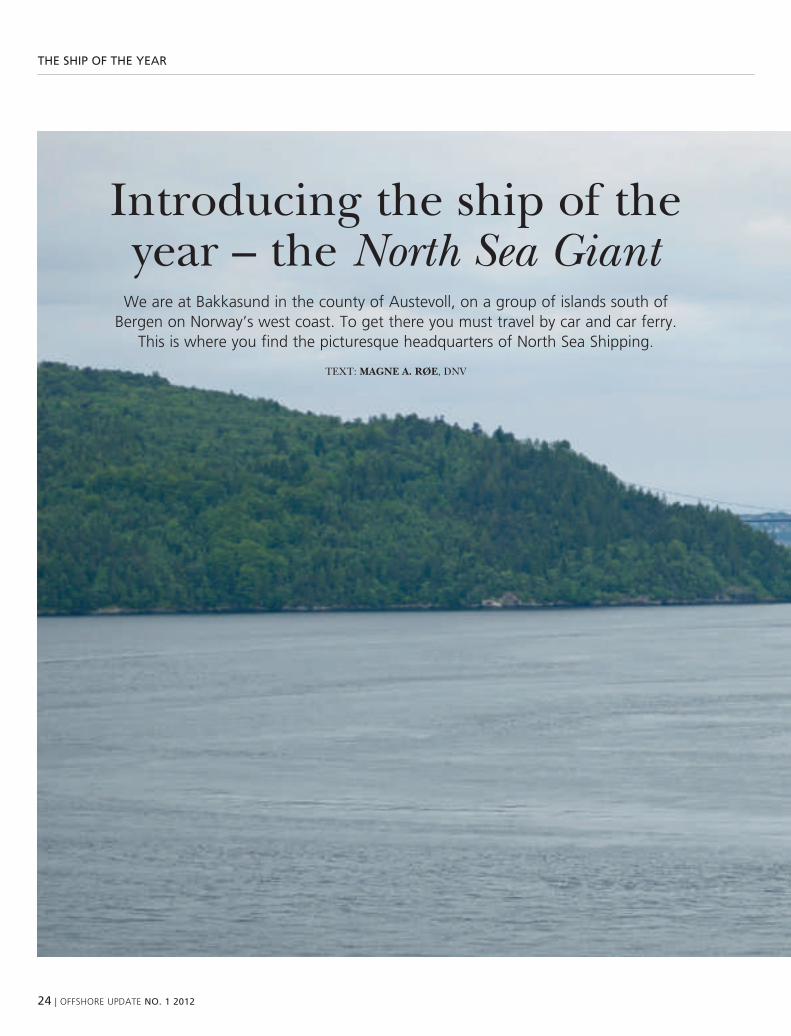
we are at Bakkasund in the county of austevoll, on a group of islands south of Bergen on norway’s west coast. to get there you must travel by car and car ferry.
this is where you find the picturesque headquarters of north sea shipping.
teXt: MaGNE a. røE, dnv

oFFshore uPDate NO. 1 2012 | 25
the ship OF the year
Phot
o: n
orth
sea
shi
ppin
g
26 | oFFshore uPDate NO. 1 2012
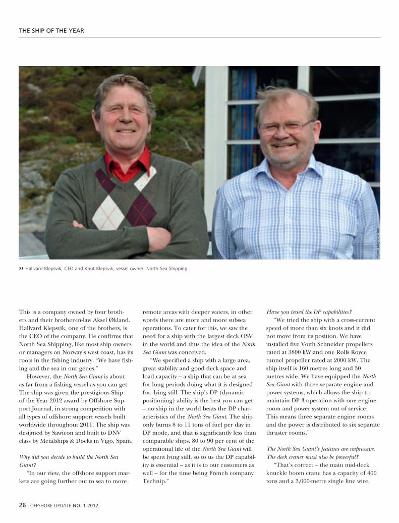
›› hallvard klepsvik, ceo and knut klepsvik, vessel owner, north sea shipping.
Phot
o: m
agne
a.
røe
the ship OF the year
this is a company owned by four broth-ers and their brother-in-law aksel Økland. hallvard klepsvik, one of the brothers, is the ceo of the company. he confirms that north sea shipping, like most ship owners or managers on norway’s west coast, has its roots in the fishing industry. “we have fish-ing and the sea in our genes.”
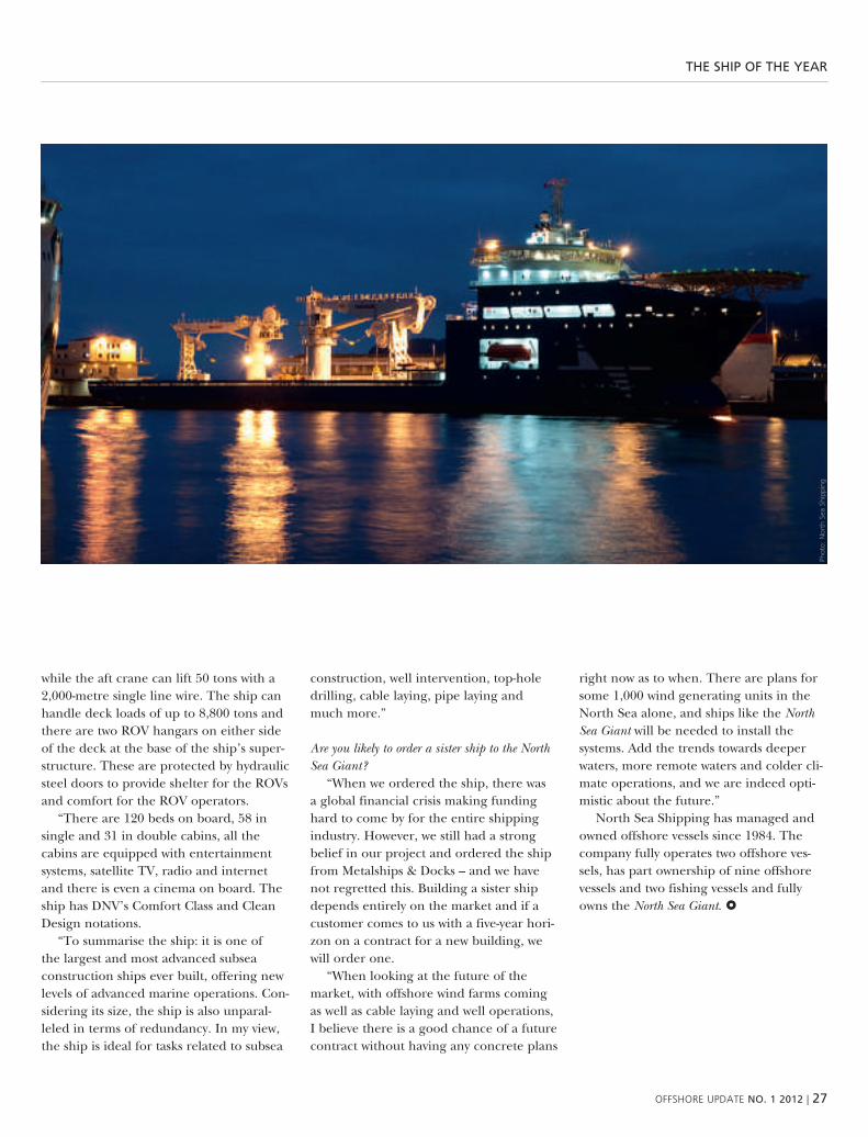
however, the North Sea Giant is about as far from a fishing vessel as you can get. the ship was given the prestigious ship of the year 2012 award by offshore sup-port Journal, in strong competition with all types of offshore support vessels built worldwide throughout 2011. the ship was designed by sawicon and built to dnv class by metalships & docks in vigo, spain.
Why did you decide to build the North Sea Giant?
“in our view, the offshore support mar-kets are going further out to sea to more
remote areas with deeper waters, in other words there are more and more subsea operations. to cater for this, we saw the need for a ship with the largest deck osv in the world and thus the idea of the North Sea Giant was conceived.
“we specified a ship with a large area, great stability and good deck space and load capacity – a ship that can be at sea for long periods doing what it is designed for: lying still. the ship’s dp (dynamic positioning) ability is the best you can get – no ship in the world beats the dp char-acteristics of the North Sea Giant. the ship only burns 8 to 11 tons of fuel per day in dp mode, and that is significantly less than comparable ships. 80 to 90 per cent of the operational life of the North Sea Giant will be spent lying still, so to us the dp capabil-ity is essential – as it is to our customers as well – for the time being French company technip.”
have you tested the DP capabilities?“we tried the ship with a cross-current
speed of more than six knots and it did not move from its position. we have installed five voith schneider propellers rated at 3800 kw and one rolls royce tunnel propeller rated at 2000 kw. the ship itself is 160 metres long and 30 metres wide. we have equipped the North Sea Giant with three separate engine and power systems, which allows the ship to maintain dp 3 operation with one engine room and power system out of service. this means three separate engine rooms and the power is distributed to six separate thruster rooms.”
the North Sea Giant’s features are impressive. the deck cranes must also be powerful?
“that’s correct – the main mid-deck knuckle boom crane has a capacity of 400 tons and a 3,000-metre single line wire,
oFFshore uPDate NO. 1 2012 | 27
the ship OF the year
while the aft crane can lift 50 tons with a 2,000-metre single line wire. the ship can handle deck loads of up to 8,800 tons and there are two rov hangars on either side of the deck at the base of the ship’s super-structure. these are protected by hydraulic steel doors to provide shelter for the rovs and comfort for the rov operators.
“there are 120 beds on board, 58 in single and 31 in double cabins, all the cabins are equipped with entertainment systems, satellite tv, radio and internet and there is even a cinema on board. the ship has dnv’s comfort class and clean design notations.
“to summarise the ship: it is one of the largest and most advanced subsea construction ships ever built, offering new levels of advanced marine operations. con-sidering its size, the ship is also unparal-leled in terms of redundancy. in my view, the ship is ideal for tasks related to subsea
construction, well intervention, top-hole drilling, cable laying, pipe laying and much more.”
are you likely to order a sister ship to the North Sea Giant?
“when we ordered the ship, there was a global financial crisis making funding hard to come by for the entire shipping industry. however, we still had a strong belief in our project and ordered the ship from metalships & docks – and we have not regretted this. building a sister ship depends entirely on the market and if a customer comes to us with a five-year hori-zon on a contract for a new building, we will order one.
“when looking at the future of the market, with offshore wind farms coming as well as cable laying and well operations, i believe there is a good chance of a future contract without having any concrete plans
right now as to when. there are plans for some 1,000 wind generating units in the north sea alone, and ships like the North Sea Giant will be needed to install the systems. add the trends towards deeper waters, more remote waters and colder cli-mate operations, and we are indeed opti-mistic about the future.”
north sea shipping has managed and owned offshore vessels since 1984. the company fully operates two offshore ves-sels, has part ownership of nine offshore vessels and two fishing vessels and fully owns the North Sea Giant.
Phot
o: n
orth
sea
shi
ppin
g

28 | oFFshore uPDate NO. 1 2012
sOFtware staNDarD gaiNs MOMeNtuM with New DrilliNg rigs
software standard gains momentum with new drilling rigs
songa offshore’s latest north sea drilling rig will be built to Dnv’s standard for managing complex, software dependent systems and, as the first of a comprehensive
newbuilding program, and the first full-blown application for Dnv, the project is expected to set a new industry standard in software management.
teXt: wENDy LaurSEN
songa offshore of norway has specified dnv’s isds standard for integrated soft-ware dependent systems for the first of their seventh generation semi-submersible drilling rigs being built specifically as stat-oil’s new work horses for the norwegian continental shelf. although pilot tested on a number of other projects, it will be the first full-blown application of the standard to a newbuild and the project participants, as well as other key industry stakeholders, are preparing for its accept-ance as a new industry standard.
the isds notation establishes a meth-odology that aims to minimise software integration errors and delays in projects that involves complex, software dependent systems. the notation includes the devel-opment of quality assurance processes that will last throughout the drilling unit’s operational lifetime.
statoil has much to gain from a suc-cessful implementation of isds as the company has plans for several new drilling units tailor made to work on the mature fields of the norwegian continental shelf. two category d units designed to perform drilling, completion and heavy interven-tion activities 20 per cent more efficiently than the existing fleet have already been ordered by stat oil from songa offshore and the order for dsme in korea includes the option for two more. scheduled for delivery in 2014, they will be able to oper-ate at water depths of 100–500 metres and drill wells down to 8,500 metres. while
tailor-made for mid-water segments on the norwegian continental shelf, the design is also suitable for other regions and can easily be converted for work in deep water, high pressure high temperature operations and arctic operations.
as charterer and operator, stat oil sees significant benefits from applying isds including reduced risk of delays during construction and improved control over reliability, availability, maintainability and safety once the units are operational. “soft-ware integrity is important for us as we embark on this project,” says Jan magne gilje, technical coordinator for cat-d in statoil. “statoil is working hard to utilise new technology to increase recovery and extend the life of the fields on the norwe-gian continental shelf. we are applying innovative thinking on everything about the cat-d midwater rigs. this requires solid change management processes and isds will help us do that.”
statoil believes the key to maintaining today’s production level on the norwe-gian continental shelf towards 2020 is improved recovery from existing fields and fast and efficient development of new fields. Fit for purpose rigs and utilisation of technology will be important measures to increase recovery and extend the life of the fields. isds supports these ambitions starting with the first cat-d deliveries and potentially also to other rigs. software reli-ability is clearly and consciously an impor-tant part of such a project.
dnv has begun the familiarisation process with project participants. steven durham, songa’s cat-d project director is on location in korea. “i can see that isds is a good concept,” he says. “software control and management of change have been problematic in the past so we openly accept this initiative. we want it to work. right now, here in korea, we are all think-ing through what it means for us individu-ally as well as at a company level.”
the new avenues for communication and control that isds establishes between owner, yard and vendors will be developed during engineering, construction and ultimately commissioning. “when we get all the third party equipment on site in the yard, then we will see the real results,” says mr durham. “aside from the potential for software glitch-es to delay a project, they can ultimately be dangerous to those on board. therefore, we all want isds to be successful.”
For dsme, it means working with many suppliers to meet the isds requirements and, as the first yard to be involved in such a project, they hope to gain a competitive advantage from its success. sverre Fjereide, project controls manager for dsme, is cau-tiously optimistic that it will ease commis-sioning problems and reduce after-delivery support efforts. “we are the guinea pigs,” he says. “we hope to get a better focus on engineering and testing requirements that can be specifically applied to software as this has been less than ideal in the past. isds will not solve all problems but it will

oFFshore uPDate NO. 1 2012 | 29
sOFtware staNDarD gaiNs MOMeNtuM with New DrilliNg rigs
hopefully improve the situ-ation. if we can get a 50 per cent improvement in software-related delays during commis-sioning, then it will be a big success especially given the complex nature of such pro-jects and their time limits.”
For Jon Fredrik lehn-pedersen, kongsberg’s gen-eral manager for drilling and offshore automation, the interface problems that arise between suppliers during commissioning can be time consuming, expensive and can introduce an element of risk that should be avoided with isds. working with isds means that the necessary inter-faces are clearly documented and approved by class early on and they then form the basis for all design, engineering and factory acceptance work. too often re-working is required during commissioning when it becomes apparent that the parties involved have not put the required effort into the ini-tial specifications, he says, and when problems occur, there is always a lot of discussion about who is responsible.
although, isds may mean that kongsberg puts extra resources into the early phase of the project, at least until they gain more experience with dnv’s requirements, mr lehn-pedersen believes the system is com-mon-sense and practical and follows the same principles that they have developed in-house over time. since 2008, kongsberg has been delivering dynamic positioning, power management and integrated auto-mation systems to about 20 latest genera-tion drilling units each year. mr lehn-ped-ersen believes isds would have been very useful over this time. “it is definitely time for this to happen now,” he says.
while existing class rules work to ensure a drilling unit or ship is safe, they are not
intended to ensure operability and effi-ciency, especially for non-safety critical sys-tems. however, software related downtime can be a problem throughout the life of a drilling unit as most software is designed with a three-year lifecycle compared to the 20–25 year design life of the hardware.
isds places particular focus on soft-ware service providers, but roles and responsibilities are defined for all parties involved. “with the diagnostic functional-ity and remote access that is incorporated into drilling units now, it is really impor-tant that software integrity is maintained throughout the operational lifetime of the
unit and that any weaknesses are not propagated throughout a fleet from one delivery to the next,” says rolf benjamin Johansen, dnv’s project direc-tor for systems and software reliability.
dnv applies methodologies that have proven effective in the aerospace, telecommunica-tions, defence and automotive industries. their experience with isds from previous pro-jects with seadrill, dolphin drilling, odfjell, total and stat oil indicates that applying the isds class notation can easily save usd 6–20 million by addressing potential problems early in a project and thereby avoiding the delays caused by the need to re-work software.
the notation provides a framework with industry-wide reach for systematically assur-ing the quality and perfor-mance of software-dependent systems and many key stake-holders are already gaining confidence with it. some companies that are yet to be directly involved in other pro-jects have already approached dnv and asked them to assess their delivery practices for compliance.
“what is unique about the dnv isds standard is that we look at sys-tem integration as a whole, for the entire drilling rig or ship, and we also make sure our approach is flexible enough to fit in with and augment current good industry practices,” says mr Johansen. these charac-teristics and the foothold they have already gained in the industry places dnv in a position of leadership. “dnv believes that all new drilling units and major modifica-tions should apply isds. it will create value for all parties involved, and even applied retrospectively to operational units, it improves the ongoing safety and reliability of drilling operations.”
›› isDs ensures that software integrity is maintained throughout the lifetime.
Phot
o: D
nv
›› Dnv has developed a standard for integrated software Dependent systems, isDs.
Phot
o: D
nv

30 | oFFshore uPDate NO. 1 2012
a plug-iN sOlutiON
a plug-in solutionthe offshore wind arena is currently flooded with a number of un resolved questions.
what’s the best way to bring electricity ashore from wind farms far off the coast? should there be a cable running from each wind farm to the shore, or should we create an
offshore electricity grid, to simply plug in the production plants? is it better to use ac or Dc? on a frequent basis, governments, project developers and network operators ask
Dnv kema energy & sustainability to investigate and answer these questions.
teXt: MarjOLEIN rOGGEN, dnv kema
all of the countries fringing the north sea currently have ambitious plans for the realization of offshore wind farms. by 2020, for example, the netherlands intens to have 6,000 mw of capacity installed at sea, while germany and the united kingdom are aiming for 15,000 mw and about 30,000 mw, respectively. not only will the erection of so many off-shore turbines be an enormous operation, but getting the electricity they produce to shore is quite an undertaking.
INDIVIDuaL caBLES as the number of offshore installations grows, the idea of connecting each of them to the onshore grid by its own cable begins to look less attractive. there are drawbacks for project developers, for the authorities and for the environment. For every cable project, a new permit procedure has to be followed, and realization is an expensive and time-consuming undertaking that puts the continuity of supply at risk. in most cases, the creation of a sea-to-shore connection is also outside the core competence of the developer or proprietor. add to the mix the considerable energy losses associ-ated with long-range transmission and the need to have cable crossings along the coastline at numerous points, and it’s easy to see why alternative solutions are being examined.
MaKING THE cONNEcTION as early as 2003, the dutch ministry of economic affairs asked kema and others to inves-tigate the potential technical, licensing, regulatory, and financial hurdles that must be addressed before connecting 6,000 mw of offshore capacity to the onshore grid. “it’s not only about the connections them-selves, but also about the need to upgrade the infrastructure on land,” explains dnv kema’s Frits verheij, “Feeding power into the grid from offshore wind farms will result in additional loads on the existing substations and cables.”
“with the dutch government’s sustain-ability ambitions in mind, we began mak-ing practical preparations for an offshore electricity grid in 2008,” recalls lex hart-man of dutch transmission system opera-tor tennet. “the spatial planning for bringing cables ashore at the dutch coast has already started.” in contrast to the way things work elsewhere, obtaining the nec-essary planning license in the netherlands is by no means a formality. the developer of a wind farm is the one responsible for connecting the facility to the onshore grid. “making tennet responsible for an off-shore electrical infrastructure would have various economic benefits, including lower capital costs and purchasing advantages,” affirms hartman. “coordinated grid development planning would also reduce
the risk of over-investment or under-investment, and would be in line with the way the european market is developing. it would also pave the way for the possible long-term creation of a shared renewable energy ‘supergrid’ spanning the north sea.”
cONSIDErING THE aLTErNaTIVES kema was initially asked by tennet to identify and analyze the technical and policy developments associated with the attainment of an offshore grid connecting various european countries. later, we also came up with a range of technical options and a decision-making methodology toselect the most suitable solution, taking account of various parameters, such asdis-tance to the coast.
“For this study, we worked on the basis of offshore wind farm ‘building blocks’, each with a collective capacity of 1000 mw. we then assessed what the best alternatives were. First, if the wind farms were sited 30 kilometers from the onshore connection point, and then if they were 120 kilometers away,” recounts verheij. “we considered energy losses, reliability, environmental impact, security of supply, market matu-rity, vulnerability of the technology to future developments, flexibility and degree of innovation. and, everything was set off against the cost. For each offshore distance

oFFshore uPDate NO. 1 2012 | 31
a plug-iN sOlutiON
option, we further developed the three-most preferred alternatives.”
PrEFErrED cONNEcTION the study indicated that if the wind farms are at a distance of 30 kilometers from the shore-line, a 150 kv ac connection was always preferable. the various options for realiz-ing the connection were individual cables, a pathway with several parallel cables, and a set-up where the wind farms feed
an offshore substation, connected to the land by several cable circuits. if the wind farms are located 120 kilometers from the land, the differences are more pro-nounced. a 150 kv ac connection with an offshore substation remains an option, but 150 kv and 300 kv hvdc connectors coupled with an offshore converter station are more economically attractive options, mainly due to substantially lower energy losses.
ExPErIENcE as of yet, experience with the type of plug-in solution envisaged is generally lacking. “you would have to deal with a rough, wet, salty and windy environ-ment, implying some pretty demanding design requirements,” says verheij. “and, if anything goes wrong, you couldn’t necessarily get someone on site on short notice.” kema is therefore drawing up a schedule of design requirements for a closed substation. tennet can also draw on experience gained by former rwe’s transpower, which is working on offshore wind projects up to 200 kilometers off ger-many’s north sea coast. “the first plug-in connection using hvdc technology has already been realized,” hartman points out.
“what made this project unusual was the way the customer and kema worked together,” says verheij. “evalu-ation of the various options was made in the context of intensive interaction among experts from various disciplines within tennet and kema, covering fields as varied as technology, economics and regulation.” “this study provided us with insight into the various alternatives and the associated cost,” concludes hartman. “as a result, we now have a number of basic building blocks that can be used in the further development of the off-shore grid.”
‹‹ Borwin alpha is the first hvDc station of the world installed on an offshore platform. it is used for the conversion of the power generated in offshore wind park BarD 1 from ac into Dc with a voltage of 150 kv.
Phot
o: t
enne
t

32 | oFFshore uPDate NO. 1 2012
selF-elevatiNg uNits
new dnv drive results in updated rule book for
self-elevating unitsa new dedicated rule book symbolises Dnv’s new drive focusing on the self-elevating unit
segment; based on Dnv’s wide-ranging offshore classification experience and renowned offshore standards but with a clear focus on the specific design considerations for self-elevating units. it is easy to use and makes clear what is required to comply with Dnv and international regulations
and standards. adaptations to the traditional offshore standards include additional class notations and aligned material and jacking system requirements based on feedback from industry experts.
teXt: MIcHIEL VaN DEr GEEST, dnv
“this is exactly what our jack-up drive this year has been about,” explains dnv’s mobile offshore unit segment director erik henriksen. “to make sure we under-stand the needs of this market segment and provide the focused service delivery that covers these needs. the rule book is an element in this service delivery, but our commitment to the jack-up segment is all-encompassing, and includes the establish-ment of service centres and development of our resources, dedicated procedures and instructions.”
FOcuS there are many renowned techni-cal standards available in the market which ensure that safety and reliability standards are met even by state-of-the-art design solu-tions on the edge of the operational and design envelope. this makes the standards complex and they do not always give the clear guidance designers, yards and owners like to see. this clear guidance is especially important in the self-elevating unit market.
“the decision to prepare a dedicated rule book to give this clear guidance is therefore a strong signal of our focus on meeting the specific needs of the Ju market,” explains michiel van der geest, dnv’s offshore class product manager
and the person responsible for this service development. “but besides this signal, the practical work of collecting information and defining the standard revealed all the specific considerations that have to be taken into account; specific considerations which are now available to all users and other stakeholders.”
uNDErSTaNDING the jack-up market has its own considerations. even though formally jack-ups are covered by the mobile offshore unit regulations and safety stand-ards, they contain elements which are more related to fixed platforms. if these two worlds are not viewed in the right perspec-tive, more stringent and expensive require-ments may easily be stipulated without having a positive effect on safety. it must be clear that dnv has incorporated this under-standing into its new rules.
another new element of the rules is the voluntary notation Enhanced Systems (ES). “we had a clear desire to align our-selves with accepted and proven market standards” reveals van der geest when asked, “at the same we do not want to forget those yards and owners looking to improve their unit’s safety and reliability in a cost effective way”. to cover this need,
we have taken our accumulated knowledge and experience and collected the relevant requirements and acceptable design solu-tions in the ES notation. the message is clear: the new Jack up rules present an overview for imo modu code compliance level in a wide spectrum of operation at the same time include the ES notation for those looking for increased safety and reli-ability in a cost effective way.
cOMMITMENT as stated above, dnv’s jack-up drive is not limited to the new rule book alone; new service centres are being established to optimise communication and operations with customers in the self-elevating unit segment. these service cen-tres also act as in a network connecting all the jack-up relevant knowledge and exper-tise in dnv’s worldwide organisation. in addition, the drive has adapted procedures to make sure we are aligned with the cus-tomer’s specific operational profile.
to sum up, the service delivery to the jack-up segment is supported by a suite of additional dnv services that includes hull integrity management, training courses and a benchmark service. all these help an owner to control and optimise assets and reduce downtime.

oFFshore uPDate NO. 1 2012 | 33
selF-elevatiNg uNits
›› the independent Leg cantilever Jackup Offshore Defender.
simplicity – compliancy level – focus – knowledge – understanding
Phot
o: 2
012
sead
rill L
imite
d

34 | oFFshore uPDate NO. 1 2012
barrier MaNageMeNt FOr OFFshOre saFety
barrier management for offshore safety
without question, the oil and gas industry has greatly improved its occupational, or personal safety and injury, performance over the past 20 years, as shown in Figure 1.
teXt: BLaINE cOLLINS and rOBIN PITBLaDO, dnv
today, there is considerable focus on reducing the major accidents – the blowouts, explosions, pollution events, collisions and similar accidents, collectively referred to as process safety accidents. significant programmes and regulatory actions have honed in on the prevention and mitigation of major accidents and it now appears that barrier management may very well be the most effective tool to prevent or reduce the consequences of major accidents.
indeed, consider the history of process safety management. First, the us occupational health and safety agency (osha) issued a process safety standard for use in onshore process facilities in 1992. then, in 2004, the american petroleum institute issued recommended practice 75, “recommended prac-tice for development of a safety and environmental
management program (semp) for offshore opera-tions and Facilities”. the bureau of safety and envi-ronmental enforcement (bsee) recently announced its new requirements for safety and environmental management systems (sems), which generally extend the requirements contained in the api recommended practice.
one of the targeted means to enhance offshore safety is the use of a health, safety and environmental case. briefly, the purpose of an hse case is to identify all significant risks over a facility’s operational life to show that there is adequate control of these risks and, ultimately, to develop an emergency plan to address any accident. in fact, the international association of drilling contractors (iadc) has issued guidance on hse case content, including the interactions and
›› Blaine collins, Director, Divisional staff, Division americas.
›› robin Pitblado, Director she risk management.
Phot
o: D
nv
Phot
o: D
nv

oFFshore uPDate NO. 1 2012 | 35
barrier MaNageMeNt FOr OFFshOre saFety
responsibilities of key parties, such as the well owner, drilling contractor, well services company and other contractors.
the safety barrier approach, more specifically bar-rier management, is based on two models, the swiss cheese accident model and the bow tie barrier dia-gram. For this, imagine a row of swiss cheese slices in which each slice is a barrier and the hole represents a weakness in the barriers that may fail to prevent an accident. if the holes line up, which may occur when multiple barriers are not in place or properly functioning, accidents can occur. this simple swiss cheese model is surprisingly accurate – the more bar-riers, swiss cheese slices, the safer the facility, and the smaller the holes, the smaller the weaknesses in the barrier.
the tool that captures the swiss cheese concept and carries it further is the bow tie barrier diagram (Figure 2). For each “top event”, such as a major leak, blowout, or explosion, all of the threats, such as corrosion, equipment malfunctions or failure to fol-low operating procedures are shown on the left, while the effects, such as asset or environmental damage are shown on the right. the prevention barriers are then between the threats and the top event, while the mitigation barriers lie between the top event and the outcome.
the barrier diagram risk approach provides ben-efits for operations that are not seen in a preliminary hazard analysis (pha), which tends to consist of lengthy text documents intended for designers or regulators, or quantitative risk assessment (qra), which is highly numerical and mostly addresses design issues. while both are important, neither is suitable for operations, maintenance or contractor personnel – but barrier management was developed specifically to meet operational risk management needs.
usually, there are 2–5 barriers in each pathway leading to and from the top event. barriers can be a specific control, such as a hardware item, a technical or automation feature, a management system or an administrative programme. in effective barrier man-agement systems, each barrier is monitored by oper-ating personnel, its status is known at all times, and additional information on each barrier is available, such as the owner responsible for the barrier control, cross-references to specific procedures or maintenance plans, or minimum performance standards for the barrier. experience has shown that around 20 bow ties can capture the most important risks and controls for an offshore facility.
barrier management is an effective tool to connect facility operations with hse cases, design features and regulatory requirements in an integrated fashion.
4
3.5
3
2.5
2
1.5
1
0.5
01992
APIBPChevron TexacoConocoPhillipsDowExxonMobilShell Concawe
1994 1996 1998 2000 2002 2004 2006 2008 2010 2012
Rep
ort
able
inci
den
ts p
er 2
00,0
00 m
anh
ou
rs
Occupation Safety Performance
Hazard
TOP EVENT
Consequence 1
No ignition
Consequence 2
Ignited – Jet fire
Cause 1
Corrosion
Cause 2
Mal-operation
Barrier decay mechanism
EFFECTS
Barrier decay mechanism
Elimination Prevention Detection Mitigation Emergency
Barrier decay mechanism controls
Barriers to eliminate & prevent causes of
hazardous eventBarriers to control
consequences & effects
Loss of containment
Risk management hierarchy
e.g. flamable gas
Barrier decay mechanism controls
THR
EATS
›› Figure 1: occupational safety. ›› Figure 2: Bow tie Barrier Diagram.

36 | oFFshore uPDate NO. 1 2012
takiNg Deepwater pipeliNes tO the x-streaM
taking deepwater pipelines to the X-stream
dnv has a safe and cost-efficient concept in the pipeline
the deepwater gas transportation market will experience massive investments and considerable growth over the coming years as operating
companies go even deeper to find and recover new resources.
teXt: aSLE VENÅS, dnv
Phot
o: g
etty
imag
es

oFFshore uPDate NO. 1 2012 | 37
takiNg Deepwater pipeliNes tO the x-streaM
this will result in a number of new techni-cal and operational challenges, as we face a future where operators are forced to push the frontiers of exploration in order to meet energy demand.
the industry is delving into deeper and more remote fields and new exploration activities are also heading for ultra-deep waters. these fields are often located sever-al hundred kilometres from land, in water depths in excess of 2,000 metres.
we also see several gas pipeline projects that are planning to cross deeper and deeper sea passes, e.g. galsi (2,824m water depth), southstream (>2,000m water depth), and sage (middle east to india 3,400m water depth).
deepwater pipelines pose a number of challenges and in particular long-distance gas transportation in deep water is an increasing issue due to its cost. the safe and cost-effective transportation of oil and gas in pipelines in deep and ultra-deep waters is a growing challenge worldwide, and safe and new solutions are needed.
dnv has developed a new pipeline concept called X-stream, which can sig-nificantly reduce the cost of deep- and ultra-deepwater gas pipelines while still complying with the strictest safety and integrity regimes. this long-distance gas transportation concept can reduce the wall thickness of deepwater gas pipelines by utilising a unique system to control the differential pressure.
X-stream can reduce both the pipeline wall thickness and time spent on welding and installation compared to deepwater gas pipelines currently in operation. the exact reduction in the wall thickness depends on the water depth, pipe diam-eter and actual pipeline profile. typi-cally, for a gas pipeline in water depths of 2,500m, the wall thickness can be reduced
by 25 to 30% compared to traditional designs.
reducing the wall thickness of the pipe-line by 25–30% could save in the order of 10% of the installation cost.
there are also other advantages. For example, the concept can allow a larger diameter with the same wall thickness and also reduce the consequences of a poten-tial accidental flooding of the pipeline during installation.
IMPLIcaTIONS FOr INDuSTry the cost of producing pipelines will decrease if the X-stream concept is used, as less steel is required to make the pipe. the reduced thickness also means that manufacturing using higher grade steel will be possible. installation costs can be slashed due to the lower welding times and the new method also results in increased lay rates.
the concept can have significant impli-cations for projects around the world. in particular, X-stream will be highly appli-cable to the recent finds in pre-salt fields off the coast of south america. located 330km from the coast, these pose a num-ber of exploration and gas transportation challenges which can be alleviated by using the new concept. it is also relevant to deepwater developments in the gulf of mexico, eurasia and west africa, as well as any gas trunk lines crossing deep-sea passes.
the X-stream concept may also repre-sent an alternative to the current solution of deploying floating lng plants com-bined with lng shuttle tankers for such fields.
X-stream is based on established and field-proven technologies which have been innovatively arranged to provide a new solution. the X-stream’s integral principle is the maintenance of a constant internal
pipeline pressure. the concept is based on the inverted high pressure protection system (i-hipps) and the development of inverted double block and bleed (i-dbb) valves.
more than 20 subsea hipps systems are currently in use worldwide to prevent sudden pressure rises in pipelines. dnv is inverting this well-established system to prevent too large a differential pressure during the pipeline’s lifetime.
dnv conducted a concept risk analysis to identify the major threats and mitigate the risk involved in the concept and one significant issue was identified. in order for the concept to function effectively, there is a requirement for 100% internal leakproof i-hipps valves, at least for the secondary hipps valves. as a result, i-dbb valves were developed.
by utilising i-hipps and i-dbb valves, the X-stream system immediately and effectively isolates the deepwater pipe if the internal pressure starts to fall. in this way, the internal pipeline pressure can be maintained above a critical level for any length of time.
IMPLEMENTING x-STrEaM the chal-lenge is to avoid a pipeline collapse over hundreds, or thousands, of kilometres, caused by the loss of internal pressure through a leak or rupture of the pipe dur-ing operation.
current deepwater gas pipelines have traditionally been built with very thick walls, using large quantities of steel and specialised equipment for milling. due to quality and safety requirements, the number of pipe mills capable of producing this type of pipe is limited. they also use extremely thick and costly buckle arrestors.
when installing pipelines, the heavy weights are difficult to handle and the
“X-stream is based on established and field-proven technologies
which have been innovatively arranged to provide a new solution”

38 | oFFshore uPDate NO. 1 2012
takiNg Deepwater pipeliNes tO the x-streaM
thick walls are challenging to weld. given the more demanding composition of current deepwater pipes, the number of pipe-laying vessels capable of handling this kind of pipeline is limited too. demand is expected to increase for the few specialist milling and laying facilities for deepwater pipelines, which will further increase the costs of using conventional methods.
during installation or operational shutdowns, gas pipelines at such extreme depths have to withstand high external pressures without imploding. X-stream has introduced a new method to deal with this pressure problem without relying purely on material thickness to ensure the integ-rity of the pipeline and stop the collapse of the pipe wall.
by controlling the pressure differential between the pipeline’s external and inter-nal pressures at all times, the amount of steel and thickness of the pipe wall can be significantly reduced compared to today’s practice – depending on the actual project and its parameters.
the X-stream concept complies with common pipelines codes such as iso and dnv-os-F101, ensuring that safety is not compromised.
when the new pipeline concept is being installed, it is necessary to fully or partially flood the pipeline to control its differen-tial pressure. after this, the cleaning and gauging of the pipeline can commence as normal and the pipeline can then be dewatered and dried for operation.
the i-hipps and i-dbb systems ensure that, during operation, the pipeline’s internal pressure can never drop below
the collapse pressure – plus a safety mar-gin. this maintains a certain minimal internal pressure in the pipeline during its lifetime. X-stream consists of a series of valves and pressure transducers linked to a control system.
the main i-hipps valves are located above water to ensure easy access for the maintenance, inspection, testing of the valves, etc. the main i-hipps system will activate on a low pressure signal from the pipeline. this ensures a minimum internal pressure in the pipeline at all times as long as the pipeline is free from leaks or rup-tures above the collapse-critical area.
if the pressure continues to fall due to an internal leak in the main i-hipps valves and the pressure is approaching the critical collapse level, the i-dbb system is activated and the pipeline is isolated by a viscous substance or gel being pumped under high pressure into the space between the i-dbb
valves to stop leaks from the higher pres-sure side. this is a central component of the X-stream concept which ensures the integrity of the pipeline.
what is termed the ‘collapse-critical area’ is the depth at which the external pressure can compromise the pipeline. if leakage or rupture of the pipeline occurs above this level at the rig or near the shore, then the secondary i-hipps system will be activated. the secondary i-hipps system is located below the collapse-criti-cal area.
if disaster strikes and there is a leakage or rupture of the pipeline in shallow water, the pressure will fall and the i-hipps valves will close. the i-hipps activates on a low pressure signal to prevent pressure in the pipeline from dropping below the pre-determined minimum and it immediately isolates the deepwater pipe if the pres-sure begins to fall. this ensures that the
Phot
o: D
nv
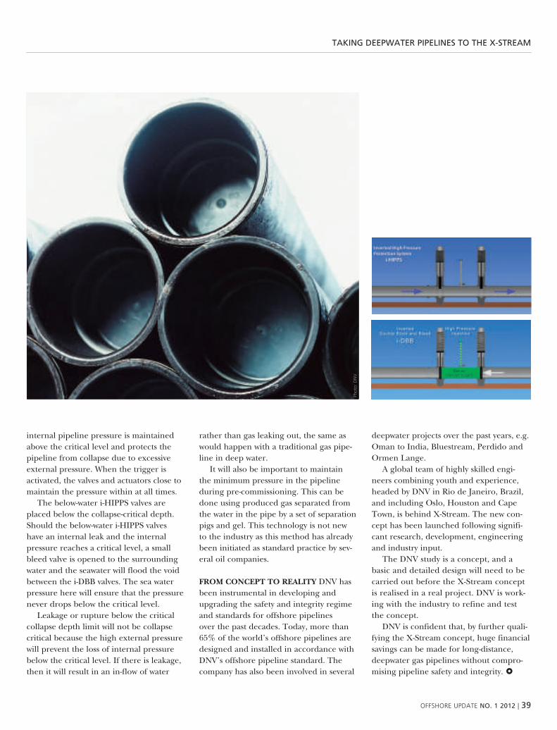
oFFshore uPDate NO. 1 2012 | 39
takiNg Deepwater pipeliNes tO the x-streaM
internal pipeline pressure is maintained above the critical level and protects the pipeline from collapse due to excessive external pressure. when the trigger is activated, the valves and actuators close to maintain the pressure within at all times.
the below-water i-hipps valves are placed below the collapse-critical depth. should the below-water i-hipps valves have an internal leak and the internal pressure reaches a critical level, a small bleed valve is opened to the surrounding water and the seawater will flood the void between the i-dbb valves. the sea water pressure here will ensure that the pressure never drops below the critical level.
leakage or rupture below the critical collapse depth limit will not be collapse critical because the high external pressure will prevent the loss of internal pressure below the critical level. if there is leakage, then it will result in an in-flow of water
rather than gas leaking out, the same as would happen with a traditional gas pipe-line in deep water.
it will also be important to maintain the minimum pressure in the pipeline during pre-commissioning. this can be done using produced gas separated from the water in the pipe by a set of separation pigs and gel. this technology is not new to the industry as this method has already been initiated as standard practice by sev-eral oil companies.
FrOM cONcEPT TO rEaLITy dnv has been instrumental in developing and upgrading the safety and integrity regime and standards for offshore pipelines over the past decades. today, more than 65% of the world’s offshore pipelines are designed and installed in accordance with dnv’s offshore pipeline standard. the company has also been involved in several
deepwater projects over the past years, e.g. oman to india, bluestream, perdido and ormen lange.
a global team of highly skilled engi-neers combining youth and experience, headed by dnv in rio de Janeiro, brazil, and including oslo, houston and cape town, is behind X-stream. the new con-cept has been launched following signifi-cant research, development, engineering and industry input.
the dnv study is a concept, and a basic and detailed design will need to be carried out before the X-stream concept is realised in a real project. dnv is work-ing with the industry to refine and test the concept.
dnv is confident that, by further quali-fying the X-stream concept, huge financial savings can be made for long-distance, deepwater gas pipelines without compro-mising pipeline safety and integrity.
Phot
o: D
nv

40 | oFFshore uPDate NO. 1 2012
eNergy eFFicieNcy FOr Osvs
energy efficiency for osvstoday, two segments of the maritime industry that continue to remain buoyant and attract a lot of investment and new orders are the Lng carrier and offshore support vessel (osv) markets.
teXt: TONy TEO, dnv
lng carriers’ day rates continue to surge ahead and are currently at over usd 150,000 per day, while the osv segment, depending on vessel features, is averaging rates of usd 30,000 a day. the annual return on revenue of an lng carrier and osv are 23 per cent and 22 per cent respectively, representing the best invest-ments in the maritime market today.
the quest for deepwater activity has brought with it the need for osvs with dp capabilities, and rig deliveries have kicked up the need for more sophisti-cated osvs. companies that have recently announced orders include hornbeck, with sixteen vessels, harvey gulf, with
four lng-fuelled osvs, and bp ship-ping, which is behind four osv orders in korea. in brazil, an estimated one hun-dred osvs will be needed for its increas-ing offshore activities.
ENVIrONMENTaL LEGISLaTION mean-while, all osv operators need to be aware of the environmental considerations involved in running their fleets. today, the shipping industry has an annual co2 emis-sion level equivalent to that of the entire nation of germany. in the past, shipping was “exempt” from emissions legislation since it was international and therefore difficult to regulate. however, there has
been a steadily increasing focus on ship-ping over the last decade, which is why the industry has to be proactive.
For example, the waters along the coasts of north america will soon be an emissions control area (eca). in march 2010, the international maritime organi-zation (imo) amended the international convention for the prevention of pollu-tion from ships (marpol), designating specific portions of north america as an eca, and this will become enforceable in august 2012. the eca extends 200 n-miles from north american shores and includes all inland waterways (including the great lakes) as well as portions of alaska and
›› tony teo, Business Development Director, maritime north america. Picture taken on a teekay tanker a few years ago.Ph
oto:
mag
ne a
. rø
e

oFFshore uPDate NO. 1 2012 | 41
eNergy eFFicieNcy FOr Osvs
›› the Dnv-classed, Lng-powered Viking Energy.
Phot
o: h
aral
d m
. v
alde
rhau
g

42 | oFFshore uPDate NO. 1 2012
eNergy eFFicieNcy FOr Osvs
hawaii. this applies to all ships in the us eca, including vessels registered to nations that are not party to marpol annex vi.
key measures within ecas include:■■ 1 august 2012: max 1% sulphur fuel is permissible
■■ January 2015: 0.1% sulphur fuel is permissible
■■ scrubbing is allowed as an equivalent measure. the same applies to lng fuel.
■■ higher sulphur fuel can be burned if an equivalent emission reduction is obtained via scrubbers or other technologies.
globally, co2, sox and nox are key regulatory issues now. sox and nox regulations are in place, with stricter regulations coming into force. co2 regula-tions are under development, but subject to tremendous political difficulties. the refinery industry, too, has already warned that it will have difficulties in meeting the demand for low sulphur fuels when the introduction of the imo’s global 0.50% sulphur limit comes into force in 2020, let alone the eca sulphur limit in 2015.
over and above specific emissions-relat-ed measures, in 2010 the imo announced an initiative to introduce an energy effi-ciency design index (eedi), a shipboard energy efficiency management plan (seemp), energy efficiency operational index (eeoi), and market-based meas-ures (mbms).
marpol annex vi, which enters into force on 1 January 2013, makes the eedi and seemp mandatory. the eedi requirements will apply to new ships above 400 tonnes.
the eedi is a set of targets for specific ship types against which newbuildings will be benchmarked. the regulations call for designs to be more efficient than the benchmark, which becomes tougher over time for subsequent newbuildings.
the amendment stipulates that an international energy efficiency certificate (ieec) is to be issued on the first renewal or intermediate survey after 1 January 2013. the certificate requires, amongst
other things, the presence of a ship ener-gy management plan (seemp) on board. no changes were made to the seemp at mepc 62.
regulations for diesel-electrical and steam-propelled ships were put on hold until a method of calculation can be developed. the following are applicable to osvs:■■ ships with a diesel-electric, turbine or hybrid propulsion system will not be included before calculation methods are developed
■■ reduction factors for small vessels are to be reviewed in 2013
■■ there will be a review in 2015 based on technological developments, and this may lead to adjustments to dates and rates
in designing an energy-efficient osv, four main areas need to be looked at: the hull, propulsion, machinery and other options.
HuLL SOLuTIONS an optimised stream-lined hull is one that is based on the most used speed and draft conditions. this, along with other features like flipper fins and bow forms, such as the wave-piercing type, needs to be verified by model testing and analyses. placing the accommodation and superstructure aft as on the viking lady can be an obvious solution, as less displacement is required at the bow, allowing the implementation of finer hull lines. another solution involves the use of retractable bow thrusters, which reduce drag. another method is to install an air
›› Lng fuelling station.Ph
oto:
Per
sve
rre
wol
d-h
anse
nPh
oto:
Per
sve
rre
wol
d-h
anse
n

oFFshore uPDate NO. 1 2012 | 43
eNergy eFFicieNcy FOr Osvs
lubrication system. air lubrication on the flat bottom plating using compressed air can reduce drag significantly. in addition, new hull forms to minimise the ballast requirement and thereby increase the cargo capacity are being considered.
PrOPuLSION SySTEMS various configu-rations of propeller blades and types can add power savings of between two and eight per cent. the installation of nozzles and ducts, propeller boss cap fins, contra-rotating propellers, a rudder-propeller transition bulb or rudder fins are some examples of this.
MacHINEry cHOIcES in recent years, engine makers have carried out studies which have led to a number of innovative
designs. diesel electric propulsion technol-ogy is continuing to evolve as the demand for more energy-efficient machinery increases. the easy integration of mod-ern large-scale battery systems based on lithium technology makes it favourable and financially viable to install batteries on board. in relation to this, a new battery power class notation has just been devel-oped by dnv.
another innovation, hybrid shaft gen-erators, can be incorporated into the main and auxiliary engines. at cruising speeds, the hybrid shaft generators produce elec-tricity for other consumers, while at slow speed they switch to become a motor pow-ered by the auxiliary engine(s). whether it is diesel or gas-powered, multiple or smaller capacity engine arrangements that
generate electricity, they can contribute to reduce fuel consumption as only what is required is produced.
other fuel-saving features include waste heat recovery systems to feed into exhaust gas boilers, water makers and accommoda-tion climate heating.
OTHEr OPTIONS superstructures can be replaced by lighter materials such as fire-proof composite materials, saving as much as 50 per cent in weight and thus allowing more cargo-carrying capacity. electric cranes and winches can replace hydraulic versions as they are typically 15 to 20 per cent more efficient as well as being less noisy and having lower pollu-tion risks.
when it comes to seemp, there are no quick-fixes, but a combination of a number of different measures can bring about significant results. these include weather routing, speed optimisation, auto pilot setting, engine monitoring, analysis of on-board energy consumers (opera-tions relating to the cargo/crane, dp/thruster, ventilation system /hvac/lights, incineration), propeller polishing, hull coatings and cleaning, and fuel sampling. but it is not just technology or product analysis that needs consideration in light of seemp. human interaction, such as improved cooperation between owners and charterers, crew competence and training measures are also vital, yet less often reflected upon.
cONcLuSION as fuel prices soar, char-terers are beginning to scout for energy-efficiency-rated ships. once delivered, hull forms are difficult to change. For the industry to stay ahead, yards need to start building more energy-efficient osv hulls. although eedi and seemp may not immediately apply to small ships and ships on domestic trades, it is wise for a prudent owner or operator to look into these regulations when ordering new ships or operating existing ones. the ben-efits will be better and longer-term finan-cial results, higher asset resale values and less air emissions.
Phot
o: P
er s
verr
e w
old-
han
sen

44 | oFFshore uPDate NO. 1 2012
the premise of the project was that indus-try cooperation should look at technical standards which can be used internation-ally. regulations and laws are national and outside the remit of this project.
phase 1 (october 2007–october 2008) produced five “position papers” and established the norwegian-russian partnership model for this project; dnv as the norwegian/international project manager and technical committee 23 (vniigaz/gazprom) as the russian pro-ject manager. this project management structure has been retained throughout the project.
in phase 2 (november 2008–march 2009), the financial industry sponsors selected from a range of topics and priori-tised seven key areas to be examined in
further detail by seven specialist working groups. in this phase, the project partici-pants agreed to use the existing safety level in the north sea as a benchmark for the barents sea. due to the more difficult consequence scenario – e.g. search, res-cue and clean-up – the project concluded that an acceptable safety level could pri-marily be reached by reducing the prob-ability of incidents and accidents. this confirmed the project’s focus on improv-ing standards.
the seven working groups in phase 3 (may 2009–march 2010) focused on bar-ents sea (i) common offshore standards, (ii) ice loads,(iii) risk management,(iv) escape, evacuation and rescue,
(v) working environment,(vi) loading/unloading and ship
transportation,(vii) operational emissions and discharges
to air and water.
their joint report was issued in march 2010 and included a list of 130 – mostly functional – standards recommended for common use. many of the standards could be used in the barents sea without revi-sions, while several others needed revisions or further written guidance.
this report – for phase 4 (may 2010–march 2012) – is the final result of the barents 2020 project. the industry spon-sors – in phase 4 they were gazprom, stat-oil, eni, total, ogp and dnv – agreed to bring forward from phase 3 those issues
bareNts 2020 cONclusive suMMary
barents 2020 conclusive summary
the Barents 2020 project commenced after the norwegian ministry of Foreign affairs requested and funded a Dnv-led effort to seek industry cooperation with russia in order to harmonise and agree on hse standards for use in the Barents sea. it was understood that the Barents sea represents new safety challenges for both
norway and russia, and that russian cold climate experience could fruitfully be merged with norwegian offshore competence.
teXt: LEIF MaGNE NESHEIM, dnv

oFFshore uPDate NO. 1 2012 | 45
bareNts 2020 cONclusive suMMary
Phot
o: g
eost
ock/
Phot
odis
c/g
etty
imag
es
and topics that were in greatest need of completion, revision and detailed guid-ance. in phase 4, the project formally became international, although there had already been strong participation by international specialists in phase 3. these included French, american and dutch specialists – just to mention a few. all in all, approximately 100 specialists from 40 organisations and companies participated in phase 4.
the steering committee has consisted of the industry sponsors joined by iso representatives rosstandard of russia and standard norge of norway.
the seven working groups from phase 3 were kept intact and continued their work with renewed tasks and mandates in phase 4.
Five of the seven groups (2, 4, 5, 6, and 7) were tasked with detailing and formulat-ing recommendations to remedy the main deficiencies within their focus areas. these recommendations have been submitted – primarily iso tc 67’s 19906 standard, and to the new tc67 subcommittee 08, “arctic operations”. independently of this, companies are free to use the deliverables as project-specific standards, and national standardisation bodies will also implement recommendations as they see fit.
group number 1 was tasked with recom-mending and guiding the process of for-matting and channelling the deliverables and results to the correct standardisation addresses.
group number 3 – risk management – did not recommend any new standards,
and was tasked with running seminars with representatives from regulators and com-panies to exemplify through cases how risk management can be applied in cold climate field developments.
the steering committee and plenum conference reviewed, commented on and approved the results in moscow on 14–15 december 2011. this report documents the results and recommendations of all the working groups. it reads as a sequel to the phase 3 report (march 2010). to obtain full value of the results, both reports should thus be read.
this is the final and conclusive deliver-able from the barents 2020 industry coop-eration project. dnv and vniigaz – as project managers – thus also conclude their work here.

46 | oFFshore uPDate NO. 1 2012
Phot
o: g
etty
imag
es
wellstreaM
wellstream awarded dnv’s local content certification for brazilian operations
expected investments in its oil and gas industry of approximately usD 400 billion over the next 10 years present Brazil with a unique opportunity to develop its local oil and gas expertise.
teXt: jOSE PONTES, dnv
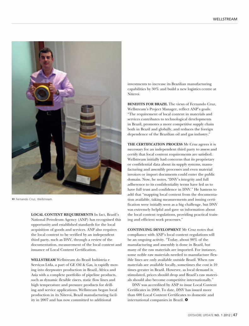
oFFshore uPDate NO. 1 2012 | 47
wellstreaM
LOcaL cONTENT rEquIrEMENTS in fact, brazil’s national petroleum agency (anp) has recognised this opportunity and established standards for the local acquisition of goods and services. anp also requires the local content to be verified by an independent third party, such as dnv, through a review of the documentation, measurement of the local content and issuance of local content certification.
wELLSTrEaM wellstream do brasil indústria e serviços ltda, a part of ge oil & gas, is rapidly mov-ing into deepwater production in brazil, africa and asia with a complete portfolio of pipeline products, such as dynamic flexible risers, static flow lines and high temperature and pressure products for drill-ing and service applications. wellstream began local production in its niteroi, brazil manufacturing facil-ity in 2007 and has now committed to additional
investments to increase its brazilian manufacturing capabilities by 30% and build a new logistics centre at niteroi.
BENEFITS FOr BraZIL the views of Fernando cruz, wellstream’s project manager, reflect anp’s goals. “the requirement of local content in materials and services contributes to technological developments in brazil, promotes a more competitive supply chain both in brazil and globally, and reduces the foreign dependence of the brazilian oil and gas industry.”
THE cErTIFIcaTION PrOcESS mr cruz agrees it is necessary for an independent third party to assess and certify that local content requirements are satisfied. wellstream initially had concerns that its proprietary or confidential data about its supply systems, manu-facturing and assembly processes and even material invoices or import documents could enter the public domain. now, he notes, “dnv’s integrity and full adherence to its confidentiality terms have led us to have full trust and confidence in dnv.” he hastens to add that “mapping local content from the documenta-tion available, taking measurements and issuing certi-fication were initially seen as a big challenge, but dnv was extremely helpful and gave us information about the local content regulations, providing practical train-ing and efficient work processes.”
cONTINuING DEVELOPMENT mr cruz notes that compliance with anp’s local content regulations will be an ongoing activity. “today, about 90% of the manufacturing and assembly is done in brazil, but many of the raw materials are imported. For instance, some noble raw materials needed to manufacture flex-ible lines are only available outside brazil. when raw materials are available locally, sometimes the cost is 10 times greater in brazil. however, as local demand is stimulated, prices should drop and brazil’s raw materi-als should also become competitive internationally.”
dnv was accredited by anp to issue local content certificates in 2008. to date, dnv has issued more than 600 local content certificates to domestic and international companies in brazil.
Phot
o: D
nv
›› Fernando cruz, wellstream.

48 | oFFshore uPDate NO. 1 2012
Deepwater Drives the DevelOpMeNt OF New techNOlOgy
deepwater drives the development of new technology
the limitations of today’s technology are being challenged as the oil and gas industry goes far offshore, into deeper waters and further into the crust of the earth, to exploit oil and gas. new technology has
to be developed and qualified to make these resources economically viable and ensure safe operations.
teXt: HaNS BraTFOS, dnv
we can see fascinating developments driven by the deepwater fields in the outer gom and west africa and the brazilian pre-salt fields. mexico, india and china will also go in for deeper water prospects. petrobras has ambitious plans for the pre-salt developments, involving short- and long-term goals along the whole produc-tion process, from reservoir to beach.
to get an idea of what is on the gom operators’ agendas, take a look at
deepstar’s next phase Xi programmes. hydrate management, as opposed to hydrate avoidance, is an area of high atten-tion. some of the other focus areas are dry trees, mooring, viv, new solutions relating to drilling & completions, subsea process-ing and reservoir technology.
in brazil, operators are required to invest 1% of their revenue in r&d, boost-ing technology development to prepare the o&g industry in brazil to cope with
the medium- and long-term challenges. remoteness from shore and existing infra-structure challenge the logistics relating to both humans and hydrocarbons. deeper waters and high well pressures demand new production systems for subsea process-ing, pipelines and risers. developing riser-less drilling is just one example of ambi-tious technology goals that make o&g one of the most exciting industries for engi-neers in the next few decades.
›› hans axel Bratfos, Directory of technology, services and Quality.
›› aerial of the helix Q4000 taken shortly before “static kill” procedure began at mc 252 site in gulf of mexico, on 03 august 2010.
Phot
o: D
nv
Phot
o: B
P p.
l.c.

oFFshore uPDate NO. 1 2012 | 49
west aFricaN gas pipeliNe
west african gas pipelinethe west african gas Pipeline is an unusual example of cooperation
in a difficult environment and on complex energy issues.
teXt: PETEr HaMEr, dnv
the west african gas pipeline company (wagpco) is a joint venture consisting of national interests, with nigeria, ghana, togo and benin partnering with chevron to create a viable energy solution so that nigeria’s gas production can meet its neighbours growing energy demands. the 678km west african gas pipeline (wagp) links up with the existing escravos-lagos pipeline at the nigeria gas company’s itoki natural gas export terminal in nigeria and proceeds to a beachhead in lagos. From there it moves offshore to takoradi in ghana, with gas delivery later-als from the main line extending to coto-nou (benin), lome (togo) and tema
(ghana). the escravos-lagos pipeline system has a capacity of 800 mmscfd, and the wagp system will initially carry a vol-ume of 170mmscfd and peak over time at a capacity of 460mmscfd.
dnv ghana and dnv capetown’s pipeline experts met with wagpco in 2011 and discussed the various operational challenges facing this multinational joint venture. dnv’s local expertise was able to help define the joint venture’s core pipe-line risk management needs and subse-quently worked with wagpco to develop its asset integrity management plan.
the asset integrity management of pipe-lines in west africa is a critical element
for the continued success of large projects in not only the established producing countries of nigeria and angola but also the emergent nations such as ghana and the booming east african arena. Field lives are being continually extended beyond the planned life cycles and more com-plex analysis is being sought to provide confidence in these pipelines, which are revenue-critical assets.
dnv africa is now playing a strong role in providing local expertise with a global perspective and creating solutions on the ground with its local partners.
›› Peter hamer, Director of operations. ›› Petrochemical processing equipment at oil refinery, nigeria.
Phot
o: D
nv
Phot
o: g
etty
imag
es

50 | oFFshore uPDate NO. 1 2012
›› testing for BP’s mad Dog project.
Phot
o: B
P
MOOriNg systeMs iN Deepwater FielDs
mooring systems in deepwater fields
what’s new in moorings at Dnv? Dnv has been very active in mooring systems for both mobile drilling and floating production units (FPus) since the
1970s, and continues to play a leading role in offshore moorings.
teXt: VIDar ÅHjEM and rOBErT GOrDON, dnv

oFFshore uPDate NO. 1 2012 | 51
MOOriNg systeMs iN Deepwater FielDs
MOOrING cHaLLENGES aND THE DEVELOPMENT OuTLOOK as the demand for offshore production grows worldwide, the num-ber of mooring systems in service is increasing. the average age of the worldwide fleet of Floating production units (Fpus) is also increasing. Fpus are now installed offshore on six continents, in climates ranging from tropical to polar. the water depth for new Fpus is continuing to increase, with shell’s perdido spar now holding the world record for a per-manently moored floating production system at 2,450 metres (8,000 feet). at this depth, mooring is made pos-sible by the use of fibre ropes.
since starting to test very large fibre ropes for offshore mooring at its labora-tory in bergen, dnv has taken an active part in also developing this part of off-shore mooring technology together with the industry.
the laboratory was built to meet the testing needs of the barracuda & carat-inga and mad dog projects in the early 2000s, with their respective 1,250-tonne and 1,932-tonne capacities. later, dnv’s laboratory performed the mooring rope testing for the cascade & chinook project to verify compliance with dnv classifica-tion requirements.
SETTING STaNDarDS in 2008, the stand-ard for certification no. 2.13 was super-seded by dnv-os-e303 offshore mooring Fibre ropes, which has served the industry ever since. the introduction of approval programmes for yarn and rope makers in standard for certification no. 2.9 in 2010 helped standardise the documentation processes, and currently work is ongoing to refine and complement the documents available to the industry.
GETTING OLDEr – MOOrING INTEG-rITy MaNaGEMENT as Fpus grow older, managing the degradation of moorings is becoming increasingly important. although degradation over time is con-sidered during the design phase, it is
important to keep it at a minimum and even be able to extend the service life of installations. wear, corrosion and fatigue are the primary sources of degradation, and must be managed in the same way as operating costs. dnv is helping the industry by developing guidelines for risk-based mooring integrity management. once completed, these guidelines will allow the efficient and effective inspection of mooring systems.
NOrMOOr – rEVISED SaFETy FacTOrS FOr MOOrING LINE DESIGN the objective of the ongoing nor-moor Jip is to calibrate safety factors for mooring line design so that they provide the target reliability. the initial work is looking at the ultimate limit state (uls). additional phases may consider accidental and fatigue limit states.
FIBrE rOPE TEcHNOLOGy DEFINES THE FuTurE OF MOOrINGS as Fpu water depths increase, the need for strong, lightweight synthetic mooring ropes is also increasing. deepwater moorings (more than about 1,000 meters or 3,000 feet) around the world now rely on polyester mooring ropes.
an important topic for the future is
‹‹ mooring rope for the cascade & chinook project.
Phot
o: L
ankh
orst

52 | oFFshore uPDate NO. 1 2012
MOOriNg systeMs iN Deepwater FielDs
the definition, measurement and expression of fibre-rope change-in-length characteristics. this is an area which the industry has been grappling with for the past 15 years or more due to the non-linear, visco-elastic behaviour of synthetic mooring lines. a major milestone in this process was the definition of the analogue model (Flory) in a comprehensive Joint indus-try project in which dnv cooperated with key members of the industry. the analogue model provides an illustration of rope responses to changes in tension, making it much easier to understand the way the rope behaves. /1/
the mechanical properties of the fibre rope are what will drive the behaviour of deepwa-ter mooring systems. this means that it is the axial properties and length of the rope that govern the mooring system restoring forces and platform offset, and the fatigue loading of connected steel components. hence, the focus must be on a design that balances strength with change-in-length and fatigue resistance; oversizing the rope will reduce the fatigue design margins.
SyrOPE – GLOBaL PErFOrMaNcE OF SyNTHETIc rOPE MOOrING thus, it is essential to characterise the nonlinear tension-elongation behaviour of the mooring system as a whole.
as kjell larsen of statoil explains: “applying the exact physical behaviour of fibre rope in off-shore mooring analyses is extremely important to deepwater field development; and with the on-going syrope pilot studies implemented for poly-ester we will also be able to harness the potential of using other synthetic materials if needed.”
as a result of these needs, statoil, dnv and sinteF marintek are co-operating closely to develop the new gen-eration of mooring design software algorithms for synthetic moorings. /2/ this project is called syrope and statoil has already implemented “best design practice” as a result of the pilot project findings. the pilot study will be completed during the spring of 2012, and a follow-up Joint industry project will be launched in 2012.
the syrope Jip will develop improved algorithms for
predicting the global performance of synthetic rope moor-ings and should be able to bring the analysis models for fibre rope systems to a mature level. this Jip will include synthetic-rope testing, the development of advanced numerical mooring models, case studies and the devel-opment of an analysis guideline for fibre rope mooring systems.
as shown in Figure 1, in the traditional catenary moor-ing system, the weight and geometric stiffness of the moor-ing system provide the main stiffness characteristics. in
›› test machine the Bristle worm.
Phot
o: D
nv
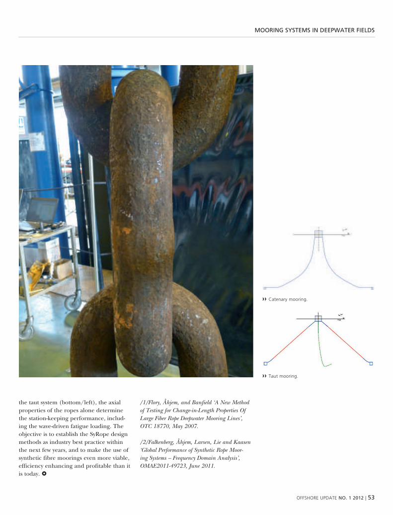
oFFshore uPDate NO. 1 2012 | 53
MOOriNg systeMs iN Deepwater FielDs
›› taut mooring.
›› catenary mooring.
the taut system (bottom/left), the axial properties of the ropes alone determine the station-keeping performance, includ-ing the wave-driven fatigue loading. the objective is to establish the syrope design methods as industry best practice within the next few years, and to make the use of synthetic fibre moorings even more viable, efficiency enhancing and profitable than it is today.
/1/Flory, Åhjem, and Banfield ‘a New Method of testing for Change-in-Length Properties of Large Fiber rope Deepwater Mooring Lines’, otC 18770, May 2007.
/2/Falkenberg, Åhjem, Larsen, Lie and Kaasen ‘Global Performance of Synthetic rope Moor-ing Systems – Frequency Domain analysis’, oMae2011-49723, June 2011.
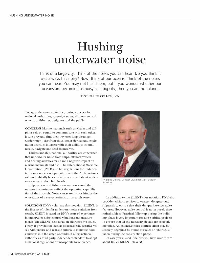
54 | oFFshore uPDate NO. 1 2012
hushiNg uNDerwater NOise
hushing underwater noise
think of a large city. think of the noises you can hear. Do you think it was always this noisy? now, think of our oceans. think of the noises
you can hear. you may not hear them, but if you wonder whether our oceans are becoming as noisy as a big city, then you are not alone.
teXt: BLaINE cOLLINS, dnv
today, underwater noise is a growing concern for national authorities, sovereign states, ship owners and operators, fisheries, designers and the public.
cONcErNS marine mammals such as whales and dol-phins rely on sound to communicate with each other, locate prey and find their way over long distances. underwater noise from ships, sonar devices and explo-ration activities interfere with their ability to commu-nicate, navigate and feed themselves.
understandably, national authorities are concerned that underwater noise from ships, offshore vessels and drilling activities may have a negative impact on marine mammals and fish. the international maritime organization (imo) also has regulations for underwa-ter noise on its development list and the arctic nations will undoubtedly be especially concerned about under-water noise in the high north.
ship owners and fishermen are concerned that underwater noise may affect the operating capabili-ties of their vessels. noise can scare fish or hinder the operations of a survey, seismic or research vessel.
SOLuTIONS dnv’s voluntary class notation, silent, is the first set of rules for underwater noise emissions from vessels. silent is based on dnv’s years of experience in underwater noise control, vibrations and measure-ments. the silent class notation addresses two issues. Firstly, it provides the owners of acoustically sensitive ves-sels with precise and realistic criteria to minimise noise emissions into the water. secondly, it offers national authorities a third-party, independent standard to adopt as national regulations or incorporate by reference.
in addition to the silent class notation, dnv also provides advisory services to owners, designers and shipyards to ensure that their designs have low-noise features. however, noise control is not a purely theo-retical subject. practical follow-up during the build-ing phase is very important for noise-critical projects to ensure that all the necessary details are correctly included. an extensive noise-control effort may be severely degraded by minor mistakes or “short-cuts” taken during the construction phase.
in case you missed it before, you have now “heard” about dnv’s silent class.
›› Blaine collins, Director Divisional staff, Division americas.
Phot
o: D
nv

oFFshore uPDate NO. 1 2012 | 55
hushiNg uNDerwater NOise
Phot
o: is
tock
marine mammals such as whales and dolphins rely on sound to communicate with each other, locate prey and find their way over long distances. underwater
noise from ships, sonar devices and exploration activities interfere with their ability to communicate, navigate and feed themselves.

56 | oFFshore uPDate NO. 1 2012
MaiNteNaNce
maintenance of mobile offshore units and floating structures
– it’s only getting bettersixty per cent of the world’s offshore fleet is past its theoretical design age of 20 years. rigs and production platforms are being kept in operation for
prolonged periods, well beyond their anticipated design life.
teXt: MIcHIEL VaN DEr GEEST, dnv
as a class society, one of dnv’s key services is help-ing owners to ensure the reliability and safety of their assets by providing them with effective and efficient maintenance methodologies and techniques. indeed, dnv has recently published two new recommended practices (rp) for bonded repairs of steel structures and lowering maintenance and/or inspection costs.
DNV-rP-c301, rEcOMMENDED PracTIcE FOr THE DESIGN, FaBrIcaTION, OPEraTION aND quaLIFIcaTION OF BONDED rEPaIrS OF STEEL STrucTurEs welded repairs of floating structures can become extremely costly as hot-work may lead to shutdowns and considerable loss of revenue. this has led to increasing interest in using cold repair meth-ods. to develop guidelines for bonded patch repairs of Fpso structures, dnv launched a Joint industry project which led to dnv’s recommended practice for bonded repairs. this approach allows consider-able cost savings and the minimum interruption to operations.
the principle of a bonded repair is shown in Fig-ure 1. the structure was designed for certain loads, but has to be repaired once fatigue or corrosion dam-age reduces its capability and strength. instead of welding, with the hot-work issues involved, a stiff and strong patch is bonded onto the structure to restore its integrity.
dnv’s rp provides guidance on the cold repair of non-critical defects and the installation of secondary structures, as well as criticality assessments of defects,
the design of a patch, qualification of materials and patches, fabrication on site and final inspection. additionally, the rp provides a method to predict the capacity of bonded patches.
one example of a bonded repair is shown in Figure 2.
DNV-rP-c302, rISK-BaSED cOrrOSION MaNaGE-MENT this is a holistic approach to assist owners in lowering corrective maintenance inspection costs. unlike traditional planned inspections and reactive corrective maintenance, the dnv rp approach pro-vides tools for a quantitative comparison of corrosion damage and required remediation, as well as clear communication of the damage and repairs to the owner’s management.
a key advantage of this approach is that it can be applied generally or with different levels of implementation without losing its practicability and effectiveness. it can be used for units ranging from those under construction to older units, from units in benign waters to units in harsh conditions, from inspections based on existing information to complete and extensive analyses.
with these two rps, dnv has introduced two practical tools; one targeting technical aspects, bonded repairs, and the other guiding the implementation of manage-ment systems for corrosion control. together, these two tools support a reduction in overall maintenance and repair costs.

oFFshore uPDate NO. 1 2012 | 57
MaiNteNaNce
›› Figure 2: the standard process as described by iso-31000, risk management, on the left, and the practical approach of Dnv’s rP on the right.
›› Figure 1: concept of the bonded patch repair for cracks and corrosion.
Mo
nit
ori
ng
an
d R
evie
w
Establishing the Context
Risk Identification
Risk Analysis
Risk EvaluationRIS
K A
SSES
SMEN
T
Risk TreatmentStep 4
Remediation & Repair
Step 3Detail Evaluation
Step 2Risk Ranking
Step 1Risk Assessment
Step 5
Life Cycle M
anag
emen
t
©D
nv
/nin
a ra
ngøy

58 | oFFshore uPDate NO. 1 2012
DNv hOustON
dnv houston shows software integrity
Dnv has a long history of working with software-dependent systems across a range of industries, including automotive, telecom
and aerospace. in 2008, Dnv released a recommended Practice for integrated software Dependent systems (Dnv-rP-D201).
teXt: rIcHIE MacTaGGarT
the isds methodology has been built on dnv’s decades of experience in address-ing the software integrity of embedded sys-tems, and the methodology represents the industry’s most comprehensive and effec-tive software-related risk management tool to date. after piloting isds in more than 10 offshore projects, the recommended practice was promoted to a tentative off-shore standard in 2010 (dnv-os-d203). in 2011, the offshore standard and associ-ated class notation were released in their final version, ready to be applied in pro-jects worldwide.
isds can be applicable to any parts of the hydrocarbon chain and is finding favour among energy companies in the gulf of mexico. it is a collection of best practices for software developers in oil and gas, service and dedicated software compa-nies. its popularity is growing as the indus-try shifts from mechanically orientated to software-managed solutions.
allen prescott, pmp and csqe senior consultant, dnv, houston, says: “isds comprises a week-long assessment. during this time dnv, looks at all the processes and procedures of a software development company or department and creates a gap analysis. dnv shows the documentation created during the product development process, such as work instructions. best practice documentation also needs to be full and complete – along with whether employees are following procedures. we
are now seeing rig owners ask for software to be isds compliant and this is often specified in tender documents.”
the use of isds enables developers to find bugs more easily. isds-compliant processes ensure that software is tested correctly because they create mapping and traceability and set out methods to ensure that requirements are being implemented.
it was actually the industry that asked for these procedures to be in place. more rigs and other systems are now utilising software and other electrical controls, so operators began requesting isds.
dnv’s houston office is concentrating on two services:
pre-qualification: whereby dnv looks at how companies are developing products and how capable these products are of being compliant with isds.
there are a lot of process models, along with iso standards, and this has become a subset of best practices. the capability maturity model, for example, is a qualifica-tion procedure for companies that have large programming and developing departments. however, this was too exten-sive for most development departments in the oil & gas industry and isds is seen as being more applicable to them – par-ticularly for analysing safety and uptime processes.
classification: when isds is added to a new build and filters down to suppli-ers, they have to be compliant with isds
requirements. dnv is more involved in the verification process. For example, a new rig owner can specify that it wants all soft-ware to be isds compliant throughout the product supply chain.
out of houston, dnv has recently com-pleted one pre-qualification of a large sup-plier of various components for offshore products. a final letter of compliance is valid for one year. if the supplier does not participate in a new class project, it will need to re-qualify. otherwise, if it has
›› Dnv houston office.
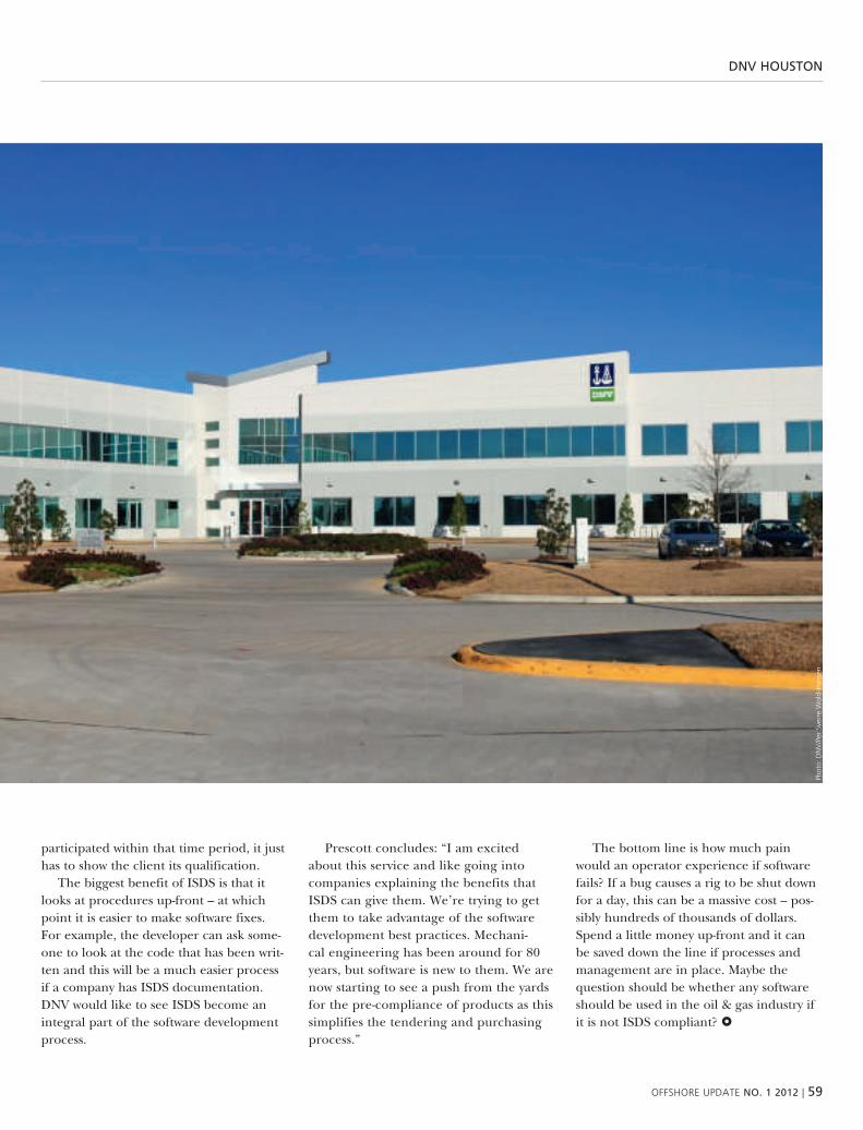
oFFshore uPDate NO. 1 2012 | 59
DNv hOustON
participated within that time period, it just has to show the client its qualification.
the biggest benefit of isds is that it looks at procedures up-front – at which point it is easier to make software fixes. For example, the developer can ask some-one to look at the code that has been writ-ten and this will be a much easier process if a company has isds documentation. dnv would like to see isds become an integral part of the software development process.
prescott concludes: “i am excited about this service and like going into companies explaining the benefits that isds can give them. we’re trying to get them to take advantage of the software development best practices. mechani-cal engineering has been around for 80 years, but software is new to them. we are now starting to see a push from the yards for the pre-compliance of products as this simplifies the tendering and purchasing process.”
the bottom line is how much pain would an operator experience if software fails? if a bug causes a rig to be shut down for a day, this can be a massive cost – pos-sibly hundreds of thousands of dollars. spend a little money up-front and it can be saved down the line if processes and management are in place. maybe the question should be whether any software should be used in the oil & gas industry if it is not isds compliant?
Phot
o: D
nv
/Per
sve
rre
wol
d-h
anse
n

60 | oFFshore uPDate NO. 1 2012
DNv sOFtwareDnv software is a leading provider of software for managing risk in the energy, process and maritime industries – offering solutions for design, engineering, strength assessment, risk and reliability, Qhse and asset integrity management. Dnv software is part of Dnv and almost 300 Dnv offices in 100 countries enable us to be close to our customers and share best practices and quality standards worldwide.
Phot
o: is
tock
phot
o
syNergi
synergi looks to asia and the americas
Dnv software is significantly expanding the sales of its synergi software, with an added focus on the markets in the americas and asia after the software’s success in
europe. although this expansive strategy was implemented as recently as in January of this year, synergi has already landed some major contracts in north america.
teXt: KaIa MEaNS

oFFshore uPDate NO. 1 2012 | 61
syNergi
syNergisynergi is a complete and user-friendly solution that manages all non-conformities, incidents, risks, risk analyses, audits, assessments and improvement suggestions. it covers every workflow process, such as reporting, processing, analysing, corrective actions, communication, experience transfer, trending and kPi monitoring.
synergi eases communication and cooperation throughout the organisation, leading to increased efficiency and improved Qhse performance. synergi has multi-language capabilities and reporting is intuitive and self-instructive. Lessons learned are shared, and repeat errors are prevented.
Based on the analysis of statistics and reported incidents, managers can confidently suggest and implement actions, ensuring a secure workplace in many different industries, such as health care, petrochemical, maritime, transport and oil & gas.Ph
oto:
isto
ck
two major signings are just the start of synergi’s push into the americas and asian markets with its risk and qhse man-agement solution.
in march, two new major synergi con-tracts were signed in north america. the first was with canada’s talisman energy, which is based in calgary. talisman will be rolling synergi out to all business units worldwide. the second was with houston-based marathon oil corporation, where a local synergi live trial last year will now be replaced by a corporate platform physi-cally placed in houston but for global use. by 2013, a full 4,000 marathon oil professionals will be using the system in four different languages, trusting synergi and dnv to strengthen their operational integrity.
hess corp. is moving on to the latest version and expanding its use of syn-ergi to include the advanced synergi® risk management™ module. recently it became clear that ensco is also looking to expand its use of synergi in 2012.
when dnv software acquired synergi in may last year, the new management team immediately started implement-ing a strategy to increase synergi’s global presence, relying on dnv’s cur-rent footprint of nearly 300 offices in 100 countries.
synergi is building on its market-leading position in europe and beyond within the oil & gas sector. some 80 per cent of the major oil & gas players in the north sea rely on synergi for operational risk and qhse management. the synergi brand is extremely strong in europe and, with the help of the worldwide dnv network, opportunities are growing.
“we have an exciting few years ahead of us,” says principal regional sales manager stein olav skarbø. “we firmly believe that in the americas, the world’s single larg-est economy, there is an opportunity to support larger organisations that have the necessary maturity to implement synergi,” he says.
“us and canadian companies’ strate-gies in particular are becoming more long-term, especially within the oil & gas industry. in dnv software, our focus is on long-term strategy, stability and integrity, facilitated by acknowledged tools like syn-ergi. the american market is absolutely ready for this, and synergi is certainly fit for purpose,” says skarbø.
dnv software’s regional director for the americas, mike Johnson, says the market is speaking clearly. “when you consider our advisory services, investment in local support, and dnv software’s nearly 50 years of credibility, you have an
unmatched combination for delivering customer value,” he says. “the partnering of synergi with our safeti risk and reliabil-ity tools and services gives our customers insight into the detailed aspects of process safety while creating decision-ready met-rics from varied and disconnected data sources.”
business development manager gisle bråstein is responsible for operations in asia, the middle east and india. since starting sales work in January, he has already signed some contracts and expects some larger contracts in china, malaysia and the middle east to be finalised in the second quarter of the year.
“this is a large region with many oppor-tunities,” he says. “we’re in contact with several state-owned energy companies in china and india. they’ve had success in their domestic markets, and want to take a step forward towards the international markets. but this means more competition, in addition to stricter regulations. these companies in growing economies are look-ing to successful european companies to learn from such companies’ experience and to see how they can improve. they understand that european companies have found synergi to be important for achiev-ing success in qhse management,” says bråstein.

62 | oFFshore uPDate NO. 1 2012
pertaMiNa
pertamina: going for “world class” by 2014
the business culture and business model, etc, of indonesian state oil company, Pertamina, have undergone, and are still undergoing, major transformations.
this also includes numerous considerations relating to hseQ issues.
teXt: ErIc KaLjO rOOS, dnv
in line with the above, pertamina’s explo-ration and production division (pep) has launched an initiative to make its hseq practices “world class” by 2014 and, to do so, has chosen to use dnv’s isrs – inter-national sustainability rating system, 7th edition, as its main management system implementation, measurement and assess-ment tool.
as a brief aside, the selection of and reason for choosing isrs followed on from pep’s interaction and benchmark-ing with pt badak ngl in bontang, east kalimantan, indonesia – which is another well-established isrs user since 2005 and is currently at level 8, using the 8th edition of isrs. another key driver was pertami-na’s chief director, ms karen agustiawan, and her recommendation to go with isrs in pertamina exploration and production as well as in other pertamina units – such as pertagas, pertamina drilling, pertamina marketing, etc.
this internal pep initiative was officially launched in 2006. dnv started working with pertamina, using isrs to support this initiative, in 2010, and this work will ultimately cover around fourteen of pep’s exploration and production sites/conces-sions throughout indonesia. the general
stages to achieve ‘world class’ are present-ed in pep’s graphics below.
indonesia has been spearheading this project, and has achieved excellent project management results to date. this work has been led by dnv hse consultants mr Ferry sonnevil and ms rimalia sebayang. From the pep side, dnv has enjoyed excellent coordination and cooperation with mr djoko susanto, pep corporate hse manager, and mr chairul soeeb, the isrs project coordinator responsible for helping to schedule training, assessments and other related services with dnv.
currently, dnv energy indonesia is helping pep on the isrs journey at six sites: pep subang and pep tambun in west Java province, ubep tanjung in south kalimantan province, pep rantau in north sumatra province, pep limau in south sumatra province and ubep Jambi in Jambi province.
these journeys include the full range of isrs services, typically beginning with an isrs alpha assessment, msm2 training, isrs assessor training, isrs assessments and other training, such as professional event investigation, as well as facilitation man-days to help pep develop manage-ment systems.

oFFshore uPDate NO. 1 2012 | 63
pertaMiNa
›› Pertamina exploration and Production’s overall roadmap for “world class” excellence by 2014.
›› Dnv isrs assessor Ferry sonnevil (white helmet) conducting the isrs physical conditions tour at Pertamina tambun field.
Phot
o: D
nv
/erik
kal
jo r
oos
›› Dnv hse consultant Ferry sonnevil.
Phot
o: D
nv
/erik
kal
jo r
oos
Transformation of PT Pertamina EP
Grand strategy“First quality, then growth,then strive for excellence”
Values:Sincere, strong & Sensible
Mission:To carry out oil & gas activities in the upstream sectorwhile applying the principles of environmentallyfriendly, health and safety, and to create excellenceand added value for our stakeholders
Implementing Good Corporate Governance.Health, safety and environmental excellence
STARTING IN 2006
VISION 2008Respectable, cost-effective & efficient oil & gas producer
VISION 2011To be the number one oil & gas producer in Indonesia
VISION 2014PEP world class
in addition to pertamina exploration and production, another division of per-tamina, pertamina gas (‘pertagas’), has also embarked on the same isrs journey. this division is responsible for gas trans-port activities and manages hundreds of kilometres of gas pipeline networks on several of indonesia’s largest islands, such as Java, sumatra and kalimantan (or borneo). to date, five isrs 7th edition alpha assessments have been conducted for the five pertagas assets/sites, and the next stages of the journey are being co-planned with dnv, once again, to include numerous training courses such as msm2, isrs assessor training and executive pres-entations for senior pertagas leaders, as well as full isrs assessments later in the year.
as a result of all this ongoing activity, at least two notable achievements and bene-fits have accrued to dnv energy and dnv energy indonesia:
1) dnv energy’s overall strategy of working with national energy companies is now well entrenched in indonesia, and…
2) dnv energy indonesia’s isrs activi-ties have catapulted the company into the number one category for isrs revenue in 2012.

64 | oFFshore uPDate NO. 1 2012
ObservatiONs OF ONshOre pipeliNe regulatOry treNDs
observations of onshore pipeline regulatory trends
anything to learn for an offshore operator?
a decade has passed since the Pipeline safety act of 2002 was passed by the us congress. with stiffer regulations pending for the offshore pipeline industry, what
can offshore operators learn from their onshore counterparts’ experiences?
teXt: cHrIS POLLarD, dnv
in the case of onshore pipelines, a few notable incidents at the turn of this century brought pipeline safety into the public spotlight and resulted in a series of reactive, mostly prescriptive measures to improve pipeline integrity management. similarly, offshore operations (pipeline or otherwise) now face a new degree of scru-tiny also due to a few recent, highly visible incidents.
one might argue that there is a huge difference between onshore pipeline operations and the vast domain of offshore operations. though literally true, the vari-ous sectors are often seen as a single entity by a cynical public – all with the help of media headlines and a 24-hour news cycle.
it may be helpful for us offshore operators to study the effects of onshore pipeline failures on subsequent reactive legislation. these effects are illustrated by the code of Federal regulations (cFr) parts 195 (liquids) and 192, sub-part ‘o’ (gas). through integrity management programme (imp) ‘rules’, the dot directs pipeline operators to establish and follow a detailed imp. the main elements of the rules are briefly as follows.
rISK aSSESSMENT Federal regulations now require a formalised risk assessment as part of an overall imp for ‘high con-sequence areas’ (hcas) that would, were
they to fail, have significant adverse effects on population, property or the environ-ment. the first phase of the completed imp rules called for identifying hcas and corresponding threats and establishing integrity assessment timetables.
INTEGrITy aSSESSMENT some view the overall rules as an integrity assessment reg-ulation. this part of the imp rules calls for the establishment of hca baseline assess-ments followed by assessments at regular, prescribed intervals. the assessments are to be aimed at those specific risk factors identified as affecting the integrity of the hca segment.
acceptable assessment methods include in-line inspections (ili), pressure tests, direct assessments, or the use of other technology that the operator demonstrates can provide an equivalent understanding of the condition of the line pipe.
onshore operators encountered consid-erable problems in making their lines pig-gable for ili. however, most of the time, their biggest problems merely involved the installation of traps. indeed, onshore pig-ging issues pale in comparison to offshore challenges: e.g. space limitations, heavy walls, unpiggable connections, extreme geometry and complex operations. consid-erable capital outlays can be anticipated if lines are to be made piggable.
rEPaIr/MITIGaTION the rules pre-scribe a timetable for addressing integ-rity-affecting anomalies depending on their severity or proximity to pipeline features or interacting defects (i.e. defor-mation near seam welds, mechanical damage).
DOcuMENTaTION though much emphasis is placed on integrity assessment, this is only part of a grander vision to improve overall pipeline safety by ensuring that all the data is accurate, verifiable and complete. it should be noted that some onshore efforts are further hampered by an issue that is not so common offshore: vintage pipelines. some us in-service pipeline assets are many decades old, built using early construction methods and materials – with as-built records often inac-curate or missing entirely.
a recent, very visible natural gas pipe-line failure in san bruno, ca illustrates the danger of insufficient records: the operator experienced a long weld seam failure when records stated that seamless pipe had been installed. with the atten-tion that san bruno brought to material properties and their documentation, new measures are under way to ensure that the maximum allowable operating pressure (maop) and supporting documentation can be properly verified.

oFFshore uPDate NO. 1 2012 | 65
ObservatiONs OF ONshOre pipeliNe regulatOry treNDs
INTEGraTION/rEcONcILIaTION not far down the potomac from washing-ton, d.c. is piney point, md. on 7 april 2000, a fuel oil pipeline ruptured, spilling approximately 140,400 gallons of fuel oil into the local wetlands, and this fuel oil eventually made its way into the patuxent river and caused damage costing over usd 71 million to repair.
the incident illustrates one reason why integration was a hot topic when current onshore regulations were being prepared. in that instance, an ili mistakenly identi-fied a harmless ’tee’ before the rupture cor-rectly revealed that the ‘tee’ indication was actually a buckle (with a resulting fracture).
in another landmark liquid product pipeline failure, ntsb investigators found that the operator had misinterpreted ili data. had an ili been fully reconciled with right-of-way activity, it would have revealed with higher certainty that the ili anoma-lies were in fact mechanical damage as a result of adjacent municipal construction.
this failure, which took place on 10 June 1999 in bellingham, wa, resulted in the ignition of a creek, took three lives and caused over usd 45 million in property damage. Few if any other single incidents have had more impact on us pipeline safety regulations than this one in bellingham.
these not-so-happy integration stories can be countered with a happy one from one gom operator. when ili identi-fied a harmless ‘bend’ that the operator knew did not exist, the ‘bend’ in question turned out to be a profound, integrity-affecting buckle. this operator’s timely and proper reconciliation of data helped to avoid imminent subsea failure. indeed, there are many ili success stories that can be chronicled to counter some of the not-so-flattering ili examples.
INTErDEPENDENT THrEaTS a driving force for proper data integration can be found in the new focus being placed on interacting or interdependent threats. more in-depth considerations relating to such threats are currently pending action by regulators and the industry.
cONTINuOuS IMPrOVEMENT although onshore pipeline failure statistics appear to be improving, the industry still seems to be experiencing significant and unexpected catastrophic events that no one, includ-ing the operator, wants ever to happen. such events have been termed by dnv’s subject matter experts (smes) as occur-ring within ‘super hcas’: highly sensitive pipe segments where the occurrence of a failure might ultimately bankrupt the operating company. some thought the loss of the deepwater horizon in april 2010 had the potential to fit that category. the continuous improvement and manage-ment of change methodologies are help-ing to recognise those pipeline segments and minimise the probability of such an occurrence.
GOING FOrwarD the pipeline failures listed here, and others, have forced indus-try regulators to take a stronger stance, as evidenced by new im rules, the elimina-tion of some grandfathered exemptions, the requirement of records not previously required, etc. no one will disagree that offshore operations face similar challenges and more. certainly, many of the same factors profoundly affecting regulatory change in onshore pipelines now exist in the offshore environment as well.
arE THErE LESSONS TO BE LEarNED? dnv is a logical choice for integrity needs, both offshore and onshore. dnv’s pipe-line business unit has been involved in the post-failure response to virtually every major us pipeline failure over the past quarter of a century. grounded in the applied science of our research labora-tories, we have the depth and breadth of subject matter expertise to cover the entire spectrum of materials research, testing and degradation, mechanical integrity and risk management.
›› chris Pollard, Principal consultant.
Phot
o: D
nv
›› ‘Pipeline tee’ incorrectly identified by iLi.
›› onshore iLi Pig Launch.

66 | oFFshore uPDate NO. 1 2012
›› ole Øystein aspholm, senior Principal consultant.
Oil spill
oil spill risk managementthe offshore industry invests considerably in safety and environmental protection.
these investments have resulted in a steady improvement in safety and environmental performance. Despite this – accidents and accidental oil spills still happen.
teXt: OLE øySTEIN aSPHOLM, dnv
one of the challenges when it comes to managing the risk of major accidents, such as large oil spills, is that the incidents are unlikely, although the potential impact is high. examples include: montara, macondo, bohai bay and Frade. these are low probability – high consequence incidents (montara, macondo) and higher probability – lower consequence incidents. however, they all have potentially high consequences with respect to cost and reputation.
in order to manage the oil spill risk properly, it is important to understand all aspects of the risk; from the reservoir con-ditions that can increase the risk, via con-trolling measures, like a blowout preventer (bop), that can reduce the risk, through the fate, dispersion and drift of oil in the water column and at the sea surface, all the way to the area’s environmental sen-sitivity and the risk of environmental and socioeconomic impacts.
the oil industry is searching for a way to improve oil spill risk management and methodologies for analysing the oil spill risk as well as the effect of risk reduction. they are looking into how a risk/hazard based approach can improve oil spill pre-vention and mitigation.
OIL SPILL rISK – “FrOM THE wELL TO THE SHOrELINE” traditional oil spill risk management is segmented into various disciplines, such as drilling, well
control and oil spill response prepared-ness. the oil spill risk level is influenced by the reservoir conditions all the way from the well to the drilling rig and by the sensi-tivity of the ambient environment in which the operation takes place. there are a lot of external risk parameters that we cannot change, like the reservoir conditions, fluid type, weather conditions and occurrence of sensitive environmental resources. but the risk can be controlled by using preven-tive and mitigating measures. the risk of these measures failing is also part of the oil spill risk picture and thus an important part of the integrated oil spill risk manage-ment. this includes oil spill preventive measures in the well design and drilling operations as well as oil spill response and recovery measures.
DNV PrOjEcT/aPPrOacH TO ENSurE INTEGraTED OIL SPILL rISK MaNaGE-MENT dnv has developed and applies oil spill risk management methods and tech-niques that cover all aspects of the risk of major oil spill accidents – from the well to the shoreline.
reservoir and operation-specific param-eters are taken into consideration when calculating the blowout/leakage risk in terms of the probability of a blowout or leak occurring, the fluid characteristics and the flow rate and duration of the blow-out/leak. in order to control and manage the risk, all potential blowout/leak sce-narios must be considered, not only the worst-case blowout.
dnv takes a multidisciplinary approach to assessing the drilling or well operations, based on a set of predefined criteria for assessing the probability of a leak or a blowout. well flow simulations are used and adjusted in order to assess the well-specific leak and blowout rates for the dif-ferent operations. the potential leak and blowout durations are calculated using sta-tistical models and taking into account the context of the drilling and well operations. this approach takes into consideration the field-specific reservoir challenges and the reliability of the oil spill prevention meas-ures and technology, such as the bop. one of the challenges is to quantify the human factors that influence well control. however, combining statistical blowout
Phot
o: D
nv
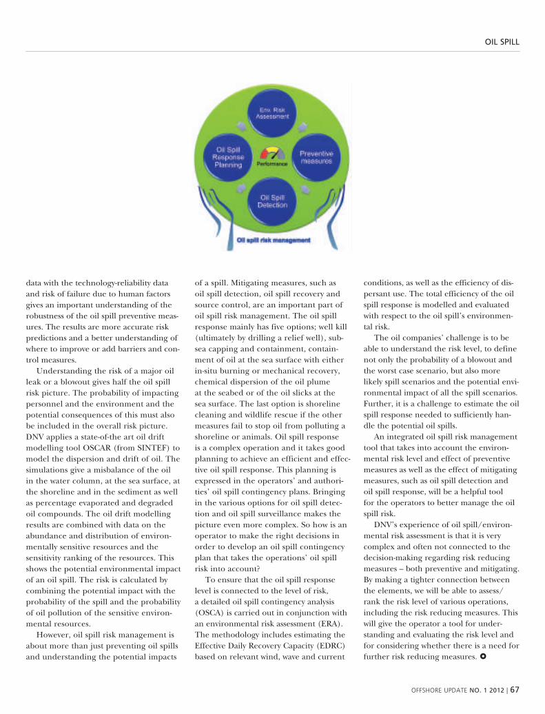
oFFshore uPDate NO. 1 2012 | 67
Oil spill
data with the technology-reliability data and risk of failure due to human factors gives an important understanding of the robustness of the oil spill preventive meas-ures. the results are more accurate risk predictions and a better understanding of where to improve or add barriers and con-trol measures.
understanding the risk of a major oil leak or a blowout gives half the oil spill risk picture. the probability of impacting personnel and the environment and the potential consequences of this must also be included in the overall risk picture. dnv applies a state-of-the art oil drift modelling tool oscar (from sinteF) to model the dispersion and drift of oil. the simulations give a misbalance of the oil in the water column, at the sea surface, at the shoreline and in the sediment as well as percentage evaporated and degraded oil compounds. the oil drift modelling results are combined with data on the abundance and distribution of environ-mentally sensitive resources and the sensitivity ranking of the resources. this shows the potential environmental impact of an oil spill. the risk is calculated by combining the potential impact with the probability of the spill and the probability of oil pollution of the sensitive environ-mental resources.
however, oil spill risk management is about more than just preventing oil spills and understanding the potential impacts
of a spill. mitigating measures, such as oil spill detection, oil spill recovery and source control, are an important part of oil spill risk management. the oil spill response mainly has five options; well kill (ultimately by drilling a relief well), sub-sea capping and containment, contain-ment of oil at the sea surface with either in-situ burning or mechanical recovery, chemical dispersion of the oil plume at the seabed or of the oil slicks at the sea surface. the last option is shoreline cleaning and wildlife rescue if the other measures fail to stop oil from polluting a shoreline or animals. oil spill response is a complex operation and it takes good planning to achieve an efficient and effec-tive oil spill response. this planning is expressed in the operators’ and authori-ties’ oil spill contingency plans. bringing in the various options for oil spill detec-tion and oil spill surveillance makes the picture even more complex. so how is an operator to make the right decisions in order to develop an oil spill contingency plan that takes the operations’ oil spill risk into account?
to ensure that the oil spill response level is connected to the level of risk, a detailed oil spill contingency analysis (osca) is carried out in conjunction with an environmental risk assessment (era). the methodology includes estimating the effective daily recovery capacity (edrc) based on relevant wind, wave and current
conditions, as well as the efficiency of dis-persant use. the total efficiency of the oil spill response is modelled and evaluated with respect to the oil spill’s environmen-tal risk.
the oil companies’ challenge is to be able to understand the risk level, to define not only the probability of a blowout and the worst case scenario, but also more likely spill scenarios and the potential envi-ronmental impact of all the spill scenarios. Further, it is a challenge to estimate the oil spill response needed to sufficiently han-dle the potential oil spills.
an integrated oil spill risk management tool that takes into account the environ-mental risk level and effect of preventive measures as well as the effect of mitigating measures, such as oil spill detection and oil spill response, will be a helpful tool for the operators to better manage the oil spill risk.
dnv’s experience of oil spill/environ-mental risk assessment is that it is very complex and often not connected to the decision-making regarding risk reducing measures – both preventive and mitigating. by making a tighter connection between the elements, we will be able to assess/rank the risk level of various operations, including the risk reducing measures. this will give the operator a tool for under-standing and evaluating the risk level and for considering whether there is a need for further risk reducing measures.

68 | oFFshore uPDate NO. 1 2012
OFFshOre saFety
making sems – enhancing
offshore safety in north america
Following the macondo incident in the gulf of mexico in april 2010, the us authorities determined that there was a need for
further regulations aimed at enhancing safety and environmental standards. this resulted in the quick promulgation of sems
regulations – a systematic approach to managing offshore safety.
teXt: rIcHIE MacTaGGarT
in november 2011, the new safety and environmental management systems (sems) regulations came into force on the us outer continental shelf (ocs). man-aged under the auspices of the bureau of ocean energy management (boem) and bureau of safety and environmental enforcement (bsee), the new require-ments are intended to enhance offshore safety and environmental standards.
as it now stands, sems’ latest itera-tion requirements are the result of a suc-cession of developments to extend the regulations applicable to the us offshore industry. boem and bsee were created in october 2011 out of an earlier organi-sation, boemre. this organisation’s predecessor, the minerals management services (mms), originally introduced sems as a recommended practice for operators back in 1990. Following this, in 1994, mms endorsed the american petroleum institute rp 75, recommended practice for the development of a safety and environmental management program for offshore operations and Facilities. rp 75 was updated in July 1998 to focus more
on contract operations, including opera-tions on mobile offshore drilling units. the major difference in sems now is that it is mandatory, rather than optional, as it was before.
these new regulations require offshore operators to maintain comprehensive safety and environmental programmes to strengthen operational safety and reduce the risk of human error. as part of the new requirements, all operators are required to develop, implement and main-tain a sems programme.
cheryl stahl, head of hse, risk man-agement solutions, dnv houston, states: “sems is a requirement that, in general, requires offshore operators to have cer-tain documentation and define roles and responsibilities. dnv intends to become an approved third-party auditor for sems. in addition, during a sems audit, dnv can gather additional information and highlight potential areas for improve-ment.” dnv can provide benchmarking in addition to the sems audit services, add-ing value to what will eventually become a routine service.
THE rOLE OF SEMS according to bsee, the four primary sems objectives are to: ■■ Focus attention on the influences and effects that human error and poor organisation have on accidents;
■■ continuously improve the offshore industry’s safety and environmental records;
■■ encourage the use of performance-based operating practices; and
■■ collaborate with industry in efforts that promote the public interests of off-shore worker safety and environmental protection.
bsee also states that sems is a regulation for coordinating offshore continental shelf (ocs) oil and gas operations in relation to worker safety and pollution control. bsee has determined that ocs operators must use sems as the foundation for the way they undertake their offshore business.
sems regulations became effective in november 2010 and operators were required to implement a programme by 15 november 2011. the regulations apply to all ocs oil & gas and sulphur
oFFshore uPDate NO. 1 2012 | 69
OFFshOre saFety
operations and the facilities under bsse jurisdiction, including drilling, produc-tion, construction, well workover, well completion, well servicing and doi pipe-line activities.
SEMS II Following the implementation of sems, us regulators sought to include a number of new proposals that were not covered in the original version. the sems rules were released quickly following the macondo incident and there was no pub-lic comment period. however, the next stage, sems ii, represents regulators’ latest thinking, taking into account stakeholder opinion that was solicited over a period of months. its formal title is: 30 cFr part 250. oil and gas and sulphur operations in the outer continental shelf – revisions to safety and environmental management sys-tems. it is often referred to as “sems ii”.
the closing date for comments on sems ii was 14 november 2011 and sems ii is expected to come into force in late 2012.
major elements of sems ii focus on the following new or expanded items:
■■ stop work authority ■■ ultimate work authority ■■ employee participation in sems programme development and implementation
■■ reporting of unsafe working conditions ■■ required use of independent third-party auditors
■■ additional requirements related to Job safety analyses
boem states that they believe “these new requirements will further reduce the likeli-hood of accidents, injuries, and spills in connection with ocs activities … by requir-ing ocs operators to specifically address issues associated with human behavior as it applies to their sems program.”
LEarNING THE rOPES now that sems is in place, there are likely to be teeth-ing troubles, at least in the short-term, as operators and contractors learn to under-stand how the bsee and third-party audi-tors will construe sems requirements. For example, international oil companies have well-developed management systems in place that generally conform to the sems requirements in practice, but often have differences in the auditable details. this may create major challenges. the general practice of such companies is to map their existing global management systems to the sems requirements and label them as “a sems programme.” however, their existing audit programmes must now be supplemented with sems audits that meet particular requirements.
in contrast, small or new operators
may have relatively nascent management systems that are growing with their opera-tions. when using contractors with mature management systems, they have a choice: they can label their system as their sems, or they can review the contractor’s sys-tems for conformance to the new sems requirements and adopt them as their own sems programme.
dnv can assist with bridging documen-tation and help operators and contractors find practical approaches that are execut-able and auditable. another area in which dnv can help is with communication links: key interfaces between operators and contractors. under sems, operators need to ensure adequate processes, documenta-tion and personnel knowledge, even for contractor personnel. in addition, dnv can provide services that supplement exist-ing mechanical integrity documentation to help an operator achieve the desired level of documentation.
cONcLuSION as stahl concludes. “there is no doubt that sems is a significant development for the offshore industry, with the express aim of making it a safer one. the task of companies is to under-stand what is needed to meet sems’ still-evolving requirements for operations in the us ocs.
in this respect, dnv is able to provide training on sems topics, such as risk assessment, safety culture, human factors, mechanical integrity and environmental risks. this is in addition to our role as a third-party auditor and benchmarking frontrunner.”
whO are bOeM aND bsee?on 1 october 2011, the Bureau of ocean energy management, regulation and enforcement (Boemre), formerly the minerals management service (mms), was replaced by the Bureau of ocean energy management (Boem) and the Bureau of safety and environmental enforcement (Bsee) as part of a major reorganisation.
Boem manages the exploration and development of the nation’s offshore resources. it seeks to appropriately balance economic development, energy independence and environmental protection through oil and gas leases, renewable energy development and environmental reviews and studies.
Bsee is responsible for the safety and environmental oversight of offshore oil and gas operations, including permits and inspections. its functions include the development and enforcement of safety and environmental regulations, permitting offshore exploration, development and production, inspections, offshore regulatory programmes, oil spill response and newly formed training and environmental compliance programmes.
Phot
o: g
etty
imag
es

70 | oFFshore uPDate NO. 1 2012
vatteNFall
dnv acquires vattenfall shares in stri
Dnv acquires vattenfall’s shares in stri to expand its presence in the power transmission sector.
“the purchase of 12.5% shares in stri (swedish transmission research institute) is a natural step in our drive to support both the electrification of the oil and gas industry, as well as the integration of renewable energy and the large invest-ments in the power transmission sector,” says kjell eriksson, director of the energy programme in dnv research and inno-vation. “we have known about stri for many years and started a cooperation agreement in June 2011. our joint service offering gives us the opportunity to pro-vide integrated solutions to our customers and meet the growing demand in the mar-ket place.”
according to mr eriksson, the electrifi-cation of both conventional offshore plat-forms and subsea oil and gas installations, and the growth in offshore wind energy are the main drivers behind the collabora-tion with stri. both drivers will require new technical and operational solutions to power transmission he says.
stri is a specialist consultancy firm providing advanced studies of high voltage power transmission systems and accredited high voltage testing. “by combining stri’s knowledge in power systems with dnv’s risk management expertise in offshore installations, we can contribute to setting new, smart demands to what is needed to develop the technology and how to make it robust and reliable enough to transmit large amounts of electricity offshore,” adds mr eriksson.
“vattenfall’s use of stri’s services has declined over the years and we therefore see less of a need to be a partner,” says karl bergman, vice president, research
and development at vattenfall. “the coop-eration has been very fruitful, but as our needs have changed, it is now a good time to liquidate our holdings in stri. we will certainly continue working with stri but as an ordinary customer.”
“since stri was founded we have had a very interesting and close collaboration with vattenfall covering a large number of investigations and r&d projects. it has been a very exciting journey and we are looking forward to keep our good relations and continue our businesses with vatten-fall. with dnv as a shareholder and busi-ness partner, the successful development of stri adds further opportunities for the future. since our cooperation with dnv
started a year ago, it has become very clear to me that our common resources offer very powerful services to the market,” says dan wikström, stri president, and adds, “dnv is most welcome as a new share-holder in stri and it will be very exciting to further develop our cooperation.”
in december last year, dnv obtained a controlling stake in netherlands headquar-tered kema, the global energy consulting, testing and certification company as part of a push to expand its presence in the power generation, transmission and distri-bution sectors. the acquisition of vatten-fall’s shares in stri will further strengthen dnv’s position in power systems, particu-larly in the nordic countries.
›› kjell eriksson at Dnv and Jörgen Josefsson senior advisor at vattenfall.
Phot
o: D
nv
press release, DateD
March 30, 2012

oFFshore uPDate NO. 1 2012 | 71
the pOwer tO explOre New FrONtiers
tomorrow’s oil and gas production will increasingly take place at greater water depths, in harsher envi-ronments and remote locations. Only by pushing the technology envelope can we make many of these new fields accessible at acceptable costs and risks. at the same time, future hydrocarbon occur-rences will increasingly be located in more fragile environments, necessitating a high degree of relia-bility and safe operations. we will likely see stricter regulatory frameworks demanding transparent and environmentally sustainable operations.
DNv has built a broad competence base in subsea technology. we provide services ranging from con-cept evaluation, through product development to manufacturing control and follow-up. we also fo-cus on installation and operational maintenance. when qualifying new technologies, our engineers combine a deep-rooted technology competence with a systematic risk-based approach, so that reg-ulators, operators and industry contractors can pro-ceed with greater confidence in their concept se-lection, performance and investment.
EXPLORE NEW FRONTIERS
THE POWERTO

globalpresence
Dnv is a global provider of services for managing risk, helping customers to safely and responsibly improve their business performance. Dnv is an independent foundation with presence in more than 100 countries.