12 reservoir technolgy august 2015 - universitetet … engineering •fluid types •how is oil...
TRANSCRIPT

12 Reservoir technolgy August 2015
2015-08-24 Classification: Internal

Reservoir Engineering
• Fluid types
• How is oil produced
• Fluid flow in porous media
• Drainage strategies
• Well solutions and IOR toolbox
Classifi
cation:
Internal
2012-
05-03
2
Reservoir Engineering
• Fluid types
• How is oil produced
• Fluid flow in porous media
• Drainage strategies
• Well solutions and IOR toolbox
Classifi
cation:
Internal
2012-
05-03
3

HC are a complex mixture of:
• Methane CH4 C1
• Ethane C2H6 C2
• Propane C3H8 C3
• Butane C4H10 C4
• Pentane … C5
• Hexane… … C6
• Heptane … C7
• Octane … C8
• … C9
• and the heavier … C10+
• and contaminants N2, CO2, H2S
HydroCarbons or just “Oil” and “Gas”?
• Oil or Gas depends on chemistry and physics
− To answer we need phase diagrams:
“p vs. T” and “p vs. V”
Classifi
cation:
Internal
2012-
05-03
4

Hydrocarbon “names” and Sales products
Methane Ethane Propane Butane Pentane Hexane Heptane Octane Nonane Decane … … …
Oil stable
Oil unstable
stable Condensate
LPG
NGL
Rich gas
Sales gas and LNG
C1 C2 C3 C4 C5 C6 C7 C8 C9 C10 C11 C12 C13 …
C10+
Classifi
cation:
Internal
2012-
05-03
5

Hydrocarbons (oil/gas) From reservoir to surface
Classifi
cation:
Internal
2012-
07-09
6
RESERVOIR SURFACE
GAS
OIL
+ NGL/CONDENSATE
+ DISSOLVED GAS
EXPANSION
SHRINKAGE
∆p
∆p

Reservoir Engineering
• Fluid types
• How is oil produced
• Fluid flow in porous media
• Drainage strategies
• Well solutions and IOR toolbox
Classifi
cation:
Internal
2012-
05-03
7

How is Oil Produced?
• Drill a well and perforate
• Start producing by opening up the well head choke
• Oil flows into the well and to the surface due to “excess energy” in the reservoir
− the bottom hole pressure (pBH) is higher than the well head pressure (pWH) + the fluid column “weight” (ρgH) i.e. pBH – pWH > ρgH (+ pfriction)
− For some reservoirs artificial lift is “necessary”
• Gas lift (reduce ρgH)
• Downhole pump (increase pBH)
• When the well flows there is also a pressure drop from the reservoir and into the well (drawdown), pr – pBH > 0
Reservoir Pressure: pr
Bottom Hole pressure: pBH
Well Head Pressure: pWH
Classifi
cation:
Internal
2012-
05-03
8
H
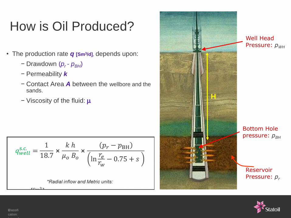
How is Oil Produced?
• The production rate q [Sm3/d], depends upon:
− Drawdown (pr - pBH)
− Permeability k
− Contact Area A between the wellbore and the sands.
− Viscosity of the fluid: m
Reservoir Pressure: pr
Bottom Hole pressure: pBH
Well Head Pressure: pWH
Classifi
cation:
Internal
2012-
05-03
9
H

Reservoir Engineering
• Fluid types
• How is oil produced
• Fluid flow in porous media
• Drainage strategies
• Well solutions and IOR toolbox
Classifi
cation:
Internal
2012-
05-03
10
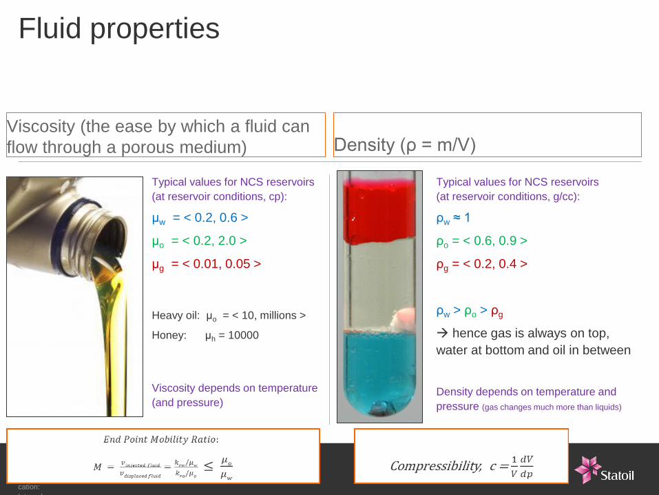
Fluid properties
Viscosity (the ease by which a fluid can
flow through a porous medium)
Typical values for NCS reservoirs
(at reservoir conditions, cp):
μw = < 0.2, 0.6 >
μo = < 0.2, 2.0 >
μg = < 0.01, 0.05 >
Heavy oil: μo = < 10, millions >
Honey: μh = 10000
Viscosity depends on temperature
(and pressure)
Density (ρ = m/V)
Typical values for NCS reservoirs
(at reservoir conditions, g/cc):
ρw ≈ 1
ρo = < 0.6, 0.9 >
ρg = < 0.2, 0.4 >
ρw > ρo > ρg
hence gas is always on top,
water at bottom and oil in between
Density depends on temperature and
pressure (gas changes much more than liquids)
Classifi
cation:
Internal
2012-
05-03
11
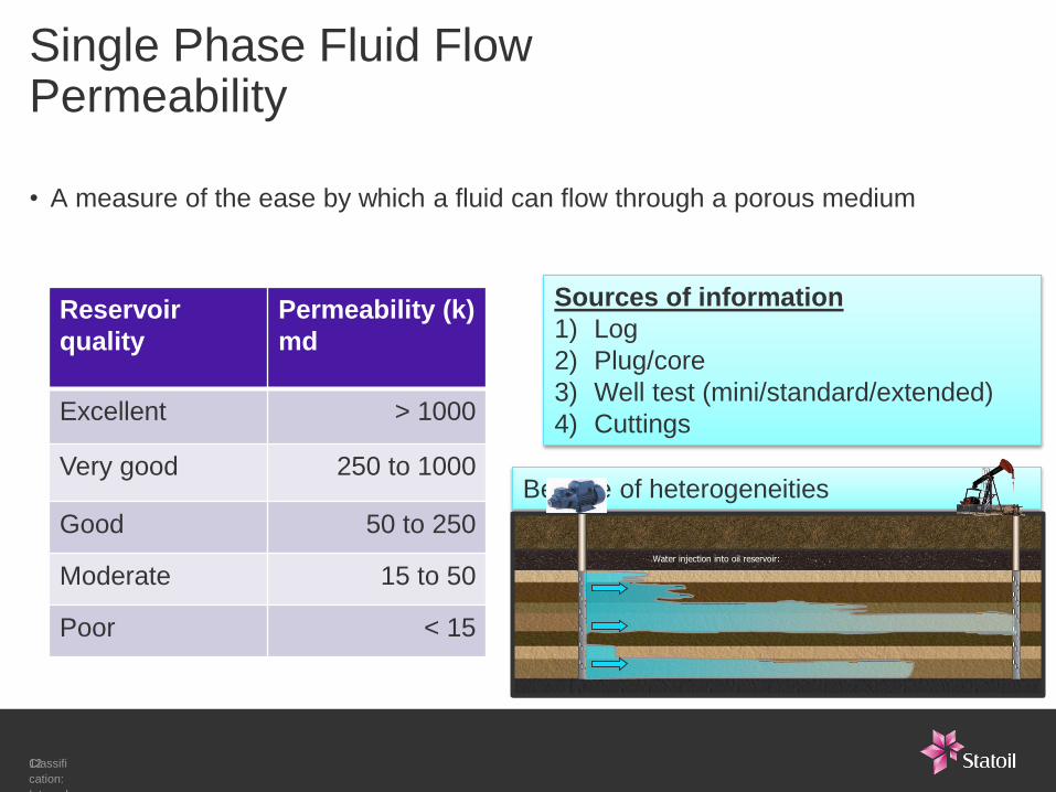
Single Phase Fluid Flow Permeability
• A measure of the ease by which a fluid can flow through a porous medium
Reservoir
quality
Permeability (k)
md
Excellent > 1000
Very good 250 to 1000
Good 50 to 250
Moderate 15 to 50
Poor < 15
Classifi
cation:
Internal
2012-
05-03
12
Sources of information
1) Log
2) Plug/core
3) Well test (mini/standard/extended)
4) Cuttings
Beware of heterogeneities
Water injection into oil reservoir:

Classifi
cation:
Internal
2011-
09-05
Two Phase Fluid Flow Relative permeability
a
1 . 0
0 . 8
0 . 6
0 . 4
0 . 2
0 . 0
0 . 2 0 . 4 0 . 6 0 . 8 1.0 0 . 0
kro krw
Ko,eff = K * kro
Kw,eff = K * krw
Measured on core plugs
(or use analogue data)
Sorw: lowest possible value
of mobile oil
Typical values of Sorw :
< 0.15, 0.25 >
Water displaces oil
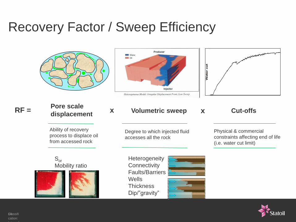
Recovery Factor / Sweep Efficiency
Classifi
cation:
Internal
2012-
05-03
14
RF = Pore scale
displacement
Ability of recovery
process to displace oil
from accessed rock
Volumetric sweep x
Degree to which injected fluid
accesses all the rock
Cut-offs x
Physical & commercial
constraints affecting end of life
(i.e. water cut limit)
Sor
Mobility ratio
Heterogeneity
Connectivity
Faults/Barriers
Wells
Thickness
Dip/”gravity”
Reservoir Engineering
• Fluid types
• How is oil produced
• Fluid flow in porous media
• Drainage strategies
• Well solutions and IOR toolbox
Classifi
cation:
Internal
2012-
05-03
15

16 Classification: Internal 2013-02-21
‘PRIMARY RECOVERY’
Pressure depletion; no injection at all.
NATURAL DRIVE
‘SECONDARY RECOVERY’
Injection of fluids for pressure maintanance.
PHYSICAL DRIVE
‘TERTIARY RECOVERY’
Injection of fluids designed to further improve recovery; “advanced recovery methods”.
DESIGN DRIVE
Natural depletion
ENHANCED OIL RECOVERY (EOR) All advanced recovery methods
IMPROVED OIL RECOVERY (IOR) All measures beyond current plans to improve expected oil/gas recovery. Can include all mechanisms.
Water injection
Gas injection
Thermal
Chemical
Miscible gas
WAG
Other
Drainage strategy
Find the best suited mechanism
for optimal resource exploitation
Drainage Strategy / Drive mechanism
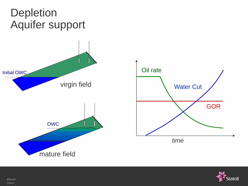
mature field
OWC
Depletion Aquifer support
Initial OWC
virgin field
Oil rate
Water Cut
GOR
time
Classifi
cation:
Internal
2012-
05-03
17
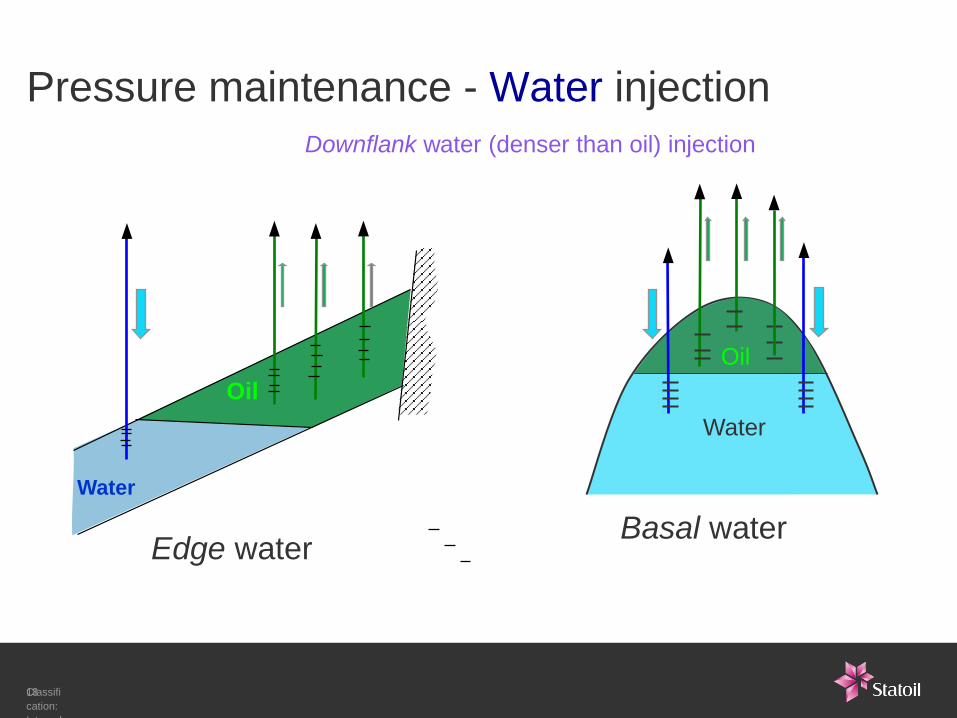
Pressure maintenance - Water injection
Water
Oil
Water
Oil
Basal water Edge water
Downflank water (denser than oil) injection
Classifi
cation:
Internal
2012-
05-03
18
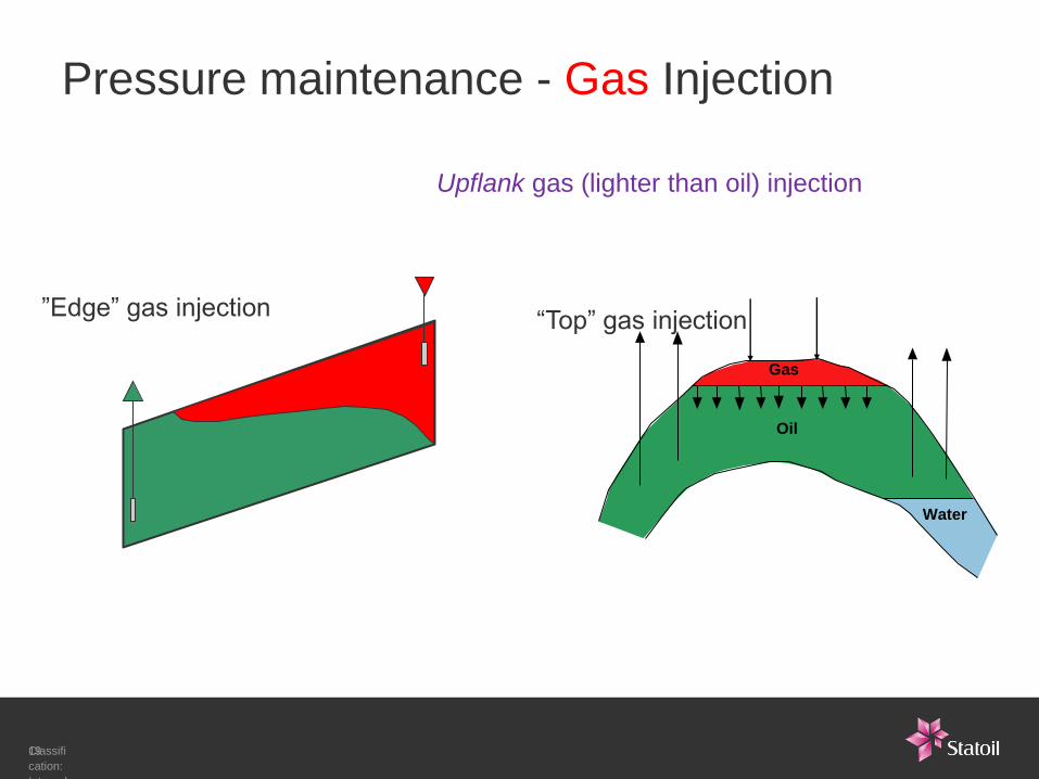
Pressure maintenance - Gas Injection
“Top” gas injection ”Edge” gas injection
Upflank gas (lighter than oil) injection
Classifi
cation:
Internal
2012-
05-03
19
Gas
Water
Oil

Rules of thumb - The Big Picture
Recovery Factor Low Medium High
Oil field – by depletion and without
aquifer support. (a)
10% 15% 20%
Oil field – by efficient Water or Gas
injection or strong aquifer support. (a)
30% 50% 60%
Gas field - by depletion. (b)
60% 70% 80%
Classifi
cation:
Internal
2012-
05-03
20
UR = STOOIP * RF
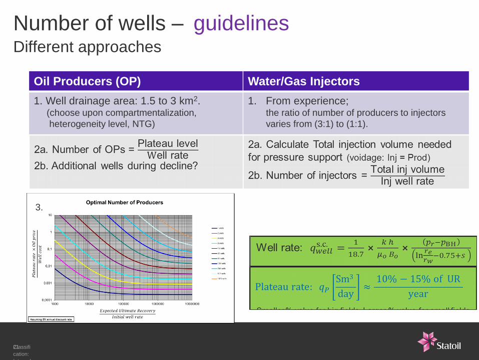
Number of wells – guidelines Different approaches
Oil Producers (OP) Water/Gas Injectors
1. Well drainage area: 1.5 to 3 km2. (choose upon compartmentalization,
heterogeneity level, NTG)
1. From experience; the ratio of number of producers to injectors
varies from (3:1) to (1:1).
Classifi
cation:
Internal
2012-
05-03
21
3.

Reservoir Engineering
• Fluid types
• Fluid flow in porous media
• Drainage strategy
• Well solutions and IOR toolbox
Classifi
cation:
Internal
2012-
05-03
22
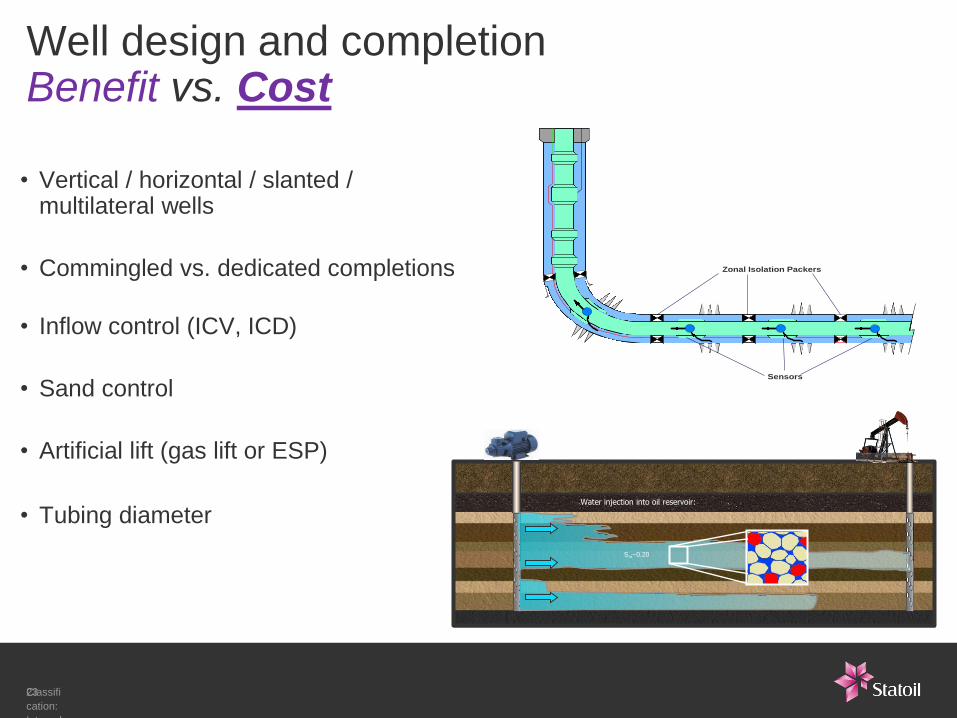
Well design and completion Benefit vs. Cost
• Vertical / horizontal / slanted / multilateral wells
• Commingled vs. dedicated completions
• Inflow control (ICV, ICD)
• Sand control
• Artificial lift (gas lift or ESP)
• Tubing diameter
Sensors
Zonal Isolation Packers
Classifi
cation:
Internal
2012-
05-03
23
Water injection into oil reservoir:
Sor~0.20

Increased oil recovery
Statoil’s toolbox in the whole value chain
Platform technology • Low pressure production
• Debottlenecking
Subsea technology • Compression
• Boosting
Drilling and well • Advanced wells
• Well Interventions
• Standardised well solutions
Reservoir management • Conventional and advanced
recovery methods
• Geophysical reservoir
monitoring
• Mapping and modeling of
complex reservoir formations

Reservoir Engineering Toolbox Simulation models versus Analytical methods
• Reservoir simulation models may help identifying the number of wells required,
the optimal completion of wells, the present and future needs for artificial lift, and
the expected production of oil, water and gas.
− In Statoil there is a requirement to have a reservoir simulation model at DG2 level, but
most projects have a simulation model at DG1 or earlier.
• Analytical methods generally cannot capture all the details of the given reservoir
or process, but are fast and at times, sufficiently reliable.
− In modern reservoir engineering, they are generally used as screening or preliminary
evaluation tools.
− Analytical methods are especially suitable for potential assets evaluation when the data
are limited and the time is critical.
Classif
ication
:
Intern
al
2013-
08-28
25

Classification: Internal 2013-07-12 26
Petrophysics
reservoir properties,
fluid saturations, etc.
Seismic interpretation
structure map, faults,
etc.
Well design
well design, drilling
schedule, lift curves
Economics
oil price & cost
assumptions
Facilities design
production, process
& export design
Uncertainty analysis
static & dynamic
uncertainty analysis
Reservoir engineering
simulations – grid and model effects
drainage strategy, # wells, well types, position
Geomodeling
reservoir properties,
pay, continuity, etc.
Calibration
field observations,
production data, etc.
Outcome
production profiles + uncertainty
project economics - for investment decision
- The subsurface workflow - Security
Classificati
on: Internal
- Status:
Draft
Cooperation between the
disciplines is the only way to
make the right decisions.
Communication is the key to
success!

2015-08-24 27 Classification: Internal

Presentation title
Presenters name
Presenters title
E-mail address ……@statoil.com
Tel: +4700000000 www.statoil.com
2015-08-24 28 Classification: Internal