12 poster - worldradiohistory.com
TRANSCRIPT


2 D-I-Y RADIO January-February 1996
using a 77m high tower tosupport their 3.5MHz loopantenna. Emma Con-stantine, 2E1BVJ, tells usall about it.
12 POSTERAMATEUR RADIO &CIRCUIT SYMBOLSElectronic circuit diagramsuse a range of symbolswhich are recognised world-wide. With this chart, youcan decode them.
14 CONSTRUCTIONAN AUDIOCONTINUITY TESTERRobert Snary, G4OBE,describes how to test forfaults with this handy littlebleeper.
16 ON THE AIR2’S COMPANY/LOGBOOK/PREFIXESOur regular columns for thelistener and the Novicelicensee. Plus everythingyou need to know about the12 metre band.
3 NEWSGuides & Scouts on the Air,Observing Amateur Radio,Future of Licensing, SchoolSpace Link-up, RSGB Do-nation to Satellite Project.
5 CONSTRUCTIONSW RECEIVERPRESELECTORSteve Ortmayer, G4RAW,explains how to improve theperformance of your short-wave receiver when usedwith a short antenna.
7 HAM FACTSRESISTORS ANDCAPACITORSTo go with the ComponentsPoster in our centre pages,we provide some useful de-tails on a few of the mostcommon radio parts.
8 THE WHATS, WHYSAND WHEREFORESINTRODUCINGTRANSFORMERSJohn Case, GW4HWR, ex-plains all about transform-ers and how they work.
10 NEWS FEATUREA TOWERINGSUCCESSRishworth School and Hali-fax radio clubs had a day out
Managing Editor: Mike Dennison; Production Editor: Jennifer Crocker; Technical Editor: Peter Dodd; Technical Illustrator: Bob Ryan; News Ed: Steve Lowe; Prod Asst: Wai-Yee Man; Secretary: Samantha RalphD-i-Y RADIO is published six times a year by the Radio Society of Great Britain, Lambda House, Cranborne Road, Potters Bar, Herts. Filmset by JJ Typographics Ltd. Printed by Southernprint(Web Offset) Ltd. © Radio Society of Great Britain, 1996. All rights reserved. No part of this publication may be reproduced, stored in a retrieval system, or transmitted, in any form or by any means,electronic, mechanical, photocopying, recording or otherwise, without the prior written permission of the RSGB. All reasonable precautions are taken by the Radio Society to ensure that the adviceand data given to our readers are reliable. We cannot however, guarantee it and we cannot accept legal responsibility for it. Prices quoted are those current as we go to press. ISSN No: 0959-843X.
COVER PICTURE:Emma, 2E1BVJ, and Matthew,2E1BOO, admire the view - and theradio ‘take-off’ - from the top of theWainhouse Tower. Feature: page 10.Photograph: G3UGF.
Japanese Girl Scouts: Front Row (l to r) - Misaki, 7K4GFJ; Marie, 7K2LQA. BackRow - Izumi, 7K1OUO; Jinbo, 7L2LQD; Sachiko, 7M1HDU. They are picturedwith Yoko and Taizo Arakawa, JG3FAR and JA3AER/GW0RTA.
Radio components are the subject ofour poster and Ham Facts.
18 NEWS FEATUREJOIN THE BANDWAGONSeveral years ago PeterWood, G0HWQ, caught theradio bug. He describes hisfirst receiver.
20 CONSTRUCTIONEXPERIMENTAL430MHZ ANTENNAHere’s a novel type of fold-away antenna for the432MHz (70cm) band - arhombic.
22 LETTERS AND DIARY
23 PUZZLE PAGEWIN A COPY OF THEAMATEUR RADIOOPERATING MANUAL
commentTO CELEBRATE the start of anew year, we’ve re-designed thecover of D-i-Y Radio - we hopeyou like it. 1996 should see thelaunch of the Phase 3D amateur
satellite, described in the last edi-tion. It will also mark the lowestpoint of the sunspot cycle. There’seven the possibility of a new ama-teur band being announced. It
should be an interesting year onthe air.
You can now subscribe to D-i-YRadio in three different ways. For those who are not mem-
bers of the RSGB, a subscriptionto D-i-Y Radio costs £9. If you are under 18, you canchoose to join the RSGB HamClubfor just £10. This provides almost
all of the benefits of RSGB mem-bership but with D-i-Y Radio sentto you every two months insteadof the members’ monthly maga-zine Radio Communication.
If you are already an RSGBmember, you can subscribe toD-i-Y Radio for an additional £7.65.
All of these subscriptions comewith a joining pack, and further
information can be found on pages4 and 6 of this edition.
I hope you enjoy this D-i-Y Ra-dio. Have a really good new year,and please keep writing to us and
sending in your photographs.
Mike Dennison, G3XDV
Editor
33333
55555
77777
88888
1010101010
1212121212
1414141414
1616161616
1818181818
2020202020
2323232323
2222222222

3D-I-Y RADIO January-February 1996
NewsRSGB
Guides and Scoutsget on the Air
SCHOOL SPACELINK-UPBELFAST ROYAL Academy’samateur radio club recentlyparticipated in a live radiolink-up with Germanastronaut Thomas Reiter,DP0MIR, during his 135-daymission on board theRussian Mir space station.The school’s 2m equipmentwas thoroughly checked outin preparation for the FMsemi-duplex contact and afull turn-out of club memberswitnessed the event.Jonathan Chin, GI7NIL,asked about the prepar-ations for the visit from theAtlantis shuttle crew andThomas described thegreetings they would receiveon their arrival. Thomas andhis Russian crewmates alsosent greetings to the schooland the city of Belfast.
MEMBERS OFthe Girl ScoutGunma Troop 4Amateur Radio
Club in Tokyo, Japan, willbe operating as JL1ZDLduring Thinking Day on theAir (TDOTA), which this yearis on 24 and 25 February.They hope to contact GirlGuide stations in the UK, soif you are involved with aspecial event station forTDOTA please look out forthem. The girls are shown(opposite) with Taizo(GW0RTA / JA3AER) andYoko (JG3FAR) Arakawa,who met them during arecent visit to Japan.
Back in October, MrsBetty Clay, daughter of theScouting movement’sfounder, Lord Baden Powell,visited a Jamboree on theAir station operated bymembers of the Tauntonand District Amateur RadioClub. Mrs Clay sent agreetings message fromGB2TWH, which wasoperated on behalf of theTaunton and District Scouts.She said that althoughScouts and Guides abroadmay be different toourselves, through Scoutingthere are many similarities.All Scouts share the sameaim - to improve their talentsand skills so that they canhelp other people to lead ahappier life.
OBSERVING AMATEUR RADIO
FAMOUS TV astronomer Patrick Moore recentlyopened new extensions to the Norman LockyerObservatory at Sidmouth in Devon, thanks to a£125,000 grant from the East Devon District Council.The extensions include a planetarium seating 60people and two new radio rooms equipped with HFand VHF demonstration stations. A permanent specialevent callsign, GB2NLO, has been issued to thestation.
The observatory was set up in 1913, and radio hasbeen used there ever since: Marconi himself was anearly visitor. You can also visit the observatory onopen days and certain nights throughout the year.Arrangements for group visits can be made bycontacting the Secretary on 01395 568591.
Patrick Moore meets F J Gregory, G3AQM, of the Norman LockyerObservatory Amateur Radio Group in the new HF room at GB2NLO.
THE FUTURE OF LICENSINGTHE 1995 WORLD Radio Conference (WRC) discussedthe proposal to delete RR2735, the international regulationrequiring national administrations to test for proficiency inMorse code before allowing amateurs to operate on the HFbands (ie below 30MHz). It was agreed that the matter willbe on the agenda at WRC 1999, which will give sufficienttime to obtain a considered opinion on the matter fromamateurs throughout the world.
As a result, the RSGB is to carry out a survey to find outamateurs’ views on the qualifications and licensing structurenecessary for the UK Amateur Service. RSGB Councilrecently approved a recommendation that the Society’sLicensing Advisory Committee should supervise the surveywhich will cover all interested parties, whether members ofthe RSGB or not.
PLEASE NOTE that theRSGB HQ Annual Open Daywill be on Saturday 4 May,and not as indicated in the1996 calendar published inthe November - December1995 D-i-Y Radio.
RSGB DONATION TOSATELLITE PROJECTTHE 1995 President, CliveTrotman, GW4YKL, recentlypresented a cheque for£25,000 on behalf of theRSGB to Ron Broadbent,G3AAJ, for the AMSATPhase 3D satellite project.Ron thanked the RSGB forits support and said thatAMSAT-UK had alreadycontributed over £110,000towards the project. Moredetails on Phase 3D werepublished in the November -December 1995 D-i-YRadio. The satellite is nowwell on the way tocompletion, and is due to belaunched by an Ariane rocketfrom French Guiana in SouthAmerica towards the end ofthis year.
AS FROM 1 January, thenew address for the HQ ofISWL is: Mrs M H Carrington,G0WDM, Hon SecretaryISWL, 3 Bromyard Drive,Chellaston, Derby DE731PF.

Advertisement

5D-I-Y RADIO January-February 1996
Construction FeatureRSGB
By SteveOrtmayer,G4RAW
SW Receiver Pre-SelectorA PRE-SELECTORis a tuned radiofrequency amplifier
that is used between theantenna and the receiver’santenna socket.
WHY USE A PRE-SELECTOR?THERE ARE SEVERALreasons why a pre-selector mayprove to be beneficial.
To increase the signal levelbecause the antenna in useis inefficient.
To increase the sensitivityof an old receiver.
To increase the signal-to-noise ratio of the receivedsignal, because thereceiver and antenna arelocated in an electricallynoisy environment.
The pre-selector describedhere uses a tuned circuit with
COMPONENTSResistors - all 1/4 Watt carbon film resistorsR1 270RR2 15RR3 100R
CapacitorsC1, C2 100nF disc ceramic capacitorsVC1 250/250pF polyvaricon capacitor
InductorsL1, L2 19t 26swg on T.50.6 toroid tap
L1 4 turns from ground end; L1Aand L2A 3 turns over L1 and L2
SemiconductorsTR1 MPF102 FET
Additional ItemsAluminium box 12 x 9 x 3cmBattery and snap PP3 9VSW1 ON/OFF SwitchPhono sockets or similar for input and output
an FET amplifier in a ‘groundedgate’ mode. The reason for thisarrangement, instead of thenormal way of inputting thesignal to the gate of the FETis for stability. An amplifierwith a tuned circuit at boththe input and the output hasa tendency to oscillatebecause of the feedbackfrom the one tuned circuitto the other.
The grounded gate FETdoes not give much gain butit is stable. The pre- selectortunes the 7, 10, 14, 18, 21, 24,and 28MHz amateur bands aswell as the broadcast bands inbetween.
CONSTRUCTIONTHE CIRCUIT IS constructedon plain perforated board withthe components pushedthrough the holes in the boardand soldered together under-neath to complete the circuit.Solder tags are used for anearth wire and when bolted tothe case with stand-offs willearth the board.
Fig 2: HF pre-selector, front panel layout.
Fig 1: HF pre-selector, circuit diagram.
C RSGB DY256
2824
2118
14
10
7.5
Tune
Rx Preamp
ON
C RSGB DY257

6 D-I-Y RADIO January-February 1996
Construction FeatureRSGB
The board is mounted ina small aluminium box witha battery and an on/offswitch. Sockets of yourchoice are used to connectthe antenna and the receiver.The twin polyvaricon capacitorcan be fitted with a pointerknob and a scale can bemade to locate the bandscovered.
When complete, check thewiring and connect to the lowimpedance (coax) socket of thereceiver. Tune VC1 and a boostin the signal should be heard.Tune to the bands coveredand mark the scale forreference.
C RSGB DY258
Fig 3: HF pre-selector, component layout.
Advertisement

7D-I-Y RADIO January-February 1996
Ham FactsRSGB
Resistors and CapacitorsNO MATTER whatthe circuit is, thechances are it will
contain resistors and capacitors.These two components are themost widely-used in electronics.Here we look at different typesof resistors and capacitors inmore detail.
FIXED RESISTORSTHESE ARE AMONG the mostreliable components if correctlyselected for the purpose. As thename implies, they resist thepassage of current and in factthe unit ‘ohm’ is really the‘voltage per amp’. For manyyears resistors were made of amoulded mixture of carbon andbinder, either painted orenclosed in an insulating tube.
Tubes of carbon compositionin various diameters withmetallised ends are made forhigh-wattage dissipation. Thesemay bear the trade nameMorganite, and are suitable forRF loads. Metal-film resistorsare more stable, less noisy andmore reliable than carbon.
For higher powers, wire-wound resistors are used. Morereliable ones are wound on aceramic substrate protected byvitreous or silicone enamel, andfor greater heat dissipationencased in an aluminium bodywhich can be bolted onto thechassis or heatsink. Wire-wound resistors are of no use atradio frequencies owing to theirinductance.
VARIABLERESISTORSOFTEN A RESISTOR has to bemade variable, either for controlor pre-set adjustment purposes,when it is usually called atrimmer. For versatility, variableresistors are made with amoveable tapping point, and
this arrangementis called apotentiometer ,or ‘pot’ for short.
Carbon comp-osition, cermet,conductive plasticand wirewoundconstruction areall used. Rotarytracks with bothmulti-turn andsingle turn are allavailable, both forpots and trim-mers, in varyingdegrees ofaccuracy. Single-turn rotary pots forvolume controland many otheruses usually turnover 250°, with logand anti-log law as well a linearlaw being available.
FIXEDCAPACITORSCERAMIC CAPACITORS arethe smallest and the loss factoris very low, comparable withsilvered mica, and the valuestays very nearly constant withtemperature, applied voltageand life (stability).
Mica capacitors are largerthan ceramic capacitors for agiven value. Because theygenerally remain stable for longperiods and have low loss theyare used for tuned circuits andfilters. The voltage rating andvalue are normally printed onthe body.
Paper-dielectric capacitorswere once much used, but arenow only found as high-voltagesmoothing capacitors andsuppression capacitors formains use. Paper capacitors arelarge and expensive for a givenvalue, but are very reliable.
Capacitors come in a variety of shapes and sizes.Now turn to ourposter onpages 12/13for more oncomponents
Common values of plasticfilm capacitors range from about1nF (nanofarad) to severalmicrofarads, and can be ratedup to several kilovolts, com-ponents with the higher voltageratings being able to replacepaper capacitors in manyapplications. Tolerance is notusually important as thesecapacitors are unsuitable fortuned circuits but, as they maybe used in resistor-capacitortiming circuits, 5% or better maybe bought for increased cost.The value is marked either bycolour code or printing, alongwith the tolerance and voltagerating.
Electrolytic Capacitors aremuch used for values larger thanabout 1µF (microfarad). Thedielectric is a thin film of oxideon either aluminium or tantalum,and an electrolyte is used tocontact the other plate.
Electrolytics are rated for avoltage at a specified maximumtemperature. At full rating, someelectrolytics have only 1000hours of life. There is always anappreciable leakage current.

8 D-I-Y RADIO January-February 1996
The Whats, Whys, and WhereforesRSGB
By John,GW4HWR,ChairmanRSGB Training& EducationCommittee
Introducing TransformersPLACE A BARmagnet inside acoil then connect a
sensitive milliammeter (a centrereading galvanometer ifpossible) as shown in Fig 1 .The pointer of the meter willremain rock steady on zero, butpull the magnet out of the coiland the pointer will deflect asshown in Fig 2 .
Push the magnet back in andagain the meter will indicateagain but this time the pointerwill move in the oppositedirection. Note that the meteronly indicates current flow whilethe magnet is moving in or outof the coil. This is the principleon which the transformeroperates.
DC AND ACIN ITS SIMPLEST form thetransformer consists of two coilswound either on top of oneanother or side by side. If a DCsupply (such as a battery) isconnected to one coil (the
primary ) the current flowingthrough it will generate amagnetic field but the field willbe stationary and therefore willhave no effect on the other coil(the secondary ) but if a 50HzAC supply is connected insteadof the DC, the magnetic fieldproduced by the primary willvary continuously and an ACvoltage will be generated in thesecondary. Fig 3 .
ENERGYTRANSFERAT DOMESTIC mains freq-uency (50Hz) this transformeris not very efficient and if anattempt were made to drawcurrent from the secondary byconnecting a resistor, thevoltage across the secondarywould fall to zero. This isbecause energy is transferredfrom primary to secondary bymeans of the changingmagnetic field and the fieldproduced by the primary issmall unless the windingcontains a great many turns. A
C RSGB DY247 C RSGB DY248
Fig 1: Galvanometer and coil with stationary magnet. Fig 2: Galvanometer and coil with moving magnet.
Fig 3: Layout of transformer windings.
considerable improve-mentwould occur if an iron core wasintroduced into the coils asshown in Fig 4 because withthe same number of turns inthe primary, the magnetic fieldcreated will be many timesgreater than before.
LINEARRELATIONSHIPFOR BEST RESULTS the coreshould be continuous, that isthe magnetic field is contained
C RSGB DY249

9D-I-Y RADIO January-February 1996
The Whats, Whys, and WhereforesRSGB
wholly in iron and the crosssection of the iron should bethe same for all parts of themagnetic circuit. A core havinga cross section of one squareinch will enable just about 100watts to be transferred fromprimary to secondary. Therelationship is linear so that acore having a cross sectionalarea of 2 square inches will becapable of transferring 200watts and so on.
However there is a serioussnag - the magnetic fieldproduced by the primary currenttreats the lump of iron as avery low resistance secondarywinding which has its endsshorted together. A very highcurrent flows in the iron causingconsiderable heat which wouldeventually result in thetransformer burning up.
EDDY CURRENTSTHESE CURRENTS flowing inthe core are known as eddycurrents and are reduced to avery low level by making theiron non-conductive while stillleaving its magnetic propertyintact. Instead of using a solidlump, the iron is made up byusing a series of thin sheets or
C RSGB DY250 C RSGB DY251
Fig 5: Arrangements of transformerlaminations.
Fig 4: Layout of transformer windings on magnetic core.
laminations each being coatedon one side by an insulatingmaterial. The insulation is oftenin the form of paper, sprayedon in liquid form. This makes iteasy to wind the primary andsecondary and the core isusually assembled after thecoils are wound on a bobbin ,by interleaving Es and Is or Usand Ts. Fig 5 should help tomake this clear.
Another useful figure is thenumber of turns required on thewindings. Again these figuresonly apply to transformers tobe used on an input supply of50Hz. First a figure for the ‘turnsper volt’ is established, it isagain linked to the crosssectional area of the core - 1square inch of core requires 8turns per volt but this time therelationship is in inverseproportion in other words a coreof 2 square inches will requireonly 4 turns per volt. Once the‘turns per volt’ is known the restis easy. For a transformer witha core of 2 square inches (andtherefore 4 turns per volt) aprimary winding which is to beconnected to 240V 50Hzsupply, will need 240 x 4 = 916turns. If the secondary is tosupply 12 volts its winding willneed 12 x 4 = 48 turns.
Finally the size of the wirerequired can be found fromcharts known as copper wiretables together with the windingspace required which will in turndetermine the size of thewinding window as indicated inFig 4.
Advertisement

10 D-I-Y RADIO January-February 1996
News FeatureRSGB
A Towering Successby EmmaConstantine,2E1BVJ
ONCE UPON atime, so the storygoes, two mencourted a beautiful
young lady. The maidenmarried the rich man, to helpher starving family, andalthough he was kind and hebuilt her a beautiful garden, hewas a very jealous man. Somuch so that he constructed awalled garden, so that no mancould see her walking in thegrounds. The poor man neverstopped loving her, and longedto see her again. He eventuallymade his fortune in the clothtrade, owned a mill, and withhis wealth constructed a hugestone tower, so high that hecould see his love from hisroom, at the top.
THE WAINHOUSETOWERIT’S A NICE STORY and thereis some truth in it, but the reality
is that the Wainhouse Tower,all 253 feet of it, is actually aVictorian dyeworks chimney,built in the 1890s, althoughnever used for its originalpurpose. Every year, the Halifaxradio club meets there tocelebrate the exploits of thelegendary local wirelesspioneer, Percy Dennison, 2KD.His adventures would fill a bookand include many radio firsts inthe 1920s, using theWainhouse Tower to supporthis antennas.
Imagine then our delightwhen they offered to letmembers of Rishworth SchoolRadio Club take part in thisannual event, and gave us thechance to use their ‘monster’80m delta loop antenna, almost70m high, over the spring BankHoliday weekend.
Many amateurs spend alifetime getting by and worksome excellent DX with makedo and mend antennas which
have to fit into a pocket sizegarden. However, if you hearany of those big DX signalsbooming in on any of the highfrequency bands, and listen totheir antenna set ups, it justmakes you green with envy.My dad [Richard Constantine,G3UGF - Ed] says “There’s nosubstitute for metal in the sky”when it comes to antennas, butI think that saying is even olderthan he is!
Even though we Noviceoperators enjoy meeting atschool every Saturday morningin term time (yes, we do gothere of our own free will!), therecomes a time when you haveto break out and do somethingdifferent. This was our chanceto experience full-size antennaswith real gain, the kind that arebeyond the dreams of mostamateur operators.
THE CHALLENGEHAVING RECENTLY managed- by the beg, borrow andotherwise obtain method - anHF station, the club was lookingfor a new challenge and achance to use the ‘big rig’ forreal. The club call is G0SQA,which we all say stands for “SillyQuestions Answered” - not badfor a school radio club! Well,SQA number one coming up:
How do you raise an antennaup a tower, 65 metres abovethe ground? Answer: first, yourun up a spiral staircase of morethan 300 steps (I lost count halfway up and ran out of breath),in the dark, then you lowersome 200 metres of rope overthe side with a weight on theend. This blows away in thewind, and doesn’t gostraight down.Then you chasethe end of it
This drawing shows the sheer scale of the Wainhouse Tower and the 80m delta loop aerial used by EmmaConstantine, 2E1BVJ.
C RSGB DY254
11D-I-Y RADIO January-February 1996
News FeatureRSGB
over three fields and agraveyard and drag it back.Once you have wrestled it tothe ground, you smile sweetlyat the strong men of the Halifaxradio club, who sweat andstrain whilst hauling it up intothe air, trying not to tangle orkink the huge triangle ofcopper-coated steel wire,which may cause it to breakbefore you have even calledCQ.
Once up, you have to anchordown the men hanging on toeach of the two bottom corners,before they too blow away orget hauled up the tower by theenthusiastic crew at the top.Communicating by means of70cm handhelds whilst you doall this is an absolute must, asit is too far to shout and far lessdangerous.
DRAW
ING
COUR
TESY
OF
CALD
ERDA
LE C
OUNC
IL
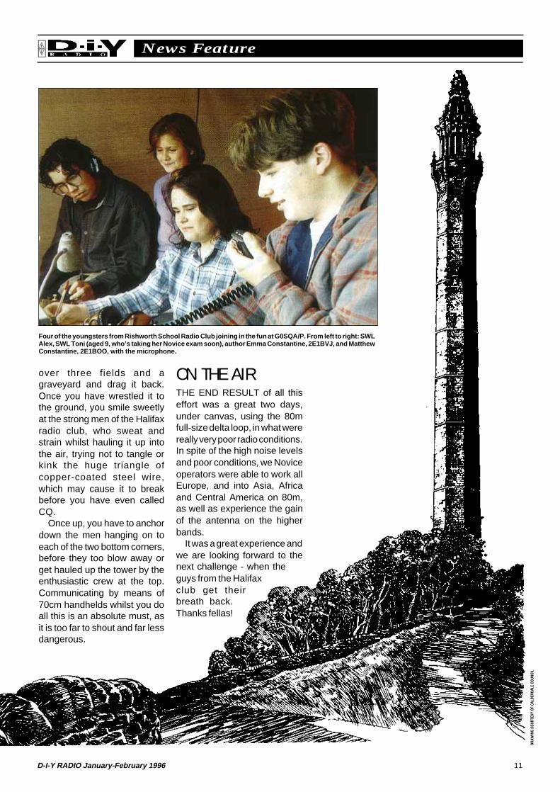
Four of the youngsters from Rishworth School Radio Club joining in the fun at G0SQA/P. From left to right: SWLAlex, SWL Toni (aged 9, who’s taking her Novice exam soon), author Emma Constantine, 2E1BVJ, and MatthewConstantine, 2E1BOO, with the microphone.
ON THE AIRTHE END RESULT of all thiseffort was a great two days,under canvas, using the 80mfull-size delta loop, in what werereally very poor radio conditions.In spite of the high noise levelsand poor conditions, we Noviceoperators were able to work allEurope, and into Asia, Africaand Central America on 80m,as well as experience the gainof the antenna on the higherbands.
It was a great experience andwe are looking forward to thenext challenge - when theguys from the Halifaxclub get theirbreath back.Thanks fellas!

Resistor
Resistor:variable
Potentiometer:presetadjustment
Resistor:presetadjustment
Potentiometer
Capacitor
Capacitor:variable
Capacitor:presetadjustment
Capacitor:electrolytic
Capacitor:feed-through
Capacitor:variabledifferential
Capacitor:variablesplit-stator
Inductorwindingor coil
Radio-frequencychoke
Inductor:iron-cored
Inductor:adjustableiron-core
Transformer:iron-cored
Inductor:tapped
Switches
Earth (chassis)
Earth (ground)
Antenna (aerial)
Bridgerectifier
Bridgerectifier
Coaxialsocket
Coaxialplug
Screenedwire
Transistors:bipolar
Collector
Emitter
C
E
B
Transistors:field-effect(FET)
Drain
D
Source
S
Gate
G
Base
Transistors:(MOSFET)
Transistors:(IGFET)
G
G2
G2
G1
G1
G
S
S
S
S
S
S
S
S
D
D
D
D
D
D
D
D
Single-gate
Single-gate
Dual-gate
Dual-gate
G
G
G2
G2
G1
G1
RSGBRSGB
Diode
Diode:light emitting
Diode:zener
Diode:variablecapacitance(varactor)
Diode:tunnel
Thyristor
Plug
Socket
Fuse
LampRelay
Solenoid
Contacts
Single cell
Battery
Meters
Jack socket
Open circuit
Closed circuit
Wiresjoined
Valve Valve
Indirectly heatedpetode
Directly heatedtriode
Wirescrossing
Temperaturesensor
Loudspeaker
Headphones
Morse key
Microphone
Crystal
RSGB, Lambda House, Cranborne Road, Potters Bar, Herts EN6 3JE
C RSGB DY253

Page intentionally left blankGo to next page

14 D-I-Y RADIO January-February 1996
Construction FeatureRSGB
An Audio Continuity TesterBy RobertSnary, G4OBE
THE IDEA OF test-ing for continuity isvery simple in that it
proves if there is a goodconnection between two pointsin a circuit. The tester in itssimplest form can consist of abattery and a bulb. Continuitycan also be tested using anohm meter. With this method oftesting you have to look at thebulb or the meter at the sametime that you are probing aroundin the circuit trying to checkcontinuity.
The most convenient way oftesting for continuity is to use amethod that gives an audioindication that continuity exists.You could use a buzzer and abattery but this can lead to thecurrent required for the buzzerbeing high enough to damagecomponents, particularly as thecurrent is intermittent with highcurrent ‘spikes’.
The tester described hereuses an integrated circuit to actas the oscillator which drives ahigh impedance (64 Ohm)Loudspeaker.
CIRCUITDESCRIPTIONTHE INTEGRATED CIRCUITIC1, see Fig 1 , is usually usedas an oscillator to flash an LED(Light Emitting Diode) from a1.5 Volt source, with a low powerconsumption. However, in thiscase, the IC is used to act as anaudio oscillator. Although theIC will provide enough drive fora low impedance speaker, the
use of a higher impedancespeaker ensures a low currentdrain. The oscillator frequencyis determined by the resistor R1and capacitors C1 and C2. It isalso affected by the supply ofvoltage as well as any resistancebetween the test probes.Although any AA size batterycan be used alkaline types arerecommended as they have alower internal resistance andare less likely to leak.
CIRCUITCONSTRUCTIONThe circuit could be built ‘DeadBug’ style with componentssoldered directly between thecomponent leads but forneatness it is better to follow theVeroboard layout shown in Fig2. The unit is built on a piece ofVeroboard measuring 7 stripsby 15 holes, and four track cutsneed to be made as shown inthe diagram (these areunderneath IC1). Once the trackcuts have been made then theFig 1: Continuity tester, circuit diagram.
C RSGB DY259

15D-I-Y RADIO January-February 1996
Construction FeatureRSGB
Veropins should be carefullysoldered in place, followed bythe wire link. Although no ICholder was used in the prototypeI would recommend that youuse one and this should next besoldered into place. Note thepolarity of the capacitor andcheck that it is place the rightway round.
After the components are allsoldered in, a quick visual checkof the board should be madebefore connecting the off boardleads and inserting IC1 into thesocket.
The two probes were madefrom a pair of meter leadspurchased at a rally. Analternative method is to makethe probes from thick (1.5 -2mm) copper wire fixed into anold Biro pen case with the centreremoved.
The circuit was originally
COMPONENTSResistorsR1 1kΩ 0.25 Watt 10% carbon resistor
CapacitorsC1 10µF ElectrolyticC2 0.1µF subminiature polyester capacitor. A
ceramic capacitor can also be used.SemiconductorsIC1 LM3909N
Additional Items 64Ω miniature loudspeaker, or pair of Walkman type
headphones (see text). If the headphones are used a3.5 mm stereo socket also is needed to allow connectionof the headphones to the rest of the circuit.
IC Holder Veropins Wire Two test leads. See text for details of how to make your
own. Battery holder for a single AA battery Veroboard 7 strips by 15 holes
Components are available from JAB ElectronicsComponents, 1180 Aldridge Road, Great Barr,Birmingham B44 8PB.
tested with a highimpedance loud-speaker from anold transistorradio found in myspares box.However highimpedance loud-speakers are attimes difficult tocome across soan alternative isto use a pair ofcheap ‘Walk-man’ type head-phones which
are usually 32Ω Impedance perear piece. These are thenconnected so that theloudspeaker connections aremade to the ‘Tip’ and ‘Ring’ ofthe stereo jack on theheadphones (Fig 3). This putseach ear piece in series and thetotal impedance is therefore64Ω. Use a stereo socket sothat the tip and ring can beconnected to the circuit.Alternatively, remove the jackplug from the headphones,connect the braiding of thescreened wires together andconnect the centre wires directlyto the circuit board.
TESTINGBEFORE POWERING UP thecircuit ensure the back of theVeroboard is clear of copperbits and that all the solderedjoints are good. Make sure thereare no solder bridges (soldershorting one track to another).
Make sure that the IC iscorrectly positioned and that allthe track cuts and the link are inthe correct place. Then thebattery can be inserted into theholder. When the probes areconnected together you shouldhear a tone from the loud-speaker or headphones.
BOXING THEPROJECTTHE CASE THAT WAS usedfor the prototype came from
one of my other hobbies,photography, and is in fact thebox some slides arrived in afterbeing processed. Any plasticbox is suitable and the boardand battery holder can be fixedusing double sided tape.
IN USETHE CONTINUITY TESTERwill give a different note betweena short circuit and low valueresistors and so will indicatecontinuity as well as possiblepoor soldered joints. The higherthe resistance the higher thepitch of the buzz in theheadphones or loudspeaker.
The tester will also indicate acoil or inductance by the soundof the note. It is worthwhileexperimenting with checkingdifferent value resistors beforeusing the circuit for serious faultfinding.
IMPORTANTSAFETY NOTICETHE CONTINUITY TESTERshould only be used onequipment which is switchedoff and disconnected from anypower source.
C RSGB DY260
Fig 2: Continuity tester, component layout.
Fig 3: Headphone connections.
C RSGB DY261

16 D-I-Y RADIO January-February 1996
On The AirRSGB
THE LOG BOOK
2’s CompanyNews and Reports from Novice Licensees
NEWS THIS time ofanother Novicelicensee who helps
to run a radio club. Mrs KathWilson, 2E1CNY, is themembership Secretary of theUK FM Group (Western) whichsponsors no less than 16repeaters covering the North-West of England, and North
Wales. If you use repeaters inthat area, drop Kath a line tofind out how to contribute totheir upkeep.
CONTESTSTHE NOVICE section of theUK Six Metre Group’sSummer Contest was won by
E P Williams, 2E1AFN/Pwho scored 129,150points from 88 contactson the 50MHz band.
Poole Radio Societyhas published the resultsof their first NationalNovice Contest. This tookplace last September onthe 50 and 432MHzbands. The 50MHzwinner was JamesMortimer, 2E1CXE, fromLeicester, whilst on 432the top place went to JoyFowler, 2E1DXA/M, inDerbyshire.
The two winnersreceived cups, as did
the sender of the neatesthand-written log, B Cannon,2E1DZQ, and all entrants weresent a certificate tocommemorate the event. A fullreport on the National NoviceContest appears in the January1996 edition of Ham RadioToday.
VHF CONVENTIONIF YOU HAVE ANY interest atall in building for, or operatingon, the VHF, UHF or microwavebands, you’ll find something foryou at the RSGB VHFConvention which is to be heldon Sunday 18 February.
The venue is SandownExhibition Centre, Esher,Surrey, and the packedprogramme includes a tradeshow, talks, RSGB committeesand trophy presentations.Further details can beobtained from Marcia at RSGBHQ (tel 01707 659015). Seeyou there.
The diagrams in D-i-Y Radio are drawn on a computer by Technical IllustratorBob Ryan, who is 2E1EKS.
33 countries on 50MHz. A new country for
almost everybody was the appearance of
3V8BB, a club station in Tunisia , on 50MHz
during October.
3V8BB was also much in evidence during
the CQ World Wide DX contests, both in the
SSB event in October and the CW leg a
month later. Even if you do not compete in
these major HF contests, they still provide
an excellent opportunity to hear or work
new DX countries. Propagation conditions
were particularly good during the SSB event,
with over 100 countries being worked from
the UK on each of 10, 15, 20, 40 and 80
metres. What was unexpected was the
good propagation on the 28MHz band, with
a number of VK (Australia ) and ZL (New
EVEN THOUGH we are probably
several years away from the return of
spectacular world-wide openings on
50MHz, it is still worth checking that
band from time to time. Even under
absolutely ‘flat’ conditions, distances of
several hundred kilometres can be
worked even with low power and simple
antennas. By way of an example,
2E1CSD in Grantham, Lincolnshire,
worked GD4XTT on the Isle of Man
using 3W on 22 October, Sweden.
During 1995, 2E1AIU in Essex worked
28 countries, and 2M0AEU (now
GM0WDD) in Edinburgh worked over
Marios Nicolaou, 5B4WN, is a Cypriot medicalstudent at Nottingham university. Here he isoperating during the CQ World Wide SSBcontest.

17D-I-Y RADIO January-February 1996
On The AirRSGB
THE LOG BOOK
The Amateur Radio Spectrum: The 12 metre Band
Band by BandTWELVE metres,the 24MHz band, isone of the three so-
called ‘WARC Bands’. It wasallocated to amateurs during theWorld Administrative RadioConference (WARC) in 1979along with 30 and 17m. It is onlyavailable to amateurs with thefull Class A licence.
It is a particularly useful bandto those running low power(QRP) or using simple antennas,such as the dipole shown in Fig1. This is because relativelyfewer stations use the band(compared with, say, 20 or 15metres) and therefore there isgenerally less interference,allowing weaker signals to bemore easily heard.
Propagation is similar to thatexperienced on the 15 metreband (see D-i-Y Radio,September - October 1995)although, being higher infrequency, it is less reliable than15m during sunspot minimumyears. But good DX (longdistance) signals can still beheard, particularly on north -
which in this case is only about6m or 20ft.
When rare DX stations showup on 12m, there can be plentyof competition to work them.However, no contests are per-mitted on this band, so 12m isoften used by amateurs wantingmore ‘leisurely’ contacts.
south paths, such as from SouthAfrica or South America.
It may prove difficult to find acheap receiver kit which coversthe 12m band, so an old second-hand receiver or transceivermay be the answer for those ona tight budget. Do check,though, that older equipmentcovers the band: all moderncommercial HF transceiverscover 12m, but equipment fromthe 1970s may not!
A simple half-wave dipole(see Fig 1) will generally workquite well on 12m, because itcan easily be erected at a half-wavelength above ground,
BAND FACTSAllocation: 24.890 - 24.990MHz (Full A licence only)Activity: 24.890 - 24.920MHz CW, 24.920 - 24.929MHzDigital modes and CW, 24.931 - 24.990MHz SSB phone.Notes: 24.929 - 24.931MHz should be kept clear forinternational propagation beacons.
Fig 1: a simple half-wave dipole for the 12m (24MHz) band. If possible, it should be erected at least 20ft high, andas far away from other objects as possible.
C RSGB DY263
Zealand ) stations in people’s logs, whichis very unusual at this stage in the sunspotcycle. Another very rare DX countryworked on 28MHz, as well as otherbands, was Myanmar (formerly Burma),from where both XY1HT and XZ1A wereactive.
Other interesting stations loggedduring the CQ World Wide SSB contestincluded ZC4DX (British SovereignBases on Cyprus ) - this was a Britishexpedition specifically for the contest,KH0AM (Northern Mariana Islands inthe Pacific), 6D2X (a special prefix forMexico ), KC6MW (Republic of Belau ),VQ9IO (Chagos Archipelago ), and
numerous stations in the Caribbean area,
including VP2E (Anguilla ), VP2VF (British
Virgin Islands ), VP5WW (Turks and
Caicos Islands ) and V26B (Antigua ).
QSL card from LY3DF, who was worked duringthe CQ World Wide SSB contest.
There are a number of contests during
January and February, most of which
concentrate on the lower-frequency
bands - 40, 80 and 160 metres. The CQ
World Wide 160m Contests are on 26 -
28 January (CW) and 23 - 25 February
(SSB). Both events start at 2200UTC
on the Friday and end at 1600UTC on
the Sunday. There are also several
RSGB contests: the Affiliated Societies
(or ‘AFS’) Team Contests on 14 January
(CW) and 20 January (SSB), the 1.8MHz
CW Contest on 10 / 11 February, and
the 7MHz CW DX Contest on 24 / 25
February.

18 D-I-Y RADIO January-February 1996
News FeatureRSGB
Joining the ‘Band’ Wagonby Peter Wood,G0HWQ
ARE YOU HANGINGaround on the edgeof this glorious hobby
of amateur radio wonderingwhether or not it’s for you? TonyHancock who did that skit on TVall those years ago has a lot toanswer for. But the slightlyeccentric image of the hobby isno more and you don’t need tobe a mad scientist to build someof your own gear either!
So could you do it? From myexperience the answer has tobe a resounding ‘YES’. The mostimportant incentive for me wasto get listening cheaply on theshort-wave bands. I hadsoldered the odd wire but nevertackled such a project before. Ihave since made up severalprojects from kits and would liketo tell you about a couple thatmight set you on the road toconstruction and perhaps toobtaining an amateur licenceyourself.
I CAN DO THATMY INTEREST in amateur radiowas kindled dramatically backin 1985 when my family and Iwere staying with friends in theMidlands for a short period. One,an old school friend was now a‘licensed amateur’ and heoffered to give us a demon-
stration. The experience had anamazing effect on me. I hadlistened to broadcast radios allmy life but had never thoughtseriously of being able to talkback to the people I was hearing!It was a case of “I could do that”,but I had no idea of what wasinvolved. I was impressed bythe possibility of being able totalk with my old school pal frommy home in South East England.
THE BUGWHAT I HAVE just described iscommonly known as ‘catchingthe bug’. The effect was anoverwhelming urge to obtain ashort-wave receiver so I couldlisten to radio amateurs doingwhat I hoped to do myselfeventually - talking to othersaround the world.
I joined a radio club where Itried to get some idea of what itwas I needed. Members quizzedme on my long-term intentions.Why wasn’t I studying for theRadio Amateur’s Exam (RAE)?Which bands was I interestedin? How did I know? What bandswere there? A scan of the manyradio magazines I had boughtdidn’t shed much light on thesubject either. Most of thesecond-hand short-wavereceivers for sale were identifiedby model numbers which meant
nothing to me. The pricesseemed ridiculously high forwhat might, for me, just be apassing phase and the localelectronics shop didn’t have alot of suitable second-hand gearin stock.
What to do? During my avidreading of the radio magazines,I’d spotted some short-wavereceiver kits and wondered if Imight be able to put onetogether. In the end I took thebull by the horns and bought akit. Since that time I have goneon to sit the RAE and take theMorse Test, and have held alicence now for several years.The first receiver I built myselfholds a special place in myaffections. It has been lent toothers showing a gleam ofinterest in the hobby. I have nopretensions to special technicalknowledge or a background inelectronics, so read on.
BUILD A KITC M HOWES Communicationsat Daventry, Northants andKanga Products of Folkestone,Kent both produce a range ofkits which include what arecalled short-wave directconversion receivers. Both ofthose I built (one from eachcompany) run from arecommended 12 to 14V DC
AdvertisementAdvertisement

19D-I-Y RADIO January-February 1996
News FeatureRSGB
supply. They will, however, runfrom a 9V battery.
The one I put together at thebeginning of my amateur radiocareer was the 80m version fromC M Howes. More recently byway of a comparison I built the‘Sudden’ 40m direct conversionreceiver designed by GeorgeDobbs, G3RJV, who is the vicarof Sudden in Rochdale.
The 80m kit was the firstproject I had tackled but this didnot matter a bit. The instructionsare exceptionally clear andinclude tips on soldering. Anypotentially tricky bits areanticipated so that you areforewarned, making them quiteeasy. No special tools areneeded, either, apart from asmall-tipped soldering iron,some small side-cutters forstripping wire, a small trimmingtool for adjusting the core of thecoil during the simple‘alignment’, or setting up, stage
at the end and a pair of long-nosed pliers. (A set of tweezerswill do for the latter if we aretalking basics!)
PARTS SUPPLIEDBOTH PRODUCTS come witha full list of parts together withdetails of how to identify them,circuit diagrams and otheruseful information, including (inthe case of the Howes kit),details about erecting a simpledipole aerial.
All the parts needed aresupplied but you are advised tocheck them before you start. Inthe case of the Howes kit, theprinted circuit board (or PCB)on which the parts are to befitted, is marked with the shapeof the components so it’s verydifficult to get it wrong. Theessence of a successful projectis to check you’ve got the rightcomponent wired into the right
holes before you solder, andcheck your work at the end ofeach stage as you progress.
Soldering the components onthe PCB of either kit can takeless than an hour but why hurry?Both receivers worked first time,once I had discovered that I hadwired up the socket for theloudspeaker on the Howesreceiver back to front - an easymistake to make as you nearthe exciting point of finding out ifit’s going to work or not.
It is hard to imagine thepleasure in putting together aproject that actually works. Ibegan with my first receiver tolearn about amateur radio in aserious way. This proved to bevery helpful basic work when Icame to study for the RAE.
Several years later, I alsoenjoyed putting together the‘Sudden’, which really did workfirst time. It, too, is out on loannow, encouraging someoneelse to join the ranks.
Advertisement

20 D-I-Y RADIO January-February 1996
Construction FeatureRSGB
Experimental 430MHz AntennaMake thiseasy-to-buildhigh-gainantenna for the70cm band.
MOST OF THEantennas that youwill know are ofthe type known as
resonant antennas. Antennasare broadly classified as eitherstanding wave (resonant) ortravelling wave (non-resonant). Standing waveantennas, such as a dipole, arenarrowband (operate over anarrow range of frequencies),whilst travelling wave systemsare broadband (able to workover a wide range of frequen-cies).
The rhombic is an exampleof a travelling wave (non-resonant) antenna. It is usuallyused for fixed commercial andmilitary short-wave radio links.It is constructed with wire, in adiamond configuration, sup-ported by four masts. It is veryeffective with lots of gain (theability of an antenna to transmitor receive more effectively inone direction at the expense ofother directions - see Fig 1 )and its dimensions are not at all
Fig 1: The horizontal polar diagrams of the small rhombic antenna and a dipole compared.
C RSGB DY262
pared in Fig 1 (The dipole hasthe figure of eight pattern).
Unlike the Yagi this antennahas no critical dimensions, soyou don’t have to worry if thesize is not within a couple ofcms. Additionally it can be foldedup to be transported in a car - oreven on a bicycle!
A rhombic has a fairly highfeed impedance and is usuallyfed with balanced twin feeder. Ifwe are to use 50Ω coaxial cableto feed it we need a matchingtransformer. A half wave coaxialbalun (balance to un balancedtransformer), constructed froma halfwave length of coaxialcable, can be used. This deviceis a four-to-one stepdowntransformer, which matches thebalanced antenna to the un-balanced coax feeder.
ANTENNACONSTRUCTIONTHE ANTENNA FRAME ismade of 1cm x 2cm wood stripsfixed to a plywood centre, using30mm long M4 bolts, as shownin Fig 2a . The outer bolts fixingthe front and side wire supportscan be removed so that theantenna can be folded up fortransportation, as shown in Fig2b .
The wires are fixed to thefront and rear wire supportsusing screw connectors, see Fig2a, details X and Y. The wire isfed through holes in the sidewire supports.
The antenna is fixed to a mastusing a small shelf bracket. Oneend of the bracket is fixed to theplywood centre using the samebolts that hold the wood rearwire support. The other end ofthe bracket can be fixed to themast using either screws or ahose clamp (jubilee clip).
critical. However, it has notfound its way into amateurradio use because of the amountof space it takes up. Forexample, an effective rhombicneeds each side of the diamondshape to be at least twowavelengths long. A rhombicantenna for the 20 metre bandwould have to be supported onpoles some 40 metres apart.Another dis-advantage is that,with such a structure, it cannotbe rotated!
The rhombic will work over awide range of frequencies. AtHF it is possible to design arhombic that will work on the 7,10, 14, 18, 21 and 28MHzbands. A rhombic for the lowerVHF frequencies could be madeto work on the 50, 70 and144MHz bands.
Its main disadvantage (largesize) is less of a problem atUHF. You can make a portablerhombic for the 70cm band sothat you can have fun workingDX from high ground, even withyour handheld transceiver.
The antennadescribed in thisarticle has a gainof up to 9dB overa dipole. Con-necting yourtransmitter to anantenna with9dB gain is theequivalent ofincreasing thepower of yourtransmitter eighttimes - and itincreases re-ceived signalsby the sameamount. Thehorizontal polardiagrams of thesmall rhombicantenna and adipole are com-

21D-I-Y RADIO January-February 1996
Construction FeatureRSGB
BALUNTRANSFORMERCONSTRUCTIONTHE MOST DIFFICULT part ofthe construction is making thecoaxial balun. Cut a 27cm lengthof cable.
Cut back the outer insulation2cm each end. Make a ‘pigtail’at each end of the braid outer.Cut back the centre insulatormaterial 1cm each side so thatthere is 1cm of centre conductorexposed. Detail Y of Fig 2 showswhat is needed.
C RSGB DY255
Prepare the coaxial cablewhich goes to the transceiverin the same way as describedabove. Solder the braidingtogether allowing soldering ironto melt the solder until it flowsthrough the braid. Do not leavethe soldering iron on the braidtoo long or the centre insulatingmaterial of the cable will bedamaged.
Connect the cables togetheras shown in detail Y of Fig 2a.Tape the coaxial cable to therear wood support and connectthe other end to your radio.
Fig 2: Construction of the UHF rhombic antenna.
USING THEANTENNAASSEMBLE THE ANTENNAas shown in Fig 2 and fit itto a pole. It can be usedhorizontally (most SSB stationsuse horizontal polarisation) orvertically (for FM). Connect yourtransceiver to the antenna andtune for any repeaters in thevicinity. If your transceiver hasan S-meter there should belarge changes in S level asthe antenna is rotated.

22 D-I-Y RADIO January-February 1996
RSGB Letters and Diary
Keep sending your letters and photographs to:The Editor, D-i-Y Radio, RSGB, Lambda House, Cranborne Road, Potters Bar,Herts, EN6 3JE, and we will send a pen to the sender of each letter published.
REMEMBERINGCOLOURSI HAVE JOTTED down my way ofremembering the ‘new’ mains plugcolours:
Line = frizzles you to a crisp -Brown.
Neutral = blue-eyed boy, neutraland safe - Blue.
Earth = grows buttercups anddaisies, harmless andlovely - Yellow / Green.
I wonder if you will publish this asan alternative way for theyoungsters to remember. I’msurprised the Novice RadioAmateurs’ Exam results on thiswere so poor, but even when youget a plug wired on to an electricaldevice in a shop the assistants getit wrong, as Which magazine foundout.
Colin Sumner, G0POS
JANUARY14 Affiliated Societies Team Contest (CW). 1400 - 1800UTC, 3.510 - 3.590MHz.16 LF Cumulative Contest (1.8MHz CW). 2000 - 2200UTC, 1.830 - 1.870 & 1.950
- 1.960MHz.20 Affiliated Societies Team Contest (SSB). 1400 - 1800UTC, 3.600 - 3750MHz.20 RSGB HQ Saturday Opening. 10am - 4pm, Visit the Book Shop, the GB3RS
Shack and the National Amateur Radio Museum & Library. Morse tests available*.21 Oldham Amateur Radio Club Mobile Rally, Queen Elizabeth Hall, Civic Centre,
West Street, Oldham, Lancs. Details 01706 846143 or 0161 652 4164.21 LF Cumulative Contest (3.5MHz CW). 1600 - 1800UTC, 3.530 - 3.580MHz.24 LF Cumulative Contest (1.8MHz CW). 2000 - 2200UTC, 1.830 - 1.870 & 1.950
- 1.960MHz.27 LF Cumulative Contest (3.5MHz CW). 1600 - 1800UTC, 3.530 - 3.580MHz.
FEBRUARY1 LF Cumulative Contest (1.8MHz CW). 2000 - 2200UTC, 1.830 - 1.870 & 1.950
- 1.960MHz.2 Lancastrian Rally, University of Lancaster, Just off jcn 33 M6. Details 01524
64239 or 0374 290088.2 South Essex Amateur Radio Society Rally, The Paddocks, Long Road, Canvey
Island, Essex. Details 01268 697978.4 432MHz Fixed/AFS Contest. 0900 - 1500UTC.4 LF Cumulative Contest (3.5MHz CW). 1600 - 1800UTC, 3.530 - 3.580MHz.11 Cambridge and District Amateur Radio Club, Ambulance Station, Addenbrookes
Hospital. Details 01954 200072.11 Northern Cross Rally, Thornes Park Athletics Stadium, Wakefield. Details 0113
238 3622.17 RSGB HQ Saturday Opening. 10am - 4pm, Visit the Book Shop, the GB3RS
Shack and the National Amateur Radio Museum & Library. Morse tests available*.18 RSGB VHF Convention, Sandown Exhibition Centre, Esher, Surrey. Trade
Show, Lectures, Committees, RSGB Book Stand. Details 01707 659015.24 11th Rainham Radio Rally, Rainham School for Girls, Derwent Way, Rainham,
Gillingham, Kent ME8 0BX. RSGB books available. Details 01634 365980.24 Tyneside Amateur Radio Society Rally, Temple Park Centre, South Shields.
RSGB books available. Details 0191 265 1718.24 /257MHz DX CW Contest. 1500 - 0900UTC, 7.000 - 7.030MHz.25 Barry Mobile Rally, Barry Leisure Centre, off Holton Road, Barry. Details 01222
832253.* Candidates for Morse Tests must bring with them two passport-style photographs and thenecessary fee. Tests are available on RSGB HQ Saturday Opening days from 11am to 12.30pm.
Advertisement

Advertisement

Advertisement