#114 awa news aug 2015 - awasa home · pdf filevisit our website: being away on leave these...
TRANSCRIPT

Visit our Website: www.awasa.org.za
Being away on leave these
last few weeks really makes
me appreciate more and
more the worth of my shack
and fixed antenna.
I have been battling with a
mobile setup, compromised
antenna and RF getting in
to my transmissions, some-
thing which I have never
had a problem with in my
permanent shack setup.
Having to try and sort out
problems while away from
home without any kind of
test equipment is to say the
least, a challenge which I
am not up to, but yet with
the help and assistance of a
few friends, most of the
problems have been sorted
out.
This also makes me realise
the value of having people
who are able to give valua-
ble input to not only sort
out problems, but to assist
in making sure that the
signal that goes out the
spout, is as clean as possi-
ble.
Maybe we don’t like to hear
when our audio is rough or
the signal is not up scratch,
or we cant be heard proper-
ly because of the way we
have setup our antenna,
but I realised that this is
just another phase of being
a radio amateur.
Nothing we do is cast in
stone. Things can change at
the drop of a hat. A fuse
can blow, an antenna can
short, a microphone can go
faulty. If we did not rely on
reports from those we are
in contact with, then we
spend our time with our
heads stuck in the ground,
thinking that all was fine,
and nobody would be able
to understand a word we’re
saying.
Most times, I would say
that people have good in-
tentions in letting you know
when you have a problem.
More often than not it is not
meant to be malicious, alt-
hough sometimes we don’t
think so.
I know that it is hard to ac-
cept criticism from people,
especially when you think
you have a grand station
setup and believe nothing
could go wrong. But all it
takes is a little bit of humble
pie to accept the advice of
others, or the reports of oth-
ers and sort out whatever it
is that ails your transmis-
sion, to have a perfectly
readable signal.
Just ask me, I know exactly
what it feels like to be put
through it all. But believe me
too when I say, it was well
worth it.
Best 73
DE Andy ZS6ADY
AWA Committee:
∗ President—Ted
ZS6TED
∗ Vice Pesident—
Jacques ZS6JPS
∗ Technical Advisor—
Rad ZS6RAD
∗ Secretary/PRO—
Andy ZS6ADY
* Western Cape—John
ZS1WJ
* KZN—Don ZS5DR
* Historian—Richard
ZS6TF
HF Happenings 2
HF & VHF
Aerials on the
Comet Airliner
3-5
AWA Grading
Standard
6-7
Notices 8
Inside this issue:
Reflections:
Newsletter
Aug 2015 # 114
A Mem-ber of the
SARL
WIKIPEDIA
Wireless Telegraphy Wireless telegraphy dates as far back as Faraday in the early 19th century, when it was discovered that radio waves could be used to send telegraph messages.
In the mid-1860s, James Clerk Maxwell predicted the existence of electromagnetic waves and showed that their propaga-tion speed is identical to that of light. After that, in reality, it required very little to demonstrate by experiment the exist-ence of such waves.
Calzecchi-Onesti
By 1884, Temistocle Calzecchi-Onesti in Fermo, Italy, developed a primitive device that responded to radio waves. It consisted of a tube filled with iron filings, called a "coherer". This kind of device would later be developed to become the first practical radio detector. Writing in the Rendiconti of the Lombardy Institution regarding the discovery of the coherer, directs attention to his experiments made in 1884, before Branly had worked on the subject. He further points out the part played by Augusto Righi in wireless telegraphy.
Calzecchi found that the conductivity of metal powder varied depending on the incidence of radio waves. However, Calzecchi's experiments were not widely reported. He would later write Le mie esperienze e quelle di Edoardo Branly: Sulla conduttività elettrica delle limature metalliche (tr., "My experiences and those of Edward Branly: The electrical conductivity of metal filings
Page 2 Newsletter
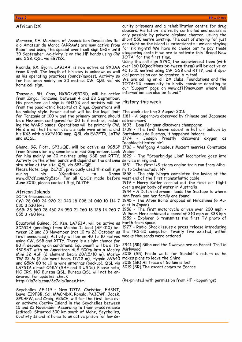
African DX Morocco, 5E. Members of Association Royale des Ra-dio Amateur du Maroc (ARRAM) are now active from Rabat and using the special event call sign 5E2E until 30 September. Ac-tivity is on the HF bands using CW and SSB. QSL via EB7DX. Rwanda, 9X. Bjorn, LA9IAA, is now active as 9X0AA from Kigali. The length of his stay is unknown as well as his operating practices (bands/modes). Activity so far has been mainly on 20 metres CW. QSL via his home call sign. Tanzania, 5H. Chas, NK8O/VE3ISD, will be active from Zinga, Tanzania, between 4 and 28 September. His promised call sign is 5H3DX and activity will be from the paedi-atric hospital at Zinga. Operations will be holiday style. Power output will be the legal limit for Tanzania at 100 w and the primary antenna should be a Hexbeam configured for 20 to 6 metres, includ-ing the WARC bands. Operations will be primarily CW. He states that he will use a simple wire antenna and his KX3 with a KXPA100 amp. QSL via EA7FTR, LoTW and eQSL. Ghana, 9G. Piotr, SP3UQE, will be active as 9G5SP from Ghana starting sometime in mid-September. Look for him mainly on 20 me-tres using SSB and RTTY. Activity on the other bands will depend on the antenna situ-ation at the site. QSL via SP3UQE. Please Note: Sigi, DL7DF, previously used this call sign during his DXpedition to Ghana www.dl7df.com/9g5sp/. For all QSOs made before June 2015, please contact Sigi, DL7DF. African Islands IOTA frequencies CW: 28 040 24 920 21 040 18 098 14 040 10 114 7 030 3 530 kHz SSB: 28 560 28 460 24 950 21 260 18 128 14 260 7 055 3 760 kHz Equatorial Guinea, 3C. Ken, LA7GIA, will be active as 3C7GIA (pending) from Malabo Is-land (AF-010) be-tween 12 and 23 November (not 10 to 22 October as first announced). Activity will be on 40 to 10 metres using CW, SSB and RTTY. There is a slight chance for 80 m depending on conditions. Equipment will be a TS-480SAT with an Ameritron ALS 500m into a Mosley Mini 32 ASP (2 element beam 20/15/10 m), Mosley TW 22 M (2 ele-ment beam 17/12 m), Hygain AV640 and G5RV 80 to 10 m wire antennas (backup). QSL via LA7GIA direct ONLY (SAE and 3 USDs). Please note, NO IRC, NO Bureau QSL. Bureau QSL will not be an-swered. For updates, check http://la7gia.com/3c7gia/index.html Seychelles AF-119 – New IOTA. Christian, EA3NT, Dave, EI9FBB, Col, MM0NDX, Ronald, PA3EWP, Jacek, SP5APW, and Craig, VK5CE, will for the first time ev-er activate Coetivy Island in the Seychelles between 15 and 23 November. According to their press release [edited]: Situated 300 km south of Mahe, Seychelles, Coetivty Island is home to an active prison for low se-
curity prisoners and a rehabilitation centre for drug abusers. Visitation is strictly controlled and access is only possible by private airplane charter, us-ing the short 550 metre airstrip. The cost of staying for just one night on the island is extortionate – we are staying for six nights! We have no choice but to pay these staggering costs if we are to activate this 'Brand New IOTA' for the first time. Using the call sign S79C, the experienced team (with over 160 DXpeditions be-tween them) will be active on 40 to 10 metres using CW, SSB and RTTY, and if spe-cial permission can be granted, 6 m too! We are calling on all DX clubs, Foundations and the IOTA/DX community to kindly consider donating to our ‘Support’ page on www.af119new.com where full information can also be found." History this week The week starting 3 August 2015 1181 – A Supernova observed by Chinese and Japanese astronomers 1693 – Dom Pérignon discovers champagne 1709 – The first known ascent in hot air balloon by Bartolomeu de Gusmao, it happened indoors 1774 – Joseph Priestly discovers oxygen as "dephlogisticated air” 1782 – Wolfgang Amadeus Mozart marries Constanze Weber 1829 – The "Stourbridge Lion" locomotive goes into service in England. 1831 – The first US steam engine train run from Alba-ny to Schenectady, NY 1858 – The ship Niagra completed the laying of the west end of the first transatlantic cable 1919 – Harry Butler carried out the first air flight over a major body of water in Australia 1944 – A Dutch informant leads the Gestapo to where Ann Frank and her family are found 1945 – The Atom Bomb dropped on Hiroshima (6 Au-gust in Japan) 1956 – The first motorcycle driven over 200 mph - Wilhelm Herz achieved a speed of 210 mph or 338 kph 1959 - Explorer 6 transmits the first TV photo of Earth from space 1977 - Radio Shack issues a press release introducing the TRS-80 computer. Twenty five existed, within weeks thousands were ordered 2941 (SR) Bilbo and the Dwarves are on Forest Trail in Mirkwood 3018 (SR) Frodo waits for Gandalf's return as he makes plans to leave the Shire 3018 (SR) All trace of Gollum is lost 3019 (SR) The escort comes to Edoras (Re-printed with permission from HF Happenings)
HF & VHF AERIALS ON THE COMET AIRLINER, by Richard ZS6TF AWA historian
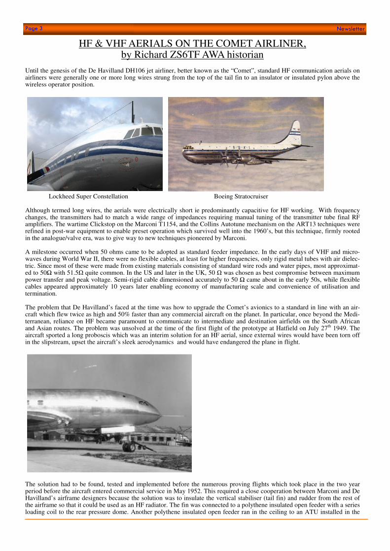
Until the genesis of the De Havilland DH106 jet airliner, better known as the “Comet”, standard HF communication aerials on airliners were generally one or more long wires strung from the top of the tail fin to an insulator or insulated pylon above the wireless operator position.
Lockheed Super Constellation Boeing Stratocruiser Although termed long wires, the aerials were electrically short ie predominantly capacitive for HF working. With frequency changes, the transmitters had to match a wide range of impedances requiring manual tuning of the transmitter tube final RF amplifiers. The wartime Clickstop on the Marconi T1154, and the Collins Autotune mechanism on the ART13 techniques were refined in post-war equipment to enable preset operation which survived well into the 1960’s, but this technique, firmly rooted in the analogue/valve era, was to give way to new techniques pioneered by Marconi. A milestone occurred when 50 ohms came to be adopted as standard feeder impedance. In the early days of VHF and micro-waves during World War II, there were no flexible cables, at least for higher frequencies, only rigid metal tubes with air dielec-tric. Since most of these were made from existing materials consisting of standard wire rods and water pipes, most approximat-ed to 50Ω with 51.5Ω quite common. In the US and later in the UK, 50 Ω was chosen as best compromise between maximum power transfer and peak voltage. Semi-rigid cable dimensioned accurately to 50 Ω came about in the early 50s, while flexible cables appeared approximately 10 years later enabling economy of manufacturing scale and convenience of utilisation and termination. The problem that De Havilland’s faced at the time was how to upgrade the Comet’s avionics to a standard in line with an air-craft which flew twice as high and 50% faster than any commercial aircraft on the planet. In particular, once beyond the Medi-terranean, reliance on HF became paramount to communicate to intermediate and destination airfields on the South African and Asian routes. The problem was unsolved at the time of the first flight of the prototype at Hatfield on July 27th 1949. The aircraft sported a long proboscis which was an interim solution for an HF aerial, since external wires would have been torn off in the slipstream, upset the aircraft’s sleek aerodynamics and would have endangered the plane in flight.
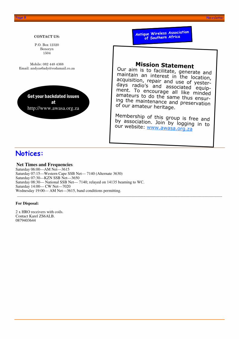
The solution had to be found, tested and implemented before the numerous proving flights which took place in the two year period before the aircraft entered commercial service in May 1952. This required a close cooperation between Marconi and De Havilland’s airframe designers because the solution was to insulate the vertical stabiliser (tail fin) and rudder from the rest of the airframe so that it could be used as an HF radiator. The fin was connected to a polythene insulated open feeder with a series loading coil to the rear pressure dome. Another polythene insulated open feeder ran in the ceiling to an ATU installed in the
Page 3 Newsletter

Page 4 Newsletter
radio crate which accommodated all the HF, VHF communications and navigation equipment. The VSWR of this system at a feeder impedance of 50 ohms was 1.5 to 1 or better over a range of 2 to 18 MHz. A remotely controlled earthing switch was installed across the 4000 volt tail fin insulating barrier to be used during electric storm conditions.
View of the Radio “Crate” in the sole surviving complete Comet 1 airframe at Coxford
The fully equipped crate illustrated in a Marconi advertisement in Flight Magazine. (The lower rack l to r contains the intercom station, DF switch box, Dual communication receivers ,bearing indicator, loop controller and master receiver controller. Above are HF amplifier and drive units, ADF receiver units, power supplies, intercom power supply, glide path localiser and marker).
VHF communications presented different problems. A fan aerial encased in a dielectric cover was situated in the highest point on the aircraft in the tail fin tip. It resembled a delta loop but was actually a monopole loaded against the fin as VHF RF earth. Static build up was bled to earth by resistors connected across the co-axial socket at the base of the aerial. The problem of high voltage HF potentials finding
a path back into the VHF feeders was ingeniously solved with a filter composed of 3 λ/4 stubs at the aft end of the coaxial feeder from the radio. The input to the filter was a 50Ω coaxial line from the crate. The output from the filter was a twin twisted pair which connected below the fin insulator strip to a 1.75λ coax feeder line, the outer earthed at the antenna socket and again to the fin at ¼ λ below it. This elaborate composite feeder design kept the SWR to 1.5 or below over the range 118 to 132 MHz, while preventing unwanted VHF radiation from the fin itself.
The ADF (Automatic direction finding) loop and sense aerials were let into hatches on top of the fuselage with another separate sense aerial, an insulated metal strip mounted on the centre section rear access door. These were connected to a dual sense amplifier which connected to two ADF receivers. NDB’s (Non directional beacons) located at airfields en-route, broadcast between 200-415 kHz using a CW identifier. The sense aerial enabled discrimination against a re-ciprocal heading. Reliable range in those days was about 200 miles.
The ADF indicator consisted of a needle and a compass card on the equipment, repeated in the cockpit. The aerials for the localiser (lateral) component of the ILS ( instrument landing system) and the VOR (VHF Omni Directional Radio Range) were identical folded unipoles covering 108 to 118 MHz, profiled to be installed in the port and starboard tail-plane tips respectively. The 75MHz ILS marker aerial was a rod aerial in a cavity mounted behind a dielectric window in the aircraft skin in the underside of the port inner engine nacelle. The 333 MHz ILS glide path aerial was a horizontal dipole with

Page 5 Newsletter
reflector mounted behind the cockpit window. The DME aerials (distance measuring equipment developed from the wartime IFF/BABS system still termed “Rebecca” in those days), comprised two forward looking horizontal slots, with cavities behind, fitted either side of the nose for reception. The slots had fibreglass covers and the coupling into the cavities was a folded unipole for broad band operation. The transmitting antenna was a single slot mounted dead centre in the nose floor, constructed similarly to the receive slots. The original system operated in the 200 MHz band.
The Marconi AD94 HF communication receiver, a 12 valve superhet with a 30 foot direct reading film scale covering 150 to 510kHz and 2 to 18.5MHz
Considering that the Comet first flew 5 years after WW2 and went into commercial service 3 years later, the development of airborne and ground communication and navigation equipment to cope with the extra perfor-mance yet short range of the aircraft, was equally intense and revolutionary as the aircraft itself. This set the scene for jet airliner operations until the present day. The innovative RF engineers at the Marconi Wireless Tele-graph Company based in Chelmsford UK designed all the equipment in close collaboration with the aircraft designers, establishing themselves as leaders in the field at the time. Footnote: Your historian’s original article on the Comet written in 2012 on the 60th anniversary has been posted to the AWA website.
Erratum: last months article gave 1953 as the release of the 6146 and named the WW2 rearward looking radar as “Rebecca”.
The release date of the 6146 was May 1 1952 and the radar name should have been “Monica”. Thanks to John ZS5JF and Peter
ZS6FS for these corrections.

Page 6 Newsletter
The Following method of grading the worth of our radio’s has been drawn up assessed by the Committee of the AWA and alt-hough a recommended way of identifying certain qualities and values of the rigs we love, it is not a be all and end all to grading. This Grading Standard should be used in conjunction with the Assessment Form which is available on the AWA website under “Technical Downloads”.
Mint Condition 90-100 Mint condition is defined as the same condition in which the set left the factory when it was man-ufactured. A set in mint condition will be functioning perfectly, there will be no damaged or miss-ing parts, no signs of wear and tear, and the cabinet finish will be perfect without a single sign of use. The phrase "mint condition" is a very over used one when describing the condition of radio equipment. There are very few radios which actually qualify as "mint". From a base of 90 the following items would increase the points Original microphone Original operators manual Original Service and overhaul manual Factory service bulletins and upgrades professionally installed Spare set of new original type valves OEM accessories, cases, covers, external VFO’s if also mint. Original packing Original invoice Full ownership history Excellent Condition 80-89 A complete set in excellent condition is completely functional to manufacturer’s specification. It will have no missing or damaged parts, show only minute (nearly undetectable) signs of wear and tear, and the cabinet and front panel will be nearly perfect, without scratches or dents and there is minimal dust on the chassis The radio may have aged and had components replaced with professional workmanship but no modifications unapproved by manufacturer From a base of 80 the same items as for Mint would increase the points . Very Good Condition 70-79 A complete set in very good condition will be completely functional to manufacturers specifica-tion. There will be signs of wear and tear and the front panel and cabinet may be minimally scratched. Damaged or missing parts may have been replaced. The cabinet may have been re-painted. From a base of 70 with all of these defects apparent, the fewer defects will result in a higher score. Good Condition 60-69 Good radios are fully functional or easily repairable. A few minor missing easily obtainable parts, normal wear and tear, extra non-defacing holes, panel scratches, minimal corrosion acceptable but The radio may have had components replaced with good workmanship but will have no fac-tory unapproved modifications Incomplete radios will be rated from 60 to 65 dependant on type and number of omissions. Com-plete radios with minor faults between 66 and 68 and fully functional radios with minor but appar-ent defects 69. Note radios with extra holes in the front panel are graded fair.
AWA GRADING STANDARDS FOR COLLECTIBLE RADIOS
DISCLAIMER : This grading system is made available to assist AWA members in self-assessment of the condition of collectable radios and associated equipment in their posses-
sion. Its use for any other purpose whatsoever is at the user’s sole risk.

Page 7 Newsletter
Fair Condition 40-59 Usually not be completely functional, but it will be repairable with significant labour. There may be a few missing parts which may be difficult to obtain. There will be signs of excessive wear and tear and lots of chassis grime due to prolonged use. The cabinet and front panel will probably re-quire refinishing and the chassis may have age related corrosion as a matter of routine. Non-factory modifications may have been installed in the radio. Corroded and defaced rigs will be in the lower scores below 50, the level of completeness and difficulty and cost of sourcing spares will affect the rating between 50 and 59 Poor Condition 20-39 Not functional and will probably require excessive labour to repair. There will probably be sever-al missing parts which are difficult to obtain. There will be signs of very excessive wear and tear which will probably be impossible to completely repair. The cabinet finish will probably have heavy dents and scratches which are difficult or impossible to repair with refinishing. Bad Condition 0-19 The proverbial "basket case." Good for parts only. Critical components will probably be burned out or damaged beyond repair, rendering the set permanently non-functional. There will probably be missing parts which are impossible to obtain. There will be irreparable damage and abuse. The cabinet may be missing or damaged beyond repair Restored Equipment It is necessary to evaluate the condition of restored radios on the basis of the same scale. A poorly done restoration will greatly reduce the value of an otherwise rare find, an impeccable job will lift it up the scale. A useful concept to grade these radios is “Authenticity” meaning has the work been conducted in the genre of the original, colour matching, lettering fonts, and detailing such as wiring type and lacing. The closer to the manufactured original the higher the points with-in a grade.
Page 7
Example of a fully restored Hallicrafters SX28
CONTACT US:
P.O. Box 12320
Benoryn
1504
Net Times and Frequencies:
Saturday 06:00—AM Net—3615 Saturday 07:15—Western Cape SSB Net— 7140 (Alternate 3630) Saturday 07:30—KZN SSB Net—3650 Saturday 08:30— National SSB Net— 7140; relayed on 14135 beaming to WC. Saturday 14:00— CW Net—7020 Wednesday 19:00— AM Net—3615, band conditions permitting. ______________________________________________________________________________________________________
For Disposal: 2 x HRO receivers with coils. Contact Karel ZS6ALB. 0879403644
Mobile: 082 448 4368
Email: [email protected]
Notices:
Mission Statement Our aim is to facilitate, generate and maintain an interest in the location, acquisition, repair and use of yester-days radio’s and associated equip-ment. To encourage all like minded amateurs to do the same thus ensur-ing the maintenance and preservation of our amateur heritage. Membership of this group is free and by association. Join by logging in to our website: www.awasa.org.za
Antique Wireless Association
of Southern Africa
Get your backdated issues at
http://www.awasa.org.za
Page 8 Newsletter