11 abutment details - codot.gov · pdf fileall stations on the “abutment details”...
TRANSCRIPT
COLORADO DEPARTMENT OF TRANSPORTATIONSTAFF BRIDGE
BRIDGE DETAIL MANUAL
Chapter: 11Effective: July 14, 1986Supersedes: New
Abutment Details
11.1 Purpose
These drawings are to present graphically all pertinent information
necessary in the field construction of this segment of the structure.
11.2 Responsibility
These drawings shall be prepared and checked in the design unit. The
graphic presentation of information on these drawings shall be the
responsibility of the individual preparing the drawings.
11.3 Scales
Scales shall be used that are suitable to make the details legible when
the drawing is reduced. Suggested scales for presenting the details of
the abutment are as follows:
(a) Plan and Elevations - 1/4”=1-0” and 3/8”=1’-0”
(b) Sections - 1/4”=1’-0”, 3/8”=1-0”, 1/2”=1’-0”, and 3/4”=1’-0”
(c) The Elevation of an opposite hand detail may be drawn to a smaller
scale.
11.4 Orientation of Details
The PLAN of the abutment shall be placed, if possible, at upper left of
the drawing, with the back face of the abutment toward the top of the
sheet.
The ELEVATION of the abutment shall be projected below the PLAN. When
possible, the TYPICAL SECTION, wingwall PLAN, ELEVATION, and SECTION
shall be placed to the right of the abutment PLAN and ELEVATION. If
space is limited, the wingwall details and sections or auxiliary views
may be shown on another sheet.
July 14, 1986 Chapter No. 11 Page 2 of 22
11.5 Opposite Hand Details
The reference to “opposite hand” details shall be avoided. Two
preferred methods are as follows:
(a) Redetail opposite hand abutment.
(b) Detail the ELEVATION of the opposite hand abutment to a smaller
scale.
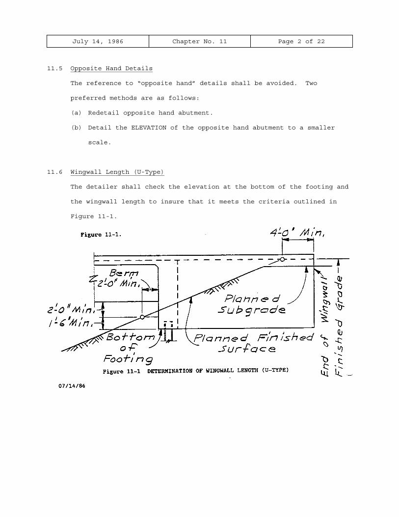
11.6 Wingwall Length (U-Type)
The detailer shall check the elevation at the bottom of the footing and
the wingwall length to insure that it meets the criteria outlined in
Figure 11-1.
July 14, 1986 Chapter No. 11 Page 3 of 22
11.7 Wingwall Designation
It is generally best to designate the wingwall as “Wingwall A, B, C,
and D” rather than Left Wingwall Abutment 1, etc.
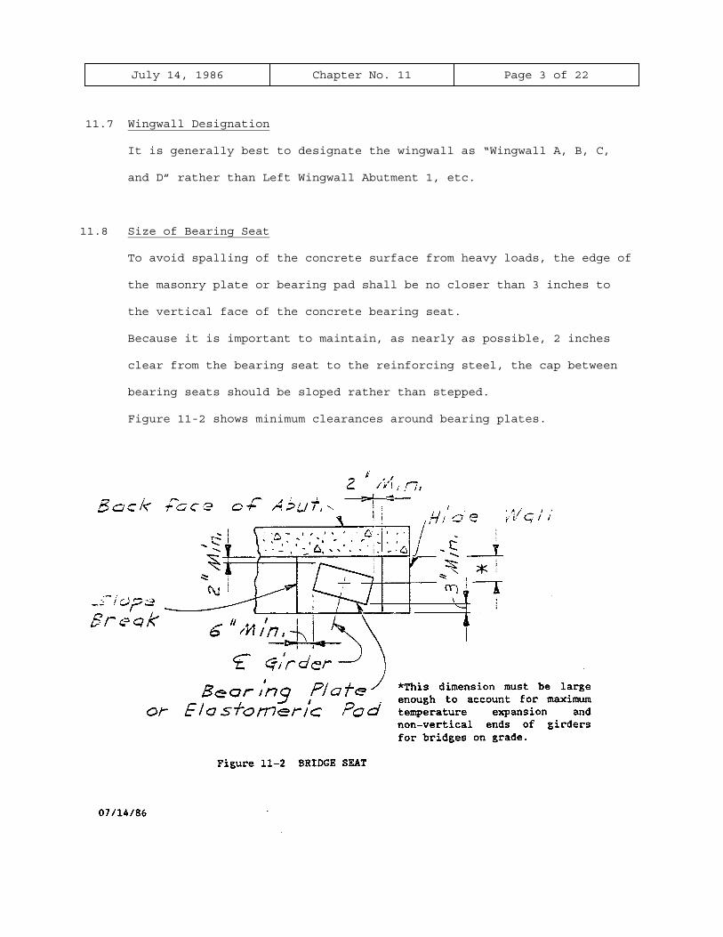
11.8 Size of Bearing Seat
To avoid spalling of the concrete surface from heavy loads, the edge of
the masonry plate or bearing pad shall be no closer than 3 inches to
the vertical face of the concrete bearing seat.
Because it is important to maintain, as nearly as possible, 2 inches
clear from the bearing seat to the reinforcing steel, the cap between
bearing seats should be sloped rather than stepped.
Figure 11-2 shows minimum clearances around bearing plates.

July 14, 1986 Chapter No. 11 Page 4 of 22
11.9 Horizontal Control Line
The horizontal control line shall be shown on the PLAN and labeled
consistently with the plans. Example: “Survey Line,” “Project Line,”
etc.
11.10 Layout Line
For structures on tangent, the layout line and the horizontal control
line will coincide.
For structures located on a curve, the layout line shall be shown on
the PLAN and labeled consistently with the plans. Example: “Tangent
from T.S. Sta. 31+41.08,” “Chord from P.O.C. Sta. 38+41.00 to P.T. Sta.
39+78.00,” “Tangent from P.O.C. Sta. 382+10.00,” etc.
11.11 Stationing
A station shall be placed at the intersection of the horizontal control
line with the centerline of bearings.
All stations on the “Abutment Details” shall be given to two decimal
places.
The direction of stationing shall be indicated on the plan view as
“Station Ahead.”
July 14, 1986 Chapter No. 11 Page 5 of 22
11.12 Centerlines
Centerlines shall be identified and shown as discussed in the following
sections:
(a) Location - Centerlines shall be shown at the following locations,
when applicable:
1. Plan View
(a)Centerline of all girders
(b)Centerline of bearings
(c)Centerline of roadway
(d)Typical centerline of anchor bolts or bearing pads.
2. Section Through Abutment
(a)Centerline of bearings
(b)Identification - The centerlines shown on the abutment
details shall be identified in the following ways:
1. Centerline of Girder - A circle containing the capital
letter G and girder number is placed at the end of each
outside girder centerline, as shown in the PLAN views of
the abutments in the graphic examples. These girder
numbers shall correspond to those shown on the
“Construction Layout.”
2.Other Centerlines - When it is applicable to identify some
of the other centerlines, it should be done by using their
particular names. Example: Centerline Bearings,
Centerline Anchor Bolts, etc.
July 14, 1986 Chapter No. 11 Page 6 of 22
11.13 Elevations
All elevations shown on the “Abutment Details” shall be to two decimal
places. Example: Elev. 47.25, except bottom of footings, which shall
be to one decimal place. Example: Elev. 4647.3.
(a) Location - Elevations shall be shown on the ELEVATION view of the
abutment at the following locations, when applicable:
1. Top of bearing seats, except cast-in-place girder.
2. Bottom of abutment footing, bottom of wingwalls, and bottom of
retaining wall footings, note if level. Except in extreme
situations, the height of abutments and wingwall’s shall be
constant.
11.14 Dimensions
A sufficient number of dimensions shall be shown on the details to
provide adequate information necessary in the checking of the plans and
the construction of the abutment.
For clarification a work point may be accentuated by small circle with
a line extended through the work point or points.
All dimensions shall be given in feet and inches (to the nearest 1/8
inch) except as noted.
(a) Plan of Abutment
1. For structures on a curve, a reference shall be made to the
intersection of the Layout Line and the centerline of abutment
bearings. Example: “538.12’ back on tangent from T.S. Sta.
31+41.08,” “143.69’ ahead on tangent from P.O.C. Sta.
382+10.00,” etc.
2. Outside of deck to outside of deck, along centerline of
bearings.

July 14, 1986 Chapter No. 11 Page 7 of 22
11.14 Dimensions (continued)
3. Horizontal Control Line to outside of deck, along centerline of
bearings, for structures on tangent alignment.
4. Layout Line to outside of deck, along centerline of bearings,
for structures located on a curve.
5. Horizontal Control Line to centerline of the adjacent girders,
along centerline of bearings for structures on tangent
alignment (nearest thousandth of a foot.)
6. Layout Line to centerline of adjacent girders, along centerline
of bearings, for structures located on a curve (nearest
thousandth of a foot).
7. Centerline of girder to centerline of girder, along centerline
of bearings (nearest thousandth of a foot.)
8. Layout Line to Horizontal Control Line, along centerline of
bearings, for structures located on a curve (nearest hundredth
of a foot).
9. Structures which are skewed or structures located on a curve,
show the wingwall offset from outside of bridge deck at
centerline of bearings to outside of bridge deck at the end of
wingwalls, parallel to centerline of bearings.
10. Locate abutment stirrups and give the spacing, along the
centerline of bearings.
11. Centerline of girder to centerline of anchor bolts, measured
normal to the centerline of girder.
12. Typical bearing seat width.
13. Centerline of utility blockout to centerline of nearest girder
and width of blockout, measured normal to the centerline of
blockout.
July 14, 1986 Chapter No. 11 Page 8 of 22
11.14 Dimensions (continued)
14. Length of wingwalls from centerline of bearing to end of
wingwall, along outside of deck.
15. Hidewall width.
(b) Elevation of Abutment
1. Bearing seat to centerline of utility blockout.
(c) Typical Section Through Abutment
1. Projection of piling into the concrete
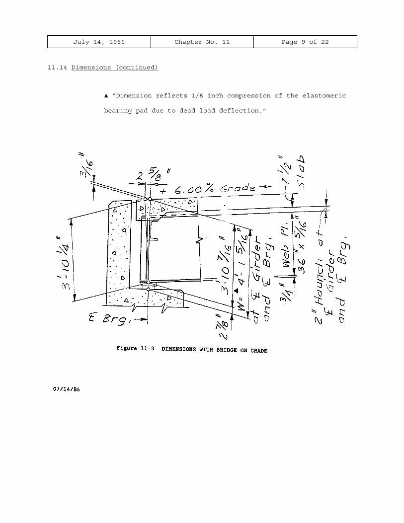
2. The vertical distance, from the top of concrete deck to the
bearing seat measured at the centerline of girder and
centerline of bearings (to the nearest 1/16 inch)
Slab, haunch, bearing device, and cast-in-place girders shall
be measured vertically.
Welded plate girders, wide flange girders, and precast girders,
shall be measured normal to the girder.
In some instances, the roadway grade may be severe enough to
make a difference in the vertical dimension. If this
difference is equal to or greater than 1/16 inch, it shall be
included in the dimension.
An example of the preceding statements is shown in Figure 11-3.
When using elastomeric bearing pads which are greater than 1-
1/2 inch, the designer shall calculate the vertical adjustment
for dead load, which shall be reflected in the dimension W.
The following note is required if the compression of the pad is
1/8 inch or larger.
July 14, 1986 Chapter No. 11 Page 9 of 22
11.14 Dimensions (continued)
▲ “Dimension reflects 1/8 inch compression of the elastomeric
bearing pad due to dead load deflection.”
July 14, 1986 Chapter No. 11 Page 10 of 22
11.14 Dimensions (continued)
3. Width and depth of notch for approach slab.
4. Abutment with constant width
(a) Back face of abutment to centerline of bearing
(b) Centerline of bearing to front face of abutment
(c) Back face of abutment to front face of abutment
5. Abutment with spread footing
(a) Back of footing to back face of abutment
(b) Back face of abutment to front face of parapet
(c) Front face of parapet to centerline of bearing
(d) Centerline of bearing to front face of abutment
(e) Front face of abutment to front face of footing
(f) Footing width
(g) Footing thickness
6. Minimum footing cover
7. Minimum berm width
8. Clearance to bottom reinforcing steel
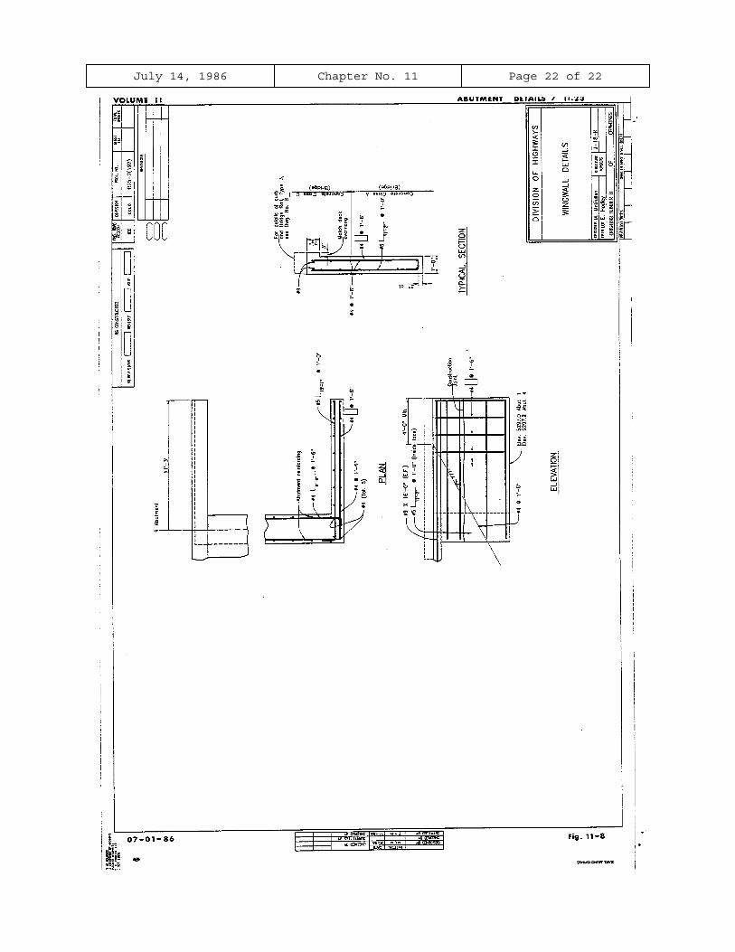
(d) Wingwall Details
1. End of wingwall to centerline of abutment bearings along
outside edge of deck (if the wingwall details are not on the
same sheet as the plan and elevation of the abutment).
2. Width of curb or concrete bridge rail
3. Width of wingwall
4. Width of deck cantilever
5. Thickness of slab at outside of deck.

July 14, 1986 Chapter No. 11 Page 11 of 22
11.14 Dimensions (continued)
6. Fillet dimension at the acute wingwall of abutments where the
skew angle is less than 70º.
7. Dimensions from the end of wingwall to the intersection of
slope; “4’-0” (Min.)” generally.
8. Clearance to bottom reinforcing steel.
11.15 Angles
The following angles shall be shown to the nearest second in the PLAN
view of the abutment, when applicable:
(a) Skew angel (nearest second).
(b) Angles that the girders generate with the centerline for
abutment bearings, if they are different than the skew angle.
(nearest minute).
(c) Angles that the wingwalls generates with the centerline of
abutment bearings, if they are different than the skew angle.
(Nearest Minute)
11.16 Anchor Bolts
When applicable, anchor bolts shall be shown in the PLAN of the
abutment or in a separate detail. The skew angle shall be shown to
the nearest minute. See anchor bolt note.
11.17 Leveling Pads
Elastomeric leveling pads used with precast concrete girders or
steel girders, which are cast-in the abutment, will require an
additional, enlarged detail showing the location of the leveling pad
July 14, 1986 Chapter No. 11 Page 12 of 22
11.17 Leveling Pads (continued)
and the limits of the expansion joint material around it. The skew
angle shall be shown to the nearest minute.
11.18 Piling
When applicable, piling shall be shown, but not dimensioned, in the
PLAN, ELEVATION, and SECTION of the abutment.
11.19 Reinforced Concrete Details
The reinforced concrete details shall be made in accordance with the
design notes and current standard practice. Wingwalls will generally
be designed in accordance with Staff Bridge Design Memo 420-1.
As much of the reinforcing as possible should be called out in section
and details shown to clearly indicate the location of the individual
bars as required in the other views. It should be clear where the
first bar starts and the last bar ends. The length of embedment or
projection for dowels shall be determined by the designer and shown on
the plans. All stirrups should be made the same length, making splices
in legs over length.
All reinforcing steel in the abutment and wingwalls shall be epoxy
coated, with the exception of reinforcing steel which is entirely with-
in a speaded footing. This steel may be non epoxy-coated and so
indicated with the symbol (N).
The statements listed below are to be followed when applicable:
(a) Fit and clearance of reinforcing shall be carefully checked by
calculations, large scale drawings, or other accurate means.
Allowance should be made for the deformations (ridges) on the
reinforcing steel.
Some of the common areas of interference are:
July 14, 1986 Chapter No. 11 Page 13 of 22
11.19 Reinforced Concrete Details (continued)
1. Slab reinforcing and abutment reinforcing
2. Wingwall reinforcing and abutment reinforcing
3. Wingwall reinforcing and girders, for structures with
skews less than 70º.
4. The areas near expansion devices.
Skews will tend to aggravate problems of reinforcing
fitting.
(b) Utility blockouts shall be shown and located in the PLAN and
ELEVATION views of the abutment. An additional detail, showing
the #5 stirrups spaced 6 inches clear of the back face and 4
inches clear of the front face will be required. For additional
information, see Staff Bridge Design Memo 800-2.
(c) On wingwall details “inside face” and “outside face” are
preferred over “N.F.”, “F.F.” when calling out reinforcing.
Refer to the appropriate section of Chapter 4 for additional information
concerning bar clearances, spacing, splicing, embedment, projections,
etc.
11.20 Miscellaneous Concrete Details
The following details shall be shown on the drawing when applicable:
(a) The footings shall be shown in the PLAN, ELEVATION, and SECTION
Views of the abutment.
(b) Approach slabs will be required for continuous structures, with
the girders cast-in the abutments, and a length of 250 feet or
more. Check to see that there is adequate (2” min.) concrete
cover between the notch for the approach slab and the end of
girders, this problem is aggravated by the skew and the roadway

July 14, 1986 Chapter No. 11 Page 14 of 22
11.20 Miscellaneous Concrete Detail (continued)
grade. If a problem does occur, it can usually be solved by
adding a corbel to the back face of the abutment.
(c) Sidewalks shall be continued beyond the abutments to the ends of
wingwalls.
(d) Waterstop should be used between wingwalls and retaining walls.
(e) The expansion device, with anchorage, shall be shown in the
TYPICAL SECTION. Check the width of the parapet to insure
adequate fit. For additional information, see Staff Bridge
Design Memo 518-1.
(f) A 1 1/2” x 1 1/2” fillet will be required at the back face of
the abutment if the abutment concrete is at finished grade and
there is no approach slab, or if there is no asphalt and no
approach slab.
(g) The division of concrete classes shall be shown on the TYPICAL
SECTION and on the wingwall retaining wall ELEVATION. If the
division is shown on the wingwall section a note will be required
to better define where this change occurs. “Construction joint
is at the exterior bearing seat elevation.”
11.21 Check Items
Listed below is a summary of items that shall be checked and appear on
the drawing, when applicable. Additional information shall appear, as
required.
(a) Project number in proper location
(b) Horizontal Control Line, in the PLAN view
(c) Layout Line, in the PLAN view
(d) Stationing
(e) Location and identification of centerlines
(f) Elevations
July 14, 1986 Chapter No. 11 Page 15 of 22
11.21 Check Items (continued)
(g) All necessary dimensions
(h) Skew angle of bridge and other pertinent angles
(i) Anchor Bolts or Leveling Pads
(j) Show footings in the PLAN view as well as in the ELEVATION and
SECTION.
(k) Check all intersecting planes of reinforcing steel for the proper
clearances.
(l) Check expansion device to insure that it fits properly at the
abutment
(m) Check bearing plates, anchor bolts, and girders to insure that
they fit properly at the abutment. See Figures 11-2 and 11-3.
(n) Title PLAN, ELEVATION, and SECTIONS in accordance with their
particular conditions.
(o) Label back face abutments in the PLAN and TYPICAL SECTION.
(p) Label centerline of bearings.
(q) Check for typical notes.
(r) Check title block for information
11.22 Title Block
This drawing is titled “ABUTMENT DETAILS” and shall be so indicated in
the title block. The abutment numbers shall be included in the title,
such as “ABUTMENT 1 AND 3 DETAILS.”
If other details are combined on this drawing, they shall be indicated
in the title. Example: If the “Pier Details” are placed on this
drawing with the “Abutment Details,” the title shall be “ABUTMENT 1 AND
3 DETAILS - PIER 2 DETAIL.”
July 14, 1986 Chapter No. 11 Page 16 of 22
11.22 Title Block (continued)
The structure numbers and the first initial and last name of the
designer and detailer shall be filled in one each sheet.
11.23 Typical Notes
The following notes shall appear on the drawing when applicable:
(a) Utility Blockout Note - “Centerline ___________X___________
Blockout. Cut longitudinal reinforcing and move stirrups to
clear.”
(b) Anchor Bolt Note - “Anchor Bolt ________” Φ X _____ Long.
(Project _____”)”
(c) Abutments with expansion devices - “Concrete above the
construction joint shall be placed after the slab has been
poured. Top of abutment backwall to match slope and grade of the
roadway. For details of expansion device, see Dwg. No. B _____.”
(d) Abutment with elastomeric bearing pads greater than 1 1/2”
Dimension reflects _____, compression of the elastomeric bearing
pad due to dead load deflection.”
(e) Cast-in-place Post Tensioned Bridges “Slope paving in front of
abutments to be placed after stressing.”
(f) Precast G-54, G-68, or G-72 girders
1. “4” Fillet (Typ. Between girders).”
2. “Field bend or cut reinforcing to provide 2” cl. At bearing
seats.”
3. “Slab and portion of abutment above bearing seat to be
poured monolithically.”
(g) Wingwall Details
1. “For details and reinforcing of curb, and details of Bridge
Rail Type 3, see Dwg. No. B _____.”
July 14, 1986 Chapter No. 11 Page 17 of 22
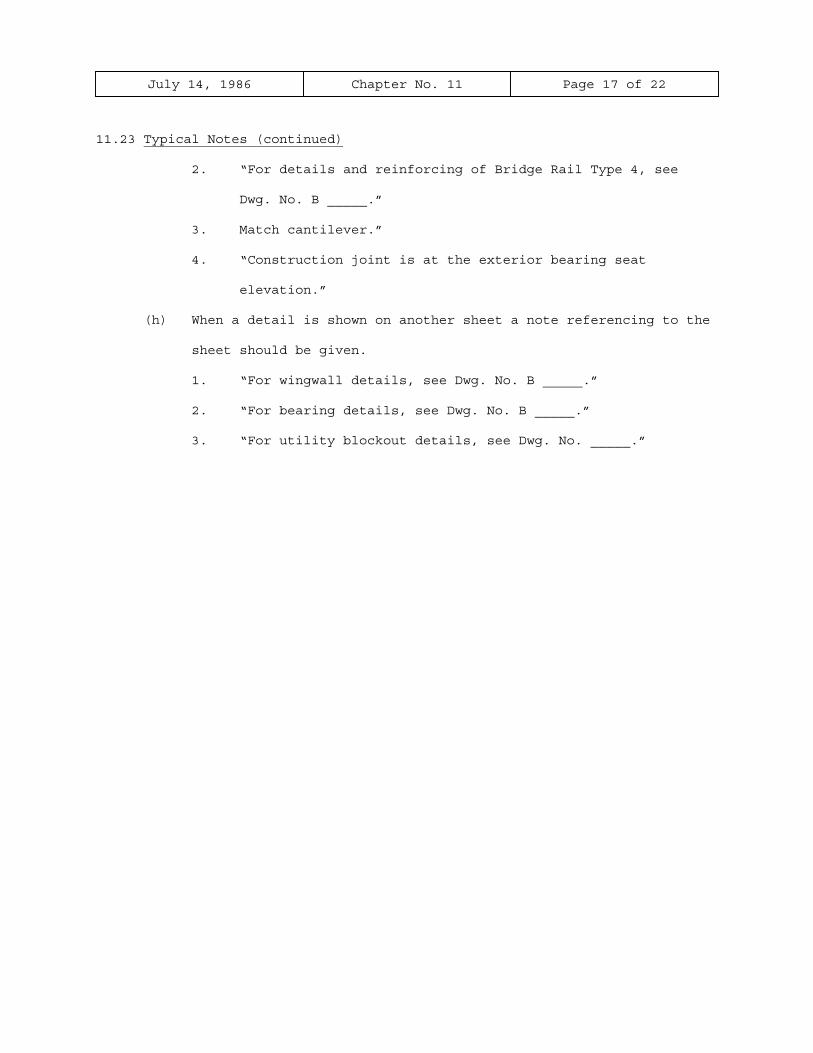
11.23 Typical Notes (continued)
2. “For details and reinforcing of Bridge Rail Type 4, see
Dwg. No. B _____.”
3. Match cantilever.”
4. “Construction joint is at the exterior bearing seat
elevation.”
(h) When a detail is shown on another sheet a note referencing to the
sheet should be given.
1. “For wingwall details, see Dwg. No. B _____.”
2. “For bearing details, see Dwg. No. B _____.”
3. “For utility blockout details, see Dwg. No. _____.”
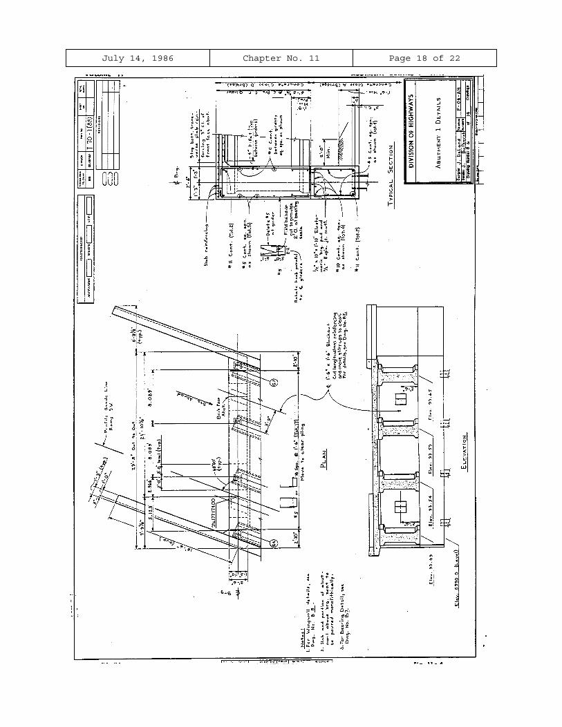
July 14, 1986 Chapter No. 11 Page 18 of 22
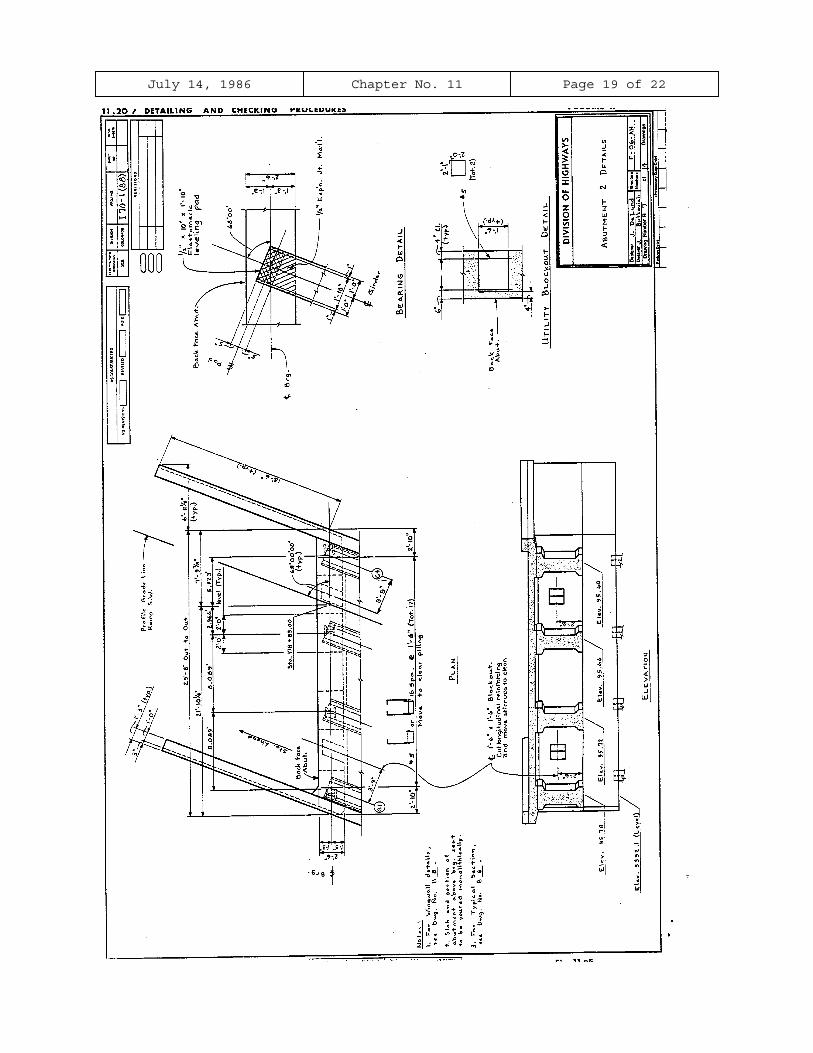
July 14, 1986 Chapter No. 11 Page 19 of 22
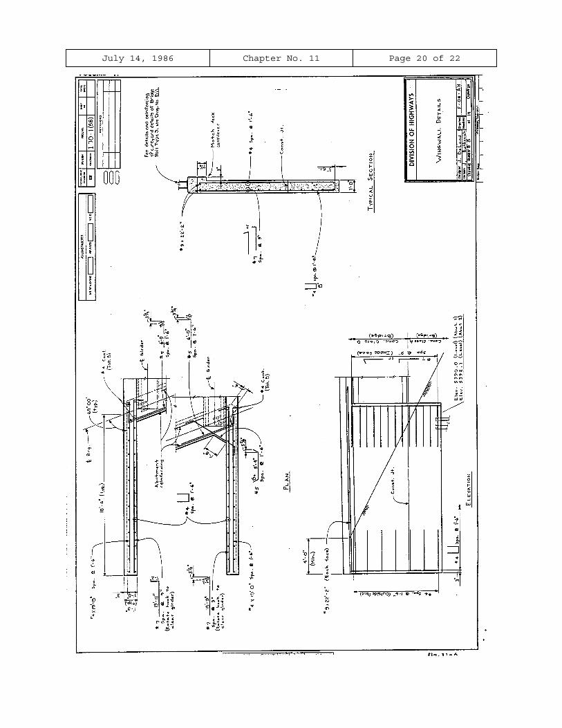
July 14, 1986 Chapter No. 11 Page 20 of 22

July 14, 1986 Chapter No. 11 Page 21 of 22
July 14, 1986 Chapter No. 11 Page 22 of 22