100k q-factor toroidal ring gyroscope implemented …
TRANSCRIPT

100K Q-FACTOR TOROIDAL RING GYROSCOPE
IMPLEMENTED IN WAFER-LEVEL EPITAXIAL SILICON
ENCAPSULATION PROCESS D. Senkal1, S. Askari1, M.J. Ahamed1, E.J. Ng2, V. Hong2, Y. Yang2, C.H. Ahn2, T.W. Kenny2, A.M. Shkel1
1University of California, Irvine, California, USA 2Stanford University, Palo Alto, California, USA
ABSTRACT
This paper reports a new type of degenerate mode gyroscope with measured Q-factor of > 100,000 on both modes at a compact size of 1760 µm diameter. The toroidal ring gyroscope consists of an outer anchor ring, concentric rings nested inside the anchor ring and an electrode assembly at the inner core. Current implementation uses n = 3 wineglass mode, which is inherently robust to fabrication asymmetries. Devices were fabricated using high-temperature, ultra-clean epitaxial silicon encapsulation (EpiSeal) process. Over the 4 devices tested, lowest as fabricated frequency split was found to be 8.5 Hz (122 ppm) with a mean of 21 Hz (Δf/f = 300 ppm). Further electrostatic tuning brought the frequency split below 100 mHz (< 2 ppm). Whole angle mechanization and pattern angle was demonstrated using a high speed DSP control system. Characterization of the gyro performance using force-rebalance mechanization revealed ARW of 0.047°/√hr and an in-run bias stability of 0.65 deg/hr. Due to the high Q-factor and robust support structure, the device can potentially be instrumented in whole angle mechanization for applications which require high rate sensitivity and robustness to g-forces.
INTRODUCTION Coriolis Vibratory Gyroscopes (CVGs) can be divided
into two broad categories [1] based on the gyroscope’s mechanical element: Degenerate mode gyroscopes which have x-y symmetry (Δf = 0 Hz ideal) and non-degenerate mode gyroscopes which are designed intentionally to be asymmetric in x and y modes (Δf ≠ 0 Hz). Degenerate mode CVGs have potential advantages over non-degenerate mode CVGs in terms of rate sensitivity, signal to noise ratio, power consumption, and potential to implement whole angle mechanization [2]. However, mechanical elements with high-Q factor and very good frequency symmetry are required to utilize these advantages.
Realizing this potential, many MEMS degenerate mode gyroscopes emerged in the recent years. For example, high aspect ratio ring gyroscopes have been demonstrated in [3]. A cylindrical rate integrating gyroscope with a Q-factor of ~21,800 at 2.5 mm diameter was demonstrated in [4], a high frequency poly-silicon disk resonator gyroscope (DRG) [5] with a Q-factor of ~50k at 264 kHz and 600 µm diameter was presented in [6], later a crystalline-silicon version of similar geometry was demonstrated with Q-factor ~100k in [7]. Q-factors as high as 1 million was demonstrated on a quadruple mass gyroscope (QMG) [8], however the device had a 9 mm x 9 mm footprint. Despite these successful implementations
of degenerate mode operation, obtaining a high-Q factor in a compact volume remains to be a challenge due to factors such as support losses, thermo-elastic dissipation, and viscous damping.
In this paper, we present an epitaxial silicon encapsulated [9] toroidal ring gyroscope with a robust outer perimeter anchor and a distributed suspension system [10]. In contrast to axi-symmetric designs with central support structures, such as [3-7], we explore an alternative support structure for anchor loss minimization. The vibrational energy in the introduced design is concentrated towards the innermost ring, and the device is anchored at the outer perimeter. The distributed support structure prevents vibrational motion propagating to the outer anchor, which helps trap the vibrational energy within the gyroscope providing a Q-factor of > 100,000 at a compact size of 1760 µm.
The toroidal ring gyroscope was fabricated using a wafer-level epitaxial silicon encapsulation process (EpiSeal) [9]. EpiSeal process utilizes epitaxially grown silicon to seal the device layer at extremely high temperatures, which results in an ultra-clean wafer-level seal. This results in high vacuum levels (as low as 1 Pa [9]) without the need for getter materials for absorption of sealing by-products. Due to the high Q-factor and robust support structure, the device can potentially be instrumented in high-g environments that require high angular rate sensitivity.
In the next section, we will present design of toroidal ring gyroscope. This will be followed by experimental characterization of the mechanical element and implementation of force rebalance as well as whole angle mechanizations. The paper concludes with a discussion of the results.
Diameter = 1760 µm 250 µm
Ring anchor
DC quad. electrode
Electrodes x 12
Capacitive gap
Suspension system
Figure 1: Toroidal ring gyroscope consists of an outer ring
anchor, distributed suspension system and inner electrodes.
978-1-4799-3509-3/14/$31.00 ©2014 IEEE 24 MEMS 2014, San Francisco, CA, USA, January 26 - 30, 2014

Figure 2: Due to the distributed suspension system
vibrational energy is trapped within the gyroscope.
DESIGN Toroidal ring gyroscope consists of an outer anchor that
encircles the device, a distributed ring support structure and an inner electrode assembly, Fig. 1. As opposed to axi-symmetric devices with central support structures [3-7], vibration energy is concentrated at the innermost ring, Fig. 2. The distributed support structure [10] decouples the vibrational motion from the substrate, Fig. 2. This decoupling mitigates anchor losses into the substrate and prevents die/package stresses from propagating into the vibratory structure.
The device was fabricated on single-crystal <100> silicon wafers. For this reason device was designed to operate in n = 3 wineglass modes instead of the more commonly used lower order n = 2 wineglass modes. This eliminates frequency split induced by anisotropic modulus of elasticity of crystalline silicon and makes the frequency splits (Δf) insensitive to misalignment errors in crystalline orientation of the silicon wafer. The draw-back of operation in n = 3 modes are slightly lower angular gain factor, higher resonance frequency and smaller amplitude of motion.
Electrode assembly is located at the center of the gyroscope and consists of 12 discrete electrodes and 1 central electrode, Fig. 3. Discrete electrodes are distributed in groups of 6 onto each degenerate mode. 2 electrodes were used as a forcer and 4 as a pick-off for each mode, giving a total of 4 forcer and 8 pick-off electrodes across the gyro.
The central electrode has two primary functions: (1) it acts as a shield by sinking parasitic currents between adjacent discrete electrodes, (2) it can function as a DC quadrature null electrode as it forms a capacitive gap with the gyroscope at 12 points 15 deg. offset from the discrete electrodes. This eliminates the need for any of the 12 discrete electrodes to be assigned for quadrature null electrodes and hence allows all 12 discrete electrodes to be dedicated as forcer or pick-off.
The device was fabricated on a 2 x 2 mm die, the mechanical element has an outer diameter of 1760 µm and was fabricated on a device layer thickness of 40 µm, Table 1. The suspension system consists of 44 concentric rings. The rings are connected to each other using 12 spokes between
the rings, the spokes are interleaved with an offset of 15 deg. between two consecutive rings. The suspension rings have a thickness of 5 µm. The innermost ring is designed to have a slightly higher ring thickness of 8.5 µm, this mitigates the effect of spokes on the overall mode shape and helps retain a truer wineglass shape at the electrode interface.
RESULTS Devices were wirebonded to ceramic Leadless Chip
Carriers (LCCs) and istrumented with discrete electronics. Electromechanical Amplitude Modulation (EAM) at 1 MHz was used to mitigate the effects of parasitic feed-through on the pick-off electronics. DC bias voltage of 1 V on both modes and AC voltage of 20 mV was used for initial characterization. Frequency response characterization of the fabricated gyroscopes revealed a Q-factor of > 100,000 on both n = 3 modes at ~70 kHz center frequency, Fig. 4.
As-fabricated frequency split (Δf) of 4 devices were characterized. Lowest frequency split observed was at 8.5 Hz, Fig. 3, (Δf/f = 122 ppm) with a mean frequency split of 21 Hz (Δf/f = 300 ppm) across 4 devices, Table 2. Low frequency split is attributed to robustness of the high order (n=3) wineglass mode to fabrication imperfections and the ultra-clean EpiSeal process.
Table 1: Summary of geometric parameters. Device diameter (µm) 1760 Device layer thickness (µm) 40 Capacitive gaps (µm) 1.5 Ring thickness (µm) 5 Innermost ring thickness (µm) 8.5 Number of rings 44
Table 2: As-fabricated frequency symmetry of 4 devices.
Device Δf (Hz) f (kHz) Δf/f (ppm)
#1 8.5 69.75 122 #2 11 69.69 158 #3 25 71.29 350 #4 40 69.4 576
FX(+)
FX(-)
FY(+)
FY(-)
PY(+)
PX(+)
PX(-)
PY(-)
PY(+)PX(+)
PY(-)
DC quadratureelectrode
Forcer
PX(-)Pick-off
Figure 3:Electrode assembly of the toroidal ring gyroscope,
showing pick-off (P) and forcer electrodes (F).
Vibration amplitude (nm) for 200 nm peak displacement
0 > 5010 20 30 40
25

After initial characterization the frequency split was further reduced using electrostatic tuning of DC bias on forcer and quadrature null electrodes. DC bias voltages of 3.26 V and 0.5 V was sufficient to reduce the frequency split to < 100 mHz (Δf/f < 2 ppm) on Device #1, Fig. 5.
Control system
A DSP-based control system was developed for rate and rate integrating operation. Pattern angle control and whole angle operation is enabled by the use of pendulum variables defined by [11], Fig. 6. The key component of this approach is a PLL loop that tracks the gyro motion at any arbitrary pattern angle as opposed to locking onto one of the primary gyro axis. Once the PLL is implemented key system parameters such as amplitude (E), quadrature error (Q), and pattern angle (θ) can be extracted. Three closed loops act on these parameters: Amplitude gain control (AGC) to keep the drive amplitude stable, quadrature null loop to suppress the quadrature component of the vibratory motion, and force rebalance (FRB) loop to control the pattern angle. Once the required drive vector is determined from the AGC, quadrature null and FRB loops a coordinate transformation takes place to align the force vector with the current pattern angle, which later is modulated at the gyro reference frequency and injected into the respective X and Y forcer
electrodes. In this control scheme, disabling the FRB loop allows free precession of the pattern angle, also known as whole angle operation, Fig. 7 (a).
All control algorithms were implemented on an ADAU1442 DSP board from Analog Devices. A 24 bit audio codec (AD1938) operating at 192 kHz sampling rate was used for forcer and pick-off signals. An Arduino Due micro-controller board was interfaced with the DSP board over I2S protocol, which was used to down-sample the gyro output and transmit over RS232 protocol for data acquisition.
Pattern angle dependent behaviour of AGC and quadrature null loops as well as error in pattern angle estimation were evaluated through virtual carouseling. Amplitude of the standing wave was kept constant and AGC output was recorded with respect to pattern angle. Due to mismatches in force and pick-off gains a 484 µV std. deviation in AGC output was observed for a mean forcer output of 21.5 mV, Fig. 7(b). For DC quadrature control the output of the quadrature control loop was amplified and fed to the star shaped quadrature null electrode at a slowly varying rate. Instantaneous changes in quadrature error were compensated by using AC quadrature control. Maximum quadrature error was observed at ~45 deg. electrical pattern angle as expected from [11] with a mean value of 512 µV AC, Fig. 8(b).
Accuracy of pattern angle detection was evaluated by
69.7473 69.7523 69.7573-30
-20
-10
0
Frequency (kHz)
Am
pli
tud
e(d
B)
Δ Δf < 100 mHz ( f/f < 2 ppm)
Figure 4: Freq. sweep showing the n=3 wineglass modes
with Q-factor above 100k at central freq. of 69.8 kHz.
Figure 5: Electrostatic tuning with 3.26 V and 0.5 V resulted
in Δf < 100 mHz (Δf/f < 2ppm @ 69.75 kHz).
Figure 6: Whole angle mechanization implemented in DSP,
allowing rate-integrating operation and control of pattern angle.
a) b)
20
40
30
210
60
240
90
270
120
300
150
330
180 0
Figure 7:Demonstration of WA operation: real-time capture
from carouseling (a), AGC output (mV) vs pattern angle (b).
69.7972 69.8072 69.8172-40
-20
0
Frequency (kHz)
Am
pli
tud
e(d
B)
69.7972 69.8072 69.8172-90
0
90
69.7972 69.8072 69.8172-90
0
90
Δf = 8.5 Hz
Q = 110ky Q = 104kx
PL
L&
Dem
od
ula
tio
n
PY
PX
FY
FX
Pen
dulu
m v
aria
ble
s
Mo
du
lati
on
Co
ord
. tr
ansf
orm
atio
ncx
sx
cy
sy
E
Q
θPen
dulu
m v
aria
ble
s AGC
Q. null
FRBFY`
FX`FE
FQ
Fθ
Reference frequency (NCO: sin & cos)
Pattern angle (θ)
26
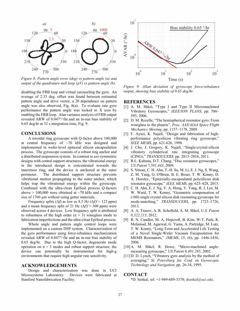
disabling the FRB loop and virtual carouseling the gyro. An average of 2.33 deg. offset was found between estimated pattern angle and drive vector, a 2θ dependence on pattern angle was also observed, Fig. 8(a). To evaluate rate gyro performance the pattern angle was locked to X axis by enabling the FRB loop. Alan variance analysis of FRB output revealed ARW of 0.047°/√hr.and an in-run bias stability of 0.65 deg/hr at 32 s integration time, Fig. 9.
CONCLUSIONS A toroidal ring gyroscope with Q-factor above 100,000
at central frequency of ~70 kHz was designed and implemented in wafer-level epitaxial silicon encapsulation process. The gyroscope consists of a robust ring anchor and a distributed suspension system. In contrast to axi-symmetric designs with central support structures, the vibrational energy in the introduced design is concentrated towards the innermost ring, and the device is anchored at the outer perimeter. The distributed support structure prevents vibrational motion propagating to the outer anchor, which helps trap the vibrational energy within the gyroscope. Combined with the ultra-clean EpiSeal process Q-factors above > 100,000 were obtained at ~70 kHz and a compact size of 1760 µm without using getter materials.
Frequency splits (Δf) as low as 8.5 Hz (Δf/f = 122 ppm) and a mean frequency split of 21 Hz (Δf/f = 300 ppm) were observed across 4 devices. Low frequency split is attributed to robustness of the high order (n = 3) wineglass mode to fabrication imperfections and the ultra-clean EpiSeal process.
Whole angle and pattern angle control loops were implemented on a custom DSP system. Characterization of the gyro performance using force-rebalance mechanization revealed ARW of 0.047°/√hr and an in-run bias stability of 0.65 deg/hr. Due to the high Q-factor, degenerate mode operation on n = 3 modes and robust support structure, the device can potentially be instrumented for high-g environments that require high angular rate sensitivity.
ACKNOWLEDGEMENTS Design and characterization was done in UCI
Microsystems Laboratory. Devices were fabricated at Stanford Nanofabrication Facility.
REFERENCES [1] A. M. Shkel, “Type I and Type II Micromachined
Vibratory Gyroscopes,” IEEE/ION PLANS, pp. 586–593, 2006.
[2] D. M. Rozelle, “The hemispherical resonator gyro: From wineglass to the planets”, Proc. AAS/AIAA Space Flight
Mechanics Meeting, pp. 1157–1178, 2009. [3] F. Ayazi, K. Najafi, “Design and fabrication of high-
performance polysilicon vibrating ring gyroscope,” IEEE MEMS, pp. 621-626, 1998.
[4] J. Cho, J. Gregory, K. Najafi, “Single-crystal-silicon vibratory cylinderical rate integrating gyroscope (CING),” TRANSDUCERS, pp. 2813–2816, 2011.
[5] R.L. Kubena, D.T. Chang, “Disc resonator gyroscopes,” US Patent 7,581,443, 2009.
[6] S. Nitzan, C. H. Ahn, T.-H. Su, M. Li, E. J. Ng, S. Wang, Z. M. Yang, G. O'Brien, B. E. Boser, T. W. Kenny, D. A. Horsley, “Epitaxially-encapsulated polysilicon disk resonator gyroscope,” IEEE MEMS, pp. 625–628, 2013.
[7] C. H. Ahn, E. J. Ng, V. A. Hong, Y. Yang, B. J. Lee, M. W. Ward, T. W. Kenny, “Geometric compensation of (100) single crystal silicon disk resonating gyroscope for mode-matching,” TRANSDUCERS, pp. 1723–1726, 2013.
[8] A. A. Trusov, A. R. Schofield, A. M. Shkel, U.S. Patent
8,322,213, 2012. [9] R. N. Candler, M. A. Hopcroft, B. Kim, W-T. Park, R.
Melamud, M. Agarwal, G. Yama, A. Partridge, M. Lutz, T. W. Kenny, “Long-Term and Accelerated Life Testing of a Novel Single-Wafer Vacuum Encapsulation for MEMS Resonators,” JMEMS, 15, (6), pp. 1446-1456, 2006.
[10] A. M. Shkel, R. Howe, “Micro-machined angle-measuring gyroscope," US Patent 6,481,285, 2002.
[11] D. D. Lynch, “Vibratory gyro analysis by the method of averaging,” St. Petersburg Int. Conf. on Gyroscopic
Technology and Navigation, pp. 26-34, 1995.
CONTACT *D. Senkal, tel: +1-949-689-3370; [email protected].
100
101
102
103
100
101
Time (s)
AV
AR
(°/h
r)
Bias stability 0.65 °/hr
ARW0.047 °/
hr√
Figure 9: Allan deviation of gyroscope force-rebalance
output, showing bias stability of 0.65 deg/hr.
Figure 8: Pattern angle error (deg) vs pattern angle (a) and
output of the quadrature null loop (µV) vs pattern angle (b).
2.5
5
30
210
60
240
90
270
120
300
150
330
180 0
30
210
60
240
90
270
120
300
150
330
180 0
a) b)
500
1000
27