100% submittal technical specification - · pdf file100% submittal technical specification for...
TRANSCRIPT

Prepared By:
100% SUBMITTAL TECHNICAL SPECIFICATION
FOR WASHINGTON UNION STATION
CONCOURSE HVAC EQUIPMENT RELOCATION
JANUARY 19, 2016
NATIONAL RAILROAD PASSENGER CORPORATION 30th Street Station, 4th Fl. North Tower, Philadelphia, PA 19104

TABLE OF CONTENTS
- 1 -
DIVISION 1 – GENERAL REQUIREMENTS 010100 SUMMARY OF WORK 010300 SPECIAL PROJECT PROCEDURES AND SAFETY 013000 SUBMITTALS 013200 PROJECT PHOTOGRAPHS 014000 QUALITY REQUIREMENTS DIVISION 2 – SITE CONSTRUCTION 024116 STRUCTURE DEMOLITION DIVISION 5 – METALS 051200 STRUCTURAL STEEL FRAMING 055000 METAL FABRICATIONS 055213 PIPE AND TUBE RAILINGS 055300 METAL GRATINGS DIVISION 7 – THERMAL AND MOISTURE PROTECTION 072500 WEATHER BARRIERS 075323 ETHYLENE-PROPLYENE-DIENE-MONOMER (EPDM) ROOFING 077100 ROOF SPECIALTIES 077200 ROOF ACCESSORIES DIVISION 21 - FIRE SUPPRESSION 210500.1 COMMON WORK RESULTS FOR FIRE SUPPRESSION 211313 WET-PIPE SPRINKLER SYSTEMS DIVISION 22 – PLUMBING 220500.1 COMMON WORK RESULTS FOR PLUMBING 220523 GENERAL-DUTY VALVES FOR PLUMBING PIPING 220529 HANGERS AND SUPPORTS FOR PLUMBING PIPING 220553 IDENTIFICATION FOR PLUMBING PIPING 220719 PLUMBING PIPING INSULATION 221116 DOMESTIC WATER PIPING 221119 DOMESTIC WATER PIPING SPECIALTIES

TABLE OF CONTENTS
- 2 -
DIVISION 23 – HEATING, VENTILATING AND AIR CONDITIONING 230130.51 HVAC AIR DUCT CLEANING 230500.1 COMMON WORK RESULTS FOR HVAC 230513 COMMON MOTOR REQUIREMENTS FOR HVAC EQUIPMENT 230519 METERS AND GAGES FOR HVAC PIPING 230523.11 GLOBE VALVES FOR HVAC PIPING 230523.12 BALL VALVES FOR HVAC PIPING 230523.13 BUTTERFLY VALVES FOR HVAC PIPING 230523.14 CHECK VALVES FOR HVAC PIPING 230523.15 GATE VALVES FOR HVAC PIPING 230523.16 PLUG VALVES FOR HVAC PIPING 230529 HANGERS AND SUPPORTS FOR HVAC PIPING AND EQUIPMENT 230533 HEAT TRACING FOR HVAC PIPING 230548 VIBRATION CONTROLS FOR HVAC PIPING AND EQUIPMENT 230553 IDENTIFICATION FOR HVAC PIPING AND EQUIPMENT 230593 TESTING, ADJUSTING, AND BALANCING FOR HVAC 230713 DUCT INSULATION 230716 HVAC EQUIPMENT INSULATION 230719 HVAC PIPING INSULATION 230800 COMMISSIONING OF HVAC 230900 INSTRUMENTATION AND CONTROL FOR HVAC 232113 HYDRONIC PIPING 232116 HYDRONIC PIPING SPECIALTIES 232123 HYDRONIC PUMPS 232213 STEAM AND CONDENSATE HEATING PIPING 232223 STEAM CONDENSATE PUMPS 232500 HVAC WATER TREATMENT 233113 METAL DUCTS 233300 AIR DUCT ACCESSORIES 234100 PARTICULATE AIR FILTRATION 234200 ULTRA VIOLET GERMICIDAL IRRADIATION (UVGI) SYSTEM 235700 HEAT EXCHANGERS FOR HVAC 237313 MODULAR CENTRAL-STATION AIR-HANDLING UNITS 238216 AIR COILS DIVISION 26 – ELECTRICAL 260519 LOW-VOLTAGE ELECTRICAL POWER CONDUCTORS AND CABLES 260523 CONTROL VOLTAGE ELECTRICAL POWER CABLES 260526 GROUNDING AND BONDING FOR ELECTRICAL SYSTEMS 260529 HANGERS AND SUPPORTS FOR ELECTRICAL SYSTEMS 260533 RACEWAY AND BOXES FOR ELECTRICAL SYSTEMS 260553 IDENTIFICATION FOR ELECTRICAL SYSTEMS 262200 LOW-VOLTAGE TRANSFORMERS 262413 SWITCHBOARDS 262416 PANELBOARDS 262713 ELECTRICITY METERING

TABLE OF CONTENTS
- 3 -
262726 WIRING DEVICES 262813 FUSES 262816 ENCLOSED SWITCHES AND CIRCUIT BREAKERS 262913 ENCLOSED CONTROLLERS 262923 VARIABLE FREQUENCY MOTOR CONTROLLERS 265100 INTERIOR LIGHTING

SECTION 010100
SUMMARY OF WORK
January 2016 010100-1 Amtrak WUS Concourse Phase 1a 100% Submittal HVAC Equipment Relocation
PART 1 - GENERAL
1.1 GENERAL DESCRIPTION OF WORK
A. Amtrak is making major improvements in a section of the Northeast Corridor (NEC) within the State of New Jersey through the New Jersey High-Speed Rail Improvement Program (NJ HSRIP). These improvements are multi-disciplinary, multi-system in nature, and include track improvements for increased speeds, increased power supply, renewal of the overhead contact system, construction of new interlockings, the installation of new signal power equipment, and new signalization. A major component of this program is the addition of new 25 Hz generation to supplement the existing motor-generator at PSE&G’s facility in Edison, New Jersey. A recent study has shown that the Metuchen area would be an ideal location to supplement this facility with an extra 60 MW of power. Two new 30 MW identical converters shall be required to share the load with the existing motor-generator unit that PSE&G currently owns and operates and be integrated to function with the rest of the frequency converters and water wheels on the Amtrak system. The new frequency converters shall be required to operate both independently and in parallel with each other, including an existing 25 MW motor-generator (MG) set, also referred to as a rotary frequency converter (RFC). This RFC is supplied from a different 60 Hz source, but supplies the same 13.2 kV, 25 Hz, single-phase bus that shall be common to the new frequency converters. In the near future, this existing RFC shall be uprated to approximately 115% of its present capacity, or 1.15 x 25 MW = 28.75 MW.
B. The Contractor shall be responsible for design, engineering, fabrication, site work, construction, testing, delivery and commissioning of equipment, material and facilities including the 2 x 30 MW Static Frequency Converter (SFC) "power block" from the 230 kV cable termination at the PSE&G 230 kV switchyard to the output 13.2 kV cable terminations on Amtrak’s 13.2 -138 kV Step-Up yard built under a separate project. The Contractor shall coordinate the SFC design and installation with the installation of Amtrak’s Step-Up yard.
C. It is the responsibility of the Contractor to gather all data necessary for the performance of the Work under this Contract and to develop a complete and final design. Amtrak will furnish the Contractor with Contract Documents, which include Design Criteria, applicable Amtrak Standards, Technical Specifications Divisions 2 through 16, and Project Drawings for the Contractor’s use in developing Final Design Specifications and Final Design Drawings.
D. Amtrak will furnish, if applicable, to the Contractor awarded the contract, without charge, one (1) set of CD ROM discs in an AutoCAD (.DWG) file format of the original Proposal Set Project Drawings including any amendments and one (1) set of CD ROM disks of the original Proposal Set specifications including any amendments in current Word version, except for the applicable publications referenced in the technical provisions. Additional documents shall be furnished on request at the cost of reproduction.
E. The Contractor shall produce Final Design Specifications and Final Design Drawings, Shop and Working Drawings, Contract Record Drawings and Specifications, and other Contract Documents in the appropriate medium.
1. The Final Design and As-Built Specifications shall be in Construction Specifications Institute (CSI) Format (latest edition) per Amtrak's requirements.
2. The Final Design, Shop, Working, and Contract Record Drawings shall be produced in an AutoCAD (.DWG) format and line work shall be shown on designated layers in accordance with the standard CAD guidelines as specified in Section 01300. Images shall be clear, sharp and readily legible. For updates to As-Built Drawings, drafting

SECTION 010100
SUMMARY OF WORK
January 2016 010100-2 Amtrak WUS Concourse Phase 1a 100% Submittal HVAC Equipment Relocation
quality shall match the original documents in line weights, symbols and lettering style and size.
F. By providing Amtrak’s Design Criteria, Amtrak does not relieve the Contractor of its complete responsibility for the adequacy of the design. Accordingly, the Contractor must verify that existing site conditions described in the Contract Documents are current and verify all design elements to ensure that the Final Design Specifications and the Final Design Drawings are consistent with the applicable codes and regulations adopted by the governing jurisdictional agencies. In the event that Amtrak’s Design Criteria exceeds applicable codes and regulations, the Contractor shall be responsible for providing a design that is consistent with Amtrak’s Design Criteria.
G. All work under this Contract shall be performed in accordance with the terms and conditions of the Contract and in a logical sequence as developed by the Contractor. The COTR reserves the right to review and approve the sequence of work.
H. Portions of the Contract work will be performed in close proximity to Amtrak and/or PSE&G facilities. All work shall be performed in accordance with safety regulations of both companies and shall be scheduled to avoid disruptions of service to the operations of either company.
1.2 PROJECT MANAGEMENT AND COORDINATION
A. For detailed Project Management details refer to Specification Section 01401.
1.3 PROJECT INFORMATION
A. Project Identification: Metuchen Frequency Converter
1. Project Location: 234 Pierson Ave in Edison NJ
B. Owner: National Railroad Passenger Corporation (Amtrak).
1. Project Engineer: Project Engineer’s status relative to the construction/design shall be delineated in writing by the Contracting Officer after the Project is awarded. Where the Specifications refer to the Owner/Amtrak, it shall mean the Project Engineer.
C. Definitions:
1. Contractor: The Contractor who is responsible for the final engineering design, supply of equipment, installation, and commissioning of the Metuchen Station SFC facility.
2. Utility: Public Service Electric and Gas (PSE&G)
3. Converter Vendor: Entity providing the frequency converter equipment, who may be a subcontractor to the primary Contractor.
4. COR: Amtrak's Contracting Officer's Representative
5. 230 kV point of connection: The termination of the frequency converter 230 kV cables to the PSE&G 60 Hz breaker-and-a-half bay in the PSE&G 230 kV switchyard.
6. 13.2 kV point of connection: The termination of the frequency converter 13.2 kV cables or bus duct to the Amtrak 13.2 kV switchyard bus.
7. Converter: Refers to either a static frequency converter or motor-generator (M-G) set
8. SFC: Static frequency converter
9. M-G: Motor-generator, also referred to as a rotary converter
10. TBD: To be determined

SECTION 010100
SUMMARY OF WORK
January 2016 010100-3 Amtrak WUS Concourse Phase 1a 100% Submittal HVAC Equipment Relocation
11. Distortion: Ratio of the RMS of the harmonic content to the RMS value of the fundamental quantity expressed as a percent of the fundamental. The distortion shall include integer harmonics, non-integer harmonics, and subharmonics.
12. Equal or Approved Equal: A satisfactory equivalent as approved by the COTR. The Contractor shall submit pertinent data, references and quoted cost savings to the COTR for approval.
13. Harmonic: A sinusoidal component of a periodic wave or quantity having a frequency that is an integral multiple of the fundamental frequency
14. IFD: Individual frequency distortion
15. Integer Harmonic: Integer multiple of fundamental frequency
16. Jobsite: Amtrak's property on which the equipment and materials provided under this Contract will be installed.
17. Non-Integer Harmonic: Non-integer multiple of fundamental frequency
18. PSE&G: Public Service Electric and Gas
19. Power Block: A complete SFC system including input transformers, input filters, static frequency converter, output filters, output transformers and all power connections between associated equipment.
20. Power Factor (pf): The term "power factor" and the notation "pf" refer to the displacement power factor at the fundamental frequency. Refer to IEEE 519 for a complete definition of displacement power factor. Specifically, the power factor is determined from the fundamental wave. For all references within this specification utilizing the terms "power factor" or "pf" it is intended that the values correspond to the fundamental frequency. The power factor requirements for this specification section are shown in the PQ Curve in Section 16262.
21. Power Plant Equipment: All the material and equipment specified herein that shall be provided by the Vendor and installed under the Vendor’s supervision by the Contractor.
22. SFC Unit: The static frequency converter including input & output transformers and filters.
23. Static Frequency Converter: A thyristor phase-controlled converter consisting of solid state semi-conductor switching devices such as conventional or gate turn-off (GTO) thyristors.
24. Station (or Plant): All equipment and structures which constitute a completely operational facility.
25. Subharmonics: Those harmonics below the fundamental frequency (includes integer and non-integer divisors of the fundamental).
26. THD: Total harmonic distortion
27. Black Start: The process of restoring power to the 25 Hz system without relying on voltage from the 25 Hz system. A SFC that has black start capability shall be able to energize and provide power to the 25 Hz system at a frequency of 25 Hz without relying on any other 25 Hz power sources. During black start, only the 60 Hz utility power system is available.
28. SF6: Sulfur-hexafluoride.
29. SCADA: Supervisory control and data acquisition.
30. COTR: Contracting Officer’s Technical Representative.

SECTION 010100
SUMMARY OF WORK
January 2016 010100-4 Amtrak WUS Concourse Phase 1a 100% Submittal HVAC Equipment Relocation
1.4 DIVISION OF WORK RESPONSIBILITY
A. All Construction activities described in the Contract Documents, unless otherwise indicated, shall be performed by the Contractor.
1. The Contractor shall furnish all tools, equipment, labor, supervision and material required to perform the work of this Contract. Items of material or labor to be supplied by Amtrak are indicated on the Contract Drawings. Any items of material not specifically indicated in the Contract Drawings or Technical Specifications as being supplied by Amtrak shall be supplied by the Contractor.
a. A Safety, Health, and Environmental Control Plan shall be submitted by the Contractor to Amtrak in compliance with the Contract Terms and Conditions. In addition, the Contractor shall be required to attend the Railroad’s Safety Training Course and PSE&G Safety Training. Amtrak reserves the right to remove untrained Contractor employees or trained Contractor employees from the construction site, when they are working in an unsafe manner. Safety training is mandatory for all, with no exceptions.
b. The Contractor shall coordinate and cooperate with Amtrak throughout the performance of work, relative to the timely supply and installation of materials.
c. The Contractor shall coordinate through Amtrak get information of PSE&G’s ongoing 230 kV switchyard modifications.
d. Amtrak will be responsible of site selection, property right of way and zoning rights.
B. The following table shows the expected division of work under this contract:
X = Prime Responsibility
1 = Support Role DESCRIPTION Contractor
PSE&G 230 kV System Design, Procurement, Fabrication, and Installation
230 kV cable supporting structure and termination X Amtrak connection at 230 kV cable termination X 230 kV cable construction X 230 kV cable duct bank and manholes X 230 kV cable routing between PSE&G 230 kV switchyard and Amtrak 230 kV GIS
X
230 kV cable shield bonding and terminations X Static Frequency Converter System Design, Procurement, and Installation (Section 16262)
Static frequency converter power block X 230 kV supporting structures at SFC transformers X 230 kV, 60 Hz converter input transformers X Foundations for all SFC related equipment X Harmonic filters (60 Hz and/or 25 Hz, as required) X Converter cooling equipment system X Pre-fabricated buildings and/or containers X Control system X Auxiliary power system to support SFC operation X 25 Hz output transformers or reactors X 25 Hz supporting structures X Bus duct for SFC equipment interconnections X Supports for bus duct X

SECTION 010100
SUMMARY OF WORK
January 2016 010100-5 Amtrak WUS Concourse Phase 1a 100% Submittal HVAC Equipment Relocation
DESCRIPTION Contractor All foundations, including those for buildings, electrical supporting structures, SFC equipment containers, and transformers
X
Interconnections between converters X Interfacing to Amtrak controls X Mechanical, electrical, and plumbing (MEP) X Clean Agent Fire Suppression (FM-200) X First year operating fluids consumables X Area lighting X Amtrak Common Control Building/GIS Design, Procurement and Installation (All Electrical, Mechanical, Architectural Sections)
Amtrak 230 kV gas-insulated substation (GIS) X 230 kV GIS control system X Protective relaying equipment X 230 kV metering at Amtrak Common Control Building X Fire protection system X Fire detection, fire suppression, and fire alarm engineering design
X
Electrical raceways and conduit (indoor/outdoor) X Common station control and monitoring equipment X SCADA equipment X Sequence of events recorder (SER) equipment X Spare parts and special tools X First year operating fluids consumables X Local SFC controls X Building HVAC, plumbing, lighting, and electrical X Security system X AC electrical auxiliary system X DC electrical auxiliary system X Control cables for SFC interconnections X 13.8 kV power cable for common building and SFC auxiliary power (PSE&G to determine source)
X
25 kV, 25 Hz power cable for connections to 13.2 kV step-up yard (power cables, duct banks, terminations)
X
Medium and low-voltage power cable X Control cables X Instrumentation cables X Grounding system X Electrical metering equipment for auxiliary power system X Indoor and outdoor lighting X Amtrak common control building structure and interior X Auxiliary power transformers X Raceway engineering X Converter control system X Cable engineering equipment interconnections X Civil and structural engineering design X Mechanical, electrical, and plumbing (MEP) design X Electrical Systems Design (All Electrical Sections) Interfacing with 60 Hz system (all equipment to provide proper operation with the 60 Hz system)
X
Interfacing with 25 Hz system (all equipment to provide proper operation with the 25 Hz system)
X
Station control engineering X Lightning protection engineering X Grounding system engineering X

SECTION 010100
SUMMARY OF WORK
January 2016 010100-6 Amtrak WUS Concourse Phase 1a 100% Submittal HVAC Equipment Relocation
DESCRIPTION Contractor SCADA system design X Sequence of events recorder (SER) design X Communication system design X Relay protection system design X Integrate SFC equipment into total plant (230 kV, 60 Hz system; 13.2 kV, 25 Hz system; existing rotary converter controls)
X
General Engineering and Design (All Civil Sections) Construction permits X Zoning rights 1 Local contractor licensing X Site survey including topographic and soil study for project X Site grounding X Lightning masts X General area lighting X Firewalls and fencing X Duct bank for medium-voltage auxiliary power cables X Control cable trenching X Civil engineering (grading, drainage, roads) X Structural (foundations, building designs) X Architectural (building designs) X Converter system X Converter equipment outlines and arrangement X Station arrangement drawings X Construction and installation drawings X Single-line drawings X Building power, lighting distribution, fire protection/detection, and security system diagrams and schedules
X
Cable drawings and schedules X Raceway drawings and schedules X Civil and structural drawings X HVAC, plumbing, and fire protection drawings X As-built drawings X QA/QC for design, fabrication, installation, testing and commissioning
X
System Integration X Project Reports and Schedules (Section 01772) Project management and contract administration X Construction management X Site construction schedule X Overall project schedule X Site progress reporting X Project reporting X Testing and Training (Sections 01300, 01401, 01820 and all related sections)
Performance test procedures X Operation, maintenance and training manuals X Factory tests X Site tests X Other site tests X Start-Up and Commissioning Plan X Training of Amtrak personnel X Loss Evaluation Test X

SECTION 010100
SUMMARY OF WORK
January 2016 010100-7 Amtrak WUS Concourse Phase 1a 100% Submittal HVAC Equipment Relocation
DESCRIPTION Contractor Site Works and Services Project management X Site construction manager X Technical advisors for equipment erection and commissioning
X
Labor for contract erection work X Provision of field office furnished with electrical power, drinking water, air conditioners, heat, desks, chairs, lockers, sanitary facilities, etc., that are necessary for field works and services
X
Site environmental, health, and safety program X Provision of local communication facilities including telephone and fax
X
Supply of temporary power and utilities for construction at site
X
Distribution of temporary site services for construction X Maintaining and guarding facilities, equipment, and materials up to provisional acceptance
X
Construction equipment X Finish paint and painting (special paints for equipment touch-up only)
X
Site preparations including demolition, clearing, excavating, grading, paving, sewer, fencing, gating and roadway
X
Foundations/civil appurtenances for all fixed plant on the project site including high voltage and filter yards, control and converter buildings and transformer locations
X
Buildings erection X All equipment unloading, installation including, but not limited to, converter system, high voltage and filter yards, fire, security grounding systems, bus/cable/conduit/raceway systems, and distribution systems
X
All necessary connections between the various substation/converter components and all associated local control, remote and auxiliary wiring
X
Connecting 230 kV, 60 Hz lines X Connecting 13.8 kV, 60 Hz distribution lines X Commissioning X
1.5 ELECTRICAL SCOPE OF WORK
A. The total electrical scope of work is defined by this document and Contract Documents.
B. Work under this Contract shall be performed by the Contractor in accordance with Article 1.4, Division of Work of Responsibility, of this Section, as well as delineated in the specific sections of these Contract Specifications and the Contract Drawings. Broadly, the work to be performed under this Contract consists of the following:
1. Electrical Studies
a. A 25 Hz System Impact Study is provided with the Contract Documents. The Contractor shall revise the provided study based on the selected equipment as part of their design. An analysis of the station 25 Hz power distribution system shall be required to determine the size and characteristics of any required harmonic filter equipment to limit harmonic currents and voltages generated by the converter system to acceptable levels. The 25 Hz System Impact Study shall include:

SECTION 010100
SUMMARY OF WORK
January 2016 010100-8 Amtrak WUS Concourse Phase 1a 100% Submittal HVAC Equipment Relocation
1) Detailed protective relay setting and coordination study for the 25 Hz system.
2) Load Flow Study
3) Electrical Fault Study
4) Harmonic Analysis
b. A 60 Hz System Impact Study is provided with the Contract Documents. The Contractor shall revise the provided study based on the selected equipment as part of their design. Amtrak requires that the PJM Relay Subcommittee’s Protective Relaying Philosophy and Design Standards shall be followed. Once a final SFC design and configuration is selected, PSE&G’s System Protection Group shall be contacted as early as possible to finalize the protective relaying design. The Contractor shall submit for Amtrak’s review, as necessary, all testing of all relays that impact the reliability of its transmission system. The 60 Hz System study shall include the following:
1) Detailed protective relay setting and coordination study for the 230 kV, 60 Hz system.
2) Load Flow Study
3) Electrical Fault Study
4) Harmonic Analysis
2. 230 kV Circuit Design, Procurement and Installation
a. The existing PSE&G 230 kV switchyard will be upgraded to a five bay breaker-and-a-half station by PSE&G. The Contractor shall coordinate 230 kV work with PSE&G.
b. The Contractor shall route a new 230 kV solid-dielectric cable from PSE&G's 230 kV switchyard between breakers 40H and 41 H to Amtrak's new SFC Unit #3.
c. The Contractor shall route a second new 230 kV solid-dielectric cable from PSE&G's 230 kV switchyard between breakers 50H and 51 H to Amtrak's new SFC Unit #2.
d. The Contractor shall size each PSE&G incoming feeder to carry the load requirements of two SFCs as defined in these specifications and shown on the contract documents. The minimum cable size is 1000 kcmil.
e. The Contractor shall furnish and install all required high voltage cable terminations, cable termination structures and associated equipment for the two (2) high voltage cable circuits. Terminations shall be furnished by the Manufacturer of the cable. The installation of terminations shall be by the Manufacturer of the cable or be supervised by a representative of the cable manufacturer.
f. The Contractor shall furnish and install lightning arresters.
g. The Contractor shall furnish and install material to support cables in manholes, hand holes and risers.
h. The Contractor shall furnish and install all duct banks, manholes as per cable manufacture’s recommendations.
i. The Contractor shall ground cable shields, as required, per Manufacturer’s recommendations and these specifications.
3. 230 Gas-Insulated Substation (GIS)
a. The 230 kV, three-phase 60 Hz, GIS is used to distribute power to two SFC units as shown on single-line diagrams in the Contract Drawings. The GIS equipment

SECTION 010100
SUMMARY OF WORK
January 2016 010100-9 Amtrak WUS Concourse Phase 1a 100% Submittal HVAC Equipment Relocation
must be sized and selected in accordance with Contract Specifications. The GIS shall be subject to harmonic currents generated by the SFC, the connected Utility network, and Amtrak’s traction power system. The Contractor shall warrant the GIS and its constituent components, such that the harmonics or sub-harmonics shall not affect the proper operation of the GIS. All equipment, including, but not limited to, circuit breakers, disconnect switches, instrument transformers, and cabling, shall be sized to withstand the present and anticipated future harmonics of the PSE&G system, the new converters, and Amtrak's system.
4. Static Frequency Converter (SFC) Power Blocks
a. The static frequency converter configuration for this project shall consist of two identical 30 MW, 37.5 MVA converters each with a corresponding three-phase input filter and single-phase output filter, as required, with all associated controls.
b. These SFC units shall operate in parallel with each other and other existing 25 Hz Amtrak power generation, including rotary converters, static converters, and hydroelectric generation. Specifically, these two (2) units shall operate in parallel with an existing rotary converter operating on the same 13.2 kV, 25 Hz output bus located at the Metuchen substation.
c. The harmonic frequencies generated shall be limited to an acceptable level by proper system design and adequate filter sizes.
d. The following is a brief description of each major component. For a detailed description, refer to Division 16 of the Contract Specifications.
1) SFC isolation transformers (3-phase, 60 Hz, input transformer)
2) 60 Hz, 3-Phase Filter - Harmonic and power factor correction filters shall be installed on the 60 Hz three-phase input side of the converter, as required, to reduce harmonic currents fed into the supply system and to generate reactive power in order to compensate for reactive power consumption in the converter.
3) Output Transformer (1-phase, 25 Hz)
a.) Each Metuchen SFC shall operate through its own output transformer or reactor at the rated output fundamental frequency of 25 Hz and supply 30 MW, 0.8 power factor, to the 13.2 kV point of common coupling in Amtrak’s 13.2 kV step-up yard.
b.) Surge protection shall be provided on the 13.2 kV side of the SFC output transformers.
c.) The single-phase output transformer shall isolate the dc component of currents generated by the static frequency converter from the single-phase distribution system and serve as a means to step-up the SFC output voltage to the required 13.2 kV level.
d.) The output transformer shall be supplied with a protective relay scheme.
4) 25Hz, 1-Phase Filter
a.) Harmonic filters shall be installed in the 25 Hz single-phase output side of the converter as required, to reduce harmonic currents fed into Amtrak’s transmission and distribution system.
5) SFC Control Buildings

SECTION 010100
SUMMARY OF WORK
January 2016 010100-10 Amtrak WUS Concourse Phase 1a 100% Submittal HVAC Equipment Relocation
a.) The SFCs shall be provided with their own control buildings in order to house equipment for local control of each 30 MW unit. These control building are in addition to the Common Control Building.
5. 13.2 kV, 25 Hz, 1-phase System
a. Each of the SFC output transformers shall be connected to the 13.2 kV switchyard via a dedicated circuit breaker.
b. The Contractor shall coordinate all of the 13.2 kV work in this Contract with the work performed under the Metuchen Step-Up Yard Contract.
6. Auxiliary Power System
a. Auxiliary power, consisting of 480Y/277 V and 208Y/120 V, 60 Hz, and 125 V dc systems, shall be provided in the Amtrak Common Control Building, e.g., building that contains the 230 kV gas-insulated switchgear protective relays, and common SFC Controls. One 480 V, 3-phase feeder shall be routed to each SFC unit in order to supply auxiliary power to the SFC equipment. These feeders shall be supplied by an automatic transfer panel in order to ensure power is available to each SFC in the event of an interruption on one of the incoming 13.8 kV, 60 Hz, three-phase power sources supplying the Amtrak Common Control Building.
7. Instrumentation and Control System
a. The SFC Station shall be remotely controlled by a Supervisory Control and Data Acquisition (SCADA) System via Remote Terminal Units (RTUs) from Amtrak’s 30th Street Station Load Dispatcher’s Office.
b. Local control at the Amtrak Common Control Building shall be via a local SCADA terminal working through a RTU. RTU's shall be required in each local SFC control building.
8. Fire Protection System
a. The Contractor shall supply a fire protection system for this facility. The fire protection system shall include a complete fire detection and alarm system in each SFC-related building, including FM-200 and fire extinguishers in the SFC buildings.
b. The Contractor shall supply appropriate type fire extinguishers at strategic locations around the plant.
c. A Battery Storage Room and a Control Room shall be provided with clean extinguishing agent (FM-200) fire suppression.
d. The system shall be designed and installed in accordance with specification section 15371 and Contract Drawings
1.6 MECHANICAL SCOPE OF WORK
A. Heating, Ventilation and Air-conditioning Installations
1. The Contractor shall provide complete ventilation and indoor comfort air conditioning system, as specified in mechanical specifications and shown on the Contract Drawings.
1.7 PLUMBING SCOPE OF WORK
A. General
1. The complete plumbing Scope of Work is defined by this Document, Design Criteria document, Contract Drawings, Bidder’s Instructions and Plumbing Set of Contract Specifications.

SECTION 010100
SUMMARY OF WORK
January 2016 010100-11 Amtrak WUS Concourse Phase 1a 100% Submittal HVAC Equipment Relocation
2. Coordinate water supply and drainage inside building with site based utilities.
3. Drawings show plumbing facilities consisting of mop sink inside Janitor’s Closet, water closet, urinal and lavatory inside Restroom, and wall-mounted eye wash inside Battery Room.
4. Provide instantaneous water heaters for lavatory and mop sink.
5. Provide floor drain inside Battery Room, near eye wash unit, and inside Restroom.
6. Basement shall have a sump and a sump pump. Coordinate this requirement with site plans and civil plans.
7. Roof storm water drainage shall accomplished using exterior system of gutters, scuppers and downspouts. Coordinate design with architectural and civil drawings.
1.8 CIVIL SCOPE OF WORK
A. General
1. The complete civil scope of work is defined by this Document, Contract Drawings, Bidder’s Instructions and Civil Set of Specifications.
2. The site is generally level and shall require grading for the new facilities.
3. Demolish existing pavement and other site features as required for Frequency Converter Site.
4. Relocate existing underground water line and hydrant within project site.
5. Install drainage basin with outlet structure system that shall connect to existing storm sewer facilities.
6. Install sanitary sewer connection to Amtrak Common Control Building for toilet facilities.
7. Provide trenching operations for new utilities, as required.
8. Construct concrete sidewalk at Amtrak Common Control Building to provide employee access.
9. Construct new pavement and parking to Amtrak Common Control Building.
10. Construct stone access to Frequency Converter equipment as shown on Contract Drawings.
11. New and relocated utility work shall comply with the respective utility Amtrak’s standards and codes. All other work shall comply with applicable Amtrak standards, NJDOT standards, and the Township of Edison standards.
1.9 ARCHITECTURAL SCOPE OF WORK
A. General
1. Contract Drawings illustrate the conceptual architectural plan for the Amtrak Common Control Building established for this project. However, the Contractor may adjust non-critical dimensions to best suit its proposed equipment configuration and provide for the most economical use of space.
The Amtrak Common Control Building shall house the following equipment:
a. SFC control and load sharing control panels
b. SCADA system, RTU, and workstation
c. GIS
d. Low voltage switchgear

SECTION 010100
SUMMARY OF WORK
January 2016 010100-12 Amtrak WUS Concourse Phase 1a 100% Submittal HVAC Equipment Relocation
e. AC & DC distribution switchboards
f. Batteries and battery chargers
g. Station fire panel.
2. An Amtrak Common Control Building shall be provided by the Contractor consisting of the following rooms:
1) SFC control and low-voltage power distribution room
2) Janitor’s closet/Restroom
3) Battery room
4) Gas-insulated substation room
5) Cable spreading room (basement)
3. Refer to the Design Criteria for detailed requirements
B. Foundations
1. The Contractor shall provide foundations for the Amtrak Common Control Building and for the all Static Frequency Converter equipment.
C. Converter unit buildings shall house individual converter units and their corresponding power distribution switchboards and control panels. SFC input and output transformers shall be located near each corresponding SFC and shall be isolated from one another and the converters by fire walls, if required.
D. Exterior Envelope
1. Metal Panel Exterior Cladding
a. Exterior walls insulated metal panel with painted steel sheets on both faces.
b. There are no glazed openings
2. Doors
a. Exterior and Interior man doors or painted hollow metal door and frame
b. One overhead coiling door is motor operated steel type.
3. Roof
a. Both roofs are fully adhered EPDM membrane roofing systems over rigid insulation on metal roof deck. The Contractor may submit an alternative design providing a 24-gauge CMR-24 Butler Roof System for Amtrak’s review. The Contractor shall be responsible for providing specifications and design of such alternative.
b. Copings, flashings and accessories are painted metal.
E. Interior
1. Partitions are painted CMU
2. Ceilings are acoustical tile
3. Floors are exposed concrete slab.
1.10 ACCESS TO WORK SITE
A. Usage by the Contractor of areas for storage, parking, or other purposes shall be confined to those designated on the Contract Drawings.
B. Use of Site: Limit use of Project site to areas within the Contract limits indicated. Do not disturb portions of Project site beyond areas in which the Work is indicated.

SECTION 010100
SUMMARY OF WORK
January 2016 010100-13 Amtrak WUS Concourse Phase 1a 100% Submittal HVAC Equipment Relocation
C. Limits: The Drawings show areas available to the Contractor for work, storage, and parking of employee and construction vehicles. These areas shall be made available to the Contractor without charge.
D. Additional work and/or storage areas shall be provided by the Contractor at no additional cost to Amtrak.
E. Provide sufficient off-street parking for employees' and subcontractors' employees' personal vehicles at no additional cost to Amtrak.
1.11 WORK RESTRICTIONS
A. Work Restrictions, General: Comply with restrictions on construction operations.
B. Comply with limitations on use of public streets and other requirements of authorities having jurisdiction.
C. On Site Work Hours restrictions: No work shall be allowed on Weekdays and Weekends between 7:00 p.m. until 7:00 a.m. for all major demolition and construction operations (unless otherwise approved and directed by COTR).
D. No work shall be scheduled on observed holidays: New Year's Day, Martin Luther King Day, President's Day, Good Friday, Memorial Day, Independence Day, Labor Day, Veteran's Day, Thanksgiving, and Christmas.
1.12 JOB CONDITIONS
A. The Contractor shall conduct operations in such a manner as to minimize disruption to Amtrak and to PSE&G operations, vehicular and pedestrian traffic.
B. Survey has been performed and Survey drawings are included as part of the Contract Drawings. The Contractor needs to adhere to the control points designated on the survey drawings. These are contractual obligations between Amtrak and PSE&G that cannot be altered by the Contractor.
C. All permits required for completion of this project are the responsibility of the Contractor, unless otherwise noted.
D. The Contractor shall be responsible for all the permits and approvals required for the Metuchen Frequency Converter Project. The following list below summarizes the major permits and approvals anticipated for the project. It is important to note that the detailed analyses associated with further project engineering could result in the identification of additional permits and approvals. Any additional requirements identified during the project engineering stage will be the responsibility of the Contractor. Note that Amtrak has obtained a Categorical Exclusion from the FRA under the National Environmental Protection Act (NEPA) and Department of Interior Section 4(f) approval for the project and will obtain a Section 106 effects analysis concurrence from the New Jersey Historic Preservation Office (SHPO) prior to NTP.
1. Soil Erosion and Sediment Control Permit - Freehold Soils Conservation District
2. Water Quality - NJNPDES
a. Basic Industrial Storm Water General Permit
b. Treatment Works Approval Permit
3. NJDEP Wetlands – General Permit
a. Amtrak has already performed wetlands delineation within the Project site. The two wetland areas identified are shown on the preliminary design drawings. Each

SECTION 010100
SUMMARY OF WORK
January 2016 010100-14 Amtrak WUS Concourse Phase 1a 100% Submittal HVAC Equipment Relocation
wetland area has been identified as being of ordinary value thereby not requiring a transition area.
b. The Contractor shall be responsible for all the wetlands permits and approvals required. Since the NJDEP requires the wetlands permit application to be submitted with a final storm water design, the Contractor shall take ownership of the wetlands permit.
4. Based upon the Edison Township Planning and Zoning Division, building permits shall be required for the Amtrak Common Control Building even though Amtrak is typically exempt from local approvals due to its federal agency classification.
a. General
b. Plumbing
c. Electrical
d. Fire
e. Certificate of Occupancy
1.13 PERMISSIBLE OUTAGES AND SEQUENCING
A. Certain portions of the Contractor’s work shall be limited as to the time when the work can be performed in order to minimize the effect on Amtrak or PSE&G operations. Outages shall be considered based on Contractor’s need, not convenience. Any outages shall be determined by Amtrak and PSE&G.
B. A construction sequence plan shall be provided by the Contractor and submitted to the COTR for approval.
C. The Contractor shall as part of the design effort identify any outages required to complete the construction phase of the project and submit to Amtrak and PSE&G for approval.
1.14 SYSTEM INTEGRATION
A. For detailed System Integration requirements see Specification Section 01401 “SYSTEM INTEGRATION”.
1.15 TRAINING
A. The Contractor shall provide Amtrak with training in the operation of specific interfaces. This training shall be generally consistent with current Amtrak practice as described in Section 01820.
1.16 SPECIFICATION AND DRAWING CONVENTIONS
A. Specification Content: The Specifications use certain conventions for the style of language and the intended meaning of certain terms, words, and phrases when used in particular situations. These conventions are as follows:
1. Imperative mood and streamlined language are generally used in the Specifications. The words "shall," "shall be," or "shall comply with," depending on the context, are implied where a colon (:) is used within a sentence or phrase.
2. Specification requirements are to be performed by Contractor unless specifically stated otherwise.

SECTION 010100
SUMMARY OF WORK
January 2016 010100-15 Amtrak WUS Concourse Phase 1a 100% Submittal HVAC Equipment Relocation
B. Drawing Coordination: Requirements for materials and products identified on the Drawings are described in detail in the Specifications. One or more of the following are used on the Drawings to identify materials and products:
1. Terminology: Materials and products are identified by the typical generic terms used in the individual Specifications Sections.
2. Abbreviations: Materials and products are identified by abbreviations published as part of the U.S. National CAD Standard and scheduled on Drawings.
PART 2 - PRODUCTS (NOT USED)
PART 3 - EXECUTION
3.1 INSTALLATION BY CONTRACTOR
A. The Contractor shall coordinate and cooperate with Amtrak throughout the performance of all work relative to timely supply and installation of materials. The COTR will be responsible for coordination with PSE&G on behalf of the Contractor and Amtrak.
B. Installation shall be accomplished by Contractor’s workmen with established skill in this type of work, and shall conform to Contract Documents and Amtrak Standards in all respects.
C. Verify locations, distances, levels, and other conditions in the field prior to the commencement of installation work. Deviations shall be brought to the attention of the COTR upon discovery.
D. All construction activities that require outages shall be scheduled in accordance with the allowable outage times delineated in Article 1.13 of this section. The Contractor is encouraged to closely schedule construction activities with Amtrak to maximize available outages.
E. The Contractor shall thoroughly plan all intended work, manpower, equipment setup, etc. prior to scheduling an outage in order to maximize efficiency/productivity during an outage.
3.2 TESTING
A. The Contractor shall provide a system of progressive testing to ensure that system components interface properly. It is the Contractor's responsibility to appropriately test all interfaces and certify that the interfaces work properly and meet all Contract requirements. The Contractor shall create test procedures and test data sheets that fully exercise the interface and prove that the interface performs its intended function. The Contractor shalt submit each interface test procedure to Amtrak in accordance with Section 01330, SUBMITTALS for approval prior to performing the test.
B. For detailed testing requirement refer to Specification Sections 01400, 01401 and in accordance
with the Contract Specifications.
END OF SECTION

SECTION 010300
SPECIAL PROJECT PROCEDURES & SAFETY
January 2016 010300-1 Amtrak WUS Concourse Phase 1a 100% Submittal HVAC Equipment Relocation
PART 1 - GENERAL
1.1 DESCRIPTION
A. This Section specifies the general requirements for prosecution of the work, and procedures to enable the Contractor to plan and be granted concurrence for power outages. The section also indicates the responsibility of the Contractor in meeting safety and other regulatory requirements. It supplements the Instruction to Bidders, and the Agreement.
1.2 SUBMITTALS
A. Site Specific Work Plan (SSWP)
1. The Contractor’s detailed construction schedule shall be governed by Amtrak overall completion dates as shown in the agreement and by the general sequences and procedures indicated in the contract plans and specified herein. Wherever the term “COTR” is used in this specification it shall mean Amtrak’s assigned Contracting Officer’s Technical Representative or his designated representative.
a. Requests for outages, service disruptions, shutdowns, diversions shall require the development of a Site Specific Work Plan (SSWP) by the Contractor and approval of the plan by the COTR. No work shall be performed without an approved SSWP.
b. The Contractor’s SSWP shall provide for the safe operation of road traffic, as well as uninterrupted PSE&G operations and the safety of all personnel including the public at all times. The plan shall provide a description of work and the Contractor’s plans and means for its accomplishment. This shall include, but not be limited to, breakdown of labor force, type of equipment that will be utilized, material and equipment access to the site, required Amtrak flagging/protection personnel, construction methods, arrangements for emergency clearing and restoration of service, safety procedures to be followed, lighting plan for work area, and sketches for defining the configuration of facilities at the end of the Contractors’ activities.
c. The SSWP shall be submitted by the Contractor to the COTR for concurrence seven (7) calendar days prior to the start of the work. The COTR will respond within forty-eight (48) hours of receipt of the SSWP submittal. Any changes to the submittal once reviewed and approved by Amtrak are subject to a subsequent review by Amtrak.
d. The SSWP must be updated and reissued as necessary, to reflect any changes that may have occurred.
e. The revised submittal incorporating all changes and reflecting the final work plan, and schedule must be submitted to the COTR.
f. Should the Contractor desire to cancel an approved outage/occupancy a cancellation request shall be submitted to the COTR a minimum of twenty-four (24) hours prior to the scheduled outage/occupancy so that affected operations can be rescheduled.
g. The Contractor is advised that Amtrak reserves the right to cancel or reschedule an approved Amtrak or PSE&G outage in the event of an operating emergency due to which support/protection personnel may not be available.
1.3 OUTAGES

SECTION 010300
SPECIAL PROJECT PROCEDURES & SAFETY
January 2016 010300-2 Amtrak WUS Concourse Phase 1a 100% Submittal HVAC Equipment Relocation
A. Work shall be scheduled and sequenced in conformance with approved schedules as described in the Contract, the procedures indicated herein, the Contract Drawings and Documents, and the following:
1. Clarification of starting and ending times for outages:
a. All outages to be determined by Amtrak and PSE&G.
b. Even with the requirement approved by the COTR, Amtrak cannot and does not guarantee to the Contractor the availability of a requested and approved outage. The failure of Amtrak or PSE&G to make available a previously requested or scheduled outage may be grounds for an extension of time, but shall not entitle the Contractor to any additional compensation or damages of any kind whatsoever.
2. Amtrak will advise the Contractor of the proposed available power outages and the Contractor shall schedule his work accordingly.
3. The Contractor shall conduct his operations to prevent material and equipment from fouling electrical lines of either Amtrak (power, communications and signal lines), or PSE&G as specified herein and as provided in Safety Regulations of Amtrak and PSE&G.
4. The Contractor shall provide adequate lighting in the work area, for safe working during nighttime hours.
5. Inclement weather shall not be used as a basis for any claims for the delay or completion of the work within the outage, occupancy and the restoration of service to normal.
B. The Contractor must be mobilized with sufficient manpower, equipment and materials to make substantial (real) progress during each outage. All necessary material required for a particular task to be completed during the outage must be inspected and approved by the COTR. If, in the opinion of the COTR, sufficient manpower, equipment or material has not been mobilized by the Contractor, the outages shall be denied with no allowance for additional time or compensation.
C. The Contractor is advised that there may be other Construction and/or Maintenance Projects occurring concurrent with this contract. The Contractor will be expected to cooperate to the greatest extent possible in coordinating his outages with the outages of other contracts/projects. Amtrak or PSE&G shall be solely responsible for determining the priority, when there is more than one request for any given day for outages relating to their respective facilities.
D. There may be Amtrak force account work crews and other active Contractors on the project site engaged in activities related to this contract as well as not directly associated with the Project. When developing the project schedule the COTR will be responsible for the day-to-day coordination of the work with the other Contractors, if required.
E. Amtrak will not consider any time extension or monetary compensation for delays or damages as a result of Contractor’s failure to adequately document or communicate with the other Contractors’ activities in the schedule. Amtrak may only consider a time extension to the Contract, if it is documented by the Contractor to the satisfaction of Amtrak that the Contractor has responsibly complied with these coordination requirements.
1.4 PROTECTION OF THE PUBLIC
A. The Contractor shall take all necessary precautions to prevent injury to the public and damage to property of others. All work shall be performed in accordance with rules, regulations, procedures, and safety practices of Amtrak, PSE&G, Federal, State, and Local governmental and regulatory Authorities Having Jurisdiction over the work.
SECTION 010300
SPECIAL PROJECT PROCEDURES & SAFETY
January 2016 010300-3 Amtrak WUS Concourse Phase 1a 100% Submittal HVAC Equipment Relocation
B. Before commencing construction, the Contractor shall mark, furnish and erect construction fencing/barricades as required, and as submitted, per paragraph A, above, for safeguarding the public against accident or damage resulting from the Contractor’s operations, and as required to prevent unauthorized access to the work and to the storage areas. The Contractor shall maintain the construction fencing/barricades until removal.
C. The Contractor shall dismantle and remove construction fencing/barricades when required or when directed by the COTR.
1.5 EMERGENCY PROCEDURES
A. The Contractor shall set up emergency procedures and prepare written guidelines discussing such procedures for the following categories:
1. Fire
2. Injury to employees
3. Injury to general public
4. Property damage, including property of utilities, i.e., gas, water, sewage, electrical, telephone or pedestrian and vehicle routes
5. Hazardous/toxic material spill discharges
6. Site evacuation
B. Copies of all guidelines for emergency procedures shall be written and posted prior to the initiation of actual construction. Posting shall include directions to and from the nearest hospital. These guidelines shall be included in the Contractor’s written Safety Plan.
1.6 PROTECTION OF AMTRAK FACILITIES
A. The Contractor shall be cognizant of and abide by Amtrak’s and PSE&G safety rules and regulations and conduct his operations in strict accordance with same.
B. COTR shall be the sole judge of protection necessary for the safe operation of its facilities.
1.7 STORAGE AND HANDLING OF MATERIALS
A. The Contractor shall store equipment and materials in accordance with the applicable regulatory provisions. The Contractor shall not store unnecessary items at the job site. Working facilities and place for storage of materials is limited. Materials shall be delivered to installation sites as required. The Contractor shall make his own arrangement for offsite storage of materials and location of field office. The Contractor shall use the pre-approved Temporary Laydown area shown on the Contract Drawings for any day-to-day placement of materials and equipment for work require prior approval of COTR. Any additional arrangement for any on site storage must be requested in writing and approved by Amtrak. The Contractor is responsible for security and safety of all equipment and materials, whether off site or at site.
B. The Contractor must submit to the COTR, for review and comment by Amtrak, five (5) copies of sketches and data defining erection, demolition and other hoisting operations, used in support of construction. The Contractor must submit, at the COTR’s request, information, data, and sketches for use of other equipment with full safety. This includes but is not limited to:
1. Plan view-showing locations of cranes, operating radii, with delivery or disposal locations shown.
2. Crane rating sheets showing cranes to be adequate for 150% of the lift. Crane and boom nomenclature is to be indicated.

SECTION 010300
SPECIAL PROJECT PROCEDURES & SAFETY
January 2016 010300-4 Amtrak WUS Concourse Phase 1a 100% Submittal HVAC Equipment Relocation
3. Plans and computations showing weight of pick.
4. Location plan showing obstructions, indicating that the proposed swing is possible.
5. Data sheet listing type and size of slings or other connecting equipment. Include copies of catalog on information sheets of specialized equipment. Detail method of attachment on erection plan.
6. A complete procedure is to be included, indicating the order of lifts and any repositioning or re-hitching of the crane or cranes.
7. Temporary support of any components or intermediate stages is to be shown.
8. A time schedule of the various stages must be shown, as well as a schedule for the entire lifting procedure.
C. Materials Handling:
1. All scrap material of any kind, type, or nature shall be placed daily into designated confined areas or containers specifically supplied and earmarked by the Contractor for this purpose. Containers shall be removed from the job site when full.
2. All loose material on platforms or other exposed locations shall be removed or secured at the end of each day to prevent dislodgment by wind, vandalism or other causes.
3. The Contractor shall assure that all chemicals, paints, solvents, and cleaners are maintained per OSHA’s hazard standards.
D. The Contractor is fully responsible for the protection of his materials stored on site. Amtrak will not be liable for any damage, deterioration, vandalism, theft, or destruction of materials, even when stored at sites approved by Amtrak.
1.8 FIRST-AID FACILITIES
A. The Contractor shall provide for first-aid service to any employee who may be injured in the progress of the work, and have standing arrangements for the transportation and hospital treatment of any employees who may be injured or may become ill.
1.9 ENVIRONMENTAL PROTECTION
A. Environmental protection considerations consist of, but are not limited to, the following factors:
1. Solid waste disposal
2. Noise
3. Control of toxic substances, hazardous materials, and radiation
4. The presence of chemical, physical, and biological elements and agents that adversely affect and alter ecological balances.
B. General Requirements:
1. The Contractor personnel shall be Amtrak and PSEG Safety Trained before getting access to the site.
2. The Contractor shall provide and maintain environmental protection as defined.
3. The Contractor’s operation shall comply with all applicable Federal, State and Local laws, ordinances, and regulations pertaining to environmental protection and PSE&G requirements.
4. Compliance of Sub-Contractors with the provisions of this and various other sections of these Contract Specifications shall be the responsibility of the Contractor.

SECTION 010300
SPECIAL PROJECT PROCEDURES & SAFETY
January 2016 010300-5 Amtrak WUS Concourse Phase 1a 100% Submittal HVAC Equipment Relocation
5. The Contractor shall not use equipment from which factory-installed anti-pollution and noise control devices have been removed or rendered ineffective through lack of proper maintenance.
6. Waste Materials:
a. Do not permit waste or erosion materials to enter the city or local sewer systems.
b. Do not wash or flush transit mix concrete trucks so that wastes are deposited on site, streets, and parking lots or enter city sewer systems.
7. Carry out removal and disposal of hazardous materials as part of the contract, in a safe manner, fully complying with Federal, State and Local Regulations.
C. Protection of Natural Resources:
1. General: It is intended that the natural resources within the project boundaries and outside the limits of permanent work performed shall be preserved in their existing condition or be restored to an equivalent of the existing condition, as approved by the COTR upon completion of the work. The Contractor shall confine his on-site construction activities to areas defined by the Contract Drawings and Specifications or as directed by the COTR.
2. Protection of Project Site and Existing Roadways: Debris or rubbish of any kind shall not be dumped onto the site or roadways. Care shall be taken to prevent damage and injury to personnel, and vehicles using roadways, or areas accessible to pedestrians. Devices shall be provided and maintained by the Contractor as required to prevent such occurrences. Material or items falling onto roadways shall be promptly removed at the Contractor’s expense.
3. Water Resources: At all times, measures shall be taken to prevent oil, gasoline and other hazardous substances from entering the ground, drainage areas, sewers, streams, and other local bodies of water.
D. Erosion and Sediment Controls:
1. Burning of ground cover shall not be permitted.
2. The Contractor shall conform to all applicable requirements of the environment regulations with respect to erosion and sediment control measures to prevent discharge into storm water discharge systems and active waterways.
E. Toxic Substances:
1. The Contractor shall comply with the Toxic Substance Control Act, P.L. 94-469 (TSCA).
a. No toxic chemical substance, mixture, equipment, container, sealant, coating, or dust control agent shall be used except in accordance with all provisions of the TSCA as interpreted by the rules and regulations of 40 CFR 761.
b. Any toxic chemical substance, mixture, equipment, container, sealant, coating, or dust control agent found stored within the project area shall be immediately reported to the COTR in writing and work shall be stopped in the area. The COTR shall make arrangements for the removal of the toxic materials, after which the Contractor may continue work in the area.
F. Control and Disposal of Chemical and Sanitary Wastes:
1. Trash shall be picked up and placed in containers daily and such containers shall be emptied on a regular schedule. Handling and disposal shall be so conducted as to prevent contamination of the site and other areas, and shall not be disposed in wetlands or burned. On completion, the area shall be left clean and in natural condition.

SECTION 010300
SPECIAL PROJECT PROCEDURES & SAFETY
January 2016 010300-6 Amtrak WUS Concourse Phase 1a 100% Submittal HVAC Equipment Relocation
2. Disposal of rubbish and debris shall be as follows: The Contractor shall transport all waste, including excess excavated material, off the site and dispose of it in a manner that complies with the Federal, State, and Local requirements. The Contractor shall secure a permit or license prior to transporting any material off the site. Waste materials shall not be burned.
3. The Contractor shall transport the garbage to a pickup point or disposal area.
G. Dust Control:
1. Dust shall be kept down at all times, including non-working hours, weekends, and holidays. Soil at the site, and other adjoining areas disturbed by the Contractor’s operations shall be treated with dust suppressor or covered to control dust. Dry power brooming shall not be permitted. Vacuuming, wet mopping, wet sweeping, or wet power brooming shall be used instead. Air blowing shall be permitted only for cleaning off non-particle debris, such as that from reinforcing bars. Sandblasting shall not be permitted except as otherwise specified. Only wet cutting of concrete block, concrete, and asphalt shall be permitted.
1.10 NOISE CONTROL
A. For work on site, the Contractor shall notify and obtain a permit for construction from the appropriate governing body of noise control.
1. Specific measure for noise level to be considered include:
a. Equip vehicles with “backup” alarms with ambient threshold controls.
b. Construction equipment noise level must be within EPA published regulations. All mufflers must be in place and operating properly.
B. For work within the municipal limits:
1. Develop a noise work plan to include construction-phasing details to minimize noise impacts to residential neighborhoods. Submit the plan to the local authorities for review and written approval 21 days prior to the start of any construction activities.
2. Provide updates of the noise work plan as required or directed by the COTR and/or City.
C. The Contractor shall conduct operations for the prosecution of the work in compliance with the local controlling jurisdictions. In the absence of specific instructions, EPA published regulations controlling maximum noise level due to construction work will apply. At the site of work, special precautions and noise abatement measures shall be taken by the Contractor in order to reduce public exposure to noise.
D. Sound levels for public noise exposure due to construction will be measured and recorded by the Contractor as required by the COTR at the closest point adjacent to the site of work while construction work is in progress, and shall not exceed EPA published regulations.
PART 2 - PRODUCTS
2.1 NOT USED
2.2 NOT USED
PART 3 - EXECUTION

SECTION 010300
SPECIAL PROJECT PROCEDURES & SAFETY
January 2016 010300-7 Amtrak WUS Concourse Phase 1a 100% Submittal HVAC Equipment Relocation
3.1 NOT USED
END OF SECTION

SECTION 013000
SUBMITTALS
January 2016 013000-1 Amtrak WUS Concourse Phase 1a 100% Submittal HVAC Equipment Relocation
PART 1 - GENERAL
1.1 DESCRIPTION
A. This Section specifies the general requirements of submittals including shop drawing submissions and concurrence requirements, and further complements the requirements of the Contract Documents. Make submittals required by the Contract Documents including those indicated in this Section and revise and resubmit as necessary to establish compliance with the specified requirements. This Section excludes various administrative submittals and closeout and training submittals specified elsewhere, but includes the following:
1. Required Submittals List and Submittal Log.
2. Design Specifications - 60%, 90% and 100%.
3. Design Drawings - 60%, 90% and 100%.
4. Design Computations.
5. Building and Utility Plans and Topographic Data.
6. Estimated Material Quantities.
7. Design Certifications.
8. Product Data.
9. Shop Drawings.
10. Working Drawings.
11. Construction Certifications.
12. Documentation.
13. Contractor’s Reports.
14. Licenses, Permits, and Approval Letters from Government and Utility Agencies.
15. Overviews, Procedures, Plans and Reports.
16. Factory Acceptance Testing Plans and Results.
17. Final Inspection at the factory.
18. Field Acceptance Testing Plans and Results.
19. CPM Schedule
B. The Contractor may require his Sub-Contractors to provide drawings, installation diagrams, and similar information to help coordinate the work, but such data shall remain between the Contractor and the Sub-Contractor, and will not be reviewed by the COTR unless it is required by other pertinent sections of the specifications.
1.2 RELATED WORK
A. Section 010100 – SUMMARY OF WORK
B. Section 010300 – SPECIAL PROJECT PROCEDURES & SAFETY
1.3 DEFINITIONS
A. Action Submittals: Written and graphic information and physical samples that require Amtrak's responsive action. Action submittals are those submittals indicated in individual Specification Sections as action submittals.

SECTION 013000
SUBMITTALS
January 2016 013000-2 Amtrak WUS Concourse Phase 1a 100% Submittal HVAC Equipment Relocation
B. Informational Submittals: Written and graphic information and physical samples that do not require Amtrak's responsive action. Submittals may be rejected for not complying with requirements. Informational submittals are those submittals indicated in individual Specification Sections as informational submittals.
C. File Transfer Protocol (FTP): Communications protocol that enables transfer of files to and from another computer over a network and that serves as the basis for standard Internet protocols. An FTP site is a portion of a network located outside of network firewalls within which internal and external users are able to access files.
D. Portable Document Format (PDF): An open standard file format licensed by Adobe Systems used for representing documents in a device-independent and display resolution-independent fixed-layout document format.
1.4 SUBSTITUTIONS
A. “Or Equals” Substitutions:
1. Restricted Items – Where items of equipment and/or materials are specifically identified in the Contract Specifications or on the Contract Drawings by a manufacturer’s name, model or catalog number, only such specific items may be used.
When several materials are specified by name for one use, the contract may select any of those specified. Materials specified by manufacturer’s trade name shall comply with manufacturer’s printed specifications and data.
2. Equals Considered – Whenever a material or article required is specific or shown on the Contact Drawings by using the name of the proprietary product or of a particular manufacturer or vendor, any material or article which will, in the opinion of the COTR, perform adequately the duties imposed by general design will be considered equal and satisfactory provided material or article so proposed is of equal substance and functioning in the COTR’s opinion. It shall not be purchased or installed without the COTR’s written approval.
“Or Equal” request will be considered only when substantiated by the Contractor’s submittal of data documenting the “or equal” nature of material or article.
B. Substitution For Unavailability:
1. Substitutions may be considered when a Product becomes unavailable through no fault of the Contractor. The Contractor shall document each request with complete data substantiating compliance of proposed Substitution with Contract Documents, or there is a clear benefit to Amtrak including cost. A request constitutes a representation that the Contractor:
a. Has investigated the proposed product and determined that it meets or exceeds the quality level of the specified product.
b. Shall provide the same warranty for the substitution as for the specified product.
c. Shall coordinate installation and make changes to other work which may be required for the Work to be complete with no additional cost to Amtrak.
1.5 ACTION SUBMITTALS
A. Submittal Schedule: Submit a schedule of submittals, arranged in chronological order by dates required by construction schedule. Include time required for review, ordering, manufacturing, fabrication, and delivery when establishing dates. Include additional time required for making

SECTION 013000
SUBMITTALS
January 2016 013000-3 Amtrak WUS Concourse Phase 1a 100% Submittal HVAC Equipment Relocation
corrections or modifications to submittals noted by the COTR and additional time for handling and reviewing submittals required by those corrections.
1. Coordinate submittal schedule with list of subcontracts, the schedule of values, and Contractor's construction schedule.
2. Initial Submittal: Submit concurrently with start-up construction schedule within 15 calendar days of Amtrak’s approval of 100% Design. Include submittals required during the first 60 calendar days of construction. List those submittals required to maintain orderly progress of the Work and those required early because of long lead time for manufacture or fabrication.
3. Final Submittal: Submit concurrently with the first complete submittal of Contractor's construction schedule.
a. Submit revised submittal schedule to reflect changes in current status and timing for submittals.
4. Format: Arrange the following information in a tabular format:
a. Scheduled date for first submittal.
b. Specification Section number and title.
c. Submittal category: Action, informational.
d. Name of subcontractor.
e. Description of the Work covered.
f. Scheduled date for Amtrak's final release or approval.
g. Scheduled dates for purchasing.
h. Scheduled dates for installation.
i. Activity or event number.
1.6 SUBMITTAL ADMINISTRATIVE REQUIREMENTS
A. The Consulting Engineer Digital Data Files: Electronic copies of CAD Drawings of the Contract Drawings will be provided by Consulting Engineer for Contractor's use in preparing submittals.
1. The Consulting Engineer will furnish Contractor one set of digital data drawing files of the Contract Drawings for use in preparing Shop Drawings and Project record drawings.
a. The Consulting Engineer makes no representations as to the accuracy or completeness of digital data drawing files as they relate to the Contract Drawings.
b. Digital Drawing Software Program: The Contract Drawings are available in AutoCAD 2010. The Contractor shall execute a data licensing agreement in the form of an Agreement form acceptable to Amtrak.
c. The following plot files will by furnished for each appropriate discipline:
1.) Floor plans.
2.) Single Line Diagrams
3.) Site Plans
4.) Survey Plans
B. Coordination: Coordinate preparation and processing of submittals with performance of construction activities.
1. Coordinate each submittal with fabrication, purchasing, testing, delivery, other submittals, and related activities that require sequential activity.

SECTION 013000
SUBMITTALS
January 2016 013000-4 Amtrak WUS Concourse Phase 1a 100% Submittal HVAC Equipment Relocation
2. Submit all submittal items required for each Specification Section concurrently unless partial submittals for portions of the Work are indicated on approved submittal schedule.
3. Submit action submittals and informational submittals required by the same Specification Section as separate packages under separate transmittals.
4. Coordinate transmittal of different types of submittals for related parts of the Work so processing will not be delayed because of need to review submittals concurrently for coordination.
a. Amtrak reserves the right to withhold action on a submittal requiring coordination with other submittals until related submittals are received.
C. Processing Time: Allow time for submittal review, including time for resubmittals, as follows. Time for review shall commence on Amtrak's receipt of submittal. No extension of the Contract Time will be authorized because of failure to transmit submittals enough in advance of the Work to permit processing, including resubmittals.
1. Initial Review: Allow 21 calendar days for initial review of each submittal. Allow additional time if coordination with subsequent submittals is required. Amtrak will advise Contractor when a submittal being processed must be delayed for coordination.
2. Intermediate Review: If intermediate submittal is necessary, process it in same manner as initial submittal.
3. Resubmittal Review: Allow 21 calendar days for review of each resubmittal.
4. Concurrent Consultant Review: Where the Contract Documents indicate that submittals may be transmitted simultaneously to Amtrak, allow 21 calendar days for review of each submittal. Submittal shall be returned to Amtrak before being returned to Contractor.
D. Identification and Information: Place a permanent label or title block on each paper copy submittal item for identification.
1. Indicate name of firm or entity that prepared each submittal on label or title block.
2. Provide a space approximately 6 by 8 inches on label or beside title block to record Contractor's review and approval markings and action taken by Amtrak.
3. Include the following information for processing and recording action taken:
a. Project name and number.
b. Date and revision date.
c. Name of Architect.
d. Name of Contractor.
e. Name of subcontractor.
f. Name of supplier.
g. Name of manufacturer.
h. Submittal number or other unique identifier, including revision identifier.
1.) Submittal number shall use Specification Section number followed by a decimal point and then a sequential number (e.g., 061000.01). Resubmittals shall include an alphabetic suffix after another decimal point (e.g., 061000.01.A).
i. Number and title of appropriate Specification Section.
j. Drawing number and detail references, as appropriate.
k. Location(s) where product is to be installed, as appropriate.
l. Other necessary identification.

SECTION 013000
SUBMITTALS
January 2016 013000-5 Amtrak WUS Concourse Phase 1a 100% Submittal HVAC Equipment Relocation
E. Identification and Information: Identify and incorporate information in each electronic submittal file as follows:
1. Assemble complete submittal package into a single indexed file with links enabling navigation to each item.
2. Name file with submittal number or other unique identifier, including revision identifier.
a. File name shall use project identifier and Specification Section number followed by a decimal point and then a sequential number (e.g., LNHS-061000.01). Resubmittals shall include an alphabetic suffix after another decimal point (e.g., LNHS-061000.01.A).
3. Provide means for insertion to permanently record Contractor's review and approval markings and action taken the COTR.
4. Include the following information on an inserted cover sheet:
a. Project name and number.
b. Date and revision date.
c. Name and address of Architect.
d. Name of Contractor.
e. Name of firm or entity that prepared submittal.
f. Name of subcontractor.
g. Name of supplier.
h. Name of manufacturer.
i. Number and title of appropriate Specification Section.
j. Drawing number and detail references, as appropriate.
k. Location(s) where product is to be installed, as appropriate.
l. Related physical samples submitted directly.
m. Other necessary identification.
5. Include the following information as keywords in the electronic file metadata:
a. Project name and number.
b. Number and title of appropriate Specification Section.
c. Manufacturer name.
d. Product name.
F. Options: Identify options requiring selection by Amtrak.
G. Deviations: Identify deviations from the Contract Documents on submittals.
H. Additional Paper Copies: Unless additional copies are required for final submittal, and unless Amtrak observes noncompliance with provisions in the Contract Documents, initial submittal may serve as final submittal.
1. Submit one copy of submittal to concurrent reviewer in addition to specified number of copies to Amtrak.
I. Transmittal: Assemble each submittal individually and appropriately for transmittal and handling. Transmit each submittal using a transmittal form. Amtrak will discard submittals received from sources other than Contractor.
1. Transmittal Form: Use a form acceptable to the COTR and Amtrak.

SECTION 013000
SUBMITTALS
January 2016 013000-6 Amtrak WUS Concourse Phase 1a 100% Submittal HVAC Equipment Relocation
2. On an attached separate sheet, prepared on Contractor's letterhead, record relevant information, requests for data, revisions other than those requested by Amtrak on previous submittals, and deviations from requirements in the Contract Documents, including minor variations and limitations. Include same identification information as related submittal.
J. Resubmittals: Make resubmittals in same form and number of copies as initial submittal. Make resubmittals within 7 calendar days after receipt of the COTR's review comments.
1. Note date and content of previous submittal.
2. Note date and content of revision in label or title block and clearly indicate extent of revision.
3. Resubmit submittals until they are marked with approval notation from Amtrak's action stamp.
K. Distribution: Furnish copies of final submittals to manufacturers, subcontractors, suppliers, fabricators, installers, authorities having jurisdiction, and others as necessary for performance of construction activities. Show distribution on transmittal forms.
L. Use for Construction: Use only final submittals that are marked with approval notation from the COTR’s action stamp.
PART 2 - PRODUCTS
2.1 SUBMITTAL PROCEDURES
A. General Submittal Procedure Requirements: Prepare and submit submittals required by individual Specification Sections. Types of submittals are indicated in individual Specification Sections.
1. Post electronic submittals as PDF electronic files directly to Project Web site specifically established for Project.
a. Amtrak will return annotated file. Annotate and retain one copy of file as an electronic Project record document file.
2. Submit electronic submittals via email as PDF electronic files.
a. Amtrak will return annotated file. Annotate and retain one copy of file as an electronic Project record document file.
3. Action Submittals: Submit an electronic copy of each submittal, unless otherwise indicated. Amtrak will return one copy.
4. Informational Submittals: Submit an electronic copy of each submittal, unless otherwise indicated. Amtrak will not return copy.
5. Closeout Submittals and Maintenance Material Submittals
6. Certificates and Certifications Submittals: Provide a statement that includes signature of entity responsible for preparing certification. Certificates and certifications shall be signed by an officer or other individual authorized to sign documents on behalf of that entity.
a. Provide a digital signature with digital certificate on electronically-submitted certificates and certifications where indicated.
b. Provide a notarized statement on original paper copy certificates and certifications where indicated.

SECTION 013000
SUBMITTALS
January 2016 013000-7 Amtrak WUS Concourse Phase 1a 100% Submittal HVAC Equipment Relocation
7. Test and Inspection Reports Submittals: Comply with requirements specified in Division 01 Section "Quality Requirements."
8. Design Submittals:
a. The Contractor shall submit Project Specific Design Drawing and Specifications. Progress submissions of designs shall be made at 60%, 90% and 100% design submittals.
B. Product Data: Collect information into a single submittal for each element of construction and type of product or equipment.
1. If information must be specially prepared for submittal because standard published data are not suitable for use, submit as Shop Drawings, not as Product Data.
2. Mark each copy of each submittal to show which products and options are applicable.
3. Include the following information, as applicable:
a. Manufacturer's catalog cuts.
b. Manufacturer's product specifications.
c. Standard color charts.
d. Statement of compliance with specified referenced standards
e. Testing by recognized testing agency.
f. Application of testing agency labels and seals.
g. Notation of coordination requirements.
h. Availability and delivery time information.
4. For equipment, include the following in addition to the above, as applicable:
a. Wiring diagrams showing factory-installed wiring.
b. Printed performance curves.
c. Operational range diagrams.
d. Clearances required to other construction, if not indicated on accompanying Shop Drawings.
5. Submit Product Data before or concurrent with Samples.
6. Submit Product Data in the following format:
a. PDF electronic file.
C. Shop Drawings: Prepare Project-specific information, drawn accurately to scale. Do not base Shop Drawings on reproductions of the Contract Documents or standard printed data.
1. Preparation: Fully illustrate requirements in the Contract Documents. Include the following information, as applicable:
a. Identification of products.
b. Schedules.
c. Compliance with specified standards.
d. Notation of coordination requirements.
e. Notation of dimensions established by field measurement.
f. Relationship and attachment to adjoining construction clearly indicated.
g. Seal and signature of professional engineer if specified.
2. Sheet Size: Except for templates, patterns, and similar full-size drawings, submit Shop Drawings on sheets at least 8-1/2 by 11 inches but no larger than 22 by 34 inches .

SECTION 013000
SUBMITTALS
January 2016 013000-8 Amtrak WUS Concourse Phase 1a 100% Submittal HVAC Equipment Relocation
3. Submit Shop Drawings in the following format:
a. PDF electronic file.
4. Final Shop Drawings: Submit three (3) bond paper copies to Amtrak within 10 calendar days after receipt of Amtrak's conformance designation. All copies shall be marked "This drawing was reviewed by Amtrak on ____________ (DATE)." Submit PDF electronic file scan or conversion of each final shop drawing.
D. Samples: Submit Samples for review of kind, color, pattern, and texture for a check of these characteristics with other elements and for a comparison of these characteristics between submittal and actual component as delivered and installed.
1. Transmit Samples that contain multiple, related components such as accessories together in one submittal package.
2. Identification: Attach label on unexposed side of Samples that includes the following:
a. Generic description of Sample.
b. Product name and name of manufacturer.
c. Sample source.
d. Number and title of applicable Specification Section.
3. Disposition: Maintain sets of approved Samples at Project site, available for quality-control comparisons throughout the course of construction activity. Sample sets may be used to determine final acceptance of construction associated with each set.
a. Samples that may be incorporated into the Work are indicated in individual Specification Sections. Such Samples must be in an undamaged condition at time of use.
b. Samples not incorporated into the Work, or otherwise designated as Amtrak's property, are the property of Contractor.
4. Samples for Initial Selection: Submit manufacturer's color charts consisting of units or sections of units showing the full range of colors, textures, and patterns available.
a. Number of Samples: Submit one full set(s) of available choices where color, pattern, texture, or similar characteristics are required to be selected from manufacturer's product line. Amtrak will return submittal with options selected.
5. Samples for Verification: Submit full-size units or Samples of size indicated, prepared from same material to be used for the Work, cured and finished in manner specified, and physically identical with material or product proposed for use, and that show full range of color and texture variations expected. Samples include, but are not limited to, the following: partial sections of manufactured or fabricated components; small cuts or containers of materials; complete units of repetitively used materials; swatches showing color, texture, and pattern; color range sets; and components used for independent testing and inspection.
6. Number of Samples: Submit three sets of Samples. Amtrak will retain all three Sample sets; remainder will be returned.
a. Submit a single Sample where assembly details, workmanship, fabrication techniques, connections, operation, and other similar characteristics are to be demonstrated.
b. If variation in color, pattern, texture, or other characteristic is inherent in material or product represented by a Sample, submit at least three sets of paired units that show approximate limits of variations.

SECTION 013000
SUBMITTALS
January 2016 013000-9 Amtrak WUS Concourse Phase 1a 100% Submittal HVAC Equipment Relocation
E. Product Schedule: As required in individual Specification Sections, prepare a written summary indicating types of products required for the Work and their intended location. Include the following information in tabular form:
1. Type of product. Include unique identifier for each product.
2. Manufacturer and product name, and model number if applicable.
3. Number and name of room or space.
4. Location within room or space.
5. Submit product schedule in the following format:
a. PDF electronic file.
F. Subcontract List: Prepare a written summary identifying individuals or firms proposed for each portion of the Work, including those who are to furnish products or equipment fabricated to a special design. Include the following information in tabular form:
1. Name, address, and telephone number of entity performing subcontract or supplying products.
2. Number and title of related Specification Section(s) covered by subcontract.
3. Drawing number and detail references, as appropriate, covered by subcontract.
4. Submit subcontract list in the following format:
a. PDF electronic file.
G. Coordination Drawings: Comply with requirements specified in Division 01 Section "Project Management and Coordination."
H. Qualification Data: Prepare written information that demonstrates capabilities and experience of firm or person. Include lists of completed projects with project names and addresses, contact information of architects and Amtrak’s, and other information specified.
I. Welding Certificates: Prepare written certification that welding procedures and personnel comply with requirements in the Contract Documents. Submit record of Welding Procedure Specification and Procedure Qualification Record on American Welding Society (AWS) forms. Include names of firms and personnel certified.
J. Installer Certificates: Submit written statements on manufacturer's letterhead certifying that Installer complies with requirements in the Contract Documents and, where required, is authorized by manufacturer for this specific Project.
K. Manufacturer Certificates: Submit written statements on manufacturer's letterhead certifying that manufacturer complies with requirements in the Contract Documents. Include evidence of manufacturing experience where required.
L. Product Certificates: Submit written statements on manufacturer's letterhead certifying that product complies with requirements in the Contract Documents.
M. Material Certificates: Submit written statements on manufacturer's letterhead certifying that material complies with requirements in the Contract Documents.
N. Material Test Reports: Submit reports written by a qualified testing agency, on testing agency's standard form, indicating and interpreting test results of material for compliance with requirements in the Contract Documents.
O. Product Test Reports: Submit written reports indicating current product produced by manufacturer complies with requirements in the Contract Documents. Base reports on

SECTION 013000
SUBMITTALS
January 2016 013000-10 Amtrak WUS Concourse Phase 1a 100% Submittal HVAC Equipment Relocation
evaluation of tests performed by manufacturer and witnessed by a qualified testing agency, or on comprehensive tests performed by a qualified testing agency.
P. Research Reports: Submit written evidence, from a model code organization acceptable to authorities having jurisdiction, that product complies with building code in effect for Project. Include the following information:
1. Name of evaluation organization.
2. Date of evaluation.
3. Time period when report is in effect.
4. Product and manufacturers' names.
5. Description of product.
6. Test procedures and results.
7. Limitations of use.
Q. Schedule of Tests and Inspections: Comply with requirements specified in Division 01 Section "Quality Requirements."
R. Preconstruction Test Reports: Submit reports written by a qualified testing agency, on testing agency's standard form, indicating and interpreting results of tests performed before installation of product, for compliance with performance requirements in the Contract Documents.
S. Compatibility Test Reports: Submit reports written by a qualified testing agency, on testing agency's standard form, indicating and interpreting results of compatibility tests performed before installation of product. Include written recommendations for primers and substrate preparation needed for adhesion.
T. Field Test Reports: Submit reports indicating and interpreting results of field tests performed either during installation of product or after product is installed in its final location, for compliance with requirements in the Contract Documents.
U. Design Data: Prepare and submit written and graphic information, including, but not limited to, performance and design criteria, list of applicable codes and regulations, and calculations. Include list of assumptions and other performance and design criteria and a summary of loads. Include load diagrams if applicable. Provide name and version of software, if any, used for calculations. Include page numbers.
2.2 DELEGATED-DESIGN SERVICES
A. Performance and Design Criteria: Where professional design services or certifications by a design professional are specifically required of Contractor by the Contract Documents, provide products and systems complying with specific performance and design criteria indicated.
B. If criteria indicated are not sufficient to perform services or certification required, submit a written request for additional information to Amtrak.
C. Delegated-Design Services Certification: In addition to shop Drawings, product data, and other required submittals, submit digitally-signed PDF electronic file and certificate, one hard copy signed and sealed by the responsible design professional, for each product and system specifically assigned to Contractor to be designed or certified by a design professional. All signed and sealed documents by a Professional Engineer shall follow NJ Laws and Regulations.
D. Indicate that products and systems comply with performance and design criteria in the Contract Documents. Include list of codes, loads, and other factors used in performing these services.

SECTION 013000
SUBMITTALS
January 2016 013000-11 Amtrak WUS Concourse Phase 1a 100% Submittal HVAC Equipment Relocation
PART 3 - EXECUTION
3.1 CONTRACTOR’S REVIEW
A. Action and Informational Submittals: Review each submittal and check for coordination with other Work of the Contract and for compliance with the Contract Documents. Note corrections and field dimensions. Mark with approval stamp before submitting to Amtrak.
B. Project Closeout and Maintenance/Material Submittals.
C. Approval Stamp: Stamp each submittal with a uniform, approval stamp, initialed or signed by Contractor. Include Project name and location, submittal number, Specification Section title and number, name of reviewer, date of Contractor's approval, and statement certifying that submittal has been reviewed, checked, field measurements verified, and approved for compliance with the Contract Documents.
3.2 AMTRAK’S ACTION
A. General: Amtrak will not review submittals that do not bear Contractor's approval stamp and will return them without action.
B. Action Submittals: Amtrak will review each submittal, make marks to indicate corrections or modifications required, and return it. Amtrak will stamp each submittal with an action stamp and will mark stamp appropriately to indicate action.
C. Informational Submittals: Amtrak will review each submittal and will not return it, or will return it if it does not comply with requirements. Amtrak will forward each submittal to appropriate party.
D. Partial submittals prepared for a portion of the Work will be reviewed when use of partial submittals has received prior approval from Amtrak.
E. Incomplete submittals are not acceptable, will be considered nonresponsive, and will be returned without review.
F. Submittals not required by the Contract Documents may not be reviewed and may be discarded.
G. Review and Processing by Amtrak shall not relieve the Contractor from responsibility for errors which may exist in the submitted data.
H. Revisions:
1. The Contractor shall make required revisions as noted on initial submittal.
2. If the Contractor considers any required revision to be a change, it shall be notify Amtrak as provided for in the “Agreement”.
END OF SECTION

SECTION 013200
PROJECT PHOTOGRAPHS
January 2016 013200-1 Amtrak WUS Concourse Phase 1a 100% Submittal HVAC Equipment Relocation
PART 1 - GENERAL
1.1 DESCRIPTION
A. This Section includes, but not limited to, providing pre-construction photographs and construction photographs and final photographs of the Work which document the progress of the construction.
PART 2 - PRODUCTS
2.1 PHOTOGRAPH REQUIREMENTS
A. Digital Photographs
1. Camera: Digital with minimum sensor resolution of 8 megapixels
2. Digital Images: provide images in JPG format, color, minimum 2Mb file size, not less than 1600 by 1200 pixels at 400 dpi, in unaltered original files, with same aspect ratio as the sensor, uncropped, date- and time- stamped, accompanied by key plan file.
PART 3 - EXECUTION
3.1 PHOTOGRAPHS
A. General: Take photographs using the maximum range of depth of field, and that are in focus, to clearly show the Work. Photographs with blurry or out-of-focus areas will not be accepted.
1. Provide a key plan with each set of construction photographs that identifies each photographic location.
B. Digital Images: Submit digital images exactly as originally recorded in the digital camera, without alteration, manipulation, editing, or modifications using image-editing software.
1. Date and Time: Include date and time in file name for each image.
2. Field Office Images: Maintain one set of images accessible in the field office at Project site, available at all times for reference. Identify images in the same manner as those submitted to the COTR.
C. Preconstruction Photographs: Before commencement of excavation, demolition or starting construction, take photographs of Project site and surrounding properties, including existing items to remain during construction, from different vantage points, as directed by the COTR.
D. Periodic Construction Photographs: Take a sufficient number of photographs, but not less than 20, weekly, with timing each month adjusted to coincide with the

SECTION 013200
PROJECT PHOTOGRAPHS
January 2016 013200-2 Amtrak WUS Concourse Phase 1a 100% Submittal HVAC Equipment Relocation
cutoff date associated with each Application for Payment. Select vantage points to show status of construction and progress since last photographs were taken.
END OF SECTION

SECTION 01400
QUALITY REQUIREMENTS
January 2016 014000-1 Amtrak WUS Concourse Phase 1a 100% Submittal HVAC Equipment Relocation
PART 1 - GENERAL
1.1 DESCRIPTION
A. The Contractor shall establish and maintain a project specific Quality Assurance/Quality Control (QA/QC) system and management program for the total work under the Contract Documents. The Contractor shall have the “primary” responsibility for the quality of the Work. The program shall include organization, personnel, procedures, instructions and record documentation to properly maintain the quality of the Work.
1.2 RELATED WORK
A. Specific Requirements of the Agreement
B. Standards and codes referred to in other Sections of the Contract Specifications
1.3 DEFINITIONS
A. Following definitions pertain to requirements of this section:
1. Quality Assurance (QA):
a. QA is a program of policies, procedures and outline of detailed responsibilities to provide adequate confidence through approved surveillance and audit requirements that the Contractor shall meet the highest quality standards.
2. Quality Control (QC):
a. Quality Control is the act of examining, witnessing, inspecting, checking and testing of in-process or completed work to determine conformity with specified requirements and documenting the results.
3. Quality Audit:
a. A documented activity performed by written procedure or checklist to verify that selected elements of the Quality Assurance and Control Programs have been developed, documented, and implemented in accordance with specified requirements.
4. Audit Finding:
a. A deficiency or discrepancy of an item, activity, or document during an audit and recorded on an Audit Finding Sheet.
5. Calibration:
a. Comparison of two (2) instruments or measuring devices, one of which is of known accuracy traceable to national standards, to detect, correlate, report or eliminate by adjustment any discrepancy in the accuracy of the instrument or measuring device being compared with the standard.
6. Certificate of Compliance:
a. A written statement signed by the Contractor attesting that the element of work is in accordance with the specified requirements.
7. Certified Material Test Report (CMTR):
a. A written document signed by the Contractor containing sufficient data and information to verify the actual properties of items and actual test results of all required tests.

SECTION 01400
QUALITY REQUIREMENTS
January 2016 014000-2 Amtrak WUS Concourse Phase 1a 100% Submittal HVAC Equipment Relocation
8. Certification:
a. The action of determining, verifying and attesting, in writing, to the qualifications of personnel, materials, and/or equipment.
9. Inspection:
a. A phase of Quality Control, which by means of examination, observation, or measurements, determines the conformance of materials, supplies, components, parts, appurtenances, systems, processes, installation, or structures to predetermined quality requirements.
10. Review:
a. To examine any form of documentation for the purpose of establishing acceptability. Review may range from a thorough investigation to a spot check. Sign-off evidence of the review is required with specific reference to what was reviewed.
11. Source Inspection:
a. Source inspection consists of review, monitoring, observation, and/or inspection, random or consistent, or at selected stages of manufacture or construction, of manufacturer or sub-manufacturer’s personnel, material, equipment, processes, or tests.
12. Site Inspection:
a. Site Inspection consists of reviewing, monitoring, observing and inspecting the work at the project site.
13. Surveillance:
a. Term used to describe a review or observation performed for the purpose of verifying that applicable requirements of quality are properly accomplished.
14. Verification:
a. Checking of an activity which could not be witnessed or, as a minimum, examination of the resulting records to assure their completeness and that they indicate that the activity was performed correctly with acceptable results.
1.4 SUBMITTALS
A. Shop Manufacture/Fabrication:
1. The Contractor shall develop and explain inspection plans and procedures for major elements of the work and assemblies that shall be shop manufactured and/or shop fabricated and tested. The inspection plans/procedures shall include source inspection and testing that shall be performed, and accept/reject criteria.
B. Site Construction/Installation:
1. The Contractor shall develop and explain inspection and test plans and procedures for major elements of the Work that shall be site constructed, stored and installed including the storage and installation of shop manufactured/fabricated items. The installation and modification plans and procedures shall include the tests to be performed to establish conformance with requirements.
C. The Contractor shall develop and explain a Quality Assurance program and surveillance methods to verify that reviewed inspection, testing and documentation activities have been performed to assure that all works comply with the highest quality standards. The Contractor shall submit above programs to Amtrak for review prior to proceeding with shop manufacturing/fabrication and site construction/installation activities.

SECTION 01400
QUALITY REQUIREMENTS
January 2016 014000-3 Amtrak WUS Concourse Phase 1a 100% Submittal HVAC Equipment Relocation
D. The Quality Assurance procedures shall define the organizational structure within which the programs are to be implemented, and delineate the responsibility and authority of the various personnel involved. Original program manuals shall be amended and/or revised with the written direction and concurrence of COTR.
E. Amtrak review shall not relieve the Contractor from its primary responsibility for the quality of the work.
1.5 QUALITY ASSURANCE
A. The Contractor shall engage adequate number of skilled professionals who are thoroughly trained, experienced and familiar with the specific requirements and methods needed for the proper performance of the work.
B. The Contractor shall establish technical and administrative surveillance methods to ensure the highest degree of quality, and to correct potential problems so as not to affect the Contract schedule.
C. The Contractor shall verify that the required quality control inspection, testing and documentation activities have been performed to assure that the equipment, materials and construction comply in all respect to the requirements of the Contract Documents.
D. The Contractor shall monitor quality control over suppliers, manufacturers, fabricators, products, services, site conditions, workmanship and installation to produce work of the highest quality.
E. The Contractor shall take corrective actions in a timely manner to identify undesirable conditions affecting the quality of Work and the contract schedule.
F. All test results shall clearly include a statement that the item tested or analyzed conforms or fails to conform the contract requirements.
G. All test reports shall be signed by a testing laboratory’s authorized person and counter signed by the Contractor. The Contractor shall provide all tests, reports, certifications and other documentation to the COTR promptly after the completion of tests.
H. The quality assurance functions shall include, but not be limited to:
Contract Review Document Control Material Purchase Shop Fabrication Field Fabrication Field InstallationField Assembly Receiving Inspections Final Inspection In-process Inspections Manufacturers/Fabricator’s Work
Place
& Field Testing Handling and Storage Packaging and Shipping Quality Records Non-Conformance Corrective Action(s) Allocation of Responsibility &
Authority Revocation of Authority Control of Activities
I. The Contractor shall promptly reject work which does not comply with the requirements of the Contract Documents.
J. The Contractor shall develop quality assurance forms in a format acceptable to Amtrak for all major elements of the work including any additional elements as determined by Amtrak during the progress of the Work.
1.6 SITE QUALITY CONTROL

SECTION 01400
QUALITY REQUIREMENTS
Quality Requirements Metuchen Frequency Converter Conformed Spec., Rev. 1 01400-4
A. The Contractor shall identify an individual within its organization at the site of the work, who shall be responsible for overall management of Contract Quality Control matters.
1. The person shall be experienced in the performance and supervision of the inspections and tests referred in the specification. He/She shall have a minimum of five (5) years’ experience in High Voltage Traction Power & Power railroad work. He/She shall be on the work site at as needed during construction with complete authority to take any action necessary to ensure conformance with the Contract.
B. Material arriving at the storage place and the site shall be inspected and documented to conform to the Contract requirements. Non-conforming and damaged material shall be segregated and removed.
C. The Contractor shall protect all materials and equipment from rust, corrosion and similar damages by either factory applied or field applied protective coatings. The Contractor shall clean and touch-up such protected surfaces that becomes scratched marred or otherwise damaged and make surfaces ready for field painting.
D. Unless otherwise specially allowed elsewhere in the Contract, all materials shall be new. The Contractor shall protect all stenciled markings, labels and any other type of identification(s) to clearly identify the originality of the material.
E. The Contractor shall as soon as the material arrives, but before beginning installation, provide Amtrak the Certification that the material complies with the requirements of the Contract Documents.
F. The Contractor shall not begin installation until the shop drawings have been reviewed and approved by Amtrak. Installation shall comply with conformed shop drawings.
G. The Contractor shall perform necessary and specified tests as required and shall document the results. The Contractor shall replace material that fails the tests.
H. Remove and replace new or existing material that is damaged in storage or in the performance of work unless specifically accepted in writing by the COTR.
I. No work shall be performed at the site if the Contractor’s Superintendent, as approved by Amtrak, is not present at the location where work is being performed.
PART 2 - PRODUCTS
2.1 NOT USED
PART 3 - EXECUTION
3.1 NOT USED
END OF SECTION

SECTION 024116
STRUCTURE DEMOLITION
January 2016 024116-1 Amtrak WUS Concourse Phase 1a 100% Submittal HVAC Equipment Relocation
PART 1 - GENERAL
1.1 RELATED DOCUMENTS
A. Drawings and general provisions of the Contract, including General and Supplementary Conditions and Division 01 Specification Sections, apply to this Section.
1.2 SUMMARY A. Section Includes:
1. Demolition and removal of existing roof. 2. Disconnecting, capping or sealing, and abandoning in-place and removing site utilities.
B. Related Sections:
1. Division 01 Section "Summary of Work" for use of the premises and phasing requirements.
2. Division 01 Section "Construction Progress Documentation" for preconstruction photographs taken before building demolition.
3. Division 02 Section "Selective Structure Demolition" for partial demolition of buildings, structures, and site improvements.
4. Division 23 Sections for demolishing or relocating site mechanical items.
1.3 DEFINITIONS
A. Remove: Detach items from existing construction and legally dispose of them off-site unless indicated to be removed and salvaged.
B. Remove and Salvage: Carefully detach from existing construction, in a manner to prevent damage, and for reuse by Owner. Include fasteners or brackets needed for reattachment elsewhere.
1.4 MATERIALS OWNERSHIP
A. Unless otherwise indicated, demolition waste becomes property of the General Contractor.
1.5 INFORMATIONAL SUBMITTALS
A. Schedule of Building Demolition Activities: Indicate the following:
1. Detailed sequence of demolition work, with starting and ending dates for each activity. 2. Temporary interruption of utility services. 3. Shutoff and capping or re-routing of utility services.
B. Inventory: Submit a list of items to be removed and salvaged and deliver to thse Owner prior to start of demolition.
C. Pre-demolition Photographs or Video: Show existing conditions of adjoining construction and site improvements, including finish surfaces, which might be misconstrued as damage caused by demolition operations. Comply with Division 01 Section "Photographic Documentation."

SECTION 024116
STRUCTURE DEMOLITION
January 2016 024116-2 Amtrak WUS Concourse Phase 1a 100% Submittal HVAC Equipment Relocation
Submit before the Work begins.
1.6 QUALITY ASSURANCE
A. Regulatory Requirements: Comply with governing EPA notification regulations before beginning demolition. Comply with hauling and disposal regulations of authorities having jurisdiction.
B. Standards: Comply with ANSI/ASSE A10.6 and NFPA 241.
C. Pre-demolition Conference: Conduct conference at Project site.
1. Inspect and discuss condition of construction to be demolished. 2. Review structural load limitations of existing structures. 3. Review and finalize building demolition schedule and verify availability of demolition
personnel, equipment, and facilities needed to make progress and avoid delays. 4. Review and finalize protection requirements. 5. Review procedures for noise control and dust control. 6. Review procedures for protection of adjacent buildings. 7. Review items to be salvaged and returned to the Owner.
1.7 PROJECT CONDITIONS
A. Buildings immediately adjacent to demolition area will be occupied. Conduct building demolition so operations of occupied buildings will not be disrupted.
1. Provide not less than 72 hours' notice of activities that will affect operations of adjacent occupied buildings.
2. Maintain access to existing walkways, exits, and other facilities used by occupants of adjacent buildings.
a. Do not close or obstruct walkways, exits, or other facilities used by occupants of adjacent buildings without written permission from authorities having jurisdiction.
B. Owner assumes no responsibility for buildings and structures to be demolished.
1. Conditions existing at time of inspection for bidding purpose will be maintained by Owner as far as practical.
2. Before building demolition, Owner will remove the following items:
a. Owner to provide list of items to be salvaged. Request list if not identified on drawings or not initially provided.
C. Hazardous Materials: Refer to Division 01 Section “Environmental Procedures.”
1.8 COORDINATION
A. Arrange demolition schedule so as not to interfere with Owner's and/or Host Railroad on-site operations or operations of adjacent occupied buildings.
SECTION 024116
STRUCTURE DEMOLITION
January 2016 024116-3 Amtrak WUS Concourse Phase 1a 100% Submittal HVAC Equipment Relocation
PART 3 - EXECUTION
3.1 DEMOLITION CONTRACTOR
A. Demolition Contractor:
1. Provide name of the Demolition Contractor pre-qualified to perform the work.
3.2 EXAMINATION
A. Verify that utilities have been disconnected and capped before starting demolition operations.
B. Review Project Record Documents of existing construction provided by the Project Manager. The Project Manager does not guarantee that existing conditions are same as those indicated in Project Record Documents.
C. Inventory and record the condition of items to be removed and salvaged. Provide photographs or video of conditions that might be misconstrued as damage caused by salvage operations. Comply with Division 01 Section "Photographic Documentation."
D. Engage a professional engineer to perform an engineering survey of condition of building to determine whether removing any element might result in structural deficiency or unplanned collapse of any portion of structure or adjacent structures during building demolition operations.
1. Steel Tendons: Locate tensioned steel tendons and include recommendations for de-tensioning.
E. Verify that hazardous materials have been remediated before proceeding with building demolition operations. Reference Division 01 Section “Environmental Procedures.”
3.3 PREPARATION
A. Refrigerant: Remove refrigerant from mechanical equipment according to 40 CFR 82 and regulations of authorities having jurisdiction before starting demolition. Provide written certification for having done so.
B. Existing Utilities: Locate, identify, disconnect, and seal or cap off indicated utilities serving buildings and structures to be demolished.
1. Arrange to shut off indicated utilities with utility companies. 2. If removal, relocation, or abandonment of utility services will affect adjacent occupied
buildings, then provide temporary utilities that bypass buildings and structures to be demolished and that maintain continuity of service to other buildings and structures.
3. Cut off pipe or conduit a minimum of 24 inches below grade. Cap, valve, or plug and seal remaining portion of pipe or conduit after bypassing according to requirements of authorities having jurisdiction.
C. Existing Utilities: See Divisions 22 and 26 Sections for shutting off, disconnecting, removing, and sealing or capping utilities. Do not start demolition work until utility disconnecting and sealing have been completed and verified in writing.
D. Temporary Shoring: Provide and maintain interior and exterior shoring, bracing, or structural support to preserve stability and prevent unexpected movement or collapse of construction being

SECTION 024116
STRUCTURE DEMOLITION
January 2016 024116-4 Amtrak WUS Concourse Phase 1a 100% Submittal HVAC Equipment Relocation
demolished.
1. Strengthen or add new supports when required during progress of demolition.
E. Salvaged Items: Comply with the following:
1. Clean salvaged items of dirt and demolition debris. 2. Pack or crate items after cleaning. Identify contents of containers. 3. Store items in a secure area until delivery to Owner. 4. Transport items to storage area designated by the Project Manager. 5. Protect items from damage during transport and storage.
F. Rodent Control and Extermination: Before beginning building demolition operations, retain a qualified sanitation inspector to conduct a survey for evidence of current rodent activity. Initiate a control program by a certified pest control operator if the survey indicates that it is necessary.
1. Apply exterminating materials in accordance with Federal, State and local requirements. 2. At least 10 days before beginning demolition of any structures, begin ridding the structure
and adjacent areas within the work area of rodents or their carcasses and to prevent their migration to other adjacent areas.
3. Where there is no competing water supply, the Demolition Contractor may use liquid anticoagulant baits at the discretion of the certified pesticide applicator.
4. Inspect and renew toxic bait as necessary after initial baiting. 5. Remove and dispose of carcasses to the satisfaction of the Project Manager. 6. After the initial treatment and each follow-up inspection, submit a signed statement, from
the pest control operator, reporting the amount and type of bait placed in each location and stating the visible results obtained from the rodent control program.
7. Ensure that the pest control operator is aware of the antidote noted on the rodenticide label.
3.4 PROTECTION
A. Existing Facilities: Protect adjacent walkways, loading docks, building entries, and other building facilities during demolition operations. Maintain exits from existing buildings.
B. Existing Utilities: Maintain utility services to remain and protect from damage during demolition operations.
1. Do not interrupt existing utilities serving adjacent occupied or operating facilities unless authorized in writing by the Project Manager and authorities having jurisdiction.
2. Provide temporary services during interruptions to existing utilities, as acceptable to Amtrak and authorities having jurisdiction.
a. Provide at least 72 hours' notice to occupants of affected buildings if shutdown of service is required during changeover.
C. Temporary Protection: Erect temporary protection, such as walks, fences, railings, canopies, and covered passageways, where required by authorities having jurisdiction and as indicated. Comply with requirements in Division 01 Section "Temporary Facilities and Controls."
1. Protect adjacent buildings and facilities from damage due to demolition activities. 2. Protect existing site improvements, appurtenances, and landscaping to remain. 3. Erect a plainly visible fence around drip line of individual trees or around perimeter drip
line of groups of trees to remain. 4. Provide temporary barricades and other protection required to prevent injury to people

SECTION 024116
STRUCTURE DEMOLITION
January 2016 024116-5 Amtrak WUS Concourse Phase 1a 100% Submittal HVAC Equipment Relocation
and damage to adjacent buildings and facilities to remain. 5. Provide protection to ensure safe passage of people around building demolition area and
to and from occupied portions of adjacent buildings and structures. 6. Protect walls, windows, roofs, and other adjacent exterior construction that are to remain
and that are exposed to building demolition operations. 7. Erect and maintain dustproof partitions and temporary enclosures to limit dust, noise, and
dirt migration to occupied portions of adjacent buildings.
D. Remove temporary barriers and protections where hazards no longer exist. Where open excavations or other hazardous conditions remain, leave temporary barriers and protections in place.
3.5 DEMOLITION, GENERAL
A. General: Demolish indicated buildings and site improvements completely. Use methods required to complete the Work within limitations of governing regulations and as follows:
1. Do not use cutting torches until work area is cleared of flammable materials. Maintain required type portable fire-suppression devices during flame-cutting operations.
2. Maintain fire watch during and for at least 8 hours after flame cutting operations. 3. Maintain adequate ventilation when using cutting torches. 4. Locate building demolition equipment and remove debris and materials so as not to
impose excessive loads on supporting walls, floors, or framing.
B. Engineering Surveys: During demolition, perform surveys to detect hazards that may result from building demolition activities.
C. Site Access and Temporary Controls: Conduct building demolition and debris-removal operations to ensure minimum interference with roads, streets, walks, walkways, and other adjacent occupied and used facilities.
1. Do not close or obstruct streets, walks, walkways, or other adjacent occupied or used facilities without permission from Amtrak and authorities having jurisdiction. Provide alternate routes around closed or obstructed traffic ways if required by authorities having jurisdiction.
2. Use water mist and other suitable methods to limit spread of dust and dirt. Comply with governing environmental-protection regulations. Do not use water when it may damage adjacent construction or create hazardous or objectionable conditions, such as ice, flooding, and pollution.
D. Explosives: Use of explosives is not permitted.
3.6 DEMOLITION BY MECHANICAL MEANS
A. Proceed with demolition of structural framing members systematically, from higher to lower level. Complete building demolition operations above each floor or tier before disturbing supporting members on the next lower level.
B. Remove debris from elevated portions of the building by chute, hoist, or other device that will convey debris to grade level in a controlled descent.
1. Remove structural framing members and lower to ground by method suitable to minimize

SECTION 024116
STRUCTURE DEMOLITION
January 2016 024116-6 Amtrak WUS Concourse Phase 1a 100% Submittal HVAC Equipment Relocation
ground impact and dust generation.
C. Below-Grade Construction: Demolish foundation walls and other below-grade construction that are within footprint of new construction and extending 5 feet outside footprint indicated for new construction. Abandon below-grade construction outside this area.
1. Remove below-grade construction, including basements, foundation walls, and footings, completely.
D. Existing Utilities: Demolish existing utilities and below-grade utility structures that are within 5 feet outside footprint indicated for new construction. Abandon utilities outside this area.
1. Fill abandoned utility structures with satisfactory soil materials according to backfill requirements in Division 31 Section "Earth Moving."
2. Piping: Disconnect piping at unions, flanges, valves, or fittings. 3. Wiring Ducts: Disassemble into unit lengths and remove plug-in and disconnecting
devices.
3.7 SITE RESTORATION
A. Roof:
1. Area is to be restored to its original condition.
3.8 REPAIRS
A. Promptly repair damage to adjacent buildings caused by demolition operations.
3.9 DISPOSAL OF DEMOLISHED MATERIALS
A. Remove demolition waste materials from Project site and legally dispose of them in an EPA-approved landfill acceptable to authorities having jurisdiction.
1. Do not allow demolished materials to accumulate on-site. 2. Remove and transport debris in a manner that will prevent spillage on adjacent surfaces
and areas.
B. Do not burn demolished materials.
3.10 CLEANING
A. Clean adjacent structures and improvements of dust, dirt, and debris caused by building demolition operations. Return adjacent areas to condition existing before building demolition operations began.
1. Clean roadways of debris caused by debris transport.
END OF SECTION 024116

SECTION 051200
STRUCTURAL STEEL FRAMING
January 2016 051200-1 Amtrak WUS Concourse Phase 1a 100% Submittal HVAC Equipment Relocation
PART 1 - GENERAL
1.1 RELATED DOCUMENTS
A. Drawings and general provisions of the Contract, including General and Supplementary Conditions and Division 01 Specification Sections, apply to this Section.
1.2 SUMMARY
A. Section Includes:
1. Structural steel. 2. Grout. 3. Aluminum 4. Architecturally Exposed Structural Steel (AESS)
B. Related Sections:
1. Division 01 Section "Quality Requirements" for independent testing agency procedures and administrative requirements.
2. Division 05 Section "Metal Fabrications" for steel lintels and shelf angles not attached to structural-steel frame, miscellaneous steel fabrications and other metal items not defined as structural steel.
1.3 DEFINITIONS
A. Structural Steel: Elements of structural-steel frame, as classified by AISC 303, "Code of Standard Practice for Steel Buildings and Bridges."
B. Seismic-Load-Resisting System: Elements of structural-steel frame designated as "SLRS" or along grid lines designated as "SLRS" on Drawings, including columns, beams, and braces and their connections.
C. Heavy Sections: Rolled and built-up sections as follows:
1. Shapes included in ASTM A 6/A 6M with flanges thicker than 1-1/2 inches. 2. Welded built-up members with plates thicker than 2 inches. 3. Column base plates thicker than 2 inches.
D. Protected Zone: Structural members or portions of structural members indicated as "Protected Zone" on Drawings. Connections of structural and nonstructural elements to protected zones are limited.
E. Demand Critical Welds: Those welds, the failure of which would result in significant degradation of the strength and stiffness of the Seismic-Load-Resisting System and which are indicated as "Demand Critical" or "Seismic Critical" on Drawings.
1.4 PERFORMANCE REQUIREMENTS

SECTION 051200
STRUCTURAL STEEL FRAMING
January 2016 051200-2 Amtrak WUS Concourse Phase 1a 100% Submittal HVAC Equipment Relocation
A. Connections: Provide details of simple shear connections required by the Contract Documents to be selected or completed by structural-steel fabricator, including comprehensive engineering analysis by a qualified professional engineer, to withstand loads indicated and comply with other information and restrictions indicated.
1. Select and complete connections using schematic details indicated and AISC 360. 2. Use LRFD; data are given at factored-load level ASD; data are given at service-load
level.
B. Moment Connections: Type FR, fully restrained.
C. Construction: As indicated on drawings. System of moment frame, braced frame, and shear walls.
D. AESS members or components shall be fabricated and erected with the care and dimensional tolerances that are stipulated in the AISC sections 10.2 through 10.4.
1.5 ACTION SUBMITTALS
A. Shop Drawings: Show fabrication of structural-steel components.
1. Include details of cuts, connections, splices, camber, holes, and other pertinent data. 2. Include embedment drawings. 3. Indicate welds by standard AWS symbols, distinguishing between shop and field welds,
and show size, length, and type of each weld. Show backing bars that are to be removed and supplemental fillet welds where backing bars are to remain.
4. Indicate type, size, and length of bolts, distinguishing between shop and field bolts. Identify pre-tensioned and slip-critical high-strength bolted connections.
5. Identify members and connections of the seismic-load-resisting system. 6. Indicate locations and dimensions of protected zones. 7. Identify demand critical welds. 8. For structural-steel connections indicated to comply with design loads, include structural
analysis data signed and sealed by the qualified professional engineer responsible for their preparation.
1.6 INFORMATIONAL SUBMITTAL
A. Welding certificates.
1.7 QUALITY ASSURANCE
A. Fabricator Qualifications: A qualified fabricator that participates in the AISC Quality Certification Program and is designated an AISC-Certified Plant, Category STD.
B. Installer Qualifications: A qualified installer who participates in the AISC Quality Certification Program and is designated an AISC-Certified Erector, Category ACSE and CSE.
C. Shop-Painting Applicators: Qualified according to AISC's Sophisticated Paint Endorsement SSPC-QP 3, "Standard Procedure for Evaluating Qualifications of Shop Painting Applicators."
D. Welding Qualifications: Qualify procedures and personnel according to AWS D1.1/D1.1M, "Structural Welding Code – Steel” and AWS D1.2-“Structural Welding Code-Aluminum”.

SECTION 051200
STRUCTURAL STEEL FRAMING
January 2016 051200-3 Amtrak WUS Concourse Phase 1a 100% Submittal HVAC Equipment Relocation
1. Welders and welding operators performing work on bottom-flange, demand-critical welds shall pass the supplemental welder qualification testing, as required by AWS D1.8. FCAW-S and FCAW-G shall be considered separate processes for welding personnel qualification.
E. Comply with applicable provisions of the following specifications and documents:
1. AISC 303. 2. AISC 341 and AISC 341s1. 3. AISC 360. 4. RCSC's "Specification for Structural Joints Using ASTM A 325 or A 490 Bolts." 5. American Welding Society (AWS): AWS A 5.10 - Specification for Bare Aluminum and
Aluminum-Alloy Welding Electrodes and Rods.
F. Pre-installation Conference: Conduct conference at Project site.
1.8 DELIVERY, STORAGE, AND HANDLING
A. Store materials to permit easy access for inspection and identification. Keep steel members off ground and spaced by using pallets, dunnage, or other supports and spacers. Protect steel members and packaged materials from corrosion and deterioration.
1. Do not store materials on structure in a manner that might cause distortion, damage, or overload to members or supporting structures. Repair or replace damaged materials or structures as directed.
B. Store fasteners in a protected place in sealed containers with manufacturer's labels intact.
1. Fasteners may be repackaged provided The Project CM's testing and inspecting agency observes repackaging and seals containers.
2. Clean and re-lubricate bolts and nuts that become dry or rusty before use. 3. Comply with manufacturers' written recommendations for cleaning and lubricating
ASTM F 1852 fasteners and for retesting fasteners after lubrication.
1.9 COORDINATION
A. Coordinate selection of shop primers with topcoats to be applied over them. Comply with paint and coating manufacturers' recommendations to ensure that shop primers and topcoats are compatible with one another.
B. Coordinate installation of anchorage items to be embedded in or attached to other construction without delaying the Work. Provide setting diagrams, sheet metal templates, instructions, and directions for installation.
PART 2 - PRODUCTS
2.1 STRUCTURAL-STEEL MATERIALS
A. W-Shapes: ASTM A 992/A 992M, ASTM A 572/A 572M, Grade 50.
1. Finish: Galvanized unless designated to be painted surface.
B. Channels, Angles, M, S-Shapes: ASTM A 36/A 36M, ASTM A 572/A 572M, Grade 50.

SECTION 051200
STRUCTURAL STEEL FRAMING
January 2016 051200-4 Amtrak WUS Concourse Phase 1a 100% Submittal HVAC Equipment Relocation
1. Finish: Galvanized unless designated to be painted surface.
C. Plate and Bar: ASTM A 36/A 36M, ASTM A 572/A 572M, Grade 50.
1. Finish: Galvanized unless designated to be painted surface.
D. Cold-Formed Hollow Structural Sections: ASTM A 500, Grade B, structural tubing.
1. Finish: Galvanized unless designated to be painted surface.
E. Steel Pipe: ASTM A 53/A 53M, Type E or S, Grade B.
1. Weight Class: Standard. 2. Finish: Galvanized.
F. Steel Castings: ASTM A 216/A 216M, Grade WCB with supplementary requirement S11.
G. Steel Forgings: ASTM A 668/A 668M.
H. Welding Electrodes: Comply with AWS requirements. Welding rods shall be E70XX.
I. Structural Sheet Aluminum: ASTM B 209, Alloy 6061-T6.
J. Structural Aluminium: ASTM B 308, Alloy 6061-T6. K Extruded Aluminum: ASTM B 221, Alloy 6063-T42.
K. Miscellaneous Materials:
2.2 BOLTS, CONNECTORS, AND ANCHORS
A. Zinc-Coated High-Strength Bolts, Nuts, and Washers: ASTM A 325, Type 1, heavy-hex steel structural bolts; ASTM A 563, Grade DH heavy-hex carbon-steel nuts; and ASTM F 436, Type 1, hardened carbon-steel washers.
1. Finish: Hot-dip zinc coating, Mechanically deposited zinc coating, Hot-dip or mechanically deposited zinc coating.
2. Direct-Tension Indicators: ASTM F 959, Type 325, compressible-washer type with mechanically deposited zinc coating, mechanically deposited zinc coating finish.
3. Finish: Mechanically deposited zinc coating.
B. Shear Connectors: ASTM A 108, Grades 1015 through 1020, headed-stud type, cold-finished carbon steel; AWS D1.1/D1.1M, Type B.
C. Un-headed Anchor Rods: ASTM F 1554, Grade 36 weldable, Grade 50, ASTM A 36/A 36M.
1. Configuration: Straight or Hooked. as required. 2. Nuts: ASTM A 563 heavy-hex carbon steel. 3. Plate Washers: ASTM A 36/A 36M carbon steel. 4. Washers: ASTM F 436, Type 1, hardened carbon steel. 5. Finish: Hot-dip zinc coating, ASTM A 153/A 153M, Class C.
D. Headed Anchor Rods: ASTM F 1554, Grade 36, weldable, straight.
1. Nuts: ASTM A 563 heavy-hex carbon steel. 2. Plate Washers: ASTM A 36/A 36M carbon steel. 3. Washers: ASTM F 436, Type 1, hardened carbon steel.

SECTION 051200
STRUCTURAL STEEL FRAMING
January 2016 051200-5 Amtrak WUS Concourse Phase 1a 100% Submittal HVAC Equipment Relocation
4. Finish: Hot-dip zinc coating, ASTM A 153/A 153M, Class C.
E. Threaded Rods: ASTM A 36/A 36M, A 572/A 572M, Grade 50.
1. Nuts: ASTM A 563 heavy-hex carbon steel. 2. Washers: ASTM F 436, Type 1, hardened, ASTM A 36/A 36M carbon steel. 3. Finish: Hot-dip zinc coating, ASTM A 153/A 153M, Class C, Mechanically deposited
zinc coating, ASTM B 695, Class 50.
F. Eye Bolts and Nuts: Made from cold-finished carbon steel bars, ASTM A 108, Grade 1030.
G. Sleeve Nuts: Made from cold-finished carbon steel bars, ASTM A 108, Grade 1018.
2.3 PRIMER
A. Primer: SSPC-Paint 25, Type I, zinc oxide, alkyd, linseed oil primer.
B. Primer: Fabricator's standard lead- and chromate-free, non-asphaltic, rust-inhibiting primer complying with MPI#79 and compatible with topcoat.
C. Galvanizing Repair Paint: MPI#18, MPI#19, or SSPC-Paint 20, ASTM A 780.
2.4 GROUT
A. Metallic, Shrinkage-Resistant Grout: ASTM C 1107, factory-packaged, metallic aggregate grout, mixed with water to consistency suitable for application and a 30-minute working time.
B. Nonmetallic, Shrinkage-Resistant Grout: ASTM C 1107, factory-packaged, nonmetallic aggregate grout, noncorrosive and nonstaining, mixed with water to consistency suitable for application and a 30-minute working time.
2.5 FABRICATION
A. Structural Steel: Fabricate and assemble in shop to greatest extent possible. Fabricate according to AISC's "Code of Standard Practice for Steel Buildings and Bridges" and AISC 360.
1. Camber structural-steel members where indicated. 2. Fabricate beams with rolling camber up. 3. Identify high-strength structural steel according to ASTM A 6/A 6M and maintain
markings until structural steel has been erected. 4. Mark and match-mark materials for field assembly. 5. Complete structural-steel assemblies, including welding of units, before starting
shop-priming operations.
B. Thermal Cutting: Perform thermal cutting by machine to greatest extent possible.
1. Plane thermally cut edges to be welded to comply with requirements in AWS D1.1/D1.1M.
C. Bolt Holes: Cut, drill, or punch standard bolt holes perpendicular to metal surfaces.
D. Finishing: Accurately finish ends of columns and other members transmitting bearing loads.
E. Cleaning: Clean and prepare steel surfaces that are to remain unpainted according to SSPCSP 1,

SECTION 051200
STRUCTURAL STEEL FRAMING
January 2016 051200-6 Amtrak WUS Concourse Phase 1a 100% Submittal HVAC Equipment Relocation
"Solvent Cleaning, SSPC-SP 2, "Hand Tool Cleaning or SSPC-SP 3, "Power Tool Cleaning."
F. Shear Connectors: Prepare steel surfaces as recommended by manufacturer of shear connectors. Use automatic end welding of headed-stud shear connectors according to AWS D1.1/D1.1M and manufacturer's written instructions.
G. Holes: Provide holes required for securing other work to structural steel and for other work to pass through steel framing members.
1. Cut, drill, or punch holes perpendicular to steel surfaces. Do not thermally cut bolt holes or enlarge holes by burning.
2. Baseplate Holes: Cut, drill, mechanically thermal cut, or punch holes perpendicular to steel surfaces.
3. Weld threaded nuts to framing and other specialty items indicated to receive other work.
2.6 SHOP CONNECTIONS
A. High-Strength Bolts: Shop install high-strength bolts according to RCSC's "Specification for Structural Joints Using ASTM A 325 or A 490 Bolts" for type of bolt and type of joint specified.
1. Joint Type: Snug tightened or Slip critical as required.
B. Weld Connections: Comply with AWS D1.1/D1.1M and AWS D1.8/D1.8M for tolerances, appearances, welding procedure specifications, weld quality, and methods used in correcting welding work.
1. Assemble and weld built-up sections by methods that will maintain true alignment of axes without exceeding tolerances in AISC 303 for mill material.
2.7 SHOP PRIMING
A. Shop prime steel surfaces except the following:
1. Surfaces embedded in concrete or mortar. Extend priming of partially embedded members to a depth of 2 inches. 2. Surfaces to be field welded. 3. Surfaces to receive sprayed fire-resistive materials (applied fireproofing). 4. Surfaces designated to be architecturally exposed.
B. Surface Preparation: Clean surfaces to be painted. Remove loose rust and mill scale and spatter, slag, or flux deposits. Prepare surfaces according to the following specifications and standards:
1. SSPC-SP 3, "Power Tool Cleaning."
C. Priming: Immediately after surface preparation, apply primer according to manufacturer's written instructions and at rate recommended by SSPC to provide a minimum dry film thickness of 1.5 mils. Use priming methods that result in full coverage of joints, corners, edges, and exposed surfaces.
1. Stripe paint corners, crevices, bolts, welds, and sharp edges. 2. Apply two coats of shop paint to surfaces that are inaccessible after assembly or erection. Change color of second coat to distinguish it from first.
D. Painting: Prepare steel and apply a one-coat, non-asphaltic primer complying with SSPCPS Guide 7.00, "Painting System Guide 7.00: Guide for Selecting One-Coat Shop Painting Systems," to provide a dry film thickness of not less than 1.5 mils.

SECTION 051200
STRUCTURAL STEEL FRAMING
January 2016 051200-7 Amtrak WUS Concourse Phase 1a 100% Submittal HVAC Equipment Relocation
2.8 GALVANIZING
A. Hot-Dip Galvanized Finish: Apply zinc coating by the hot-dip process to structural steel according to ASTM A 123/A 123M. Minimum galvanizing thickness to be 4 mils.
1. Fill vent and drain holes that will be exposed in the finished Work unless they will function as weep holes, by plugging with zinc solder and filing off smooth. 2. Galvanize all steel exposed to the exterior, lintels, shelf angles and welded door frames attached to structural-steel frame and located in exterior walls.
B. Preparation for Painting: Clean galvanized steel with a solvent to remove any surface contaminants and oils applied by the manufacturer to prevent oxidation of the zinc in the galvanized coating. Use a water-soluble degreasing cleaner applied with a clean cloth or sponge. Change sponge or cloth and cleaning solution frequently so the dirt and oil are removed from the surface, not just spread to other areas. Rinse the surface thoroughly and allow to dry before painting. Paint the galvanized steel as specified in Sections 099113 and 099123.
2.9 SOURCE QUALITY CONTROL
A. General Contractor: Engage an independent testing and inspecting agency to perform shop tests and inspections and prepare test reports.
1. Provide testing agency with access to places where structural-steel work is being fabricated or produced to perform tests and inspections.
B. Correct deficiencies in Work that test reports and inspections indicate does not comply with the Contract Documents.
C. Bolted Connections: Shop-bolted connections will be tested and inspected according to RCSC's "Specification for Structural Joints Using ASTM A 325 or A 490 Bolts."
D. Welded Connections: In addition to visual inspection, shop-welded connections will be tested and inspected according to AWS D1.1/D1.1M and the following inspection procedures, at testing agency's option:
1. Liquid Penetrant Inspection: ASTM E 165. 2. Magnetic Particle Inspection: ASTM E 709; performed on root pass and on finished weld. Cracks or zones of incomplete fusion or penetration will not be accepted. 3. Ultrasonic Inspection: ASTM E 164. 4. Radiographic Inspection: ASTM E 94.
E. In addition to visual inspection, shop-welded shear connectors will be tested and inspected according to requirements in AWS D1.1/D1.1M for stud welding and as follows:
1. Bend tests will be performed if visual inspections reveal either a less-than-continuous 360-degree flash or welding repairs to any shear connector. 2. Tests will be conducted on additional shear connectors if weld fracture occurs on shear connectors already tested, according to requirements in AWS D1.1/D1.1M.
PART 3 - EXECUTION
3.1 EXAMINATION

SECTION 051200
STRUCTURAL STEEL FRAMING
January 2016 051200-8 Amtrak WUS Concourse Phase 1a 100% Submittal HVAC Equipment Relocation
A. Verify, with steel Erector present, elevations of concrete- and masonry-bearing surfaces and locations of anchor rods, bearing plates, and other embedment for compliance with requirements.
B. Proceed with installation only after unsatisfactory conditions have been corrected.
3.2 PREPARATION
A. Provide temporary shores, guys, braces, and other supports during erection to keep structural steel secure, plumb, and in alignment against temporary construction loads and loads equal in intensity to design loads. Remove temporary supports when permanent structural steel, connections, and bracing are in place unless otherwise indicated.
1. Do not remove temporary shoring supporting composite deck construction until cast-in-place concrete has attained its design compressive strength.
3.3 ERECTION
A. Set structural steel accurately in locations and to elevations indicated and according to AISC 303 and AISC 360.
B. Base Bearing and Leveling Plates: Clean concrete- and masonry-bearing surfaces of bond-reducing materials, and roughen surfaces prior to setting plates. Clean bottom surface of plates.
1. Set plates for structural members on wedges, shims, or setting nuts as required. 2. Weld plate washers to top of base plate. 3. Snug-tighten anchor rods after supported members have been positioned and plumbed. Do not remove wedges or shims but, if protruding, cut off flush with edge of plate before packing with grout. 4. Promptly pack grout solidly between bearing surfaces and plates so no voids remain. Neatly finish exposed surfaces; protect grout and allow to cure. Comply with manufacturer's written installation instructions for shrinkage-resistant grouts.
C. Maintain erection tolerances of structural steel within AISC's "Code of Standard Practice for Steel Buildings and Bridges."
D. Align and adjust various members that form part of complete frame or structure before permanently fastening. Before assembly, clean bearing surfaces and other surfaces that will be in permanent contact with members. Perform necessary adjustments to compensate for discrepancies in elevations and alignment.
1. Level and plumb individual members of structure. 2. Make allowances for difference between temperature at time of erection and mean temperature when structure is completed and in service.
E. Splice members only where indicated.
F. Do not enlarge unfair holes in members by burning or using drift pins. Ream holes that must be enlarged to admit bolts.
G. Shear Connectors: Prepare steel surfaces as recommended by manufacturer of shear connectors. Use automatic end welding of headed-stud shear connectors according to AWS D1.1/D1.1M and manufacturer's written instructions.

SECTION 051200
STRUCTURAL STEEL FRAMING
January 2016 051200-9 Amtrak WUS Concourse Phase 1a 100% Submittal HVAC Equipment Relocation
3.4 INSTALLATION
A. Install structural aluminum products as indicated on the Drawings.
B. Install structural aluminum products accurately and securely, true to level, plumb, in correct alignment and grade, with all parts bearing or fitting structure or equipment for which intended.
C. Do not cock out of alignment, re-drill, reshape, or force fit fabricated items.
1 D. Place anchor bolts or other anchoring devices accurately and make surfaces, which bear against structural items smooth and true to level.
D. Welding Aluminum:
1. Perform welding of aluminum in accordance with AWS D1.2, "Structural Welding Code - Aluminum." 2. Weld aluminum in accordance with the following:
a. Preparation: 1) Remove dirt, grease, forming or machining lubricants, and organic
materials from areas to be welded by cleaning with a suitable solvent or by vapor degreasing.
2) Additionally, etch or scratch brush to remove oxide coating just prior to welding when inert gas tungsten arc welding method is used.
3) Oxide coating may not need to be removed if welding is performed by automatic or semi-automatic inert gas shielded metal arc.
4) Suitably prepare edges to assure 100 percent penetration in butt welds by sawing, chipping, machining, or shearing. Do not cut with oxygen.
b. Filler Metal: Aluminum alloys conforming to the requirements of AWS A5.10 and AWS classification ER 4043, ER 5654, ER 5554, ER 5183, ER 5356, or ER 556.
c. Perform welding of structures which are to be anodized using filler alloys which will not discolor when anodized, AWS ER 5654, ER 5554, ER 5183, ER 5356, or ER 5556.
d. Perform welding by using a non-consumable tungsten electrode with filler metal in an inert gas atmosphere (TIG) or using a consumable filler metal electrode in an inert gas atmosphere (MIG).
e. Do not use welding process that requires use of a welding flux. f. Neatly make welded closures. g. Where weld material interferes with fit or is unsightly in appearance, grind
3.4 FIELD CONNECTIONS
A. High-Strength Bolts: Install high-strength bolts according to RCSC's "Specification for Structural Joints Using ASTM A 325 or A 490 Bolts" for type of bolt and type of joint specified.
1. Joint Type: Snug tightened or Slip critical as required.
B. Weld Connections: Comply with AWS D1.1/D1.1M for tolerances, appearances, welding procedure specifications, weld quality, and methods used in correcting welding work.
1. Comply with AISC 303 and AISC 360 for bearing, alignment, adequacy of temporary connections, and removal of paint on surfaces adjacent to field welds.
2. Remove backing bars or runoff tabs, back gouge, and grind steel smooth.

SECTION 051200
STRUCTURAL STEEL FRAMING
January 2016 051200-10 Amtrak WUS Concourse Phase 1a 100% Submittal HVAC Equipment Relocation
3. Assemble and weld built-up sections by methods that will maintain true alignment of axes without exceeding tolerances in AISC's "Code of Standard Practice for Steel Buildings and Bridges" for mill material.
3.5 FIELD QUALITY CONTROL
A. General Contractor: Engage a qualified independent testing and inspecting agency to inspect field welds and high-strength bolted connections.
B. Bolted Connections: Bolted connections will be tested and inspected according to RCSC's "Specification for Structural Joints Using ASTM A 325 or A 490 Bolts."
C. Welded Connections: Field welds will be visually inspected according to AWS D1.1/D1.1M.
1. In addition to visual inspection, field welds will be tested and inspected according to AWS D1.1/D1.1M and the following inspection procedures, at testing agency's option:
a. Liquid Penetrant Inspection: ASTM E 165. b. Magnetic Particle Inspection: ASTM E 709; performed on root pass and on
finished weld. Cracks or zones of incomplete fusion or penetration will not be accepted.
c. Ultrasonic Inspection: ASTM E 164. d. Radiographic Inspection: ASTM E 94.
D. In addition to visual inspection, test and inspect field-welded shear connectors according to requirements in AWS D1.1/D1.1M for stud welding and as follows:
1. Perform bend tests if visual inspections reveal either a less-than-continuous 360-degree flash or welding repairs to any shear connector.
2. Conduct tests on additional shear connectors if weld fracture occurs on shear connectors already tested, according to requirements in AWS D1.1/D1.1M.
E. Correct deficiencies in Work that test reports and inspections indicate does not comply with the Contract Documents.
3.6 REPAIRS AND PROTECTION
A. Galvanized Surfaces: Clean areas where galvanizing is damaged or missing and repair galvanizing to comply with ASTM A 780, prior to preparation of surface for priming and painting.
B. Touchup Painting: Immediately after erection, clean exposed areas where primer is damaged or missing and paint with the same material as used for shop painting to comply with SSPC-PA 1 for touching up shop-painted surfaces.
1. Clean and prepare surfaces by SSPC-SP 2 hand-tool cleaning or SSPC-SP 3 power-tool cleaning.
C. Touchup Painting: Cleaning and touchup painting are specified in Division 09 painting Sections.
3.7 FABRICATION
A. The permissible tolerances for out of square or out of parallel, depth, width and symmetry of rolled shapes shall be as specified in ASTM A6/A6M.

SECTION 051200
STRUCTURAL STEEL FRAMING
January 2016 051200-11 Amtrak WUS Concourse Phase 1a 100% Submittal HVAC Equipment Relocation
B. The tolerances on overall profile dimensions of members that are built-up from a series of Standard Structural Shapes, plates and/or bars by welding shall be taken as the accumulation of the variations that are permitted for the component parts in ASTM A6/A6M. The as-fabricated straightness tolerances for the member as a whole shall be one-half the standard camber and sweep tolerances for rolled shapes in ASTM A6/A6M.
C. All copes. Miters and cuts in surfaces that are exposed to view shall be made with uniform gaps of 1/8 in if shown as open joints, or in reasonable contact if shown without gap.
D. All welds that are exposed to view shall be visually acceptable if the meet the requirements of AWS D1.1 except groove and plug welds that exposed to view shall not project more than 1/16 in above the exposed surface. Finishing or grinding of welds shall not be necessary unless such treatment is required for clearances or fit of other components.
E. Erection marks or other painted marks shall not be made on those surfaces of AESS members that are exposed in the completed structure.
C. The fabricator shall use special care to avoid bending, twisting or otherwise distorting the Structural Steel.
D. Erection: The erector shall use special care in unloading, handling and erecting the Structural Steel to avoid marking or distorting the Structural Steel. Care shall also be taken to minimize damage to any shop paint. If temporary braces or erection clips are used, care shall be taken to avoid the creation of unsightly surfaces upon removal. Tack welds shall be ground smooth and holes shall be filled with weld metal or body solder and smoothed by grinding or filing. The erector shall plan and execute all operations in such a manner that the close fit and neat appearance of the structure will not be impaired.
END OF SECTION 051200

SECTION 055000
METAL FABRICATIONS
January 2016 055000-1 Amtrak WUS Concourse Phase 1a 100% Submittal HVAC Equipment Relocation
PART 1 - GENERAL
1.1 RELATED DOCUMENTS
A. Drawings and general provisions of the Contract, including General and Supplementary Conditions and Division 01 Specification Sections, apply to this Section.
1.2 SUMMARY
A. Section Includes:
1. Steel framing and supports for mechanical and electrical equipment. 2. Shelf angles. 3. Metal downspout boots. 4. Loose bearing and leveling plates for applications where they are not specified in
other Sections.
B. Products furnished, but not installed, under this Section:
1. Anchor bolts, steel pipe sleeves, slotted-channel inserts, and wedge-type inserts indicated to be cast into concrete or built into unit masonry.
2. Steel weld plates and angles for casting into concrete for applications where they are not specified in other Sections.
C. Related Sections:
1. Division 05 Section "Structural Steel Framing.”
1.3 PERFORMANCE REQUIREMENTS
A. Thermal Movements: Allow for thermal movements from ambient and surface temperature changes acting on exterior metal fabrications by preventing buckling, opening of joints, overstressing of components, failure of connections, and other detrimental effects.
1. Temperature Change: 120 deg F, ambient; 180 deg F, material surfaces.
1.4 ACTION SUBMITTALS
A. Product Data: For the following:
1. Paint products. 2. Grout.
B. Shop Drawings: Show fabrication and installation details for metal fabrications.
1. Include plans, elevations, sections, and details of metal fabrications and their connections. Show anchorage and accessory items.
1.5 INFORMATIONAL SUBMITTALS
A. Qualification Data: For qualified professional licensed engineer in the Project State.
B. Welding certificates.
1.6 QUALITY ASSURANCE

SECTION 055000
METAL FABRICATIONS
January 2016 055000-2 Amtrak WUS Concourse Phase 1a 100% Submittal HVAC Equipment Relocation
A. Welding Qualifications: Qualify procedures and personnel according to AWS D1.1/D1.1M, "Structural Welding Code - Steel."
B. Welding Qualifications: Qualify procedures and personnel according to the following:
1. AWS D1.1/D1.1M, "Structural Welding Code - Steel." 2. AWS D1.2/D1.2M, "Structural Welding Code - Aluminum." 3. AWS D1.6, "Structural Welding Code - Stainless Steel."
1.7 PROJECT CONDITIONS
A. Field Measurements: Verify actual locations of walls and other construction contiguous with metal fabrications by field measurements before fabrication.
1.8 COORDINATION
A. Coordinate selection of shop primers with topcoats to be applied over them. Comply with paint and coating manufacturers' written recommendations to ensure that shop primers and topcoats are compatible with one another.
B. Coordinate installation of anchorages and steel weld plates and angles for casting into concrete. Furnish setting drawings, templates, and directions for installing anchorages, including sleeves, concrete inserts, anchor bolts, and items with integral anchors, that are to be embedded in concrete or masonry. Deliver such items to Project site in time for installation.
PART 2 - PRODUCTS
2.1 METALS, GENERAL
A. Metal Surfaces, General: Provide materials with smooth, flat surfaces unless otherwise indicated. For metal fabrications exposed to view in the completed Work, provide materials without seam marks, roller marks, rolled trade names, or blemishes.
2.2 FERROUS METALS
A. Steel Plates, Shapes, and Bars: ASTM A 36/A 36M.
B. Stainless-Steel Sheet, Strip, and Plate: ASTM A 240/A 240M or ASTM A 666, Type 304.
C. Stainless-Steel Bars and Shapes: ASTM A 276, Type 304.
D. Rolled-Steel Floor Plate: ASTM A 786/A 786M, rolled from plate complying with ASTM A 36/A 36M or ASTM A 283/A 283M, Grade C or D.
E. Rolled-Stainless-Steel Floor Plate: ASTM A 793.
F. Abrasive-Surface Floor Plate: Steel plate with abrasive granules rolled into surface or with abrasive material metallically bonded to steel.
1. Products: Subject to compliance with requirements, provide one of the following:
a. IKG Industries, a division of Harsco Corporation; Mebac. b. SlipNOT Metal Safety Flooring, a W. S. Molnar company; SlipNOT.
G. Steel Tubing: ASTM A 500, cold-formed steel tubing.
H. Steel Pipe: ASTM A 53/A 53M, standard weight (Schedule 40) unless otherwise indicated.
SECTION 055000
METAL FABRICATIONS
January 2016 055000-3 Amtrak WUS Concourse Phase 1a 100% Submittal HVAC Equipment Relocation
I. Slotted Channel Framing: Cold-formed metal box channels (struts) complying with MFMA-4.
1. Size of Channels: 1-5/8 by 1-5/8 inches. 2. Material: Galvanized steel, ASTM A 653/A 653M, commercial steel, Type B,
structural steel, Grade 33 with G90 coating; 0.108-inch nominal thickness. 3. Material: Cold-rolled steel, ASTM A 1008/A 1008M, commercial steel, Type B,
structural steel, Grade 33; 0.0966-inch minimum thickness; hot-dip galvanized after fabrication.
2.3 NONFERROUS METALS
A. Aluminum Plate and Sheet: ASTM B 209, Alloy 6061-T6.
B. Aluminum Extrusions: ASTM B 221, Alloy 6063-T6.
C. Aluminum-Alloy Rolled Tread Plate: ASTM B 632/B 632M, Alloy 6061-T6.
D. Aluminum Castings: ASTM B 26/B 26M, Alloy 443.0-F.
2.4 FASTENERS
A. General: Unless otherwise indicated, provide Type 304 stainless-steel fasteners for exterior use and zinc-plated fasteners with coating complying with ASTM B 633 or ASTM F 1941, Class Fe/Zn 5, at exterior walls. Select fasteners for type, grade, and class required.
1. Provide stainless-steel fasteners for fastening aluminum. 2. Provide stainless-steel fasteners for fastening stainless steel.
B. Steel Bolts and Nuts: Regular hexagon-head bolts, ASTM A 307, Grade A; with hex nuts, ASTM A 563; and flat washers.
C. Steel Bolts and Nuts: Regular hexagon-head bolts, ASTM A 325, Type 3; with hex nuts, ASTM A 563, Grade C3; and flat washers.
D. Stainless-Steel Bolts and Nuts: Regular hexagon-head annealed stainless-steel bolts, ASTM F 593; with hex nuts, ASTM F 594; and flat washers; Alloy Group 1.
E. Anchor Bolts: ASTM F 1554, Grade 36, of dimensions indicated; with nuts, ASTM A 563; and flat washers.
1. Hot-dip galvanize or provide mechanically deposited, zinc coating where item being fastened is indicated to be galvanized.
F. Eyebolts: ASTM A 489.
G. Machine Screws: ASME B18.6.3.
H. Lag Screws: ASME B18.2.1.
I. Plain Washers: Round, ASME B18.22.1.
J. Lock Washers: Helical, spring type, ASME B18.21.1.
K. Anchors, General: Anchors capable of sustaining, without failure, a load equal to six times the load imposed when installed in unit masonry and four times the load imposed when installed in concrete, as determined by testing according to ASTM E 488, conducted by a qualified independent testing agency.
L. Cast-in-Place Anchors in Concrete: Either threaded type or wedge type unless otherwise indicated; galvanized ferrous castings, either ASTM A 47/A 47M malleable iron or ASTM

SECTION 055000
METAL FABRICATIONS
January 2016 055000-4 Amtrak WUS Concourse Phase 1a 100% Submittal HVAC Equipment Relocation
A 27/A 27M cast steel. Provide bolts, washers, and shims as needed, all hot-dip galvanized per ASTM F 2329.
M. Post-Installed Anchors: Torque-controlled expansion anchors or chemical anchors.
1. Material for Interior Locations: Carbon-steel components zinc plated to comply with ASTM B 633 or ASTM F 1941, Class Fe/Zn 5, unless otherwise indicated.
2. Material for Exterior Locations and Where Stainless Steel is Indicated: Alloy Group 1 stainless-steel bolts, ASTM F 593, and nuts, ASTM F 594.
N. Slotted-Channel Inserts: Cold-formed, hot-dip galvanized-steel box channels (struts) complying with MFMA-4, 1-5/8 by 7/8 inches by length indicated with anchor straps or studs not less than 3 inches long at not more than 8 inches o.c. Provide with temporary filler and tee-head bolts, complete with washers and nuts, all zinc-plated to comply with ASTM B 633, Class Fe/Zn 5, as needed for fastening to inserts.
2.5 MISCELLANEOUS MATERIALS
A. Welding Rods and Bare Electrodes: Select according to AWS specifications for metal alloy welded.
B. Shop Primers: Provide primers that comply with Division 09 Sections “Exterior painting” and “Interior Painting.”
C. Universal Shop Primer: Fast-curing, lead- and chromate-free, universal modified-alkyd primer complying with MPI#79 and compatible with topcoat.
1. Use primer containing pigments that make it easily distinguishable from zinc-rich primer.
D. Epoxy Zinc-Rich Primer: Complying with MPI#20 and compatible with topcoat.
E. Galvanizing Repair Paint: High-zinc-dust-content paint complying with SSPC-Paint 20 and compatible with paints specified to be used over it.
F. Bituminous Paint: Cold-applied asphalt emulsion complying with ASTM D 1187.
G. Nonshrink, Metallic Grout: Factory-packaged, ferrous-aggregate grout complying with ASTM C 1107, specifically recommended by manufacturer for heavy-duty loading applications.
H. Nonshrink, Nonmetallic Grout: Factory-packaged, nonstaining, noncorrosive, nongaseous grout complying with ASTM C 1107. Provide grout specifically recommended by manufacturer for interior and exterior applications.
I. Concrete: Comply with requirements in Division 03 Section "Cast-in-Place Concrete" for normal-weight, air-entrained, concrete with a minimum 28-day compressive strength of 4000 psi.
2.6 FABRICATION, GENERAL
A. Shop Assembly: Preassemble items in the shop to greatest extent possible. Disassemble units only as necessary for shipping and handling limitations. Use connections that maintain structural value of joined pieces. Clearly mark units for reassembly and coordinated installation.
B. Cut, drill, and punch metals cleanly and accurately. Remove burrs and ease edges to a radius of approximately 1/32 inch unless otherwise indicated. Remove sharp or rough areas on exposed surfaces.

SECTION 055000
METAL FABRICATIONS
January 2016 055000-5 Amtrak WUS Concourse Phase 1a 100% Submittal HVAC Equipment Relocation
C. Form bent-metal corners to smallest radius possible without causing grain separation or otherwise impairing work.
D. Form exposed work with accurate angles and surfaces and straight edges.
E. Weld corners and seams continuously to comply with the following:
1. Use materials and methods that minimize distortion and develop strength and corrosion resistance of base metals.
2. Obtain fusion without undercut or overlap. 3. Remove welding flux immediately. 4. At exposed connections, finish exposed welds and surfaces smooth and blended
so no roughness shows after finishing and contour of welded surface matches that of adjacent surface.
F. Form exposed connections with hairline joints, flush and smooth, using concealed fasteners or welds where possible. Where exposed fasteners are required, use Phillips flat-head (countersunk) fasteners unless otherwise indicated. Locate joints where least conspicuous.
G. Fabricate seams and other connections that will be exposed to weather in a manner to exclude water. Provide weep holes where water may accumulate.
H. Cut, reinforce, drill, and tap metal fabrications to receive finish hardware, screws, and similar items.
I. Provide for anchorage of type indicated; coordinate with supporting structure. Space anchoring devices to secure metal fabrications rigidly in place and to support indicated loads.
1. Where units are indicated to be cast into concrete or built into masonry, equip with integrally welded steel strap anchors, 1/8 by 1-1/2 inches, with a minimum 6-inch embedment and 2-inch hook, not less than 8 inches from ends and corners of units and 24 inches o.c., unless otherwise indicated.
2.7 MISCELLANEOUS FRAMING AND SUPPORTS
A. General: Provide steel framing and supports not specified in other Sections as needed to complete the Work.
B. Fabricate units from steel shapes, plates, and bars of welded construction unless otherwise indicated. Fabricate to sizes, shapes, and profiles indicated and as necessary to receive adjacent construction.
1. Fabricate units from slotted channel framing where indicated. 2. Furnish inserts for units installed after concrete is placed.
C. Fabricate supports for operable partitions from continuous steel beams of sizes indicated or recommended by partition manufacturer with attached bearing plates, anchors, and braces recommended by partition manufacturer. Drill or punch bottom flanges of beams to receive partition track hanger rods; locate holes where indicated on operable partition Shop Drawings.
D. Fabricate steel pipe columns for supporting wood frame construction from steel pipe with steel base plates and top plates. Drill or punch base plates and top plates for anchor and connection bolts and weld to pipe with fillet welds all around. Make welds the same size as pipe wall thickness unless otherwise indicated.
1. Unless otherwise indicated, fabricate from Schedule 40 steel pipe.

SECTION 055000
METAL FABRICATIONS
January 2016 055000-6 Amtrak WUS Concourse Phase 1a 100% Submittal HVAC Equipment Relocation
2. Unless otherwise indicated, provide 1/2-inch base plates with four 5/8-inch anchor bolts and 1/4-inch top plates.
E. Galvanize miscellaneous framing and supports where indicated.
F. Prime miscellaneous framing and supports with zinc-rich primer or primer specified in Division 09 Sections “Exterior Painting” and “Interior Painting.”
2.9 SHELF ANGLES
A. Fabricate shelf angles from steel angles of sizes indicated and for attachment to concrete framing. Provide horizontally slotted holes to receive 3/4-inch bolts, spaced not more than 6 inches from ends and 24 inches o.c., unless otherwise indicated.
1. Provide mitered and welded units at corners. 2. Provide open joints in shelf angles at expansion and control joints. Make open
joint approximately 2 inches larger than expansion or control joint.
B. For cavity walls, provide vertical channel brackets to support angles from backup masonry and concrete.
C. Galvanize shelf angles located in exterior walls.
D. Prime shelf angles located in exterior walls with zinc-rich primer or primer specified in Division 09 Sections “Exterior Painting” and “Interior Painting.”
E. Furnish wedge-type concrete inserts, complete with fasteners, to attach shelf angles to cast-inplace concrete.
2.10 METAL FLOOR PLATE
A. Fabricate from rolled-steel floor or rolled-aluminum-alloy tread with abrasive-surface floor plate of thickness indicated below:
1. Thickness: 3/8 inch. B. Provide grating sections fabricated from welded or pressure-locked steel bar grating or
pressure-locked aluminum bar grating. Limit openings in gratings to no more than 3/4 inch in least dimension.
C. Provide steel or aluminum angle supports as indicated.
D. Include steel or aluminum angle stiffeners, and fixed and removable sections as indicated.
E. Provide flush steel or aluminum bar drop handles for lifting removable sections, one at each end of each section.
2.14 MISCELLANEOUS STEEL TRIM
A. Unless otherwise indicated, fabricate units from steel shapes, plates, and bars of profiles shown with continuously welded joints and smooth exposed edges. Miter corners and use concealed field splices where possible.
B. Provide cutouts, fittings, and anchorages as needed to coordinate assembly and installation with other work.
1. Provide with integrally welded steel strap anchors for embedding in concrete or masonry construction.
C. Galvanize exterior miscellaneous steel trim.

SECTION 055000
METAL FABRICATIONS
January 2016 055000-7 Amtrak WUS Concourse Phase 1a 100% Submittal HVAC Equipment Relocation
D. Prime exterior miscellaneous steel trim with primer specified in Division 09 Sections “Exterior Painting” and “Interior Painting.”
2.15 PIPE OR DOWNSPOUT GUARDS
A. Fabricate pipe or downspout guards from 3/8-inch- thick by 12-inch- wide steel plate, bent to fit flat against the wall or column at both ends and to fit around pipe with 2-inch clearance between pipe and pipe guard. Drill each end for two 3/4-inch anchor bolts.
B. Galvanize pipe or downspout guards.
C. Prime pipe or downspout guards with primer specified in Division 09 Section “Exterior Painting.”
2.16 METAL DOWNSPOUT BOOTS
A. Provide downspout boots made from cast iron in heights indicated with inlets of size and shape to suit downspouts. Provide units with flanges and holes for countersunk anchor bolts.
1. Outlet: Vertical, to discharge into pipe.
B. Prime cast iron downspout boots with primer specified in Division 09 Section “Exterior Painting.”
2.21 LOOSE BEARING AND LEVELING PLATES
A. Provide loose bearing and leveling plates for steel items bearing on masonry or concrete construction. Drill plates to receive anchor bolts and for grouting.
B. Galvanize plates.
C. Prime plates with primer specified in Division 09 Sections “Exterior Painting” and “Interior Painting.”
2.22 LOOSE STEEL LINTELS
A. Fabricate loose steel lintels from steel angles and shapes of size indicated for openings and recesses in masonry walls and partitions at locations indicated. Fabricate in single lengths for each opening unless otherwise indicated. Weld adjoining members together to form a single unit.
B. Size loose lintels to provide bearing length at each side of openings equal to 1/12 of clear span but not less than 8 inches unless otherwise indicated.
C. Galvanize loose steel lintels located in exterior walls.
D. Prime loose steel lintels located in exterior walls with primer specified in Division 09 Sections “Exterior Painting” and “Interior Painting.”
2.23 STEEL WELD PLATES AND ANGLES
A. Provide steel weld plates and angles not specified in other Sections, for items supported from concrete construction as needed to complete the Work. Provide each unit with no fewer than two integrally welded steel strap anchors for embedding in concrete.
2.24 FINISHES, GENERAL

SECTION 055000
METAL FABRICATIONS
January 2016 055000-8 Amtrak WUS Concourse Phase 1a 100% Submittal HVAC Equipment Relocation
A. Comply with NAAMM's "Metal Finishes Manual for Architectural and Metal Products" for recommendations for applying and designating finishes.
B. Finish metal fabrications after assembly.
C. Finish exposed surfaces to remove tool and die marks and stretch lines, and to blend into surrounding surface.
2.25 STEEL AND IRON FINISHES
A. Galvanizing: Hot-dip galvanize items to comply with ASTM A 153/A 153M for steel and iron hardware and with ASTM A 123/A 123M for other steel and iron products.
1. Do not quench or apply post galvanizing treatments that might interfere with paint adhesion.
B. Shop prime iron and steel items not indicated to be galvanized unless they are to be embedded in concrete, sprayed-on fireproofing, or masonry, or unless otherwise indicated.
1. Shop prime with universal shop primer or primers specified in Division 09 “xterior Painting” and “Interior Painting” unless otherwise indicated.
C. Preparation for Shop Priming: Prepare surfaces to comply with SSPC-SP 6/NACE No. 3, "Commercial Blast Cleaning.", SSPC-SP 3, "Power Tool Cleaning." and requirements indicated below:
1. Exterior Items: SSPC-SP 6/NACE No. 3, "Commercial Blast Cleaning." 2. Items Indicated to Receive Zinc-Rich Primer: SSPC-SP 6/NACE No. 3,
"Commercial Blast Cleaning." 3. Items Indicated to Receive High Performance Primers: SSPC-SP 6/NACE No. 3,
"Commercial Blast Cleaning." 4. Other Items: SSPC-SP 3, "Power Tool Cleaning."
D. Shop Priming: Apply shop primer to comply with SSPC-PA 1, "Paint Application Specification No. 1: Shop, Field, and Maintenance Painting of Steel," for shop painting.
1. Stripe paint corners, crevices, bolts, welds, and sharp edges.
2.26 ALUMINUM FINISHES
A. Finish designations prefixed by AA comply with the system established by the Aluminum Association for designating aluminum finishes.
B. As-Fabricated Finish: AA-M10 (Mechanical Finish: as fabricated, unspecified).
C. Class I, Clear Anodic Finish: AA-M12C22A41 (Mechanical Finish: nonspecular as fabricated; Chemical Finish: etched, medium matte; Anodic Coating: Architectural Class I, clear coating
1. 0.018 mm or thicker) complying with AAMA 611.
PART 3 - EXECUTION
3.1 INSTALLATION, GENERAL
A. Cutting, Fitting, and Placement: Perform cutting, drilling, and fitting required for installing metal fabrications. Set metal fabrications accurately in location, alignment, and

SECTION 055000
METAL FABRICATIONS
January 2016 055000-9 Amtrak WUS Concourse Phase 1a 100% Submittal HVAC Equipment Relocation
elevation; with edges and surfaces level, plumb, true, and free of rack; and measured from established lines and levels.
B. Fit exposed connections accurately together to form hairline joints. Weld connections that are not to be left as exposed joints but cannot be shop welded because of shipping size limitations. Do not weld, cut, or abrade surfaces of exterior units that have been hot-dip galvanized after fabrication and are for bolted or screwed field connections.
C. Field Welding: Comply with the following requirements:
1. Use materials and methods that minimize distortion and develop strength and corrosion resistance of base metals.
2. Obtain fusion without undercut or overlap. 3. Remove welding flux immediately. 4. At exposed connections, finish exposed welds and surfaces smooth and blended
so no roughness shows after finishing and contour of welded surface matches that of adjacent surface.
D. Fastening to In-Place Construction: Provide anchorage devices and fasteners where metal fabrications are required to be fastened to in-place construction. Provide threaded fasteners for use with concrete and masonry inserts, toggle bolts, through bolts, lag screws, wood screws, and other connectors.
E. Provide temporary bracing or anchors in formwork for items that are to be built into concrete, masonry, or similar construction.
F. Corrosion Protection: Coat concealed surfaces of aluminum that will come into contact with grout, concrete, masonry, wood, or dissimilar metals with the following:
5. Cast Aluminum: Heavy coat of bituminous paint. 6. Extruded Aluminum: Two coats of clear lacquer.
3.2 INSTALLING MISCELLANEOUS FRAMING AND SUPPORTS
A. General: Install framing and supports to comply with requirements of items being supported, including manufacturers' written instructions and requirements indicated on Shop Drawings.
B. Anchor supports for operable partitions securely to and rigidly brace from building structure.
C. Support steel girders on solid grouted masonry, concrete, or steel pipe columns. Secure girders with anchor bolts embedded in grouted masonry or concrete or with bolts through top plates of pipe columns.
1. Where grout space under bearing plates is indicated for girders supported on concrete or masonry, install as specified in "Installing Bearing and Leveling Plates" Article.
D. Install pipe columns on concrete footings with grouted base plates. Position and grout column base plates as specified in "Installing Bearing and Leveling Plates" Article.
1. Grout base plates of columns supporting steel girders after girders are installed and leveled.
3.3 INSTALLING PIPE GUARDS
A. Provide pipe guards at exposed vertical pipes in parking garage where not protected by curbs or other barriers. Install by bolting to wall or column with expansion anchors.

SECTION 055000
METAL FABRICATIONS
January 2016 055000-10 Amtrak WUS Concourse Phase 1a 100% Submittal HVAC Equipment Relocation
Provide four 3/4inch bolts at each pipe guard. Mount pipe guards with top edge 26 inches above driving surface.
3.6 INSTALLING BEARING AND LEVELING PLATES
A. Clean concrete and masonry bearing surfaces of bond-reducing materials, and roughen to improve bond to surfaces. Clean bottom surface of plates.
B. Set bearing and leveling plates on wedges, shims, or leveling nuts. After bearing members have been positioned and plumbed, tighten anchor bolts. Do not remove wedges or shims but, if protruding, cut off flush with edge of bearing plate before packing with grout.
1. Use non-shrink grout, either metallic or nonmetallic, in concealed locations where not exposed to moisture; use non-shrink, nonmetallic grout in exposed locations unless otherwise indicated.
2. Pack grout solidly between bearing surfaces and plates to ensure that no voids remain.
3.9 ADJUSTING AND CLEANING
A. Touchup Painting: Immediately after erection, clean field welds, bolted connections, and abraded areas. Paint uncoated and abraded areas with the same material as used for shop painting to comply with SSPC-PA 1 for touching up shop-painted surfaces.
1. Apply by brush or spray to provide a minimum 2.0-mil dry film thickness. B. Touchup Painting: Cleaning and touchup painting of field welds, bolted connections, and
abraded areas of shop paint are specified in Division 09 painting Sections.
C. Galvanized Surfaces: Clean field welds, bolted connections, and abraded areas and repair galvanizing to comply with ASTM A 780.
END OF SECTION 055000

SECTION 055213
PIPE AND TUBE RAILINGS
January 2016 055213-1 Amtrak WUS Concourse Phase 1a 100% Submittal HVAC Equipment Relocation
PART 1 - GENERAL
1.1 RELATED DOCUMENTS
A. Drawings and general provisions of the Contract, including General and Supplementary Conditions and Division 01 Specification Sections, apply to this Section.
1.2 SUMMARY
A. Section Includes:
1. Steel pipe and tube railings. 2. Aluminum pipe and tube railings (only used to match existing). 3. Stainless-steel pipe and tube railings.
1.3 PERFORMANCE REQUIREMENTS
A. Delegated Design: Design railings, including comprehensive engineering analysis by a qualified professional engineer, using performance requirements and design criteria indicated.
B. General: In engineering railings to withstand structural loads indicated, determine allowable design working stresses of railing materials based on the following:
1. Steel: 72 percent of minimum yield strength. 2. Aluminum: The lesser of minimum yield strength divided by 1.65 or minimum
ultimate tensile strength divided by 1.95. 3. Stainless Steel: 60 percent of minimum yield strength.
C. Structural Performance: Railings shall withstand the effects of gravity loads and the following loads and stresses within limits and under conditions indicated:
1. Handrails and Top Rails of Guards:
a. Uniform load of 50 lbf/ ft. applied in any direction. b. Concentrated load of 200 lbf applied in any direction. c. Uniform and concentrated loads need not be assumed to act concurrently.
2. Infill of Guards:
a. Concentrated load of 50 lbf applied horizontally on an area of 1 sq. ft.. b. Infill load and other loads need not be assumed to act concurrently.
D. Thermal Movements: Allow for thermal movements from ambient and surface temperature changes acting on exterior metal fabrications by preventing buckling, opening of joints, overstressing of components, failure of connections, and other detrimental effects.
1. Temperature Change: 120 deg F, ambient; 180 deg F, material surfaces.
E. Control of Corrosion: Prevent galvanic action and other forms of corrosion by insulating metals and other materials from direct contact with incompatible materials.
1.4 ACTION SUBMITTALS
A. Product Data: For the following:
1. Manufacturer's product lines of mechanically connected railings.

SECTION 055213
PIPE AND TUBE RAILINGS
January 2016 055213-2 Amtrak WUS Concourse Phase 1a 100% Submittal HVAC Equipment Relocation
2. Railing brackets. 3. Grout, anchoring cement, and paint products.
B. Shop Drawings: Include plans, elevations, sections, details, and attachments to other work.
1.5 QUALITY ASSURANCE
A. Source Limitations: Obtain each type of railing from single source from single manufacturer.
B. Welding Qualifications: Qualify procedures and personnel according to AWS D1.1/D1.1M, "Structural Welding Code - Steel."
C. Welding Qualifications: Qualify procedures and personnel according to the following:
1. AWS D1.1/D1.1M, "Structural Welding Code - Steel." 2. AWS D1.2/D1.2M, "Structural Welding Code - Aluminum." 3. AWS D1.6, "Structural Welding Code - Stainless Steel."
1.6 PROJECT CONDITIONS
A. Field Measurements: Verify actual locations of walls and other construction contiguous with metal fabrications by field measurements before fabrication.
1.7 COORDINATION AND SCHEDULING
A. Coordinate selection of shop primers with topcoats to be applied over them. Comply with paint and coating manufacturers' written recommendations to ensure that shop primers and topcoats are compatible with one another.
B. Coordinate installation of anchorages for railings. Furnish setting drawings, templates, and directions for installing anchorages, including sleeves, concrete inserts, anchor bolts, and items with integral anchors, that are to be embedded in concrete or masonry. Deliver such items to Project site in time for installation.
C. Schedule installation so wall attachments are made only to completed walls. Do not support railings temporarily by any means that do not satisfy structural performance requirements.
PART 2 - PRODUCTS
2.1 MANUFACTURERS
A. Manufacturers: Subject to compliance with requirements, provide products from one of the following:
1. Steel Pipe and Tube Railings:
a. Pisor Industries, Inc. b. Wagner, R & B, Inc.; a division of the Wagner Companies. c. Julius Blum & Co. Inc.
2. Aluminum Pipe and Tube Railings:
a. Blum, Julius & Co., Inc. b. Pisor Industries, Inc.

SECTION 055213
PIPE AND TUBE RAILINGS
January 2016 055213-3 Amtrak WUS Concourse Phase 1a 100% Submittal HVAC Equipment Relocation
c. Wagner, R & B, Inc.; a division of the Wagner Companies.
3. Stainless-Steel Pipe and Tube Railings:
a. Blum, Julius & Co., Inc. b. Pisor Industries, Inc. c. Wagner, R & B, Inc.; a division of the Wagner Companies.
2.2 METALS, GENERAL
A. Metal Surfaces, General: Provide materials with smooth surfaces, without seam marks, roller marks, rolled trade names, stains, discolorations, or blemishes.
B. Brackets, Flanges, and Anchors: Cast or formed metal of same type of material and finish as supported rails unless otherwise indicated.
2.3 STEEL AND IRON
A. Tubing: ASTM A 500 (cold formed) or ASTM A 513.
1. Provide galvanized with shop prime for field finish painting for exterior installations.
B. Pipe: ASTM A 53/A 53M, Type F or Type S, Grade A, Standard Weight (Schedule 40), unless another grade and weight are required by structural loads.
1. Provide galvanized with shop prime for field finish painting for exterior installations. C. Plates, Shapes, and Bars: ASTM A 36/A 36M. (all shapes)
1. Provide galvanized with shop prime for field finish painting for exterior installations.
D. Expanded Metal: ASTM F 1267, Type I (expanded), Class 1 (uncoated).
1. Style Designation: 1-1/2 number 10.
2.4 ALUMINUM
A. Aluminum, General: Provide alloy and temper recommended by aluminum producer and finisher for type of use and finish indicated, and with not less than the strength and durability properties of alloy and temper designated below for each aluminum form required.
B. Extruded Bars and Tubing: ASTM B 221, Alloy 6063-T5/T52.
C. Extruded Structural Pipe and Round Tubing: ASTM B 429/B 429M, Alloy 6063-T6.
1. Provide Standard Weight (Schedule 40) pipe, unless otherwise indicated. D. Drawn Seamless Tubing: ASTM B 210, Alloy 6063-T832.
E. Plate and Sheet: ASTM B 209, Alloy 6061-T6.
F. Die and Hand Forgings: ASTM B 247, Alloy 6061-T6.
G. Castings: ASTM B 26/B 26M, Alloy A356.0-T6.
H. Perforated Metal: Aluminum sheet, ASTM B 209, Alloy 6061-T6, 0.063 inch thick, with 1/4inch holes 3/8 inch o.c. in staggered rows.
1. Provide products with perforations for approval by The Project CM.

SECTION 055213
PIPE AND TUBE RAILINGS
January 2016 055213-4 Amtrak WUS Concourse Phase 1a 100% Submittal HVAC Equipment Relocation
I. Woven-Wire Mesh: Intermediate-crimp, square pattern, 2-inch woven-wire mesh, made from 0.162-inch nominal diameter wire complying with ASTM B 211, Alloy 6061-T94.
2.5 STAINLESS STEEL
A. Tubing: ASTM A 554, Grade MT 304.
B. Pipe: ASTM A 312/A 312M, Grade TP 304.
C. Castings: ASTM A 743/A 743M, Grade CF 8 or CF 20.
D. Plate and Sheet: ASTM A 240/A 240M or ASTM A 666, Type 304.
E. Expanded Metal: ASTM F 1267, Type I (expanded), Class 3 (corrosion-resistant steel), made from stainless-steel sheet, ASTM A 240/A 240M or ASTM A 666, Type 304.
1. Style Designation: 1-1/2 number 10.
F. Perforated Metal: Stainless-steel sheet, ASTM A 240/A 240M or ASTM A 666, Type 304,
1. 0.062 inch thick, with 1/4-inch holes 3/8 inch o.c. in staggered rows. 2. Provide product with perforations for approval by The Project CM.
G. Woven-Wire Mesh: Intermediate-crimp, square pattern, 2-inch woven-wire mesh, made from 0.135-inch nominal diameter wire complying with ASTM A 580/A 580M, Type 304.
2.6 FASTENERS
A. General: Provide the following:
1. Ungalvanized-Steel Railings: Plated steel fasteners complying with ASTM B 633 or ASTM F 1941, Class Fe/Zn 5 for zinc coating.
2. Hot-Dip Galvanized Railings: Type 304 stainless-steel or hot-dip zinc-coated steel fasteners complying with ASTM A 153/A 153M or ASTM F 2329 for zinc coating.
3. Aluminum Railings: Type 304 stainless-steel fasteners. 4. Stainless-Steel Railings: Type 304 stainless-steel fasteners.
B. Fasteners for Anchoring Railings to Other Construction: Select fasteners of type, grade, and class required to produce connections suitable for anchoring railings to other types of construction indicated and capable of withstanding design loads.
C. Fasteners for Interconnecting Railing Components:
1. Provide concealed fasteners for interconnecting railing components and for attaching them to other work, unless otherwise indicated.
2. Provide concealed fasteners for interconnecting railing components and for attaching them to other work, unless exposed fasteners are unavoidable or are the standard fastening method for railings indicated.
3. Provide tamper-resistant, square or hex socket flat-head machine screws for exposed fasteners unless otherwise indicated.
D. Post-Installed Anchors: Torque-controlled expansion anchors or chemical anchors capable of sustaining, without failure, a load equal to six times the load imposed when installed in unit masonry and four times the load imposed when installed in concrete, as determined by testing according to ASTM E 488, conducted by a qualified independent testing agency.
1. Material for Interior Locations: Carbon-steel components zinc-plated to comply

SECTION 055213
PIPE AND TUBE RAILINGS
January 2016 055213-5 Amtrak WUS Concourse Phase 1a 100% Submittal HVAC Equipment Relocation
with ASTM B 633 or ASTM F 1941, Class Fe/Zn 5, unless otherwise indicated. 2. Material for Exterior Locations and Where Stainless Steel is Indicated: Alloy
Group 1 stainless-steel bolts, ASTM F 593, and nuts, ASTM F 594.
2.7 MISCELLANEOUS MATERIALS
A. Welding Rods and Bare Electrodes: Select according to AWS specifications for metal alloy welded.
1. For aluminum and stainless-steel railings, provide type and alloy as recommended by producer of metal to be welded and as required for color match, strength, and compatibility in fabricated items.
B. Etching Cleaner for Galvanized Metal: Complying with MPI#25.
C. Galvanizing Repair Paint: High-zinc-dust-content paint complying with SSPC-Paint 20 and compatible with paints specified to be used over it.
D. Shop Primers: Provide primers that comply with Division 09 painting Section.
E. Universal Shop Primer: Fast-curing, lead- and chromate-free, universal modified-alkyd primer complying with MPI#79 and compatible with topcoat.
1. Use primer containing pigments that make it easily distinguishable from zinc-rich primer.
F. Epoxy Zinc-Rich Primer: Complying with MPI#20 and compatible with topcoat.
G. Shop Primer for Galvanized Steel: Cementitious galvanized metal primer complying with MPI#26, vinyl wash primer complying with MPI#80 or water based galvanized metal primer complying with MPI#134.
H. Intermediate Coats and Topcoats: Provide products that comply with Division 09 painting Sections.
I. Epoxy Intermediate Coat: Complying with MPI #77 and compatible with primer and topcoat.
J. Polyurethane Topcoat: Complying with MPI #72 and compatible with undercoat.
K. Bituminous Paint: Cold-applied asphalt emulsion complying with ASTM D 1187.
L. Nonshrink, Nonmetallic Grout: Factory-packaged, nonstaining, noncorrosive, nongaseous grout complying with ASTM C 1107. Provide grout specifically recommended by manufacturer for interior and exterior applications.
M. Anchoring Cement: Factory-packaged, nonshrink, nonstaining, hydraulic-controlled expansion cement formulation for mixing with water at Project site to create pourable anchoring, patching, and grouting compound.
1. Water-Resistant Product: At exterior locations provide formulation that is resistant to erosion from water exposure without needing protection by a sealer or waterproof coating and that is recommended by manufacturer for exterior use.
2.8 FABRICATION
A. General: Fabricate railings to comply with requirements indicated for design, dimensions, member sizes and spacing, details, finish, and anchorage, but not less than that required to

SECTION 055213
PIPE AND TUBE RAILINGS
January 2016 055213-6 Amtrak WUS Concourse Phase 1a 100% Submittal HVAC Equipment Relocation
support structural loads.
B. Assemble railings in the shop to greatest extent possible to minimize field splicing and assembly. Disassemble units only as necessary for shipping and handling limitations. Clearly mark units for reassembly and coordinated installation. Use connections that maintain structural value of joined pieces.
C. Cut, drill, and punch metals cleanly and accurately. Remove burrs and ease edges to a radius of approximately 1/32 inch unless otherwise indicated. Remove sharp or rough areas on exposed surfaces.
D. Form work true to line and level with accurate angles and surfaces.
E. Fabricate connections that will be exposed to weather in a manner to exclude water. Provide weep holes where water may accumulate.
F. Cut, reinforce, drill, and tap to receive finish hardware, screws, and similar items.
G. Connections: Fabricate railings with welded connections except at movement control joints.
H. Welded Connections: Cope components at connections to provide close fit, or use fittings designed for this purpose. Weld all around at connections, including at fittings.
1. Use materials and methods that minimize distortion and develop strength and corrosion resistance of base metals.
2. Obtain fusion without undercut or overlap. 3. Remove flux immediately. 4. At exposed connections, finish exposed surfaces smooth and blended so no
roughness shows after finishing and welded surface matches contours of adjoining surfaces.
I. Welded Connections for Aluminum Pipe: Fabricate railings to interconnect members with concealed internal welds that eliminate surface grinding, using manufacturer's standard system of sleeve and socket fittings.
J. Nonwelded Connections: Connect members with concealed mechanical fasteners and fittings. Fabricate members and fittings to produce flush, smooth, rigid, hairline joints.
1. Fabricate splice joints for field connection using an epoxy structural adhesive if this is manufacturer's standard splicing method.
K. Form changes in direction as follows:
1. By bending or by inserting prefabricated elbow fittings. 2. By flush bends or by inserting prefabricated flush-elbow fittings.
L. Bend members in jigs to produce uniform curvature for each configuration required; maintain cross section of member throughout entire bend without buckling, twisting, cracking, or otherwise deforming exposed surfaces of components.
M. Close exposed ends of railing members with prefabricated end fittings.
N. Provide wall returns at ends of wall-mounted handrails unless otherwise indicated. Close ends of returns unless clearance between end of rail and wall is 1/4 inch or less.
O. Brackets, Flanges, Fittings, and Anchors: Provide wall brackets, flanges, miscellaneous fittings, and anchors to interconnect railing members to other work unless otherwise indicated.
1. At brackets and fittings fastened to plaster or gypsum board partitions, provide

SECTION 055213
PIPE AND TUBE RAILINGS
January 2016 055213-7 Amtrak WUS Concourse Phase 1a 100% Submittal HVAC Equipment Relocation
crush-resistant fillers, or other means to transfer loads through wall finishes to structural supports and prevent bracket or fitting rotation and crushing of substrate.
P. Provide inserts and other anchorage devices for connecting railings to concrete or masonry work. Fabricate anchorage devices capable of withstanding loads imposed by railings. Coordinate anchorage devices with supporting structure.
Q. For railing posts set in concrete, provide steel sleeves not less than 6 inches long with inside dimensions not less than 1/2 inch greater than outside dimensions of post, with metal plate forming bottom closure.
R. For removable railing posts, fabricate slip-fit sockets from steel tube or pipe whose ID is sized for a close fit with posts; limit movement of post without lateral load, measured at top, to not more than one-fortieth of post height. Provide socket covers designed and fabricated to resist being dislodged.
1. Provide chain with eye, snap hook, and staple across gaps formed by removable railing sections at locations indicated. Fabricate from same metal as railings.
S. Expanded-Metal Infill Panels: Fabricate infill panels from expanded metal made from same metal as railings in which they are installed.
1. Edge panels with U-shaped channels made from metal sheet, of same metal as expanded metal and not less than 0.043 inch thick.
2. Orient expanded metal with long dimension of diamonds perpendicular to top rail.
T. Perforated-Metal Infill Panels: Fabricate infill panels from perforated metal made from same metal as railings in which they are installed.
1. Edge panels with U-shaped channels made from metal sheet, of same metal as perforated metal and not less than 0.043 inch thick.
2. Orient perforated metal with pattern perpendicular.
U. Woven-Wire Mesh Infill Panels: Fabricate infill panels from woven-wire mesh crimped into 1by-1/2-by-1/8-inch metal channel frames. Make wire mesh and frames from same metal as railings in which they are installed.
1. Orient wire mesh with wires perpendicular and parallel to top rail.
V. Toe Boards: Provide toe boards at railings around openings and at edge of open-sided floors and platforms. Fabricate to dimensions and details indicated.
2.9 FINISHES, GENERAL
A. Comply with NAAMM's "Metal Finishes Manual for Architectural and Metal Products" for recommendations for applying and designating finishes.

SECTION 055213
PIPE AND TUBE RAILINGS
January 2016 055213-8 Amtrak WUS Concourse Phase 1a 100% Submittal HVAC Equipment Relocation
B. Protect mechanical finishes on exposed surfaces from damage by applying a strippable, temporary protective covering before shipping.
C. Appearance of Finished Work: Variations in appearance of abutting or adjacent pieces are acceptable if they are within one-half of the range of approved Samples. Noticeable variations in the same piece are not acceptable. Variations in appearance of other components are acceptable if they are within the range of approved Samples and are assembled or installed to minimize contrast.
D. Provide exposed fasteners with finish matching appearance, including color and texture, of railings.
2.10 STEEL AND IRON FINISHES
A. Galvanized Railings:
1. Hot-dip galvanize exterior steel and iron railings, including hardware, after fabrication.
2. Hot-dip galvanize indicated steel and iron railings, including hardware, after fabrication.
3. Comply with ASTM A 123/A 123M for hot-dip galvanized railings. 4. Comply with ASTM A 153/A 153M for hot-dip galvanized hardware. 5. Do not quench or apply post galvanizing treatments that might interfere with
paint adhesion. 6. Fill vent and drain holes that will be exposed in the finished Work, unless
indicated to remain as weep holes, by plugging with zinc solder and filing off smooth.
B. For galvanized railings, provide hot-dip galvanized fittings, brackets, fasteners, sleeves, and other ferrous components.
C. Preparing Galvanized Railings for Shop Priming: After galvanizing, thoroughly clean railings of grease, dirt, oil, flux, and other foreign matter, and treat with etching cleaner.
1. Other Railings: SSPC-SP 3, "Power Tool Cleaning."
D. Shop-Painted Finish: Comply with Division 09 Section "Exterior Painting."
2.11 ALUMINUM FINISHES
A. Mechanical Finish: AA-M12 (Mechanical Finish: nonspecular as fabricated).
B. Clear Anodic Finish: AAMA 611, AA-M12C22A41, Class I, 0.018 mm or thicker.
C. Color Anodic Finish: AAMA 611, AA-M12C22A42/A44, Class I, 0.018 mm or thicker.
1. Color and Gloss: As indicated on the drawings. D. Baked-Enamel or Powder-Coat Finish: AAMA 2603 except with a minimum dry film
thickness of 1.5 mils. Comply with coating manufacturer's written instructions for cleaning, conversion coating, and applying and baking finish.
1. Color and Gloss: As indicated on the drawings.
E. High-Performance Organic Finish: Two-coat fluoropolymer finish complying with AAMA 2605 and containing not less than 70 percent PVDF resin by weight in color coat. Prepare, pretreat, and apply coating to exposed metal surfaces to comply with coating and resin manufacturers' written instructions.

SECTION 055213
PIPE AND TUBE RAILINGS
January 2016 055213-9 Amtrak WUS Concourse Phase 1a 100% Submittal HVAC Equipment Relocation
1. Color and Gloss: As indicated on the Drawings.
2.12 STAINLESS-STEEL FINISHES
A. Remove tool and die marks and stretch lines, or blend into finish.
B. Grind and polish surfaces to produce uniform, directionally textured, polished finish indicated, free of cross scratches. Run grain with long dimension of each piece.
C. 320-Grit Polished Finish: Oil-ground, uniform, fine, directionally textured finish.
D. Directional Satin Finish: No. 4.
E. When polishing is completed, passivate and rinse surfaces. Remove embedded foreign matter and leave surfaces chemically clean.
PART 3 - EXECUTION
3.1 EXAMINATION
A. Examine plaster and gypsum board assemblies, where reinforced to receive anchors, to verify that locations of concealed reinforcements have been clearly marked for Installer. Locate reinforcements and mark locations if not already done.
3.2 INSTALLATION, GENERAL
A. Fit exposed connections together to form tight, hairline joints.
B. Perform cutting, drilling, and fitting required for installing railings. Set railings accurately in location, alignment, and elevation; measured from established lines and levels and free of rack.
1. Do not weld, cut, or abrade surfaces of railing components that have been coated or finished after fabrication and that are intended for field connection by mechanical or other means without further cutting or fitting.
2. Set posts plumb within a tolerance of 1/16 inch in 3 feet. 3. Align rails so variations from level for horizontal members and variations from
parallel with rake of steps and ramps for sloping members do not exceed 1/4 inch in 12 feet.
C. Corrosion Protection: Coat concealed surfaces of aluminum that will be in contact with grout, concrete, masonry, wood, or dissimilar metals, with a heavy coat of bituminous paint.
D. Adjust railings before anchoring to ensure matching alignment at abutting joints.
E. Fastening to In-Place Construction: Use anchorage devices and fasteners where necessary for securing railings and for properly transferring loads to in-place construction.
3.3 RAILING CONNECTIONS
A. Non-welded Connections: Use mechanical or adhesive joints for permanently connecting railing components. Seal recessed holes of exposed locking screws using plastic cement filler colored to match finish of railings.
B. Welded Connections: Use fully welded joints for permanently connecting railing components. Comply with requirements for welded connections in "Fabrication" Article

SECTION 055213
PIPE AND TUBE RAILINGS
January 2016 055213-10 Amtrak WUS Concourse Phase 1a 100% Submittal HVAC Equipment Relocation
whether welding is performed in the shop or in the field.
C. Expansion Joints: Install expansion joints at locations indicated but not farther apart than required to accommodate thermal movement. Provide slip-joint internal sleeve extending 2 inches beyond joint on either side, fasten internal sleeve securely to one side, and locate joint within 6 inches of post.
3.4 ANCHORING POSTS
A. Use metal sleeves preset and anchored into concrete for installing posts. After posts have been inserted into sleeves, fill annular space between post and sleeve with non-shrink, nonmetallic grout or anchoring cement, mixed and placed to comply with anchoring material manufacturer's written instructions.
B. Leave anchorage joint exposed with 1/8-inch buildup, sloped away from post.
C. Anchor posts to metal surfaces with oval flanges, type, or floor type as required by conditions, connected to posts and to metal supporting members as follows:
1. For aluminum pipe railings, attach posts using fittings designed and engineered for this purpose.
2. For stainless-steel pipe railings, weld flanges to post and bolt to supporting surfaces.
3. For steel pipe railings, weld flanges to post and bolt to metal supporting surfaces.
D. Install removable railing sections in slip-fit metal sockets cast in concrete.
3.5 ATTACHING RAILINGS
A. Anchor railing ends at walls with round flanges anchored to wall construction and welded to railing ends or connected to railing ends using non-welded connections.
B. Anchor railing ends to metal surfaces with flanges bolted to metal surfaces and welded to railing ends or connected to railing ends using non-welded connections.
C. Attach railings to wall with wall brackets, except where end flanges are used. Provide brackets with 1-1/2-inch clearance from inside face of handrail and finished wall surface. Locate brackets as indicated or, if not indicated, at spacing required to support structural loads.
1. Use type of bracket with flange tapped for concealed anchorage to threaded hanger bolt or predrilled hole for exposed bolt anchorage.
2. Locate brackets as indicated or, if not indicated, at spacing required to support structural loads.
D. Secure wall brackets and railing end flanges to building construction as follows:
1. For concrete and solid masonry anchorage, use drilled-in expansion shields and hanger or lag bolts.
2. For hollow masonry anchorage, use toggle bolts. 3. For wood stud partitions, use hanger or lag bolts set into studs or wood backing
between studs. Coordinate with carpentry work to locate backing members. 4. For steel-framed partitions, use hanger or lag bolts set into fire-retardant-treated
wood backing between studs. Coordinate with stud installation to locate backing members.
5. For steel-framed partitions, use self-tapping screws fastened to steel framing or to concealed steel reinforcements.

SECTION 055213
PIPE AND TUBE RAILINGS
January 2016 055213-11 Amtrak WUS Concourse Phase 1a 100% Submittal HVAC Equipment Relocation
6. For steel-framed partitions, use toggle bolts installed through flanges of steel framing or through concealed steel reinforcements.
3.6 ADJUSTING AND CLEANING
A. Clean aluminum and stainless steel by washing thoroughly with clean water and soap and rinsing with clean water.
B. Touchup Painting: Immediately after erection, clean field welds, bolted connections, and abraded areas of shop paint, and paint exposed areas with the same material as used for shop painting to comply with SSPC-PA 1 for touching up shop-painted surfaces.
1. Apply by brush or spray to provide a minimum 2.0-mil dry film thickness. C. Touchup Painting: Cleaning and touchup painting of field welds, bolted connections, and
abraded areas of shop paint are specified in Division 09 Sections “Exterior Painting” and “Interior Painting.”
D. Galvanized Surfaces: Clean field welds, bolted connections, and abraded areas and repair galvanizing to comply with ASTM A 780.
3.7 PROTECTION
A. Protect finishes of railings from damage during construction period with temporary protective coverings approved by railing manufacturer. Remove protective coverings at time of Substantial Completion.
END OF SECTION 055213

SECTION 055300
METAL GRATINGS
January 2016 055300-1 Amtrak WUS Concourse Phase 1a 100% Submittal HVAC Equipment Relocation
PART 1 - GENERAL
1.1 RELATED DOCUMENTS
A. Drawings and general provisions of the Contract, including General and Supplementary Conditions and Division 01 Specification Sections, apply to this Section.
1.2 SUMMARY
A. Section Includes:
1. Metal bar gratings. 2. Expanded-metal gratings. 3. Formed-metal plank gratings. 4. Extruded-aluminum plank gratings. 5. Glass-fiber-reinforced plastic gratings. 6. Metal frames and supports for gratings.
B. Related Sections:
1. Division 05 Section "Structural Steel Framing" for structural-steel framing system components.
2. Division 05 Section "Pipe and Tube Railings" for metal pipe and tube handrails and railings.
1.3 PERFORMANCE REQUIREMENTS
A. Delegated Design: Design gratings, including comprehensive engineering analysis by a qualified professional engineer, using performance requirements and design criteria indicated.
B. Structural Performance: Gratings shall withstand the effects of gravity loads and the following loads and stresses within limits and under conditions indicated.
1. Floors: Uniform load of 250 lbf/sq. ft. or concentrated load of 3000 lbf, whichever produces the greater stress.
2. Walkways and Elevated Platforms Other Than Exits: Uniform load of 60 lbf/sq. ft.. 3. Walkways and Elevated Platforms Used as Exits: Uniform load of 100 lbf/sq. ft.. 4. Sidewalks and Vehicular Driveways, Subject to Trucking: Uniform load of 250 lbf/sq. ft.
or concentrated load of 8000 lbf, whichever produces the greater stress. 5. Limit deflection to L/360 or 1/4 inch, whichever is less.
C. Seismic Performance: Provide gratings capable of withstanding the effects of earthquake motions determined according to ASCE/SEI 7.
1.4 ACTION SUBMITTALS
A. Product Data: For the following:
1. Formed-metal plank gratings. 2. Extruded-aluminum plank gratings. 3. Cast Iron gratings. 4. Clips and anchorage devices for gratings. 5. Paint products.
B. Shop Drawings: Include plans, sections, details, and attachments to other work.

SECTION 055300
METAL GRATINGS
January 2016 055300-2 Amtrak WUS Concourse Phase 1a 100% Submittal HVAC Equipment Relocation
1.5 QUALITY ASSURANCE
A. Metal Bar Grating Standards: Comply with NAAMM MBG 531, "Metal Bar Grating Manual” and NAAMM MBG 532, "Heavy-Duty Metal Bar Grating Manual."
B. Welding Qualifications: Qualify procedures and personnel according to AWS D1.1/D1.1M, "Structural Welding Code - Steel."
C. Welding Qualifications: Qualify procedures and personnel according to the following:
1. AWS D1.1/D1.1M, "Structural Welding Code - Steel." 2. AWS D1.2/D1.2M, "Structural Welding Code - Aluminum." 3. AWS D1.3, "Structural Welding Code - Sheet Steel." 4. AWS D1.6, "Structural Welding Code - Stainless Steel."
1.6 PROJECT CONDITIONS
A. Field Measurements: Verify actual locations of walls and other construction contiguous with gratings by field measurements before fabrication.
1.7 COORDINATION
A. Coordinate selection of shop primers with topcoats to be applied over them. Comply with paint and coating manufacturers' written recommendations to ensure that shop primers and topcoats are compatible with one another.
B. Coordinate installation of anchorages for gratings, grating frames, and supports. Furnish setting drawings, templates, and directions for installing anchorages, including sleeves, concrete inserts, anchor bolts, and items with integral anchors, that are to be embedded in concrete or masonry. Deliver such items to Project site in time for installation.
PART 2 - PRODUCTS
2.1 FERROUS METALS
A. Steel Plates, Shapes, and Bars: ASTM A 36/A 36M.
B. Steel Bars for Bar Gratings: ASTM A 36/A 36M or steel strip, ASTM A 1011/A 1011M or ASTM A 1018/A 1018M.
C. Wire Rod for Bar Grating Crossbars: ASTM A 510.
D. Uncoated Steel Sheet: ASTM A 1011/A 1011M, structural steel, Grade 30.
E. Galvanized-Steel Sheet: ASTM A 653/A 653M, structural quality, Grade 33, with G90 coating.
F. Expanded-Metal Carbon Steel: ASTM F 1267, Class 1.
G. Expanded-Metal Galvanized Steel: ASTM F 1267, Class 2, Grade A.
2.2 ALUMINUM
A. Aluminum, General: Provide alloy and temper recommended by aluminum producer for type of use indicated, and with not less than the strength and durability properties of alloy and temper designated below for each aluminum form required.
B. Extruded Bars and Shapes: ASTM B 221, alloys as follows:
1. 6061-T6 or 6063-T6, for bearing bars of gratings and shapes.

SECTION 055300
METAL GRATINGS
January 2016 055300-3 Amtrak WUS Concourse Phase 1a 100% Submittal HVAC Equipment Relocation
2. 6061-T1, for grating crossbars.
C. Aluminum Sheet: ASTM B 209, Alloy 5052-H32.
2.3 FASTENERS
A. General: Unless otherwise indicated, provide Type 304 stainless-steel fasteners for exterior use and zinc-plated fasteners with coating complying with ASTM B 633 or ASTM F 1941, Class Fe/Zn 5, at exterior walls. Select fasteners for type, grade, and class required.
1. Provide stainless-steel fasteners for fastening aluminum. 2. Provide stainless steel fasteners for fastening stainless steel.
B. Steel Bolts and Nuts: Regular hexagon-head bolts, ASTM A 307, Grade A; with hex nuts, ASTM A 563; and flat washers.
C. Stainless-Steel Bolts and Nuts: Regular hexagon-head annealed stainless-steel bolts, nuts, and flat washers; ASTM F 593 for bolts and ASTM F 594 for nuts, Alloy Group 1.
D. Anchor Bolts: ASTM F 1554, Grade 36, of dimensions indicated; with nuts, ASTM A 563; and flat washers.
1. Hot-dip galvanize or provide mechanically deposited, zinc coating where item being fastened is indicated to be galvanized.
E. Plain Washers: Round, ASME B18.22.1.
F. Lock Washers: Helical, spring type, ASME B18.21.1.
G. Post-Installed Anchors: Torque-controlled expansion anchors or chemical anchors capable of sustaining, without failure, a load equal to six times the load imposed when installed in unit masonry and four times the load imposed when installed in concrete, as determined by testing according to ASTM E 488, conducted by a qualified independent testing agency.
1. Material for Interior Locations: Carbon-steel components zinc plated to comply with ASTM B 633 or ASTM F 1941, Class Fe/Zn 5, unless otherwise indicated.
2. Material for Exterior Locations and Where Stainless Steel is Indicated: Alloy Group 1 stainless-steel bolts, ASTM F 593, and nuts, ASTM F 594.
2.4 MISCELLANEOUS MATERIALS
A. Welding Rods and Bare Electrodes: Select according to AWS specifications for metal alloy that is welded.
B. Shop Primers: Provide primers that comply with Division 09 painting Sections.
C. Universal Shop Primer: Fast-curing, lead- and chromate-free, universal modified-alkyd primer complying with MPI#79 and compatible with topcoat.
1. Use primer containing pigments that make it easily distinguishable from zinc-rich primer. D. Epoxy Zinc-Rich Primer: Complying with MPI#20 and compatible with topcoat.
E. Galvanizing Repair Paint: High-zinc-dust-content paint complying with SSPC-Paint 20 and compatible with paints specified to be used over it.
F. Bituminous Paint: Cold-applied asphalt emulsion complying with ASTM D 1187.
2.5 FABRICATION
A. General: All gratings shall comply with ADA.
B. Shop Assembly: Fabricate grating sections in shop to greatest extent possible to minimize field

SECTION 055300
METAL GRATINGS
January 2016 055300-4 Amtrak WUS Concourse Phase 1a 100% Submittal HVAC Equipment Relocation
splicing and assembly. Disassemble units only as necessary for shipping and handling limitations. Use connections that maintain structural value of joined pieces. Clearly mark units for reassembly and coordinated installation.
C. Cut, drill, and punch material cleanly and accurately. Remove burrs and ease edges to a radius of approximately 1/32 inch unless otherwise indicated. Remove sharp or rough areas on exposed surfaces.
D. Form from materials of size, thickness, and shapes indicated, but not less than that needed to support indicated loads.
E. Fit exposed connections accurately together to form hairline joints.
F. Welding: Comply with AWS recommendations and the following:
1. Use materials and methods that minimize distortion and develop strength and corrosion resistance of base metals.
2. Obtain fusion without undercut or overlap. 3. Remove welding flux immediately.
G. Provide for anchorage of type indicated; coordinate with supporting structure. Fabricate and space the anchoring devices to secure gratings, frames, and supports rigidly in place and to support indicated loads.
1. Fabricate toe plates to fit grating units and weld to units in shop unless otherwise indicated.
2. Fabricate toe plates for attaching in the field. 3. Toe plate Height: 4 inches unless otherwise indicated.
2.6 METAL BAR GRATINGS
A. Manufacturers: Subject to compliance with requirements, provide one products from one of the following:
1. Alabama Metal Industries Corporation; a Gibraltar Industries company. 2. Fisher & Ludlow; Division of Harris Steel Limited. 3. IKG Industries; a division of Harsco Corporation. 4. Ohio Gratings, Inc.
B. Welded Steel Grating :
1. Bearing Bar Spacing: 15/16 inch o.c. 2. Bearing Bar Depth: 2 inchesas required to comply with structural performance
requirements. 3. Bearing Bar Thickness: 3/8 inch as required to comply with structural performance
requirements. 4. Crossbar Spacing: 2 inches o.c. 5. Grating Mark W-11-4 (1 x 3/16) STEEL: 1-by-3/16-inch bearing bars at 11/16 inch o.c.,
and crossbars at 4 inches o.c. 6. Grating Mark W-15-4 (1 x 1/8) STEEL: 1-by-1/8-inch bearing bars at 15/16 inch o.c.,
and crossbars at 4 inches o.c. 7. Grating Mark W-19-4 (1-1/4 x 3/16) STEEL: 1-1/4-by-3/16-inch bearing bars at 1-3/16
inches o.c., and crossbars at 4 inches o.c. 8. Grating Mark W-19-4 (1-1/2 x 3/16) STEEL: 1-1/2-by-3/16-inch bearing bars at 1-3/16
inches o.c., and crossbars at 4 inches o.c. 9. Grating Mark W-19-4 (2 x 1/4) STEEL: 2-by-1/4-inch bearing bars at 1-3/16 inches o.c.,
and crossbars at 4 inches o.c.

SECTION 055300
METAL GRATINGS
January 2016 055300-5 Amtrak WUS Concourse Phase 1a 100% Submittal HVAC Equipment Relocation
10. Grating Mark W-30-4 (5 x 3/8) STEEL: 5-by-3/8-inch bearing bars at 1-7/8 inches o.c., and crossbars at 4 inches o.c.
11. Traffic Surface: Serrated.
C. Pressure-Locked, Rectangular Bar Aluminum Grating MBG: Fabricated by pressing rectangular flush-top crossbars into slotted bearing bars or swaging crossbars between bearing bars.
1. Bearing Bar Spacing: 15/16 inch o.c. 2. Bearing Bar Depth: 2 inches as required to comply with structural performance
requirements. 3. Bearing Bar Thickness: 1/4 inch as required to comply with structural performance
requirements. 4. Crossbar Spacing: 2 inches o.c. 5. Grating Mark P-7-4 (1 x 1/8) ALUMINUM: 1-by-1/8-inch bearing bars at 7/16 inch o.c.,
and crossbars at 4 inches o.c. 6. Grating Mark P-11-4 (1 x 3/16) ALUMINUM: 1-by-3/16-inch bearing bars at 11/16 inch
o.c., and crossbars at 4 inches o.c. 7. Grating Mark P-15-4 (1-1/2 x 3/16) ALUMINUM: 1-1/2-by-3/16-inch bearing bars at
15/16 inch o.c., and crossbars at 4 inches o.c. 8. Grating Mark P-19-4 (2 x 3/16) ALUMINUM: 2-by-3/16-inch bearing bars at 1-3/16
inches o.c., and crossbars at 4 inches o.c. 9. Traffic Surface: Applied abrasive finish consisting of aluminum-oxide aggregate in an
epoxy-resin adhesive. 10. Aluminum Finish: Mill finish.
D. Removable Grating Sections: Fabricate with banding bars attached by welding to entire perimeter of each section. Include anchors and fasteners of type indicated or, if not indicated, as recommended by manufacturer for attaching to supports.
1. Provide no fewer than four weld lugs for each heavy-duty grating section, with each lug shop welded to two bearing bars.
2. Provide no fewer than four saddle clips for each grating section composed of rectangular bearing bars 3/16 inch or less in thickness and spaced 15/16 inch or more o.c., with each clip designed and fabricated to fit over two bearing bars.
3. Provide no fewer than four weld lugs for each grating section composed of rectangular bearing bars 3/16 inch or less in thickness and spaced less than 15/16 inch o.c., with each lug shop welded to three or more bearing bars. Interrupt intermediate bearing bars as necessary for fasteners securing grating to supports.
4. Provide no fewer than four flange blocks for each section of aluminum I-bar grating, with block designed to fit over lower flange of I-shaped bearing bars.
5. Furnish threaded bolts with nuts and washers for securing grating to supports. 6. Furnish self-drilling fasteners with washers for securing grating to supports. 7. Furnish galvanized malleable-iron flange clamp with galvanized bolt for securing grating
to supports. Furnish as a system designed to be installed from above grating by one person.
a. Products: Subject to compliance with requirements, provide available products that may be incorporated into the Work, but are not limited to, the following:
1) Kee Industrial Products, Inc.; Grating Clip.
2) 2) Lindapter North America, Inc.; Grate-Fast.
E. Fabricate cutouts in grating sections for penetrations indicated. Arrange cutouts to permit grating

SECTION 055300
METAL GRATINGS
January 2016 055300-6 Amtrak WUS Concourse Phase 1a 100% Submittal HVAC Equipment Relocation
removal without disturbing items penetrating gratings.
1. Edge-band openings in grating that interrupt four or more bearing bars with bars of same size and material as bearing bars.
F. Do not notch bearing bars at supports to maintain elevation.
2.7 EXPANDED-METAL GRATINGS
A. Manufacturers: Subject to compliance with requirements, provide products from one of the following:
1. Alabama Metal Industries Corporation; a Gibraltar Industries company. 2. Central Expanded Metal, Inc. 3. Fisher & Ludlow; Division of Harris Steel Limited. 4. Grating Pacific, Inc.
B. Provide expanded-metal gratings in material, finish, style, size, thickness, weight, and type indicated or, if not indicated, as recommended by manufacturer for indicated applications and as needed to support indicated loads.
1. Material: Steel or Aluminum. 2. Steel Finish: Galvanized. 3. Aluminum Finish: Mill finish, as fabricated. 4. Style Designation: 4.27 lb 3/4 number 9. 5. Style Designation: 1-1/2 number 9 3/4 number 9. 6. Size: 2 lb 3/4 0.188 1-1/2 0.125. 7. Type: I, expanded.
C. Fabricate cutouts in grating sections for penetrations of sizes and at locations indicated. Cut openings neatly and accurately to size. Edge-band openings with bars having a thickness not less than overall grating thickness at contact points.
D. Where gratings are pierced by pipes, ducts, and structural members, cut openings neatly and accurately to size and weld a strap collar not less than 1/8 inch thick to the cut ends. Divide panels into sections only to extent required for installation where grating platforms and runways are to be placed around previously installed pipe, ducts, and structural members.
2.8 FORMED-METAL PLANK GRATINGS
A. Manufacturers: Subject to compliance with requirements, provide products from one of the following:
1. Alabama Metal Industries Corporation; a Gibraltar Industries company. 2. Fisher & Ludlow; Division of Harris Steel Limited. 3. GS Metals Corp. 4. IKG Industries; a division of Harsco Corporation.
B. Fabricate cutouts in grating sections for penetrations of sizes and at locations indicated. Cut openings neatly and accurately to size. Edge-band openings with metal sheet or bars having a thickness not less than grating material.
C. Where gratings are pierced by pipes, ducts, and structural members, cut openings neatly and accurately to size and weld a strap collar not less than 1/8 inch thick to the cut ends. Divide panels into sections only to extent required for installation where grating platforms and runways are to be placed around previously installed pipe, ducts, and structural members.

SECTION 055300
METAL GRATINGS
January 2016 055300-7 Amtrak WUS Concourse Phase 1a 100% Submittal HVAC Equipment Relocation
2.9 GRATING FRAMES AND SUPPORTS
A. Frames and Supports for Metal Gratings: Fabricate from metal shapes, plates, and bars of welded construction to sizes, shapes, and profiles indicated and as necessary to receive gratings. Miter and weld connections for perimeter angle frames. Cut, drill, and tap units to receive hardware and similar items.
1. Unless otherwise indicated, fabricate from same basic metal as gratings. 2. Equip units indicated to be cast into concrete or built into masonry with integrally welded
anchors. Unless otherwise indicated, space anchors 24 inches o.c. and provide minimum anchor units in the form of steel straps 1-1/4 inches wide by 1/4 inch thick by 8 inches long.
B. Frames and Supports for Glass-Fiber-Reinforced Plastic Gratings: Fabricate from glass-fiber-reinforced plastic shapes of sizes, shapes, and profiles indicated and as necessary to receive gratings. Miter connections for perimeter angle frames. Cut, drill, and tap units to receive hardware and similar items.
1. Unless otherwise indicated, use shapes made from same resin as gratings. 2. Equip units indicated to be cast into concrete or built into masonry with integral anchors.
C. Galvanize steel frames and supports in the following locations:
1. Exterior.
2. Interior, where indicated.
2.10 ALUMINUM FINISHES
A. Finish designations prefixed by AA comply with the system established by the Aluminum Association for designating aluminum finishes.
B. Class I, Clear Anodic Finish: AA-M12C22A41 (Mechanical Finish: non-specular as fabricated; Chemical Finish: etched, medium matte; Anodic Coating: Architectural Class I, clear coating 0.018 mm or thicker) complying with AAMA 611.
2.11 STEEL FINISHES
A. Comply with NAAMM's "Metal Finishes Manual for Architectural and Metal Products" for recommendations for applying and designating finishes.
B. Finish gratings, frames, and supports after assembly.
C. Galvanizing: Hot-dip galvanize items to comply with ASTM A 153/A 153M for steel and iron hardware and with ASTM A 123/A 123M for other steel and iron products.
1. Do not quench or apply post galvanizing treatments that might interfere with paint adhesion. D. Shop prime gratings, frames and supports not indicated to be galvanized unless otherwise indicated.
1. Shop prime with universal shop primer or primers specified in Division 09 painting Sections unless indicated.
E. Preparation for Shop Priming: Prepare surfaces to comply with SSPC-SP 6/NACE No. 3, "Commercial Blast Cleaning," SSPC-SP 7/NACE No. 4, "Brush-off Blast Cleaning" and requirements indicated below:
1. Exterior Items: SSPC-SP 6/NACE No. 3, "Commercial Blast Cleaning." 2. Items Indicated to Receive Zinc-Rich Primer: SSPC-SP 6/NACE No. 3, "Commercial
Blast Cleaning." 3. Items Indicated to Receive Primers Specified in Division 09 Section for High

SECTION 055300
METAL GRATINGS
January 2016 055300-8 Amtrak WUS Concourse Phase 1a 100% Submittal HVAC Equipment Relocation
Performance Coatings: SSPC-SP 6/NACE No. 3, "Commercial Blast Cleaning." 4. Other Items: SSPC-SP 7/NACE No. 4, "Brush-off Blast Cleaning."
F. Shop Priming: Apply shop primer to comply with SSPC-PA 1, "Paint Application Specification No. 1: Shop, Field, and Maintenance Painting of Steel," for shop painting.
PART 3 - EXECUTION
3.1 INSTALLATION, GENERAL
A. Fastening to In-Place Construction: Provide anchorage devices and fasteners where necessary for securing gratings to in-place construction. Include threaded fasteners for concrete and masonry inserts, through-bolts, lag bolts, and other connectors.
B. Cutting, Fitting, and Placement: Perform cutting, drilling, and fitting required for installing gratings. Set units accurately in location, alignment, and elevation; measured from established lines and levels and free of rack.
C. Provide temporary bracing or anchors in formwork for items that are to be built into concrete or masonry.
D. Fit exposed connections accurately together to form hairline joints.
1. Weld connections that are not to be left as exposed joints but cannot be shop welded because of shipping size limitations. Do not weld, cut, or abrade the surfaces of exterior units that have been hot-dip galvanized after fabrication and are for bolted or screwed field connections.
D. Attach toe plates to gratings by welding at locations indicated.
E. Field Welding: Comply with the following requirements:
1. Use materials and methods that minimize distortion and develop strength and corrosion resistance of base metals.
2. Obtain fusion without undercut or overlap. 3. Remove welding flux immediately.
F. Corrosion Protection: Coat concealed surfaces of aluminum that will come into contact with grout, concrete, masonry, wood, or dissimilar metals, with a heavy coat of bituminous paint.
3.2 INSTALLING METAL BAR GRATINGS
A. General: Install gratings to comply with recommendations of referenced metal bar grating standards that apply to grating types and bar sizes indicated, including installation clearances and standard anchoring details.
B. Attach removable units to supporting members with type and size of clips and fasteners indicated or, if not indicated, as recommended by grating manufacturer for type of installation conditions shown.
C. Attach non-removable units to supporting members by welding where both materials are same; otherwise, fasten by bolting as indicated above.
3.3 INSTALLING EXPANDED-METAL GRATINGS
A. General: Comply with manufacturer's written instructions for installing gratings.
B. Place units with straight edge of bond up and with long direction of diamond-shaped openings

SECTION 055300
METAL GRATINGS
January 2016 055300-9 Amtrak WUS Concourse Phase 1a 100% Submittal HVAC Equipment Relocation
parallel to direction of span.
C. Attach removable units to supporting members by bolting at 6-inch intervals.
D. Attach non-removable units to supporting members by welding unless otherwise indicated. Space welds at 6-inch intervals.
E. Attach aluminum units to steel supporting members by bolting at 6-inch intervals.
F. Butt edges parallel to long direction of diamond-shaped openings and weld at every second bond point. Place individual grating sections so diamonds of one piece are aligned with those of adjacent sections.
3.4 INSTALLING METAL PLANK GRATINGS
A. General: Comply with manufacturer's written instructions for installing gratings. Use manufacturer's standard anchor clips and hold-down devices for bolted connections.
B. Attach removable units to supporting members by bolting at every point of contact.
C. Attach non-removable units to supporting members by welding unless otherwise indicated. Comply with manufacturer's written instructions for size and spacing of welds.
D. Attach aluminum units to steel supporting members by bolting at side channels at every point of contact and by bolting intermediate planks at each end on alternate sides. Bolt adjacent planks together at mid span.
3.5 INSTALLING GLASS-FIBER-REINFORCED PLASTIC GRATINGS
A. Comply with manufacturer's written instructions for installing gratings. Use manufacturer's standard stainless-steel anchor clips and hold-down devices for bolted connections.
3.6 ADJUSTING AND CLEANING
A. Touchup Painting: Immediately after erection, clean field welds, bolted connections, and abraded areas of shop paint, and paint exposed areas with same material as used for shop painting to comply with SSPC-PA 1 requirements for touching up shop-painted surfaces.
1. Apply by brush or spray to provide a minimum 2.0-mil dry film thickness.
B. Touchup Painting: Cleaning and touchup painting of field welds, bolted connections, and abraded areas of shop paint are specified in Division 09 painting Sections.
C. Galvanized Surfaces: Clean field welds, bolted connections, and abraded areas and repair galvanizing to comply with ASTM A 780.
END OF SECTION 055300

SECTION 072500
WEATHER BARRIERS
January 2016 072500-1 Amtrak WUS Concourse Phase 1a 100% Submittal HVAC Equipment Relocation
PART 1 - GENERAL
1.1 RELATED DOCUMENTS
A. Drawings and general provisions of the Contract, including General and Supplementary Conditions and Division 01 Specification Sections, apply to this Section.
1.2 SUMMARY
A. Section Includes:
1. Building paper. 2. Building wrap. 3. Fluid applied membrane air barrier. 4. Flexible flashing.
B. Related Requirements:
1. Division 06 Section "Sheathing" for sheathing joint and penetration treatment.
1.3 ACTION SUBMITTALS
A. Product Data: For each type of product.
1. For building wrap, include data on air and water-vapor permanence based on testing according to referenced standards.
PART 2 - PRODUCTS
2.1 WEATHER-RESISTIVE BARRIER
A. Building Paper: ASTM D 226, Type 1 (No.30 asphalt-saturated organic felt), unperforated.
B. Building Paper: Water-vapor-permeable, asphalt-saturated kraft building paper.
1. Water vapor transmission not less than 35 g/sq. m x 24 hr per ASTM D 779. 2. Water resistance not less than 1 hour per ASTM F 1249.
C. Building Wrap: ASTM E 1677, Type I air barrier; with flame-spread and smoke-developed indexes of less than 25 and 450, respectively, when tested according to ASTM E 84; UV stabilized; and acceptable to authorities having jurisdiction.
1. Basis of Design Product: DuPont (E. I. du Pont Nemours and Company); Tyvek Commercial Wrap, or equivalent product by one of the following:
a. Dow Chemical Company (The) b. Reemay, Inc.
2. Water-Vapor Permanence: Not less than 150 g through 1 sq. m of surface in 24 hours per ASTM E 96/E 96M, Desiccant Method (Procedure A).
3. Air Permanence: Not more than 0.004 cfm/sq. ft. at 0.3-inch wg when tested according to ASTM E 2178.

SECTION 072500
WEATHER BARRIERS
January 2016 072500-2 Amtrak WUS Concourse Phase 1a 100% Submittal HVAC Equipment Relocation
4. Allowable UV Exposure Time: Not less than three months.
D. Building-Wrap Tape: Pressure-sensitive plastic tape recommended by building-wrap manufacturer for sealing joints and penetrations in building wrap.
2.2 VAPOR-RETARDING MEMBRANE AIR BARRIER
A. Fluid-Applied, Vapor-Retarding Membrane Air Barrier: Synthetic polymer membrane.
1. Products: Subject to compliance with requirements, provide one of the following: b. Synthetic Polymer Membrane:
1) Grace, W. R., & Co. - Conn.; Perm-A-Barrier Liquid. 2) Henry Company; Air-Bloc 32. 3) Rubber Polymer Corporation, Inc.; Rub-R-Wall Airtight.
2. Physical and Performance Properties:
a. Air Permanence: Maximum 0.004 cfm/sq. ft. of surface area at 1.57-lbf/sq. ft. pressure difference; ASTM E 2178.
b. Vapor Permanece: Maximum 0.1 perm; ASTM E 96/E 96M. c. Ultimate Elongation: Minimum 500 percent; ASTM D 412, Die C.
2.3 MISCELLANEOUS MATERIALS
A. Flexible Flashing: Composite, self-adhesive, flashing product consisting of a pliable, butyl rubber or rubberized-asphalt compound, bonded to a high-density polyethylene film, aluminum foil, or spun bonded polyolefin to produce an overall thickness of not less than 0.040 inch.
1. Products: Subject to compliance with requirements, provide one of the following:
a. DuPont (E. I. du Pont de Nemours and Company); DuPont Flashing Tape. b. Grace Construction Products, a unit of W. R. Grace & Co. - Conn.; Vycor Butyl
Self Adhered Flashing. c. Carlisle Coatings & Waterproofing; CCW-705-TWF Thru-Wall Flashing. d. Grace Construction Products, a unit of W. R. Grace & Co. - Conn.; Vycor Plus
Self-Adhered Flashing or Vycor V40 Self-Adhered Flashing.
B. Primer for Flexible Flashing: Product recommended by manufacturer of flexible flashing for substrate.
C. Nails and Staples: ASTM F 1667.
2.4 AIR BARRIER ACCESSORY MATERIALS
A. General: Accessory materials recommended by air-barrier manufacturer to produce a complete air-barrier assembly and compatible with primary air-barrier material.
B. Sprayed Polyurethane Foam Sealant: One- or two-component, foamed-in-place, polyurethane foam sealant, 1.5- to 2.0-lb/cu. ft density; flame-spread index of 25 or less according to ASTM E 162; with primer and noncorrosive substrate cleaner recommended by foam sealant manufacturer.
C. Termination Mastic: Air-barrier manufacturer's standard cold fluid-applied elastomeric liquid; trowel grade.

SECTION 072500
WEATHER BARRIERS
January 2016 072500-3 Amtrak WUS Concourse Phase 1a 100% Submittal HVAC Equipment Relocation
PART 3 - EXECUTION
3.1 WATER-RESISTIVE BARRIER INSTALLATION
A. Cover exposed exterior surface of sheathing with water-resistive barrier securely fastened to framing immediately after sheathing is installed.
B. Cover sheathing with water-resistive barrier as follows:
1. Cut back barrier 1/2 inch on each side of the break in supporting members at expansion-or control-joint locations.
2. Apply barrier to cover vertical flashing with a minimum 4-inch overlap unless otherwise indicated.
3. C. Building Paper: Apply horizontally with a 2-inch overlap and a 6-inch end lap; fasten to sheathing with galvanized staples or roofing nails.
4. D. Building Wrap: Comply with manufacturer's written instructions. 5. Seal seams, edges, fasteners, and penetrations with tape. 6. Extend into jambs of openings and seal corners with tape.
3.2 AIR BARRIER INSTALLATION
A. General: Install fluid-applied membrane air-barrier and accessory materials according to air-barrier manufacturer's written instructions to form a seal with adjacent construction and maintain a continuous air barrier.
1. Coordinate the installation of air barrier with installation of roofing membrane and base flashing to ensure continuity of air barrier.
B. Apply primer to substrates at required rate and allow it to dry. Limit priming to areas that will be covered by fluid air-barrier material on same day. Re-prime areas exposed for more than 24 hours.
C. At end of each working day, seal top edge of air barrier to substrate with termination mastic.
D. Wall Openings: Prime concealed, perimeter frame surfaces of windows, curtain walls, storefronts, and doors. Apply transitions and flashing so that a minimum of 3 inches of coverage is achieved over each substrate. Maintain 3 inches of full contact over firm bearing to perimeter frames with not less than 1 inch of full contact.
E. Fill gaps in perimeter frame surfaces of windows, curtain walls, storefronts, and doors, and miscellaneous penetrations of air-barrier material with foam sealant.
F. Seal air-barrier assembly around masonry reinforcing or ties and penetrations with termination mastic.
G. Repair punctures, voids, and deficient lapped seams. Slit and flatten fish mouths and blisters. Extend patches 6 inches beyond repaired areas.
H. Fluid-Applied Membrane Material: Apply a continuous unbroken air-barrier membrane to substrates according to the following thickness. Apply air-barrier membrane in full contact around protrusions such as masonry ties.
1. Vapor-Retarding Membrane Air Barrier: Total dry film thickness as recommended in writing by manufacturer to meet performance requirements, but not less than 40-mil dry

SECTION 072500
WEATHER BARRIERS
January 2016 072500-4 Amtrak WUS Concourse Phase 1a 100% Submittal HVAC Equipment Relocation
film thickness, applied in one or more equal coats.
I. Correct deficiencies in or remove air barrier that does not comply with requirements; repair substrates and reapply air-barrier components.
3.3 FLEXIBLE FLASHING INSTALLATION
A. Apply flexible flashing where indicated to comply with manufacturer's written instructions.
1. Prime substrates as recommended by flashing manufacturer. 2. Lap seams and junctures with other materials at least 4 inches except that at flashing
flanges of other construction, laps need not exceed flange width. 3. Lap flashing over water-resistive barrier at bottom and sides of openings. 4. Lap water-resistive barrier over flashing at heads of openings. 5. After flashing has been applied, roll surfaces with a hard rubber or metal roller to ensure
that flashing is completely adhered to substrates.
END OF SECTION 072500

SECTION 075323
ETHYLENE-PROPYLENE-DIENE-MONOMER (EPDM) ROOFING
January 2016 075323-1 Amtrak WUS Concourse Phase 1a 100% Submittal HVAC Equipment Relocation
PART 1 - GENERAL
1.1 RELATED DOCUMENTS
A. Drawings and general provisions of the Contract, including General and Supplementary Conditions and Division 01 Specification Sections, apply to this Section.
1.2 SUMMARY
A. Section Includes:
1. Adhered EPDM membrane roofing system. 2. Mechanically fastened EPDM membrane roofing system. 3. Loosely laid and ballasted EPDM membrane roofing system. 4. Vapor retarder. 5. Roof insulation.
B. Section includes the installation of acoustical roof deck rib insulation strips furnished under Division 05 Section "Steel Decking."
C. Related Sections:
1. Division 05 Section "Steel Decking" for furnishing acoustical deck rib insulation. 2. Division 06 Section "Miscellaneous Rough Carpentry" for wood nailers, curbs, and
blocking; and for wood-based, structural-use roof deck panels. 3. Division 07 Section "Thermal Insulation" for insulation beneath the roof deck. 4. Division 07 Section "Sheet Metal Flashing and Trim" for metal roof penetration flashings,
flashings, and counter flashings. 5. Division 07 Section "Joint Sealants" for joint sealants, joint fillers, and joint preparation.
1.3 DEFINITIONS
A. Roofing Terminology: See ASTM D 1079 and glossary of NRCA's "The NRCA Roofing and Waterproofing Manual" for definitions of terms related to roofing work in this Section.
1.4 PERFORMANCE REQUIREMENTS
A. General Performance: Installed membrane roofing and base flashings shall withstand specified uplift pressures, thermally induced movement, and exposure to weather without failure due to defective manufacture, fabrication, installation, or other defects in construction. Membrane roofing and base flashings shall remain watertight.
B. Material Compatibility: Provide roofing materials that are compatible with one another under conditions of service and application required, as demonstrated by membrane roofing manufacturer based on testing and field experience.
C. Roofing System Design: Provide membrane roofing system that is identical to systems that have been successfully tested by a qualified testing and inspecting agency to resist uplift pressure

SECTION 075323
ETHYLENE-PROPYLENE-DIENE-MONOMER (EPDM) ROOFING
January 2016 075323-2 Amtrak WUS Concourse Phase 1a 100% Submittal HVAC Equipment Relocation
calculated according to ASCE/SEI 7.
1. Corner Uplift Pressure: As indicated on Drawings. 2. Perimeter Uplift Pressure: As indicated on Drawings. 3. Field-of-Roof Uplift Pressure: As indicated on Drawings.
D. FM Approvals Listing: Provide membrane roofing, base flashings, and component materials that comply with requirements in FM Approvals 4450 and FM Approvals 4470 as part of a membrane roofing system, and that are listed in FM Approvals' "RoofNav" for Class 1 or noncombustible construction, as applicable. Identify materials with FM Approvals' markings.
1. Fire/Windstorm Classification: As required per Project. 2. Hail Resistance: As required per Project.
1.5 ACTION SUBMITTALS
A. Product Data: For each type of product indicated.
B. Shop Drawings: For roofing system. Include plans, elevations, sections, details, and attachments to other work.
1. Base flashings and membrane terminations. 2. Tapered insulation, including slopes. 3. Roof plan showing orientation of steel roof deck and orientation of membrane roofing
and fastening spacings and patterns for mechanically fastened membrane roofing. 4. Insulation fastening patterns for corner, perimeter, and field-of-roof locations.
C. Samples for Verification: For the following products, in manufacturer's standard sizes:
1. Sheet roofing, of color specified, including T-shaped side and end lap seam. 2. Roof insulation.
1.6 INFORMATIONAL SUBMITTALS
A. Qualification Data: For qualified Installer and manufacturer.
B. Manufacturer Certificate: Signed by roofing manufacturer certifying that membrane roofing system complies with requirements specified in "Performance Requirements" Article.
1. Submit evidence of complying with performance requirements.
C. Warranties: Sample of special warranties.
1.7 QUALITY ASSURANCE
A. Manufacturer Qualifications: A qualified manufacturer that is UL listed and FM approved for membrane roofing system identical to that used for this Project.
B. Installer Qualifications: A qualified firm that is approved, authorized, or licensed by membrane roofing system manufacturer to install manufacturer's product and that is eligible to receive manufacturer's special warranty.

SECTION 075323
ETHYLENE-PROPYLENE-DIENE-MONOMER (EPDM) ROOFING
January 2016 075323-3 Amtrak WUS Concourse Phase 1a 100% Submittal HVAC Equipment Relocation
C. Source Limitations: Obtain components including roof insulation and fasteners for membrane roofing system from same manufacturer as membrane roofing or approved by membrane roofing manufacturer.
D. Exterior Fire-Test Exposure: ASTM E 108, Class A; for application and roof slopes indicated, as determined by testing identical membrane roofing materials by a qualified testing agency. Materials shall be identified with appropriate markings of applicable testing agency.
E. Fire-Resistance Ratings: Where indicated, provide fire-resistance-rated roof assemblies identical to those of assemblies tested for fire resistance per ASTM E 119 by a qualified testing agency. Identify products with appropriate markings of applicable testing agency.
F. Preliminary Roofing Conference: Before starting roof deck construction, conduct conference at Project site.
1. Meet with the Project CM, Amtrak's insurer if applicable, testing and inspecting agency representative, roofing installer, roofing system manufacturer's representative, deck installer, and installers whose work interfaces with or affects roofing, including installers of roof accessories and roof-mounted equipment.
2. Review methods and procedures related to roofing installation, including manufacturer's written instructions.
3. Review and finalize construction schedule and verify availability of materials, installer's personnel, equipment, and facilities needed to make progress and avoid delays.
4. Review requirements for deck substrate conditions and finishes, including flatness and fastening.
5. Review structural loading limitations of roof deck during and after roofing. 6. Review base flashings, special roofing details, roof drainage, roof penetrations,
equipment curbs, and condition of other construction that will affect roofing system. 7. Review governing regulations and requirements for insurance and certificates if
applicable. 8. Review temporary protection requirements for roofing system during and after
installation. 9. Review roof observation and repair procedures after roofing installation.
G. Pre-installation Roofing Conference: Conduct conference at Project site.
1. Meet with the Project CM, Amtrak's insurer if applicable, testing and inspecting agency representative, roofing installer, roofing system manufacturer's representative, deck Installer, and installers whose work interfaces with or affects roofing, including installers of roof accessories and roof-mounted equipment.
2. Review methods and procedures related to roofing installation, including manufacturer's written instructions.
3. Review and finalize construction schedule and verify availability of materials, Installer's personnel, equipment, and facilities needed to make progress and avoid delays.
4. Examine deck substrate conditions and finishes for compliance with requirements, including flatness and fastening.
5. Review structural loading limitations of roof deck during and after roofing. 6. Review base flashings, special roofing details, roof drainage, roof penetrations,
equipment curbs, and condition of other construction that will affect roofing system. 7. Review governing regulations and requirements for insurance and certificates if

SECTION 075323
ETHYLENE-PROPYLENE-DIENE-MONOMER (EPDM) ROOFING
January 2016 075323-4 Amtrak WUS Concourse Phase 1a 100% Submittal HVAC Equipment Relocation
applicable. 8. Review temporary protection requirements for roofing system during and after
installation. 9. Review roof observation and repair procedures after roofing installation.
1.8 DELIVERY, STORAGE, AND HANDLING
A. Deliver roofing materials to Project site in original containers with seals unbroken and labeled with manufacturer's name, product brand name and type, date of manufacture, approval or listing agency markings, and directions for storing and mixing with other components.
B. Store liquid materials in their original undamaged containers in a clean, dry, protected location and within the temperature range required by roofing system manufacturer. Protect stored liquid material from direct sunlight.
1. Discard and legally dispose of liquid material that cannot be applied within its stated shelf life.
C. Protect roof insulation materials from physical damage and from deterioration by sunlight, moisture, soiling, and other sources. Store in a dry location. Comply with insulation manufacturer's written instructions for handling, storing, and protecting during installation.
D. Handle and store roofing materials and place equipment in a manner to avoid permanent deflection of deck.
1.9 PROJECT CONDITIONS
A. Weather Limitations: Proceed with installation only when existing and forecasted weather conditions permit roofing system to be installed according to manufacturer's written instructions and warranty requirements.
1.10 WARRANTY
A. Special Warranty: Manufacturer's standard or customized form, without monetary limitation, in which manufacturer agrees to repair or replace components of membrane roofing system that fail in materials or workmanship within specified warranty period.
1. Special warranty includes membrane roofing, base flashings, roof insulation, fasteners, cover boards, substrate board, roofing accessories, roof pavers, and other components of membrane roofing system.
2. Warranty Period: Twenty (20) years from date of Substantial Completion.
B. Special Project Warranty: Submit roofing Installer's warranty, on warranty form at end of this Section, signed by Installer, covering Work of this Section, including all components of membrane roofing system such as membrane roofing, base flashing, roof insulation, fasteners, cover boards, substrate boards, vapor retarders, roof pavers, and walkway products, for the following warranty period:
1. Warranty Period: Four (4) years from date of Substantial Completion.

SECTION 075323
ETHYLENE-PROPYLENE-DIENE-MONOMER (EPDM) ROOFING
January 2016 075323-5 Amtrak WUS Concourse Phase 1a 100% Submittal HVAC Equipment Relocation
PART 2 - PRODUCTS
2.1 EPDM MEMBRANE ROOFING
A. EPDM: ASTM D 4637, Type II, scrim or fabric internally reinforced, uniform, flexible EPDM sheet.
1. Manufacturer: Subject to compliance with requirements, provide products from one of the following:
a. Carlisle SynTec Incorporated. b. Firestone Building Products. c. GAF Materials Corporation. d. Johns Manville. e. Versico Incorporated.
2. Thickness: Minimum 80 mils, nominal. 3. Exposed Face Color: White, Gray or as indicated on Drawings.
B. Fabric-Backed EPDM: ASTM D 4637, Type III, non-reinforced, uniform, flexible EPDM sheet, laminated to a nonwoven polyester fabric backing except at selvages.
1. Manufacturer: Subject to compliance with requirements, provide products from one of the following:
a. Carlisle SynTec Incorporated. b. Versico Incorporated.
2. Composite Thickness: minimum 90 mils, nominal. 3. Exposed Face Color: White, Gray or as indicated on Drawings.
2.2 AUXILIARY MEMBRANE ROOFING MATERIALS
A. General: Auxiliary membrane roofing materials recommended by roofing system manufacturer for intended use and compatible with membrane roofing.
1. Liquid-type auxiliary materials shall comply with VOC limits of authorities having jurisdiction.
B. Sheet Flashing: 60-mil- thick EPDM, partially cured or cured, according to application.
C. Protection Sheet: Epichlorohydrin or neoprene non-reinforced flexible sheet, 55- to 60-mil- thick, recommended by EPDM manufacturer for resistance to hydrocarbons, non-aromatic solvents, grease, and oil.
D. Bonding Adhesive: Manufacturer's standard, water based.
E. Modified Asphaltic Fabric-Backed Membrane Adhesive: Roofing system manufacturer's standard modified asphalt, asbestos-free, cold-applied adhesive formulated for compatibility and use with fabric-backed membrane roofing.
F. Water-Based, Fabric-Backed Membrane Adhesive: Roofing system manufacturer's standard water-based, cold-applied adhesive formulated for compatibility and use with fabric-backed membrane roofing.

SECTION 075323
ETHYLENE-PROPYLENE-DIENE-MONOMER (EPDM) ROOFING
January 2016 075323-6 Amtrak WUS Concourse Phase 1a 100% Submittal HVAC Equipment Relocation
G. Low-Rise, Urethane, Fabric-Backed Membrane Adhesive: Roof system manufacturer's standard spray-applied, low-rise, two-component urethane adhesive formulated for compatibility and use with fabric-backed membrane roofing.
H. Seaming Material: Single-component, butyl splicing adhesive and splice cleaner, manufacturer's standard, synthetic-rubber polymer primer and 3-inch- wide minimum, butyl splice tape with release film.
I. Lap Sealant: Manufacturer's standard, single-component sealant, colored to match membrane roofing.
J. Water Cutoff Mastic: Manufacturer's standard butyl mastic sealant.
K. Metal Termination Bars: Manufacturer's standard, predrilled stainless-steel or aluminum bars, approximately 1 by 1/8 inch thick; with anchors.
L. Metal Battens: Manufacturer's standard, aluminum-zinc-alloy-coated or zinc-coated steel sheet, approximately 1 inch wide by 0.05 inch thick, prepunched.
M. Fasteners: Factory-coated steel fasteners and metal or plastic plates complying with corrosion-resistance provisions in FM Approvals 4470, designed for fastening membrane to substrate, and acceptable to roofing system manufacturer.
N. Miscellaneous Accessories: Provide pourable sealers, preformed cone and vent sheet flashings, preformed inside and outside corner sheet flashings, reinforced EPDM securement strips, T-joint covers, in-seam sealants, termination reglets, cover strips, and other accessories.
O. Liquid coating, specifically formulated for coating EPDM membrane roofing, as follows:
1. Type: Acrylic emulsion or Hypalon. 2. Color: Black, White or Gray.
2.3 SUBSTRATE BOARDS
A. Substrate Board: ASTM C 1177/C 1177M, glass-mat, water-resistant gypsum substrate Type X, 5/8 inch thick.
1. Products: Subject to compliance with requirements, provide the following product: a. Georgia-Pacific Corporation; Dens Deck.
B. Fasteners: Factory-coated steel fasteners and metal or plastic plates complying with corrosion-resistance provisions in FM Approvals 4470, designed for fastening substrate panel to roof deck.
2.4 VAPOR RETARDER
A. Polyethylene Film: ASTM D 4397, 6 mils thick, minimum, with maximum permeance rating of 0.13 perm.
1. Tape: Pressure-sensitive tape of type recommended by vapor-retarder manufacturer for sealing joints and penetrations in vapor retarder.
2. Adhesive: Manufacturer's standard lap adhesive, FM Approvals approved for

SECTION 075323
ETHYLENE-PROPYLENE-DIENE-MONOMER (EPDM) ROOFING
January 2016 075323-7 Amtrak WUS Concourse Phase 1a 100% Submittal HVAC Equipment Relocation
vapor-retarder application.
B. Laminated Sheet: Kraft paper, two layers, laminated with asphalt and edge reinforced with woven fiberglass yarn with maximum permeance rating of 0.50 perm and with manufacturer's standard adhesive.
C. Glass-Fiber Felts: ASTM D 2178, Type IV, asphalt impregnated.
2.5 ROOF INSULATION
A. General: Preformed roof insulation boards manufactured or approved by EPDM membrane roofing manufacturer, selected from manufacturer's standard sizes suitable for application, of thicknesses indicated and that produce FM Approvals-approved roof insulation.
B. Extruded-Polystyrene Board Insulation: ASTM C 578, Type IV, 1.6-lb/cu. ft. minimum density, square edged.
C. Molded-Polystyrene Board Insulation: ASTM C 578, Type IX, 1.8-lb/cu. ft. minimum density.
D. Polyisocyanurate Board Insulation: ASTM C 1289, Type II, Class 1, Grade 2, felt or glass-fiber mat facer on both major surfaces.
E. Composite Polyisocyanurate Board Insulation: ASTM C 1289, Type II, Class 1, Grade 2 with factory-applied facing board on one major surface, as indicated below by type, and felt or glass-fiber mat facer on the other.
1. Type VII, glass mat faced gypsum board facer, 1/4 inch thick.
F. Tapered Insulation: Provide factory-tapered insulation boards fabricated to slope of 1/4 inch per 12 inches unless otherwise indicated.
G. Provide preformed saddles, crickets, tapered edge strips, and other insulation shapes where indicated for sloping to drain. Fabricate to slopes indicated.
2.6 INSULATION ACCESSORIES
A. General: Furnish roof insulation accessories recommended by insulation manufacturer for intended use and compatibility with membrane roofing.
B. Fasteners: Factory-coated steel fasteners and metal or plastic plates complying with corrosion-resistance provisions in FM Approvals 4470, designed for fastening roof insulation and cover boards to substrate, and acceptable to roofing system manufacturer.
C. Modified Asphaltic Insulation Adhesive: Insulation manufacturers recommended modified asphalt, asbestos-free, cold-applied adhesive formulated to attach roof insulation to substrate or to another insulation layer.
D. Bead-Applied Insulation Adhesive: Insulation manufacturer's recommended bead-applied, low-rise, one- or multicomponent urethane adhesive formulated to attach roof insulation to substrate or to another insulation layer.

SECTION 075323
ETHYLENE-PROPYLENE-DIENE-MONOMER (EPDM) ROOFING
January 2016 075323-8 Amtrak WUS Concourse Phase 1a 100% Submittal HVAC Equipment Relocation
E. Full-Spread Applied Insulation Adhesive: Insulation manufacturer's recommended spray-applied, low-rise, two-component urethane adhesive formulated to attach roof insulation to substrate or to another insulation layer.
F. Cover Board: ASTM C 1177/C 1177M, glass-mat, water-resistant gypsum substrate, 5/8 inch thick, factory primed.
1. Products: Subject to compliance with requirements, provide the following product: a. Georgia-Pacific Corporation; Dens Deck, Dens Deck Prime or Dens Deck
DuraGuard.
A. Protection Mat: Woven or nonwoven polypropylene, polyolefin, or polyester fabric, water permeable and resistant to UV degradation, type and weight as recommended by roofing system manufacturer for application.
2.7 ASPHALT MATERIALS
A. Roofing Asphalt: ASTM D 312, Type III or Type IV or ASTM D 6152, SEBS modified.
B. Asphalt Primer: ASTM D 41.
2.8 AGGREGATE BALLAST
A. Aggregate Ballast: Provide aggregate ballast that will withstand weather exposure without significant deterioration and will not contribute to membrane degradation, of the following type and size:
1. Aggregate Type: Smooth, washed, riverbed gravel or other acceptable smooth-faced stone or crushed gravel or crushed stone. Only use to match existing or as indicated on Drawings. 2. Size: ASTM D 448, Size 4, ranging in size from 3/4 to 1-1/2 inches. 3. Size: ASTM D 448, Size 2, ranging in size from 1-1/2 to 2-1/2 inches.
2.9 ROOF PAVERS
A. Rubber Roof Pavers: Interlocking, lightweight rubber units, 24 by 24 by 2-1/4 inches, 6 lb/sq. ft. specially manufactured for use as roof ballast; with grooved back for four-way drainage, beveled and doweled; and as follows:
1. Products: Subject to compliance with requirements, provide the following product: a. Carlisle SynTec Incorporated; Interlocking Rubber Paver.
2. Perimeter Securement Strip: Manufacturer's standard coated steel sheet channel or aluminum sheet channel and fasteners.
3. Color: Gray with non-slip surface.
B. Heavyweight Roof Pavers: Heavyweight, hydraulically pressed, concrete units, square edged with top edges beveled 3/16 inch, factory cast for use as roof pavers; absorption not greater than 5 percent, ASTM C 140; no breakage and maximum 1 percent mass loss when tested for freeze-thaw resistance, ASTM C 67; and as follows:
1. Manufacturers: Subject to compliance with requirements, provide products from one of the following:

SECTION 075323
ETHYLENE-PROPYLENE-DIENE-MONOMER (EPDM) ROOFING
January 2016 075323-9 Amtrak WUS Concourse Phase 1a 100% Submittal HVAC Equipment Relocation
a. Hanover Architectural Products. b. Roofblok Limited. c. Wausau Tile, Inc.; Terra-Paving Division. d. Westile Roofing Products.
2. Size: 24 by 24 inches. Manufacture pavers to dimensional tolerances of plus or minus 1/16 inch in length, height, and thickness.
3. Weight: 18 lb/sq. ft.. 4. Compressive Strength: 6500 psi, minimum. 5. Colors and Textures: Gray with non-slip surface.
2.10 WALKWAYS
A. Flexible Walkways: Factory-formed, nonporous, heavy-duty, solid-rubber, slip-resisting, surface-textured walkway pads or rolls, approximately 3/16 inch thick, and acceptable to membrane roofing system manufacturer.
B. Walkway Roof Pavers: Heavyweight, hydraulically pressed, concrete units, square edged with top edges beveled 3/16 inch, factory cast for use as roof pavers; absorption not greater than 5 percent, ASTM C 140; no breakage and maximum 1 percent mass loss when tested for freeze-thaw resistance, ASTM C 67; and as follows:
1. Manufacturers: Subject to compliance with requirements, provide products from one of the following:
a. Hanover Architectural Products. b. Roofblok Limited. c. Wausau Tile, Inc.; Terra-Paving Division. d. Westile Roofing Products.
2. Size: 24 by 24 inches. Manufacture pavers to dimensional tolerances of plus or minus 1/16 inch in length, height, and thickness.
3. Weight: 18 lb/sq. ft.. 4. Compressive Strength: 6500 psi, minimum. 5. Colors and Textures: Gray with non-slip surface.
PART 3 - EXECUTION
3.1 EXAMINATION
A. Examine substrates, areas, and conditions, with Installer present, for compliance with the following requirements and other conditions affecting performance of roofing system:
1. Verify that roof openings and penetrations are in place and curbs are set and braced and that roof drain bodies are securely clamped in place.
2. Verify that wood blocking, curbs, and nailers are securely anchored to roof deck at penetrations and terminations and that nailers match thicknesses of insulation.
3. Verify that surface plane flatness and fastening of steel roof deck complies with requirements in Division 05 Section "Steel Decking."
4. Verify that minimum concrete drying period recommended by roofing system manufacturer has passed.

SECTION 075323
ETHYLENE-PROPYLENE-DIENE-MONOMER (EPDM) ROOFING
January 2016 075323-10 Amtrak WUS Concourse Phase 1a 100% Submittal HVAC Equipment Relocation
5. Verify that concrete substrate is visibly dry and free of moisture. Test for capillary moisture by plastic sheet method according to ASTM D 4263.
6. Verify that concrete curing compounds that will impair adhesion of roofing components to roof deck have been removed.
7. Verify that the roof deck is in good condition to receive new work, securely fastened with no projecting fasteners, and no adjacent units in excess of 1/16 inch out of plane relative to adjoining deck.
B. Proceed with installation only after unsatisfactory conditions have been corrected.
3.2 PREPARATION
A. Clean substrate of dust, debris, moisture, and other substances detrimental to roofing installation according to roofing system manufacturer's written instructions. Remove sharp projections.
B. Repair or replace any defective decking with new materials matching adjacent, in accordance with the roofing manufacturer’s written recommendations for applying their products over an existing substrate, maintaining the required manufacturer’s warranty on new work. Proceed with installation of new roofing components only after unsatisfactory conditions have been corrected and approved by the Project CM.
C. Prevent materials from entering and clogging roof drains and conductors and from spilling or migrating onto surfaces of other construction. Remove roof-drain plugs when no work is taking place or when rain is forecast.
D. Complete terminations and base flashings and provide temporary seals to prevent water from entering completed sections of roofing system at the end of the workday or when rain is forecast. Remove and discard temporary seals before beginning work on adjoining roofing.
E. Install acoustical roof deck rib insulation strips, specified in Division 05 Section "Steel Decking," according to acoustical roof deck manufacturer's written instructions, immediately before installation of overlying construction and to remain dry.
3.3 SUBSTRATE BOARD
A. Install substrate board with long joints in continuous straight lines, perpendicular to roof slopes with end joints staggered between rows. Tightly butt substrate boards together.
1. Fasten substrate board to top flanges of steel deck according to recommendations in FM Approvals' "RoofNav" and FM Global Loss Prevention Data Sheet 1-29 for specified Windstorm Resistance Classification.
2. Fasten substrate board to top flanges of steel deck to resist uplift pressure at corners, perimeter, and field of roof according to membrane roofing system manufacturers' written instructions.
3.4 VAPOR-RETARDER INSTALLATION
A. Polyethylene Film: Loosely lay polyethylene-film vapor retarder in a single layer over area to receive vapor retarder, side and end lapping each sheet a minimum of 2 inches and 6 inches, respectively.

SECTION 075323
ETHYLENE-PROPYLENE-DIENE-MONOMER (EPDM) ROOFING
January 2016 075323-11 Amtrak WUS Concourse Phase 1a 100% Submittal HVAC Equipment Relocation
1. Continuously seal side and end laps with tape or adhesive.
B. Laminate Sheet: Install laminate-sheet vapor retarder in a single layer over area to receive vapor retarder, side and end lapping each sheet a minimum of 2 inches and 6 inches, respectively. Bond vapor retarder to substrate as follows:
1. Apply adhesive at rate recommended by vapor-retarder manufacturer. Seal laps with adhesive.
2. Apply ribbons of hot roofing asphalt at spacing, temperature, and rate recommended by vapor-retarder manufacturer. Seal laps with hot roofing asphalt.
C. Built-Up Vapor Retarder: Install two glass-fiber felt plies lapping each felt 19 inches over preceding felt. Embed each felt in a solid mopping of hot roofing asphalt. Glaze-coat completed surface with hot roofing asphalt. Apply hot roofing asphalt within plus or minus 25 deg F of equiviscous temperature.
D. Completely seal vapor retarder at terminations, obstructions, and penetrations to prevent air movement into membrane roofing system.
3.5 INSULATION INSTALLATION
A. Coordinate installing membrane roofing system components so insulation is not exposed to precipitation or left exposed at the end of the workday.
B. Comply with membrane roofing system and insulation manufacturer's written instructions for installing roof insulation.
C. Install tapered insulation under area of roofing to conform to slopes indicated.
D. Install insulation under area of roofing to achieve required thickness. Where overall insulation thickness is 2 inches or greater, install two or more layers with joints of each succeeding layer staggered from joints of previous layer a minimum of 6 inches in each direction.
1. Where installing composite and non-composite insulation in two or more layers, install non-composite board insulation for bottom layer and intermediate layers, if applicable, and install composite board insulation for top layer.
E. Trim surface of insulation where necessary at roof drains so completed surface is flush and does not restrict flow of water.
F. Install insulation with long joints of insulation in a continuous straight line with end joints staggered between rows, abutting edges and ends between boards. Fill gaps exceeding 1/4 inch with insulation.
1. Cut and fit insulation within 1/4 inch of nailers, projections, and penetrations.
G. Adhered Insulation: Install each layer of insulation and adhere to substrate as follows:
1. Prime surface of concrete deck with asphalt primer at rate of 3/4 gal./100 sq. ft. and allow primer to dry.
2. Set each layer of insulation in a solid mopping of hot roofing asphalt, applied within plus or minus 25 deg F of equiviscous temperature.
3. Set each layer of insulation in ribbons of bead-applied insulation adhesive, firmly

SECTION 075323
ETHYLENE-PROPYLENE-DIENE-MONOMER (EPDM) ROOFING
January 2016 075323-12 Amtrak WUS Concourse Phase 1a 100% Submittal HVAC Equipment Relocation
pressing and maintaining insulation in place. 4. Set each layer of insulation in a uniform coverage of full-spread insulation adhesive,
firmly pressing and maintaining insulation in place.
H. Mechanically Fastened Insulation: Install each layer of insulation and secure to deck using mechanical fasteners specifically designed and sized for fastening specified board-type roof insulation to deck type.
1. Fasten insulation according to requirements in FM Approvals' "RoofNav" for specified Windstorm Resistance Classification.
2. Fasten insulation to resist uplift pressure at corners, perimeter, and field of roof.
I. Mechanically Fastened and Adhered Insulation: Install first layer of insulation to deck using mechanical fasteners specifically designed and sized for fastening specified board-type roof insulation to deck type.
1. Fasten first layer of insulation according to requirements in FM Approvals' "RoofNav" for specified Windstorm Resistance Classification.
2. Fasten first layer of insulation to resist uplift pressure at corners, perimeter, and field of roof.
3. Set each subsequent layer of insulation in a solid mopping of hot roofing asphalt, applied within plus or minus 25 deg F of equiviscous temperature.
4. Set each subsequent layer of insulation in ribbons of bead-applied insulation adhesive, firmly pressing and maintaining insulation in place.
5. Set each subsequent layer of insulation in a uniform coverage of full-spread insulation adhesive, firmly pressing and maintaining insulation in place.
J. Loosely Laid Insulation: Loosely lay insulation units over substrate.
K. Install cover boards over insulation with long joints in continuous straight lines with end joints staggered between rows. Offset joints of insulation below a minimum of 6 inches in each direction. Loosely butt cover boards together and fasten to roof deck.
1. Fasten cover boards according to requirements in FM Approvals' "RoofNav" for specified Windstorm Resistance Classification.
2. Fasten cover boards to resist uplift pressure at corners, perimeter, and field of roof.
3.6 ADHERED MEMBRANE ROOFING INSTALLATION
A. Adhere fabric-backed membrane roofing over area to receive roofing according to membrane roofing system manufacturer's written instructions. Unroll membrane roofing and allow to relax before installing.
B. Start installation of membrane roofing in presence of membrane roofing system manufacturer's technical personnel.
C. Accurately align membrane roofing and maintain uniform side and end laps of minimum dimensions required by manufacturer. Stagger end laps.
D. Bonding Adhesive: Apply to substrate and underside of membrane roofing at rate required by manufacturer and allow to partially dry before installing membrane roofing. Do not apply to

SECTION 075323
ETHYLENE-PROPYLENE-DIENE-MONOMER (EPDM) ROOFING
January 2016 075323-13 Amtrak WUS Concourse Phase 1a 100% Submittal HVAC Equipment Relocation
splice area of membrane roofing.
E. Hot Roofing Asphalt: Apply a solid mopping of hot roofing asphalt to substrate at temperature and rate required by manufacturer and install fabric-backed membrane roofing. Do not apply to splice area of membrane roofing.
F. Fabric-Backed Membrane Adhesive: Apply to substrate at rate required by manufacturer and install fabric-backed membrane roofing.
G. In addition to adhering, mechanically fasten membrane roofing securely at terminations, penetrations, and perimeters.
H. Apply membrane roofing with side laps shingled with slope of roof deck where possible.
I. Adhesive Seam Installation: Clean both faces of splice areas, apply splicing cement, and firmly roll side and end laps of overlapping membrane roofing according to manufacturer's written instructions to ensure a watertight seam installation. Apply lap sealant and seal exposed edges of membrane roofing terminations.
1. Apply a continuous bead of in-seam sealant before closing splice if required by membrane roofing system manufacturer.
J. Tape Seam Installation: Clean and prime both faces of splice areas, apply splice tape, and firmly roll side and end laps of overlapping membrane roofing according to manufacturer's written instructions to ensure a watertight seam installation. Apply lap sealant and seal exposed edges of membrane roofing terminations.
K. Repair tears, voids, and lapped seams in roofing that does not comply with requirements.
L. Spread sealant or mastic bed over deck drain flange at roof drains and securely seal membrane roofing in place with clamping ring.
M. Install membrane roofing and auxiliary materials to tie in to existing membrane roofing to maintain weather-tightness of transition and to not void warranty for existing membrane roofing system.
N. Adhere protection sheet over membrane roofing at locations indicated.
3.7 MECHANICALLY FASTENED MEMBRANE ROOFING INSTALLATION
A. Mechanically fasten membrane roofing over area to receive roofing according to roofing system manufacturer's written instructions. Unroll membrane roofing and allow to relax before installing.
1. For in-splice attachment, install membrane roofing with long dimension perpendicular to steel roof deck flutes.
B. Start installation of membrane roofing in presence of roofing system manufacturer's technical personnel.
C. Accurately align membrane roofing and maintain uniform side and end laps of minimum dimensions required by manufacturer. Stagger end laps.
D. Mechanically fasten or adhere membrane roofing securely at terminations, penetrations, and

SECTION 075323
ETHYLENE-PROPYLENE-DIENE-MONOMER (EPDM) ROOFING
January 2016 075323-14 Amtrak WUS Concourse Phase 1a 100% Submittal HVAC Equipment Relocation
perimeter of roofing.
E. Apply membrane roofing with side laps shingled with slope of roof deck where possible.
F. Adhesive Seam Installation: Clean both faces of splice areas, apply splicing cement, and firmly roll side and end laps of overlapping membrane roofing according to manufacturer's written instructions to ensure a watertight seam installation. Apply lap sealant and seal exposed edges of membrane roofing terminations.
1. Apply a continuous bead of in-seam sealant before closing splice if required by membrane roofing system manufacturer.
G. Tape Seam Installation: Clean and prime both faces of splice areas, apply splice tape, and firmly roll side and end laps of overlapping membrane roofing according to manufacturer's written instructions to ensure a watertight seam installation. Apply lap sealant and seal exposed edges of membrane roofing terminations.
H. Repair tears, voids, and lapped seams in roofing that does not comply with requirements.
I. Spread sealant or mastic bed over deck drain flange at roof drains and securely seal membrane roofing in place with clamping ring.
J. In-Splice Attachment: Secure one edge of membrane roofing using fastening plates or metal battens centered within membrane splice and mechanically fasten membrane roofing to roof deck. Field splice seam.
K. Through-Membrane Attachment: Secure membrane roofing using fastening plates or metal battens and mechanically fasten membrane roofing to roof deck. Cover battens and fasteners with a continuous cover strip.
L. Install membrane roofing and auxiliary materials to tie in to existing roofing to maintain weather-tightness of transition and to not void warranty for existing membrane roofing system.
M. Adhere protection sheet over membrane roofing at locations indicated.
3.8 LOOSELY LAID AND BALLASTED MEMBRANE ROOFING INSTALLATION
A. Loosely lay membrane roofing over area to receive roofing according to roofing system manufacturer's written instructions. Unroll membrane roofing and allow to relax before installing.
B. Start installation of membrane roofing in presence of roofing system manufacturer's technical personnel.
C. Accurately align membrane roofing, without stretching, and maintain uniform side and end laps of minimum dimensions required by manufacturer. Stagger end laps.
D. Mechanically fasten or adhere perimeter of membrane roofing according to requirements in SPRI RP-4.
E. Mechanically fasten or adhere membrane roofing at corners, perimeters, and transitions according to requirements.

SECTION 075323
ETHYLENE-PROPYLENE-DIENE-MONOMER (EPDM) ROOFING
January 2016 075323-15 Amtrak WUS Concourse Phase 1a 100% Submittal HVAC Equipment Relocation
1. At corners and perimeters, omit aggregate ballast leaving membrane roofing exposed. 2. At corners and perimeters, adhere a second layer of membrane roofing
F. Apply membrane roofing with side laps shingled with slope of deck where possible.
G. Adhesive Seam Installation: Clean both faces of splice areas, apply splicing cement, and firmly roll side and end laps of overlapping membrane roofing according to manufacturer's written instructions to ensure a watertight seam installation. Apply lap sealant and seal exposed edges of membrane roofing terminations.
1. Apply a continuous bead of in-seam sealant before closing splice if required by membrane roofing system manufacturer.
H. Tape Seam Installation: Clean and prime both faces of splice areas, apply splice tape, and firmly roll side and end laps of overlapping membrane roofing according to manufacturer's written instructions to ensure a watertight seam installation. Apply lap sealant and seal exposed edges of membrane roofing terminations.
I. Leave seams uncovered until inspected by membrane roofing system manufacturer and testing agency.
J. Repair tears, voids, and lapped seams in roofing that does not comply with requirements.
K. Spread sealant or mastic bed over deck drain flange at roof drains and securely seal membrane roofing in place with clamping ring.
L. Install membrane roofing and auxiliary materials to tie in to existing roofing to maintain weather-tightness of transition and to not void warranty for existing membrane roofing system.
M. Adhere protection sheet over membrane roofing at locations indicated.
N. Install protection mat over membrane roofing, overlapping a minimum of 6 inches. Install an additional protection mat layer at projections, pipes, vents, and drains, overlapping a minimum of 12 inches.
O. Aggregate Ballast: Apply uniformly over membrane roofing at the rate required by membrane roofing system manufacturer, but not less than the following, spreading with care to minimize possibility of damage to membrane roofing system. Lay ballast as membrane roofing is installed, leaving membrane roofing ballasted at the end of the workday.
1. Ballast Weight: Size 2 aggregate, 13 lb/sq. ft., at corners and perimeter; Size 4 aggregate, 10 lb/sq. ft., elsewhere.
P. Roof-Paver Ballast: Install heavyweight roof-paver ballast according to manufacturer's written instructions.
Q. Roof-Paver Ballast: Install rubber roof-paver ballast according to manufacturer's written instructions, in locations indicated.
1. Install perimeter paver edge securement.
R. Roof-Paver and Aggregate Ballast: Install heavyweight roof pavers according to manufacturer's written instructions on roof corners and perimeter.

SECTION 075323
ETHYLENE-PROPYLENE-DIENE-MONOMER (EPDM) ROOFING
January 2016 075323-16 Amtrak WUS Concourse Phase 1a 100% Submittal HVAC Equipment Relocation
1. Install Size 2 aggregate ballast elsewhere on roofing at a minimum rate of 13 lb/sq. ft.
3.9 BASE FLASHING INSTALLATION
A. Install sheet flashings and preformed flashing accessories and adhere to substrates according to membrane roofing system manufacturer's written instructions.
B. Apply bonding adhesive to substrate and underside of sheet flashing at required rate and allow to partially dry. Do not apply to seam area of flashing.
C. Flash penetrations and field-formed inside and outside corners with cured or uncured sheet flashing.
D. Clean splice areas, apply splicing cement, and firmly roll side and end laps of overlapping sheets to ensure a watertight seam installation. Apply lap sealant and seal exposed edges of sheet flashing terminations.
E. Terminate and seal top of sheet flashings and mechanically anchor to substrate through termination bars.
3.10 WALKWAY INSTALLATION
A. Flexible Walkways: Install walkway products in locations indicated. Adhere walkway products to substrate with compatible adhesive according to roofing system manufacturer's written instructions.
B. Roof-Paver Walkways: Install walkway roof pavers according to manufacturer's written instructions in locations indicated, to form walkways. Leave 3 inches of space between adjacent roof pavers.
3.11 FIELD QUALITY CONTROL
A. Testing Agency: The General Contractor engage a qualified independent testing agency to perform inspections.
B. Final Roof Inspection: Arrange for roofing system manufacturer's technical personnel to inspect roofing installation on completion.
C. Repair or remove and replace components of membrane roofing system where inspections indicate that they do not comply with specified requirements.
D. Additional inspections, at General Contractor's expense, will be performed to determine compliance of replaced or additional work with specified requirements.
3.12 PROTECTING AND CLEANING
A. Protect membrane roofing system from damage and wear during remainder of construction period. When remaining construction will not affect or endanger roofing, inspect roofing for deterioration and damage, describing its nature and extent in a written report, with copies to The Project CM.
B. Correct deficiencies in or remove membrane roofing system that does not comply with

SECTION 075323
ETHYLENE-PROPYLENE-DIENE-MONOMER (EPDM) ROOFING
January 2016 075323-17 Amtrak WUS Concourse Phase 1a 100% Submittal HVAC Equipment Relocation
requirements, repair substrates and repair or reinstall membrane roofing system to a condition free of damage and deterioration at time of Substantial Completion and according to warranty requirements.
C. Clean overspray and spillage from adjacent construction using cleaning agents and procedures recommended by manufacturer of affected construction.
3.13 ROOFING INSTALLER'S WARRANTY
A. WHEREAS roofing contractor, herein called the "Roofing Installer," has performed roofing and associated work ("work") on the following project:
1. Owner: Amtrak. 2. Address: Provided by the Project CM. 3. Building Name/Type: Provided by the Project CM. 4. Address: Provided by the Project CM. 5. Area of Work: Provide on Drawings. 6. Acceptance Date: Provide by the Project CM. 7. Warranty Period: Provided by Roofing Installer and the Project CM. 8. Expiration Date: Provided by Roofing Installer and the Project CM.
B. AND WHEREAS Roofing Installer has contracted (either directly with Amtrak or indirectly as a subcontractor) to warrant said work against leaks and faulty or defective materials and workmanship for designated Warranty Period,
C. NOW THEREFORE Roofing Installer hereby warrants, subject to terms and conditions herein set forth, that during Warranty Period he will, at his own cost and expense, make or cause to be made such repairs to or replacements of said work as are necessary to correct faulty and defective work and as are necessary to maintain said work in a watertight condition.
D. This Warranty is made subject to the following terms and conditions:
1. Specifically excluded from this Warranty are damages to work and other parts of the building, and to building contents, caused by:
a. Lightning; b. Peak gust wind speed exceeding 110 mph or as required per building codes per
Project location. c. Fire; d. Failure of roofing system substrate, including cracking, settlement, excessive
deflection, deterioration, and decomposition; e. Faulty construction of parapet walls, copings, chimneys, skylights, vents,
equipment supports, and other edge conditions and penetrations of the work; f. Vapor condensation on bottom of roofing; and g. Activity on roofing by others, including construction contractors, maintenance
personnel, other persons, and animals, whether authorized or unauthorized by the Project CM.
2. When work has been damaged by any of foregoing causes, Warranty shall be null and void until such damage has been repaired by Roofing Installer and until cost and expense thereof have been paid by the Project CM or by another responsible party so designated.
3. Roofing Installer is responsible for damage to work covered by this Warranty but is not

SECTION 075323
ETHYLENE-PROPYLENE-DIENE-MONOMER (EPDM) ROOFING
January 2016 075323-18 Amtrak WUS Concourse Phase 1a 100% Submittal HVAC Equipment Relocation
liable for consequential damages to building or building contents resulting from leaks or faults or defects of work.
4. During Warranty Period, if the Project CM allows alteration of work by anyone other than Roofing Installer, including cutting, patching, and maintenance in connection with penetrations, attachment of other work, and positioning of anything on roof, this Warranty shall become null and void on date of said alterations, but only to the extent said alterations affect work covered by this Warranty. If the Project CM engages Roofing Installer to perform said alterations, Warranty shall not become null and void unless Roofing Installer, before starting said work, shall have notified the Project CM in writing, showing reasonable cause for claim, that said alterations would likely damage or deteriorate work, thereby reasonably justifying a limitation or termination of this Warranty.
5. During Warranty Period, if original use of roof is changed and it becomes used for, but was not originally specified for, a promenade, work deck, spray-cooled surface, flooded basin, or other use or service more severe than originally specified, this Warranty shall become null and void on date of said change, but only to the extent said change affects work covered by this Warranty.
6. The Project CM shall promptly notify Roofing Installer of observed, known, or suspected leaks, defects, or deterioration and shall afford reasonable opportunity for Roofing Installer to inspect work and to examine evidence of such leaks, defects, or deterioration.
7. This Warranty is recognized to be the only warranty of Roofing Installer on said work and shall not operate to restrict or cut off the Project CM from other remedies and resources lawfully available to the Project CM in cases of roofing failure. Specifically, this Warranty shall not operate to relieve Roofing Installer of responsibility for performance of original work according to requirements of the Contract Documents, regardless of whether Contract was a contract directly or a subcontract with the General Contractor.
E. IN WITNESS THEREOF, this instrument has been duly executed this “day, month and year”.
1. Authorized Signature: Provide. 2. Name: Provide. 3. Title: Provide.
END OF SECTION 075323

SECTION 077100
ROOF SPECIALTIES
January 2016 077100-1 Amtrak WUS Concourse Phase 1a 100% Submittal HVAC Equipment Relocation
PART 1 - GENERAL
1.1 RELATED DOCUMENTS
A. Drawings and general provisions of the Contract, including General and Supplementary Conditions and Division 01 Specification Sections, apply to this Section.
1.2 SUMMARY
A. Section Includes:
1. Copings 2. Reglets and counterflashings 3. Roof edge flashings. 4. Roof edge drainage systems:
a. Gutters. b. Downspouts.
1.3 PERFORMANCE REQUIREMENTS
A. General Performance: Roof specialties shall withstand exposure to weather and resist thermally induced movement without failure, rattling, leaking, or fastener disengagement due to defective manufacture, fabrication, installation, or other defects in construction.
B. FM Approvals' Listing: Manufacture and install copings and roof-edge flashings that are listed in FM Approvals' "RoofNav" and approved for windstorm classification. Identify materials with FM Approvals' markings.
C. SPRI Wind Design Standard: Manufacture and install copings and roof-edge flashings tested according to SPRI ES-1 and capable of resisting the following design pressures:
1. Design Pressure: As indicated on Drawings.
D. Thermal Movements: Allow for thermal movements from ambient and surface temperature changes to prevent buckling, opening of joints, hole elongation, overstressing of components, failure of joint sealants, failure of connections, and other detrimental effects. Provide clips that resist rotation and avoid shear stress as a result of thermal movements. Base calculations on surface temperatures of materials due to both solar heat gain and nighttime-sky heat loss.
1. Temperature Change (Range): 120 deg F, ambient; 180 deg F material surfaces.
1.4 ACTION SUBMITTALS
A. Product Data: For each type of product indicated. Include construction details, material descriptions, dimensions of individual components and profiles, and finishes.
B. Shop Drawings: For roof specialties. Include plans, elevations, expansion-joint locations, keyed details, and attachments to other work. Distinguish between plant- and field-assembled work.

SECTION 077100
ROOF SPECIALTIES
January 2016 077100-2 Amtrak WUS Concourse Phase 1a 100% Submittal HVAC Equipment Relocation
Include the following:
1. Details for expansion and contraction; locations of expansion joints, including direction of expansion and contraction. 2. Pattern of seams and layout of fasteners, cleats, clips, and other attachments. 3. Details of termination points and assemblies, including fixed points. 4. Details of special conditions.
C. Samples for Verification: For copings, roof-edge flashing, reglets and counterflashings made from 12-inch lengths of full-size components including fasteners, cover joints, accessories, and attachments.
1.5 INFORMATIONAL SUBMITTALS
A. Warranty: Sample of special warranty.
1.6 CLOSEOUT SUBMITTALS
A. Maintenance Data: For roofing specialties to include in maintenance manuals.
1.7 DELIVERY, STORAGE, AND HANDLING
A. Do not store roof specialties in contact with other materials that might cause staining, denting, or other surface damage. Store roof specialties away from uncured concrete and masonry.
B. Protect strippable protective covering on roof specialties from exposure to sunlight and high humidity, except to extent necessary for the period of roof specialties installation.
1.8 WARRANTY
A. Special Warranty on Painted Finishes: Manufacturer's standard form in which manufacturer agrees to repair finish or replace roof specialties that show evidence of deterioration of factory-applied finishes within specified warranty period.
1. Fluoropolymer Finish: Deterioration includes, but is not limited to, the following:
a. Color fading more than 5 Hunter units when tested according to ASTM D 2244. b. Chalking in excess of a No. 8 rating when tested according to ASTM D 4214. c. Cracking, checking, peeling, or failure of paint to adhere to bare metal.
2. Finish Warranty Period: 20 years from date of Substantial Completion.
PART 2 - PRODUCTS
2.1 EXPOSED METALS
A. Aluminum Sheet: ASTM B 209, alloy as standard with manufacturer for finish required, with temper to suit forming operations and performance required.
1. Surface: Smooth, flat finish. 2. Mill Finish: As manufactured.

SECTION 077100
ROOF SPECIALTIES
January 2016 077100-3 Amtrak WUS Concourse Phase 1a 100% Submittal HVAC Equipment Relocation
3. Exposed Coil-Coated Finishes: Prepare, pretreat, and apply coating to exposed metal surfaces to comply with coating and resin manufacturers' written instructions. a. Three-Coat Fluoropolymer: AAMA 620. System consisting of primer,
fluoropolymer color coat, and clear fluoropolymer topcoat, with both color coat and clear topcoat containing not less than 70 percent PVDF resin by weight.
b. Concealed Surface: Pretreat with manufacturer's standard white or light-colored acrylic or polyester backer finish, consisting of prime coat and wash coat with a minimum total dry film thickness of 0.5 mil.
B. Aluminum Extrusions: ASTM B 221, alloy and temper recommended by manufacturer for type of use and finish indicated, finished as follows:
1. Exposed High-Performance Organic Finish: Prepare, pretreat, and apply coating to exposed metal surfaces to comply with coating and resin manufacturers' written instructions. a. Three-Coat Fluoropolymer: AAMA 2605. System consisting of primer,
fluoropolymer color coat, and clear fluoropolymer topcoat, with both color coat and clear topcoat containing not less than 70 percent PVDF resin by weight.
C. Zinc-Coated (Galvanized) Steel Sheet: ASTM A 653/A 653M, G90 coating designation.
1. Surface: Smooth, flat finish. 2. Mill-Phosphatized Finish: Manufacturer's standard for field painting. 3. Exposed Coil-Coated Finishes: Prepainted by the coil-coating process to comply with ASTM A 755/A 755M. Prepare, pretreat, and apply coating to exposed metal surfaces to comply with coating and resin manufacturers' written instructions.
a. Three-Coat Fluoropolymer: AAMA 621. System consisting of primer, fluoropolymer color coat, and clear fluoropolymer topcoat, with both color coat and clear topcoat containing not less than 70 percent PVDF resin by weight.
2.2 CONCEALED METALS
A. Aluminum Sheet: ASTM B 209, alloy and temper recommended by manufacturer for type of use and structural performance indicated, mill finished.
B. Aluminum Extrusions: ASTM B 221, alloy and temper recommended by manufacturer for type of use and structural performance indicated, mill finished.
C. Zinc-Coated (Galvanized) Steel Sheet: ASTM A 653/A 653M, G90 coating designation.
2.3 UNDERLAYMENT MATERIALS
A. Felt: ASTM D 226, Type II (No. 30), asphalt-saturated organic felt, nonperforated.
B. Self-Adhering, High-Temperature Sheet: Minimum 30 to 40 mils thick, consisting of slip-resisting polyethylene-film top surface laminated to layer of butyl or SBS-modified asphalt adhesive, with release-paper backing; cold applied. Provide primer when recommended by underlayment manufacturer.
1. Thermal Stability: ASTM D 1970; stable after testing at 240 deg F. 2. Low-Temperature Flexibility: ASTM D 1970; passes after testing at minus 20 deg F.

SECTION 077100
ROOF SPECIALTIES
January 2016 077100-4 Amtrak WUS Concourse Phase 1a 100% Submittal HVAC Equipment Relocation
3. Basis-of-Design Product: The design for product is based on Carlisle Coatings & Waterproofing; CCW WIP 300HT. Subject to compliance with requirements, provide the named product or a comparable product by one of the following: a. Grace Construction Products, a unit of W. R. Grace & Co.; Ultra. b. Henry Company; Blueskin PE200 HT. c. Metal-Fab Manufacturing, LLC; MetShield. d. Owens Corning; WeatherLock Metal High Temperature Underlayment.
C. Polyethylene Sheet: 6-mil- thick polyethylene sheet complying with ASTM D 4397.
D. Slip Sheet: Building paper, 3-lb/100 sq. ft. minimum, rosin sized.
2.4 MISCELLANEOUS MATERIALS
A. General: Provide materials and types of fasteners, protective coatings, sealants, and other miscellaneous items required by manufacturer for a complete installation.
B. Fasteners: Manufacturer's recommended fasteners, suitable for application and designed to meet performance requirements. Furnish the following unless otherwise indicated:
1. Exposed Penetrating Fasteners: Gasketed screws with hex washer heads matching color of sheet metal. 2. Fasteners for Copper Sheet: Copper, hardware bronze, or passivated Series 300 stainless steel. 3. Fasteners for Aluminum: Aluminum or Series 300 stainless steel. 4. Fasteners for Stainless-Steel Sheet: Series 300 stainless steel. 5. Fasteners for Zinc-Coated (Galvanized) Steel Sheet: Series 300 stainless steel or hot-dip zinc-coated steel according to ASTM A 153/A 153M or ASTM F 2329.
C. Elastomeric Sealant: ASTM C 920, elastomeric polyurethane polymer sealant of type, grade, class, and use classifications required by roofing-specialty manufacturer for each application.
D. Butyl Sealant: ASTM C 1311, single-component, solvent-release butyl rubber sealant; polyisobutylene plasticized; heavy bodied for hooked-type expansion joints with limited movement.
E. Bituminous Coating: Cold-applied asphalt emulsion complying with ASTM D 1187.
F. Asphalt Roofing Cement: ASTM D 4586, asbestos free, of consistency required for application.
2.5 COPINGS
A. Copings: Manufactured coping system consisting of formed-metal coping cap in section lengths not exceeding 12 feet, concealed anchorage; corner units, end cap units, and concealed splice plates with same finish as coping caps.
1. Manufacturers: Subject to compliance with requirements, provide products from one of the following:
a. ATAS International, Inc. b. Cheney Flashing Company. c. Hickman Company, W. P.

SECTION 077100
ROOF SPECIALTIES
January 2016 077100-5 Amtrak WUS Concourse Phase 1a 100% Submittal HVAC Equipment Relocation
d. Johns Manville. e. MM Systems Corporation.
2. Coping-Cap Material: Extruded aluminum, 0.063 inch thickness as required to meet performance requirements.
a. Finish: Three-coat fluoropolymer. b. Color: As indicated on Drawings.
3. Coping-Cap Material: Zinc-coated steel, nominal 0.034-inch thickness.
a. Finish: Three-coat fluoropolymer. b. Color: As indicated on Drawings.
4. Corners: Factory mitered and continuously welded. 5. Special Fabrications: Radiussed sections or Arched sections. 6. Coping-Cap Attachment Method: Snap-on, fabricated from coping-cap material. 7. Snap-on-Coping Anchor Plates: Concealed, galvanized-steel sheet, 12 inches wide, with
integral cleats.
2.6 ROOF-EDGE FLASHINGS
A. Canted Roof-Edge Fascia and Gravel Stop: Manufactured, two-piece, roof-edge fascia consisting of snap-on compression-clamped metal fascia cover in section lengths not exceeding 12 feet and a continuous formed galvanized-steel sheet cant, 0.028 inch thick, minimum, with extended vertical leg terminating in a drip-edge cleat. Provide matching corner units.
1. Manufacturers: Subject to compliance with requirements, provide products from one of the following:
a. ATAS International, Inc. b. Cheney Flashing Company. c. Hickman Company, W. P. d. Johns Manville. e. MM Systems Corporation.
2. Fascia Cover: Fabricated from the following exposed metal:
a. Formed Aluminum: 0.063 inch thick. b. Extruded Aluminum: 0.080 inch thick. c. Zinc-Coated Steel: Nominal 0.034-inch thickness.
3. Corners: Factory mitered and continuously welded. 4. Splice Plates: Concealed, of same material, finish, and shape as fascia cover. 5. Special Fabrications: Radiussed sections, arched sections or cornice fascia cover. 6. Fascia Accessories: Fascia extenders with continuous hold-down cleats, wall cap and
soffit trim.
B. Roof-Edge Fascia: Manufactured, two-piece, roof-edge fascia consisting of snap-on metal fascia cover in section lengths not exceeding 12 feet and a continuous formed- or extruded-aluminum anchor bar with integral drip-edge cleat to engage fascia cover. Provide matching corner units.
1. Manufacturers: Subject to compliance with requirements, provide products from one of the following:
a. Hickman Company, W. P.

SECTION 077100
ROOF SPECIALTIES
January 2016 077100-6 Amtrak WUS Concourse Phase 1a 100% Submittal HVAC Equipment Relocation
b. Johns Manville. c. Metal-Fab Manufacturing, LLC. d. National Sheet Metal Systems, Inc.
2. Fascia Cover: Fabricated from the following exposed metal:
a. Formed Aluminum: 0.063 inch thick. b. Zinc-Coated Steel: Nominal 0.028 inch thick.
3. Corners: Factory mitered and continuously welded. 4. Splice Plates: Concealed, of same material, finish, and shape as fascia cover. 5. Special Fabrications: Radiussed sections, arched sections or cornice fascia cover. 6. Fascia Accessories: Fascia extenders with continuous hold-down cleats, wall cap and
soffit trim.
2.7 ROOF-EDGE DRAINAGE SYSTEMS
A. General: Except for those metals indicated in section 2.1, other metals should only be used to match existing conditions to remain.
B. Manufacturers: Subject to compliance with requirements, provide products from one of the following:
1. ATAS International, Inc. 2. Cheney Flashing Company. 3. Hickman Company, W. P. 4. MM Systems Corporation.
C. Gutters: Manufactured in uniform section lengths not exceeding 12 feet with matching corner units, ends, outlet tubes, and other accessories. Elevate back edge at least 1 inch above front edge. Furnish flat-stock gutter straps, gutter brackets, expansion joints, and expansion-joint covers fabricated from same metal as gutters.
1. Fabricate from the following expose metal:
a. Formed Aluminum: 0.063 inch thick. b. Zinc-Coated Steel: Nominal 0.034-inchthickness.
2. Gutter Profile: As indicated on the Drawings or selected from manufacturers standards according to SMACNA's "Architectural Sheet Metal Manual."
3. Corners: Factory mitered and continuously welded. 4. Gutter Supports: Gutter brackets, straps, spikes and ferrules or manufacturer's standard
supports as selected by the Project CM with finish matching the gutters. 5. Gutter Accessories: Continuous screened leaf guard with sheet metal frame, wire ball
downspout strainer, flat ends.
D. Downspouts: Plain round or Plain rectangular complete with machine-crimped smooth-curve elbows, manufactured from the following exposed metal. Furnish with metal hangers, from same material as downspouts, and anchors.
1. Formed Aluminum: 0.063 inch thick. 2. Extruded Aluminum: 0.125 inch thick. 3. Zinc-Coated Steel: Nominal 0.034-inch thickness.

SECTION 077100
ROOF SPECIALTIES
January 2016 077100-7 Amtrak WUS Concourse Phase 1a 100% Submittal HVAC Equipment Relocation
E. Parapet Scuppers: Manufactured with closure flange trim to exterior, 4-inch wide wall flanges to interior, and base extending 4 inches beyond cant or tapered strip into field of roof. Fasten gravel guard angles to base of scuppers.
1. Fabricate from the following expose metal:
a. Formed Aluminum: 0.032 inch thick. b. Zinc-Coated Steel: Nominal 0.034-inchthickness.
2. Corners: Factory mitered and continuously welded.
F. Splash Pans: Fabricate from the following exposed metal:
1. Formed Aluminum: 0.040 inch thick. 2. Zinc-Coated Steel: Nominal 0.034-inchthickness.
G. Aluminum Finish: Three-coat fluoropolymer.
1. Color: Match building wall or fascia color.
H. Zinc-Coated Steel Finish: Three-coat fluoropolymer.
1. Color: Match building wall or fascia color.
2.8 REGLETS AND COUNTERFLASHINGS
A. Manufacturers: Subject to compliance with requirements, provide products from one of the following:
1. Cheney Flashing Company. 2. Hickman Company, W. P. 3. Metal-Fab Manufacturing, LLC. 4. MM Systems Corporation.
B. Reglets: Manufactured units formed to provide secure interlocking of separate reglet and counter flashing pieces, from the following exposed metal:
1. Formed Aluminum: 0.050 inch thick. 2. Zinc-Coated Steel: Nominal 0.028-inchthickness. 3. Corners: Factory mitered and continuously welded. 4. Surface-Mounted Type: Provide reglets with slotted holes for fastening to substrate, with
neoprene or other suitable weatherproofing washers, and with channel for sealant at top edge.
5. Multiuse Type.
C. Counter flashings: Manufactured units of heights to overlap top edges of base flashings by 4 inches and in lengths not exceeding 12 feet designed to snap into reglets or through-wall flashing receiver and compress against base flashings with joints lapped, from the following exposed metal:
1. Formed Aluminum: 0.032 inch thick. 2. Zinc-Coated Steel: Nominal 0.028-inchthickness.
D. Accessories:

SECTION 077100
ROOF SPECIALTIES
January 2016 077100-8 Amtrak WUS Concourse Phase 1a 100% Submittal HVAC Equipment Relocation
1. Flexible-Flashing Retainer: Provide resilient plastic or rubber accessory to secure flexible flashing in reglet where clearance does not permit use of standard metal counter flashing or where reglet is provided separate from metal counter flashing.
2. Counter flashing Wind-Restraint Clips: Provide clips to be installed before counter flashing to prevent wind uplift of counter flashing lower edge.
E. Aluminum Finish: Three-coat fluoropolymer.
1. Color: Match building wall color.
F. Zinc-Coated Steel Finish: Three-coat fluoropolymer.
1. Color: Match building wall color.
2.9 GENERAL FINISH REQUIREMENTS
A. Comply with NAAMM's "Metal Finishes Manual for Architectural and Metal Products" for recommendations for applying and designating finishes.
B. Protect mechanical and painted finishes on exposed surfaces from damage by applying a strippable, temporary protective covering before shipping.
C. Appearance of Finished Work: Noticeable variations in same piece are not acceptable. Variations in appearance of adjoining components are acceptable if they are within the range of approved Samples and are assembled or installed to minimize contrast.
PART 3 - EXECUTION
3.1 EXAMINATION
A. Examine substrates, areas, and conditions, with Installer present, to verify actual locations, dimensions, and other conditions affecting performance of the Work.
B. Examine walls, roof edges, and parapets for suitable conditions for roof specialties.
C. Verify that substrate is sound, dry, smooth, clean, sloped for drainage, and securely anchored.
D. Proceed with installation only after unsatisfactory conditions have been corrected.
3.2 UNDERLAYMENT INSTALLATION
A. Felt Underlayment: Install with adhesive for temporary anchorage to minimize use of mechanical fasteners under roof specialties. Apply in shingle fashion to shed water, with lapped joints of not less than 2 inches.

SECTION 077100
ROOF SPECIALTIES
January 2016 077100-9 Amtrak WUS Concourse Phase 1a 100% Submittal HVAC Equipment Relocation
B. Self-Adhering Sheet Underlayment: Install wrinkle free. Apply primer if required by underlayment manufacturer. Comply with temperature restrictions of underlayment manufacturer for installation; use primer rather than nails for installing underlayment at low temperatures. Apply in shingle fashion to shed water. Overlap edges not less than 3-1/2 inches. Roll laps with roller. Cover underlayment within 14 days.
C. Polyethylene Sheet: Install with adhesive for temporary anchorage to minimize use of mechanical fasteners under roof specialties. Apply in shingle fashion to shed water, with lapped and taped joints of not less than 2 inches.
D. Slip Sheet: Install with tape or adhesive for temporary anchorage to minimize use of mechanical fasteners under roof specialties. Apply in shingle fashion to shed water, with lapped joints of not less than 2 inches.
3.3 INSTALLATION, GENERAL
A. General: Install roof specialties according to manufacturer's written instructions. Anchor roof specialties securely in place, with provisions for thermal and structural movement. Use fasteners, solder, protective coatings, separators, sealants, and other miscellaneous items as required to complete roof-specialty systems.
1. Install roof specialties level, plumb, true to line and elevation; with limited oil-canning and without warping, jogs in alignment, buckling, or tool marks.
2. Provide uniform, neat seams with minimum exposure of solder and sealant. 3. Install roof specialties to fit substrates and to result in watertight performance. Verify
shapes and dimensions of surfaces to be covered before manufacture. 4. Torch cutting of roof specialties is not permitted. 5. Do not use graphite pencils to mark metal surfaces.
B. Metal Protection: Protect metals against galvanic action by separating dissimilar metals from contact with each other or with corrosive substrates by painting contact surfaces with bituminous coating or by other permanent separation as recommended by manufacturer.
1. Coat concealed side of uncoated aluminum roof specialties with bituminous coating where in contact with wood, ferrous metal, or cementitious construction.
2. Underlayment: Where installing metal flashing directly on cementitious or wood substrates, install a course of felt underlayment and cover with a slip sheet, self-adhering, high-temperature sheet underlayment or polyethylene sheet.
3. Bed flanges in thick coat of asphalt roofing cement where required by manufacturers of roof specialties for waterproof performance.
C. Expansion Provisions: Allow for thermal expansion of exposed roof specialties.
1. Space movement joints at a maximum of 12 feet with no joints within 18 inches of corners or intersections unless otherwise shown on Drawings.
2. When ambient temperature at time of installation is between 40 and 70 deg F, set joint members for 50 percent movement each way. Adjust setting proportionately for installation at higher ambient temperatures.
D. Fastener Sizes: Use fasteners of sizes that will penetrate wood blocking or sheathing not less than 1-1/4 inches for nails and not less than 3/4 inch for wood screws and substrate not less than

SECTION 077100
ROOF SPECIALTIES
January 2016 077100-10 Amtrak WUS Concourse Phase 1a 100% Submittal HVAC Equipment Relocation
recommended by fastener manufacturer to achieve maximum pull-out resistance.
E. Seal joints with elastomeric or butyl sealant as required by roofing-specialty manufacturer.
F. Seal joints as required for watertight construction. Place sealant to be completely concealed in joint. Do not install sealants at temperatures below 40 deg F.
G. Soldered Joints: Clean surfaces to be soldered, removing oils and foreign matter. Pre-tin edges of sheets to be soldered to a width of 1-1/2 inches except reduce pre-tinning where pre-tinned surface would show in completed Work. Tin edges of uncoated copper sheets using solder for copper. Do not use torches for soldering. Heat surfaces to receive solder and flow solder into joint. Fill joint completely. Completely remove flux and spatter from exposed surfaces.
3.4 COPING INSTALLATION
A. Install cleats, anchor plates, and other anchoring and attachment accessories and devices with concealed fasteners.
B. Anchor copings to meet performance requirements.
1. Interlock face and back leg drip edges of snap-on coping cap into cleated anchor plates anchored to substrate at manufacturer's required spacing that meets performance requirements.
2. Interlock face leg drip edge into continuous cleat anchored to substrate at 16-inch centers or manufacturer's required spacing that meets performance requirements. Anchor back leg of coping with screw fasteners and elastomeric washers at 16-inch centers or manufacturer's required spacing that meets performance requirements.
3.5 ROOF-EDGE FLASHING INSTALLATION
A. Install cleats, cants, and other anchoring and attachment accessories and devices with concealed fasteners.
B. Anchor roof edgings with manufacturer's required devices, fasteners, and fastener spacing to meet performance requirements.
3.6 ROOF-EDGE DRAINAGE-SYSTEM INSTALLATION
A. General: Install components to produce a complete roof-edge drainage system according to manufacturer's written instructions. Coordinate installation of roof perimeter flashing with installation of roof-edge drainage system.
B. Gutters: Join and seal gutter lengths. Allow for thermal expansion. Attach gutters to firmly anchored gutter supports spaced not more than 12 inches apart. Attach ends with rivets and solder to make watertight. Slope to downspouts
1. Install gutter with expansion joints as required per project. Install expansion joint caps. 2. Install continuous leaf guards on gutters with noncorrosive fasteners, hinged to swing
open for cleaning gutters.

SECTION 077100
ROOF SPECIALTIES
January 2016 077100-11 Amtrak WUS Concourse Phase 1a 100% Submittal HVAC Equipment Relocation
C. Downspouts: Join sections with manufacturer's standard telescoping joints. Provide hangers with fasteners designed to hold downspouts securely to walls and 1 inch away from walls; locate fasteners at top and bottom and at approximately 60 inches o.c.
1. Provide elbows at base of downspout to direct water away from building. 2. Connect downspouts to underground drainage system as indicated on drawings.
D. Splash Pans: Install where downspouts discharge.
3.7 REGLET AND COUNTERFLASHING INSTALLATION
A. General: Coordinate installation of reglets and counter flashings with installation of base flashings.
B. Surface-Mounted Reglets: Install surface-mounted reglets to receive counter flashings where embedded reglets are not indicated on Drawings. Install at height so that inserted counter flashings overlap 4 inches over top edge of base flashings.
C. Counter flashings: Insert counter flashings into reglets or other indicated receivers; ensure that counter flashings overlap 4 inches over top edge of base flashings. Lap counter flashing joints a minimum of 4 inches and bed with elastomeric or butyl sealant. Fit counter flashings tightly to base flashings.
3.8 CLEANING AND PROTECTION
A. Clean exposed metal surfaces of substances that interfere with uniform oxidation and weathering.
B. Clean and neutralize flux materials. Clean off excess solder and sealants.
C. Remove temporary protective coverings and strippable films as roof specialties are installed. On completion of installation, clean finished surfaces including removing unused fasteners, metal filings, pop rivet stems, and pieces of flashing. Maintain roof specialties in a clean condition during construction.
D. Replace roof specialties that have been damaged or that cannot be successfully repaired by finish touchup or similar minor repair procedures.
END OF SECTION 077100

SECTION 077200
ROOF ACCESSORIES
January 2016 077200-1 Amtrak WUS Concourse Phase 1a 100% Submittal HVAC Equipment Relocation
PART 1 - GENERAL
1.1 RELATED DOCUMENTS
A. Drawings and general provisions of the Contract, including General and Supplementary Conditions and Division 01 Specification Sections, apply to this Section.
1.2 SUMMARY
A. Section Includes:
1. Roof curbs. 2. Equipment supports. 3. Roof hatches. 4. Gravity ventilators. 5. Pipe supports. 6. Preformed flashing sleeves.
B. Related Sections:
1. Division 05 Section "Metal Fabrications" for metal vertical ladders, ships' ladders, and stairs for access to roof hatches.
2. Division 07 Section “Roof Specialties” for roofing accessories and roof drainage systems. 3. Division 07 Section for shop- and field-formed metal flashing, roof expansion-joint
covers, and miscellaneous sheet metal trim and accessories. 4. Division 23 Section for power roof-mounted ventilators.
1.3 PERFORMANCE REQUIREMENTS
A. General Performance: Roof accessories shall withstand exposure to weather and resist thermally induced movement without failure, rattling, leaking, or fastener disengagement due to defective manufacture, fabrication, installation, or other defects in construction.
1.4 ACTION SUBMITTALS
A. Product Data: For each type of roof accessory indicated. Include construction details, material descriptions, dimensions of individual components and profiles, and finishes.
B. Shop Drawings: For roof accessories. Include plans, elevations, keyed details, and attachments to other work. Indicate dimensions, loadings, and special conditions. Distinguish between plant- and field-assembled work.
C. Samples: For each exposed product and for each color and texture specified, prepared on Samples of size to adequately show color.
1.5 INFORMATIONAL SUBMITTALS
A. Warranty: Sample of special warranty.

SECTION 077200
ROOF ACCESSORIES
January 2016 077200-2 Amtrak WUS Concourse Phase 1a 100% Submittal HVAC Equipment Relocation
1.6 CLOSEOUT SUBMITTALS
A. Operation and Maintenance Data: For roof accessories to include in operation and maintenance manuals.
1.7 COORDINATION
A. Coordinate layout and installation of roof accessories with roofing membrane and base flashing and interfacing and adjoining construction to provide a leakproof, weathertight, secure, and noncorrosive installation.
B. Coordinate dimensions with rough-in information or Shop Drawings of equipment to be supported.
1.8 WARRANTY
A. Special Warranty on Painted Finishes: Manufacturer's standard form in which manufacturer agrees to repair finishes or replace roof accessories that show evidence of deterioration of factory-applied finishes within specified warranty period.
1. Fluoropolymer Finish: Deterioration includes, but is not limited to, the following:
a. Color fading more than 5 Hunter units when tested according to ASTM D 2244. b. Chalking in excess of a No. 8 rating when tested according to ASTM D 4214. c. Cracking, checking, peeling, or failure of paint to adhere to bare metal.
2. Finish Warranty Period: 20 years from date of Substantial Completion.
PART 2 - PRODUCTS
2.1 METAL MATERIALS
A. Zinc-Coated (Galvanized) Steel Sheet: ASTM A 653/A 653M, G90 coating designation and mill phosphatized for field painting where indicated.
1. Mill-Phosphatized Finish: Manufacturer's standard for field painting. 2. Factory Prime Coating: Where field painting is indicated, apply pretreatment and white
or light-colored, factory-applied, baked-on epoxy primer coat, with a minimum dry film thickness of 0.2 mil.
3. Exposed Coil-Coated Finish: Prepainted by the coil-coating process to comply with ASTM A 755/A 755M. Prepare, pretreat, and apply coating to exposed metal surfaces to comply with coating and resin manufacturers' written instructions. a. Three-coat Fluoropolymer Finish: AAMA 621. System consisting of primer
and fluoropolymer color topcoat containing not less than 70 percent PVDF resin by weight.
4. Baked-Enamel or Powder-Coat Finish: Immediately after cleaning and pretreating, apply manufacturer's standard two-coat, baked-on finish consisting of prime coat and thermosetting topcoat, with a minimum dry film thickness of 1 mil for topcoat. Comply with coating manufacturer's written instructions for applying and baking to achieve a minimum dry film thickness of 2 mils.
5. Concealed Finish: Pretreat with manufacturer's standard white or light-colored acrylic or polyester-backer finish consisting of prime coat and wash coat, with a minimum total dry

SECTION 077200
ROOF ACCESSORIES
January 2016 077200-3 Amtrak WUS Concourse Phase 1a 100% Submittal HVAC Equipment Relocation
film thickness of 0.5 mil.
B. Aluminum-Zinc Alloy-Coated Steel Sheet: ASTM A 792/A 792M, AZ50 coated.
1. Factory Prime Coating: Where field painting is indicated, apply pretreatment and white or light-colored, factory-applied, baked-on epoxy primer coat, with a minimum dry film thickness of 0.2 mil.
2. Exposed Coil-Coated Finish: Prepainted by the coil-coating process to comply with ASTM A 755/A 755M. Prepare, pretreat, and apply coating to exposed metal surfaces to comply with coating and resin manufacturers' written instructions. a. Three-coat Fluoropolymer Finish: AAMA 621. System consisting of primer
and fluoropolymer color topcoat containing not less than 70 percent PVDF resin by weight.
3. Baked-Enamel or Powder-Coat Finish: Immediately after cleaning and pretreating, apply manufacturer's standard two-coat, baked-on finish consisting of prime coat and thermosetting topcoat, with a minimum dry film thickness of 1 mil for topcoat. Comply with coating manufacturer's written instructions for applying and baking to achieve a minimum dry film thickness of 2 mils.
4. Concealed Finish: Pretreat with manufacturer's standard white or light-colored acrylic or polyester-backer finish consisting of prime coat and wash coat, with a minimum total dry film thickness of 0.5 mil.
C. Aluminum Sheet: ASTM B 209, manufacturer's standard alloy for finish required, with temper to suit forming operations and performance required.
1. Mill Finish: As manufactured. 2. Factory Prime Coating: Where field painting is indicated, apply pretreatment and white
or light-colored, factory-applied, baked-on epoxy primer coat, with a minimum dry film thickness of 0.2 mil.
3. Clear Anodic Finish: AAMA 611, AA-M12C22A41, Class I, 0.018 mm or thicker. 4. Color Anodic Finish: AAMA 611, AA-M12C22A42/A44, Class I, 0.018 mm or thicker. 5. Exposed Coil-Coated Finish: Prepare, pretreat, and apply coating to exposed metal
surfaces to comply with coating and resin manufacturers' written instructions. a. Three-coat Fluoropolymer Finish: AAMA 620. System consisting of primer
and fluoropolymer color topcoat containing not less than 70 percent PVDF resin by weight.
5. Baked-Enamel or Powder-Coat Finish: AAMA 2603 except with a minimum dry film thickness of 1.5 mils. Comply with coating manufacturer's written instructions for cleaning, conversion coating, and applying and baking finish.
6. Concealed Finish: Pretreat with manufacturer's standard white or light-colored acrylic or polyester-backer finish consisting of prime coat and wash coat, with a minimum total dry film thickness of 0.5 mil.
D. Aluminum Extrusions and Tubes: ASTM B 221, manufacturer's standard alloy and temper for type of use, finished to match assembly where used, otherwise mill finished.
E. Copper Sheet: ASTM B 370, manufacturer's standard temper.
F. Stainless-Steel Sheet and Shapes: ASTM A 240/A 240M or ASTM A 666, Type 304.
G. Steel Shapes: ASTM A 36/A 36M, hot-dip galvanized according to ASTM A 123/A 123M unless otherwise indicated.

SECTION 077200
ROOF ACCESSORIES
January 2016 077200-4 Amtrak WUS Concourse Phase 1a 100% Submittal HVAC Equipment Relocation
H. Steel Tube: ASTM A 500, round tube.
I. Galvanized-Steel Tube: ASTM A 500, round tube, hot-dip galvanized according to ASTM A 123/A 123M.
J. Steel Pipe: ASTM A 53/A 53M, galvanized.
2.2 MISCELLANEOUS MATERIALS
A. General: Provide materials and types of fasteners, protective coatings, sealants, and other miscellaneous items required by manufacturer for a complete installation.
B. Acrylic Glazing: ASTM D 4802, thermoformable, monolithic sheet, manufacturer's standard, Type UVA (formulated with UV absorber), Finish 1 (smooth or polished).
C. Polycarbonate Glazing: Thermoformable, monolithic polycarbonate sheets manufactured by extrusion process, burglar-resistance rated according to UL 972 with an average impact strength of 12 to 16 ft-lbf/in. of width when tested according to ASTM D 256, Method A (Izod).
D. Cellulosic-Fiber Board Insulation: ASTM C 208, Type II, Grade 1, thickness as indicated.
E. Glass-Fiber Board Insulation: ASTM C 726, thickness as indicated.
F. Polyisocyanurate Board Insulation: ASTM C 1289, thickness as indicated.
G. Wood Nailers: Softwood lumber, pressure treated with waterborne preservatives for aboveground use acceptable to authorities having jurisdiction, containing no arsenic or chromium, and complying with AWPA C2; not less than 1-1/2 inches thick.
H. Security Grilles: 3/4-inch diameter, ASTM A 1011/A 1011M steel bars spaced 6 inches o.c. in one direction and 12 inches o.c. in the other; factory finished as follows:
1. Surface Preparation: Remove mill scale and rust, if any, from uncoated steel, complying with SSPC-SP 5/NACE No. 1, "White Metal Blast Cleaning," or SSPC-SP 8, "Pickling." 2. Factory Priming for Field-Painted Finish: Apply shop primer specified below immediately after surface preparation and pretreatment. 3. Shop Primer: Manufacturer's or fabricator's standard, fast-curing, lead- and chromate-free, universal primer; selected for resistance to normal atmospheric corrosion, for compatibility with substrate and field-applied finish paint system indicated, and for capability to provide a sound foundation for field-applied topcoats under prolonged exposure.
I. Bituminous Coating: Cold-applied asphalt emulsion complying with ASTM D 1187.
J. Underlayment:
1. Felt: ASTM D 226, Type II (No. 30), asphalt-saturated organic felt, nonperforated. 2. Polyethylene Sheet: 6-mil- thick polyethylene sheet complying with ASTM D 4397. 3. Slip Sheet: Building paper, 3-lb/100 sq. ft. minimum, rosin sized.
K. Fasteners: Roof accessory manufacturer's recommended fasteners suitable for application and metals being fastened. Match finish of exposed fasteners with finish of material being fastened. Provide nonremovable fastener heads to exterior exposed fasteners. Furnish the following unless otherwise indicated:

SECTION 077200
ROOF ACCESSORIES
January 2016 077200-5 Amtrak WUS Concourse Phase 1a 100% Submittal HVAC Equipment Relocation
1. Fasteners for Zinc-Coated or Aluminum-Zinc Alloy-Coated Steel: Series 300 stainless steel or hot-dip zinc-coated steel according to ASTM A 153/A 153M or ASTM F 2329. 2. Fasteners for Aluminum Sheet: Aluminum or Series 300 stainless steel. 3. Fasteners for Copper Sheet: Copper, hardware bronze, or passivated Series 300 stainless steel. 4. Fasteners for Stainless-Steel Sheet: Series 300 stainless steel.
L. Gaskets: Manufacturer's standard tubular or fingered design of neoprene, EPDM, PVC, or silicone or a flat design of foam rubber, sponge neoprene, or cork.
M. Elastomeric Sealant: ASTM C 920, elastomeric polyurethane or silicone polymer sealant as recommended by roof accessory manufacturer for installation indicated; low modulus; of type, grade, class, and use classifications required to seal joints and remain watertight.
N. Butyl Sealant: ASTM C 1311, single-component, solvent-release butyl rubber sealant; polyisobutylene plasticized; heavy bodied for expansion joints with limited movement.
5. Asphalt Roofing Cement: ASTM D 4586, asbestos free, of consistency required for application.
2.3 ROOF CURBS
A. Roof Curbs: Internally reinforced roof-curb units with integral spring-type vibration isolators and capable of supporting superimposed live and dead loads, including equipment loads and other construction indicated on Drawings; with welded or mechanically fastened and sealed corner joints, integral metal cant, stepped integral metal cant raised the thickness of roof insulation, and integrally formed deck-mounting flange at perimeter bottom.
1. Manufacturers: Subject to compliance with requirements, provide products from one of the following:
a. Greenheck Fan Corporation. b. Milcor Inc.; Commercial Products Group of Hart & Cooley, Inc. c. Roof Products, Inc. d. Vent Products Co., Inc.
B. Size: Coordinate dimensions with roughing-in information or Shop Drawings of equipment to be supported.
C. Loads: Per manufacturers unit specifications or as indicated on Drawings.
D. Material: Zinc-coated (galvanized) or Aluminum-zinc alloy-coated steel sheet, 24 ga. thick.
1. Finish: Factory prime coating, three-coat fluoropolymer, baked enamel or powder coat. 2. Color: As selected by the Project CM from manufacturer's full range.
E. Material: Aluminum sheet, 0.090 inch thick.
1. Finish: Factory prime coating, clear anodic, color anodic, three-coat fluoropolymer, baked enamel, or powder coat. 2. Color: As selected by the Project CM from manufacturer's full range.
F. Material: Stainless-steel sheet, 0.078 inch thick.
1. Finish: As indicated on Drawings or per manufacturer's standards.
G. Construction:

SECTION 077200
ROOF ACCESSORIES
January 2016 077200-6 Amtrak WUS Concourse Phase 1a 100% Submittal HVAC Equipment Relocation
1. Insulation: Factory insulated with 1-1/2-inch- thick cellulosic or glass-fiber board insulation. 2. Liner: Same material as curb, of manufacturer's standard thickness and finish. 3. Factory-installed wood nailer at top of curb, continuous around curb perimeter. 4. On ribbed or fluted metal roofs, form deck-mounting flange at perimeter bottom to conform to roof profile. 5. Fabricate curbs to minimum height of 12 inches unless otherwise indicated. 6. Top Surface: Level around perimeter with roof slope accommodated by sloping the deck-mounting flange. 7. Sloping Roofs: Where roof slope exceeds 1:48, fabricate curb with perimeter curb height tapered to accommodate roof slope so that top surface of perimeter curb is level. Equip unit with water diverter or cricket on side that obstructs water flow. 8. Security Grille: Provide where indicated on Drawings.
2.4 EQUIPMENT SUPPORTS
A. Equipment Supports: Internally reinforced metal equipment supports capable of supporting superimposed live and dead loads, including equipment loads and other construction indicated on Drawings; with welded or mechanically fastened and sealed corner joints, integral metal cant, stepped integral metal cant raised the thickness of roof insulation, and integrally formed deck-mounting flange at perimeter bottom.
1. Manufacturers: Subject to compliance with requirements, provide products from one of the following:
a. Greenheck Fan Corporation. b. Milcor Inc.; Commercial Products Group of Hart & Cooley, Inc. c. Roof Products, Inc. d. Vent Products Co., Inc.
B. Size: Coordinate dimensions with roughing-in information or Shop Drawings of equipment to be supported.
C. Loads: Per manufacturers unit specifications or as indicated on Drawings.
D. Material: Zinc-coated (galvanized) or Aluminum-zinc alloy-coated steel 0.079 inch thick.
1. Finish: Factory prime coating, three-coat fluoropolymer, baked enamel or powder coat. 2. Color: As selected by the Project CM from manufacturer's full range.
E. Material: Aluminum sheet, 0.090 inch thick.
1. Finish: Factory prime coating, clear anodic, color anodic, Three-coat fluoropolymer, baked enamel or powder coat. 2. Color: As selected by the Project CM from manufacturer’s full range.
F. Material: Stainless-steel sheet, 0.078 inch thick.
1. Finish: As indicated on Drawings or per manufacturer's standards.
G. Construction:
1. Insulation: Factory insulated with 1-1/2-inch- thick cellulosic glass-fiber board insulation. 2. Liner: Same material as equipment support, of manufacturer's standard thickness and finish. 3. Factory-installed continuous wood nailers 5-1/2 inches wide at tops of equipment supports.

SECTION 077200
ROOF ACCESSORIES
January 2016 077200-7 Amtrak WUS Concourse Phase 1a 100% Submittal HVAC Equipment Relocation
4. Metal Counterflashing: Manufacturer's standard, removable, fabricated of same metal and finish as equipment support. 5. On ribbed or fluted metal roofs, form deck-mounting flange at perimeter bottom to conform to roof profile. 6. Fabricate equipment supports to minimum height of 12 inches unless otherwise indicated. 7. Sloping Roofs: Where roof slope exceeds 1:48, fabricate each support with height to accommodate roof slope so that tops of supports are level with each other. Equip supports with water diverters or crickets on sides that obstruct water flow. 8. Security Grille: Provide where indicated.
2.5 ROOF HATCH
A. Roof Hatches: Metal roof-hatch units with lids and insulated double-walled curbs, welded or mechanically fastened and sealed corner joints, continuous lid-to-curb counterflashing and weathertight perimeter gasketing, integral metal cant, stepped integral metal cant raised the thickness of roof insulation, and integrally formed deck-mounting flange at perimeter bottom.
1. Manufacturers: Subject to compliance with requirements, provide products from one of the following:
a. Babcock-Davis. b. Bilco Company (The). c. Milcor Inc.; Commercial Products Group of Hart & Cooley, Inc. d. O'Keeffe's Inc.
B. Type and Size: Single-leaf lid, 30 by 36 inches minimum or as indicated on Drawings.
C. Loads: Minimum 40-lbf/sq. ft. external live load and 20-lbf/sq. ft. internal uplift load.
1. Dome Glazing: Polycarbonate, minimum 40-lbf/sq. ft. external live load and 20-lbf/sq. ft. internal uplift load.
D. Hatch Material: Zinc-coated (galvanized) or Aluminum-zinc alloy-coated steel sheet, 0.079 inch thick.
1. Finish: Factory prime coating, three-coat fluoropolymer, baked enamel, or powder coat. 2. Color: As selected by the Project CM from manufacturer's full range.
E. Hatch Material: Aluminum sheet, 0.090 inch thick.
1. Finish: Factory prime coating, clear anodic, color anodic, three-coat fluoropolymer, baked enamel, or powder coat. 2. Color: As selected by the Project CM from manufacturer's full range.
F. Hatch Material: Stainless-steel sheet, 0.078 inch thick.
1. Finish: As indicated on Drawings or per manufacturer's standards.
G. Construction:
1. Insulation: Cellulosic-fiber, glass-fiber or polyisocyanurate board. 2. Hatch Lid: Opaque, insulated, and double walled, with manufacturer's standard metal
liner of same material and finish as outer metal lid. 3. Hatch Lid: Glazed, insulated, and double walled, with manufacturer's standard metal liner
of same material and finish as outer metal lid.

SECTION 077200
ROOF ACCESSORIES
January 2016 077200-8 Amtrak WUS Concourse Phase 1a 100% Submittal HVAC Equipment Relocation
4. Curb Liner: Manufacturer's standard, of same material and finish as metal curb. 5. On ribbed or fluted metal roofs, form flange at perimeter bottom to conform to roof
profile. 6. Fabricate curbs to minimum height of 12 inches unless otherwise indicated. 7. Sloping Roofs: Where slope or roof deck exceeds 1:48, fabricate curb with perimeter curb
height that is tapered to accommodate roof slope so that top surfaces of perimeter curb are level. Equip hatch with water diverter or cricket on side that obstructs water flow.
H. Hatch-Lid Glazing: Double, polycarbonate glazing of thickness capable of resisting indicated loads.
1. Outer Double-Dome Color: Gray tinted, transparent or Bronze tinted, transparent. 2. Inner Double-Dome Color: Colorless, transparent.
I. Hardware: Stainless-steel spring latch with turn handles, butt- or pintle-type hinge system, and padlock hasps inside and outside.
1. Provide two-point latch on lids larger than 84 inches.
J. Safety Railing System: Roof-hatch manufacturer's standard system including rails, clamps, fasteners, safety barrier at railing opening, and accessories required for a complete installation; attached to roof hatch and complying with 29 CFR 1910.23 requirements and authorities having jurisdiction.
1. Height: 42 inches above finished roof deck. 2. Posts and Rails: Galvanized-steel pipe, 1-1/4 inches in diameter or galvanized-steel tube,
1-5/8 inches in diameter. 3. Flat Bar: Galvanized steel, 2 inches high by 3/8 inch thick. 4. Maximum Opening Size: System constructed to prevent passage of a sphere 21 inches in
diameter. 5. Chain Passway Barrier: Galvanized proof coil chain with quick link on fixed end. 6. Self-Latching Gate: Fabricated of same materials and rail spacing as safety railing system.
Provide manufacturer's standard hinges and self-latching mechanism. 7. Post and Rail Tops and Ends: Weather resistant, closed or plugged with prefabricated
end fittings. 8. Provide weep holes or another means to drain entrapped water in hollow sections of
handrail and railing members. 9. Fabricate joints exposed to weather to be watertight. 10. Fasteners: Manufacturer's standard, finished to match railing system. 11. Finish: Match roof hatch.
K. Ladder-Assist Post: Roof-hatch manufacturer's standard device for attachment to roof-access ladder.
1. Operation: Post locks in place on full extension; release mechanism returns post to closed position.
2. Height: 42 inches above finished roof deck. 3. Material: Steel tube. 4. Post: 1-5/8-inch- diameter pipe. 5. Finish: Manufacturer's standard baked enamel or powder coat.
a. Color: Match roof hatch. GRAVITY VENTILATORS

SECTION 077200
ROOF ACCESSORIES
January 2016 077200-9 Amtrak WUS Concourse Phase 1a 100% Submittal HVAC Equipment Relocation
L. Low-Profile, Cylindrical-Style Gravity Ventilators: Manufacturer's standard, fabricated as indicated, with manufacturer's standard welded or sealed mechanical joints.
1. Manufacturers: Subject to compliance with requirements, provide products from one of the following:
a. Active Ventilation Products, Inc. b. Greenheck Fan Corporation. c. Metallic Products Corp. d. Thaler Metal USA Inc.
2. Construction: Integral base flange, vent cylinder, cylinder bird screen, and rain cap or
hood. 3. Dimensions: As indicated on Drawings. 4. Configuration: As indicated on Drawings. 5. Bird Screens: Manufacturer's standard mesh with rewireable frame. 6. Insect Screens: Manufacturer's standard mesh with rewireable frame. 7. Vent Cylinder, Base Flange, and Rain-Cap or Hood Material: Zinc-coated (galvanized)
steel, Aluminum, Copper, Stainless-steel sheet, of manufacturer's standard thickness. 8. Finish: As selected by the Project CM from manufacturer's full range.
M. Louvered Penthouse-Style Gravity Ventilators: Manufacturer's standard, fabricated as indicated, with manufacturer's standard welded or sealed mechanical joints.
3. Manufacturers: Subject to compliance with requirements, provide products from one of the following:
a. Dur-Red Products. b. Greenheck Fan Corporation. c. Loren Cook Company. d. Vent Products Co., Inc.
4. Construction: Integral frame with base flange, weathertight cap with clear acrylic dome, and weatherproof sidewall louvers.
5. Dimensions: As indicated on Drawings. 6. Configuration: As indicated on Drawings. 7. Bird Screens: Manufacturer's standard mesh with rewireable frame. 8. Insect Screens: Manufacturer's standard mesh with rewireable frame. 9. Frame, Base Flange, Cap, and Louver Material: Zinc-coated (galvanized) steel,
Aluminum, Stainless-steel sheet, of manufacturer's standard thickness. 10. Finish: As selected by the Project CM from manufacturer's full range.
N. Turbine-Style Gravity Ventilators: Manufacturer's standard, fabricated as indicated, with manufacturer's standard welded or sealed mechanical joints:
1. Manufacturers: Subject to compliance with requirements, provide products from one of the following:
a. Air Vent, Inc.; a Gibraltar company. b. Metallic Products Corp. c. Greenheck Fan Corporation.
2. Provide integral weathertight base cap, outlet duct, and rotating louvered turbine. 3. Dimensions: As indicated on Drawings. 4. Configuration: As indicated on Drawings.

SECTION 077200
ROOF ACCESSORIES
January 2016 077200-10 Amtrak WUS Concourse Phase 1a 100% Submittal HVAC Equipment Relocation
5. Bird Screens: Manufacturer's standard mesh with rewireable frame. 6. Insect Screens: Manufacturer's standard mesh with rewireable frame. 7. Weathertight Base Cap, Outlet Duct, and Turbine Material: Zinc-coated (galvanized)
steel or aluminum sheet, of manufacturer's standard thickness. 8. Finish: As selected by the Project CM from manufacturer's full range.
2.6 PIPE SUPPORTS
A. Pipe Supports: Adjustable-height, extruded-aluminum tube, filled with urethane insulation; 2 inches in diameter; with aluminum baseplate, EPDM base seal, manufacturer's recommended hardware for mounting to structure or structural roof deck as indicated, and extruded-aluminum carrier assemblies; suitable for quantity of pipe runs and sizes.
1. Manufacturers: Subject to compliance with requirements, provide products from one of the following:
a. Thaler Metal USA Inc. b. Greenheck Fan Corporation c. Vent Products Co., Inc.
2. Pipe Support Height: As indicated on Drawings. 3. Roller Assembly: With stainless-steel roller, sized for supported pipes. 4. Pipe Support Flashing: Manufacturer's standard insulated sleeve flashing with integral
base flange; aluminum sheet 0.063 inch thick, or copper sheet 16 oz. thick. 5. Finish: Manufacturer's standard.
B. Terrace Lighting Supports: Epoxy-coated, hollow steel pipe support, filled with urethane insulation; with epoxy-coated steel baseplate, EPDM base seal, manufacturer's recommended hardware for mounting to structure or structural roof deck as indicated, and threaded stainless-steel cap.
1. Manufacturers: Subject to compliance with requirements, provide products from one of the following:
a. Thaler Metal USA Inc. b. Greenheck Fan Corporation c. Vent Products Co., Inc.
2. Height: 14 inches or 18 inches. 3. Lighting Pole Mounting: Stainless-steel lighting pole adapter or Epoxy-coated steel plate
with stainless-steel studs. 4. Pipe Support Flashing: Manufacturer's standard insulated sleeve flashing with integral
base flange; aluminum sheet, 0.063 inch thick or copper sheet, 16 oz. thick. 5. Finish: Manufacturer's standard.
C. Light-Duty Pipe Supports: Extruded-aluminum base assembly and Type 304 stainless-steel roller assembly for pipe sizes indicated, including manufacturer's recommended load-distributing baseplate.
1. Manufacturers: Subject to compliance with requirements, provide products from one of the following:
a. Thaler Metal USA Inc.. b. Greenheck Fan Corporation c. Vent Products Co., Inc.

SECTION 077200
ROOF ACCESSORIES
January 2016 077200-11 Amtrak WUS Concourse Phase 1a 100% Submittal HVAC Equipment Relocation
2. Finish: Manufacturer's standard.
D. Duct Supports: Extruded-aluminum, urethane-insulated supports, 2 inches in diameter; with manufacturer's recommended hardware for mounting to structure or structural roof deck.
1. Manufacturers: Subject to compliance with requirements, provide products from one of the following:
a. Thaler Metal USA Inc. b. Greenheck Fan Corporation c. Vent Products Co., Inc.
2. Finish: Manufacturer's standard.
2.7 PREFORMED FLASHING SLEEVES
A. Exhaust Vent Flashing: Double-walled metal flashing sleeve or boot, insulation filled, with integral deck flange, 12 inches high, with removable metal hood and slotted or perforated metal collar.
1. Manufacturers: Subject to compliance with requirements, provide products from one of the following:
a. Custom Solution Roof and Metal Products. b. Thaler Metal USA Inc. c. Greenheck Fan Corporation
2. Metal: Aluminum sheet, 0.063 inch thick or Copper sheet, 16 oz. thick. 3. Diameter: As indicated on Drawings. 4. Finish: Manufacturer's standard.
B. Vent Stack Flashing: Metal flashing sleeve, uninsulated, with integral deck flange.
1. Manufacturers: Subject to compliance with requirements, provide products from one of the following:
a. Custom Solution Roof and Metal Products. b. Milcor Inc.; Commercial Products Group of Hart & Cooley, Inc. c. Thaler Metal USA Inc.
2. Metal: Aluminum sheet, 0.063 inch thick or Copper sheet, 16 oz. thick. 3. Height: 19 inches. 4. Diameter: As indicated on Drawings. 5. Finish: Manufacturer's standard.
2.8 GENERAL FINISH REQUIREMENTS
A. Comply with NAAMM's "Metal Finishes Manual for Architectural and Metal Products" for recommendations for applying and designating finishes.
B. Appearance of Finished Work: Noticeable variations in same piece are not acceptable. Variations in appearance of adjoining components are acceptable if they are within the range of approved Samples and are assembled or installed to minimize contrast. match existing or as indicated , designed to be installed without penetrating roofing, and complete with predrilled holes or hooks for anchoring.

SECTION 077200
ROOF ACCESSORIES
January 2016 077200-12 Amtrak WUS Concourse Phase 1a 100% Submittal HVAC Equipment Relocation
PART 3 - EXECUTION
3.1 EXAMINATION
A. Examine substrates, areas, and conditions, with Installer present, to verify actual locations, dimensions, and other conditions affecting performance of the Work.
B. Verify that substrate is sound, dry, smooth, clean, sloped for drainage, and securely anchored.
C. Verify dimensions of roof openings for roof accessories.
D. Proceed with installation only after unsatisfactory conditions have been corrected.
3.2 INSTALLATION
A. General: Install roof accessories according to manufacturer's written instructions.
1. Install roof accessories level, plumb, true to line and elevation, and without warping, jogs in alignment, excessive oil canning, buckling, or tool marks.
2. Anchor roof accessories securely in place so they are capable of resisting indicated loads. 3. Use fasteners, separators, sealants, and other miscellaneous items as required to complete
installation of roof accessories and fit them to substrates. 4. Install roof accessories to resist exposure to weather without failing, rattling, leaking, or
loosening of fasteners and seals.
B. Metal Protection: Protect metals against galvanic action by separating dissimilar metals from contact with each other or with corrosive substrates by painting contact surfaces with bituminous coating or by other permanent separation as recommended by manufacturer.
1. Coat concealed side of uncoated aluminum and stainless-steel roof accessories with bituminous coating where in contact with wood, ferrous metal, or cementitious construction.
2. Underlayment: Where installing roof accessories directly on cementitious or wood substrates, install a course of felt underlayment and cover with a slip sheet, or install a course of polyethylene sheet.
3. Bed flanges in thick coat of asphalt roofing cement where required by manufacturers of roof accessories for waterproof performance.
C. Roof Curb Installation: Install each roof curb so top surface is level.
D. Equipment Support Installation: Install equipment supports so top surfaces are level with each other.
E. Roof-Hatch Installation:
1. Install roof hatch so top surface of hatch curb is level. 2. Verify that roof hatch operates properly. Clean, lubricate, and adjust operating
mechanism and hardware. 3. Attach safety railing system to roof-hatch curb. 4. Attach ladder-assist post according to manufacturer's written instructions.
F. Gravity Ventilator Installation: Verify that gravity ventilators operate properly and have unrestricted airflow. Clean, lubricate, and adjust operating mechanisms.

SECTION 077200
ROOF ACCESSORIES
January 2016 077200-13 Amtrak WUS Concourse Phase 1a 100% Submittal HVAC Equipment Relocation
G. Pipe Support Installation: Install pipe supports so top surfaces are in contact with and provide equally distributed support along length of supported item.
H. Security Grilles: Weld bar intersections and, using tamper-resistant bolts, attach the ends of bars to structural frame or primary curb walls.
I. Roof Walkway Installation:
1. Verify that locations of access and servicing points for roof-mounted equipment are served by locations of roof walkways.
2. Remove ballast from top surface of low-slope roofing at locations of contact with roof-walkway supports.
3. Install roof walkway support pads prior to placement of roof walkway support stands onto low-slope roofing.
4. Redistribute removed ballast after installation of support pads.
J. Preformed Flashing-Sleeve Installation: Secure flashing sleeve to roof membrane according to flashing-sleeve manufacturer's written instructions.
K. Seal joints with elastomeric or butyl sealant as required by roof accessory manufacturer.

SECTION 077200
ROOF ACCESSORIES
January 2016 077200-14 Amtrak WUS Concourse Phase 1a 100% Submittal HVAC Equipment Relocation
3.3 REPAIR AND CLEANING
A. Galvanized Surfaces: Clean field welds, bolted connections, and abraded areas and repair galvanizing according to ASTM A 780.
B. Touch up factory-primed surfaces with compatible primer ready for field painting according to Division 09 painting Sections.
C. Clean exposed surfaces according to manufacturer's written instructions.
D. Clean off excess sealants.
E. Replace roof accessories that have been damaged or that cannot be successfully repaired by finish touchup or similar minor repair procedures.
END OF SECTION 077200

SECTION 210500.1
COMMON WORK RESULTS FOR FIRE SUPPRESSION
January 2016 210500.1 - 1 Amtrak WUS Concourse Phase 1a 100% Submission HVAC Equipment Relocation
PART 1 - GENERAL
1.1 RELATED DOCUMENTS
A. Drawings and general provisions of the Contract, including General and Supplementary Conditions and Division 01 Specification Sections, apply to this Section.
1.2 SUMMARY
A. This Section includes the following:
1. Piping materials and installation instructions common to most piping systems. 2. Fire-suppression piping demolition. 3. Painting and finishing. 4. Supports and anchorages.
1.3 DEFINITIONS
A. Finished Spaces: Spaces other than mechanical and electrical equipment rooms, furred spaces, pipe chases, unheated spaces immediately below roof, spaces above ceilings, unexcavated spaces, crawlspaces, and tunnels.
B. Exposed, Interior Installations: Exposed to view indoors. Examples include finished occupied spaces and mechanical equipment rooms.
C. Exposed, Exterior Installations: Exposed to view outdoors or subject to outdoor ambient temperatures and weather conditions. Examples include rooftop locations.
D. Concealed, Interior Installations: Concealed from view and protected from physical contact by building occupants. Examples include above ceilings and in chases.
E. Concealed, Exterior Installations: Concealed from view and protected from weather conditions and physical contact by building occupants but subject to outdoor ambient temperatures. Examples include installations within unheated shelters.
F. The following are industry abbreviations for rubber materials:
1. EPDM: Ethylene-propylene-diene terpolymer rubber. 2. NBR: Acrylonitrile-butadiene rubber.

SECTION 210500.1
COMMON WORK RESULTS FOR FIRE SUPPRESSION
January 2016 210500.1 - 2 Amtrak WUS Concourse Phase 1a 100% Submission HVAC Equipment Relocation
1.4 QUALITY ASSURANCE
A. Steel Support Welding: Qualify processes and operators according to AWS D1.1, "Structural Welding Code--Steel."
B. Steel Pipe Welding: Qualify processes and operators according to ASME Boiler and Pressure Vessel Code: Section IX, "Welding and Brazing Qualifications."
1. Comply with provisions in ASME B31 Series, "Code for Pressure Piping." 2. Certify that each welder has passed AWS qualification tests for welding processes
involved and that certification is current.
1.5 DELIVERY, STORAGE, AND HANDLING
A. Deliver pipes and tubes with factory-applied end caps. Maintain end caps through shipping, storage, and handling to prevent pipe end damage and to prevent entrance of dirt, debris, and moisture.
B. Store plastic pipes protected from direct sunlight. Support to prevent sagging and bending.
1.6 COORDINATION
A. Arrange for pipe spaces, chases, slots, and openings in building structure during progress of construction, to allow for fire-suppression installations.
B. Coordinate installation of required supporting devices and set sleeves in poured-in-place concrete and other structural components as they are constructed.
PART 2 - PRODUCTS
2.1 MANUFACTURERS
A. In other Part 2 articles where subparagraph titles below introduce lists, the following requirements apply for product selection:
1. Available Manufacturers: Subject to compliance with requirements, manufacturers offering products that may be incorporated into the Work include, but are not limited to, the manufacturers specified.
2.2 PIPE, TUBE, AND FITTINGS
A. Refer to individual Division 21 piping Sections for pipe, tube, and fitting materials and joining methods.
B. Pipe Threads: ASME B1.20.1 for factory-threaded pipe and pipe fittings.

SECTION 210500.1
COMMON WORK RESULTS FOR FIRE SUPPRESSION
January 2016 210500.1 - 3 Amtrak WUS Concourse Phase 1a 100% Submission HVAC Equipment Relocation
PART 3 - EXECUTION
3.1 FIRE-SUPPRESSION DEMOLITION
A. Refer to Division 01 Section "Cutting and Patching" and Division 02 Section "Selective Structure Demolition" for general demolition requirements and procedures.
B. Disconnect, demolish, and remove fire-suppression systems, equipment, and components indicated to be removed.
1. Piping to Be Removed: Remove portion of piping and associated hangers and supports indicated to be removed and cap or plug remaining piping with same or compatible piping material.
2. Piping to Be Abandoned in Place: Drain piping and cap or plug piping with same or compatible piping material.
3. Equipment to Be Removed: Disconnect and cap services and remove equipment. 4. Equipment to Be Removed and Reinstalled: Disconnect and cap services and remove,
clean, and store equipment; when appropriate, reinstall, reconnect, and make equipment operational.
5. Equipment to Be Removed and Salvaged: Disconnect and cap services and remove equipment and deliver to Owner.
C. If pipe, insulation, or equipment to remain is damaged in appearance or is unserviceable, remove damaged or unserviceable portions and replace with new products of equal capacity and quality.
3.2 PIPING SYSTEMS - COMMON REQUIREMENTS
A. Install piping according to the following requirements and Division 21 Sections specifying piping systems.
B. Drawing plans, schematics, and diagrams indicate general location and arrangement of piping systems. Indicated locations and arrangements were used to size pipe and calculate friction loss, expansion, pump sizing, and other design considerations. Install piping as indicated unless deviations to layout are approved on Coordination Drawings.
C. Install piping in concealed locations, unless otherwise indicated and except in equipment rooms and service areas.
D. Install piping indicated to be exposed and piping in equipment rooms and service areas at right angles or parallel to building walls. Diagonal runs are prohibited unless specifically indicated otherwise.
E. Install piping above accessible ceilings to allow sufficient space for ceiling panel removal.

SECTION 210500.1
COMMON WORK RESULTS FOR FIRE SUPPRESSION
January 2016 210500.1 - 4 Amtrak WUS Concourse Phase 1a 100% Submission HVAC Equipment Relocation
F. Install piping to permit valve servicing.
G. Install piping at indicated slopes.
H. Install piping free of sags and bends.
I. Install fittings for changes in direction and branch connections.
3.3 PIPING JOINT CONSTRUCTION
A. Join pipe and fittings according to the following requirements and Division 21 Sections specifying piping systems.
B. Ream ends of pipes and tubes and remove burrs. Bevel plain ends of steel pipe.
C. Remove scale, slag, dirt, and debris from inside and outside of pipe and fittings before assembly.
D. Threaded Joints: Thread pipe with tapered pipe threads according to ASME B1.20.1. Cut threads full and clean using sharp dies. Ream threaded pipe ends to remove burrs and restore full ID. Join pipe fittings and valves as follows:
1. Apply appropriate tape or thread compound to external pipe threads unless dry seal threading is specified.
2. Damaged Threads: Do not use pipe or pipe fittings with threads that are corroded or damaged. Do not use pipe sections that have cracked or open welds.
3.4 PAINTING
A. Painting of fire-suppression systems, equipment, and components is specified in Division 09 Sections "Interior Painting" and "Exterior Painting."
B. Damage and Touchup: Repair marred and damaged factory-painted finishes with materials and procedures to match original factory finish.
C. Provide labor, materials, and equipment necessary for field prime painting. Protect flooring and equipment with drop cloths and store paint and materials in a location where directed. Using wire brush, remove oil, dirt, rust and grease before applying paint.
D. Apply a heavy coat of bituminous solution paint on piping in concrete or cinder fill or exposed above roof and on underground joint clamps.
E. Apply epoxy primer for steel piping, cast iron piping (except underground), and all steel and iron work.
F. Dip in epoxy primer, uncoated hangers, supports, rods and inserts.
G. Epoxy primer shall be Sherwin Williams MIL-P53022B, or approved equal.

SECTION 210500.1
COMMON WORK RESULTS FOR FIRE SUPPRESSION
January 2016 210500.1 - 5 Amtrak WUS Concourse Phase 1a 100% Submission HVAC Equipment Relocation
3.5 ERECTION OF METAL SUPPORTS AND ANCHORAGES
A. Refer to Division 05 Section "Metal Fabrications" for structural steel.
B. Provide, cut, fit, and place miscellaneous metal supports accurately in location, alignment, and elevation to support and anchor fire-suppression materials and equipment.
C. Field Welding: Comply with AWS D1.1.
END OF SECTION

SECTION 211313
WET-PIPE SPRINKLER SYSTEMS
January 2016 211313 - 1 Amtrak WUS Concourse Phase 1a 100% Submission HVAC Equipment Relocation
PART 1 - GENERAL
1.1 RELATED DOCUMENTS
A. Drawings and general provisions of the Contract, including General and Supplementary Conditions and Division 01 Specification Sections, apply to this Section.
1.2 SUMMARY
A. Section Includes:
1. Piping materials. 2. Pipe joining materials. 3. Trim and drain valves. 4. Sprinklers. 5. Sleeves. 6. Sleeve seals.
1.3 DEFINITIONS
A. Standard-Pressure Sprinkler Piping: Wet-pipe sprinkler system piping designed to operate at working pressure of 175 psig maximum.
1.4 SYSTEM DESCRIPTIONS
A. Wet-Pipe Sprinkler System: Automatic sprinklers are attached to piping containing water and that is connected to water supply through alarm valve. Water discharges immediately from sprinklers when they are opened. Sprinklers open when heat melts fusible link or destroys frangible device.
1.5 PERFORMANCE REQUIREMENTS
A. Standard-Pressure Piping System Component: Listed for 175-psig minimum working pressure.
B. Delegated Design: Design sprinkler system(s), including comprehensive engineering analysis by a qualified professional engineer, using performance requirements and design criteria indicated.
C. Sprinkler system design shall be approved by authorities having jurisdiction.
1. Sprinkler Occupancy Hazard Classifications:
a. Electrical Equipment Rooms: Ordinary Hazard, Group 1. b. Mechanical Equipment Rooms: Ordinary Hazard, Group 1.

SECTION 211313
WET-PIPE SPRINKLER SYSTEMS
January 2016 211313 - 2 Amtrak WUS Concourse Phase 1a 100% Submission HVAC Equipment Relocation
c. Public Areas: Light Hazard.
2. Minimum Density for Automatic-Sprinkler Piping Design: a. Light-Hazard Occupancy: 0.10 gpm over 1500-sq. ft. area. b. Ordinary-Hazard, Group 1 Occupancy: 0.15 gpm over 1500-sq. ft. area.
3. Maximum Protection Area per Sprinkler: Per UL listing. 4. Maximum Protection Area per Sprinkler:
a. Mechanical Equipment Rooms: 130 sq. ft. b. Electrical Equipment Rooms: 130 sq. ft. c. Other Areas: According to NFPA 13 recommendations unless otherwise indicated.
1.6 SUBMITTALS
A. Product Data: For each type of product indicated. Include rated capacities, operating characteristics, and furnished specialties and accessories.
B. Shop Drawings: For wet-pipe sprinkler systems. Include plans, elevations, sections, details, and attachments to other work.
C. Delegated-Design Submittal: For sprinkler systems indicated to comply with performance requirements and design criteria, including analysis data signed and sealed by the qualified professional engineer responsible for their preparation.
D. Coordination Drawings: Sprinkler systems, drawn to scale, on which the following items are shown and coordinated with each other, using input from installers of the items involved:
1. Domestic water piping. 2. HVAC ductwork and hydronic piping.
E. Qualification Data: For qualified Installer and professional engineer.
F. Approved Sprinkler Piping Drawings: Working plans, prepared according to NFPA 13, that have been approved by authorities having jurisdiction, including hydraulic calculations if applicable.
G. Welding certificates.
H. Field Test Reports and Certificates: Indicate and interpret test results for compliance with performance requirements and as described in NFPA 13. Include "Contractor's Material and Test Certificate for Aboveground Piping."
I. Field quality-control reports.
J. Operation and Maintenance Data: For sprinkler specialties to include in emergency, operation, and maintenance manuals.

SECTION 211313
WET-PIPE SPRINKLER SYSTEMS
January 2016 211313 - 3 Amtrak WUS Concourse Phase 1a 100% Submission HVAC Equipment Relocation
K. Submittals shall indicate M.E.A. approval with a Calendar Number.
1.7 QUALITY ASSURANCE
A. Installer Qualifications:
1. Installer's responsibilities include designing, fabricating, and installing sprinkler systems and providing professional engineering services needed to assume engineering responsibility. Base calculations on results of fire-hydrant flow test.
a. Engineering Responsibility: Preparation of working plans, calculations, and field test reports by a qualified professional engineer.
B. Welding Qualifications: Qualify procedures and operators according to ASME Boiler and Pressure Vessel Code.
C. NFPA Standards: Sprinkler system equipment, specialties, accessories, installation, and testing shall comply with the following:
1. NFPA 13, "Installation of Sprinkler Systems." 2. NFPA 13R, "Installation of Sprinkler Systems in Residential Occupancies up to and
Including Four Stories in Height." 3. NFPA 24, "Installation of Private Fire Service Mains and Their Appurtenances." 4. NFPA 72E 5. Americans with Disabilities Act.
1.8 PROJECT CONDITIONS
A. Interruption of Existing Sprinkler Service: Do not interrupt sprinkler service to facilities occupied by Owner or others unless permitted under the following conditions and then only after arranging to provide temporary sprinkler service according to requirements indicated:
1. Notify Owner no fewer than two days in advance of proposed interruption of sprinkler service.
2. Do not proceed with interruption of sprinkler service without Owner's written permission.
1.9 COORDINATION
A. Coordinate layout and installation of sprinklers with other construction that penetrates ceilings, including light fixtures, HVAC equipment, and partition assemblies.

SECTION 211313
WET-PIPE SPRINKLER SYSTEMS
January 2016 211313 - 4 Amtrak WUS Concourse Phase 1a 100% Submission HVAC Equipment Relocation
PART 2 - PRODUCTS
2.1 PIPING MATERIALS
A. Comply with requirements in "Piping Schedule" Article for applications of pipe, tube, and fitting materials, and for joining methods for specific services, service locations, and pipe sizes.
B. Basis-of-Design Product: Subject to compliance with requirements, provide Wheatland or an equal product by one of the following: 1. Cerro. 2. Allied.
2.2 STEEL PIPE AND FITTINGS
A. Schedule 40, Black-Steel Pipe: ASTM A 53/A 53M, Type E, Grade B. Pipe ends may be factory or field formed to match joining method.
B. Black-Steel Pipe Nipples: ASTM A 733, made of ASTM A 53/A 53M, standard-weight, seamless steel pipe with threaded ends.
C. Uncoated, Steel Couplings: ASTM A 865, threaded.
D. Uncoated, Gray-Iron Threaded Fittings: ASME B16.4, Class 125, standard pattern.
E. Malleable- or Ductile-Iron Unions: UL 860.
F. Cast-Iron Flanges: ASME 16.1, Class 125.
G. Steel Flanges and Flanged Fittings: ASME B16.5, Class 150.
H. Steel Welding Fittings: ASTM A 234/A 234M and ASME B16.9.
I. Grooved-Joint, Steel-Pipe Appurtenances:
1. Basis-of-Design Product: Subject to compliance with requirements, provide Victaulic Company or an equal product by one of the following:
a. Anvil International, Inc. b. Corcoran Piping System Co. c. National Fittings, Inc. d. Shurjoint Piping Products. e. Tyco Fire & Building Products LP.
2. Pressure Rating: 175 psig minimum. 3. Uncoated, Grooved-End Fittings for Steel Piping: ASTM A 47/A 47M, malleable-iron
casting or ASTM A 536, ductile-iron casting; with dimensions matching steel pipe. 4. Grooved-End-Pipe Couplings for Steel Piping: AWWA C606 and UL 213, rigid pattern,
unless otherwise indicated, for steel-pipe dimensions. Include ferrous housing sections, EPDM-rubber gasket, and bolts and nuts.

SECTION 211313
WET-PIPE SPRINKLER SYSTEMS
January 2016 211313 - 5 Amtrak WUS Concourse Phase 1a 100% Submission HVAC Equipment Relocation
2.3 PIPING JOINING MATERIALS
A. Welding Filler Metals: Comply with AWS D10.12M/D10.12 for welding materials appropriate for wall thickness and chemical analysis of steel pipe being welded.
2.4 TRIM AND DRAIN VALVES
A. General Requirements:
1. Standard: UL's "Fire Protection Equipment Directory" listing or "Approval Guide," published by FM Global, listing.
2. Pressure Rating: 175 psig minimum.
B. Angle Valves:
1. Basis-of-Design Product: Subject to compliance with requirements, provide Milwaukee Valve Company No. 504 or an equal product by one of the following:
a. Fire Protection Products, Inc. b. United Brass Works, Inc.
C. Ball Valves:
1. Basis-of-Design Product: Subject to compliance with requirements, provide Milwaukee Valve Company or an equal product by one of the following: a. Anvil International, Inc. b. Conbraco Industries, Inc.; Apollo Valves. c. Fire-End & Croker Corporation. d. Kennedy Valve; a division of McWane, Inc. e. NIBCO Inc. f. Potter Roemer. g. Tyco Fire & Building Products LP. h. Victaulic Company. i. Watts Water Technologies, Inc.
2. Grooved end shut-off valve shall be ball type, two-piece bronze body ASTM A584 with threaded or grooved end connections. Chrome-plated brass ball, 316 stainless steel stem, TFE seat, die-cast brass gearbox, pre-wired supervisory switches. Victaulic Series 728 FireLock®.
2.5 SPRINKLER SPECIALTY PIPE FITTINGS
A. Branch Outlet Fittings:
1. Basis-of-Design Product: Subject to compliance with requirements, provide Victaulic Company or an equal product by one of the following:
SECTION 211313
WET-PIPE SPRINKLER SYSTEMS
January 2016 211313 - 6 Amtrak WUS Concourse Phase 1a 100% Submission HVAC Equipment Relocation
a. Anvil International, Inc. b. Shurjoint Piping Products. c. Tyco Fire & Building Products LP.
2. Standard: UL 213. 3. Pressure Rating: 175 psig minimum. 4. Body Material: Ductile-iron housing with EPDM seals and bolts and nuts. 5. Type: Mechanical-T and -cross fittings. 6. Configurations: Snap-on and strapless, ductile-iron housing with branch outlets. 7. Size: Of dimension to fit onto sprinkler main and with outlet connections as required to
match connected branch piping. 8. Branch Outlets: Grooved, plain-end pipe, or threaded.
B. Flow Detection and Test Assemblies:
1. Basis-of-Design Product: Subject to compliance with requirements, provide AGF Manufacturing Inc. or an equal product by one of the following: a. Reliable Automatic Sprinkler Co., Inc. b. Tyco Fire & Building Products LP. c. Victaulic Company.
2. Standard: UL's "Fire Protection Equipment Directory" listing or "Approval Guide," published by FM Global, listing.
3. Pressure Rating: 175 psig minimum. 4. Body Material: Cast- or ductile-iron housing with orifice, sight glass, and integral test
valve. 5. Size: Same as connected piping. 6. Inlet and Outlet: Threaded.
C. Branch Line Testers:
1. Basis-of-Design Product: Subject to compliance with requirements, provide Potter Roemer or an equal product by one of the following:
a. Elkhart Brass Mfg. Company, Inc. b. Fire-End & Croker Corporation.
2. Standard: UL 199. 3. Pressure Rating: 175 psig . 4. Body Material: Brass. 5. Size: Same as connected piping. 6. Inlet: Threaded. 7. Drain Outlet: Threaded and capped. 8. Branch Outlet: Threaded, for sprinkler. 9. Test Pipes: Valved test connections at the following locations and pipe them to discharge
though proper orifice.
a. At each waterflow alarm device. (Floor control assembly with PRV, test line shall be 2 inch minimum and drain riser shall be 3 inch minimum.)
b. At the end of the most remote sprinkler branch pipe in the uppermost story.

SECTION 211313
WET-PIPE SPRINKLER SYSTEMS
January 2016 211313 - 7 Amtrak WUS Concourse Phase 1a 100% Submission HVAC Equipment Relocation
c. For each Dry Pipe and Pre-Action Sprinkler System: At the end of the most remote sprinkler branch on the uppermost level protected by the system.
1) Test connections for dry pipe and pre-action systems shall consist of a 1 inch shut-off valve and a plug (or a capped nipple), at least one of which shall be brass.
d. At other required locations.
D. Sprinkler Inspector's Test Fittings:
1. Basis-of-Design Product: Subject to compliance with requirements, provide AGF Manufacturing Inc or an equal product by one of the following:
a. b. Tyco Fire & Building Products LP. c. Victaulic Company. d. Viking Corporation.
2. Standard: UL's "Fire Protection Equipment Directory" listing or "Approval Guide," published by FM Global, listing.
3. Pressure Rating: 175 psig minimum. 4. Body Material: Cast- or ductile-iron housing with sight glass. 5. Size: Same as connected piping. 6. Inlet and Outlet: Threaded. 7. Where required, test pipe with sight glass, and calibrated orifice or Victaulic Style 720
Alarm Test module TestMaster II (option for PRV). 8. Where applicable, use a grooved end 90 degree elbow at fire department connection
(Siamese) equal to Victaulic #10-DR.
E. Adjustable Drop Nipples:
1. Basis-of-Design Product: Subject to compliance with requirements, provide Merit Manufacturing; a division of Anvil International, Inc. or an equal product by one of the following:
a. CECA, LLC. b. Corcoran Piping System Co.
2. Standard: UL 2443. 3. Pressure Rating: 250 psig minimum. 4. Body Material: Steel pipe with EPDM-rubber O-ring seals. 5. Size: Same as connected piping. 6. Length: Adjustable. 7. Inlet and Outlet: Threaded.

SECTION 211313
WET-PIPE SPRINKLER SYSTEMS
January 2016 211313 - 8 Amtrak WUS Concourse Phase 1a 100% Submission HVAC Equipment Relocation
2.6 SPRINKLERS
A. Basis-of-Design Product: Subject to compliance with requirements, provide Reliable Automatic Sprinkler Co., Inc. or an equal product by one of the following: 1. Globe Fire Sprinkler Corporation. 2. Tyco Fire & Building Products LP. 3. Victaulic Company. 4. Viking Corporation.
B. General Requirements:
1. Standard: UL's "Fire Protection Equipment Directory" listing [or "Approval Guide," published by FM Global, listing].
2. Pressure Rating for Automatic Sprinklers: 175 psig minimum. 3. On deluge systems, provide open type sprinkler heads.
C. Automatic Sprinklers with Heat-Responsive Element:
1. Nonresidential Applications: UL 199. 2. Characteristics: Nominal 1/2-inch orifice with Discharge Coefficient K of 5.6, and for
"Ordinary" temperature classification rating unless otherwise indicated or required by application.
D. Sprinkler Finishes:
1. Chrome plated. 2. Bronze. 3. Painted.
E. Special Coatings:
1. Wax. 2. Lead. 3. Corrosion-resistant paint.
F. Sprinkler Escutcheons: Materials, types, and finishes for the following sprinkler mounting applications. Escutcheons for concealed, flush, and recessed-type sprinklers are specified with sprinklers.
1. Ceiling Mounting: Concealed, flushed and recessed. 2. Sidewall Mounting: Concealed and recessed.
G. Sprinkler Guards:
1. Basis-of-Design Product: Subject to compliance with requirements, provide Reliable Automatic Sprinkler Co., Inc. or an equal product by one of the following:
a. Globe Fire Sprinkler Corp. b. Tyco Fire & Building Products LP.

SECTION 211313
WET-PIPE SPRINKLER SYSTEMS
January 2016 211313 - 9 Amtrak WUS Concourse Phase 1a 100% Submission HVAC Equipment Relocation
c. Victaulic Company. d. Viking Corporation.
2. Standard: UL 199. 3. Type: Wire cage with fastening device for attaching to sprinkler.
H. Standard Response Sprinklers (5.6 K-Factor Only): 1. Sprinklers shall be provided where noted and installed in accordance with their listing:
a. Upright: 1) Reliable Model G 2) Victaulic Model V2703
b. Pendent: 1) Reliable Model G 2) Victaulic Model V2707
c. Sidewall: 1) Reliable Model G 2) Victaulic Model V3809
d. Concealed: 1) Reliable Model G4FR 2) Victaulic Model V3801
I. Quick Response Sprinklers (5.6 K-Factor Only): 1. Sprinklers shall be provided where noted and installed in accordance with their listing.
a. Upright: 1) Reliable Model GFR (fusible link UL Listing only) 2) Reliable Model F1FR (frangible bulb UL & FM listed) 3) Victaulic Model V2704 (frangible bulb UL and FM listed)
b. Pendent: 1) Reliable Model GFR (fusible link UL listing only) 2) Reliable Model F1FR (frangible bulb UL & FM listed) 3) Victaulic Model V2708 (frangible bulb UL and FM listed)
c. Sidewall: 1) Reliable Model GFR (fusible link UL listing only) 2) Reliable Model F1FR (frangible bulb UL & FM listed) 3) Victaulic Model V2710 (frangible bulb UL and FM listed)
d. Concealed: 1) Reliable Model G4A (fusible link UL listing only) 2) Victaulic Model V3802 (frangible bulb UL listing only)
J. Specialty Sprinklers (5.6 K-Factor Only): 1. Dry standard response:
a. Reliable Model F3, concealed pendent, recessed pendent, horizontal sidewall (frangible bulb)
b. Victaulic Model V3607 (frangible bulb) c. Victaulic Sidewall Model V3609 (frangible bulb)
2. Dry quick response: a. Reliable Model F3QR (frangible bulb) b. Reliable Sidewall Model DH56 (frangible bulb c. Victaulic Model V3302 (frangible bulb) d. Victaulic Sidewall Model V3611 (frangible bulb)

SECTION 211313
WET-PIPE SPRINKLER SYSTEMS
January 2016 211313 - 10 Amtrak WUS Concourse Phase 1a 100% Submission HVAC Equipment Relocation
3. MRI applications: a. Reliable Model Non-Ferrous Quick Response (UL listing only)
4. 300 PSI rated sprinkler: a. Reliable Model G4A – 300 psi concealed b. Reliable Model F1FR – 300 psi upright pendent and recessed c. Reliable Model SW56 – 300 psi recessed sidewall d. Victaulic Model V3808 – 300 psi concealed.
5. Widow sprinkler: a. Tyco Model WS (horizontal and pendant vertical sidewall)
6. Institutional: a. Reliable Model XL (quick response pendent and sidewall) b. Tyco Model Raven (quick response pendent and sidewall)
2.7 SLEEVES
A. Cast-Iron Wall Pipe Sleeves: Cast or fabricated of cast iron and equivalent to ductile-iron pressure pipe, with plain ends and integral waterstop unless otherwise indicated.
B. Galvanized-Steel-Pipe Sleeves: ASTM A 53/A 53M, Type E, standard weight, zinc coated, plain ends.
C. Stack Sleeve Fittings: Manufactured, cast-iron sleeve with integral clamping flange. Include clamping ring and bolts and nuts for membrane flashing.
1. Underdeck Clamp: Clamping ring with set-screws.
D. Except where framed openings are provided in General Construction Work, provide No. 22 USSG galvanized sheet metal sleeves though interior floors, ceilings, walls, and partitions. 1. Galvanized-Steel-Sheet Sleeves: 0.0239-inch minimum thickness; round tube closed
with welded longitudinal joint.
E. Projecting flashing type sleeves though interior membrane waterproofed floors, except as noted. Sleeves shall be cast iron with integral flashing flange for built up membrane, with clamping ring, equal to Josam Series No. 26420 or to Smith No. 1760. For liquid membrane, furnish sleeves with integral or brazed 4 inch wide flange, equal to Josam Series No. 26420-47 and to Smith No. 1755.
F. Flush flashing type sleeves though membrane waterproofed walls, slabs with earth fill above and slabs on ground. Sleeves shall be cast iron with integral flashing flange and clamping ring for built up membrane, equal to Josam Series no. 26400 or/and Smith No. 1721. For liquid membrane sleeves shall be with integral or brazed 4 inch wide flange, equal to Josam series no. 26400-47 or Smith No. 1721. Sleeves shall be modified for wall or slab thickness.
G. Through elastomeric type waterproofing, galvanized cast iron sleeves with integral bottom flange, equal to Smith No. DX-9325.
1. Exposed sleeves after packing shall be covered by close-fitting metal escutcheons on both sides of construction.

SECTION 211313
WET-PIPE SPRINKLER SYSTEMS
January 2016 211313 - 11 Amtrak WUS Concourse Phase 1a 100% Submission HVAC Equipment Relocation
H. Generally, sleeves though foundations are by others. Provide additional sleeves required and cutting and patching to install same or to relocate existing sleeves.
2.8 SLEEVE SEALS
A. Basis-of-Design Product: Subject to compliance with requirements, provide a product by one of the following:
1. Advance Products & Systems, Inc. 2. Calpico, Inc. 3. Metraflex, Inc. 4. Pipeline Seal and Insulator, Inc.
PART 3 - EXECUTION
3.1 PREPARATION
A. Perform fire-hydrant flow test according to NFPA 13 and NFPA 291. Use results for system design calculations required in "Quality Assurance" Article.
B. Report test results promptly and in writing.
3.2 PIPING INSTALLATION
A. Locations and Arrangements: Drawing plans, schematics, and diagrams indicate general location and arrangement of piping. Install piping as indicated, as far as practical.
1. Deviations from approved working plans for piping require written approval from authorities having jurisdiction. File written approval with Architect before deviating from approved working plans.
B. Piping Standard: Comply with requirements for installation of sprinkler piping in NFPA 13.
C. Install seismic restraints on piping. Comply with requirements for seismic-restraint device materials and installation in NFPA 13.
D. Use listed fittings to make changes in direction, branch takeoffs from mains, and reductions in pipe sizes.
E. Install unions adjacent to each valve in pipes NPS 2 and smaller.
F. Install flanges, flange adapters, or couplings for grooved-end piping on valves, apparatus, and equipment having NPS 2-1/2 and larger end connections.
G. Install "Inspector's Test Connections" in sprinkler system piping, complete with shutoff valve, and sized and located according to NFPA 13.

SECTION 211313
WET-PIPE SPRINKLER SYSTEMS
January 2016 211313 - 12 Amtrak WUS Concourse Phase 1a 100% Submission HVAC Equipment Relocation
H. Install sprinkler piping with drains for complete system drainage.
1. Install sprinkler control valves, test assemblies, and drain risers adjacent to standpipes when sprinkler piping is connected to standpipes. Drain pipes or test pipes shall spill through building wall, over ejector pit, over sump pit, over mop sink, over anti-splash standpipe drain, on roof or as noted.
I. Install automatic (ball drip) drain valve at each check valve for fire-department connection, to drain piping between fire-department connection and check valve. Install drain piping to and spill over floor drain or to outside building.
J. Install alarm devices in piping systems.
K. Install hangers and supports for sprinkler system piping according to NFPA 13. Comply with requirements for hanger materials in NFPA 13.
L. Fill sprinkler system piping with water.
M. Install electric heating cables and pipe insulation on sprinkler piping in areas subject to freezing. Comply with requirements for heating cables in Division 21 "Heat Tracing for Fire-Suppression Piping" and for piping insulation in Division 21 Section "Fire-Suppression Systems Insulation."
3.3 JOINT CONSTRUCTION
A. Install couplings, flanges, flanged fittings, unions, nipples, and transition and special fittings that have finish and pressure ratings same as or higher than system's pressure rating for aboveground applications unless otherwise indicated.
B. Install unions adjacent to each valve in pipes NPS 2 and smaller.
C. Install flanges, flange adapters, or couplings for grooved-end piping on valves, apparatus, and equipment having NPS 2-1/2 and larger end connections.
D. Ream ends of pipes and tubes and remove burrs. Bevel plain ends of steel pipe.
E. Remove scale, slag, dirt, and debris from inside and outside of pipes, tubes, and fittings before assembly.
F. Flanged Joints: Select appropriate gasket material in size, type, and thickness suitable for water service. Join flanges with gasket and bolts according to ASME B31.9.
G. Threaded Joints: Thread pipe with tapered pipe threads according to ASME B1.20.1. Cut threads full and clean using sharp dies. Ream threaded pipe ends to remove burrs and restore full ID. Join pipe fittings and valves as follows:
1. Apply appropriate tape or thread compound to external pipe threads. 2. Damaged Threads: Do not use pipe or pipe fittings with threads that are corroded or
damaged.

SECTION 211313
WET-PIPE SPRINKLER SYSTEMS
January 2016 211313 - 13 Amtrak WUS Concourse Phase 1a 100% Submission HVAC Equipment Relocation
H. Twist-Locked Joints: Insert plain end of steel pipe into plain-end-pipe fitting. Rotate retainer lugs one-quarter turn or tighten retainer pin.
I. Steel-Piping, Pressure-Sealed Joints: Join lightwall steel pipe and steel pressure-seal fittings with tools recommended by fitting manufacturer.
J. Welded Joints: Construct joints according to AWS D10.12M/D10.12, using qualified processes and welding operators according to "Quality Assurance" Article.
1. Shop weld pipe joints where welded piping is indicated. Do not use welded joints for galvanized-steel pipe.
K. Steel-Piping, Cut-Grooved Joints: Cut square-edge groove in end of pipe according to AWWA C606. Assemble coupling with housing, gasket, lubricant, and bolts. Join steel pipe and grooved-end fittings according to AWWA C606 for steel-pipe joints.
L. Steel-Piping, Roll-Grooved Joints: Roll rounded-edge groove in end of pipe according to AWWA C606. Assemble coupling with housing, gasket, lubricant, and bolts. Join steel pipe and grooved-end fittings according to AWWA C606 for steel-pipe grooved joints.
M. Steel-Piping, Pressure-Sealed Joints: Join Schedule 5 steel pipe and steel pressure-seal fittings with tools recommended by fitting manufacturer.
N. Dissimilar-Material Piping Joints: Make joints using adapters compatible with materials of both piping systems.
3.4 INSTALLATION OF COVER SYSTEM FOR SPRINKLER PIPING
A. Install cover system, brackets, and cover components for sprinkler piping according to manufacturer's "Installation Manual" and with NFPA 13 or NFPA 13R for supports.
3.5 SPRINKLER INSTALLATION
A. Install dry-type sprinklers with water supply from heated space. Do not install pendent or sidewall, wet-type sprinklers in areas subject to freezing.
3.6 SLEEVE INSTALLATION
A. General Requirements: Install sleeves for pipes and tubes passing through penetrations in floors, partitions, roofs, and walls.
B. Sleeves are not required for core-drilled holes.
C. Permanent sleeves are not required for holes formed by removable PE sleeves.
D. Cut sleeves to length for mounting flush with both surfaces unless otherwise indicated.
E. Install sleeves in new partitions, slabs, and walls as they are built.

SECTION 211313
WET-PIPE SPRINKLER SYSTEMS
January 2016 211313 - 14 Amtrak WUS Concourse Phase 1a 100% Submission HVAC Equipment Relocation
F. For interior wall penetrations, seal annular space between sleeve and pipe or pipe insulation using joint sealants appropriate for size, depth, and location of joint. Comply with requirements for joint sealants in Division 07 Section "Joint Sealants."
G. For exterior wall penetrations above grade, seal annular space between sleeve and pipe using joint sealants appropriate for size, depth, and location of joint. Comply with requirements for joint sealants in Division 07 Section "Joint Sealants."
H. For exterior wall penetrations below grade, seal annular space between sleeve and pipe using sleeve seals.
I. Provide sleeves of cast iron or steel pipe through exterior walls, beams, interior machine room floors and interior sprinklered area floors, except as noted. Extend sleeves 3 inches to 6 inches above finished floor. Provide continuously welded center flange for sleeves though exterior walls, and floors of machine rooms and sprinklered areas.
J. Seal space outside of sleeves in concrete slabs and walls with grout.
K. Install sleeves that are large enough to provide 1/4-inch annular clear space between sleeve and pipe or pipe insulation unless otherwise indicated.
L. Install sleeve materials according to the following applications:
1. Sleeves for Piping Passing through Gypsum-Board Partitions:
a. Galvanized-steel-pipe sleeves for pipes smaller than NPS 6.
2. Sleeves for Piping Passing through Exterior Concrete Walls:
a. Galvanized-steel-pipe sleeves for pipes smaller than NPS 6.
3. Sleeves for Piping Passing through Interior Concrete Walls:
a. Galvanized-steel-pipe sleeves for pipes smaller than NPS 6.
M. Fire-Barrier Penetrations: Maintain indicated fire rating of walls, partitions, ceilings, and floors at pipe penetrations. Seal pipe penetrations with firestop materials. Comply with requirements for firestop materials and installations in Division 07 Section "Penetration Firestopping."
3.7 SLEEVE SEAL INSTALLATION
A. Install sleeve seals in sleeves in exterior concrete walls at water-service piping entries into building.
B. Select type and number of sealing elements required for pipe material and size. Position pipe in center of sleeve. Assemble sleeve seal components and install in annular space between pipe and sleeve. Tighten bolts against pressure plates that cause sealing elements to expand and make watertight seal.

SECTION 211313
WET-PIPE SPRINKLER SYSTEMS
January 2016 211313 - 15 Amtrak WUS Concourse Phase 1a 100% Submission HVAC Equipment Relocation
3.8 IDENTIFICATION
A. Install labeling and pipe markers on equipment and piping according to requirements in NFPA 13.
B. Identify system components, wiring, cabling, and terminals. Comply with requirements for identification specified in Division 26 Section "Identification for Electrical Systems."
3.9 FIELD QUALITY CONTROL
A. Perform tests and inspections.
B. Tests and Inspections:
1. Leak Test: After installation, charge systems and test for leaks. Repair leaks and retest until no leaks exist.
2. Test and adjust controls and safeties. Replace damaged and malfunctioning controls and equipment.
3. Flush, test, and inspect sprinkler systems according to NFPA 13, "Systems Acceptance" Chapter.
4. Energize circuits to electrical equipment and devices. 5. Start and run excess-pressure pumps. 6. Coordinate with fire-alarm tests. Operate as required. 7. Coordinate with fire-pump tests. Operate as required. 8. Verify that equipment hose threads are same as local fire-department equipment.
C. Sprinkler piping system will be considered defective if it does not pass tests and inspections.
D. Prepare test and inspection reports.
E. Submit a copy of Department of Buildings/Plumbing Division On Site Inspection Report (New York projects only).
3.10 CLEANING
A. Clean dirt and debris from sprinklers.
B. Remove and replace sprinklers with paint other than factory finish.
3.11 PIPING APPLICATION
A. Sprinkler specialty fittings may be used, downstream of control valves, instead of specified fittings.
B. Standard-pressure, wet-pipe sprinkler system, NPS 2 and smaller, shall be one of the following:
1. Standard-weight, Schedule 40, threaded, black-steel pipe with threaded ends; uncoated, gray-iron threaded fittings; and threaded joints.

SECTION 211313
WET-PIPE SPRINKLER SYSTEMS
January 2016 211313 - 16 Amtrak WUS Concourse Phase 1a 100% Submission HVAC Equipment Relocation
2. Standard-weight, black-steel pipe with cut- or roll-grooved ends; uncoated, grooved-end
fittings for steel piping; grooved-end-pipe couplings for steel piping; and grooved joints.
C. Standard-pressure, wet-pipe sprinkler system, NPS 2-1/2 to NPS 4 , shall be one of the following:
1. Standard-weight, black-steel pipe with threaded ends; uncoated, gray-iron threaded fittings; and threaded joints.
2. Standard-weight, black-steel pipe with cut- or roll-grooved ends; uncoated, grooved-end
fittings for steel piping; grooved-end-pipe couplings for steel piping; and grooved joints.
3.12 SPRINKLER SCHEDULE
A. Use sprinkler types in subparagraphs below for the following applications:
1. Rooms without Ceilings: Upright sprinklers. 2. Rooms with Suspended Ceilings: Concealed sprinklers. 3. Wall Mounting: Sidewall sprinklers.
B. Provide sprinkler types in subparagraphs below with finishes indicated.
1. Concealed Sprinklers: Rough brass, with factory-painted white cover plate. 2. Flush Sprinklers: Bright chrome, with painted white escutcheon. 3. Recessed Sprinklers: Bright chrome, with bright chrome escutcheon.
END OF SECTION

SECTION 220500.1
COMMON WORK RESULTS FOR PLUMBING
January 2016 220500.1 - 1 Amtrak WUS Concourse Phase 1a 100% Submission HVAC Equipment Relocation
PART 1 - GENERAL
1.1 RELATED DOCUMENTS
A. Drawings and general provisions of the Contract, including General and Supplementary Conditions and Division 01 Specification Sections, apply to this Section.
1.2 SUMMARY
A. This Section includes the following:
1. Piping materials and installation instructions common to most piping systems. 2. Dielectric fittings. 3. Sleeves. 4. Painting and finishing. 5. Supports and anchorages.
1.3 DEFINITIONS
A. Finished Spaces: Spaces other than mechanical and electrical equipment rooms, furred spaces, pipe chases, unheated spaces immediately below roof, spaces above ceilings, unexcavated spaces, crawlspaces, and tunnels.
B. Exposed, Interior Installations: Exposed to view indoors. Examples include finished occupied spaces and mechanical equipment rooms.
C. Exposed, Exterior Installations: Exposed to view outdoors or subject to outdoor ambient temperatures and weather conditions. Examples include rooftop locations.
D. The following are industry abbreviations for plastic materials:
1. ABS: Acrylonitrile-butadiene-styrene plastic. 2. CPVC: Chlorinated polyvinyl chloride plastic. 3. PE: Polyethylene plastic. 4. PVC: Polyvinyl chloride plastic.
E. The following are industry abbreviations for rubber materials:
1. EPDM: Ethylene-propylene-diene terpolymer rubber. 2. NBR: Acrylonitrile-butadiene rubber.
1.4 SUBMITTALS
A. Product Data: For the following: 1. Dielectric fittings.

SECTION 220500.1
COMMON WORK RESULTS FOR PLUMBING
January 2016 220500.1 - 2 Amtrak WUS Concourse Phase 1a 100% Submission HVAC Equipment Relocation
B. Welding certificates.
1.5 QUALITY ASSURANCE
A. Steel Support Welding: Qualify processes and operators according to AWS D1.1, "Structural Welding Code--Steel."
B. Steel Pipe Welding: Qualify processes and operators according to ASME Boiler and Pressure Vessel Code: Section IX, "Welding and Brazing Qualifications."
1. Comply with provisions in ASME B31 Series, "Code for Pressure Piping." 2. Certify that each welder has passed AWS qualification tests for welding processes
involved and that certification is current.
C. Electrical Characteristics for Plumbing Equipment: Equipment of higher electrical characteristics may be furnished provided such proposed equipment is approved in writing and connecting electrical services, circuit breakers, and conduit sizes are appropriately modified. If minimum energy ratings or efficiencies are specified, equipment shall comply with requirements.
1.6 DELIVERY, STORAGE, AND HANDLING
A. Deliver pipes and tubes with factory-applied end caps. Maintain end caps through shipping, storage, and handling to prevent pipe end damage and to prevent entrance of dirt, debris, and moisture.
B. Store plastic pipes protected from direct sunlight. Support to prevent sagging and bending.
1.7 COORDINATION
A. Arrange for pipe spaces, chases, slots, and openings in building structure during progress of construction, to allow for plumbing installations.
B. Coordinate installation of required supporting devices and set sleeves in poured-in-place concrete and other structural components as they are constructed.
PART 2 - PRODUCTS
2.1 MANUFACTURERS
A. In other Part 2 articles where subparagraph titles below introduce lists, the following requirements apply for product selection: 1. Manufacturers: Subject to compliance with requirements, provide products by the
manufacturers specified.

SECTION 220500.1
COMMON WORK RESULTS FOR PLUMBING
January 2016 220500.1 - 3 Amtrak WUS Concourse Phase 1a 100% Submission HVAC Equipment Relocation
2.2 PIPE, TUBE, AND FITTINGS
A. Refer to individual Division 22 piping Sections for pipe, tube, and fitting materials and joining methods.
B. Pipe Threads: ASME B1.20.1 for factory-threaded pipe and pipe fittings.
2.3 JOINING MATERIALS
A. Refer to individual Division 22 piping Sections for special joining materials not listed below.
B. Pipe-Flange Gasket Materials: Suitable for chemical and thermal conditions of piping system contents.
1. ASME B16.21, nonmetallic, flat, asbestos-free, 1/8-inch maximum thickness unless thickness or specific material is indicated.
a. Full-Face Type: For flat-face, Class 125, cast-iron and cast-bronze flanges. b. Narrow-Face Type: For raised-face, Class 250, cast-iron and steel flanges.
2. AWWA C110, rubber, flat face, 1/8 inch thick, unless otherwise indicated; and full-face or ring type, unless otherwise indicated.
C. Flange Bolts and Nuts: ASME B18.2.1, carbon steel, unless otherwise indicated.
D. Solder Filler Metals: ASTM B 32, lead-free alloys. Include water-flushable flux according to ASTM B 813.
E. Brazing Filler Metals: AWS A5.8, BCuP Series, copper-phosphorus alloys for general-duty brazing, unless otherwise indicated; and AWS A5.8, BAg1, silver alloy for refrigerant piping, unless otherwise indicated.
F. Welding Filler Metals: Comply with AWS D10.12 for welding materials appropriate for wall thickness and chemical analysis of steel pipe being welded.
1. Aboveground Pressure Piping: Pipe fitting.
2.4 DIELECTRIC FITTINGS
A. Description: Combination fitting of copper alloy and ferrous materials with threaded, solder-joint, plain, or weld-neck end connections that match piping system materials.
B. Insulating Material: Suitable for system fluid, pressure, and temperature.
C. Dielectric Unions: Factory-fabricated, union assembly, for 250-psig minimum working pressure at 180 deg F . Shall be listed under ASSE Standard No. 1079.
1. Manufacturers:
SECTION 220500.1
COMMON WORK RESULTS FOR PLUMBING
January 2016 220500.1 - 4 Amtrak WUS Concourse Phase 1a 100% Submission HVAC Equipment Relocation
a. Capitol Manufacturing Co. b. Central Plastics Company. c. Eclipse, Inc. d. Epco Sales, Inc. e. Hart Industries, International, Inc. f. Watts Industries, Inc.; Water Products Div. g. Zurn Industries, Inc.; Wilkins Div.
D. Dielectric Nipples: Electroplated steel nipple with inert and noncorrosive, thermoplastic lining; plain, threaded, or grooved ends; and 300-psig minimum working pressure at 225 deg F .
1. Manufacturers:
a. Perfection Corp. b. Precision Plumbing Products, Inc. c. Sioux Chief Manufacturing Co., Inc. d. Victaulic Co. of America.
2.5 SLEEVES
A. Galvanized-Steel Sheet: 0.0239-inch minimum thickness; round tube closed with welded longitudinal joint.
B. Steel Pipe: ASTM A 53, Type E, Grade B, Schedule 40, galvanized, plain ends.
C. Cast Iron: Cast or fabricated "wall pipe" equivalent to ductile-iron pressure pipe, with plain ends and integral waterstop, unless otherwise indicated.
PART 3 - EXECUTION
3.1 PLUMBING DEMOLITION
A. Refer to Division 01 Section "Cutting and Patching" and Division 02 Section "Selective Structure Demolition" for general demolition requirements and procedures.
B. Disconnect, demolish, and remove plumbing systems, equipment, and components indicated to be removed.
1. Piping to Be Removed: Remove portion of piping indicated to be removed and cap or plug remaining piping with same or compatible piping material.
2. Piping to Be Abandoned in Place: Drain piping and cap or plug piping with same or compatible piping material.
3. Equipment to Be Removed: Disconnect and cap services and remove equipment.

SECTION 220500.1
COMMON WORK RESULTS FOR PLUMBING
January 2016 220500.1 - 5 Amtrak WUS Concourse Phase 1a 100% Submission HVAC Equipment Relocation
4. Equipment to Be Removed and Reinstalled: Disconnect and cap services and remove, clean, and store equipment; when appropriate, reinstall, reconnect, and make equipment operational.
5. Equipment to Be Removed and Salvaged: Disconnect and cap services and remove equipment and deliver to Owner.
C. If pipe, insulation, or equipment to remain is damaged in appearance or is unserviceable, remove damaged or unserviceable portions and replace with new products of equal capacity and quality.
3.2 PIPING SYSTEMS - COMMON REQUIREMENTS
A. Install piping according to the following requirements and Division 22 Sections specifying piping systems.
B. Drawing plans, schematics, and diagrams indicate general location and arrangement of piping systems. Indicated locations and arrangements were used to size pipe and calculate friction loss, expansion, pump sizing, and other design considerations. Install piping as indicated unless deviations to layout are approved on Coordination Drawings.
C. Install piping in concealed locations, unless otherwise indicated and except in equipment rooms and service areas.
D. Install piping indicated to be exposed and piping in equipment rooms and service areas at right angles or parallel to building walls. Diagonal runs are prohibited unless specifically indicated otherwise.
E. Install piping to permit valve servicing.
F. Install piping at indicated slopes.
G. Install piping free of sags and bends.
H. Install fittings for changes in direction and branch connections.
I. Install piping to allow application of insulation.
J. Select system components with pressure rating equal to or greater than system operating pressure.
K. Sleeves are not required for core-drilled holes.
L. Install sleeves for pipes passing through concrete and masonry walls and concrete floor and roof slabs.
1. Seal space between pipe and sleeves through exterior walls and fire and smoke-rated walls and floors in accordance with local code and Fire Department requirements.

SECTION 220500.1
COMMON WORK RESULTS FOR PLUMBING
January 2016 220500.1 - 6 Amtrak WUS Concourse Phase 1a 100% Submission HVAC Equipment Relocation
2. Fire rated construction: Space between pipe and sleeve shall not exceed one-half inch. Provide close fitting metal escutcheons on both sides of sleeves through fire-rated construction.
a. Sealant material shall be non-combustible and smoke-tight, equal to Nelson Flameseal system using ceramic fiber insulation plus putty. Install in accordance with manufacturer's recommendations.
b. Sealant material shall be non-combustible and smoke-tight.
3. Exterior walls: Seal watertight with oakum packing and caulked lead.
M. Install sleeves for pipes passing through concrete and masonry walls, gypsum-board partitions, and concrete floor and roof slabs.
1. Cut sleeves to length for mounting flush with both surfaces.
a. Exception: Extend sleeves installed in floors of mechanical equipment areas or other wet areas 2 inches above finished floor level. Extend cast-iron sleeve fittings below floor slab as required to secure clamping ring if ring is specified.
2. Install sleeves in new walls and slabs as new walls and slabs are constructed. 3. Install sleeves that are large enough to provide 1/4-inch annular clear space between
sleeve and pipe or pipe insulation. Use the following sleeve materials:
a. Steel Pipe Sleeves: For pipes smaller than NPS 6 . b. Steel Sheet Sleeves: For pipes NPS 6 and larger, penetrating gypsum-board
partitions. c. Stack Sleeve Fittings: For pipes penetrating floors with membrane waterproofing.
Secure flashing between clamping flanges. Install section of cast-iron soil pipe to extend sleeve to 2 inches above finished floor level. Refer to Division 07 Section "Sheet Metal Flashing and Trim" for flashing.
1) Seal space outside of sleeve fittings with grout.
4. Except for underground wall penetrations, seal annular space between sleeve and pipe or pipe insulation, using joint sealants appropriate for size, depth, and location of joint. Refer to Division 07 Section "Joint Sealants" for materials and installation.
5. Provide projecting flashing sleeve through interior membrane waterproofed floors, except as noted. Provide cast iron sleeve with integral flashing flange for built up membrane with clamping ring, equal to Smith No. 1760. Provide integral or brazed four-inch wide flange on sleeve for floors with liquid membrane waterproofing, equal to Smith No. 1755. Adjust sleeve height to floor construction with galvanized steel pipe nipples top and bottom extending two inches above finished floor.
6. Provide flush flashing type sleeve for installation through membrane-waterproofed walls, floors for floor outlet fixtures, slabs with earth fill above, and slabs on ground. Provide cast iron sleeve with integral flashing flange and clamping ring for floors with built up membrane, equal to Smith No. 1721. Provide sleeves with integral or brazed four-inch wide flange for floors with liquid membrane, equal to Smith No. DX-1721. Modify sleeve length for wall or slab thickness. Seal pipe watertight in sleeve with oakum packing and caulked lead joint.

SECTION 220500.1
COMMON WORK RESULTS FOR PLUMBING
January 2016 220500.1 - 7 Amtrak WUS Concourse Phase 1a 100% Submission HVAC Equipment Relocation
7. Provide galvanized cast iron sleeve with integral bottom flange, through floors with elastomeric type waterproofing, equal to Smith No. DX-9325.
8. Provide No. 22 USSG galvanized iron U-shaped covers over water piping installed in floor fill. Surround covers and drainage and vent piping with a minimum of one-half inch of cement mortar.
N. Aboveground, Exterior-Wall Pipe Penetrations: Seal penetrations using sleeves and mechanical sleeve seals. Select sleeve size to allow for 1-inch annular clear space between pipe and sleeve for installing mechanical sleeve seals.
1. Install steel pipe for sleeves smaller than 6 inches in diameter. 2. Install cast-iron "wall pipes" for sleeves 6 inches and larger in diameter. 3. Mechanical Sleeve Seal Installation: Select type and number of sealing elements
required for pipe material and size. Position pipe in center of sleeve. Assemble mechanical sleeve seals and install in annular space between pipe and sleeve. Tighten bolts against pressure plates that cause sealing elements to expand and make watertight seal.
4. Provide continuously welded center flange in sleeve though exterior walls, interior floors of machine rooms and sprinklered areas and fireproof floors.
O. Verify final equipment locations for roughing-in.
P. Refer to equipment specifications in other Sections of these Specifications for roughing-in requirements.
3.3 PIPING JOINT CONSTRUCTION
A. Join pipe and fittings according to the following requirements and Division 22 Sections specifying piping systems.
B. Ream ends of pipes and tubes and remove burrs. Bevel plain ends of steel pipe.
C. Remove scale, slag, dirt, and debris from inside and outside of pipe and fittings before assembly.
D. Soldered Joints: Apply ASTM B 813, water-flushable flux, unless otherwise indicated, to tube end. Construct joints according to ASTM B 828 or CDA's "Copper Tube Handbook," using lead-free solder alloy complying with ASTM B 32.
E. Brazed Joints: Construct joints according to AWS's "Brazing Handbook," "Pipe and Tube" Chapter, using copper-phosphorus brazing filler metal complying with AWS A5.8.
F. Threaded Joints: Thread pipe with tapered pipe threads according to ASME B1.20.1. Cut threads full and clean using sharp dies. Ream threaded pipe ends to remove burrs and restore full ID. Join pipe fittings and valves as follows:
1. Apply appropriate tape or thread compound to external pipe threads unless dry seal threading is specified.

SECTION 220500.1
COMMON WORK RESULTS FOR PLUMBING
January 2016 220500.1 - 8 Amtrak WUS Concourse Phase 1a 100% Submission HVAC Equipment Relocation
2. Damaged Threads: Do not use pipe or pipe fittings with threads that are corroded or damaged. Do not use pipe sections that have cracked or open welds.
G. Welded Joints: Construct joints according to AWS D10.12, using qualified processes and welding operators according to Part 1 "Quality Assurance" Article.
H. Flanged Joints: Select appropriate gasket material, size, type, and thickness for service application. Install gasket concentrically positioned. Use suitable lubricants on bolt threads.
3.4 PIPING CONNECTIONS
A. Make connections according to the following, unless otherwise indicated:
1. Install unions, in piping NPS 2 and smaller, adjacent to each valve and at final connection to each piece of equipment.
2. Install flanges, in piping NPS 2-1/2 and larger, adjacent to flanged valves and at final connection to each piece of equipment.
3. Dry Piping Systems: Install dielectric unions and flanges to connect piping materials of dissimilar metals.
4. Wet Piping Systems: Install dielectric coupling and nipple fittings to connect piping materials of dissimilar metals.
3.5 EQUIPMENT INSTALLATION - COMMON REQUIREMENTS
A. Install equipment to allow maximum possible headroom unless specific mounting heights are not indicated.
B. Install equipment level and plumb, parallel and perpendicular to other building systems and components in exposed interior spaces, unless otherwise indicated.
C. Install plumbing equipment to facilitate service, maintenance, and repair or replacement of components. Connect equipment for ease of disconnecting, with minimum interference to other installations. Extend grease fittings to accessible locations.
D. Install equipment to allow right of way for piping installed at required slope.
3.6 PAINTING
A. Painting of plumbing systems, equipment, and components is specified in Division 09 Sections "Interior Painting" and "Exterior Painting."
B. Damage and Touchup: Repair marred and damaged factory-painted finishes with materials and procedures to match original factory finish.
C. Provide labor, materials, and equipment necessary for field prime painting. Protect flooring and equipment with drop cloths and store paint and materials in a location where directed. Using wire brush, remove oil, dirt, rust and grease before applying paint.

SECTION 220500.1
COMMON WORK RESULTS FOR PLUMBING
January 2016 220500.1 - 9 Amtrak WUS Concourse Phase 1a 100% Submission HVAC Equipment Relocation
D. Apply a heavy coat of bituminous solution paint on piping in concrete or cinder fill or exposed above roof and on underground joint clamps.
E. Apply epoxy primer for steel piping, cast iron piping (except underground), and all steel and iron work.
F. Dip in epoxy primer, uncoated hangers, supports, rods and inserts.
G. Epoxy primer shall be Sherwin Williams MIL-P53022B, or approved equal.
END OF SECTION

SECTION 220523
GENERAL-DUTY VALVES FOR PLUMBING PIPING
January 2016 220523 - 1 Amtrak WUS Concourse Phase 1 100% Submission HVAC Equipment Relocation
PART 1 - GENERAL
1.1 RELATED DOCUMENTS
A. Drawings and general provisions of the Contract, including General and Supplementary Conditions and Division 01 Specification Sections, apply to this Section.
1.2 SUMMARY
A. Section Includes: 1. Bronze ball valves. 2. Bronze gate valves.
B. Related Sections:
1. Division 22 plumbing piping Sections for specialty valves applicable to those Sections only.
2. Division 22 Section "Identification for Plumbing Piping" for valve tags and schedules.
1.3 DEFINITIONS
A. CWP: Cold working pressure.
B. EPDM: Ethylene propylene diene terpolymer rubber.
C. NBR: Acrylonitrile-butadiene, Buna-N, or nitrile rubber.
D. NRS: Nonrising stem.
E. PTFE: Polytetrafluoroethylene plastic.
F. OS&Y: Outside screw and yoke.
G. RS: Rising stem.
H. SWP: Steam working pressure.
1.4 SUBMITTALS
A. Product Data: For each type of valve indicated.

SECTION 220523
GENERAL-DUTY VALVES FOR PLUMBING PIPING
January 2016 220523 - 2 Amtrak WUS Concourse Phase 1 100% Submission HVAC Equipment Relocation
1.5 QUALITY ASSURANCE
A. Source Limitations for Valves: Obtain each type of valve from single source from single manufacturer.
B. ASME Compliance:
1. ASME B16.10 and ASME B16.34 for ferrous valve dimensions and design criteria. 2. ASME B31.1 for power piping valves. 3. ASME B31.9 for building services piping valves.
C. NSF Compliance: NSF 61 for valve materials for potable-water service.
1.6 DELIVERY, STORAGE, AND HANDLING
A. Prepare valves for shipping as follows:
1. Protect internal parts against rust and corrosion. 2. Protect threads, flange faces, grooves, and weld ends. 3. Set gate valves closed to prevent rattling. 4. Set ball valves open to minimize exposure of functional surfaces.
B. Use the following precautions during storage:
1. Maintain valve end protection. 2. Store valves indoors and maintain at higher than ambient dew point temperature. If
outdoor storage is necessary, store valves off the ground in watertight enclosures.
C. Use sling to handle large valves; rig sling to avoid damage to exposed parts. Do not use handwheels or stems as lifting or rigging points.
PART 2 - PRODUCTS
2.1 GENERAL REQUIREMENTS FOR VALVES
A. Refer to valve schedule articles for applications of valves.
B. Bronze valves shall be made with dezincification-resistant materials. Bronze valves made with copper alloy (brass) containing more than 15 percent zinc are not permitted.
C. Bronze Valves: NPS 2 and smaller with threaded ends, unless otherwise indicated.
D. Ferrous Valves: NPS 2-1/2 and larger with flanged ends, unless otherwise indicated.
E. Valve Pressure and Temperature Ratings: Not less than indicated and as required for system pressures and temperatures.
F. Valve Sizes: Same as upstream piping unless otherwise indicated.

SECTION 220523
GENERAL-DUTY VALVES FOR PLUMBING PIPING
January 2016 220523 - 3 Amtrak WUS Concourse Phase 1 100% Submission HVAC Equipment Relocation
G. Valve Actuator Types:
1. Handwheel: For valves other than quarter-turn types. 2. Handlever: For quarter-turn valves NPS 6 and smaller.
H. Valves in Insulated Piping: With 2-inch stem extensions and the following features:
1. Gate Valves: With rising stem. 2. Ball Valves: With extended operating handle of non-thermal-conductive material, and
protective sleeve that allows operation of valve without breaking the vapor seal or disturbing insulation and memory stops that are fully adjustable after insulation is applied.
a. Basis-of-Design Product: Subject to compliance with requirements, provide NIBCO Nib-seal handle extension or comparable product by one of the following:
1) Conbraco Industries, Inc.; Appollo Div.
I. Valve-End Connections: 1. Solder Joint: With sockets according to ASME B16.18. 2. Threaded: With threads according to ASME B1.20.1.
J. Valve Bypass and Drain Connections: MSS SP-45.
2.2 BRONZE BALL VALVES
A. Two-Piece, Full-Port, Bronze Ball Valves with Bronze Trim:
1. Basis-of-Design Product: Subject to compliance with requirements, provide NIBCO Model S-585-70 or a comparable product by one of the following:
a. Conbraco Industries, Inc.; Apollo Div. b. Jamesbury, Inc.
2. Description:
a. Standard: MSS SP-110. b. SWP Rating: 150 psig . c. CWP Rating: 600 psig . d. Body Design: Two piece with threaded body packnut design (no threaded stem
designs allowed) with adjustable stem packing. e. Body Material: Bronze ASTM B 584 Alloy C844. f. Ends: Threaded or solder. g. Seats: PTFE or TFE. h. Stem: Bronze. i. Ball: Chrome-plated brass. j. Port: Full.

SECTION 220523
GENERAL-DUTY VALVES FOR PLUMBING PIPING
January 2016 220523 - 4 Amtrak WUS Concourse Phase 1 100% Submission HVAC Equipment Relocation
2.3 BRONZE GATE VALVES
A. Class 125, RS Bronze Gate Valves:
1. Basis-of-Design Product: Subject to compliance with requirements, provide NIBCO Model S-111 or T-111 or a comparable product by one of the following:
a. Crane Co.; Crane Valve Group; Crane Valves. b. Powell Valves.
2. Description:
a. Standard: MSS SP-80, Type 2. b. CWP Rating: 200 psig . c. Body Material: ASTM B 62, bronze with integral seat and screw-in bonnet. d. Ends: Threaded or solder. e. Stem: Copper-silicon bronze. f. Disc: Solid wedge; bronze. g. Packing: Asbestos free. h. Handwheel: Malleable iron orbronze.
B. Class 150, RS Bronze Gate Valves:
1. Basis-of-Design Product: Subject to compliance with requirements, provide NIBCO Model S-134 or T-134 or a comparable product by one of the following:
a. Crane Co.; Crane Valve Group; Crane Valves. b. Powell Valves.
2. Description:
a. Standard: MSS SP-80, Type 2. b. CWP Rating: 300 psig . c. Body Material: ASTM B 62, bronze with integral seat and union-ring bonnet. d. Ends: Threaded or solder. e. Stem: Copper-silicon bronze. f. Disc: Solid wedge; bronze. g. Packing: Asbestos free. h. Handwheel: Malleable ironor bronze.
C. Class 200, RS Bronze Gate Valves:
1. Basis-of-Design Product: Subject to compliance with requirements, provide NIBCO Model S-154 or T-154 or a comparable product by one of the following:
a. Crane Co.; Crane Valve Group; Crane Valves. b. Powell Valves.
2. Description:

SECTION 220523
GENERAL-DUTY VALVES FOR PLUMBING PIPING
January 2016 220523 - 5 Amtrak WUS Concourse Phase 1 100% Submission HVAC Equipment Relocation
a. Standard: MSS SP-80, Type 2. b. CWP Rating: 400 psig . c. Body Material: ASTM B 61, bronze with integral seat and union-ring bonnet. d. Ends: Threaded or solder. e. Stem: Copper-silicon bronze. f. Disc: Solid wedge; bronze. g. Packing: Asbestos free. h. Handwheel: Malleable iron or bronze.
2.4 EXAMINATION
A. Examine valve interior for cleanliness, freedom from foreign matter, and corrosion. Remove special packing materials, such as blocks, used to prevent disc movement during shipping and handling.
B. Operate valves in positions from fully open to fully closed. Examine guides and seats made accessible by such operations.
C. Examine threads on valve and mating pipe for form and cleanliness.
D. Examine mating flange faces for conditions that might cause leakage. Check bolting for proper size, length, and material. Verify that gasket is of proper size, that its material composition is suitable for service, and that it is free from defects and damage.
E. Do not attempt to repair defective valves; replace with new valves.
2.5 VALVE INSTALLATION
A. Install valves with unions or flanges at each piece of equipment arranged to allow service, maintenance, and equipment removal without system shutdown.
B. Locate valves for easy access and provide separate support where necessary.
C. Install valves in horizontal piping with stem at or above center of pipe.
D. Install valves in position to allow full stem movement.
2.6 ADJUSTING
A. Adjust or replace valve packing after piping systems have been tested and put into service but before final adjusting and balancing. Replace valves if persistent leaking occurs.
2.7 GENERAL REQUIREMENTS FOR VALVE APPLICATIONS
A. If valve applications are not indicated, use the following:
1. Shutoff Service: Ball or gate valves.

SECTION 220523
GENERAL-DUTY VALVES FOR PLUMBING PIPING
January 2016 220523 - 6 Amtrak WUS Concourse Phase 1 100% Submission HVAC Equipment Relocation
B. If valves with specified SWP classes or CWP ratings are not available, the same types of valves with higher SWP classes or CWP ratings may be substituted.
C. Select valves, except wafer types, with the following end connections:
1. For Copper Tubing, NPS 2 and Smaller: Threaded ends except where solder-joint valve-end option is indicated in valve schedules below.
2.8 DOMESTIC, COLD-WATER VALVE SCHEDULE
A. Pipe NPS 2 and Smaller: 1. Ball Valves: Two piece, full port, bronze with stainless-steel trim. 2. Bronze Gate Valves: Class 150, RS.
END OF SECTION

SECTION 220529
HANGERS AND SUPPORTS FOR PLUMBING PIPING
January 2016 220529 - 1 Amtrak WUS Concourse Phase 1a 100% Submission HVAC Equipment Relocation
PART 1 - GENERAL
1.1 RELATED DOCUMENTS
A. Drawings and general provisions of the Contract, including General and Supplementary Conditions and Division 01 Specification Sections, apply to this Section.
1.2 SUMMARY
A. This Section includes the following hangers and supports for plumbing system piping and equipment:
1. Steel pipe hangers and supports. 2. Trapeze pipe hangers. 3. Metal framing systems. 4. Thermal-hanger shield inserts. 5. Fastener systems.
B. Related Sections include the following:
1. Division 05 Section "Metal Fabrications" for structural-steel shapes and plates for trapeze hangers for pipe and equipment supports.
1.3 DEFINITIONS
A. MSS: Manufacturers Standardization Society for The Valve and Fittings Industry Inc.
B. Terminology: As defined in MSS SP-90, "Guidelines on Terminology for Pipe Hangers and Supports."
1.4 PERFORMANCE REQUIREMENTS
A. Design supports for multiple pipes, including pipe stands, capable of supporting combined weight of supported systems, system contents, and test water.
B. Design equipment supports capable of supporting combined operating weight of supported equipment and connected systems and components.
C. Design seismic-restraint hangers and supports for piping and equipment and obtain approval from authorities having jurisdiction.
1.5 SUBMITTALS
A. Product Data: For the following:

SECTION 220529
HANGERS AND SUPPORTS FOR PLUMBING PIPING
January 2016 220529 - 2 Amtrak WUS Concourse Phase 1a 100% Submission HVAC Equipment Relocation
1. Steel pipe hangers and supports. 2. Thermal-hanger shield inserts. 3. Powder-actuated fastener systems.
B. Shop Drawings: Signed and sealed by a qualified professional engineer. Show fabrication and installation details and include calculations for the following:
1. Trapeze pipe hangers. Include Product Data for components. 2. Metal framing systems. Include Product Data for components.
C. Welding certificates.
1.6 QUALITY ASSURANCE
A. Welding: Qualify procedures and personnel according to AWS D1.1, "Structural Welding Code--Steel."
B. Welding: Qualify procedures and personnel according to the following:
1. AWS D1.1, "Structural Welding Code--Steel." 2. AWS D1.2, "Structural Welding Code--Aluminum." 3. AWS D1.4, "Structural Welding Code--Reinforcing Steel." 4. ASME Boiler and Pressure Vessel Code: Section IX.
PART 2 - PRODUCTS
2.1 MANUFACTURERS
A. In other Part 2 articles where titles below introduce lists, the following requirements apply to product selection:
1. Available Manufacturers: Subject to compliance with requirements, manufacturers offering products that may be incorporated into the Work include, but are not limited to, manufacturers specified.
2.2 STEEL PIPE HANGERS AND SUPPORTS
A. Description: MSS SP-58, Types 1 through 58, factory-fabricated components. Refer to Part 3 "Hanger and Support Applications" Article for where to use specific hanger and support types.
B. Manufacturers:
1. AAA Technology & Specialties Co., Inc. 2. Anvil International. 3. Bergen-Power Pipe Supports. 4. B-Line Systems, Inc.; a division of Cooper Industries. 5. Carpenter & Paterson, Inc.

SECTION 220529
HANGERS AND SUPPORTS FOR PLUMBING PIPING
January 2016 220529 - 3 Amtrak WUS Concourse Phase 1a 100% Submission HVAC Equipment Relocation
6. Empire Industries, Inc. 7. ERICO/Michigan Hanger Co. 8. Globe Pipe Hanger Products, Inc. 9. Grinnell Corp. 10. GS Metals Corp. 11. National Pipe Hanger Corporation. 12. PHD Manufacturing, Inc. 13. PHS Industries, Inc. 14. Piping Technology & Products, Inc. 15. PSI Corp. 16. Tolco Inc.
C. Galvanized, Metallic Coatings: Pregalvanized or hot dipped.
D. Padded Hangers: Hanger with fiberglass or other pipe insulation pad or cushion for support of bearing surface of piping.
2.3 TRAPEZE PIPE HANGERS
A. Description: MSS SP-69, Type 59, shop- or field-fabricated pipe-support assembly made from structural-steel shapes with MSS SP-58 hanger rods, nuts, saddles, and U-bolts.
2.4 METAL FRAMING SYSTEMS
A. Description: MFMA-3, shop- or field-fabricated pipe-support assembly made of steel channels and other components.
B. Manufacturers:
1. B-Line Systems, Inc.; a division of Cooper Industries. 2. ERICO/Michigan Hanger Co.; ERISTRUT Div. 3. GS Metals Corp. 4. Power-Strut Div.; Tyco International, Ltd. 5. Thomas & Betts Corporation. 6. Tolco Inc. 7. Unistrut Corp.; Tyco International, Ltd.
C. Coatings: Manufacturer's standard finish unless bare metal surfaces are indicated.
2.5 THERMAL-HANGER SHIELD INSERTS
A. Description: 100-psig minimum, compressive-strength insulation insert encased in sheet metal shield.
B. Manufacturers:
1. Carpenter & Paterson, Inc.

SECTION 220529
HANGERS AND SUPPORTS FOR PLUMBING PIPING
January 2016 220529 - 4 Amtrak WUS Concourse Phase 1a 100% Submission HVAC Equipment Relocation
2. ERICO/Michigan Hanger Co. 3. PHS Industries, Inc. 4. Pipe Shields, Inc. 5. Rilco Manufacturing Company, Inc. 6. Value Engineered Products, Inc.
C. Insulation-Insert Material for Cold Piping: Water-repellent treated, ASTM C 533, Type I calcium silicate with vapor barrier.
D. Insulation-Insert Material for Hot Piping: Water-repellent treated, ASTM C 533, Type I calcium silicate.
E. For Trapeze or Clamped Systems: Insert and shield shall cover entire circumference of pipe.
F. For Clevis or Band Hangers: Insert and shield shall cover lower 180 degrees of pipe.
G. Insert Length: Extend 2 inches beyond sheet metal shield for piping operating below ambient air temperature.
2.6 FASTENER SYSTEMS
A. Powder-Actuated Fasteners: Threaded-steel stud, for use in hardened portland cement concrete with pull-out, tension, and shear capacities appropriate for supported loads and building materials where used.
1. Manufacturers:
a. Hilti, Inc. b. ITW Ramset/Red Head. c. Masterset Fastening Systems, Inc. d. MKT Fastening, LLC. e. Powers Fasteners.
B. Mechanical-Expansion Anchors: Insert-wedge-type stainless steel, for use in hardened portland cement concrete with pull-out, tension, and shear capacities appropriate for supported loads and building materials where used.
1. Manufacturers:
a. B-Line Systems, Inc.; a division of Cooper Industries. b. Empire Industries, Inc. c. Hilti, Inc. d. ITW Ramset/Red Head. e. MKT Fastening, LLC. f. Powers Fasteners.
2. Expansion Anchors:

SECTION 220529
HANGERS AND SUPPORTS FOR PLUMBING PIPING
January 2016 220529 - 5 Amtrak WUS Concourse Phase 1a 100% Submission HVAC Equipment Relocation
a. Smooth wall, non-self-drilling internal plug expansion type anchors constructed of AISC 12L14 steel and zinc plated in accordance with Fed. Spec. QQ-A-325 type 1, Class 3.
b. Do not exceed 1/4 of average values for a specific anchor size using 2000 PSIG concrete only, for maximum working loads.
c. Locate spacing and install anchors in accordance with the manufacturer’s recommendations.
d. Expansion anchors shall be U.L. listed and equal to Hilti HDI.
2.7 MISCELLANEOUS MATERIALS
A. Structural Steel: ASTM A 36/A 36M, steel plates, shapes, and bars; black and galvanized.
PART 3 - EXECUTION
3.1 HANGER AND SUPPORT APPLICATIONS
A. Specific hanger and support requirements are specified in Sections specifying piping systems and equipment.
B. Comply with MSS SP-69 for pipe hanger selections and applications that are not specified in piping system Sections.
C. Use hangers and supports with galvanized, metallic coatings for piping and equipment that will not have field-applied finish.
D. Use nonmetallic coatings on attachments for electrolytic protection where attachments are in direct contact with copper tubing.
E. Horizontal-Piping Hangers and Supports: Unless otherwise indicated and except as specified in piping system Sections, install the following types:
1. Adjustable, Steel Clevis Hangers (MSS Type 1): For suspension of non-insulated or insulated stationary pipes, NPS 1/2 to NPS 30.
2. Yoke-Type Pipe Clamps (MSS Type 2): For suspension of 120 to 450 deg F pipes, NPS 4 to NPS 16, requiring up to 4 inches of insulation.
3. Carbon- or Alloy-Steel, Double-Bolt Pipe Clamps (MSS Type 3): For suspension of pipes, NPS 3/4 to NPS 24, requiring clamp flexibility and up to 4 inches of insulation.
4. Steel Pipe Clamps (MSS Type 4): For suspension of cold and hot pipes, NPS 1/2 to NPS 24, if little or no insulation is required.
5. Pipe Hangers (MSS Type 5): For suspension of pipes, NPS 1/2 to NPS 4, to allow off-center closure for hanger installation before pipe erection.
6. Adjustable, Swivel Split- or Solid-Ring Hangers (MSS Type 6): For suspension of noninsulated stationary pipes, NPS 3/4 to NPS 8.
7. Adjustable, Steel Band Hangers (MSS Type 7): For suspension of noninsulated stationary pipes, NPS 1/2 to NPS 8.

SECTION 220529
HANGERS AND SUPPORTS FOR PLUMBING PIPING
January 2016 220529 - 6 Amtrak WUS Concourse Phase 1a 100% Submission HVAC Equipment Relocation
8. Adjustable Band Hangers (MSS Type 9): For suspension of noninsulated stationary pipes, NPS 1/2 to NPS 8.
9. Adjustable, Swivel-Ring Band Hangers (MSS Type 10): For suspension of noninsulated stationary pipes, NPS 1/2 to NPS 2.
10. Split Pipe-Ring with or without Turnbuckle-Adjustment Hangers (MSS Type 11): For suspension of noninsulated stationary pipes, NPS 3/8 to NPS 8.
11. Extension Hinged or 2-Bolt Split Pipe Clamps (MSS Type 12): For suspension of noninsulated stationary pipes, NPS 3/8 to NPS 3.
12. U-Bolts (MSS Type 24): For support of heavy pipes, NPS 1/2 to NPS 30. 13. Clips (MSS Type 26): For support of insulated pipes not subject to expansion or
contraction. 14. Pipe Saddle Supports (MSS Type 36): For support of pipes, NPS 4 to NPS 36, with steel
pipe base stanchion support and cast-iron floor flange. 15. Pipe Stanchion Saddles (MSS Type 37): For support of pipes, NPS 4 to NPS 36, with
steel pipe base stanchion support and cast-iron floor flange and with U-bolt to retain pipe. 16. Adjustable, Pipe Saddle Supports (MSS Type 38): For stanchion-type support for pipes,
NPS 2-1/2 to NPS 36, if vertical adjustment is required, with steel pipe base stanchion support and cast-iron floor flange.
17. Single Pipe Rolls (MSS Type 41): For suspension of pipes, NPS 1 to NPS 30, from 2 rods if longitudinal movement caused by expansion and contraction might occur.
18. Adjustable Roller Hangers (MSS Type 43): For suspension of pipes, NPS 2-1/2 to NPS 20, from single rod if horizontal movement caused by expansion and contraction might occur.
19. Complete Pipe Rolls (MSS Type 44): For support of pipes, NPS 2 to NPS 42, if longitudinal movement caused by expansion and contraction might occur but vertical adjustment is not necessary.
20. Pipe Roll and Plate Units (MSS Type 45): For support of pipes, NPS 2 to NPS 24, if small horizontal movement caused by expansion and contraction might occur and vertical adjustment is not necessary.
21. Adjustable Pipe Roll and Base Units (MSS Type 46): For support of pipes, NPS 2 to NPS 30, if vertical and lateral adjustment during installation might be required in addition to expansion and contraction.
F. Hanger-Rod Attachments: Unless otherwise indicated and except as specified in piping system Sections, install the following types:
1. Steel Turnbuckles (MSS Type 13): For adjustment up to 6 inches for heavy loads. 2. Steel Clevises (MSS Type 14): For 120 to 450 deg F piping installations. 3. Swivel Turnbuckles (MSS Type 15): For use with MSS Type 11, split pipe rings. 4. Malleable-Iron Sockets (MSS Type 16): For attaching hanger rods to various types of
building attachments. 5. Steel Weldless Eye Nuts (MSS Type 17): For 120 to 450 deg F piping installations.
G. Building Attachments: Unless otherwise indicated and except as specified in piping system Sections, install the following types:
1. Steel or Malleable Concrete Inserts (MSS Type 18): For upper attachment to suspend pipe hangers from concrete ceiling.
a. Inserts shall be steel, slotted type and factory-painted.

SECTION 220529
HANGERS AND SUPPORTS FOR PLUMBING PIPING
January 2016 220529 - 7 Amtrak WUS Concourse Phase 1a 100% Submission HVAC Equipment Relocation
1) Single rod shall be equal to Anvil International Fig. 281. 2) Multi-rod shall be equal to Carpenter Patterson Series with end caps and
closure strips. 3) Clip form nails flush with inserts. 4) Maximum loading including pipe, contents and covering shall not exceed
75% of rated insert capability.
2. Top-Beam C-Clamps (MSS Type 19): For use under roof installations with bar-joist construction to attach to top flange of structural shape.
3. Side-Beam or Channel Clamps (MSS Type 20): For attaching to bottom flange of beams, channels, or angles.
4. Center-Beam Clamps (MSS Type 21): For attaching to center of bottom flange of beams. 5. Welded Beam Attachments (MSS Type 22): For attaching to bottom of beams if loads
are considerable and rod sizes are large. 6. C-Clamps (MSS Type 23): For structural shapes. 7. Top-Beam Clamps (MSS Type 25): For top of beams if hanger rod is required tangent to
flange edge. 8. Side-Beam Clamps (MSS Type 27): For bottom of steel I-beams. 9. Steel-Beam Clamps with Eye Nuts (MSS Type 28): For attaching to bottom of steel I-
beams for heavy loads. 10. Linked-Steel Clamps with Eye Nuts (MSS Type 29): For attaching to bottom of steel I-
beams for heavy loads, with link extensions. 11. Malleable Beam Clamps with Extension Pieces (MSS Type 30): For attaching to
structural steel. 12. Welded-Steel Brackets: For support of pipes from below, or for suspending from above
by using clip and rod. Use one of the following for indicated loads:
a. Light (MSS Type 31): 750 lb. b. Medium (MSS Type 32): 1500 lb. c. Heavy (MSS Type 33): 3000 lb.
13. Side-Beam Brackets (MSS Type 34): For sides of steel or wooden beams. 14. Plate Lugs (MSS Type 57): For attaching to steel beams if flexibility at beam is required. 15. Horizontal Travelers (MSS Type 58): For supporting piping systems subject to linear
horizontal movement where headroom is limited.
H. Saddles and Shields: Unless otherwise indicated and except as specified in piping system Sections, install the following types:
1. Steel Pipe-Covering Protection Saddles (MSS Type 39): To fill interior voids with insulation that matches adjoining insulation.
2. Protection Shields (MSS Type 40): Of length recommended in writing by manufacturer to prevent crushing insulation.
3. Thermal-Hanger Shield Inserts: For supporting insulated pipe.
I. Comply with MSS SP-69 for trapeze pipe hanger selections and applications that are not specified in piping system Sections.
J. Comply with MFMA-102 for metal framing system selections and applications that are not specified in piping system Sections.

SECTION 220529
HANGERS AND SUPPORTS FOR PLUMBING PIPING
January 2016 220529 - 8 Amtrak WUS Concourse Phase 1a 100% Submission HVAC Equipment Relocation
3.2 HANGER AND SUPPORT INSTALLATION
A. Steel Pipe Hanger Installation: Comply with MSS SP-69 and MSS SP-89. Install hangers, supports, clamps, and attachments as required to properly support piping from building structure.
B. Trapeze Pipe Hanger Installation: Comply with MSS SP-69 and MSS SP-89. Arrange for grouping of parallel runs of horizontal piping and support together on field-fabricated trapeze pipe hangers.
1. Pipes of Various Sizes: Support together and space trapezes for smallest pipe size or install intermediate supports for smaller diameter pipes as specified above for individual pipe hangers.
2. Field fabricate from ASTM A 36/A 36M, steel shapes selected for loads being supported. Weld steel according to AWS D1.1.
C. Metal Framing System Installation: Arrange for grouping of parallel runs of piping and support together on field-assembled metal framing systems.
D. Thermal-Hanger Shield Installation: Install in pipe hanger or shield for insulated piping.
E. Fastener System Installation:
1. Install powder-actuated fasteners for use in lightweight concrete or concrete slabs less than 4 inches thick in concrete after concrete is placed and completely cured. Use operators that are licensed by powder-actuated tool manufacturer. Install fasteners according to powder-actuated tool manufacturer's operating manual.
2. Install mechanical-expansion anchors in concrete after concrete is placed and completely cured. Install fasteners according to manufacturer's written instructions.
F. Install hangers and supports complete with necessary inserts, bolts, rods, nuts, washers, and other accessories.
G. Install hangers and supports to allow controlled thermal and seismic movement of piping systems, to permit freedom of movement between pipe anchors, and to facilitate action of expansion joints, expansion loops, expansion bends, and similar units.
H. Install lateral bracing with pipe hangers and supports to prevent swaying.
I. Load Distribution: Install hangers and supports so piping live and dead loads and stresses from movement will not be transmitted to connected equipment.
J. Pipe Slopes: Install hangers and supports to provide indicated pipe slopes and so maximum pipe deflections allowed by ASME B31.9 (for building services piping) are not exceeded.
K. Insulated Piping: Comply with the following:
1. Attach clamps and spacers to piping.

SECTION 220529
HANGERS AND SUPPORTS FOR PLUMBING PIPING
January 2016 220529 - 9 Amtrak WUS Concourse Phase 1a 100% Submission HVAC Equipment Relocation
a. Piping Operating above Ambient Air Temperature: Clamp may project through insulation.
b. Piping Operating below Ambient Air Temperature: Use thermal-hanger shield insert with clamp sized to match OD of insert.
c. Do not exceed pipe stress limits according to ASME B31.9 for building services piping.
2. Install MSS SP-58, Type 39, protection saddles if insulation without vapor barrier is indicated. Fill interior voids with insulation that matches adjoining insulation.
a. Option: Thermal-hanger shield inserts may be used. Include steel weight-distribution plate for pipe NPS 4 and larger if pipe is installed on rollers.
3. Install MSS SP-58, Type 40, protective shields on cold piping with vapor barrier. Shields shall span an arc of 180 degrees.
a. Option: Thermal-hanger shield inserts may be used. Include steel weight-distribution plate for pipe NPS 4 and larger if pipe is installed on rollers.
4. Shield Dimensions for Pipe: Not less than the following:
a. NPS 1/4 to NPS 3-1/2 : 12 inches long and 0.048 inch thick. 5. Insert Material: Length at least as long as protective shield. 6. Thermal-Hanger Shields: Install with insulation same thickness as piping insulation.
L. Suspended Horizontal Piping:
1. Support piping independently from structure using heavy iron-hinged type hangers, equal to Anvil International Clevis No. 260.
2. Provide electroplated solid-band hangers equal to Auto-Grip, for 2-inch and smaller pipe. 3. Provide trapeze hangers of angles, angles bolted back-to-back, or channels to parallel
lines of piping. 4. Provide wall brackets for wall-supported piping, and furnish pipe saddles for floor-
mounted piping. 5. Provide supports with recommended lining for glass piping. 6. Provide supports with copper lining for uninsulated copper piping. 7. Suspend piping from inserts or expansion anchors, using beam clips, steel fish plates,
cantilever brackets or other accepted means. Beam clips shall be equal to Anvil International Figures 14, 87, or 134.
8. Suspend piping by rods with double nuts. 9. Provide additional steel framing as required and accepted where overhead construction
does not permit fastening hanger rods in required locations. 10. Support branch fixture water piping in chases with copper-plated metal brackets, secured
to studs, equal to Holdrite Nos. 102-18, 107-18, 102-26, or 101-26.
3.3 METAL FABRICATIONS
A. Cut, drill, and fit miscellaneous metal fabrications for trapeze pipe hangers and equipment supports.

SECTION 220529
HANGERS AND SUPPORTS FOR PLUMBING PIPING
January 2016 220529 - 10 Amtrak WUS Concourse Phase 1a 100% Submission HVAC Equipment Relocation
B. Fit exposed connections together to form hairline joints. Field weld connections that cannot be shop welded because of shipping size limitations.
C. Field Welding: Comply with AWS D1.1 procedures for shielded metal arc welding, appearance and quality of welds, and methods used in correcting welding work, and with the following:
1. Use materials and methods that minimize distortion and develop strength and corrosion resistance of base metals.
2. Obtain fusion without undercut or overlap. 3. Remove welding flux immediately. 4. Finish welds at exposed connections so no roughness shows after finishing and contours
of welded surfaces match adjacent contours.
3.4 ADJUSTING
A. Hanger Adjustments: Adjust hangers to distribute loads equally on attachments and to achieve indicated slope of pipe.
B. Trim excess length of continuous-thread hanger and support rods to 1-1/2 inches .
3.5 PAINTING
A. Touch Up: Clean field welds and abraded areas of shop paint. Paint exposed areas immediately after erecting hangers and supports. Use same materials as used for shop painting. Comply with SSPC-PA 1 requirements for touching up field-painted surfaces.
1. Apply paint by brush or spray to provide minimum dry film thickness of 2.0 mils.
B. Touch Up: Cleaning and touchup painting of field welds, bolted connections, and abraded areas of shop paint on miscellaneous metal are specified in Division 09.
C. Galvanized Surfaces: Clean welds, bolted connections, and abraded areas and apply galvanizing-repair paint to comply with ASTM A 780.
D. Dip in epoxy primer, uncoated hangers, supports, rods, and inserts.
E. Epoxy primer shall be Sherwin Williams MIL-P53022B, or approved equal.
END OF SECTION

SECTION 220553
IDENTIFICATION FOR PLUMBING PIPING
January 2016 220553 - 1 Amtrak WUS Concourse Phase 1a 100% Submission HVAC Equipment Relocation
PART 1 - GENERAL
1.1 RELATED DOCUMENTS
A. Drawings and general provisions of the Contract, including General and Supplementary Conditions and Division 01 Specification Sections, apply to this Section.
B. Related Work in the Following Sections: 1. Section 220523: “General-Duty Valves for Plumbing Piping” 2. Section 221116: “Domestic Water Piping”
1.2 SUMMARY
A. Section Includes: 1. Pipe labels. 2. Valve tags. 3. Valve charts.
1.3 SUBMITTALS
A. Product Data: For each type of product indicated.
B. Samples: For color, letter style, and graphic representation required for each identification material and device.
C. Valve (tag) numbering scheme.
D. Valve Schedules: For each piping system to include in maintenance manuals.
1.4 QUALITY ASSURANCE
A. Comply with local building code.
1.5 COORDINATION
A. Coordinate installation of identifying devices with completion of covering and painting of surfaces where devices are to be applied.
B. Coordinate installation of identifying devices with locations of access panels and doors.
C. Install identifying devices before installing acoustical ceilings and similar concealment.

SECTION 220553
IDENTIFICATION FOR PLUMBING PIPING
January 2016 220553 - 2 Amtrak WUS Concourse Phase 1a 100% Submission HVAC Equipment Relocation
PART 2 - PRODUCTS
2.1 PIPE LABELS
A. Description: 1. General Requirements for Manufactured Pipe Labels: Preprinted, color-coded, with
lettering indicating service, and showing flow direction. 2. Pretensioned Pipe Labels: Precoiled, semirigid plastic formed to cover full
circumference of pipe and to attach to pipe without fasteners or adhesive. a. Factory fabricated, snap-on type pipe markers every 10 feet indicating system and
direction of flow. The pipe markers shall be the weather-proof plastic type and shall not be used where surface temperature exceeds 160 deg F.
b. Pipe markers shall be equal to the following types: 1) Smaller than 6 inch: Setmark SNA, completely encircling pipe. 2) 6 inch and larger: Setmark STR, stainless steel spring fasteners. 3) Adhesive type markers will not be permitted.
3. Pipe Label Contents: Include identification of piping service using same designations as stated herein, pipe size, and an arrow indicating flow direction. a. Flow-Direction Arrows: Integral with piping system service lettering to
accommodate both directions, or as separate unit on each pipe label to indicate flow direction.
b. Lettering Size: At least 1-1/2 inches high.
2.2 VALVE TAGS
A. Basis-of-Design Product: Subject to compliance with requirements, provide Seton Nameplate Corp. or an equal product by one of the following. 1. Description:
a. Valve Tags: Stamped or engraved with 1/4-inch bold black letters for piping system abbreviation and 1/2-inch numbers. 1) Tag Material: 2 inch square Aluminum, 0.032-inchminimum thickness, and
having predrilled or stamped holes for attachment hardware. 2) Fasteners: Aluminum wire-link chain and S-hook.
2.3 VALVE CHART
A. For each piping system, on 8-1/2-by-11-inch bond paper. Tabulate valve number, piping system, system abbreviation (as shown on valve tag), location of valve (room or space), normal-operating position (open, closed, or modulating), and variations for identification. Mark valves for emergency shutoff and similar special uses. 1. Mount charts, diagrams, and/or lists, in aluminum frame with clear plastic lamination
covering diagrams and/or lists. 2. Letter and number equipment, valves and controls to correspond with designations on
metal tags and/or nameplates. 3. Fasten permanently in locations, as directed by Owner, with four brass screws. 4. Valve-tag schedule shall be included in operation and maintenance manual.

SECTION 220553
IDENTIFICATION FOR PLUMBING PIPING
January 2016 220553 - 3 Amtrak WUS Concourse Phase 1a 100% Submission HVAC Equipment Relocation
PART 3 - EXECUTION
3.1 PREPARATION
A. Clean piping and equipment surfaces of substances that could impair bond of identification devices, including dirt, oil, grease, release agents, and incompatible primers, paints, and encapsulants.
3.2 PIPE LABEL INSTALLATION
A. Piping Color-Coding: Painting of piping is specified in Division 09.
B. Locate pipe labels where piping is exposed or above accessible ceilings in finished spaces; machine rooms; accessible maintenance spaces such as shafts, tunnels, and plenums; and exterior exposed locations as follows:
1. Near each valve and control device. 2. Near each branch connection, excluding short takeoffs for fixtures and terminal units.
Where flow pattern is not obvious, mark each pipe at branch. 3. Near penetrations through walls, floors, ceilings, and inaccessible enclosures. 4. At access doors, access hatches, and similar access points that permit view of concealed
piping. 5. Near major equipment items and other points of origination and termination. 6. Spaced at maximum intervals of 20 feet (6 m). Pipe identification text shall be repeated
at maximum intervals of 25 feet (7620 mm) and at each point where the piping passes through a wall, floor or roof.
7. Where removable ceiling tiles are provided, install buttons, tabs, or markers to identify location of concealed work and/or valves. Submit for review.
8. Where two or more water distribution systems, one potable water and the other nonpotable water, are installed, each system shall be identified either by color marking or metal tags.
9. Identification shall include the contents of the piping system and an arrow indicating the direction of flow.
10. The size of the background color field and lettering shall be as follows:
Pipe Diameter Length Background Color Field (Inches)
Size of Letters (Inches)
¾ to 1¼ 8 0.5 1½ to 2 8 0.75 2½ to 6 12 1.25 8 to 10 24 25 Over 10 32 3.5
C. Pipe Label Designations & Color Coding:
DESIGNATION BACKGROUND TEXT

SECTION 220553
IDENTIFICATION FOR PLUMBING PIPING
January 2016 220553 - 4 Amtrak WUS Concourse Phase 1a 100% Submission HVAC Equipment Relocation
DESIGNATION BACKGROUND TEXT
Domestic Cold Water Green White
3.3 VALVE-TAG INSTALLATION
A. Install tags on valves and control devices in piping systems, except check valves; valves within factory-fabricated equipment units; fixture stop valves; hose bibbs; lawn-watering hose connections; and similar roughing-in connections of end-use fixtures and units. List tagged valves in a framed valve chart.
B. Valve-Tag Application Chart: Tag valves according to size, shape, and color scheme and with captions similar to those indicated.
END OF SECTION

SECTION 220719
PLUMBING PIPING INSULATION
January 2016 220719 - 1 Amtrak WUS Concourse Phase 1a 100% Submission HVAC Equipment Relocation
PART 1 - GENERAL
1.1 RELATED DOCUMENTS
A. Drawings and general provisions of the Contract, including General and Supplementary Conditions and Division 01 Specification Sections, apply to this Section.
1.2 SUMMARY
A. Section includes insulating the following plumbing piping services:
1. Domestic cold-water piping.
1.3 SUBMITTALS
A. Product Data: For each type of product indicated. Include thermal conductivity, water-vapor permeance thickness, and jackets (both factory- and field-applied, if any).
B. Shop Drawings: Include plans, elevations, sections, details, and attachments to other work.
1. Detail application of protective shields, saddles, and inserts at hangers for each type of insulation and hanger.
2. Detail attachment and covering of heat tracing inside insulation. 3. Detail insulation application at elbows, fittings, flanges, valves, and specialties for each
type of insulation. 4. Detail removable insulation at piping specialties, equipment connections, and access
panels.
C. Qualification Data: For qualified Installer.
D. Material Test Reports: From a qualified testing agency acceptable to authorities having jurisdiction indicating, interpreting, and certifying test results for compliance of insulation materials, sealers, attachments, cements, and jackets, with requirements indicated. Include dates of tests and test methods employed.
1.4 QUALITY ASSURANCE
A. Installer Qualifications: Skilled mechanics who have successfully completed an apprenticeship program or another craft training program certified by the Department of Labor, Bureau of Apprenticeship and Training.
B. Surface-Burning Characteristics: For insulation and related materials, as determined by testing identical products according to ASTM E 84 by a testing agency acceptable to authorities having jurisdiction. Factory label insulation and jacket materials and adhesive, mastic, tapes, and cement material containers, with appropriate markings of applicable testing agency.

SECTION 220719
PLUMBING PIPING INSULATION
January 2016 220719 - 2 Amtrak WUS Concourse Phase 1a 100% Submission HVAC Equipment Relocation
1. Insulation Installed Indoors: Flame-spread index of 25 or less, and smoke-developed index of 50 or less.
2. Insulation Installed Outdoors: Flame-spread index of 75 or less, and smoke-developed index of 150 or less.
C. Comply with the following applicable standards and other requirements specified for miscellaneous components:
1. Supply and Drain Protective Shielding Guards: ICC A117.1.
1.5 DELIVERY, STORAGE, AND HANDLING
A. Packaging: Insulation material containers shall be marked by manufacturer with appropriate ASTM standard designation, type and grade, and maximum use temperature.
1.6 COORDINATION
A. Coordinate sizes and locations of supports, hangers, and insulation shields specified in Division 22 Section "Hangers and Supports for Plumbing Piping and Equipment."
B. Coordinate clearance requirements with piping Installer for piping insulation application. Before preparing piping Shop Drawings, establish and maintain clearance requirements for installation of insulation and field-applied jackets and finishes and for space required for maintenance.
C. Coordinate installation and testing of heat tracing.
1.7 SCHEDULING
A. Schedule insulation application after pressure testing systems and, where required, after installing and testing heat tracing. Insulation application may begin on segments that have satisfactory test results.
B. Complete installation and concealment of plastic materials as rapidly as possible in each area of construction.
PART 2 - PRODUCTS
2.1 INSULATION MATERIALS
A. Comply with requirements in "Piping Insulation Schedule, General," "Indoor Piping Insulation Schedule," "Outdoor, Aboveground Piping Insulation Schedule," and "Outdoor, Underground Piping Insulation Schedule" articles for where insulating materials shall be applied.
B. Products shall not contain asbestos, lead, mercury, or mercury compounds.

SECTION 220719
PLUMBING PIPING INSULATION
January 2016 220719 - 3 Amtrak WUS Concourse Phase 1a 100% Submission HVAC Equipment Relocation
C. Mineral-Fiber, Preformed Pipe Insulation:
1. Products: Subject to compliance with requirements, provide one of the following:
a. Fibrex Insulations Inc.; Coreplus 1200. b. Johns Manville; Micro-Lok. c. Knauf Insulation; 1000-Degree Pipe Insulation. d. Manson Insulation Inc.; Alley-K. e. Owens Corning; Fiberglas Pipe Insulation.
2. Type I, 850 Deg F Materials: Mineral or glass fibers bonded with a thermosetting resin. Comply with ASTM C 547, Type I, Grade A, with factory-applied ASJ. Factory-applied jacket requirements are specified in "Factory-Applied Jackets" Article.
2.2 INSULATING CEMENTS
A. Mineral-Fiber Insulating Cement: Comply with ASTM C 195.
1. Products: Subject to compliance with requirements, available products that may be incorporated into the Work include, but are not limited to, the following:
a. Ramco Insulation, Inc.; Super-Stik.
2.3 ADHESIVES
A. Materials shall be compatible with insulation materials, jackets, and substrates and for bonding insulation to itself and to surfaces to be insulated, unless otherwise indicated.
B. Mineral-Fiber Adhesive: Comply with MIL-A-3316C, Class 2, Grade A.
1. Products: Subject to compliance with requirements, provide one of the following:
a. Childers Brand, Specialty Construction Brands, Inc., a business of H. B. Fuller Company; CP-127.
b. Eagle Bridges - Marathon Industries; 225. c. Foster Brand, Specialty Construction Brands, Inc., a business of H. B. Fuller
Company; 85-60/85-70. d. Mon-Eco Industries, Inc.; 22-25.
2. For indoor applications, use adhesive that has a VOC content of 80 g/L or less when calculated according to 40 CFR 59, Subpart D (EPA Method 24).
3. Use adhesive that complies with the testing and product requirements of the California Department of Health Services' "Standard Practice for the Testing of Volatile Organic Emissions from Various Sources Using Small-Scale Environmental Chambers," including 2004 Addenda.
C. ASJ Adhesive, and FSK Jacket Adhesive: Comply with MIL-A-3316C, Class 2, Grade A for bonding insulation jacket lap seams and joints.

SECTION 220719
PLUMBING PIPING INSULATION
January 2016 220719 - 4 Amtrak WUS Concourse Phase 1a 100% Submission HVAC Equipment Relocation
1. Products: Subject to compliance with requirements, provide one of the following:
a. Childers Brand, Specialty Construction Brands, Inc., a business of H. B. Fuller Company; CP-82.
b. Eagle Bridges - Marathon Industries; 225. c. Foster Brand, Specialty Construction Brands, Inc., a business of H. B. Fuller
Company; 85-20. d. Mon-Eco Industries, Inc.; 22-25.
2. For indoor applications, use adhesive that has a VOC content of 50 g/L or less when calculated according to 40 CFR 59, Subpart D (EPA Method 24).
3. Use adhesive that complies with the testing and product requirements of the California Department of Health Services' "Standard Practice for the Testing of Volatile Organic Emissions from Various Sources Using Small-Scale Environmental Chambers," including 2004 Addenda.
2.4 MASTICS
A. Materials shall be compatible with insulation materials, jackets, and substrates; comply with MIL-PRF-19565C, Type II.
1. For indoor applications, use mastics that have a VOC content of 50 g/L or less when calculated according to 40 CFR 59, Subpart D (EPA Method 24).
B. Vapor-Barrier Mastic: Water based; suitable for indoor use on below-ambient services.
1. Products: Subject to compliance with requirements, provide one of the following:
a. Foster Brand, Specialty Construction Brands, Inc., a business of H. B. Fuller Company; 30-80/30-90.
b. Vimasco Corporation; 749.
2. Water-Vapor Permeance: ASTM E 96/E 96M, Procedure B, 0.013 perm at 43-mil dry film thickness.
3. Service Temperature Range: Minus 20 to plus 180 deg F . 4. Solids Content: ASTM D 1644, 58 percent by volume and 70 percent by weight. 5. Color: White.
6. Water-Vapor Permeance: ASTM F 1249, 0.05 perm at 35-mil dry film thickness. 7. Service Temperature Range: 0 to 180 deg F . 8. Solids Content: ASTM D 1644, 44 percent by volume and 62 percent by weight. 9. Color: White.
C. Vapor-Barrier Mastic: Solvent based; suitable for outdoor use on below-ambient services.
1. Products: Subject to compliance with requirements, provide one of the following:
a. Childers Brand, Specialty Construction Brands, Inc., a business of H. B. Fuller Company; Encacel.

SECTION 220719
PLUMBING PIPING INSULATION
January 2016 220719 - 5 Amtrak WUS Concourse Phase 1a 100% Submission HVAC Equipment Relocation
b. Eagle Bridges - Marathon Industries; 570. c. Foster Brand, Specialty Construction Brands, Inc., a business of H. B. Fuller
Company; 60-95/60-96.
2. Water-Vapor Permeance: ASTM F 1249, 0.05 perm at 30-mil dry film thickness. 3. Service Temperature Range: Minus 50 to plus 220 deg F . 4. Solids Content: ASTM D 1644, 33 percent by volume and 46 percent by weight. 5. Color: White.
6. Water-Vapor Permeance: ASTM F 1249, 1.8 perms at 0.0625-inch dry film thickness. 7. Service Temperature Range: Minus 20 to plus 180 deg F . 8. Solids Content: 60 percent by volume and 66 percent by weight. 9. Color: White.
2.5 SEALANTS
A. ASJ Flashing Sealants:
1. Products: Subject to compliance with requirements, provide one of the following:
a. Childers Brand, Specialty Construction Brands, Inc., a business of H. B. Fuller Company; CP-76.
2. Materials shall be compatible with insulation materials, jackets, and substrates. 3. Fire- and water-resistant, flexible, elastomeric sealant. 4. Service Temperature Range: Minus 40 to plus 250 deg F . 5. Color: White. 6. For indoor applications, use sealants that have a VOC content of 420 g/L or less when
calculated according to 40 CFR 59, Subpart D (EPA Method 24). 7. Use sealants that comply with the testing and product requirements of the California
Department of Health Services' "Standard Practice for the Testing of Volatile Organic Emissions from Various Sources Using Small-Scale Environmental Chambers," including 2004 Addenda.
2.6 FACTORY-APPLIED JACKETS
A. Insulation system schedules indicate factory-applied jackets on various applications. When factory-applied jackets are indicated, comply with the following:
1. ASJ: White, kraft-paper, fiberglass-reinforced scrim with aluminum-foil backing; complying with ASTM C 1136, Type I.
2. ASJ-SSL: ASJ with self-sealing, pressure-sensitive, acrylic-based adhesive covered by a removable protective strip; complying with ASTM C 1136, Type I.
3. FSK Jacket: Aluminum-foil, fiberglass-reinforced scrim with kraft-paper backing; complying with ASTM C 1136, Type II.

SECTION 220719
PLUMBING PIPING INSULATION
January 2016 220719 - 6 Amtrak WUS Concourse Phase 1a 100% Submission HVAC Equipment Relocation
2.7 TAPES
A. ASJ Tape: White vapor-retarder tape matching factory-applied jacket with acrylic adhesive, complying with ASTM C 1136.
1. Products: Subject to compliance with requirements, available products that may be incorporated into the Work include, but are not limited to, the following:
a. ABI, Ideal Tape Division; 428 AWF ASJ. b. Avery Dennison Corporation, Specialty Tapes Division; Fasson 0836. c. Compac Corporation; 104 and 105. d. Venture Tape; 1540 CW Plus, 1542 CW Plus, and 1542 CW Plus/SQ.
2. Width: 3 inches. 3. Thickness: 11.5 mils. 4. Adhesion: 90 ounces force/inch in width. 5. Elongation: 2 percent. 6. Tensile Strength: 40 lbf/inch in width. 7. ASJ Tape Disks and Squares: Precut disks or squares of ASJ tape.
B. FSK Tape: Foil-face, vapor-retarder tape matching factory-applied jacket with acrylic adhesive; complying with ASTM C 1136.
1. Products: Subject to compliance with requirements, available products that may be incorporated into the Work include, but are not limited to, the following:
a. ABI, Ideal Tape Division; 491 AWF FSK. b. Avery Dennison Corporation, Specialty Tapes Division; Fasson 0827. c. Compac Corporation; 110 and 111. d. Venture Tape; 1525 CW NT, 1528 CW, and 1528 CW/SQ.
2. Width: 3 inches. 3. Thickness: 6.5 mils. 4. Adhesion: 90 ounces force/inch in width. 5. Elongation: 2 percent. 6. Tensile Strength: 40 lbf/inch in width. 7. FSK Tape Disks and Squares: Precut disks or squares of FSK tape.
2.8 SECUREMENTS
A. Staples: Outward-clinching insulation staples, nominal 3/4-inch- wide, stainless steel or Monel.

SECTION 220719
PLUMBING PIPING INSULATION
January 2016 220719 - 7 Amtrak WUS Concourse Phase 1a 100% Submission HVAC Equipment Relocation
PART 3 - EXECUTION
3.1 EXAMINATION
A. Examine substrates and conditions for compliance with requirements for installation tolerances and other conditions affecting performance of insulation application.
1. Verify that systems to be insulated have been tested and are free of defects. 2. Verify that surfaces to be insulated are clean and dry.
B. Proceed with installation only after unsatisfactory conditions have been corrected.
3.2 PREPARATION
A. Surface Preparation: Clean and dry surfaces to receive insulation. Remove materials that will adversely affect insulation application.
B. Surface Preparation: Clean and prepare surfaces to be insulated. Before insulating, apply a corrosion coating to insulated surfaces as follows:
1. Stainless Steel: Coat 300 series stainless steel with an epoxy primer 5 mils thick and an epoxy finish 5 mils thick if operating in a temperature range between 140 and 300 deg F. Consult coating manufacturer for appropriate coating materials and application methods for operating temperature range.
2. Carbon Steel: Coat carbon steel operating at a service temperature between 32 and 300 deg F with an epoxy coating. Consult coating manufacturer for appropriate coating materials and application methods for operating temperature range.
C. Coordinate insulation installation with the trade installing heat tracing. Comply with requirements for heat tracing that apply to insulation.
D. Mix insulating cements with clean potable water; if insulating cements are to be in contact with stainless-steel surfaces, use demineralized water.
3.3 GENERAL INSTALLATION REQUIREMENTS
A. Install insulation materials, accessories, and finishes with smooth, straight, and even surfaces; free of voids throughout the length of piping including fittings, valves, and specialties.
B. Install insulation materials, forms, vapor barriers or retarders, jackets, and thicknesses required for each item of pipe system as specified in insulation system schedules.
C. Install accessories compatible with insulation materials and suitable for the service. Install accessories that do not corrode, soften, or otherwise attack insulation or jacket in either wet or dry state.
D. Install insulation with longitudinal seams at top and bottom of horizontal runs.

SECTION 220719
PLUMBING PIPING INSULATION
January 2016 220719 - 8 Amtrak WUS Concourse Phase 1a 100% Submission HVAC Equipment Relocation
E. Install multiple layers of insulation with longitudinal and end seams staggered.
F. Do not weld brackets, clips, or other attachment devices to piping, fittings, and specialties.
G. Keep insulation materials dry during application and finishing.
H. Install insulation with tight longitudinal seams and end joints. Bond seams and joints with adhesive recommended by insulation material manufacturer.
I. Install insulation with least number of joints practical.
J. Where vapor barrier is indicated, seal joints, seams, and penetrations in insulation at hangers, supports, anchors, and other projections with vapor-barrier mastic.
1. Install insulation continuously through hangers and around anchor attachments. 2. For insulation application where vapor barriers are indicated, extend insulation on anchor
legs from point of attachment to supported item to point of attachment to structure. Taper and seal ends at attachment to structure with vapor-barrier mastic.
3. Install insert materials and install insulation to tightly join the insert. Seal insulation to insulation inserts with adhesive or sealing compound recommended by insulation material manufacturer.
4. Cover inserts with jacket material matching adjacent pipe insulation. Install shields over jacket, arranged to protect jacket from tear or puncture by hanger, support, and shield.
K. Apply adhesives, mastics, and sealants at manufacturer's recommended coverage rate and wet and dry film thicknesses.
L. Install insulation with factory-applied jackets as follows:
1. Draw jacket tight and smooth. 2. Cover circumferential joints with 3-inch- wide strips, of same material as insulation
jacket. Secure strips with adhesive and outward clinching staples along both edges of strip, spaced 4 inches o.c.
3. Overlap jacket longitudinal seams at least 1-1/2 inches. Install insulation with longitudinal seams at bottom of pipe. Clean and dry surface to receive self-sealing lap. Staple laps with outward clinching staples along edge at 2 inches o.c.
a. For below-ambient services, apply vapor-barrier mastic over staples.
4. Cover joints and seams with tape, according to insulation material manufacturer's written instructions, to maintain vapor seal.
5. Where vapor barriers are indicated, apply vapor-barrier mastic on seams and joints and at ends adjacent to pipe flanges and fittings.
M. Cut insulation in a manner to avoid compressing insulation more than 75 percent of its nominal thickness.
N. Finish installation with systems at operating conditions. Repair joint separations and cracking due to thermal movement.

SECTION 220719
PLUMBING PIPING INSULATION
January 2016 220719 - 9 Amtrak WUS Concourse Phase 1a 100% Submission HVAC Equipment Relocation
O. Repair damaged insulation facings by applying same facing material over damaged areas. Extend patches at least 4 inches beyond damaged areas. Adhere, staple, and seal patches similar to butt joints.
P. For above-ambient services, do not install insulation to the following:
1. Vibration-control devices. 2. Testing agency labels and stamps. 3. Nameplates and data plates. 4. Cleanouts.
3.4 PENETRATIONS
A. Insulation Installation at Aboveground Exterior Wall Penetrations: Install insulation continuously through wall penetrations.
1. Seal penetrations with flashing sealant. 2. For applications requiring only indoor insulation, terminate insulation inside wall surface
and seal with joint sealant. For applications requiring indoor and outdoor insulation, install insulation for outdoor applications tightly joined to indoor insulation ends. Seal joint with joint sealant.
3. Extend jacket of outdoor insulation outside wall flashing and overlap wall flashing at least 2 inches.
4. Seal jacket to wall flashing with flashing sealant.
B. Insulation Installation at Interior Wall and Partition Penetrations (That Are Not Fire Rated): Install insulation continuously through walls and partitions.
C. Insulation Installation at Fire-Rated Wall and Partition Penetrations: Install insulation continuously through penetrations of fire-rated walls and partitions.
1. Comply with requirements in Division 07 Section "Penetration Firestopping" for firestopping and fire-resistive joint sealers.
3.5 GENERAL PIPE INSULATION INSTALLATION
A. Requirements in this article generally apply to all insulation materials except where more specific requirements are specified in various pipe insulation material installation articles.
B. Insulation Installation on Fittings, Valves, Strainers, Flanges, and Unions:
1. Install insulation over fittings, valves, strainers, flanges, unions, and other specialties with continuous thermal and vapor-retarder integrity unless otherwise indicated.
2. Insulate pipe elbows using preformed fitting insulation or mitered fittings made from same material and density as adjacent pipe insulation. Each piece shall be butted tightly against adjoining piece and bonded with adhesive. Fill joints, seams, voids, and irregular surfaces with insulating cement finished to a smooth, hard, and uniform contour that is uniform with adjoining pipe insulation.

SECTION 220719
PLUMBING PIPING INSULATION
January 2016 220719 - 10 Amtrak WUS Concourse Phase 1a 100% Submission HVAC Equipment Relocation
3. Insulate tee fittings with preformed fitting insulation or sectional pipe insulation of same material and thickness as used for adjacent pipe. Cut sectional pipe insulation to fit. Butt each section closely to the next and hold in place with tie wire. Bond pieces with adhesive.
4. Insulate valves using preformed fitting insulation or sectional pipe insulation of same material, density, and thickness as used for adjacent pipe. Overlap adjoining pipe insulation by not less than two times the thickness of pipe insulation, or one pipe diameter, whichever is thicker. For valves, insulate up to and including the bonnets, valve stuffing-box studs, bolts, and nuts. Fill joints, seams, and irregular surfaces with insulating cement.
5. Insulate strainers using preformed fitting insulation or sectional pipe insulation of same material, density, and thickness as used for adjacent pipe. Overlap adjoining pipe insulation by not less than two times the thickness of pipe insulation, or one pipe diameter, whichever is thicker. Fill joints, seams, and irregular surfaces with insulating cement. Insulate strainers so strainer basket flange or plug can be easily removed and replaced without damaging the insulation and jacket. Provide a removable reusable insulation cover. For below-ambient services, provide a design that maintains vapor barrier.
6. Insulate flanges and unions using a section of oversized preformed pipe insulation. Overlap adjoining pipe insulation by not less than two times the thickness of pipe insulation, or one pipe diameter, whichever is thicker.
7. Cover segmented insulated surfaces with a layer of finishing cement and coat with a mastic. Install vapor-barrier mastic for below-ambient services and a breather mastic for above-ambient services. Reinforce the mastic with fabric-reinforcing mesh. Trowel the mastic to a smooth and well-shaped contour.
8. For services not specified to receive a field-applied jacket except for flexible elastomeric and polyolefin, install fitted PVC cover over elbows, tees, strainers, valves, flanges, and unions. Terminate ends with PVC end caps. Tape PVC covers to adjoining insulation facing using PVC tape.
9. Stencil or label the outside insulation jacket of each union with the word "union." Match size and color of pipe labels.
C. Insulate instrument connections for thermometers, pressure gages, pressure temperature taps, test connections, flow meters, sensors, switches, and transmitters on insulated pipes. Shape insulation at these connections by tapering it to and around the connection with insulating cement and finish with finishing cement, mastic, and flashing sealant.
D. Install removable insulation covers at locations indicated. Installation shall conform to the following:
1. Make removable flange and union insulation from sectional pipe insulation of same thickness as that on adjoining pipe. Install same insulation jacket as adjoining pipe insulation.
2. When flange and union covers are made from sectional pipe insulation, extend insulation from flanges or union long at least two times the insulation thickness over adjacent pipe insulation on each side of flange or union. Secure flange cover in place with stainless-steel or aluminum bands. Select band material compatible with insulation and jacket.
3. Construct removable valve insulation covers in same manner as for flanges, except divide the two-part section on the vertical center line of valve body.

SECTION 220719
PLUMBING PIPING INSULATION
January 2016 220719 - 11 Amtrak WUS Concourse Phase 1a 100% Submission HVAC Equipment Relocation
4. When covers are made from block insulation, make two halves, each consisting of mitered blocks wired to stainless-steel fabric. Secure this wire frame, with its attached insulation, to flanges with tie wire. Extend insulation at least 2 inches over adjacent pipe insulation on each side of valve. Fill space between flange or union cover and pipe insulation with insulating cement. Finish cover assembly with insulating cement applied in two coats. After first coat is dry, apply and trowel second coat to a smooth finish.
5. Unless a PVC jacket is indicated in field-applied jacket schedules, finish exposed surfaces with a metal jacket.
3.6 INSTALLATION OF MINERAL-FIBER INSULATION
A. Insulation Installation on Straight Pipes and Tubes:
1. Secure each layer of preformed pipe insulation to pipe with wire or bands and tighten bands without deforming insulation materials.
2. Where vapor barriers are indicated, seal longitudinal seams, end joints, and protrusions with vapor-barrier mastic and joint sealant.
3. For insulation with factory-applied jackets on above-ambient surfaces, secure laps with outward clinched staples at 6 inches o.c.
4. For insulation with factory-applied jackets on below-ambient surfaces, do not staple longitudinal tabs. Instead, secure tabs with additional adhesive as recommended by insulation material manufacturer and seal with vapor-barrier mastic and flashing sealant.
B. Insulation Installation on Pipe Flanges:
1. Install preformed pipe insulation to outer diameter of pipe flange. 2. Make width of insulation section same as overall width of flange and bolts, plus twice the
thickness of pipe insulation. 3. Fill voids between inner circumference of flange insulation and outer circumference of
adjacent straight pipe segments with mineral-fiber blanket insulation. 4. Install jacket material with manufacturer's recommended adhesive, overlap seams at least
1 inch, and seal joints with flashing sealant.
C. Insulation Installation on Pipe Fittings and Elbows:
1. Install preformed sections of same material as straight segments of pipe insulation when available.
2. When preformed insulation elbows and fittings are not available, install mitered sections of pipe insulation, to a thickness equal to adjoining pipe insulation. Secure insulation materials with wire or bands.
D. Insulation Installation on Valves and Pipe Specialties:
1. Install preformed sections of same material as straight segments of pipe insulation when available.
2. When preformed sections are not available, install mitered sections of pipe insulation to valve body.
3. Arrange insulation to permit access to packing and to allow valve operation without disturbing insulation.
SECTION 220719
PLUMBING PIPING INSULATION
January 2016 220719 - 12 Amtrak WUS Concourse Phase 1a 100% Submission HVAC Equipment Relocation
4. Install insulation to flanges as specified for flange insulation application.
3.7 FINISHES
A. Insulation with ASJ, Glass-Cloth, or Other Paintable Jacket Material: Paint jacket with paint system identified below and as specified in Division 09 painting Sections.
1. Flat Acrylic Finish: Two finish coats over a primer that is compatible with jacket material and finish coat paint. Add fungicidal agent to render fabric mildew proof.
a. Finish Coat Material: Interior, flat, latex-emulsion size.
B. Flexible Elastomeric Thermal Insulation: After adhesive has fully cured, apply two coats of insulation manufacturer's recommended protective coating.
C. Color: Final color as selected by Architect. Vary first and second coats to allow visual inspection of the completed Work.
D. Do not field paint aluminum or stainless-steel jackets.
3.8 PIPING INSULATION SCHEDULE, GENERAL
A. Acceptable preformed pipe and tubular insulation materials and thicknesses are identified for each piping system and pipe size range. If more than one material is listed for a piping system, selection from materials listed is Contractor's option.
3.9 INDOOR PIPING INSULATION SCHEDULE
A. Domestic Cold Water:
1. NPS 1 and Smaller: Insulation shall be the following: a. Mineral-Fiber, Preformed Pipe Insulation, Type I: 1/2 inch thick.
3.10 OUTDOOR, ABOVEGROUND PIPING INSULATION SCHEDULE
A. Domestic Water Piping:
1. All Pipe Sizes: Insulation shall be the following: a. Mineral-Fiber, Preformed Pipe Insulation, Type I: 2 inches thick.
END OF SECTION

SECTION 221116
DOMESTIC WATER PIPING
January 2016 221116 - 1 Amtrak WUS Concourse Phase 1a 100% Submission HVAC Equipment Relocation
PART 1 - GENERAL
1.1 RELATED DOCUMENTS
A. Drawings and general provisions of the Contract, including General and Supplementary Conditions and Division 01 Specification Sections, apply to this Section.
1.2 SUMMARY
A. Related Section: 1. Division 22 Section 220523 “General Duty Valves for Plumbing Piping.”
1.3 SUBMITTALS
A. Product Data: For the following products:
1. Pipe material.
1.4 QUALITY ASSURANCE
A. Piping materials shall bear label, stamp, or other markings of specified testing agency.
B. Comply with NSF 61 for potable domestic water piping and components.
PART 2 - PRODUCTS
2.1 PIPING MATERIALS
A. Comply with requirements in "Piping Schedule" Article for applications of pipe, tube, fitting materials, and joining methods for specific services, service locations, and pipe sizes.
2.2 COPPER TUBE AND FITTINGS
A. Hard Copper Tube: ASTM B 88, Type L water tube, drawn temper.
1. Cast-Copper Solder-Joint Fittings: ASME B16.18, pressure fittings. 2. Wrought-Copper Solder-Joint Fittings: ASME B16.22, wrought-copper pressure fittings. 3. Bronze Flanges: ASME B16.24, Class 150, with solder-joint ends. 4. Copper Unions: MSS SP-123, cast-copper-alloy, hexagonal-stock body, with ball-and-
socket, metal-to-metal seating surfaces, and solder-joint or threaded ends. 5. Copper Pressure-Seal-Joint Fittings:

SECTION 221116
DOMESTIC WATER PIPING
January 2016 221116 - 2 Amtrak WUS Concourse Phase 1a 100% Submission HVAC Equipment Relocation
a. Basis-of-Design Product: Subject to compliance with requirements, provide product by one of the following:
1) Elkhart Products Corporation; Industrial Division. 2) NIBCO INC. 3) Viega; Plumbing and Heating Systems.
b. NPS 2 and Smaller: Wrought-copper fitting with EPDM-rubber O-ring seal in each end.
c. NPS 2-1/2 to NPS 4: Cast-bronze or wrought-copper fitting with EPDM-rubber O-ring seal in each end.
B. Soft Copper Tube: ASTM B 88, Type K and ASTM B 88, Type L water tube, annealed temper.
1. Copper Solder-Joint Fittings: ASME B16.22, wrought-copper pressure fittings. 2. Copper Pressure-Seal-Joint Fittings:
a. Basis-of-Design Product: Subject to compliance with requirements, provide product by one of the following:
1) Elkhart Products Corporation; Industrial Division. 2) NIBCO INC. 3) Viega; Plumbing and Heating Systems.
b. NPS 2 and Smaller: Wrought-copper fitting with EPDM-rubber O-ring seal in each end.
c. NPS 3 and NPS 4: Cast-bronze or wrought-copper fitting with EPDM-rubber O-ring seal in each end.
2.3 PIPING JOINING MATERIALS
A. Solder Filler Metals: ASTM B 32, lead-free alloys. Include water-flushable flux according to ASTM B 813.
B. Brazing Filler Metals: AWS A5.8/A5.8M, BCuP Series, copper-phosphorus alloys for general-duty brazing unless otherwise indicated.
PART 3 - EXECUTION
3.1 EARTHWORK
A. Comply with requirements in Division 31 Section "Earth Moving" for excavating, trenching, and backfilling.

SECTION 221116
DOMESTIC WATER PIPING
January 2016 221116 - 3 Amtrak WUS Concourse Phase 1a 100% Submission HVAC Equipment Relocation
3.2 PIPING INSTALLATION
A. Drawing plans, schematics, and diagrams indicate general location and arrangement of domestic water piping. Indicated locations and arrangements are used to size pipe and calculate friction loss, expansion, and other design considerations. Install piping as indicated unless deviations to layout are approved on Coordination Drawings.
B. Install shutoff valve, hose-end drain valve, strainer, pressure gage, and test tee with valve, inside the building at each domestic water service entrance. Comply with requirements in Division 22 Section 220519 "Meters and Gages for Plumbing Piping" for pressure gages and Division 22 Section 221119 "Domestic Water Piping Specialties" for drain valves and strainers.
C. Install shutoff valve immediately upstream of each dielectric fitting.
D. Install water-pressure-reducing valves downstream from shutoff valves. Comply with requirements in Division 22 Section 221119 "Domestic Water Piping Specialties" for pressure-reducing valves.
E. Install domestic water piping level and plumb.
F. Rough-in domestic water piping for water-meter installation according to utility company's requirements.
G. Install piping indicated to be exposed and piping in equipment rooms and service areas at right angles or parallel to building walls. Diagonal runs are prohibited unless specifically indicated otherwise.
H. Install piping adjacent to equipment and specialties to allow service and maintenance.
I. Install piping to permit valve servicing.
J. Install nipples, unions, special fittings, and valves with pressure ratings the same as or higher than system pressure rating used in applications below unless otherwise indicated.
K. Install piping free of sags and bends.
L. Install fittings for changes in direction and branch connections.
M. Install unions in copper tubing at final connection to each piece of equipment, machine, and specialty.
3.3 JOINT CONSTRUCTION
A. Ream ends of pipes and tubes and remove burrs. Bevel plain ends of steel pipe.
B. Remove scale, slag, dirt, and debris from inside and outside of pipes, tubes, and fittings before assembly.

SECTION 221116
DOMESTIC WATER PIPING
January 2016 221116 - 4 Amtrak WUS Concourse Phase 1a 100% Submission HVAC Equipment Relocation
C. Threaded Joints: Thread pipe with tapered pipe threads according to ASME B1.20.1. Cut threads full and clean using sharp dies. Ream threaded pipe ends to remove burrs and restore full ID. Join pipe fittings and valves as follows:
1. Apply appropriate tape or thread compound to external pipe threads. 2. Damaged Threads: Do not use pipe or pipe fittings with threads that are corroded or
damaged.
D. Brazed Joints: Join copper tube and fittings according to CDA's "Copper Tube Handbook," "Brazed Joints" Chapter.
E. Soldered Joints: Apply ASTM B 813, water-flushable flux to end of tube. Join copper tube and fittings according to ASTM B 828 or CDA's "Copper Tube Handbook."
F. Pressure-Sealed Joints: Join copper tube and pressure-seal fittings with tools recommended by fitting manufacturer.
G. Copper-Tubing, Push-on Joints: Clean end of tube. Measure insertion depth with manufacturer's depth gage. Join copper tube and push-on-joint fittings by inserting tube to measured depth.
3.4 VALVE INSTALLATION
A. General-Duty Valves: Comply with requirements in Division 22 Section 220523 "General-Duty Valves for Plumbing Piping" for valve installations.
B. Install shutoff valve close to water main on each branch and riser serving plumbing fixtures or equipment, on each water supply to equipment, and on each water supply to plumbing fixtures that do not have supply stops. Use ball or gate valves for piping NPS 2 and smaller. Use butterfly or gate valves for piping NPS 2-1/2and larger.
C. Install drain valves for equipment at base of each water riser, at low points in horizontal piping, and where required to drain water piping. Drain valves are specified in Division 22 Section 221119 "Domestic Water Piping Specialties."
1. Hose-End Drain Valves: At low points in water mains, risers, and branches. 2. Stop-and-Waste Drain Valves: Instead of hose-end drain valves where indicated.
3.5 HANGER AND SUPPORT INSTALLATION
A. Comply with requirements in Division 22 Section 220529 "Hangers and Supports for Plumbing Piping" for pipe hanger and support products and installation.
1. Individual, Straight, Horizontal Piping Runs:
a. 100 Feet and Less: MSS Type 1, adjustable, steel clevis hangers. b. Longer Than 100 Feet: MSS Type 43, adjustable roller hangers. c. Longer Than 100 Feet If Indicated: MSS Type 49, spring cushion rolls.

SECTION 221116
DOMESTIC WATER PIPING
January 2016 221116 - 5 Amtrak WUS Concourse Phase 1a 100% Submission HVAC Equipment Relocation
2. Multiple, Straight, Horizontal Piping Runs 100 Feet or Longer: MSS Type 44, pipe rolls. Support pipe rolls on trapeze.
B. Rod diameter may be reduced one size for double-rod hangers, to a minimum of 3/8 inch (10 mm).
C. Install hangers for copper tubing with the following maximum horizontal spacing and minimum rod diameters:
1. NPS 3/4 and Smaller: 5 feet with 3/8-inch rod. 2. NPS 1 and NPS 1-1/4: 6 feet with 3/8-inch rod. 3. NPS 1-1/2 and NPS 2: 8 feet with 3/8-inch rod. 4. NPS 2-1/2: 9 feet with 1/2-inch rod. 5. NPS 3 to NPS 5: 10 feet with 1/2-inch rod. 6. NPS 6: 10 feet with 5/8-inch rod. 7. NPS 8: 10 feet with 3/4-inch rod.
D. Support piping and tubing not listed in this article according to MSS SP-69 and manufacturer's written instructions.
E. Support of Piping:
1. Provide resilient, spring, and neoprene-supported hangers with mounting that provide a minimum deflection of 7/8 inch for piping not provided with flexible connectors within 50 feet of connected motor-operated equipment.
2. Provide spring elements for pipe hanger mountings with first harmonic natural frequency of no less than 360 cycles per second.
3. Hanger rod isolators shall be equal to Type DNHS-M.I.I.
3.6 CONNECTIONS
A. Drawings indicate general arrangement of piping, fittings, and specialties.
B. Install piping adjacent to equipment and machines to allow service and maintenance.
3.7 FIELD QUALITY CONTROL
A. Perform tests and inspections.
B. Piping Inspections:
1. Do not enclose, cover, or put piping into operation until it has been inspected and approved by authorities having jurisdiction.

SECTION 221116
DOMESTIC WATER PIPING
January 2016 221116 - 6 Amtrak WUS Concourse Phase 1a 100% Submission HVAC Equipment Relocation
2. During installation, notify authorities having jurisdiction at least one day before inspection must be made. Perform tests specified below in presence of authorities having jurisdiction:
a. Roughing-in Inspection: Arrange for inspection of piping before concealing or closing-in after roughing-in and before setting fixtures.
b. Final Inspection: Arrange final inspection for authorities having jurisdiction to observe tests specified below and to ensure compliance with requirements.
3. Reinspection: If authorities having jurisdiction find that piping will not pass tests or inspections, make required corrections and arrange for reinspection.
4. Reports: Prepare inspection reports and have them signed by authorities having jurisdiction.
C. Piping Tests:
1. Fill domestic water piping. Check components to determine that they are not air bound and that piping is full of water.
2. Test for leaks and defects in new piping and parts of existing piping that have been altered, extended, or repaired. If testing is performed in segments, submit a separate report for each test, complete with diagram of portion of piping tested.
3. Leave new, altered, extended, or replaced domestic water piping uncovered and unconcealed until it has been tested and approved. Expose work that was covered or concealed before it was tested.
4. Cap and subject piping to static water pressure of 50 psig above operating pressure, without exceeding pressure rating of piping system materials. Isolate test source and allow to stand for four hours. Leaks and loss in test pressure constitute defects that must be repaired.
5. Repair leaks and defects with new materials and retest piping or portion thereof until satisfactory results are obtained.
6. Prepare reports for tests and for corrective action required.
D. Domestic water piping will be considered defective if it does not pass tests and inspections.
E. Prepare test and inspection reports.
3.8 ADJUSTING
A. Perform the following adjustments before operation:
1. Close drain valves, hydrants, and hose bibbs. 2. Open shutoff valves to fully open position. 3. Open throttling valves to proper setting. 4. Adjust balancing valves in hot-water-circulation return piping to provide adequate flow.
a. Manually adjust ball-type balancing valves in hot-water-circulation return piping to provide flow of hot water in each branch.
b. Adjust calibrated balancing valves to flows indicated.

SECTION 221116
DOMESTIC WATER PIPING
January 2016 221116 - 7 Amtrak WUS Concourse Phase 1a 100% Submission HVAC Equipment Relocation
5. Remove plugs used during testing of piping and for temporary sealing of piping during installation.
6. Remove and clean strainer screens. Close drain valves and replace drain plugs. 7. Remove filter cartridges from housings and verify that cartridges are as specified for
application where used and are clean and ready for use. 8. Check plumbing specialties and verify proper settings, adjustments, and operation.
3.9 CLEANING
A. Clean and disinfect non-potable domestic water piping as follows:
1. Purge new piping and parts of existing piping that have been altered, extended, or repaired before using.
2. Use purging and disinfecting procedures prescribed by authorities having jurisdiction; if methods are not prescribed, use procedures described in either AWWA C651 or AWWA C652 or follow procedures described below:
a. Flush piping system with clean, potable water until dirty water does not appear at outlets.
b. Fill and isolate system according to either of the following:
1) Fill system or part thereof with water/chlorine solution with at least 50 ppm of chlorine. Isolate with valves and allow to stand for 24 hours.
2) Fill system or part thereof with water/chlorine solution with at least 200 ppm of chlorine. Isolate and allow to stand for three hours.
c. Flush system with clean, potable water until no chlorine is in water coming from system after the standing time.
d. Submit water samples in sterile bottles to authorities having jurisdiction. Repeat procedures if biological examination shows contamination.
B. Clean non-potable domestic water piping as follows:
1. Purge new piping and parts of existing piping that have been altered, extended, or repaired before using.
2. Use purging procedures prescribed by authorities having jurisdiction or; if methods are not prescribed, follow procedures described below:
a. Flush piping system with clean, potable water until dirty water does not appear at outlets.
b. Submit water samples in sterile bottles to authorities having jurisdiction. Repeat procedures if biological examination shows contamination.
C. Prepare and submit reports of purging and disinfecting activities.
D. Clean interior of domestic water piping system. Remove dirt and debris as work progresses.

SECTION 221116
DOMESTIC WATER PIPING
January 2016 221116 - 8 Amtrak WUS Concourse Phase 1a 100% Submission HVAC Equipment Relocation
3.10 PIPING SCHEDULE
A. Aboveground domestic water piping, NPS 2 and smaller, shall be one of the following:
1. Hard copper tube, ASTM B 88, Type L; cast- or wrought copper solder-joint fittings; and brazed joints.
2. Hard copper tube, ASTM B 88, Type L; copper pressure-seal-joint fittings; and pressure-sealed joints.
3. Hard copper tube, ASTM B 88, Type L; copper push-on-joint fittings; and push-on joints.
3.11 VALVE SCHEDULE
A. General:
1. Shutoff: Use ball or gate valves for piping NPS 2 and smaller. 2. Drain: Hose-end drain valves.
END OF SECTION

SECTION 221119
DOMESTIC WATER PIPING SPECIALTIES
January 2016 221119 - 1 Amtrak WUS Concourse Phase 1a 100% Submission HVAC Equipment Relocation
PART 1 - GENERAL
1.1 RELATED DOCUMENTS
A. Drawings and general provisions of the Contract, including General and Supplementary Conditions and Division 01 Specification Sections, apply to this Section.
1.2 SUMMARY
A. This Section includes the following domestic water piping specialties: 1. Backflow preventers. 2. Water pressure-reducing valves. 3. Strainers.
B. Related Sections include the following:
1. Division 22 Section 221116 "Domestic Water Piping" for water meters.
1.3 PERFORMANCE REQUIREMENTS
A. Minimum Working Pressure for Domestic Water Piping Specialties: 125 psig, unless otherwise indicated.
1.4 SUBMITTALS
A. Product Data: For each type of product indicated.
B. Shop Drawings: Diagram power, signal, and control wiring.
C. Operation and Maintenance Data: For domestic water piping specialties to include in emergency, operation, and maintenance manuals.
1.5 QUALITY ASSURANCE
A. Electrical Components, Devices, and Accessories: Listed and labeled as defined in NFPA 70, Article 100, by a testing agency acceptable to authorities having jurisdiction, and marked for intended use.
B. NSF Compliance:
1. Comply with NSF 61, "Drinking Water System Components - Health Effects; Sections 1 through 9."
C. ASSE Compliance: All products shall be listed under the specific ASSE standard.

SECTION 221119
DOMESTIC WATER PIPING SPECIALTIES
January 2016 221119 - 2 Amtrak WUS Concourse Phase 1a 100% Submission HVAC Equipment Relocation
PART 2 - PRODUCTS
2.1 BACKFLOW PREVENTERS
A. Reduced-Pressure-Principle Backflow Preventers:
1. Basis-of-Design Product: Subject to compliance with requirements, provide product by one of the following:
a. Ames Co. b. Conbraco Industries, Inc. c. FEBCO; SPX Valves & Controls. d. Flomatic Corporation. e. Watts Industries, Inc.; Water Products Div. f. Zurn Plumbing Products Group; Wilkins Div.
2. Standard: ASSE 1013. 3. Operation: Continuous-pressure applications. 4. Pressure Loss: 12 psig maximum, through middle 1/3 of flow range. 5. Body: Bronze for NPS 2 and smaller; cast iron with interior lining complying with
AWWA C550 or that is FDA approved. 6. End Connections: Threaded for NPS 2 and smaller 7. Configuration: Designed for horizontal, straight through flow. 8. Accessories:
a. Valves: Ball type with threaded ends on inlet and outlet of NPS 2 and smaller; outside screw and yoke gate-type with flanged ends on inlet and outlet of NPS 2-1/2 and larger.
b. Air-Gap Fitting: ASME A112.1.2, matching backflow-preventer connection.
2.2 WATER PRESSURE-REDUCING VALVES
A. Water Pressure Regulators Direct Acting:
1. Basis-of-Design Product: Subject to compliance with requirements, provide product by one of the following:
a. Cash Acme. b. Conbraco Industries, Inc. c. Honeywell Water Controls. d. Watts Industries, Inc.; Water Products Div. e. Zurn Plumbing Products Group; Wilkins Div.
2. Standard: ASSE 1003. 3. Pressure Rating: Initial working pressure of 150 psig . 4. Body: Bronze for NPS 2 and smaller; cast iron.. 5. End Connections: Threaded for NPS 2 and smaller.

SECTION 221119
DOMESTIC WATER PIPING SPECIALTIES
January 2016 221119 - 3 Amtrak WUS Concourse Phase 1a 100% Submission HVAC Equipment Relocation
6. Valves shall be capable of reducing a varying inlet pressure to a constant-flowing outlet pressure with pressures, as noted, equal to Conbraco Model NO. 36H or Watts No. 223 and No. SC-N223.
2.3 STRAINERS FOR DOMESTIC WATER PIPING
A. Y-Pattern Strainers:
1. Pressure Rating: 125 psig minimum, unless otherwise indicated. 2. Body: Bronze for NPS 2 and smaller; cast iron for NPS 2-1/2and larger. 3. End Connections: Threaded for NPS 2 and smaller. 4. Screen: Stainless steel with round perforations, unless otherwise indicated. 5. Perforation Size:
a. Strainers NPS 2 and Smaller: 0.033 inch.
6. Drain: Factory-installed, hose-end drain valve. 7. 2 Inch and Smaller: Equal to Sarco Type BT or Conbraco 59 Series.
PART 3 - EXECUTION
3.1 INSTALLATION
A. Refer to Division 22 Section "Common Work Results for Plumbing" for piping joining materials, joint construction, and basic installation requirements.
B. Install backflow preventers in each water supply to mechanical equipment and systems and to other equipment and water systems that may be sources of contamination. Comply with authorities having jurisdiction.
1. Locate backflow preventers in same room as connected equipment or system. 2. Install drain for backflow preventers with atmospheric-vent drain connection with air-gap
fitting, fixed air-gap fitting, or equivalent positive pipe separation of at least two pipe diameters in drain piping and pipe to floor drain. Locate air-gap device attached to or under backflow preventer. Simple air breaks are not acceptable for this application.
3. Do not install bypass piping around backflow preventers.
C. Install Y-pattern strainers for water on supply side of each water pressure-reducing valve.
3.2 CONNECTIONS
A. Piping installation requirements are specified in other Division 22 Sections. Drawings indicate general arrangement of piping and specialties.

SECTION 221119
DOMESTIC WATER PIPING SPECIALTIES
January 2016 221119 - 4 Amtrak WUS Concourse Phase 1a 100% Submission HVAC Equipment Relocation
3.3 LABELING AND IDENTIFYING
A. Equipment Nameplates and Signs: Install engraved plastic-laminate equipment nameplate or sign on or near each of the following: 1. Reduced-pressure-principle backflow preventers. 2. Water pressure-reducing valves.
B. Distinguish among multiple units, inform operator of operational requirements, indicate safety and emergency precautions, and warn of hazards and improper operations, in addition to identifying unit. Nameplates and signs are specified in Division 22 Section "Identification for Plumbing Piping and Equipment."
3.4 FIELD QUALITY CONTROL
A. Remove and replace malfunctioning domestic water piping specialties and retest as specified above.
3.5 ADJUSTING
A. Set field-adjustable pressure set points of water pressure-reducing valves.
B. Set field-adjustable flow set points of balancing valves.
C. Set field-adjustable temperature set points of temperature-actuated water mixing valves.
END OF SECTION

SECTION 230130.51
HVAC AIR DUCT CLEANING
January 2016 230130.51 - 1 Amtrak WUS Concourse Phase 1a 100% Submission HVAC Equipment Relocation
PART 1 - GENERAL
1.1 RELATED DOCUMENTS
A. Drawings and general provisions of the Contract, including General Requirements Division 01, Division 23 Specification Sections, and Common Work Requirements for HVAC apply to the work specified in this Section.
1.2 SUMMARY
A. This Section includes cleaning of the following existing duct systems:
1. Supply system.
1.3 DEFINITIONS
A. ASCS: Air system cleaning specialist.
B. NADCA: National Air Duct Cleaners Association.
C. SMACNA: Sheet Metal and Air Conditioning Contractors' National Association.
1.4 SUBMITTALS
A. Manufacturer Certificates: Signed by manufacturers certifying that products comply with requirements.
B. Qualification Data: For ASCS.
C. Field quality-control test reports.
1.5 QUALITY ASSURANCE
A. ASCS Qualifications: A certified member of NADCA or A member of a nationally recognized nonprofit industry organization dedicated to the cleaning of HVAC systems.
1. Certification: Employ a staff of ASCSs certified by a nationally recognized certification program.
2. Supervisor Qualifications: Certified as an ASCS by NADCA. 3. Experience: Submit records of experience in the field of HVAC systems cleaning. 4. Equipment, Materials, and Labor: Have equipment, materials, and labor required to
perform specified services.
B. Comply with current published standards of NADCA.

SECTION 230130.51
HVAC AIR DUCT CLEANING
January 2016 230130.51 - 2 Amtrak WUS Concourse Phase 1a 100% Submission HVAC Equipment Relocation
PART 2 - PRODUCTS
2.1 MANUFACTURERS
A. In other Part 2 articles where titles below introduce lists, the following requirements apply to product selection:
1. Available Manufacturers: Subject to compliance with requirements, manufacturers offering products that may be incorporated into the Work include, but are not limited to, manufacturers specified.
2.2 SHEET METAL MATERIALS
A. See Division 23 Section "Air Duct Accessories" for sheet metal materials.
B. Comply with SMACNA's "HVAC Duct Construction Standards - Metal and Flexible" for acceptable materials, material thicknesses, and duct construction methods, unless otherwise indicated.
2.3 DUCT-MOUNTING ACCESS DOORS
A. General Description: Fabricate doors airtight and suitable for duct pressure class.
B. See Division 23 Section "Air Duct Accessories" for duct mounted access doors.
C. Rectangular Duct Door: Double wall; fabricated of galvanized sheet metal with insulation fill and thickness as indicated for duct pressure class. Include vision panel where indicated. Include 1-by-1-inch butt or piano hinge and cam latches.
1. Manufacturers:
a. American Warming and Ventilating. b. Cesco Products. c. Ductmate Industries, Inc. d. Flexmaster U.S.A., Inc. e. Greenheck. f. McGill AirFlow Corporation. g. Nailor Industries Inc. h. Ventfabrics, Inc. i. Ward Industries, Inc.
2. Frame: Galvanized-steel sheet; with bendover tabs and foam gaskets. 3. Provide number of hinges and locks as follows:
a. Less Than 12 Inches Square: Secure with two sash locks. b. Up to 18 Inches Square: Two hinges and two sash locks.

SECTION 230130.51
HVAC AIR DUCT CLEANING
January 2016 230130.51 - 3 Amtrak WUS Concourse Phase 1a 100% Submission HVAC Equipment Relocation
c. Up to 24 by 48 Inches: Three hinges and two compression latches with outside and inside handles.
d. Sizes 24 by 48 Inches and Larger: Four hinges and two compression latches with outside handles.
4. Frame: Galvanized-steel sheet; with bendover tabs and foam gaskets.
D. Seal around frame attachment to duct and door to frame with neoprene or foam rubber.
E. Insulation: 1-inch- thick fibrous-glass or polystyrene-foam board.
2.4 FLEXIBLE CONNECTORS
A. See Division 23 Section "Air Duct Accessories" for flexible connectors.
B. Manufacturers:
1. Duro Dyne Corp. 2. Ventfabrics, Inc. 3. Ward Industries, Inc.
C. Metal-Edged Connectors: Factory fabricated with a fabric strip 3-1/2 inches wide attached to 2 strips of 2-3/4-inch- wide, 0.028-inch- thick, galvanized-steel sheet or 0.032-inch- thick aluminum sheets. Select metal compatible with ducts.
D. Indoor-System, Flexible-Connector Fabric: Glass fabric double coated with neoprene.
1. Minimum Weight: 26 oz. /sq. yd. 2. Tensile Strength: 480 lbf/inch in the warp and 360 lbf/inch in the filling. 3. Service Temperature: Minus 40 to plus 200 deg F.
2.5 DUCT ACCESSORY HARDWARE
A. See Division 23 Section "Air Duct Accessories" for duct accessory hardware.
B. Adhesives: High strength, quick setting, neoprene based, waterproof, and resistant to gasoline and grease.
PART 3 - EXECUTION
3.1 EXAMINATION
A. Examine systems to determine appropriate methods, tools, and equipment required for performance of work.
B. Prepare written report listing conditions detrimental to performance of work.

SECTION 230130.51
HVAC AIR DUCT CLEANING
January 2016 230130.51 - 4 Amtrak WUS Concourse Phase 1a 100% Submission HVAC Equipment Relocation
C. Proceed with work only after unsatisfactory conditions have been corrected.
3.2 CLEANING
A. Engage a qualified ASCS to clean the following systems:
1. Supply system.
B. Perform cleaning before air balancing or mark position of dampers and air-directional mechanical devices before cleaning.
C. Use duct-mounted access doors, as required, for physical and mechanical entry and for inspection.
1. Install additional duct-mounting access doors to comply with duct cleaning standards. Comply with requirements in Division 23 Section "Air Duct Accessories" for additional duct-mounting access doors.
2. Duct Mounting Access Doors 3. Flexible Connectors 4. Duct Accessory Hardware
D. Mark position of dampers and air-directional mechanical devices before cleaning, and restore to their marked position on completion.
E. Particulate Collection and Odor Control:
1. Where venting vacuuming system inside building, use HEPA filtration with 99.97 percent collection efficiency for 0.3-micron size (or greater) particles.
2. When venting vacuuming system outside building, use filtration to contain debris removed from the HVAC system and locate exhaust down wind and away from air intakes and other points of entry into building.
F. Clean the following metal-duct system components by removing visible surface contaminants and deposits:
1. Air outlets and inlets (registers, grilles, and diffusers). 2. Supply-air ducts, dampers, actuators, and turning vanes.
G. Mechanical Cleaning Methodology:
1. Clean metal-duct systems using mechanical cleaning methods that extract contaminants from within duct systems and remove contaminants from building.
2. Use vacuum-collection devices that are operated continuously during cleaning. Connect vacuum device to downstream end of ducts so areas being cleaned are under negative pressure.
3. Use mechanical agitation to dislodge debris adhered to interior duct surfaces without damaging integrity of metal ducts or duct liner.

SECTION 230130.51
HVAC AIR DUCT CLEANING
January 2016 230130.51 - 5 Amtrak WUS Concourse Phase 1a 100% Submission HVAC Equipment Relocation
4. Clean fibrous-glass duct liner with HEPA vacuuming equipment, and do not permit duct liner to get wet. Replace fibrous-glass duct liner that is damaged, deteriorated, or delaminated or that has friable material, mold, or fungus growth.
5. Provide operative drainage system for washdown procedures. 6. Biocidal Agents and Coatings: Apply biocidal agents if fungus is present; use according
to manufacturer's written instructions after removal of surface deposits and debris.
H. Cleanliness Verification:
1. Verify cleanliness after mechanical cleaning and before application of treatment, including biocidal agents and protective coatings.
2. Visually inspect metal-duct systems for contaminants. 3. Where contaminants are discovered, reclean and reinspect duct systems.
3.3 DUCT ACCESSORIES INSTALLATION
A. Install duct accessories according to applicable details in SMACNA's "HVAC Duct Construction Standards--Metal and Flexible" for metal ducts and in NAIMA AH116, "Fibrous Glass Duct Construction Standards," for fibrous-glass ducts.
B. Provide duct accessories of materials suited to duct materials; use galvanized-steel accessories in galvanized-steel..
C. Install duct-mounting access doors where access doors do not currently exist to allow for the cleaning of ducts, accessories, and terminal units as follows: 1. Downstream from volume dampers, turning vanes, and equipment. 2. Before and after each change in direction, at maximum 50-foot spacing. 3. On sides of ducts where adequate clearance is available.
D. Install the following sizes for duct-mounting, rectangular access doors:
1. One-Hand or Inspection Access: 8 by 5 inches. 2. Two-Hand Access: 12 by 6 inches. 3. Head and Hand Access: 18 by 10 inches. 4. Head and Shoulders Access: 21 by 14 inches.
3.4 CONNECTIONS
A. Reconnect ducts to fans and air-handling units with existing flexible connectors after cleaning ducts and flexible connectors. Replace existing damaged and deteriorated flexible connectors.
B. For fans developing static pressures of 5-inch wg and higher, cover replacement flexible connectors with loaded vinyl sheet held in place with metal straps.
C. Reconnect terminal units to supply ducts with existing flexible ducts or replace damaged and deteriorated existing flexible ducts with maximum 12-inch lengths of new flexible duct.

SECTION 230130.51
HVAC AIR DUCT CLEANING
January 2016 230130.51 - 6 Amtrak WUS Concourse Phase 1a 100% Submission HVAC Equipment Relocation
D. Reconnect diffusers or light troffer boots to low-pressure ducts with existing flexible ducts or replace damaged and deteriorated existing flexible ducts with maximum 60-inch lengths of flexible duct clamped or strapped in place.
E. Reconnect existing and new flexible ducts to metal ducts with adhesive plus sheet metal screws.
3.5 FIELD QUALITY CONTROL
A. Gravimetric Analysis: Sections of metal-duct system, chosen randomly by Owner or Architect, may be tested for cleanliness according to NADCA vacuum test gravimetric analysis.
1. If analysis determines that levels of debris are equal to or lower than suitable levels, system shall have passed cleanliness verification.
2. If analysis determines that levels of debris exceed suitable levels, system cleanliness verification will have failed and metal-duct system shall be recleaned and reverified.
B. Report results of tests in writing.
END OF SECTION

SECTION 230500.1
COMMON WORK RESULTS FOR HVAC
January 2016 230500.1 - 1 Amtrak WUS Concourse Phase 1a 100% Submission HVAC Equipment Relocation
PART 1 - GENERAL
1.1 RELATED DOCUMENTS
A. Drawings and general provisions of the Contract, including General Requirements Division 01, Division 23 Specification Sections, and Common Work Requirements for HVAC apply to the work specified in this Section.
1.2 SUMMARY
A. This Section includes and applies to all work included in Division 23.
B. Work in this Section includes providing labor, materials, equipment, services necessary, fabrication, installation and testing for fully operational and safe systems including all necessary materials , appurtenances and features whether specified or shown in the contract documents or not, in conformity with all applicable codes and authorities having jurisdiction for the following:
1. Mechanical work covered by all sections within Division 23 of the specifications, including, but not limited to:
a. Heating, ventilating and air conditioning systems and equipment and accessories. b. Motors and controllers, including variable frequency drives. c. Control systems. d. Testing and balancing. e. Cleaning of ductwork, casings, plenums, etc. f. Dielectric fittings. g. Mechanical sleeve seals. h. Grout. i. HVAC demolition. j. Equipment installation requirements common to equipment sections. k. Painting and finishing. l. Supports and anchorages.
C. Provide cutting and patching, for the Mechanical Work.
D. Provide piping from plumbing terminations, 10 feet from equipment, for water, gas, compressed air and as indicated.
E. Provide drainage from noted equipment to floor drains, roof drains, sink, or funnel drains.
F. Provide piping connections to equipment, as indicated.

SECTION 230500.1
COMMON WORK RESULTS FOR HVAC
January 2016 230500.1 - 2 Amtrak WUS Concourse Phase 1a 100% Submission HVAC Equipment Relocation
1.3 DEFINITIONS
A. "Furnish" or "Provide": to supply, install and connect up complete and ready safe and regular operation of particular work referred to unless specifically otherwise noted.
B. "Install": to erect, mount and connect complete with related accessories.
C. "Supply": to purchase, procure, acquire and deliver complete with related accessories.
D. "Work": labor, materials, equipment, apparatus, controls, accessories, and other items required for proper and complete installation.
E. "Piping": pipe, tube, fittings, flanges, valves, controls, strainers, hangers, supports, unions, traps, drains, insulation, and related items.
F. "Wiring": raceway, fittings, wire, boxes and related items.
G. Finished Spaces: Spaces other than mechanical and electrical equipment rooms, furred spaces, pipe and duct chases, unheated spaces immediately below roof, spaces above ceilings, unexcavated spaces, crawlspaces, and tunnels.
H. Exposed, Interior Installations: Exposed to view indoors. Examples include finished occupied spaces and mechanical equipment rooms.
I. Exposed, Exterior Installations: Exposed to view outdoors or subject to outdoor ambient temperatures and weather conditions. Examples include rooftop locations.
J. Concealed, Interior Installations: Concealed from view and protected from physical contact by building occupants. Examples include above ceilings, in chases, in enclosures, in trenches or in crawl spaces.
K. Concealed, Exterior Installations: Concealed from view and protected from weather conditions and physical contact by building occupants but subject to outdoor ambient temperatures. Examples include installations within unheated shelters.
L. "Indicated," "Shown" or "Noted": as indicated, shown or noted on drawings or specifications.
M. "Similar" or "Equal" of base bid manufacture: in the Engineer's opinion, equal in materials, weight, size, design, and efficiency of specified product, conforming with 2.01 MANUFACTURERS.
N. "Reviewed," "Satisfactory," or "Directed": as reviewed, satisfactory, or directed by or to Architect.
O. "Motor Controllers": manual or magnetic starters (with or without switches), individual pushbuttons or hand-off-automatic (HOA) switches controlling the operation of motors.
P. "Control" or "Actuating Devices": automatic sensing and switching devices such as thermostats, pressure, float, electro-pneumatic switches and electrodes controlling operation of equipment.

SECTION 230500.1
COMMON WORK RESULTS FOR HVAC
January 2016 230500.1 - 3 Amtrak WUS Concourse Phase 1a 100% Submission HVAC Equipment Relocation
1.4 ABBREVIATIONS
A. The following are industry abbreviations for plastic materials.
1. CPVC: Chlorinated polyvinyl chloride plastic. 2. PE: Polyethylene plastic. 3. PVC: Polyvinyl chloride plastic.
B. The following are industry abbreviations for rubber materials:
1. EPDM: Ethylene-propylene-diene terpolymer rubber. 2. NBR: Acrylonitrile-butadiene rubber.
C. Following is a list of abbreviations and symbols that are used in the specifications:
Word or Symbol Abbreviation or Symbol
Used in Specifications
phase air conditioning unit ACU alternating current AC ampere amp brake horsepower (bhp) BHP British thermal units Btu Celsius C cfh CFH cubic feet per minute cfm cubic feet per second cfs degree direct current DC emergency power system EPS etcetera (etc.) etc. Fahrenheit F feet ft. feet per minute fpm gallon gal. gallons per minute gpm hertz Hz horsepower hp inches in. kilovolt kV kilowatt kW KVA kVA length length manufacturer Mfr. minute minute number No. ounce oz.

SECTION 230500.1
COMMON WORK RESULTS FOR HVAC
January 2016 230500.1 - 4 Amtrak WUS Concourse Phase 1a 100% Submission HVAC Equipment Relocation
Word or Symbol Abbreviation or Symbol
Used in Specifications
percent % plus and minus pound or pounds lb. or lbs. pounds per square inch (psi) psi power factor pf psig psig PVC PVC revolutions per minute (rpm) rpm square foot or square feet sq. ft. times times (unless used in an equation, then use x) uninterruptible power supply (UPS) UPS Variable Frequency Drive VFD volt V water gauge w.g. width width wire-gauge awg WWP WWP
1.5 JOB CONDITIONS
A. Examine all drawings and specifications in a manner to be fully cognizant of all work required under this Division.
B. Adjoining work of other Divisions shall be examined for interferences and conditions affecting this Division.
C. Examine site related work and surfaces before starting work of any Section.
1. Report to Architect, in writing, conditions which will prevent proper provision of this work.
2. Beginning work of any Section without reporting unsuitable conditions to Architect constitutes acceptance of conditions by Contractor.
3. Perform any required removal, repair or replacement of this work caused by unsuitable conditions at no additional cost to Owner.
D. Connections to existing work.
1. Verification of existing:
a. Before submitting bid, become thoroughly familiar with actual existing conditions and systems at the building, and of the existing installations to which connections must be made, including any necessary alterations, and existing building engineering practices and requirements. The intent of the work is shown on the

SECTION 230500.1
COMMON WORK RESULTS FOR HVAC
January 2016 230500.1 - 5 Amtrak WUS Concourse Phase 1a 100% Submission HVAC Equipment Relocation
drawings and described herein, and no consideration will be granted by reason of lack of familiarity on the part of the contractor with actual physical conditions, requirements, and practices at the site.
2. Install new work and connect to existing work with minimum interference to existing facilities.
3. Temporary shutdowns of existing services:
a. At no additional charges. b. At times not to interfere with normal operation of existing facilities. c. Only with written consent of Owner.
4. Maintain continuous operation of existing facilities as required with necessary temporary connections between new and existing work.
5. Restore existing disturbed work to original condition.
E. Removal and relocation of existing work.
1. Disconnect, remove or relocate material, equipment, plumbing fixtures, piping and other work noted and required by removal or changes in existing construction.
2. Where existing pipes, conduits and/or ducts which are to remain prevent installation of new work as indicated, relocate, or arrange for relocation, of existing pipes, conduits and/or ducts.
3. Provide new material and equipment required for relocated equipment. 4. Plug or cap active piping or ductwork behind or below finish. 5. Do not leave long dead-end branches. Cap or plug as close as possible to active line. 6. Remove unused piping, ductwork and material. 7. Dispose of removed fixtures and equipment as directed. 8. Turn over removed fixtures and equipment to Owner as directed.
F. Special Traffic Requirements:
1. Maintain emergency and service entrances useable to pedestrian, truck, and ambulance traffic at all times.
2. Where trenches are cut, provide adequate bridging for above mentioned traffic. 3. (Other paragraphs as required).
G. If asbestos insulation is found when working in existing areas, immediately stop work and notify Architect. Do not restart work until advised in writing by Architect that it is safe to do so following abatement, encapsulation, etc.
1.6 CLEARANCE FROM ELECTRICAL EQUIPMENT
A. Piping or ductwork:
1. Prohibited in:
a. Electric rooms and closets. b. Telephone rooms and closets.

SECTION 230500.1
COMMON WORK RESULTS FOR HVAC
January 2016 230500.1 - 6 Amtrak WUS Concourse Phase 1a 100% Submission HVAC Equipment Relocation
c. Elevator machine rooms. d. Electric switchboard room.
2. Prohibited above an area within 5 ft. of:
a. Transformers. b. Motor control centers. c. Standby power plant. d. Bus ducts.
1.7 SUBMITTALS
A. Submit the following items as hereinafter specified:
1. Names and qualifications of test and balance agencies. 2. Layout Drawings. 3. Coordinated Drawings. 4. As-built Record Drawings (Submitted to Client). 5. Record Files (Submitted to Client). 6. Operating and Maintenance Manuals. 7. Welding certificates. 8. Equipment and material submittals as required by sections within this division.
B. Items shall comply with the requirements as hereinafter specified.
C. Submit shop drawings, product data, samples and certificates of compliance required by contract documents.
1. See Division 1, Submittals for reference of minimum requirements, if not stated herein below.
D. Schedule of submittals, as agreed to by the Engineer, will set the basis of the minimum required submittals. Submittals shall be provided by the Contractor promptly and in accordance with the Schedule of submittals and in such sequence as to cause no delay in work or in work of any other divisions.
E. Resubmission Requirements:
1. In addition to Division 1 requirements, make any corrections or change in Submittals required. Resubmit for review until no exceptions are taken or a resubmission is not required.
2. Shop Drawings and Product Data:
a. Revise initial drawings or data, and resubmit as specified for initial submittal. b. Indicate any changes which have been made other than those requested.
3. Samples: Submit new samples as required for initial submittal. 4. Clearly identify resubmittal by original submittal date, number and revision number and
indicate all changes from previous submittal.

SECTION 230500.1
COMMON WORK RESULTS FOR HVAC
January 2016 230500.1 - 7 Amtrak WUS Concourse Phase 1a 100% Submission HVAC Equipment Relocation
5. If more than two submissions are required (initial submittal and one resubmittal) based on rejection or lack of compliance by submittal, then the Contractor shall:
a. Arrange for additional reviews by the Design Engineers. b. Pay all costs for such additional reviews.
F. Corrections or comments made on the shop drawings during review do not relieve the Contractor from compliance with requirements of the drawings and specifications. Shop drawing checking by the Engineer is only for review of general conformance with the design concept of the project and general compliance with the information given in the contract documents. The Contractor is responsible for:
1. Confirming and correlating all quantities and dimensions. 2. Selecting fabrication processes and techniques of construction. 3. Coordinating his work with that of all other trades. 4. Performing his work in a safe and satisfactory manner.
G. Substitutions:
1. See Division 1, Substitutions. 2. The bid shall include products per paragraph 2.01 MANUFACTURERS. Engineer will
consider formal requests for substitution of products in place of those specified only if these are submitted with the bid for evaluation and in accordance with all conditions specified hereafter.
3. Requests for substitutions after award of contract shall be considered only in case of product unavailability. Product unavailability shall be verified in writing by manufacturer.
4. Submit separate request for each substitution at time of bid, or at appropriate time thereafter in the event of non-availability of item included in bid. Support each request with:
a. Complete data substantiating compliance of proposed substitution with requirements stated in Contract documents.
b. Data relating to changes in construction schedule. c. Any effect of substitution on other Work in this and other Divisions, and any other
related contracts, and changes required in other work or products.
5. Contractor shall be responsible at no extra cost to Owner for any changes resulting from proposed substitutions which affect work of other Sections or Divisions, or related contracts.
6. Claims for additional costs caused by substitution which may subsequently become apparent shall be met by the Contractor.
7. Substitutions will not be considered for acceptance when acceptance will require revision of Contract Documents, unless Contractor bears cost of redesign.
8. Where any redesign of electrical, mechanical or other work is required due to substitution, arrangement or equipment layout other than herein specified or shown:
a. Arrange for required redesign by Engineer. b. Pay all costs for such redesign. c. Contractor shall perform such redesign.

SECTION 230500.1
COMMON WORK RESULTS FOR HVAC
January 2016 230500.1 - 8 Amtrak WUS Concourse Phase 1a 100% Submission HVAC Equipment Relocation
d. Produce detailed plans at no extra cost to Owner. e. All subject to Architect's approval.
9. Substitute products shall not be ordered or installed without prior written approval/acceptance by Architect.
10. Engineer will have sole discretion to determine acceptability of proposed substitutions and reserves the right to reject any such substitution.
11. Approval of substitutions shall not relieve Contractor from full compliance with requirements of Contract documents.
H. Layout (Shop) Drawings:
1. Submit Layout Drawings indicating work within mechanical rooms areas containing boilers, chillers, cooling towers, air handlers or pumps, areas containing acoustically lined ductwork, food service areas and for any areas. See Division 1 specification sections for additional requirements on layout drawings.
2. Layout Drawings for mechanical rooms shall be at a scale of 1/4"=1’-0”. 3. Prepare layout shop drawings for all areas. 4. From the layout drawings, prepare and submit Coordinated Drawings as herein specified
below.
I. Coordinated Drawings:
1. This Contractor shall prepare coordinated drawings which shall show work of all trades including, but not limited to: a. Items noted in the Supplemental General conditions. b. Coordinated Ductwork with penetrations at floors, walls, ceiling and roof. c. Piping, including:
1) HVAC, plumbing and fire protection. 2) Minor Piping such as drains, air vents, condensate piping, etc. 3) Sleeves and penetrations. 4) Expansion devices, anchors, guides and hangers.
d. Mechanical Equipment. e. Supports and suspension devices. f. Ductwork/Piping high points and low points. g. Electrical Equipment. h. Main Electrical conduits and bus ducts. i. Equipment support and suspension devices including hangers, supports and
bracing. j. Structural and architectural constraints including:
1) Beams, braces, trusses, flanges, constraints, walls, openings ratings, doors, wall types, glazing.
k. Show location of: 1) Valves. 2) Chemical Treatment. 3) Piping specialties. 4) Dampers.

SECTION 230500.1
COMMON WORK RESULTS FOR HVAC
January 2016 230500.1 - 9 Amtrak WUS Concourse Phase 1a 100% Submission HVAC Equipment Relocation
5) Access doors. 6) Control and electrical panels. 7) Disconnect switches 8) Others as required.
2. Provide sections and elevations for mechanical areas, areas with routed duct mains, areas with routed piping mains.
3. Preparation of drawings:
a. Prepare reproducible CADD drawings. b. Submit to other trades for review of space allocated to all trades. c. Revise drawings to compensate for requirements of existing conditions and
conditions created by other trades.
4. Final prepared drawings shall show that other trades affected have made reviews and signed, by each trade, at completion of coordination.
5. Coordinated shop drawings shall be for all areas. 6. Contractor is to assure that each trade has coordinated work with other trades, prior to
submittal.
J. As-built (Record) Drawings:
1. Provide after installation is complete. Final signoff and Owner acceptance will not occur prior to submission of As-built drawings to Owner.
2. Indicate as-built conditions and all revisions that occurred subsequent to “Coordinated Drawings” submittal, fully illustrating all revisions made by all trades in the course of work.
3. Dimension physical locations of ductwork, and piping with reference elevations and distances above finished floors, below beams, from wall faces, underground (invert elevations) and from column lines.
4. Exact location, type and function of concealed valves, dampers, controllers, piping, air vents, piping drains and isolators.
5. Indicate all equipment sizes and capacities and tag numbers. 6. Provide drawing in CADD. 7. These drawings shall be for as-built record purposes for the Owner’s use and are not
considered shop drawings.
K. Record Files:
1. Provide 5 (five) electronic file copies of the As-built CADD drawings on a CD. 2. Include hard copy and electronic copy of file naming convention, layering standards,
drawing index and file descriptions. 3. Electronic files shall be modifiable and shall include all associated referenced
background files.
L. Operating Instructions, Maintenance Manuals and Parts Lists:
1. Before requesting acceptance of work, submit one set for review by Architect. 2. After review, furnish five printed and bound sets. 3. Include:

SECTION 230500.1
COMMON WORK RESULTS FOR HVAC
January 2016 230500.1 - 10 Amtrak WUS Concourse Phase 1a 100% Submission HVAC Equipment Relocation
a. Manufacturer's name, model number, service manual, spare-parts list, and descriptive literature for all components, cross referenced and numbered on Record Drawings as required.
b. Maintenance instructions. c. Listing of possible breakdown and repairs. d. Instruction for starting, operation and programming. e. Detailed and simplified one line, color coded flow and wiring diagram. f. Field test report, including:
1) Instrument set points. 2) Normal operating valves.
g. Name, address and phone number of contractors equipment suppliers and service agencies.
h. Assemble manufacturer's equipment manuals in chronological order, following the specification alpha-numeric system, in heavy duty 3-ring binders clearly titled on the spine and front cover with appropriate index dividers.
M. Quantity of Submittals Required.
1. Layout (Shop) Drawings and Coordinated Drawings:
a. Submit two prints. <Option for electronic copy. Coordinate with project manager.>
b. Upon review, [Insert number of prints] [prints] [electronic copy] will be annotated and returned. Prints will be retained by the Engineer.
c. Copies of these prints [electronic copy] will serve as record copies for Architect.
2. Product Data (brochures):
a. Submit two copies of product data. <Option for electronic copy. Coordinate with project manager.>
b. Upon review, [Insert number of copies] [copies] [electronic copy] will be returned.
c. Five copies will be returned. d. If comments are required, they will be returned with each copy. e. One copy will be retained by the Engineer.
1.8 RELATED WORK AND REQUIREMENTS
A. Requirements of General Conditions and Division No.1 apply to all work in this division.
B. Carefully check the documents of each section with those of other sections and Divisions. Ascertain the requirements of any interfacing materials or equipment being furnished and/or installed by those sections and Divisions, and provide the proper installation and/or required interface.

SECTION 230500.1
COMMON WORK RESULTS FOR HVAC
January 2016 230500.1 - 11 Amtrak WUS Concourse Phase 1a 100% Submission HVAC Equipment Relocation
C. As a minimum requirement and condition, the Contractor shall provide CADD generated drawings (for the purpose of Layout Drawings, Coordinated Drawings, As-built Drawings and Record Drawings) with a proven layering standard. Deviation from this requirement shall be:
1. At the sole discretion of the Engineer. 2. Submitted as a substitution within the specified time frame.
D. Related work specified elsewhere: 1. Providing finish painting, including pipe stenciling. 2. Access doors. 3. Cutting and patching, except as noted in "AIA Document A201" and "Supplementary
Conditions for Mechanical and Electrical Work. 4. Equipment platforms. 5. Pipe heat tracing system.
1.9 QUALITY ASSURANCE
A. All equipment and accessories to be the product of a manufacturer regularly engaged in its manufacture.
B. Supply all equipment and accessories new and free from defects.
C. Supply all equipment and accessories in compliance with the applicable standards and with all applicable national, state and local codes.
D. All items of a given type shall be the products of the same manufacturer.
E. Steel Support Welding: Qualify processes and operators according to AWS D1.1, "Structural Welding Code--Steel."
F. Steel Pipe Welding: Qualify processes and operators according to ASME Boiler and Pressure Vessel Code: Section IX, "Welding and Brazing Qualifications."
1. Comply with provisions in ASME B31 Series, "Code for Pressure Piping." 2. Certify that each welder has passed AWS qualification tests for welding processes
involved and that certification is current.
1.10 REFERENCE STANDARDS
A. Published codes, specifications, standards, tests or recommended methods of trade, industry or governmental organizations apply to work in this Division where cited below:
1. AABC: Associated Air Balance Council. 2. ADC: Air Diffuser Council. 3. AMCA: Air Moving and Conditioning Association. 4. ANSI: American National Standards Institute. 5. ARI: Air-Conditioning and Refrigeration Institute. 6. ASHRAE: American Society of Heating, Refrigerating and Air Conditioning Engineers.

SECTION 230500.1
COMMON WORK RESULTS FOR HVAC
January 2016 230500.1 - 12 Amtrak WUS Concourse Phase 1a 100% Submission HVAC Equipment Relocation
7. ASME: American Society of Mechanical Engineers. 8. ASSE: American Society of Sanitary Engineers. 9. ASTM: American Society for Testing and Materials. 10. AWS: American Welding Standards. 11. FM: Factory Mutual. 12. Local Utility Authorities. 13. National, State and Local Codes of all authorities having jurisdiction. 14. NEMA: National Electrical Manufacturer's Association. 15. NFPA: National Fire Protection Association. 16. OSHA: Occupational Safety and Health Act. 17. PDI: Plumbing and Drainage Institute. 18. State Energy Code having jurisdiction 19. UBC: Uniform Building Code. 20. UL: Underwriters' Laboratories, Inc. 21. UMC: Uniform Mechanical Code. 22. UPC: Uniform Plumbing Code.
B. In addition to complying with all other legal requirements, comply with current provisions of governing codes and regulations in effect during progress of the Work, and with the following:
1. Drawings and specification requirements shall govern where they exceed Code and Regulation requirements.
2. Where requirements between governing Codes and Regulations vary, the more restrictive provisions shall apply.
3. Nothing contained in Contract Documents shall be construed as authority or permission to disregard or violate legal requirements. The Contractor shall immediately draw the attention of the Architect to any such conflicts noted in the Contract Documents.
1.11 DESCRIPTION OF BID DOCUMENTS
A. Specifications:
1. Specifications, in general, describe quality and character of materials and equipment. 2. Specifications are of simplified form and include incomplete sentences. 3. Words or phrases such as "The Contractor shall," "shall be," "furnish," provide," "a,"
"an," "the," and "all" etc. have been omitted for brevity.
B. Drawings: 1. Drawings in general are diagrammatic and indicate scope, sizes, routing, locations,
connections to equipment and methods of installation, but not necessarily offsets, obstructions or structural conditions. Locations on drawings may be distorted for purposes of clearness and legibility.
2. Contractor to provide additional offsets, fittings, hangers, supports, valves, drains as required for construction and coordination with work of other trades.
3. Scaled and figured dimensions are approximate and are for estimating purposes only, but shall be followed with sufficient accuracy to coordinate with other work and structural limitations.

SECTION 230500.1
COMMON WORK RESULTS FOR HVAC
January 2016 230500.1 - 13 Amtrak WUS Concourse Phase 1a 100% Submission HVAC Equipment Relocation
4. Before proceeding with work, check and verify all dimensions and carefully check space requirements with other Work to ensure that all equipment and materials can be installed in spaces allotted.
5. Assume all responsibility for fitting of materials and equipment to other parts of equipment and structure.
6. The Contractor is responsible for installing the work in such a manner that it will conform to the structure and architectural elements, avoid obstructions, maintain headroom, leave adequate clearance for proper maintenance and repairs, and provide clearances and access required by codes.
7. Make adjustments that may be necessary or requested in order to resolve space problems, preserve headroom, and avoid architectural openings, structural members and work of other trades.
8. Above items to be performed at no additional cost to the Owner.
C. If any part of Specifications or Drawings appears unclear or contradictory, consult with Architect and/or Engineer for interpretation and decision as early as possible during bidding period. Do not proceed with such work without Architect's and or Engineer’s decision.
D. Typical details, where shown on the drawings, apply to each and every item of the project where such items are applicable. Typical details are not repeated in full on the plans, and are diagrammatic only, but with the intention that such details shall be incorporated in full.
1.12 TEMPORARY FACILITIES
A. See division 1 for temporary facilities required.
1. Temporary water supply for construction per Specifications for Plumbing Work. 2. Temporary toilet facilities:
a. Provide, where directed by Architect, temporary toilet facilities for use of all workman on project.
b. Conform to requirements of all authorities having jurisdiction. c. Connect water to temporary water lines and drainage to sewer. d. Temporary toilets will be maintained by General Contractor who will pay for water
consumed. e. At completion of job, or when directed by Architect, remove temporary toilet
facilities and piping.
1.13 COORDINATION
A. Arrange for pipe spaces, chases, slots, and openings in building structure during progress of construction, to allow for HVAC installations.
B. Coordinate installation of required supporting devices and set sleeves in poured-in-place concrete and other structural components as they are constructed.
C. Coordinate requirements for access panels and doors for HVAC items requiring access that are concealed behind finished surfaces.

SECTION 230500.1
COMMON WORK RESULTS FOR HVAC
January 2016 230500.1 - 14 Amtrak WUS Concourse Phase 1a 100% Submission HVAC Equipment Relocation
1.14 SPECIAL TOOLS
A. Furnish to Owner at completion of work:
1. One set of any special tools required to operate, adjust, dismantle or repair equipment furnished under any section of this Division.
2. "Special tools": those not normally found in possession of mechanics or maintenance personnel.
3. One pressure grease gun for each type of grease required. a. With adapters to fit all lubricating fittings on equipment. b. Include lubricant for lubricated plug valves.
4. Tag each item and cross reference in Maintenance Manual. 5. Turn over to Owner's representative or temporarily secure to unit at Architect's
instruction.
1.15 DELIVERY, STORAGE, AND HANDLING
A. Deliver pipes and tubes with factory-applied end caps. Maintain end caps through shipping, storage, and handling to prevent pipe end damage and to prevent entrance of dirt, debris, and moisture.
B. Store plastic pipes protected from direct sunlight. Support to prevent sagging and bending.
C. Check dimensions of access route through the site from delivery point to final location. Where necessary, ship in crated sections of size to permit passing through available space. Dismantle and/or reassemble, reprovision and retest equipment too large to pass through available access route to final location in one piece.
D. Ship equipment in original packages, to prevent damaging or entrance of foreign matter.
E. Handle and ship in accordance with manufacturer's recommendations.
F. Provide protective coverings during construction.
G. Replace at no expense to Owner, equipment or material damaged during storage or handling, as directed by Architect.
H. Tag all items with weatherproof tag, identifying equipment by name and purchase order number.
I. Include packing and shipping lists.
J. Special requirements as specified in individual sections.
1.16 PROTECTION OF MATERIALS
A. Protect from damage, water, dust, etc., material, equipment and apparatus provided under this Division, both in storage and installed, until Notice of Completion has been filed.

SECTION 230500.1
COMMON WORK RESULTS FOR HVAC
January 2016 230500.1 - 15 Amtrak WUS Concourse Phase 1a 100% Submission HVAC Equipment Relocation
B. Provide temporary storage facilities for material and equipment.
C. Arrange with Owner for storage facilities for materials and equipment.
D. Material, equipment or apparatus damaged because of improper storage or protection will be rejected.
1. Remove from site and provide new, duplicate, material equipment or apparatus in replacement of that rejected.
E. Cover motors and other moving machinery to protect from dirt and water during construction.
F. Protect premises and work of other Divisions from damage arising out of installation of work of this Division.
1. Repair or replace, as directed by Architect, materials and parts of premises which become damaged as result of installation of work of this Division.
2. Remove replaced parts from premises.
1.17 REVIEW OF CONSTRUCTION
A. Work may be reviewed at any time by representatives of Architect.
B. Advise Architect in writing that work is ready for review at following times: 1. Prior to backfilling buried work. 2. Prior to concealment of work in walls and above ceilings. 3. When all requirements of Contract have been completed.
C. Neither backfill nor conceal work without Architect's consent.
1.18 SCHEDULE OF WORK
A. Arrange work to conform to schedule of construction established or required to comply with Contract Documents.
B. In scheduling, anticipate means of installing equipment through available openings in structure.
C. Confirm in writing to Architect, within 30 days of signing of contract, anticipated number of days required to perform test, balance, and acceptance testing of mechanical systems:
1. This phase must occur after completion of mechanical systems, including all control calibration and adjustment, and requires substantial completion of the building, including closure, ceilings, lighting, partitioning, etc.
2. Submit for approval at this time, names and qualifications of test and balancing agencies to be used.
D. Arrange with Owner schedule for work in each area.
E. Unless otherwise directed by Owner perform work during normal working hours.

SECTION 230500.1
COMMON WORK RESULTS FOR HVAC
January 2016 230500.1 - 16 Amtrak WUS Concourse Phase 1a 100% Submission HVAC Equipment Relocation
F. Work delays:
1. In case noisy work interferes with Owner's operations, Owner may require work to be stopped and performed at some other time, or after normal working hours.
2. Submit, with bid proposal, schedule of hourly rates and overtime premiums.
1.19 NOISE REDUCTION
A. Cooperate in reducing objectionable noise or vibration caused by mechanical systems.
1. To extent of adjustments to specified and installed equipment and appurtenances.
B. Correct noise problems caused by failure to install work in accordance with Contract Documents. Include labor and materials required as result of such failure.
1.20 PERMITS, LICENSES, AND INSPECTIONS
A. Permits and Licenses:
1. Secure required permits and licenses including payments of all charges and fees.
B. Inspections:
1. Obtain certificates of final inspection approval from authorities having jurisdiction, and submit to Architect before acceptance of the Work.
2. Obtain inspections during the Work as required to allow timely progress of these and other trades.
1.21 GUARANTEE
A. Guarantee all materials, equipment, apparatus and workmanship to be free of defective materials and faulty workmanship for period of one year from date of filing of Notice of Completion, unless extended guarantee periods are specified in individual sections.
B. Furnish guarantee covering all work in accordance with general requirements of the Contract.
C. Provide new materials, equipment, apparatus and labor to replace that determined by Architect to be defective or faulty.
D. This guarantee also applies to services such as Instructions, Adjusting, Testing, Noise, Balancing, etc.
E. Equipment manufacturers shall include extended warranty to give full coverage during warranty period, unless longer period is specified.

SECTION 230500.1
COMMON WORK RESULTS FOR HVAC
January 2016 230500.1 - 17 Amtrak WUS Concourse Phase 1a 100% Submission HVAC Equipment Relocation
1.22 PRELIMINARY OPERATION
A. Any portion of the system or equipment shall be placed in operation at the request of the Owner prior to the final completion and acceptance of the work. Such operation shall be under the direct supervision of the Contractor.
B. Preliminary operation thereof shall not be construed as acceptance of any part of the Work.
PART 2 - PRODUCTS
2.1 MANUFACTURERS
A. In other Division 23 Sections where articles and subparagraphs introduce lists, the following requirements apply for product selection:
1. Contractor's Options:
a. For products specified only by reference standard, select product meeting that standard, by any manufacturer.
b. For products specified by naming several products or manufacturers, select any one of products and manufacturers named which complies with Specifications.
c. For products specified by naming one product or manufacturer, use that product or manufacturer only.
d. Wherever catalog numbers and specific brands or trade names are used, they are used to establish standards of quality, utility and appearance required.
B. Submission of equipment of manufacturers' other than those specified shall detail equality and difference, item by item.
2.2 MISCELLANEOUS METAL WORK
A. Access Platforms:
1. Under General Construction Work. 2. Provide removable gratings, toeplates and guard rails: suitable for minimum 100 lb per
sq.ft. floor loading. 3. Supports:
a. Welded structural steel. b. Cross-braced on 4 sides. c. Welded to baseplates for anchor bolting to concrete piers.
4. Provide access platforms for equipment, where indicated or required by authorities having jurisdiction. Submit shop drawings with details of construction and method of attachment.
5. In accordance with OSHA regulations. 6. Grating similar to:

SECTION 230500.1
COMMON WORK RESULTS FOR HVAC
January 2016 230500.1 - 18 Amtrak WUS Concourse Phase 1a 100% Submission HVAC Equipment Relocation
a. Steel: Irving "X-Bar". b. Aluminum: Irving "X-Bar". c. Fiberglass: Ryerson Duradek I-5000.
B. Ladders:
1. Under General Construction Work. 2. Galvanized structural steel. 3. 18 in. wide. 4. 2 1/2 in. x 1/2 in. side rails. 5. 3/4 in. diameter rungs 12 in. on center. 6. In accordance with OSHA regulations.
C. Guards and Railings:
1. Furnish guards and railings as indicated and/or as required by Authorities having jurisdiction.
2. Provide OSHA approved guards for belt drives and rotating equipment. 3. Guards removable with:
a. Frames: No. 18 USSG steel. b. Fronts: No. 20 USSG galvanized perforated steel with:
1) Covered test openings to permit rpm readings without removal.
c. Supports: galvanized steel angles or channels, braced to maintain clearances of moving parts.
d. Clearance for motor adjustment.
4. Railings: removable of 1¼ in. pipe and rail fittings.
2.3 PAINTING
A. Manufacturers:
1. Sherwin-Williams. 2. Pittsburgh Plate Glass Co. 3. Pratt and Lambert. 4. Rust-Oleum.
B. Materials:
1. Best grade for its purpose. 2. Deliver in original sealed containers. 3. Apply in accordance with manufacturer’s instructions. 4. Heat resistant paint for hot piping, equipment and materials. 5. Colors as selected.
SECTION 230500.1
COMMON WORK RESULTS FOR HVAC
January 2016 230500.1 - 19 Amtrak WUS Concourse Phase 1a 100% Submission HVAC Equipment Relocation
PART 3 - EXECUTION
3.1 HVAC DEMOLITION
A. Refer to Division 01 Section "Cutting and Patching" and Division 02 Section "Selective Structure Demolition" for general demolition requirements and procedures.
B. Disconnect, demolish, and remove HVAC systems, equipment, and components indicated to be removed.
1. Piping to Be Removed: Remove portion of piping indicated to be removed and cap or plug remaining piping with same or compatible piping material.
2. Piping to Be Abandoned in Place: Drain piping and cap or plug piping with same or compatible piping material.
3. Ducts to Be Removed: Remove portion of ducts indicated to be removed and plug remaining ducts with same or compatible ductwork material.
4. Ducts to Be Abandoned in Place: Cap or plug ducts with same or compatible ductwork material.
5. Equipment to Be Removed: Disconnect and cap services and remove equipment. 6. Equipment to Be Removed and Reinstalled: Disconnect and cap services and remove,
clean, and store equipment; when appropriate, reinstall, reconnect, and make equipment operational.
7. Equipment to Be Removed and Salvaged: Disconnect and cap services and remove equipment and deliver to Owner.
C. If pipe, insulation, or equipment to remain is damaged in appearance or is unserviceable, remove damaged or unserviceable portions and replace with new products of equal capacity and quality.
3.2 PIPING SYSTEMS - COMMON REQUIREMENTS
A. Install piping according to the following requirements and Division 23 Sections specifying piping systems.
B. Drawing plans, schematics, and diagrams indicate general location and arrangement of piping systems. Indicated locations and arrangements were used to size pipe and calculate friction loss, expansion, pump sizing, and other design considerations. Install piping as indicated unless deviations to layout are approved on Coordination Drawings.
C. Install piping in concealed locations, unless otherwise indicated and except in equipment rooms and service areas.
D. Install piping indicated to be exposed and piping in equipment rooms and service areas at right angles or parallel to building walls. Diagonal runs are prohibited unless specifically indicated otherwise.
E. Install piping above accessible ceilings to allow sufficient space for ceiling panel removal.

SECTION 230500.1
COMMON WORK RESULTS FOR HVAC
January 2016 230500.1 - 20 Amtrak WUS Concourse Phase 1a 100% Submission HVAC Equipment Relocation
F. Install piping to permit valve servicing.
G. Install piping at indicated slopes.
H. Install piping free of sags and bends.
I. Install fittings for changes in direction and branch connections.
J. Install piping to allow application of insulation.
K. Select system components with pressure rating equal to or greater than system operating pressure.
L. Sleeves are not required for core-drilled holes.
M. Permanent sleeves are not required for holes formed by removable PE sleeves.
N. Install sleeves for pipes passing through concrete and masonry walls and concrete floor and roof slabs.
O. Install sleeves for pipes passing through concrete and masonry walls, gypsum-board partitions, and concrete floor and roof slabs.
1. Cut sleeves to length for mounting flush with both surfaces.
a. Exception: Extend sleeves installed in floors of mechanical equipment areas or other wet areas 2 inches above finished floor level. Extend cast-iron sleeve fittings below floor slab as required to secure clamping ring if ring is specified.
2. Install sleeves in new walls and slabs as new walls and slabs are constructed. 3. Install sleeves that are large enough to provide 1/4-inch annular clear space between
sleeve and pipe or pipe insulation. Use the following sleeve materials:
a. Steel Pipe Sleeves: For pipes smaller than NPS 6. b. Steel Sheet Sleeves: For pipes NPS 6 and larger, penetrating gypsum-board
partitions. c. Stack Sleeve Fittings: For pipes penetrating floors with membrane waterproofing.
Secure flashing between clamping flanges. Install section of cast-iron soil pipe to extend sleeve to 2 inches above finished floor level. Refer to Division 07 Section "Sheet Metal Flashing and Trim" for flashing.
1) Seal space outside of sleeve fittings with grout.
4. Except for underground wall penetrations, seal annular space between sleeve and pipe or pipe insulation, using joint sealants appropriate for size, depth, and location of joint. Refer to Division 07 Section "Joint Sealants" for materials and installation.
P. Aboveground, Exterior-Wall Pipe Penetrations: Seal penetrations using sleeves and mechanical sleeve seals. Select sleeve size to allow for 1-inch annular clear space between pipe and sleeve for installing mechanical sleeve seals.

SECTION 230500.1
COMMON WORK RESULTS FOR HVAC
January 2016 230500.1 - 21 Amtrak WUS Concourse Phase 1a 100% Submission HVAC Equipment Relocation
1. Install steel pipe for sleeves smaller than 6 inches in diameter. 2. Install cast-iron "wall pipes" for sleeves 6 inches and larger in diameter. 3. Mechanical Sleeve Seal Installation: Select type and number of sealing elements
required for pipe material and size. Position pipe in center of sleeve. Assemble mechanical sleeve seals and install in annular space between pipe and sleeve. Tighten bolts against pressure plates that cause sealing elements to expand and make watertight seal.
Q. Fire-Barrier Penetrations: Maintain indicated fire rating of walls, partitions, ceilings, and floors at pipe penetrations. Seal pipe penetrations with firestop materials. Refer to Division 07 Section "Penetration Firestopping" for materials.
R. Verify final equipment locations for roughing-in.
S. Refer to equipment specifications in other Sections of these Specifications for roughing-in requirements.
3.3 PIPING JOINT CONSTRUCTION
A. Join pipe and fittings according to the following requirements and Division 23 Sections specifying piping systems.
B. Ream ends of pipes and tubes and remove burrs. Bevel plain ends of steel pipe.
C. Remove scale, slag, dirt, and debris from inside and outside of pipe and fittings before assembly.
D. Soldered Joints: Apply ASTM B 813, water-flushable flux, unless otherwise indicated, to tube end. Construct joints according to ASTM B 828 or CDA's "Copper Tube Handbook," using lead-free solder alloy complying with ASTM B 32.
E. Brazed Joints: Construct joints according to AWS's "Brazing Handbook," "Pipe and Tube" Chapter, using copper-phosphorus brazing filler metal complying with AWS A5.8.
F. Threaded Joints: Thread pipe with tapered pipe threads according to ASME B1.20.1. Cut threads full and clean using sharp dies. Ream threaded pipe ends to remove burrs and restore full ID. Join pipe fittings and valves as follows:
1. Apply appropriate tape or thread compound to external pipe threads unless dry seal threading is specified.
2. Damaged Threads: Do not use pipe or pipe fittings with threads that are corroded or damaged. Do not use pipe sections that have cracked or open welds.
G. Welded Joints: Construct joints according to AWS D10.12, using qualified processes and welding operators according to Part 1 "Quality Assurance" Article.
H. Flanged Joints: Select appropriate gasket material, size, type, and thickness for service application. Install gasket concentrically positioned. Use suitable lubricants on bolt threads.

SECTION 230500.1
COMMON WORK RESULTS FOR HVAC
January 2016 230500.1 - 22 Amtrak WUS Concourse Phase 1a 100% Submission HVAC Equipment Relocation
3.4 PIPING CONNECTIONS
A. Make connections according to the following, unless otherwise indicated:
1. Install unions, in piping NPS 2 and smaller, adjacent to each valve and at final connection to each piece of equipment.
2. Install flanges, in piping NPS 2-1/2 and larger, adjacent to flanged valves and at final connection to each piece of equipment.
3. Dry Piping Systems: Install dielectric unions and flanges to connect piping materials of dissimilar metals.
4. Wet Piping Systems: Install dielectric coupling and nipple fittings to connect piping materials of dissimilar metals.
3.5 EQUIPMENT INSTALLATION - COMMON REQUIREMENTS
A. Install equipment to allow maximum possible headroom unless specific mounting heights are indicated.
B. Install equipment level and plumb, parallel and perpendicular to other building systems and components in exposed interior spaces, unless otherwise indicated.
C. Install HVAC equipment to facilitate service, maintenance, and repair or replacement of components. Connect equipment for ease of disconnecting, with minimum interference to other installations. Extend grease fittings to accessible locations.
D. Install equipment to allow right of way for piping installed at required slope.
E. Access to Valves and Equipment.
1. Access shall be possible where valves, expansion joints, fire dampers, motors, filters, control devices, and any other equipment requiring access for servicing, repairs, or maintenance are located in walls, chases, and/or above ceilings.
2. Definition of Accessible:
a. Valves and dampers may be operated. b. Control devices may be adjusted. c. Fire dampers may be reset. d. Equipment access panels may be opened. e. Normal maintenance work such as replacement of filters, lubrication of bearings,
etc., may be performed readily within arm's reach of access opening. f. It shall not be necessary to crawl through furred ceiling space to perform such
operations.
3. Group concealed valves, expansion joints, controls, dampers and equipment requiring service access, so as to be freely accessible through access doors and to minimize the number of access doors required.
4. Relocate piping equipment and accessories as required, at no extra cost to afford proper maintenance access.
5. For access into ductwork see Section 233300: Air Duct Accessories.

SECTION 230500.1
COMMON WORK RESULTS FOR HVAC
January 2016 230500.1 - 23 Amtrak WUS Concourse Phase 1a 100% Submission HVAC Equipment Relocation
6. Coordinate location of access panels with applicable trades installing walls or ceiling.
a. Coordinate panel locations with lights and other architectural features. b. Submit proposed panel locations to Architect for review.
7. Access doors or panels will be installed by the trade furnishing surface on which panels are installed.
8. Arrange for location and marking of removable tiles in splined ceilings where access panels are not installed.
9. Existing Structures:
a. When installation requires access openings through existing construction, provide necessary panels, and arrange for respective trades to provide openings and framing which may be required.
b. Restore adjoining existing surfaces to original condition after new access panels have been installed.
3.6 PAINTING
A. Finish painting under Division 09 Sections “Interior Panting” and “Exterior Painting.”.
1. Colors coordinated by Mechanical Contractor as directed by Architect.
B. Painting under this Division:
1. Pipe hangers, supports, rods and inserts. 2. Factory prime coat for following:
a. Pumps. b. Air handling Units. c. Motors. d. Heat Exchangers. e. Tanks, Receivers.
3. Marred surfaces of prime coated equipment and piping: spot prime coat to match adjacent coat.
4. Shop prime coat for following:
a. Structural frames. b. Platforms. c. Ladders. d. Railings.
C. General:
1. Labor, materials and equipment necessary for field painting. 2. Protect flooring and equipment with drip cloths. 3. Paint and materials stored in location where directed. 4. Oily rags and waste removed from building every night.

SECTION 230500.1
COMMON WORK RESULTS FOR HVAC
January 2016 230500.1 - 24 Amtrak WUS Concourse Phase 1a 100% Submission HVAC Equipment Relocation
5. Furnish each space containing stored painting materials with approved 2½ gallon fire extinguisher.
6. Wire brush and clean off all oil, dirt and grease areas to be painted before paint is applied.
7. Mixing:
a. Mixed and strained as required by manufacturer. b. Use thinners only in accordance with manufacturer’s recommendation. c. Follow printed instructions on paint containers. If none are available, instructions
shall be obtained in writing from manufacturer.
8. Workmanship:
a. No painting or finishing shall be done with:
1) Dust laden air. 2) Unsuitable weather conditions. 3) Space temperature below 60oF.
b. Pipes being painted: containing no heat and to remain cold until paint is dried. c. Paint spread: uniform and proper film thickness showing no runs, sags, crawls or
other defects. d. Finished surfaces shall be uniform in sheen, color, and texture. e. All coats to be thoroughly dry before succeeding coats are applied, minimum 24
hrs. between coats. f. Priming undercoat: slightly different color for inspection purposes.
9. Exposed, uninsulated, galvanized sheet metal:
a. One coat galvanized iron primer. b. Two coats alkyd oil paint, color as directed.
10. Exposed, insulated piping and equipment covering:
a. One coat primer sealer. b. Two coats alkyd oil paint, color as directed.
11. Paint following with two coats alkyd oil paint, color as directed:
a. Exposed steel and metal work not furnished with factory-painted finish. b. Structural steel supports for piping ductwork and equipment. c. Exposed, uninsulated piping.
D. Finish painting:
1. Consisting of two finished coats of high gloss medium or long alkyd paint over prime coat.
2. Submit color shade for approval.

SECTION 230500.1
COMMON WORK RESULTS FOR HVAC
January 2016 230500.1 - 25 Amtrak WUS Concourse Phase 1a 100% Submission HVAC Equipment Relocation
3. Piping continuously painted in all exposed areas. 4. Color to match respective surrounding existing color, i.e. black within Train Platform
Area and light brown along underside of Concourse ‘A’ roof deck.
E. Pipe and equipment hangers, supports, rods and inserts: dip in zinc chromate primer.
F. Factory prime coat: 1. Pumps. 2. Air Handling Units. 3. Motors. 4. Heat Exchangers. 5. Tanks, Receivers.
G. Marred surfaces of prime coated equipment and piping: spot prime coat to match adjacent coat.
H. Shop prime coat for following:
1. Structural frames. 2. Platforms. 3. Ladders. 4. Railings.
3.7 ERECTION OF METAL SUPPORTS AND ANCHORAGES
A. Refer to Division 05 Section "Metal Fabrications" for structural steel.
B. Cut, fit, and place miscellaneous metal supports accurately in location, alignment, and elevation to support and anchor HVAC materials and equipment.
C. Field Welding: Comply with AWS D1.1.
3.8 CUTTING AND PATCHING
A. All carpentry, cutting and patching to be done under trades doing that work.
B. Provide all carpentry, cutting and patching required for proper installation of material and equipment specified in this Division.
C. Do not cut or drill structural members without consent of Architect.
D. All cutting and repairing shall conform to Title 21 of California Administrative Code.
3.9 CUTTING THROUGH CELLULAR FLOORING
A. Cut openings for reception of work:
1. In accordance with manufacturer's recommendations and approval.

SECTION 230500.1
COMMON WORK RESULTS FOR HVAC
January 2016 230500.1 - 26 Amtrak WUS Concourse Phase 1a 100% Submission HVAC Equipment Relocation
3.10 CLEANING AND ADJUSTING
A. Brush and clean work prior to concealing, painting and acceptance. Perform in stages if directed.
B. Painted or exposed work soiled or damaged: clean and repair to match adjoining work before final acceptance.
C. Remove debris from inside and outside of materials and equipment.
D. Flush out piping after installation.
E. Clean piping systems as described in Division 23, Section Hydronic Piping.
F. Adjust valves and automatic control devices.
3.11 FIELD QUALITY CONTROL
A. Tests:
1. Perform as specified in individual sections, and as required by authorities having jurisdiction.
2. Duration as noted.
B. Provide required labor, material, equipment, and connections.
C. Furnish written report and certification that tests have been satisfactorily completed.
D. Repair or replace defective work, as directed.
E. Pay for restoring or replacing damaged work due to tests, as directed.
F. Pay for restoring or replacing damaged work of others, due to tests, as directed.
3.12 TRAINING
A. Provide training by qualified manufacturers' representatives for equipment as specified in this Division.
B. Training to include:
1. Site-specific training. 2. Minimum hours as specified in each Section. 3. Training materials (minimum six sets). 4. Videotapes (2 copies) of each training session upon completion.
C. Each training session to be scheduled with Owner at least 30 days in advance.

SECTION 230500.1
COMMON WORK RESULTS FOR HVAC
January 2016 230500.1 - 27 Amtrak WUS Concourse Phase 1a 100% Submission HVAC Equipment Relocation
END OF SECTION

SECTION 230513
COMMON MOTOR REQUIREMENTS FOR HVAC EQUIPMENT
January 2016 230513 - 1 Amtrak WUS Concourse Phase 1a 100% Submission HVAC Equipment Relocation
PART 1 - GENERAL
1.1 RELATED DOCUMENTS
A. Drawings and general provisions of the Contract, including General Requirements Division 01, Division 23 Specification Sections, and Common Work Requirements for HVAC apply to the work specified in this Section.
1.2 SUMMARY
A. Section includes general requirements for single-phase and polyphase, general-purpose, horizontal, small and medium, squirrel-cage induction motors for use on ac power systems up to 600 V and installed at equipment manufacturer's factory or shipped separately by equipment manufacturer for field installation.
1.3 COORDINATION
A. Coordinate features of motors, installed units, and accessory devices to be compatible with the following:
1. Motor controllers. 2. Torque, speed, and horsepower requirements of the load. 3. Ratings and characteristics of supply circuit and required control sequence. 4. Ambient and environmental conditions of installation location.
PART 2 - PRODUCTS
2.1 GENERAL MOTOR REQUIREMENTS
A. Comply with requirements in this Section except when stricter requirements are specified in HVAC equipment schedules or Sections.
B. Comply with NEMA MG 1 unless otherwise indicated.
C. Comply with IEEE 841 for severe-duty motors.
2.2 MOTOR CHARACTERISTICS
A. Duty: Continuous duty at ambient temperature of 40 deg C and at altitude of 3300 feet above sea level.

SECTION 230513
COMMON MOTOR REQUIREMENTS FOR HVAC EQUIPMENT
January 2016 230513 - 2 Amtrak WUS Concourse Phase 1a 100% Submission HVAC Equipment Relocation
B. Capacity and Torque Characteristics: Sufficient to start, accelerate, and operate connected loads at designated speeds, at installed altitude and environment, with indicated operating sequence, and without exceeding nameplate ratings or considering service factor.
2.3 POLYPHASE MOTORS
A. Description: NEMA MG 1, Design B, medium induction motor.
B. Efficiency: Energy efficient, as defined in NEMA MG 1, including applications of premium efficiency motors.
C. Service Factor: 1.15.
D. Multispeed Motors: Variable torque.
1. For motors with 2:1 speed ratio, consequent pole, single winding. 2. For motors with other than 2:1 speed ratio, separate winding for each speed.
E. Multispeed Motors: Separate winding for each speed.
F. Rotor: Random-wound, squirrel cage.
G. Bearings: Regreasable, shielded, antifriction ball bearings suitable for radial and thrust loading.
H. Temperature Rise: Match insulation rating.
I. Insulation: Class F.
J. Code Letter Designation:
1. Motors 15 HP and Larger: NEMA starting Code F or Code G. 2. Motors Smaller than 15 HP: Manufacturer's standard starting characteristic.
K. Enclosure Material: Cast iron for motor frame sizes 324T and larger; rolled steel for motor frame sizes smaller than 324T.
2.4 POLYPHASE MOTORS WITH ADDITIONAL REQUIREMENTS
A. Motors Used with Variable Frequency Controllers: Ratings, characteristics, and features coordinated with and approved by controller manufacturer.
1. Windings: Copper magnet wire with moisture-resistant insulation varnish, designed and tested to resist transient spikes, high frequencies, and short time rise pulses produced by pulse-width modulated inverters.
2. Energy- and Premium-Efficient Motors: Class B temperature rise; Class F insulation. 3. Inverter-Duty Motors: Class F temperature rise; Class H insulation. 4. Thermal Protection: Comply with NEMA MG 1 requirements for thermally protected
motors.

SECTION 230513
COMMON MOTOR REQUIREMENTS FOR HVAC EQUIPMENT
January 2016 230513 - 3 Amtrak WUS Concourse Phase 1a 100% Submission HVAC Equipment Relocation
2.5 SINGLE-PHASE MOTORS
A. Motors larger than 1/20 hp shall be one of the following, to suit starting torque and requirements of specific motor application:
1. Permanent-split capacitor. 2. Split phase. 3. Capacitor start, inductor run. 4. Capacitor start, capacitor run.
B. Multispeed Motors: Variable-torque, permanent-split-capacitor type.
C. Bearings: Prelubricated, antifriction ball bearings or sleeve bearings suitable for radial and thrust loading.
D. Motors 1/20 HP and Smaller: Shaded-pole type.
E. Thermal Protection: Internal protection to automatically open power supply circuit to motor when winding temperature exceeds a safe value calibrated to temperature rating of motor insulation. Thermal-protection device shall automatically reset when motor temperature returns to normal range.
PART 3 - EXECUTION (Not Applicable)
END OF SECTION

SECTION 230519
METERS AND GAGES FOR HVAC PIPING
January 2016 230519 - 1 Amtrak WUS Concourse Phase 1a 100% Submission HVAC Equipment Relocation
PART 1 - GENERAL
1.1 RELATED DOCUMENTS
A. Drawings and general provisions of the Contract, including General Requirements Division 01, Division 23 Specification Sections, and Common Work Requirements for HVAC apply to the work specified in this Section.
1.2 SUMMARY
A. Section Includes:
1. Thermometers. 2. Gages. 3. Test plugs.
B. Related Sections:
1. Division 23 Section "Steam and Condensate Heating Piping" for steam and condensate meters.
1.3 DEFINITIONS
A. CR: Chlorosulfonated polyethylene synthetic rubber.
B. EPDM: Ethylene-propylene-diene terpolymer rubber.
1.4 SUBMITTALS
A. Product Data: For each type of product indicated; include performance curves and installation instructions.
B. Shop Drawings: Schedule for thermometers and gages indicating manufacturer's number, scale range, and location for each.
C. Product Certificates: For each type of thermometer and gage, signed by product manufacturer.

SECTION 230519
METERS AND GAGES FOR HVAC PIPING
January 2016 230519 - 2 Amtrak WUS Concourse Phase 1a 100% Submission HVAC Equipment Relocation
1.5 QUALITY ASSURANCE
A. Comply with applicable portions of American Society of Mechanical Engineers (ASME) and Instrument Society of America (ISA) standards pertaining to construction an installation of meters and gauges.
B. Design Criteria: The drawings indicate types, sizes, capacities, ranges, profiles, connections, and dimensional requirements of meters and gauges and are based on the specific manufacturer types and models indicated. Meters and gauges having equal performance characteristics by other manufacturers may be considered, provided that deviations do not change the design concept or intended performance as judged by the Architect.
PART 2 - PRODUCTS
2.1 METAL-CASE, LIQUID-IN-GLASS THERMOMETERS
A. Manufacturers: Subject to compliance with requirements, provide products by one of the following:
1. Moeller Instrument Co. 2. Palmer - Wahl Instruments Inc. 3. Taylor Instrument Process Control Div. 4. Trerice, H. O. Co. 5. Weiss Instruments, Inc. 6. Weksler Instruments Operating Unit; Dresser Industries; Instrument Div.
B. Case: Die-cast aluminum or brass, 7 inches long.
C. Tube: Red or blue reading organic-liquid filled, with magnifying lens.
D. Tube Background: Satin-faced, nonreflective aluminum with permanently etched scale markings.
E. Window: Glass.
F. Connector: Adjustable type, 180 degrees in vertical plane, 360 degrees in horizontal plane, with locking device.
G. Stem: Copper-plated steel, aluminum, or brass for thermowell installation and of stem length to suit installation pipe size.
1. Below NPS 4 (DN 100): 3 1/2 inch (88 mm) stem, elbow mounted. 2. NPS 4 – NPS 8 (DN 100 – DN 200): 3 1/2 inch (88 mm) stem. 3. NPS 10 – NPS 14 (DN 250 – DN 350): 6 inch (150 mm) stem. 4. NPS 16 – NPS 20 (DN 400 – DN 500): 9 inch (225 mm) stem. 5. NPS 24 (DN 600): 12 inch (300 mm) stem. 6. Over NPS 24 (DN 600): Stem length equal to 50% pipe diameter.

SECTION 230519
METERS AND GAGES FOR HVAC PIPING
January 2016 230519 - 3 Amtrak WUS Concourse Phase 1a 100% Submission HVAC Equipment Relocation
H. Accuracy: Plus or minus 1 percent of range or plus or minus 1 scale division to maximum of 1.5 percent of range.
2.2 THERMOWELLS
A. Manufacturers: Subject to compliance with requirements, provide products by one of the following:
1. AMETEK, Inc.; U.S. Gauge Div. 2. Ashcroft Commercial Instrument Operations; Dresser Industries; Instrument Div. 3. Ernst Gage Co. 4. Marsh Bellofram. 5. Moeller Instrument Div. 6. Palmer - Wahl Instruments Inc. 7. Taylor Instrument Process Control Div. 8. Trerice, H. O. Co. 9. Weiss Instruments, Inc. 10. Weksler Instruments Operating Unit; Dresser Industries; Instrument Div.
B. Manufacturers: Same as manufacturer of thermometer being used.
C. Description: Pressure-tight, socket-type metal fitting made for insertion into piping and of type, diameter, and length required to hold thermometer. Provide with separable brass socket connection, cap and chain.
2.3 PRESSURE GAGES
A. Manufacturers: Subject to compliance with requirements, provide products by one of the following:
1. AMETEK, Inc.; U.S. Gauge Div. 2. Ashcroft Commercial Instrument Operations; Dresser Industries; Instrument Div. 3. Ernst Gage Co. 4. Eugene Ernst Products Co. 5. Marsh Bellofram. 6. Moeller Instrument Co. 7. Palmer - Wahl Instruments Inc. 8. Taylor Instrument Process Control Div. 9. Trerice, H. O. Co. 10. Weiss Instruments, Inc. 11. Weksler Instruments Operating Unit; Dresser Industries; Instrument Div.
B. Direct-Mounting, Dial-Type Pressure Gages: Indicating-dial type complying with ASME B40.100.
1. Case: Dry type, drawn steel or cast aluminum, 4-1/2-inch diameter. 2. Pressure-Element Assembly: Bourdon tube, unless otherwise indicated.

SECTION 230519
METERS AND GAGES FOR HVAC PIPING
January 2016 230519 - 4 Amtrak WUS Concourse Phase 1a 100% Submission HVAC Equipment Relocation
3. Pressure Connection: Brass, NPS 1/4, bottom-outlet type unless back-outlet type is indicated.
4. Movement: Mechanical, stainless steel, with link to pressure element and connection to pointer.
5. Dial: Satin-faced, nonreflective aluminum with permanently etched scale markings. 6. Pointer: Red or other dark-color metal. 7. Window: Glass. 8. Ring: Metal. 9. Accuracy: Grade B, plus or minus 2 percent of middle half scale. 10. Range for Fluids under Pressure: Two times operating pressure.
C. Pressure-Gage Fittings:
1. Valves: NPS 1/4 brass or stainless-steel needle type. 2. Syphons: NPS 1/4 coil of brass tubing with threaded ends. 3. Snubbers: ASME B40.5, NPS 1/4 brass bushing with corrosion-resistant, porous-metal
disc of material suitable for system fluid and working pressure.
2.4 TEST PLUGS
A. Manufacturers: Subject to compliance with requirements, provide products by one of the following:
1. Flow Design, Inc. 2. MG Piping Products Co. 3. National Meter, Inc. 4. Peterson Equipment Co., Inc. 5. Sisco Manufacturing Co. 6. Trerice, H. O. Co. 7. Watts Industries, Inc.; Water Products Div.
B. Description: Corrosion-resistant brass or stainless-steel body with core inserts and gasketed and threaded cap, with extended stem for units to be installed in insulated piping.
C. Minimum Pressure and Temperature Rating: 500 psig at 200 deg F.
D. Core Inserts: One or two self-sealing rubber valves.
1. Insert material for air, water, oil, or gas service at 20 to 200 deg F shall be CR.
E. Test Kit: Furnish one test kit(s) containing one pressure gage and adaptor, one thermometer(s), and carrying case. Pressure gage, adapter probes, and thermometer sensing elements shall be of diameter to fit test plugs and of length to project into piping.
1. Pressure Gage: Small bourdon-tube insertion type with 2- to 3-inch- diameter dial and probe. Dial range shall be 0 to 200 psig.

SECTION 230519
METERS AND GAGES FOR HVAC PIPING
January 2016 230519 - 5 Amtrak WUS Concourse Phase 1a 100% Submission HVAC Equipment Relocation
2. Low-Range Thermometer: Small bimetallic insertion type with 1- to 2-inch- diameter dial and tapered-end sensing element. Dial ranges shall be 25 to 125 deg F
3. High-Range Thermometer: Small bimetallic insertion type with 1- to 2-inch- diameter dial and tapered-end sensing element. Dial ranges shall be 0 to 220 deg F.
4. Carrying case shall have formed instrument padding.
PART 3 - EXECUTION
3.1 THERMOMETER APPLICATIONS
A. Install liquid-in-glass thermometers in the following locations: 1. Locations as noted on drawings.
B. Provide the following temperature ranges for thermometers:
1. Heating Hot Water: 30 to 240 deg F, with 2-degree scale divisions. 2. Chilled Water: 0 to 100 deg F, with 2-degree scale divisions. 3. Steam and Condensate: 30 to 300 deg F, with 5-degree scale divisions.
3.2 GAGE APPLICATIONS
A. Install pressure gauges at locations as noted on the drawings.
B. Pressure gauge ranges shall be selected so that normal system operating pressures occur at the center portion of the scale range.
3.3 INSTALLATIONS
A. Install direct-mounting thermometers and adjust vertical and tilted positions.
B. Install thermowells with socket extending to center of pipe and in vertical position in piping tees where thermometers are indicated.
C. Duct Thermometer Support Flanges: Install in wall of duct where duct thermometers are indicated. Attach to duct with screws.
D. Install direct-mounting pressure gages in piping tees with pressure gage located on pipe at most readable position.
E. Install needle-valve and snubber fitting in piping for each pressure gage for fluids (except steam).
F. Install needle-valve and syphon fitting in piping for each pressure gage for steam.
G. Install test plugs in tees in piping.
H. Install connection fittings for attachment to portable indicators in accessible locations.

SECTION 230519
METERS AND GAGES FOR HVAC PIPING
January 2016 230519 - 6 Amtrak WUS Concourse Phase 1a 100% Submission HVAC Equipment Relocation
I. Assemble components and install thermal-energy meters.
J. Mount meters on wall if accessible; if not, provide brackets to support meters.
K. Install pressure-temperature test stations adjacent to each bulb for controllers, remote temperature indication and recording thermometers, and at other points where noted on drawings.
L. Install valved outlets for pressure gauges at cooling and heating water supply and return for coil assemblies, for other equipment not noted to receive permanent pressure gauges, and at other points where noted on drawings.
3.4 CONNECTIONS
A. Install meters and gages adjacent to machines and equipment to allow service and maintenance for meters, gages, machines, and equipment.
3.5 ADJUSTING
A. Calibrate meters according to manufacturer's written instructions, after installation.
B. Adjust faces of meters and gages to proper angle for best visibility.
END OF SECTION

SECTION 230523.11
GLOBE VALVES FOR HVAC PIPING
January 2016 230523.11 - 1 Amtrak WUS Concourse Phase 1a
100% Submission HVAC Equipment Relocation
PART 1 - GENERAL
1.1 RELATED DOCUMENTS
A. Drawings and general provisions of the Contract, including General and Supplementary Conditions, Division 01, and Division 23 Specification Sections, apply to this Section.
1.2 SUMMARY
A. Section Includes: 1. Bronze globe valves. 2. Iron globe valves.
B. Related Sections:
1. Division 23 HVAC piping sections for specialty valves applicable to those sections only. 2. Division 23 Section "Identification for HVAC Piping and Equipment" for valve tags and
schedules. 3. Division 23 Section “HVAC Piping Insulation.” 4. Division 23 Section “Instrumentation and Control for HVAC” for actuators and control
valves.
C. Definitions 1. CWP: Cold working pressure.
1.3 SUBMITTALS
A. Action Submittals: 1. Product Data: For each type of valve. Manufacturer’s data indicating body material, valve
design, design pressure and temperature ratings and classification, end connection details, seat materials, trim materials, dimensions, required clearances, and installation instructions.
2. Valve Schedule: Schedule listing type, make and model number, size, and service for valves and motorized valve operators.
1.4 DELIVERY, STORAGE, AND HANDLING
A. Prepare valves for shipping as follows:
1. Protect internal parts against rust and corrosion. 2. Protect threads, flange faces, grooves, and weld ends. 3. Set angle and globe valves closed to prevent rattling.
B. Use the following precautions during storage:

SECTION 230523.11
GLOBE VALVES FOR HVAC PIPING
January 2016 230523.11 - 2 Amtrak WUS Concourse Phase 1a
100% Submission HVAC Equipment Relocation
1. Maintain valve end protection. Install temporary end caps and closures and maintain in place until installation.
2. Store valves indoors and maintain at higher-than-ambient dew point temperature. If outdoor storage is necessary, store valves off the ground in watertight enclosures.
C. Use sling to handle large valves; rig sling to avoid damage to exposed parts. Do not use handwheels or stems as lifting or rigging points.
PART 2 - PRODUCTS
2.1 GENERAL REQUIREMENTS FOR VALVES
A. Source Limitations for Valves: Obtain each type of valve from single source from single manufacturer.
B. ASME Compliance:
1. ASME B1.20.1 for threads for threaded-end valves. 2. ASME B16.1 for flanges on iron valves. 3. ASME B16.10 and ASME B16.34 for ferrous valve dimensions and design criteria. 4. ASME B16.18 for solder joint. 5. ASME B31.1 for power piping valves. 6. ASME B31.9 for building services piping valves.
C. In addition, comply with all standards or associations as specified herein, including, but not limited to, the following:
1. American National Standards Institute (ANSI). 2. American Society for Testing and Materials (ASTM). 3. Manufacturer’s Standardization Society of the Valve and Fittings Industry (MSS).
D. Refer to HVAC valve schedule articles for applications of valves.
E. Valve Pressure and Temperature Ratings: Not less than indicated and as required for system pressures and temperatures.
F. Valve Sizes: Same as upstream piping unless otherwise indicated.
G. Valves in Insulated Piping: With 2-inch stem extensions.
2.2 BRONZE GLOBE VALVES
A. Class 125 Bronze Globe Valves:
1. Manufacturers: Subject to compliance with requirements, provide products by one of the following:
a. Crane; Crane Energy Solutions.

SECTION 230523.11
GLOBE VALVES FOR HVAC PIPING
January 2016 230523.11 - 3 Amtrak WUS Concourse Phase 1a
100% Submission HVAC Equipment Relocation
b. Hammond Valve. c. Milwaukee Valve Company. d. NIBCO INC. e. Powell Valves. f. Stockham; Crane Energy Flow Solutions.
2. Description:
a. Standard: MSS SP-80, Type 1. b. CWP Rating: 200 psig. c. Body Material: ASTM B 62, bronze with integral seat and screw-in bonnet. d. Ends: Threaded or solder joint. e. Stem and Disc: Bronze. f. Packing: Asbestos free. g. Handwheel: Malleable iron orbronze.
B. Class 150 Bronze Globe Valves:
1. Manufacturers: Subject to compliance with requirements, provide products by one of the following:
a. Crane; Crane Energy Solutions. b. Hammond Valve. c. Milwaukee Valve Co. d. NIBCO INC. e. Powell Valves.
2. Description:
a. Standard: MSS SP-80, Type 2. b. CWP Rating: 300 psig. c. Body Material: ASTM B 62, bronze with integral seat and union-ring bonnet. d. Ends: Threaded. e. Stem: Bronze. f. Disc: Bronze. g. Packing: Asbestos free. h. Handwheel: Malleable iron or bronze.
2.3 IRON GLOBE VALVES
A. Class 125 Iron Globe Valves:
1. Manufacturers: Subject to compliance with requirements, provide products by one of the following:
a. Crane; Crane Energy Solutions. b. Hammond Valve. c. Milwaukee Valve Company.

SECTION 230523.11
GLOBE VALVES FOR HVAC PIPING
January 2016 230523.11 - 4 Amtrak WUS Concourse Phase 1a
100% Submission HVAC Equipment Relocation
d. NIBCO INC. e. Powell Valves. f. Stockham; Crane Energy Flow Solutions.
2. Description:
a. Standard: MSS SP-85, Type I. b. CWP Rating: 200 psig. c. Body Material: ASTM A 126, gray iron with bolted bonnet. d. Ends: Flanged. e. Trim: Bronze. f. Packing and Gasket: Asbestos free. g. Operator: Handwheel.
B. Class 250 Iron Globe Valves:
1. Manufacturers: Subject to compliance with requirements, provide products by one of the following:
a. Crane; Crane Energy Solutions. b. Hammond Valve. c. Milwaukee Valve Company. d. NIBCO INC. e. Stockham; Crane Energy Flow Solutions.
2. Description:
a. Standard: MSS SP-85, Type I. b. CWP Rating: 500 psig. c. Body Material: ASTM A 126, gray iron with bolted bonnet. d. Ends: Flanged. e. Trim: Bronze. f. Packing and Gasket: Asbestos free. g. Operator: Handwheel.
PART 3 - EXECUTION
3.1 EXAMINATION
A. Examine valve interior for cleanliness, freedom from foreign matter, and corrosion. Remove special packing materials, such as blocks, used to prevent disc movement during shipping and handling.
B. Operate valves in positions from fully open to fully closed. Examine guides and seats made accessible by such operations.
C. Examine threads on valve and mating pipe for form and cleanliness.

SECTION 230523.11
GLOBE VALVES FOR HVAC PIPING
January 2016 230523.11 - 5 Amtrak WUS Concourse Phase 1a
100% Submission HVAC Equipment Relocation
D. Examine mating flange faces for conditions that might cause leakage. Check bolting for proper size, length, and material. Verify that gasket is of proper size, that its material composition is suitable for service, and that it is free from defects and damage.
E. Do not attempt to repair defective valves; replace with new valves.
3.2 VALVE INSTALLATION
A. Install valves with unions or flanges at each piece of equipment arranged to allow service, maintenance, and equipment removal without system shutdown.
B. Locate valves for easy access and provide separate support where necessary.
C. Install valves in horizontal piping with stem at or above center of pipe.
D. Install valves in position to allow full stem movement.
E. Install valve tags. Comply with requirements in Section 230553 "Identification for HVAC Piping and Equipment" for valve tags and schedules.
3.3 ADJUSTING
A. Adjust or replace valve packing after piping systems have been tested and put into service but before final adjusting and balancing. Replace valves if persistent leaking occurs.
3.4 GENERAL REQUIREMENTS FOR VALVE APPLICATIONS
A. If valve applications are not indicated, use the following:
1. Throttling Service except Steam: Globe valves.
B. If valves with specified CWP ratings are unavailable, the same types of valves with higher CWP ratings may be substituted.
C. Select valves with the following end connections:
1. For Copper Tubing, NPS 2 and Smaller: Threaded ends except where solder-joint valve-end option is indicated in valve schedules.
2. For Copper Tubing, NPS 2-1/2 to NPS 4: Flanged ends. 3. For Copper Tubing, NPS 5 and Larger: Flanged ends. 4. For Steel Piping, NPS 2 and Smaller: Threaded ends. 5. For Steel Piping, NPS 2-1/2 to NPS 4: Flanged ends. 6. For Steel Piping, NPS 5 and Larger: Flanged ends.

SECTION 230523.11
GLOBE VALVES FOR HVAC PIPING
January 2016 230523.11 - 6 Amtrak WUS Concourse Phase 1a
100% Submission HVAC Equipment Relocation
3.5 CHILLED-WATER VALVE SCHEDULE
A. Pipe NPS 2 and Smaller: Bronze angle or globe valves, Class 125, bronze disc, with soldered or threaded ends.
B. Pipe NPS 2-1/2 and Larger: Iron globe valves, Class 125 with flanged ends.
3.6 HEATING-WATER VALVE SCHEDULE
A. Pipe NPS 2 and Smaller: Bronze angle or globe valves, Class 125, bronze disc, with soldered or threaded ends.
B. Pipe NPS 2-1/2 and Larger: Iron globe valves, Class 125 with flanged ends.
3.7 LOW-PRESSURE STEAM VALVE SCHEDULE (15 PSIG OR LESS)
A. Pipe NPS 2 and Smaller: Bronze angle or globe valves, Class 125, bronze disc, with threaded ends.
B. Pipe NPS 2-1/2 and Larger: Iron globe valves, Class 125 with flanged ends.
3.8 HIGH-PRESSURE STEAM VALVE SCHEDULE (MORE THAN 15 PSIG )
A. Pipe NPS 2 and Smaller: Bronze angle or globe valves, Class 150, bronze disc, with threaded ends.
B. Pipe Sizes NPS 2-1/2 and Larger: Iron globe valves, Class 250 with flanged ends.
C. STEAM-CONDENSATE VALVE SCHEDULE
D. Pipe NPS 2 and Smaller: Bronze angle or globe valves, Class 125, bronze disc, with threaded ends.
E. Pipe NPS 2-1/2 and Larger: Iron globe valves, Class 125 with flanged ends.
END OF SECTION

SECTION 230523.12
BALL VALVES FOR HVAC PIPING
January 2016 230523.12 - 1 Amtrak WUS Concourse Phase 1a 100% Submission HVAC Equipment Relocation
PART 1 - GENERAL
1.1 RELATED DOCUMENTS
A. Drawings and general provisions of the Contract, including General and Supplementary Conditions, Division 01, and Division 23 Specification Sections, apply to this Section.
1.2 SUMMARY
A. Section Includes:
1. Brass ball valves. 2. Bronze ball valves.
B. Related Sections:
1. Division 23 HVAC piping sections for specialty valves applicable to those sections only. 2. Division 23 Section "Identification for HVAC Piping and Equipment" for valve tags and
schedules. 3. Division 23 Section “HVAC Piping Insulation”.
C. Definitions 1. CWP: Cold working pressure. 2. SWP: Steam working pressure.
1.3 SUBMITTALS
A. Action Submittals: 1. Product Data: For each type of valve. Manufacturer’s data indicating body material,
valve design, design pressure and temperature ratings and classification, end connection details, seat materials, trim materials, dimensions, required clearances, and installation instructions.
2. Valve Schedule: Schedule listing type, make and model number, size, and service for valves.
1.4 DELIVERY, STORAGE, AND HANDLING
A. Prepare valves for shipping as follows:
1. Protect internal parts against rust and corrosion. 2. Protect threads, flange faces, and weld ends. 3. Set ball valves open to minimize exposure of functional surfaces.
B. Use the following precautions during storage:

SECTION 230523.12
BALL VALVES FOR HVAC PIPING
January 2016 230523.12 - 2 Amtrak WUS Concourse Phase 1a 100% Submission HVAC Equipment Relocation
1. Maintain valve end protection. Install temporary end caps and closures and maintain in place until installation.
2. Store valves indoors and maintain at higher-than-ambient-dew-point temperature. If outdoor storage is necessary, store valves off the ground in watertight enclosures.
C. Use sling to handle large valves; rig sling to avoid damage to exposed parts. Do not use operating handles or stems as lifting or rigging points.
PART 2 - PRODUCTS
2.1 GENERAL REQUIREMENTS FOR VALVES
A. Source Limitations for Valves: Obtain each type of valve from single source from single manufacturer.
B. ASME Compliance:
1. ASME B1.20.1 for threads for threaded-end valves. 2. ASME B16.1 for flanges on iron valves. 3. ASME B16.5 for flanges on steel valves. 4. ASME B16.10 and ASME B16.34 for ferrous valve dimensions and design criteria. 5. ASME B16.18 for solder-joint connections. 6. ASME B31.1 for power piping valves. 7. ASME B31.9 for building services piping valves.
C. Bronze valves shall be made with dezincification-resistant materials. Bronze valves made with copper alloy (brass) containing more than 15 percent zinc are not permitted.
D. Refer to HVAC valve schedule articles for applications of valves.
E. Valve Pressure-Temperature Ratings: Not less than indicated and as required for system pressures and temperatures.
F. Valve Sizes: Same as upstream piping unless otherwise indicated.
G. Valve Actuator Types:
1. Gear Actuator: For quarter-turn valves NPS 4 and larger. 2. Hand Lever: For quarter-turn valves smaller than NPS 4.
H. Valves in Insulated Piping:
1. Include 2-inch stem extensions. 2. Extended operating handle of nonthermal-conductive material, and protective sleeves that
allow operation of valves without breaking the vapor seals or disturbing insulation. 3. Memory stops that are fully adjustable after insulation is applied.
I. Valve Bypass and Drain Connections: MSS SP-45.

SECTION 230523.12
BALL VALVES FOR HVAC PIPING
January 2016 230523.12 - 3 Amtrak WUS Concourse Phase 1a 100% Submission HVAC Equipment Relocation
2.2 BRONZE BALL VALVES
A. Two-Piece Bronze Ball Valves with Full Port and Bronze or Brass Trim:
1. Manufacturers: Subject to compliance with requirements, provide products by one of the following:
a. Conbraco Industries, Inc. b. Crane; Crane Energy Flow Solutions. c. Hammond Valve. d. Lance Valves. e. Milwaukee Valve Company. f. NIBCO Inc. g. Watts; Watts Water Technologies Company.
2. Description:
a. Standard: MSS SP-110. b. SWP Rating: 150 psig. c. CWP Rating: 600 psig. d. Body Design: Two piece. e. Body Material: Bronze. f. Ends: Threaded. g. Seats: PTFE. h. Stem: Bronze. i. Ball: Chrome-plated brass. j. Port: Full.
2.3 IRON BALL VALVES
A. Class 125 Iron Ball Valves:
1. Manufacturers: Subject to compliance with requirements, provide products by one of the following:
a. American Valve, Inc. b. Conbraco Industries, Inc. c. Kitz Corporation. d. Sure Flow Equipment Inc. e. Watts; Watts Water Technologies Company.
2. Description:
a. Standard: MSS SP-72. b. CWP Rating: 200 psig. c. Body Design: Split body. d. Body Material: ASTM A 126, gray iron. e. Ends: Flanged.

SECTION 230523.12
BALL VALVES FOR HVAC PIPING
January 2016 230523.12 - 4 Amtrak WUS Concourse Phase 1a 100% Submission HVAC Equipment Relocation
f. Seats: PTFE. g. Stem: Stainless steel. h. Ball: Stainless steel. i. Port: Full.
PART 3 - EXECUTION
3.1 EXAMINATION
A. Examine valve interior for cleanliness, freedom from foreign matter, and corrosion. Remove special packing materials, such as blocks, used to prevent disc movement during shipping and handling.
B. Operate valves in positions from fully open to fully close. Examine guides and seats made accessible by such operations.
C. Examine threads on valve and mating pipe for form and cleanliness.
D. Examine mating flange faces for conditions that might cause leakage. Check bolting for proper size, length, and material. Verify that gasket is of proper size, that its material composition is suitable for service, and that it is free from defects and damage.
E. Do not attempt to repair defective valves; replace with new valves.
3.2 VALVE INSTALLATION
A. Install valves with unions or flanges at each piece of equipment arranged to allow service, maintenance, and equipment removal without system shutdown.
B. Locate valves for easy access and provide separate support where necessary.
C. Install valves in horizontal piping with stem at or above center of pipe.
D. Install valves in position to allow full stem movement.
E. Install valve tags. Comply with requirements in Section 230553 "Identification for HVAC Piping and Equipment" for valve tags and schedules.
3.3 GENERAL REQUIREMENTS FOR VALVE APPLICATIONS
A. If valves with specified SWP classes or CWP ratings are unavailable, the same types of valves with higher SWP classes or CWP ratings may be substituted.
B. Select valves with the following end connections:
1. For Copper Tubing, NPS 2 and Smaller: Threaded ends except where solder-joint valve-end option is indicated in valve schedules below.

SECTION 230523.12
BALL VALVES FOR HVAC PIPING
January 2016 230523.12 - 5 Amtrak WUS Concourse Phase 1a 100% Submission HVAC Equipment Relocation
2. For Steel Piping, NPS 2 and Smaller: Threaded ends. 3. For Steel Piping, NPS 2-1/2 and Larger: Flanged ends.
3.4 CHILLED-WATER VALVE SCHEDULE
A. Pipe NPS 2 and Smaller: Two piece, full port, bronze with bronze trim.
1. Valves may be provided with solder-joint ends instead of threaded ends.
B. Pipe NPS 2-1/2 and Larger: Iron ball valves.
1. Iron Valves, NPS 2-1/2 to NPS 4: Flanged ends.
C. Pipe NPS 2-1/2 and Larger:
1. Iron ball valves.
a. Iron Valves, NPS 2-1/2 to NPS 4: Flanged ends.
3.5 HEATING-WATER VALVE SCHEDULE
A. Pipe NPS 2 and Smaller: Two piece, full] port, bronze with bronze trim.
1. Valves may be provided with solder-joint ends instead of threaded ends.
B. Pipe NPS 2-1/2 and Larger:
1. Iron ball valves.
a. Iron Valves, NPS 2-1/2 to NPS 4: Flanged ends.
3.6 STEAM-CONDENSATE VALVE SCHEDULE
A. Pipe NPS 2 (and smaller: Two piece, full port, bronze with bronze trim.
B. Pipe NPS 2-1/2 and Larger:
1. Iron ball valves.
a. Iron Valves, NPS 2-1/2 to NPS 4: Flanged ends.
END OF SECTION

SECTION 230523.13
BUTTERFLY VALVES FOR HVAC PIPING
January 2016 230523.13 - 1 Amtrak WUS Concourse Phase 1a 100% Submission HVAC Equipment Relocation
PART 1 - GENERAL
1.1 RELATED DOCUMENTS
A. Drawings and general provisions of the Contract, including General and Supplementary Conditions, Division 01, and Division 23 Specification Sections, apply to this Section.
1.2 SUMMARY
A. Section Includes: 1. High-performance butterfly valves.
B. Related Sections:
1. Division 23 HVAC piping sections for specialty valves applicable to those sections only. 2. Division 23 Section "Identification for HVAC Piping and Equipment" for valve tags and
schedules. 3. Division 23 Section “HVAC Piping Insulation.” 4. Division 23 Section “Instrumentation and Control for HVAC” for actuators and control
valves.
C. Definitions 1. CWP: Cold working pressure. 2. EPDM: Ethylene propylene copolymer rubber. 3. NBR: Acrylonitrile-butadiene, Buna-N, or nitrile rubber. 4. SWP: Steam working pressure.
1.3 SUBMITTALS
A. Action Submittals: 1. Product Data: For each type of valve. Manufacturer’s data indicating body material,
valve design, design pressure and temperature ratings and classification, end connection details, seat materials, trim materials, dimensions, required clearances, and installation instructions.
2. Valve Schedule: Schedule listing type, make and model number, size, and service for valves and motorized valve operators.
1.4 DELIVERY, STORAGE, AND HANDLING
A. Prepare valves for shipping as follows:
1. Protect internal parts against rust and corrosion. 2. Protect threads, flange faces, grooves, and weld ends. 3. Set butterfly valves closed or slightly open.

SECTION 230523.13
BUTTERFLY VALVES FOR HVAC PIPING
January 2016 230523.13 - 2 Amtrak WUS Concourse Phase 1a 100% Submission HVAC Equipment Relocation
B. Use the following precautions during storage:
1. Maintain valve end protection. Install temporary end caps and closures and maintain in place until installation.
2. Store valves indoors and maintain at higher-than-ambient-dew-point temperature. If outdoor storage is necessary, store valves off the ground in watertight enclosures.
C. Use sling to handle large valves; rig sling to avoid damage to exposed parts. Do not use handwheels or stems as lifting or rigging points.
PART 2 - PRODUCTS
2.1 GENERAL REQUIREMENTS FOR VALVES
A. Source Limitations for Valves: Obtain each type of valve from single source from single manufacturer.
B. ASME Compliance:
1. ASME B16.1 for flanges on iron valves. 2. ASME B16.5 for pipe flanges and flanged fittings, NPS 1/2 through NPS 24. 3. ASME B16.10 and ASME B16.34 for ferrous valve dimensions and design criteria. 4. ASME B31.1 for power piping valves. 5. ASME B31.9 for building services piping valves.
C. In addition, comply with all standards or associations as specified herein, including, but not limited to, the following:
1. American National Standards Institute (ANSI). 2. American Society for Testing and Materials (ASTM). 3. Manufacturer’s Standardization Society of the Valve and Fittings Industry (MSS).
D. AWWA Compliance: Comply with AWWA C606 for grooved-end connections.
E. Valve Pressure-Temperature Ratings: Not less than indicated and as required for system pressures and temperatures.
F. Valve Sizes: Same as upstream piping unless otherwise indicated.
G. Valve Actuator Types:
1. Gear Actuator: For valves NPS 8 and larger. 2. Handlever: For valves NPS 6 and smaller.
H. Valves in Insulated Piping: With 2-inch stem extensions with extended necks.

SECTION 230523.13
BUTTERFLY VALVES FOR HVAC PIPING
January 2016 230523.13 - 3 Amtrak WUS Concourse Phase 1a 100% Submission HVAC Equipment Relocation
2.2 HIGH-PERFORMANCE BUTTERFLY VALVES
A. Class 150, Single-Flange, High-Performance Butterfly Valves:
1. Manufacturers: Subject to compliance with requirements, provide products by one of the following:
a. Bray Controls. b. Cooper Cameron Valves. c. DeZurik. d. Jamesbury; Metso. e. Milwaukee Valve Company. f. NIBCO INC. g. Stockham; Crane Energy Flow Solutions. h. Tyco Valves & Controls.
2. Description:
a. Standard: MSS SP-68. API-609. b. CWP Rating: 285 psig at 100 deg F. c. Body Design: Lug type; suitable for bidirectional dead-end service at rated
pressure without use of downstream flange. d. Body Material: Carbon steel, ductile iron, or stainless steel. e. Seat: Reinforced PTFE or metal. f. Stem: Stainless steel; offset from seat plane. Stem to be blow-out proof. g. Disc: 316 stainless steel. h. Service: Bidirectional.
PART 3 - EXECUTION
3.1 EXAMINATION
A. Examine valve interior for cleanliness, freedom from foreign matter, and corrosion. Remove special packing materials, such as blocks, used to prevent disc movement during shipping and handling.
B. Operate valves in positions from fully open to fully closed. Examine guides and seats made accessible by such operations.
C. Examine mating flange faces for damage. Check bolting for proper size, length, and material. Verify that gasket is of proper size, that its material composition is suitable for service, and that it is free from defects and damage.
D. Do not attempt to repair defective valves; replace with new valves.

SECTION 230523.13
BUTTERFLY VALVES FOR HVAC PIPING
January 2016 230523.13 - 4 Amtrak WUS Concourse Phase 1a 100% Submission HVAC Equipment Relocation
3.2 VALVE INSTALLATION
A. Install valves with unions or flanges at each piece of equipment arranged to allow service, maintenance, and equipment removal without system shutdown.
B. Locate valves for easy access and provide separate support where necessary.
C. Install valves in horizontal piping with stem at or above center of pipe.
D. Install valves in position to allow full stem movement.
E. Install valve tags. Comply with requirements in Section 230553 "Identification for HVAC Piping and Equipment" for valve tags and schedules.
3.3 ADJUSTING
A. Adjust or replace valve packing after piping systems have been tested and put into service but before final adjusting and balancing. Replace valves if persistent leaking occurs.
3.4 CHILLED-WATER VALVE SCHEDULE
A. Pipe NPS 2-1/2 and Larger: 1. High-Performance Butterfly Valves: Class 150, single flange.
3.5 HEATING-WATER VALVE SCHEDULE
A. Pipe NPS 2-1/2 and Larger: 1. High-Performance Butterfly Valves: Class 150, single flange.
END OF SECTION

SECTION 230523.14
CHECK VALVES FOR HVAC PIPING
January 2016 230523.14 - 1 Amtrak WUS Concourse Phase 1a 100% Submission HVAC Equipment Relocation
PART 1 - GENERAL
1.1 RELATED DOCUMENTS
A. Drawings and general provisions of the Contract, including General and Supplementary Conditions, Division 01, and Division 23 Specification Sections, apply to this Section.
B. Related Sections:
1. Division 23 HVAC piping sections for specialty valves applicable to those sections only. 2. Division 23 Section "Identification for HVAC Piping and Equipment" for valve tags and
schedules. 3. Division 23 Section “HVAC Piping Insulation.”
1.2 SUMMARY
A. Section Includes: 1. Bronze swing check valves. 2. Iron swing check valves. 3. Iron, grooved-end swing check valves.
B. Definitions 1. CWP: Cold working pressure. 2. EPDM: Ethylene propylene copolymer rubber. 3. NBR: Acrylonitrile-butadiene, Buna-N, or nitrile rubber. 4. SWP: Steam working pressure.
1.3 SUBMITTALS
A. Action Submittals: 1. Product Data: For each type of valve, manufacturer’s data indicating body material,
valve design, design pressure and temperature ratings and classification, end connection details, seat materials, trim materials, dimensions, required clearances, and installation instructions.
2. Valve Schedule: Schedule listing type, make and model number, size, and service for valves.
1.4 DELIVERY, STORAGE, AND HANDLING
A. Prepare valves for shipping as follows:
1. Protect internal parts against rust and corrosion. 2. Protect threads, flange faces, grooves, and weld ends. 3. Block check valves in either closed or open position.
SECTION 230523.14
CHECK VALVES FOR HVAC PIPING
January 2016 230523.14 - 2 Amtrak WUS Concourse Phase 1a 100% Submission HVAC Equipment Relocation
B. Use the following precautions during storage:
1. Maintain valve end protection. Install temporary end caps and closures and maintain in place until installation.
2. Store valves indoors and maintain at higher than ambient dew point temperature. If outdoor storage is necessary, store valves off the ground in watertight enclosures.
C. Use sling to handle large valves; rig sling to avoid damage to exposed parts.
PART 2 - PRODUCTS
2.1 GENERAL REQUIREMENTS FOR VALVES
A. Source Limitations for Valves: Obtain each type of valve from single source from single manufacturer.
B. ASME Compliance:
1. ASME B1.20.1 for threads for threaded-end valves. 2. ASME B16.1 for flanges on iron valves. 3. ASME B16.10 and ASME B16.34 for ferrous valve dimensions and design criteria. 4. ASME B16.18 for solder joint. 5. ASME B31.1 for power piping valves. 6. ASME B31.9 for building services piping valves.
C. In addition, comply with all standards or associations as specified herein, including, but not limited to, the following:
1. American National Standards Institute (ANSI). 2. American Society for Testing and Materials (ASTM). 3. Manufacturer’s Standardization Society of the Valve and Fittings Industry (MSS).
D. AWWA Compliance: Comply with AWWA C606 for grooved-end connections.
E. Bronze valves shall be made with dezincification-resistant materials. Bronze valves made with copper alloy (brass) containing more than 15 percent zinc are not permitted.
F. Valve Pressure-Temperature Ratings: Not less than indicated and as required for system pressures and temperatures.
G. Valve Sizes: Same as upstream piping unless otherwise indicated.
H. Valve Bypass and Drain Connections: MSS SP-45.
2.2 BRONZE SWING CHECK VALVES
A. Class 125, Bronze Swing Check Valves with Bronze Disc:

SECTION 230523.14
CHECK VALVES FOR HVAC PIPING
January 2016 230523.14 - 3 Amtrak WUS Concourse Phase 1a 100% Submission HVAC Equipment Relocation
1. Manufacturers: Subject to compliance with requirements, provide products by one of the following:
a. Crane; Crane Energy Solutions. b. Jenkins Valves; Crane Energy Solutions. c. Hammond Valve. d. KITZ Corporation e. Milwaukee Valve Company. f. NIBCO INC. g. Powell Valves. h. Stockham; Crane Energy Flow Solutions. i. Watts; Watts Water Technologies Company.
2. Description:
a. Standard: MSS SP-80, Type 3. b. CWP Rating: 200 psig. c. Body Design: Horizontal flow. d. Body Material: ASTM B 62, bronze. e. Ends: Threaded. f. Disc: Bronze.
B. Class 150, Bronze Swing Check Valves with Bronze Disc:
1. Manufacturers: Subject to compliance with requirements, provide products by one of the following:
a. American Valve, Inc. b. Crane; Crane Energy Solutions. c. Jenkins Valves; Crane Energy Solutions. d. Kitz Corporation. e. Milwaukee Valve Company. f. NIBCO INC. g. Stockham; Crane Energy Flow Solutions.
2. Description:
a. Standard: MSS SP-80, Type 3. b. CWP Rating: 300 psig. c. Body Design: Horizontal flow. d. Body Material: ASTM B 62, bronze. e. Ends: Threaded. f. Disc: Bronze.
2.3 IRON SWING CHECK VALVES
A. Class 125, Iron Swing Check Valves with Metal Seats:

SECTION 230523.14
CHECK VALVES FOR HVAC PIPING
January 2016 230523.14 - 4 Amtrak WUS Concourse Phase 1a 100% Submission HVAC Equipment Relocation
1. Manufacturers: Subject to compliance with requirements, provide products by one of the following:
a. Crane; Crane Energy Solutions. b. Stockham; Crane Energy Flow Solutions. c. Hammond Valve. d. Jenkins Valves; Crane Energy Solutions. e. Kitz Corporation. f. Milwaukee Valve Company. g. NIBCO INC. h. Powell Valves. i. Stockham; Crane Energy Flow Solutions. j. Watts; Watts Water Technologies Company.
2. Description:
a. Standard: MSS SP-71, Type I. b. NPS 2-1/2 to NPS 12, CWP Rating: 200 psig. c. NPS 14 to NPS 24, CWP Rating: 150 psig. d. Body Design: Clear or full waterway. e. Body Material: ASTM A 126, gray iron with bolted bonnet. f. Ends: Flanged. g. Trim: Bronze. h. Gasket: Asbestos free.
B. Class 250, Iron Swing Check Valves with Metal Seats:
1. Manufacturers: Subject to compliance with requirements, provide products by one of the following:
a. Crane; Crane Energy Solutions. b. Hammond Valve. c. Jenkins Valves; Crane Energy Solutions. d. Milwaukee Valve Company. e. NIBCO INC. f. Stockham; Crane Energy Flow Solutions. g. Watts; Watts Water Technologies Company.
2. Description:
a. Standard: MSS SP-71, Type I. b. NPS 2-1/2 to NPS 12, CWP Rating: 500 psig. c. NPS 14 to NPS 24, CWP Rating: 300 psig. d. Body Design: Clear or full waterway. e. Body Material: ASTM A 126, gray iron with bolted bonnet. f. Ends: Flanged. g. Trim: Bronze. h. Gasket: Asbestos free.

SECTION 230523.14
CHECK VALVES FOR HVAC PIPING
January 2016 230523.14 - 5 Amtrak WUS Concourse Phase 1a 100% Submission HVAC Equipment Relocation
2.4 IRON, GROOVED-END SWING CHECK VALVES
A. 300 CWP, Iron, Grooved-End Swing Check Valves:
1. Manufacturers: Subject to compliance with requirements, provide products by one of the following:
a. Anvil International; a subsidiary of Mueller Water Products, Inc. b. Shurjoint Piping Products. c. Tyco Valves & Controls. d. Victaulic Company.
2. Description:
a. CWP Rating: 300 psig. b. Body Material: ASTM A 536, ductile iron. c. Seal: EPDM. d. Disc: Spring operated, ductile iron or stainless steel.
PART 3 - EXECUTION
3.1 EXAMINATION
A. Examine valve interior for cleanliness, freedom from foreign matter, and corrosion. Remove special packing materials, such as blocks, used to prevent disc movement during shipping and handling.
B. Operate valves in positions from fully open to fully closed. Examine guides and seats made accessible by such operations.
C. Examine threads on valve and mating pipe for form and cleanliness.
D. Examine mating flange faces for conditions that might cause leakage. Check bolting for proper size, length, and material. Verify that gasket is of proper size, that its material composition is suitable for service, and that it is free from defects and damage.
E. Do not attempt to repair defective valves; replace with new valves.
3.2 VALVE INSTALLATION
A. Install valves with unions or flanges at each piece of equipment arranged to allow service, maintenance, and equipment removal without system shutdown.
B. Locate valves for easy access and provide separate support where necessary.
C. Install valves in horizontal piping with stem at or above center of pipe.

SECTION 230523.14
CHECK VALVES FOR HVAC PIPING
January 2016 230523.14 - 6 Amtrak WUS Concourse Phase 1a 100% Submission HVAC Equipment Relocation
D. Install valves in position to allow full stem movement.
E. Install check valves for proper direction of flow and as follows:
1. Swing Check Valves: In horizontal position with hinge pin level.
F. Install valve tags. Comply with requirements for valve tags and schedules in Section 230553 "Identification for HVAC Piping and Equipment."
3.3 ADJUSTING
A. Adjust or replace valve packing after piping systems have been tested and put into service but before final adjusting and balancing. Replace valves if persistent leaking occurs.
3.4 GENERAL REQUIREMENTS FOR VALVE APPLICATIONS
A. If valve applications are not indicated, use the following:
1. Pump-Discharge Check Valves:
a. NPS 2 and Smaller: Bronze swing check valves with bronze disc. b. NPS 2-1/2 and Larger: Iron swing check valves with lever and weight or with
spring or iron, center-guided, metal-seat check valves.
B. If valves with specified SWP classes or CWP ratings are unavailable, the same types of valves with higher SWP classes or CWP ratings may be substituted.
C. Select valves, except wafer types, with the following end connections:
1. For Copper Tubing, NPS 2 and Smaller: Threaded ends except where solder-joint valve-end option is indicated in valve schedules.
2. For Copper Tubing, NPS 2-1/2 and Larger: Flanged ends. 3. For Steel Piping, NPS 2 and Smaller: Threaded ends. 4. For Steel Piping, NPS 2-1/2 and Larger: Flanged ends. 5. For Grooved-End Steel Piping except Steam and Steam Condensate Piping: Valve ends
may be grooved.
3.5 CHILLED-WATER VALVE SCHEDULE
A. Pipe NPS 2 and Smaller:
1. Bronze Valves: May be provided with solder-joint ends instead of threaded ends. 2. Bronze Swing Check Valves: Class 125, bronze disc.
B. Pipe NPS 2-1/2 and Larger:
1. Iron Valves, NPS 2-1/2 to NPS 4: Flanged ends. 2. Iron Swing Check Valves: Class 125, metal seats.

SECTION 230523.14
CHECK VALVES FOR HVAC PIPING
January 2016 230523.14 - 7 Amtrak WUS Concourse Phase 1a 100% Submission HVAC Equipment Relocation
3. Iron, Grooved-End Check Valves, NPS 3 to NPS 12: 300 CWP.
3.6 HEATING-WATER VALVE SCHEDULE
A. Pipe NPS 2 and Smaller:
1. Bronze Valves: May be provided with solder-joint ends instead of threaded ends. 2. Bronze Swing Check Valves: Class 125, bronze disc.
B. Pipe NPS 2-1/2 and Larger:
1. Iron Valves, NPS 2-1/2 to NPS 4: Flanged ends. 2. Iron Swing Check Valves: Class 125, metal seats. 3. Iron, Grooved-End Check Valves, NPS 3 to NPS 12: 300 CWP.
3.7 LOW-PRESSURE STEAM VALVE SCHEDULE (15 PSIG OR LESS)
A. Pipe NPS 2 and Smaller:
1. Bronze Swing Check Valves: Class 125, bronze disc.
B. Pipe NPS 2-1/2 and Larger:
1. Iron Valves, NPS 2-1/2 to NPS 4: Flanged ends. 2. Iron Swing Check Valves: Class 125, metal seats.
3.8 HIGH-PRESSURE STEAM VALVE SCHEDULE (MORE THAN 15 PSIG )
A. Pipe NPS 2 and Smaller:
1. Bronze Swing Check Valves: Class 150, bronze disc.
B. Pipe Sizes NPS 2-1/2 and Larger:
1. Iron Valves, NPS 2-1/2 to NPS 4: Flanged ends. 2. Iron Swing Check Valves: Class 250, metal seats.
3.9 STEAM-CONDENSATE VALVE SCHEDULE
A. Pipe NPS 2 and Smaller:
1. Bronze Swing Check Valves: Class 125, bronze disc.
B. Pipe NPS 2-1/2 and Larger:
1. Iron Valves, NPS 2-1/2 to NPS 4: Flanged ends.

SECTION 230523.14
CHECK VALVES FOR HVAC PIPING
January 2016 230523.14 - 8 Amtrak WUS Concourse Phase 1a 100% Submission HVAC Equipment Relocation
2. Iron Swing Check Valves: Class 125, metal seats.
END OF SECTION

SECTION 230523.15
GATE VALVES FOR HVAC PIPING
January 2016 230523.15 - 1 Amtrak WUS Concourse Phase 1a 100% Submission HVAC Equipment Relocation
PART 1 - GENERAL
1.1 RELATED DOCUMENTS
A. Drawings and general provisions of the Contract, including General and Supplementary Conditions, Division 01, and Division 23 Specification Sections, apply to this Section.
1.2 SUMMARY
A. Section Includes:
1. Bronze Gate valves. 2. Iron Gate valves.
B. Related Sections:
1. Division 23 HVAC piping sections for specialty valves applicable to those sections only. 2. Division 23 Section "Identification for HVAC Piping and Equipment" for valve tags and
schedules. 3. Division 23 Section “HVAC Piping Insulation.” 4. Division 23 Section “Instrumentation and Control for HVAC” for actuators and control
valves.
C. Definitions: 1. CWP: Cold working pressure. 2. NRS: Nonrising stem. 3. OS&Y: Outside screw and yoke. 4. RS: Rising stem. 5. SWP: Steam working pressure.
1.3 SUBMITTALS
A. Action Submittals 1. Product Data: For each type of valve. Manufacturer’s data indicating body material,
valve design, design pressure and temperature ratings and classification, end connection details, seat materials, trim materials, dimensions, required clearances, and installation instructions.
2. Valve Schedule: Schedule listing type, make and model number, size, and service for valves and motorized valve operators.
1.4 DELIVERY, STORAGE, AND HANDLING
A. Prepare valves for shipping as follows:
1. Protect internal parts against rust and corrosion.

SECTION 230523.15
GATE VALVES FOR HVAC PIPING
January 2016 230523.15 - 2 Amtrak WUS Concourse Phase 1a 100% Submission HVAC Equipment Relocation
2. Protect threads, flange faces, grooves, and weld ends. 3. Set gate valves closed to prevent rattling.
B. Use the following precautions during storage:
1. Maintain valve end protection. Install temporary end caps and closures and maintain in place until installation.
2. Store valves indoors and maintain at higher-than-ambient-dew-point temperature. If outdoor storage is necessary, store valves off the ground in watertight enclosures.
C. Use sling to handle large valves; rig sling to avoid damage to exposed parts. Do not use handwheels or stems as lifting or rigging points.
PART 2 - PRODUCTS
2.1 GENERAL REQUIREMENTS FOR VALVES
A. Source Limitations for Valves: Obtain each type of valve from single source from single manufacturer.
B. ASME Compliance:
1. ASME B1.20.1 for threads for threaded-end valves. 2. ASME B16.1 for flanges on iron valves. 3. ASME B16.10 and ASME B16.34 for ferrous valve dimensions and design criteria. 4. ASME B16.18 for solder joint. 5. ASME B31.1 for power piping valves. 6. ASME B31.9 for building services piping valves.
C. In addition, comply with all standards or associations as specified herein, including, but not limited to, the following:
1. American National Standards Institute (ANSI). 2. American Society for Testing and Materials (ASTM). 3. Manufacturer’s Standardization Society of the Valve and Fittings Industry (MSS).
D. AWWA Compliance: Comply with AWWA C606 for grooved-end connections.
E. Bronze valves shall be made with dezincification-resistant materials. Bronze valves made with copper alloy (brass) containing more than 15 percent zinc are not permitted.
F. Valve Pressure-Temperature Ratings: Not less than indicated and as required for system pressures and temperatures.
G. Valve Sizes: Same as upstream piping unless otherwise indicated.
H. RS Valves in Insulated Piping: With 2-inch stem extensions.
I. Valve Bypass and Drain Connections: MSS SP-45.

SECTION 230523.15
GATE VALVES FOR HVAC PIPING
January 2016 230523.15 - 3 Amtrak WUS Concourse Phase 1a 100% Submission HVAC Equipment Relocation
2.2 BRONZE GATE VALVES
A. Class 125, RS, Bronze Gate Valves:
1. Manufacturers: Subject to compliance with requirements, provide products by one of the following:
a. Crane; Crane Energy Solutions. b. Hammond Valve. c. Milwaukee Valve Company. d. NIBCO INC. e. Powell Valves. f. Stockham; Crane Energy Flow Solutions.
2. Description:
a. Standard: MSS SP-80, Type 2. b. CWP Rating: 200 psig. c. Body Material: ASTM B 62, bronze with integral seat and screw-in bonnet. d. Ends: Threaded or solder joint. e. Stem: Bronze. f. Disc: Solid wedge; bronze. g. Packing: Asbestos free. h. Handwheel: Malleable iron, bronze, or aluminum.
B. Class 150, RS, Bronze Gate Valves:
1. Manufacturers: Subject to compliance with requirements, provide products by one of the following:
a. Crane; Crane Energy Solutions. b. Hammond Valve. c. Milwaukee Valve Company. d. NIBCO INC. e. Powell Valves. f. Stockham; Crane Energy Flow Solutions.
2. Description:
a. Standard: MSS SP-80, Type 2. b. CWP Rating: 300 psig. c. Body Material: ASTM B 62, bronze with integral seat and union-ring bonnet. d. Ends: Threaded. e. Stem: Bronze. f. Disc: Solid wedge; bronze. g. Packing: Asbestos free. h. Handwheel: Malleable iron or bronze.

SECTION 230523.15
GATE VALVES FOR HVAC PIPING
January 2016 230523.15 - 4 Amtrak WUS Concourse Phase 1a 100% Submission HVAC Equipment Relocation
2.3 IRON GATE VALVES
A. Class 125, OS&Y, Iron Gate Valves:
1. Manufacturers: Subject to compliance with requirements, provide products by one of the following:
a. Crane; Crane Energy Solutions. b. Hammond Valve. c. Milwaukee Valve Company. d. NIBCO INC. e. Powell Valves. f. Stockham; Crane Energy Flow Solutions.
2. Description:
a. Standard: MSS SP-70, Type I. b. NPS 2-1/2 to NPS 12, CWP Rating: 200 psig. c. NPS 14 to NPS 24, CWP Rating: 150 psig. d. Body Material: ASTM A 126, gray iron with bolted bonnet. e. Ends: Flanged. f. Trim: Bronze. g. Disc: Solid wedge. h. Packing and Gasket: Asbestos free.
B. Class 250, OS&Y, Iron Gate Valves:
1. Manufacturers: Subject to compliance with requirements, provide products by one of the following:
a. Crane; Crane Energy Solutions. b. Hammond Valve. c. Milwaukee Valve Company. d. NIBCO INC. e. Powell Valves. f. Stockham; Crane Energy Flow Solutions.
2. Description:
a. Standard: MSS SP-70, Type I. b. NPS 2-1/2 to NPS 12, CWP Rating: 500 psig. c. NPS 14 to NPS 24, CWP Rating: 300 psig. d. Body Material: ASTM A 126, gray iron with bolted bonnet. e. Ends: Flanged. f. Trim: Bronze. g. Disc: Solid wedge. h. Packing and Gasket: Asbestos free.

SECTION 230523.15
GATE VALVES FOR HVAC PIPING
January 2016 230523.15 - 5 Amtrak WUS Concourse Phase 1a 100% Submission HVAC Equipment Relocation
PART 3 - EXECUTION
3.1 EXAMINATION
A. Examine valve interior for cleanliness, freedom from foreign matter, and corrosion. Remove special packing materials, such as blocks, used to prevent disc movement during shipping and handling.
B. Operate valves in positions from fully open to fully closed. Examine guides and seats made accessible by such operations.
C. Examine threads on valve and mating pipe for form and cleanliness.
D. Examine mating flange faces for conditions that might cause leakage. Check bolting for proper size, length, and material. Verify that gasket is of proper size, that its material composition is suitable for service, and that it is free from defects and damage.
E. Do not attempt to repair defective valves; replace with new valves.
3.2 VALVE INSTALLATION
A. Install valves with unions or flanges at each piece of equipment arranged to allow service, maintenance, and equipment removal without system shutdown.
B. Locate valves for easy access and provide separate support where necessary.
C. Install valves in horizontal piping with stem at or above center of pipe.
D. Install valves in position to allow full stem movement.
E. Install valve tags. Comply with requirements in Section 230553 "Identification for HVAC Piping and Equipment" for valve tags and schedules.
3.3 ADJUSTING
A. Adjust or replace valve packing after piping systems have been tested and put into service but before final adjusting and balancing. Replace valves if persistent leaking occurs.
3.4 GENERAL REQUIREMENTS FOR VALVE APPLICATIONS
A. If valve applications are not indicated, use the following:
1. Shutoff Service: Gate valves.
B. If valves with specified SWP classes or CWP ratings are unavailable, the same types of valves with higher SWP classes or CWP ratings may be substituted.

SECTION 230523.15
GATE VALVES FOR HVAC PIPING
January 2016 230523.15 - 6 Amtrak WUS Concourse Phase 1a 100% Submission HVAC Equipment Relocation
C. Select valves, except wafer types, with the following end connections:
1. For Copper Tubing, NPS 2 and Smaller: Threaded ends, except where solder-joint valve-end option is indicated in valve schedules below.
2. For Copper Tubing, NPS 2-1/2 and Larger: Flanged ends. 3. For Steel Piping, NPS 2 and Smaller: Threaded ends. 4. For Steel Piping, NPS 2-1/2 and Larger: Flanged ends. 5. For Grooved-End Copper Tubing and Steel Piping, except for Steam and Steam
Condensate Piping: Valve ends may be grooved.
3.5 CHILLED-WATER VALVE SCHEDULE
A. Pipe NPS 2 and Smaller: Bronze Valves, Class 125, and RS with soldered or threaded ends.
B. Pipe NPS 2-1/2 and Larger: Iron Gate Valves, Class 125, and OS&Y with flanged ends.
3.6 HEATING-WATER VALVE SCHEDULE
A. Pipe NPS 2 and Smaller: Bronze Valves, Class 125, and RS with soldered or threaded ends.
B. Pipe NPS 2-1/2 and Larger: Iron Gate Valves, Class 125, and OS&Y with flanged ends.
3.7 LOW-PRESSURE STEAM VALVE SCHEDULE (15 PSIG OR LESS)
A. Pipe NPS 2 and Smaller: Bronze Gate Valves, Class 125, and RS with threaded ends.
B. Pipe NPS 2-1/2 and Larger: Iron Gate Valves, Class 125, and OS&Y with flanged ends.
3.8 HIGH-PRESSURE STEAM VALVE SCHEDULE (MORE THAN 15 PSIG )
A. Pipe NPS 2 and Smaller: Bronze Gate Valves, Class 150, RS, and bronze with threaded ends.
B. Pipe NPS 2-1/2 and Larger: Iron Gate Valves, Class 250, and OS&Y with flanged ends.
3.9 STEAM-CONDENSATE VALVE SCHEDULE
A. Pipe NPS 2 and Smaller: Bronze Gate Valves, Class 125, and RS with threaded ends.
B. Pipe NPS 2-1/2 and Larger: Iron Gate Valves, Class 125 OS&Y with flanged ends.
END OF SECTION

SECTION 230523.16
PLUG VALVES FOR HVAC PIPING
January 2016 230523.16 - 1 Amtrak WUS Concourse Phase 1a 100% Submission HVAC Equipment Relocation
PART 1 - GENERAL
1.1 RELATED DOCUMENTS
A. Drawings and general provisions of the Contract, including General and Supplementary Conditions, Division 01, and Division 23 Specification Sections, apply to this Section.
1.2 SUMMARY
A. Section Includes: 1. Eccentric plug valves.
B. Related Sections:
1. Division 23 HVAC piping sections for specialty valves applicable to those sections only. 2. Division 23 Section "Identification for HVAC Piping and Equipment" for valve tags and
schedules. 3. Division 23 Section “HVAC Piping Insulation.” 4. Division 23 Section “Instrumentation and Control for HVAC” for actuators and control
valves.
C. Definitions 1. CWP: Cold working pressure.
1.3 SUBMITTALS
A. Action Submittals 1. Product Data: For each type of valve, manufacturer’s data indicating body material,
valve design, design pressure and temperature ratings and classification, end connection details, seat materials, trim materials, dimensions, required clearances, and installation instructions.
2. Valve Schedule: Schedule listing type, make and model number, size, and service for valves and motorized valve operators.
1.4 DELIVERY, STORAGE, AND HANDLING
A. Prepare valves for shipping as follows:
1. Protect internal parts against rust and corrosion. 2. Protect threads, flange faces, grooves, and weld ends. 3. Set plug valves open to minimize exposure of functional surfaces.
B. Use the following precautions during storage:

SECTION 230523.16
PLUG VALVES FOR HVAC PIPING
January 2016 230523.16 - 2 Amtrak WUS Concourse Phase 1a 100% Submission HVAC Equipment Relocation
1. Maintain valve end protection. Install temporary end caps and closures and maintain in place until installation.
2. Store valves indoors and maintain at higher-than-ambient dew point temperature. If outdoor storage is necessary, store valves off the ground in watertight enclosures.
C. Use sling to handle large valves; rig sling to avoid damage to exposed parts. Do not use handwheels or stems as lifting or rigging points.
PART 2 - PRODUCTS
2.1 GENERAL REQUIREMENTS FOR VALVES
A. Source Limitations for Valves: Obtain each type of valve from single source from single manufacturer.
B. ASME Compliance:
1. ASME B1.20.1 for threads for threaded-end valves. 2. ASME B16.1 for flanges on iron valves. 3. ASME B16.10 and ASME B16.34 for ferrous valve dimensions and design criteria. 4. ASME B31.1 for power piping valves. 5. ASME B31.9 for building services piping valves.
C. In addition, comply with all standards or associations as specified herein, including, but not limited to, the following:
1. American National Standards Institute (ANSI). 2. American Society for Testing and Materials (ASTM). 3. Manufacturer’s Standardization Society of the Valve and Fittings Industry (MSS).
D. AWWA Compliance: Comply with AWWA C606 for grooved-end connections.
E. Valve Pressure and Temperature Ratings: Not less than indicated and as required for system pressures and temperatures.
F. Valve Sizes: Same as upstream piping unless otherwise indicated.
G. Valve Actuator Types: Wrench. Furnish Owner with one wrench for each size square plug-valve head.
2.2 ECCENTRIC PLUG VALVES
A. 175 CWP, Eccentric Plug Valves with Resilient Seating.
1. Manufacturers: Subject to compliance with requirements, provide products by one of the following:
a. Clow Valve Co.; a subsidiary of McWane, Inc.

SECTION 230523.16
PLUG VALVES FOR HVAC PIPING
January 2016 230523.16 - 3 Amtrak WUS Concourse Phase 1a 100% Submission HVAC Equipment Relocation
b. DeZurik. c. Homestead Valve. d. Milliken Valve Company.
2. Description:
a. Standard: MSS SP-108. b. NPS 3 to NPS 36, CWP Rating: 175 psig minimum. c. Body and Plug: ASTM A 48/A 48M, gray iron; ASTM A 126, gray iron; or
ASTM A 536, ductile iron. d. Bearings: Oil-impregnated bronze or stainless steel. e. Ends: Flanged. f. Stem-Seal Packing: Asbestos free. g. Plug, Resilient-Seating Material: Suitable for potable-water service unless
otherwise indicated.
PART 3 - EXECUTION
3.1 EXAMINATION
A. Examine valve interior for cleanliness, freedom from foreign matter, and corrosion. Remove special packing materials, such as blocks, used to prevent disc movement during shipping and handling.
B. Operate valves in positions from fully open to fully closed. Examine guides and seats made accessible by such operations.
C. Examine threads on valve and mating pipe for form and cleanliness.
D. Examine mating flange faces for conditions that might cause leakage. Check bolting for proper size, length, and material. Verify that gasket is of proper size, that its material composition is suitable for service, and that it is free from defects and damage.
E. Do not attempt to repair defective valves; replace with new valves.
3.2 VALVE INSTALLATION
A. Install valves with unions or flanges at each piece of equipment arranged to allow service, maintenance, and equipment removal without system shutdown.
B. Locate valves for easy access and provide separate support where necessary.
C. Install valves in horizontal piping with stem at or above center of pipe.
D. Install valves in position to allow full stem movement.

SECTION 230523.16
PLUG VALVES FOR HVAC PIPING
January 2016 230523.16 - 4 Amtrak WUS Concourse Phase 1a 100% Submission HVAC Equipment Relocation
E. Install valve tags. Comply with requirements for valve tags and schedules in Section 230553 "Identification for HVAC Piping and Equipment."
3.3 ADJUSTING
A. Adjust or replace valve packing after piping systems have been tested and put into service but before final adjusting and balancing. Replace valves if persistent leaking occurs.
3.4 GENERAL REQUIREMENTS FOR VALVE APPLICATIONS
A. If valve applications are not indicated, use the following:
1. Shutoff Service: Plug valves.
B. If valves with CWP ratings are unavailable, the same types of valves with higher CWP ratings may be substituted.
C. Select valves with the following end connections: 1. For Steel Piping, NPS 2-1/2 and Larger: Flanged ends. 2. For Grooved-End Steel Piping: Valve ends may be grooved.
3.5 HOT-WATER AND CHILLED-WATER VALVE SCHEDULE
A. Pipe NPS 2-1/2 and Larger: 1. Eccentric Plug Valves: 175 CWP, resilient seating.
END OF SECTION

SECTION 230529
HANGERS AND SUPPORTS FOR HVAC PIPING AND EQUIPMENT
January 2016 230529 - 1 Amtrak WUS Concourse Phase 1a 100% Submission HVAC Equipment Relocation
PART 1 - GENERAL
1.1 RELATED DOCUMENTS
A. Drawings and general provisions of the Contract, including General Requirements Division 01, Division 23 Specification Sections, and Common Work Requirements for HVAC apply to the work specified in this Section.
1.2 SUMMARY
A. This Section includes the following hangers and supports for HVAC system piping and equipment:
1. Steel pipe hangers and supports. 2. Trapeze pipe hangers. 3. Metal framing systems. 4. Thermal-hanger shield inserts. 5. Fastener systems. 6. Pipe stands. 7. Equipment supports.
B. Related Sections include the following:
1. Division 05 Section "Metal Fabrications" for structural-steel shapes and plates for trapeze hangers for pipe and equipment supports.
2. Division 21 Section "Water-Based Fire-Suppression Systems" for pipe hangers for fire-protection piping.
3. Division 23 Section “Expansion Fittings and Loops for HVAC Piping" for pipe guides and anchors.
4. Division 23 Section "Vibration Controls for HVAC Piping and Equipment" for vibration isolation devices.
5. Division 23 Section(s) "Metal Ducts" for duct hangers and supports.
1.3 DEFINITIONS
A. MSS: Manufacturers Standardization Society for The Valve and Fittings Industry Inc. B. Terminology: As defined in MSS SP-90, "Guidelines on Terminology for Pipe Hangers and
Supports."
1.4 PERFORMANCE REQUIREMENTS
A. Design supports for multiple pipes, including pipe stands, capable of supporting combined weight of supported systems, system contents, and test water.
B. Design equipment supports capable of supporting combined operating weight of supported equipment and connected systems and components.
C. Where thermal movement in pipe line occurs, hanger assembly shall support pipe line in all operating conditions.

SECTION 230529
HANGERS AND SUPPORTS FOR HVAC PIPING AND EQUIPMENT
January 2016 230529 - 2 Amtrak WUS Concourse Phase 1a 100% Submission HVAC Equipment Relocation
1.5 SUBMITTALS
A. Product Data: Manufacturer’s catalog data, including load ratings, dimensions and installation instructions, for the following:
1. Steel pipe hangers and supports. 2. Thermal-hanger shield inserts.
B. Shop Drawings: Show fabrication and installation details and include calculations for the following:
1. Trapeze pipe hangers. Include Product Data for components. 2. Metal framing systems. Include Product Data for components. 3. Equipment supports.
C. Welding certificates.
1.6 QUALITY ASSURANCE
A. Welding: Qualify procedures and personnel according to AWS D1.1, "Structural Welding Code--Steel."
B. Welding: Qualify procedures and personnel according to the following:
1. AWS D1.1, "Structural Welding Code--Steel." 2. AWS D1.2, "Structural Welding Code--Aluminum." 3. AWS D1.3, "Structural Welding Code--Sheet Steel."
C. Codes and Standards: Provide pipe hangers and supports conforming to the following:
1. American Society of Mechanical Engineering:
a. B31.1 Power Piping. b. B31.2 Fuel Gas Piping. c. B31.5 Refrigerating Piping and Heat Transfer Components. d. B31.9 Building Services Piping.
2. American Society for Testing and Materials (ASTM):
a. A36 Standard Specification for Carbon Structural Steel. b. A123 Standard Specification for Zinc (Hot Dip Galvanized) Coatings on
Iron and Steel Products. c. A307 Standard Specification for Carbon Steel Bolts and Studs, 60000 PSI
Tensile Strength. d. A575 Standard Specification for Steel Bars, Carbon, Merchant Quality,
M-Grades. e. D695 Compressive Properties of Rigid Plastics. f. D790 Properties of Unreinforced and Reinforced Plastics and Electrical
Insulating Materials. g. F708 Standard Practice for Design and Installation of Rigid Pipe.
3. Manufacturers Standardization Society of the Valve and Fittings Industry, Inc. (MSS):
a. SP58 Pipe Hangers and Supports - Materials, Design And Manufacture. b. SP69 Pipe Hangers And Supports – Selection And Application. c. SP89 Pipe Hangers And Supports – Fabrication And Installation Practices.

SECTION 230529
HANGERS AND SUPPORTS FOR HVAC PIPING AND EQUIPMENT
January 2016 230529 - 3 Amtrak WUS Concourse Phase 1a 100% Submission HVAC Equipment Relocation
d. SP90 Guidelines on Terminology for Pipe Hangers and Supports.
PART 2 - PRODUCTS
2.1 MANUFACTURERS
A. In other Part 2 articles where titles below introduce lists, the following requirements apply to product selection:
1. Manufacturers: Subject to compliance with requirements, provide products by one of the manufacturers specified.
2.2 STEEL PIPE HANGERS AND SUPPORTS
A. Description: MSS SP-58, Types 1 through 58, factory-fabricated components. Refer to Part 3 "Hanger and Support Applications" Article for where to use specific hanger and support types.
B. Manufacturers:
1. AAA Technology & Specialties Co., Inc. 2. Bergen-Power Pipe Supports. 3. B-Line Systems, Inc.; a division of Cooper Industries. 4. Carpenter & Paterson, Inc. 5. Empire Industries, Inc. 6. ERICO/Michigan Hanger Co. 7. Globe Pipe Hanger Products, Inc. 8. Grinnell Corp. 9. GS Metals Corp. 10. National Pipe Hanger Corporation. 11. PHD Manufacturing, Inc. 12. PHS Industries, Inc. 13. Piping Technology & Products, Inc. 14. Tolco Inc.
C. Galvanized, Metallic Coatings: Pregalvanized or hot dipped. D. Padded Hangers: Hanger with fiberglass or other pipe insulation pad or cushion for support of
bearing surface of piping.
2.3 TRAPEZE PIPE HANGERS
A. Description: MSS SP-69, Type 59, shop- or field-fabricated pipe-support assembly made from structural-steel shapes with MSS SP-58 hanger rods, nuts, saddles, and U-bolts.
2.4 METAL FRAMING SYSTEMS
A. Description: MFMA-3, shop- or field-fabricated pipe-support assembly made of steel channels and other components.
B. Manufacturers:
1. B-Line Systems, Inc.; a division of Cooper Industries.

SECTION 230529
HANGERS AND SUPPORTS FOR HVAC PIPING AND EQUIPMENT
January 2016 230529 - 4 Amtrak WUS Concourse Phase 1a 100% Submission HVAC Equipment Relocation
2. ERICO/Michigan Hanger Co.; ERISTRUT Div. 3. GS Metals Corp. 4. Power-Strut Div.; Tyco International, Ltd. 5. Thomas & Betts Corporation. 6. Tolco Inc. 7. Unistrut Corp.; Tyco International, Ltd.
C. Coatings: Manufacturer's standard finish, unless bare metal surfaces are indicated.
2.5 THERMAL-HANGER SHIELD INSERTS
A. Description: 100-psig- minimum, compressive-strength insulation insert encased in sheet metal shield.
B. Manufacturers:
1. Carpenter & Paterson, Inc. 2. ERICO/Michigan Hanger Co. 3. PHS Industries, Inc. 4. Pipe Shields, Inc. 5. Rilco Manufacturing Company, Inc. 6. Value Engineered Products, Inc.
C. Insulation-Insert Material for Cold Piping: Water-repellent treated, ASTM C 533, Type I calcium silicate or ASTM C 552, Type II cellular glass with vapor barrier.
D. Insulation-Insert Material for Hot Piping: Water-repellent treated, ASTM C 533, Type I calcium silicate or ASTM C 552, Type II cellular glass.
E. For Trapeze or Clamped Systems: Insert and shield shall cover entire circumference of pipe. F. For Clevis or Band Hangers: Insert and shield shall cover lower 180 degrees of pipe. G. Insert Length: Extend 2 inches beyond sheet metal shield for piping operating below ambient
air temperature.
2.6 PIPE STAND FABRICATION
A. Pipe Stands, General: Shop or field-fabricated assemblies made of manufactured corrosion-resistant components to support roof-mounted piping.
B. Compact Pipe Stand: One-piece plastic unit with integral-rod-roller, pipe clamps, or V-shaped cradle to support pipe, for roof installation without membrane penetration.
1. Manufacturers:
a. ERICO/Michigan Hanger Co. b. MIRO Industries.
2.7 EQUIPMENT SUPPORTS
A. Description: Welded, shop- or field-fabricated equipment support made from structural-steel shapes.
2.8 MISCELLANEOUS MATERIALS
A. Structural Steel: ASTM A 36/A 36M, steel plates, shapes, and bars; black and galvanized.

SECTION 230529
HANGERS AND SUPPORTS FOR HVAC PIPING AND EQUIPMENT
January 2016 230529 - 5 Amtrak WUS Concourse Phase 1a 100% Submission HVAC Equipment Relocation
B. Grout: ASTM C 1107, factory-mixed and -packaged, dry, hydraulic-cement, nonshrink and nonmetallic grout; suitable for interior and exterior applications.
1. Properties: Nonstaining, noncorrosive, and nongaseous. 2. Design Mix: 5000-psi , 28-day compressive strength.
C. Hanger Rods: ASTM A 575, hot rolled Steel, ANSI B1.1 threads, continuously threaded, with electro-galvanized finish.
D. Steel Pipe Columns: ASTM A 53, Schedule 40, black steel. E. Bolts and Nuts: ASTM A 307, Grade A, regular hexagon-head type.
PART 3 - EXECUTION
3.1 HANGER AND SUPPORT INSTALLATION
A. Steel Pipe Hanger Installation: Comply with MSS SP-69 and MSS SP-89. Install hangers, supports, clamps, and attachments as required to properly support piping from building structure.
B. Metal Trapeze Pipe Hanger Installation: Comply with MSS SP-69 and MSS SP-89. Arrange for grouping of parallel runs of horizontal piping and support together on field-fabricated trapeze pipe hangers.
1. Pipes of Various Sizes: Support together and space trapezes for smallest pipe size or install intermediate supports for smaller diameter pipes as specified above for individual pipe hangers.
2. Field fabricate from ASTM A 36/A 36M, steel shapes selected for loads being supported. Weld steel according to AWS D1.1.
C. Metal Framing System Installation: Arrange for grouping of parallel runs of piping and support together on field-assembled metal framing systems.
D. Thermal-Hanger Shield Installation: Install in pipe hanger or shield for insulated piping.
E. Pipe Stand Installation:
1. Pipe Stand Types except Curb-Mounting Type: Assemble components and mount on smooth roof surface. Do not penetrate roof membrane.
F. Install hangers and supports complete with necessary inserts, bolts, rods, nuts, washers, and other accessories.
G. Equipment Support Installation: Fabricate from welded-structural-steel shapes. H. Install hangers and supports to allow controlled thermal and seismic movement of piping
systems, to permit freedom of movement between pipe anchors, and to facilitate action of expansion joints, expansion loops, expansion bends, and similar units.
I. Install lateral bracing with pipe hangers and supports to prevent swaying. J. Install building attachments within concrete slabs or attach to structural steel. Install additional
attachments at concentrated loads, including valves, flanges, and strainers, NPS 2-1/2 and larger and at changes in direction of piping. Install concrete inserts before concrete is placed; fasten inserts to forms and install reinforcing bars through openings at top of inserts.
K. Load Distribution: Install hangers and supports so piping live and dead loads and stresses from movement will not be transmitted to connected equipment.

SECTION 230529
HANGERS AND SUPPORTS FOR HVAC PIPING AND EQUIPMENT
January 2016 230529 - 6 Amtrak WUS Concourse Phase 1a 100% Submission HVAC Equipment Relocation
L. Pipe Slopes: Install hangers and supports to provide indicated pipe slopes and so maximum pipe deflections allowed by ASME B31.1 (for power piping) and ASME B31.9 (for building services piping) are not exceeded.
M. Insulated Piping: Comply with the following:
1. Attach clamps and spacers to piping.
a. Piping Operating above Ambient Air Temperature: Clamp may project through insulation.
b. Piping Operating below Ambient Air Temperature: Use thermal-hanger shield insert with clamp sized to match OD of insert.
c. Do not exceed pipe stress limits according to ASME B31.1 for power piping and ASME B31.9 for building services piping.
2. Install MSS SP-58, Type 39, protection saddles if insulation without vapor barrier is indicated. Fill interior voids with insulation that matches adjoining insulation.
a. Option: Thermal-hanger shield inserts may be used. Include steel weight-distribution plate for pipe NPS 4 and larger if pipe is installed on rollers.
3. Install MSS SP-58, Type 40, protective shields on cold piping with vapor barrier. Shields shall span an arc of 180 degrees.
a. Option: Thermal-hanger shield inserts may be used. Include steel weight-distribution plate for pipe NPS 4 and larger if pipe is installed on rollers.
4. Shield Dimensions for Pipe: Not less than the following:
a. NPS 1/4 to NPS 3-1/2: 12 inches long and 0.048 inch thick. b. NPS 4: 12 inches long and 0.06 inch thick. c. NPS 5 and NPS 6: 18 inches long and 0.06 inch thick. d. NPS 8 to NPS 14: 24 inches long and 0.075 inch thick. e. NPS 16 to NPS 24: 24 inches long and 0.105 inch thick.
5. Pipes NPS 8 and Larger: Include wood or reinforced calcium-silicate insulation. 6. Inserts of length at least as long as protective shield. 7. Thermal-Hanger Shields: Install with insulation same thickness as piping insulation.
N. Outdoor Piping: Pipe hangers, supports and hardware including screws, bolts, nuts, and washers, located outdoors shall be hot-dip galvanized in accordance with ASTM A123.
O. Miscellaneous Steel: Provide miscellaneous framing, steel members, beams, brackets, etc. for support of work in Division, unless specifically included in other Divisions.
3.2 EQUIPMENT SUPPORTS
A. Fabricate structural-steel stands to suspend equipment from structure overhead or to support equipment above floor.
B. Grouting: Place grout under supports for equipment and make smooth bearing surface. C. Provide lateral bracing, to prevent swaying, for equipment supports.
3.3 METAL FABRICATIONS
A. Cut, drill, and fit miscellaneous metal fabrications for trapeze pipe hangers and equipment supports.

SECTION 230529
HANGERS AND SUPPORTS FOR HVAC PIPING AND EQUIPMENT
January 2016 230529 - 7 Amtrak WUS Concourse Phase 1a 100% Submission HVAC Equipment Relocation
B. Fit exposed connections together to form hairline joints. Field weld connections that cannot be shop welded because of shipping size limitations.
C. Field Welding: Comply with AWS D1.1M procedures for shielded metal arc welding, appearance and quality of welds, and methods used in correcting welding work, and with the following:
1. Use materials and methods that minimize distortion and develop strength and corrosion resistance of base metals.
2. Obtain fusion without undercut or overlap. 3. Remove welding flux immediately. 4. Finish welds at exposed connections so no roughness shows after finishing and contours
of welded surfaces match adjacent contours.
3.4 ADJUSTING
A. Hanger Adjustments: Adjust hangers to distribute loads equally on attachments and to achieve indicated slope of pipe.
B. Trim excess length of continuous-thread hanger and support rods to 1-1/2 inches.
3.5 PAINTING
A. Touch Up: Clean field welds and abraded areas of shop paint. Paint exposed areas immediately after erecting hangers and supports. Use same materials as used for shop painting. Comply with SSPC-PA 1 requirements for touching up field-painted surfaces.
1. Apply paint by brush or spray to provide minimum dry film thickness of 2.0 mils.
B. Galvanized Surfaces: Clean welds, bolted connections, and abraded areas and apply galvanizing-repair paint to comply with ASTM A 780.
3.6 HANGER AND SUPPORT SCHEDULE
A. Specific hanger and support requirements are specified in Sections specifying piping systems and equipment.
B. Comply with MSS SP-69 for pipe hanger selections and applications that are not specified in piping system Sections.
C. Use hangers and supports with galvanized, metallic coatings for piping and equipment that will not have field-applied finish.
D. Use carbon-steel pipe hangers and supports, metal trapeze pipe hangers and metal framing systems and attachments for general service applications.
E. Use copper-plated pipe hangers and copper attachments for copper piping and tubing. F. Use padded hangers for piping that is subject to scratching. G. Use thermal-hanger shield inserts for insulated piping and tubing. H. Horizontal-Piping Hangers and Supports: Unless otherwise indicated and except as specified in
piping system Sections, install the following types:
1. Adjustable, Steel Clevis Hangers (MSS Type 1): For suspension of noninsulated or insulated stationary pipes, NPS 1/2 to NPS 30.
2. Yoke-Type Pipe Clamps (MSS Type 2): For suspension of 1050 deg F pipes, NPS 4 to NPS 16, requiring up to 4 inches of insulation.
3. Carbon- or Alloy-Steel, Double-Bolt Pipe Clamps (MSS Type 3): For suspension of pipes, NPS 3/4 to NPS 36 (, requiring clamp flexibility and up to 4 inches of insulation.

SECTION 230529
HANGERS AND SUPPORTS FOR HVAC PIPING AND EQUIPMENT
January 2016 230529 - 8 Amtrak WUS Concourse Phase 1a 100% Submission HVAC Equipment Relocation
4. Steel Pipe Clamps (MSS Type 4): For suspension of cold and hot pipes, NPS 1/2 to NPS 24, if little or no insulation is required.
5. Pipe Hangers (MSS Type 5): For suspension of pipes, NPS 1/2 to NPS 4, to allow off-center closure for hanger installation before pipe erection.
6. Adjustable, Swivel Split- or Solid-Ring Hangers (MSS Type 6): For suspension of noninsulated stationary pipes, NPS 3/4 to NPS 8.
7. Adjustable, Steel Band Hangers (MSS Type 7): For suspension of noninsulated stationary pipes, NPS 1/2 to NPS 8.
8. Adjustable Band Hangers (MSS Type 9): For suspension of noninsulated stationary pipes, NPS 1/2 to NPS 8.
9. Adjustable, Swivel-Ring Band Hangers (MSS Type 10): For suspension of noninsulated stationary pipes, NPS 1/2 to NPS 8.
10. Split Pipe-Ring with or without Turnbuckle-Adjustment Hangers (MSS Type 11): For suspension of noninsulated stationary pipes, NPS 3/8 to NPS 8.
11. Extension Hinged or Two-Bolt Split Pipe Clamps (MSS Type 12): For suspension of noninsulated stationary pipes, NPS 3/8 to NPS 3.
12. U-Bolts (MSS Type 24): For support of heavy pipes, NPS 1/2 to NPS 30. 13. Clips (MSS Type 26): For support of insulated pipes not subject to expansion or
contraction. 14. Pipe Saddle Supports (MSS Type 36): For support of pipes, NPS 4 to NPS 36, with steel
pipe base stanchion support and cast-iron floor flange. 15. Pipe Stanchion Saddles (MSS Type 37): For support of pipes, NPS 4 to NPS 36, with
steel pipe base stanchion support and cast-iron floor flange or carbon-steel plate and with U-bolt to retain pipe.
16. Adjustable, Pipe Saddle Supports (MSS Type 38): For stanchion-type support for pipes, NPS 2-1/2 to NPS 36, if vertical adjustment is required, with steel pipe base stanchion support and cast-iron floor flange.
17. Single Pipe Rolls (MSS Type 41): For suspension of pipes, NPS 1 to NPS 30, from 2 rods if longitudinal movement caused by expansion and contraction might occur.
18. Adjustable Roller Hangers (MSS Type 43): For suspension of pipes, NPS 2-1/2 to NPS 24, from single rod if horizontal movement caused by expansion and contraction might occur.
19. Complete Pipe Rolls (MSS Type 44): For support of pipes, NPS 2 to NPS 42, if longitudinal movement caused by expansion and contraction might occur but vertical adjustment is not necessary.
20. Pipe Roll and Plate Units (MSS Type 45): For support of pipes, NPS 2 to NPS 24, if small horizontal movement caused by expansion and contraction might occur and vertical adjustment is not necessary.
21. Adjustable Pipe Roll and Base Units (MSS Type 46): For support of pipes, NPS 2 to NPS 30, if vertical and lateral adjustment during installation might be required in addition to expansion and contraction.
I. Hanger-Rod Attachments: Unless otherwise indicated and except as specified in piping system Sections, install the following types:
1. Steel Turnbuckles (MSS Type 13): For adjustment up to 6 inches for heavy loads. 2. Steel Clevises (MSS Type 14): For 120 to 450 deg F piping installations. 3. Swivel Turnbuckles (MSS Type 15): For use with MSS Type 11, split pipe rings. 4. Malleable-Iron Sockets (MSS Type 16): For attaching hanger rods to various types of
building attachments.

SECTION 230529
HANGERS AND SUPPORTS FOR HVAC PIPING AND EQUIPMENT
January 2016 230529 - 9 Amtrak WUS Concourse Phase 1a 100% Submission HVAC Equipment Relocation
5. Steel Weldless Eye Nuts (MSS Type 17): For 120 to 450 deg F piping installations.
J. Building Attachments: Unless otherwise indicated and except as specified in piping system Sections, install the following types:
1. Steel or Malleable Concrete Inserts (MSS Type 18): For upper attachment to suspend pipe hangers from concrete ceiling.
2. Top-Beam C-Clamps (MSS Type 19): For use under roof installations with bar-joist construction to attach to top flange of structural shape.
3. Side-Beam or Channel Clamps (MSS Type 20): For attaching to bottom flange of beams, channels, or angles.
4. Center-Beam Clamps (MSS Type 21): For attaching to center of bottom flange of beams. 5. Welded Beam Attachments (MSS Type 22): For attaching to bottom of beams if loads
are considerable and rod sizes are large. 6. C-Clamps (MSS Type 23): For structural shapes. 7. Top-Beam Clamps (MSS Type 25): For top of beams if hanger rod is required tangent to
flange edge. 8. Side-Beam Clamps (MSS Type 27): For bottom of steel I-beams. 9. Steel-Beam Clamps with Eye Nuts (MSS Type 28): For attaching to bottom of steel I-
beams for heavy loads. 10. Linked-Steel Clamps with Eye Nuts (MSS Type 29): For attaching to bottom of steel I-
beams for heavy loads, with link extensions. 11. Malleable Beam Clamps with Extension Pieces (MSS Type 30): For attaching to
structural steel. 12. Welded-Steel Brackets: For support of pipes from below, or for suspending from above
by using clip and rod. Use one of the following for indicated loads:
a. Light (MSS Type 31): 750 lb. b. Medium (MSS Type 32): 1500 lb. c. Heavy (MSS Type 33): 3000 lb.
13. Side-Beam Brackets (MSS Type 34): For sides of steel or wooden beams. 14. Plate Lugs (MSS Type 57): For attaching to steel beams if flexibility at beam is required. 15. Horizontal Travelers (MSS Type 58): For supporting piping systems subject to linear
horizontal movement where headroom is limited.
K. Saddles and Shields: Unless otherwise indicated and except as specified in piping system Sections, install the following types:
1. Steel Pipe-Covering Protection Saddles (MSS Type 39): To fill interior voids with insulation that matches adjoining insulation.
2. Protection Shields (MSS Type 40): Of length recommended in writing by manufacturer to prevent crushing insulation.
3. Thermal-Hanger Shield Inserts: For supporting insulated pipe.
L. Spring Hangers and Supports: Unless otherwise indicated and except as specified in piping system Sections, install the following types:
1. Restraint-Control Devices (MSS Type 47): Where indicated to control piping movement. 2. Spring Cushions (MSS Type 48): For light loads if vertical movement does not exceed
1-1/4 inches. 3. Spring-Cushion Roll Hangers (MSS Type 49): For equipping Type 41 roll hanger with
springs.

SECTION 230529
HANGERS AND SUPPORTS FOR HVAC PIPING AND EQUIPMENT
January 2016 230529 - 10 Amtrak WUS Concourse Phase 1a 100% Submission HVAC Equipment Relocation
4. Spring Sway Braces (MSS Type 50): To retard sway, shock, vibration, or thermal expansion in piping systems.
5. Variable-Spring Hangers (MSS Type 51): Preset to indicated load and limit variability factor to 25 percent to absorb expansion and contraction of piping system from hanger.
6. Variable-Spring Base Supports (MSS Type 52): Preset to indicated load and limit variability factor to 25 percent to absorb expansion and contraction of piping system from base support.
7. Variable-Spring Trapeze Hangers (MSS Type 53): Preset to indicated load and limit variability factor to 25 percent to absorb expansion and contraction of piping system from trapeze support.
8. Constant Supports: For critical piping stress and if necessary to avoid transfer of stress from one support to another support, critical terminal, or connected equipment. Include auxiliary stops for erection, hydrostatic test, and load-adjustment capability. These supports include the following types:
a. Horizontal (MSS Type 54): Mounted horizontally. b. Vertical (MSS Type 55): Mounted vertically. c. Trapeze (MSS Type 56): Two vertical-type supports and one trapeze member.
M. Comply with MSS SP-69 for trapeze pipe hanger selections and applications that are not specified in piping system Sections.
N. Comply with MFMA-103 for metal framing system selections and applications that are not specified in piping system Sections.
O. Supports of wire rope, wood, chain, strap perforated bar or any other makeshift device shall not be permitted.
END OF SECTION 230529

SECTION 230533
HEAT TRACING FOR HVAC PIPING
January 2016 230533 - 1 Amtrak WUS Concourse Phase 1a 100% Submission HVAC Equipment Relocation
PART 1 - GENERAL
1.1 RELATED DOCUMENTS
A. Drawings and general provisions of the Contract, including General Requirements Division 01, Division 23 Specification Sections, and Common Work Requirements for HVAC apply to the work specified in this Section.
1.2 SUMMARY
A. This Section includes heat tracing with the following electric heating cables:
1. Self-regulating, parallel resistance.
1.3 SUBMITTALS
A. Product Data: Include rated capacities, operating characteristics, furnished specialties, and accessories for each type of product indicated.
1. Schedule heating capacity, length of cable, spacing, and electrical power requirement for each electric heating cable required.
B. Shop Drawings: For electric heating cable. Include plans, sections, details, and attachments to other work.
1. Wiring Diagrams: Power, signal, and control wiring.
C. Field quality-control test reports. D. Operation and Maintenance Data: For electric heating cables to include in operation and
maintenance manuals. E. Warranty: Special warranty specified in this Section.
1.4 QUALITY ASSURANCE
A. Electrical Components, Devices, and Accessories: Listed and labeled as defined in NFPA 70, Article 100, by a testing agency acceptable to authorities having jurisdiction, and marked for intended use.
1.5 WARRANTY
A. Special Warranty: Manufacturer's standard form in which manufacturer agrees to repair or replace electric heating cable that fails in materials or workmanship within specified warranty period.
1. Warranty Period: 10 years from date of Substantial Completion.

SECTION 230533
HEAT TRACING FOR HVAC PIPING
January 2016 230533 - 2 Amtrak WUS Concourse Phase 1a 100% Submission HVAC Equipment Relocation
PART 2 - PRODUCTS
2.1 SELF-REGULATING, PARALLEL-RESISTANCE HEATING CABLES
A. Manufacturers: Subject to compliance with requirements, provide products by one of the following:
1. BH Thermal Corporation. 2. Chromalox, Inc.; Wiegard Industrial Division; Emerson Electric Company. 3. Delta-Therm Corporation. 4. Easy Heat Inc. 5. Nelson Heat Trace. 6. Pyrotenax; a division of Tyco Thermal Controls. 7. Raychem; a division of Tyco Thermal Controls. 8. Thermon Manufacturing Co. 9. Trasor Corp.
B. Heating Element: Pair of parallel No. 16 AWG,nickel-coated stranded copper bus wires embedded in crosslinked conductive polymer core, which varies heat output in response to temperature along its length. Terminate with waterproof, factory-assembled nonheating leads with connectors at one end, and seal the opposite end watertight. Cable shall be capable of crossing over itself once without overheating.
C. Electrical Insulating Jacket: Flame-retardant polyolefin. D. Cable Cover: Tinned-copper braid, and polyolefin outer jacket with UV inhibitor. E. Maximum Operating Temperature (Power On): 150 deg F. F. Maximum Exposure Temperature (Power Off): 185 deg F. G. Maximum Operating Temperature: 300 deg F. H. Capacities and Characteristics:
1. Maximum Heat Output: 8 W/ft. . 2. Piping Diameter: As shown on Drawings. 3. Number of Parallel Cables: As recommended by manufacturer. 4. Spiral Wrap Pitch: As recommended by manufacturer. 5. Volts: 120 V. 6. Phase: 1 7. Hertz: 60 8. Full-Load Amperes: In accordance with manufacturer’s published data. 9. Minimum Circuit Ampacity: In accordance with manufacturer’s published data. 10. Maximum Overcurrent Protection: In accordance with manufacturer’s published data.
2.2 CONTROLS
A. Remote bulb unit with adjustable temperature range from 30 to 50 deg F. B. Snap action; open-on-rise, single-pole switch with minimum current rating adequate for
connected cable. C. Remote bulb on capillary, resistance temperature device, or thermistor for directly sensing pipe-
wall temperature. D. Corrosion-resistant, waterproof control enclosure.

SECTION 230533
HEAT TRACING FOR HVAC PIPING
January 2016 230533 - 3 Amtrak WUS Concourse Phase 1a 100% Submission HVAC Equipment Relocation
2.3 ACCESSORIES
A. Cable Installation Accessories: Fiberglass tape, heat-conductive putty, cable ties, silicone end seals and splice kits, and installation clips all furnished by manufacturer, or as recommended in writing by manufacturer.
B. Warning Labels: Refer to Division 23 Section "Identification for HVAC Piping and Equipment."
C. Warning Tape: Continuously printed "Electrical Tracing"; vinyl, at least 3 mils thick, and with pressure-sensitive, permanent, waterproof, self-adhesive back.
1. Width for Markers on Pipes with OD, Including Insulation, Less Than 6 Inches: 3/4 inch minimum.
2. Width for Markers on Pipes with OD, Including Insulation, 6 Inches or Larger: 1-1/2 inches minimum.
PART 3 - EXECUTION
3.1 EXAMINATION
A. Examine surfaces and substrates to receive electric heating cables for compliance with requirements for installation tolerances and other conditions affecting performance.
1. Ensure surfaces and pipes in contact with electric heating cables are free of burrs and sharp protrusions.
2. Proceed with installation only after unsatisfactory conditions have been corrected.
3.2 INSTALLATION
A. Install electric heating cable across expansion joints according to manufacturer's written recommendations using slack cable to allow movement without damage to cable.
B. Install electric heating cables after piping has been tested and before insulation is installed. C. Install electric heating cables according to IEEE 515.1. D. Install insulation over piping with electric cables according to Division 23 Section "HVAC
Insulation." E. Install warning tape on piping insulation where piping is equipped with electric heating cables. F. Set field-adjustable switches and circuit-breaker trip ranges. G. Protect installed heating cables, including nonheating leads, from damage.
3.3 CONNECTIONS
A. Ground equipment according to Division 26 Section "Grounding and Bonding for Electrical Systems."
B. Connect wiring according to Division 26 Section "Low-Voltage Electrical Power Conductors and Cables."
3.4 FIELD QUALITY CONTROL
A. Testing: Perform tests after cable installation but before application of coverings such as insulation, wall or ceiling construction, or concrete.
1. Test cables for electrical continuity and insulation integrity before energizing.

SECTION 230533
HEAT TRACING FOR HVAC PIPING
January 2016 230533 - 4 Amtrak WUS Concourse Phase 1a 100% Submission HVAC Equipment Relocation
2. Test cables to verify rating and power input. Energize and measure voltage and current simultaneously.
B. Repeat tests for continuity, insulation resistance, and input power after applying thermal insulation on pipe-mounting cables.
C. Remove and replace malfunctioning units and retest as specified above.
END OF SECTION 230533

SECTION 230548
VIBRATION CONTROLS FOR HVAC PIPING AND EQUIPMENT
January 2016 230548 - 1 Amtrak WUS Concourse Phase 1a 100% Submission HVAC Equipment Relocation
PART 1 - GENERAL
1.1 RELATED DOCUMENTS
A. Drawings and general provisions of the Contract, including General Requirements Division 01, Division 23 Specification Sections, and Common Work Requirements for HVAC apply to the work specified in this Section.
1.2 SUMMARY
A. This Section includes the following: 1. Spring hangers. 2. Resilient pipe guides. 3. Restrained vibration isolation roof-curb rails.
1.3 DEFINITIONS
A. IBC: International Building Code.
B. ICC-ES: ICC-Evaluation Service.
C. OSHPD: Office of Statewide Health Planning and Development for the State of California.
D. ASHRAE: American Society of Heating, Refrigerating and Air-Conditioning Engineers.
E. Life Safety and Hazardous Components - All systems involved with fire protection including sprinkler piping, fire pumps, jockey pumps, fire pump control panels, service water supply piping, water tanks, fire dampers and smoke exhaust systems and mechanical, electrical, plumbing or fire protection systems that support the operation of or are connected to emergency power equipment including all lighting, generators, transfer switches and transformers. Hazardous components include any pipe, vessel, duct or piece of equipment that contains flammable or toxic material.
F. Component – a part or element of an architectural, mechanical, electrical or structural system.
G. Positive Attachment – a cast in place anchor, a drill in wedge anchor, a chemical anchor, a double sided beam clamp loaded perpendicular to the beam or a welded or bolted connection to the structure.
H. Special Inspection – inspection of the materials, installation, fabrication or placement of components and anchorage.
1.4 PERFORMANCE REQUIREMENTS
A. Wind-Restraint Loading:

SECTION 230548
VIBRATION CONTROLS FOR HVAC PIPING AND EQUIPMENT
January 2016 230548 - 2 Amtrak WUS Concourse Phase 1a 100% Submission HVAC Equipment Relocation
1. Values as specified from Project structural engineer and applicable code.
1.5 SUBMITTALS
A. Product Data: For the following:
1. Include rated load, rated deflection, and overload capacity for each vibration isolation device.
2. Illustrate and indicate style, material, strength, fastening provision, and finish for each type and size of seismic-restraint component used. a. Annotate to indicate application of each product submitted and compliance with
requirements.
3. Interlocking Snubbers: Include ratings for horizontal, vertical, and combined loads. 4. Catalog cuts and data sheets on specific vibration isolators and restraints to be utilized
showing compliance with specifications. 5. An itemized list showing the items of equipment or piping to be isolated, the isolator type
and model number selected, isolator loading and deflection, and reference to specific drawings showing base and construction where applicable.
6. Drawings showing equipment base construction for each piece of equipment, including dimensions, structural member sizes and support point locations.
7. Drawing showing methods of suspension, support guides for piping. 8. Drawings showing methods for isolation of pipes piercing walls and slabs. 9. Concrete and steel details for bases including anchor bolt locations. 10. Number and location of seismic restraints and anchors for each piece of equipment. 11. Specific details of restraints including anchor bolts for mounting and maximum loading
at each location, for each piece of equipment and or pipe.
B. Delegated-Design Submittal: For vibration isolation details indicated to comply with performance requirements and design criteria, including analysis data signed and sealed by the qualified professional engineer responsible for their preparation.
1. Design Calculations: Calculate static and dynamic loading due to equipment weight and operation forces required to select vibration isolators restraints, and for designing vibration isolation bases.
a. Coordinate design calculations with wind load calculations required for equipment mounted outdoors. Comply with requirements in other Division 22 Sections for equipment mounted outdoors.
C. Coordination Drawings: Show coordination of seismic bracing for HVAC piping and equipment with other systems and equipment in the vicinity, including other supports and seismic restraints.
D. Welding certificates.
E. Field quality-control test reports.

SECTION 230548
VIBRATION CONTROLS FOR HVAC PIPING AND EQUIPMENT
January 2016 230548 - 3 Amtrak WUS Concourse Phase 1a 100% Submission HVAC Equipment Relocation
F. Operation and Maintenance Data: For air-mounting systems to include in operation and maintenance manuals.
1.6 QUALITY ASSURANCE
A. Testing Agency Qualifications: An independent agency, with the experience and capability to conduct the testing indicated, that is a nationally recognized testing laboratory (NRTL) as defined by OSHA in 29 CFR 1910.7, and that is acceptable to authorities having jurisdiction.
B. Comply with seismic-restraint requirements in the IBC unless requirements in this Section are more stringent.
C. Welding: Qualify procedures and personnel according to AWS D1.1/D1.1M, "Structural Welding Code - Steel."
D. It is the objective of this Specification to provide the necessary design for the seismic restraint and control of excessive noise and vibration in the buildings due to the operation of machinery or equipment, and/or due to interconnected piping. The installation of all vibration isolation units, and associated hangers and bases, shall be under the direct supervision of the vibration isolation manufacturer’s representatives.
1. All vibration isolators shall have either known undeflected heights or calibration markings so that, after adjustment when carrying their load, the deflection under load can be verified, thus determining that the load is within the proper range of the device and that the correct degree of vibration isolation ins being provided according to the design.
2. All isolators shall operate in the linear portion of their load versus deflection curve. Load versus deflection curves shall be furnished by the manufacturer, and must be linear over a deflection range of not less than 50 percent above the design deflection.
3. The theoretical vertical natural frequency for each support point, based upon load per isolator and isolator stiffness, shall not differ from the design objectives for the equipment as whole by more than plus or minus 10 percent.
4. All neoprene mountings shall have a shore hardness of 30 to 60 plus or minus 5, after minimum aging of 20 days or corresponding oven aging.
1.7 MANUFACTURER RESPONSIBILITIES
A. Manufacturer of vibration isolation and seismic control equipment shall have the following responsibilities:
1. Determine vibration isolation sizes and locations. 2. Provide piping and equipment isolation systems as specified. 3. Guarantee specified isolation system deflection. 4. Provide installation instructions, drawings and field supervision to assure proper
installation and performance.

SECTION 230548
VIBRATION CONTROLS FOR HVAC PIPING AND EQUIPMENT
January 2016 230548 - 4 Amtrak WUS Concourse Phase 1a 100% Submission HVAC Equipment Relocation
1.8 CONTRACTOR RESPONSIBILITIES
A. The Contractor performing the work on equipment in the section shall have the following responsibilities.
1. Identify the components that are part of the Quality Assurance Plan. 2. All electrical components for standby or emergency power systems. 3. All ductwork containing hazardous materials. 4. All equipment using combustible or toxic energy sources. 5. Identify all Special inspection and Testing. 6. List control procedures within the contractor’s organization including methods and
frequency of reporting and their distribution. 7. List personnel and their qualifications exercising control over the seismic aspects of the
project.
PART 2 - PRODUCTS
2.1 VIBRATION ISOLATORS
A. Manufacturers: Subject to compliance with requirements, provide products by one of the following: 1. Amber/Booth Company, Inc. 2. Kinetics Noise Control. 3. Mason Industries. 4. Vibration Eliminator Co., Inc. 5. Vibration Mountings & Controls, Inc.
B. Vibration Isolator Types:
1. Type A: Spring isolators shall incorporate the following:
a. Minimum diameter of 0.8 of the loaded operating height. b. Corrosion resistance where exposed to corrosive environment with:
1) Springs cadmium plated or electro-galvanized. 2) Hardware cadmium plated. 3) All other metal parts hot-dip galvanized.
c. Reserve deflection (from loaded to solid height) of 50 percent of rated deflection. d. Minimum 1/4 inch thick neoprene acoustical base pad on underside, unless
designated otherwise. e. Designed and installed so that ends of springs remain parallel and all springs
installed with adjustment bolts. f. Non-resonant with equipment forcing frequencies or support structure natural
frequencies. g. Spring isolators to be Mason Type SLF, or as approved.

SECTION 230548
VIBRATION CONTROLS FOR HVAC PIPING AND EQUIPMENT
January 2016 230548 - 5 Amtrak WUS Concourse Phase 1a 100% Submission HVAC Equipment Relocation
2. Type C: Spring hanger rod isolators shall incorporate the following:
a. Spring element seated on a steel washer within a neoprene cup incorporating a rod isolation bushing.
b. Steel retainer box encasing the spring and neoprene cup. c. Mason Type HS, or as approved.
3. Type H: Double-deflection type neoprene mounts to incorporate the following:
a. Molded, oil-resistant rubber, hermetically sealed compressed fiberglass, or neoprene isolator elements with factory-drilled, encapsulated top plate for bolting to equipment and with baseplate for bolting to structure.
b. Cast-ductile-iron or welded steel housing containing two separate and opposing, oil-resistant rubber or neoprene elements that prevent central threaded element and attachment hardware from contacting the housing during normal operation.
c. Minimum thickness, 2 inches. d. Mason Type ND, or as approved.
2.2 VIBRATION ISOLATION EQUIPMENT BASES
A. Manufacturers: Subject to compliance with requirements, provide products by one of the following:
1. Amber/Booth Company, Inc. 2. Kinetics Noise Control. 3. Mason Industries. 4. Vibration Eliminator Co., Inc. 5. Vibration Mountings & Controls, Inc.
B. Type B-3: Curb Mounted Base
1. Curb mounted rooftop equipment shall be mounted on spring isolation curbs that directly sit on roof construction and are flashed and incorporated into roof's membrane waterproofing system.
2. All spring locations shall have removable waterproof covers to allow for spring adjustment and/or removal.
3. All spring mounts shall be as Isolator Type B. 4. Curb and spring mounting shall be capable of withstanding 110mph wind. 5. Curbs shall be Mason Type CMAB or RSC (depending on deflection required), or
approved equal.
2.3 FLEXIBLE CONNECTORS
A. Elastomer Type FC-1:
1. Manufactured of nylon tire cord and EPDM both molded and cured with hydraulic presses.

SECTION 230548
VIBRATION CONTROLS FOR HVAC PIPING AND EQUIPMENT
January 2016 230548 - 6 Amtrak WUS Concourse Phase 1a 100% Submission HVAC Equipment Relocation
2. Straight connectors shall have two spheres reinforced with a molded-in external ductile iron ring between spheres.
3. Elbow shall be long radius reducing type. 4. Rated 250 psi at 170 degrees F dropping in a straight line to 170 psi at 250 degrees F for
sizes 1-1/2 inch to 12 inch elbows. Elbows shall be rated no less than 90 percent of straight connections.
5. Sizes 10 inches to 12 inches to employ control cables with neoprene end fittings isolated from anchor plates by means of 1/2 inch bridge bearing neoprene bushings.
6. Minimum safety factor, 4 to 1 at maximum pressure ratings. 7. Submittals shall include test reports. 8. Mason Type MFTNC Superflex.
B. Flexible Stainless Hose, Type FC-2:
1. Braided flexible metal hose. 2. 2 inch pipe size and smaller with male nipple fittings. 3. 2-1/2 inch and larger pipe size with fixed steel flanges. 4. Suitable for operating pressure with 4 to 1 minimum safety factor. 5. Length as required or shown on drawings. 6. Mason Type BSS, or as approved.
2.4 FACTORY FINISHES
A. Finish: Manufacturer's standard prime-coat finish ready for field painting.
B. Finish: Manufacturer's standard paint applied to factory-assembled and -tested equipment before shipping.
1. Powder coating on springs and housings. 2. All hardware shall be galvanized. Hot-dip galvanize metal components for exterior use. 3. Baked enamel or powder coat for metal components on isolators for interior use. 4. Color-code or otherwise mark vibration isolation - devices to indicate capacity range.
PART 3 - EXECUTION
3.1 EXAMINATION
A. Examine areas and equipment to receive vibration isolation devices for compliance with requirements for installation tolerances and other conditions affecting performance.
B. Examine roughing-in of reinforcement and cast-in-place anchors to verify actual locations before installation.
C. Proceed with installation only after unsatisfactory conditions have been corrected.

SECTION 230548
VIBRATION CONTROLS FOR HVAC PIPING AND EQUIPMENT
January 2016 230548 - 7 Amtrak WUS Concourse Phase 1a 100% Submission HVAC Equipment Relocation
3.2 VIBRATION-CONTROL DEVICE INSTALLATION
A. Comply with requirements in Division 07 Section "Roof Accessories" for installation of roof curbs, equipment supports, and roof penetrations.
B. Install cables so they do not bend across edges of adjacent equipment or building structure.
C. Install bushing assemblies for mounting bolts for wall-mounted equipment, arranged to provide resilient media where equipment or equipment-mounting channels are attached to wall.
D. Attachment to Structure: If specific attachment is not indicated, anchor bracing to structure at flanges of beams, at upper truss chords of bar joists, or at concrete members.
E. Drilled-in Anchors:
1. Identify position of reinforcing steel and other embedded items prior to drilling holes for anchors. Do not damage existing reinforcing or embedded items during coring or drilling. Notify the structural engineer if reinforcing steel or other embedded items are encountered during drilling. Locate and avoid prestressed tendons, electrical and telecommunications conduit, and gas lines.
2. Do not drill holes in concrete or masonry until concrete, mortar, or grout has achieved full design strength.
3. Wedge Anchors: Protect threads from damage during anchor installation. Heavy-duty sleeve anchors shall be installed with sleeve fully engaged in the structural element to which anchor is to be fastened.
4. Adhesive Anchors: Clean holes to remove loose material and drilling dust prior to installation of adhesive. Place adhesive in holes proceeding from the bottom of the hole and progressing toward the surface in such a manner as to avoid introduction of air pockets in the adhesive.
5. Set anchors to manufacturer's recommended torque, using a torque wrench. 6. Install zinc-coated steel anchors for interior and stainless-steel anchors for exterior
applications.
3.3 ADJUSTING
A. Adjust isolators after piping system is at operating weight.
B. Adjust limit stops on restrained spring isolators to mount equipment at normal operating height. After equipment installation is complete, adjust limit stops so they are out of contact during normal operation.
C. Adjust active height of spring isolators.
D. Adjust restraints to permit free movement of equipment within normal mode of operation.
3.4 HVAC VIBRATION-CONTROL DEVICE SCHEDULE
A. As scheduled on drawings.

SECTION 230548
VIBRATION CONTROLS FOR HVAC PIPING AND EQUIPMENT
January 2016 230548 - 8 Amtrak WUS Concourse Phase 1a 100% Submission HVAC Equipment Relocation
1. Equipment:
Equipment
Base Type
Isolator Type
Minimum Static Deflection (inches)
Roof Mounted Air Han-dling Units
B-3 A 1.0
In-Line Vertical Pumps (floor-mounted)
- H 0.5
Air Tank/Compressor - A 0.75
END OF SECTION
SECTION 230553
IDENTIFICATION FOR HVAC PIPING AND EQUIPMENT
January 2016 230553 - 1 Amtrak WUS Concourse Phase 1a 100% Submission HVAC Equipment Relocation
PART 1 - GENERAL
1.1 RELATED DOCUMENTS
A. Drawings and general provisions of the Contract, including General Requirements Division 01, Division 23 Specification Sections, and Common Work Requirements for HVAC apply to the work specified in this Section.
1.2 SUMMARY
A. Section Includes:
1. Equipment labels. 2. Warning signs and labels. 3. Pipe labels. 4. Stencils. 5. Valve tags. 6. Access Tile Identification. 7. Warning tags.
1.3 SUBMITTALS
A. Product Data: For each type of product indicated, manufacturer’s catalog data, including size, color and materials.
B. Samples: For color, letter style, and graphic representation required for each identification material and device.
C. Equipment Label Schedule: Include a listing of all equipment to be labeled with the proposed content for each label.
D. Valve numbering scheme. E. Valve Schedules: For each piping system to include in maintenance manuals.
1.4 QUALITY ASSURANCE
A. Comply with ASME A 13.1 “Scheme for the Identification of Piping Systems.”
1.5 COORDINATION
A. Coordinate installation of identifying devices with completion of covering and painting of surfaces where devices are to be applied.
B. Coordinate installation of identifying devices with locations of access panels and doors. C. Install identifying devices before installing acoustical ceilings and similar concealment.
PART 2 - PRODUCTS
2.1 EQUIPMENT LABELS
A. Metal Labels for Equipment:

SECTION 230553
IDENTIFICATION FOR HVAC PIPING AND EQUIPMENT
January 2016 230553 - 2 Amtrak WUS Concourse Phase 1a 100% Submission HVAC Equipment Relocation
1. Material and Thickness: Brass, 0.032-inch, Stainless steel, 0.025-inch, Aluminum, 0.032-inch, or anodized aluminum, 0.032-inch minimum thickness, and having predrilled or stamped holes for attachment hardware.
2. Minimum Label Size: Length and width vary for required label content, but not less than 2-1/2 by 3/4 inch.
3. Minimum Letter Size: 1/4 inch for name of units if viewing distance is less than 24 inches, 1/2 inch for viewing distances up to 72 inches, and proportionately larger lettering for greater viewing distances. Include secondary lettering two-thirds to three-fourths the size of principal lettering.
4. Fasteners: Stainless-steel rivets or self-tapping screws. 5. Adhesive: Contact-type permanent adhesive, compatible with label and with substrate.
B. Plastic Labels for Equipment:
1. Material and Thickness: Multilayer, multicolor, plastic labels for mechanical engraving, 1/16 inch thick, and having predrilled holes for attachment hardware.
2. Letter Color: Black. 3. Background Color: White. 4. Maximum Temperature: Able to withstand temperatures up to 160 deg F. 5. Minimum Label Size: Length and width vary for required label content, but not less than
2-1/2 by 3/4 inch. 6. Minimum Letter Size: 1/4 inch for name of units if viewing distance is less than 24
inches 1/2 inch for viewing distances up to 72 inches, and proportionately larger lettering for greater viewing distances. Include secondary lettering two-thirds to three-fourths the size of principal lettering.
7. Fasteners: Stainless-steel rivets or self-tapping screws. 8. Adhesive: Contact-type permanent adhesive, compatible with label and with substrate.
C. Label Content: Include equipment's Drawing designation or unique equipment number, Drawing numbers where equipment is indicated (plans, details, and schedules), plus the Specification Section number and title where equipment is specified.
D. Equipment Label Schedule: For each item of equipment to be labeled, on 8-1/2-by-11-inch bond paper. Tabulate equipment identification number and identify Drawing numbers where equipment is indicated (plans, details, and schedules), plus the Specification Section number and title where equipment is specified. Equipment schedule shall be included in operation and maintenance data.
2.2 WARNING SIGNS AND LABELS
A. Material and Thickness: Multilayer, multicolor, plastic labels for mechanical engraving, 1/16 inch thick, and having predrilled holes for attachment hardware.
B. Letter Color: Yellow. C. Background Color: Red. D. Maximum Temperature: Able to withstand temperatures up to 160 deg F. E. Minimum Label Size: Length and width vary for required label content, but not less than 2-1/2
by 3/4 inch. F. Minimum Letter Size: 1/4 inch for name of units if viewing distance is less than 24 inches, 1/2
inch for viewing distances up to 72 inches, and proportionately larger lettering for greater viewing distances. Include secondary lettering two-thirds to three-fourths the size of principal lettering.
G. Fasteners: Stainless-steel rivets or self-tapping screws.

SECTION 230553
IDENTIFICATION FOR HVAC PIPING AND EQUIPMENT
January 2016 230553 - 3 Amtrak WUS Concourse Phase 1a 100% Submission HVAC Equipment Relocation
H. Adhesive: Contact-type permanent adhesive, compatible with label and with substrate. I. Label Content: Include caution and warning information, plus emergency notification
instructions.
2.3 PIPE LABELS
A. General Requirements for Manufactured Pipe Labels: Preprinted, color-coded, with lettering indicating service, and showing flow direction.
B. Pretensioned Pipe Labels: Precoiled, semirigid plastic formed to cover full circumference of pipe and to attach to pipe without fasteners or adhesive.
1. NPS 5 (DN 125) and smaller: Attach to pipe without fasteners or adhesive. 2. NPS 6 (DN 150) and larger: Attach to pipe with stainless steel spring fasteners.
C. Pipe Label Contents: Include identification of piping service using same designations or abbreviations as used on Drawings, pipe size, and an arrow indicating flow direction.
1. Flow-Direction Arrows: Integral with piping system service lettering to accommodate both directions, or as separate unit on each pipe label to indicate flow direction.
2. Lettering Size: At least 1-1/2 inches high.
D. Maximum Temperature: Able to withstand temperatures up to 180 deg F.
2.4 STENCILS
A. Stencils: Prepared with letter sizes according to ASME A13.1 for piping; minimum letter height of 1-1/4 inches for ducts; and minimum letter height of 3/4 inch for access panel and door labels, equipment labels, and similar operational instructions.
1. Stencil Material: Fiberboard or metal. 2. Stencil Paint: Exterior, gloss, alkyd enamel black unless otherwise indicated. Paint may
be in pressurized spray-can form. 3. Identification Paint: Exterior, alkyd enamel in colors according to ASME A13.1 unless
otherwise indicated.
2.5 VALVE TAGS
A. Valve Tags: Stamped or engraved with 1/4-inch letters for piping system abbreviation and 1/2-inch numbers.
1. Tag Material: Brass, 0.032-inch minimum thickness, and having predrilled or stamped holes for attachment hardware.
2. Fasteners: Brass wire-link or beaded chain; or S-hook.
B. Valve Schedules: For each piping system, on 8-1/2-by-11-inch bond paper. Tabulate valve number, piping system, system abbreviation (as shown on valve tag), location of valve (room or space), normal-operating position (open, closed, or modulating), and variations for identification. Mark valves for emergency shutoff and similar special uses.
1. Valve-tag schedule shall be included in operation and maintenance data.

SECTION 230553
IDENTIFICATION FOR HVAC PIPING AND EQUIPMENT
January 2016 230553 - 4 Amtrak WUS Concourse Phase 1a 100% Submission HVAC Equipment Relocation
2.6 ACCESS TILE IDENTIFICATION
A. Buttons, tabs, and markers: To identify location of concealed work. B. Type: As approved by Architect.
2.7 WARNING TAGS
A. Warning Tags: Preprinted or partially preprinted, accident-prevention tags, of plasticized card stock with matte finish suitable for writing.
1. Size: Approximately 4 by 7 inches. 2. Fasteners: Reinforced grommet and wire or string. 3. Nomenclature: Large-size primary caption such as "DANGER," "CAUTION," or "DO
NOT OPERATE." 4. Color: Yellow background with black lettering.
PART 3 - EXECUTION
3.1 PREPARATION
A. Clean piping and equipment surfaces of substances that could impair bond of identification devices, including dirt, oil, grease, release agents, and incompatible primers, paints, and encapsulants.
3.2 EQUIPMENT LABEL INSTALLATION
A. Install or permanently fasten labels on each major item of mechanical equipment. B. Locate equipment labels where accessible and visible.
3.3 PIPE LABEL INSTALLATION
A. Piping Color-Coding: Painting of piping is specified in Division 09 Section "Interior Painting."
B. Stenciled Pipe Label Option: Stenciled labels may be provided instead of manufactured pipe labels, at Installer's option. Install stenciled pipe labels with painted, color-coded bands or rectangles on each piping system.
1. Identification Paint: Use for contrasting background. 2. Stencil Paint: Use for pipe marking.
C. Locate pipe labels where piping is exposed or above accessible ceilings in finished spaces; machine rooms; accessible maintenance spaces such as shafts, tunnels, and plenums; and exterior exposed locations as follows:
1. Near each valve and control device. 2. Near each branch connection, excluding short takeoffs for fixtures and terminal units.
Where flow pattern is not obvious, mark each pipe at branch. 3. Near penetrations through walls, floors, ceilings, and inaccessible enclosures. 4. At access doors, manholes, and similar access points that permit view of concealed
piping. 5. Near major equipment items and other points of origination and termination.

SECTION 230553
IDENTIFICATION FOR HVAC PIPING AND EQUIPMENT
January 2016 230553 - 5 Amtrak WUS Concourse Phase 1a 100% Submission HVAC Equipment Relocation
6. Spaced at maximum intervals of 50 feet along each run. Reduce intervals to 25 feet in areas of congested piping and equipment.
7. On piping above removable acoustical ceilings. Omit intermediately spaced labels.
D. Pipe Label Color Schedule:
1. Chilled-Water Piping:
a. Background Color: Blue. b. Letter Color: Black.
2. Heating Water Piping:
a. Background Color: Red. b. Letter Color: Black.
3. Steam Piping:
a. Background Color: Orange. b. Letter Color: Black.
4. Steam Condensate Piping:
a. Background Color: Yellow. b. Letter Color: Black.
5. Vent and Relief Piping:
a. Background Color: White. b. Letter Color: Black.
3.4 VALVE-TAG INSTALLATION
A. Install tags on valves and control devices in piping systems, except check valves; valves within factory-fabricated equipment units; shutoff valves; faucets; convenience and lawn-watering hose connections; and HVAC terminal devices and similar roughing-in connections of end-use fixtures and units. List tagged valves in a valve schedule.
B. Valve-Tag Application Schedule: Tag valves according to size, shape, and color scheme and with captions similar to those indicated in the following subparagraphs:
1. Valve-Tag Size and Shape:
a. Chilled Water: 1-1/2 inches, round. b. Hot Water: 1-1/2 inches, round. c. Steam: 1-1/2 inches, round. d. Steam Condensate 1-1/2 inches, round. e. Vent and Relief: 1-1/2 inches, round.
2. Valve-Tag Color:
a. Chilled Water: Natural. b. Hot Water: Natural. c. Low-Pressure Steam: Natural. d. High-Pressure Steam: Natural. e. Steam Condensate: Natural. f. Vent and Relief: Natural.
3. Letter Color:

SECTION 230553
IDENTIFICATION FOR HVAC PIPING AND EQUIPMENT
January 2016 230553 - 6 Amtrak WUS Concourse Phase 1a 100% Submission HVAC Equipment Relocation
a. Chilled Water: Black. b. Hot Water: Black. c. Steam: Black. d. Steam Condensate: Black. e. Vent and Fill: Black.
3.5 WARNING-TAG INSTALLATION
A. Write required message on, and attach warning tags to, equipment and other items where required.
END OF SECTION 230553

SECTION 230593
TESTING, ADJUSTING, AND BALANCING FOR HVAC
January 2016 230593 - 1 Amtrak WUS Concourse Phase 1a100% Submission HVAC Equipment Relocation
PART 1 - GENERAL
1.1 RELATED DOCUMENTS
A. Drawings and general provisions of the Contract, including General Requirements Division 01, Division 23 Specification Sections, and Common Work Requirements for HVAC apply to the work specified in this Section.
1.2 SUMMARY
A. This Section includes the providing of labor, materials, equipment, and services necessary for complete testing, adjusting, balancing (TAB) of all heating, ventilating and air conditioning systems in accordance with the contract documents and all applicable codes and authorities having jurisdiction, for the following: 1. Air Systems: Balancing of air distribution systems including supply, return and exhaust
systems, condensing units, all fan-coils and related equipment for:
a. Constant-volume air systems.
2. Hydronic Piping Systems: Testing and balancing, including pumps, chillers, boilers, heat exchangers, coils, and all related equipment for:
a. Variable-flow systems.
3. Steam systems. 4. HVAC equipment quantitative-performance settings.
1.3 DEFINITIONS
A. Adjust: To regulate fluid flow rate and air patterns at the terminal equipment, such as to reduce fan speed or adjust a damper.
B. Balance: To proportion flows within the distribution system, including submains, branches, and terminals, according to indicated quantities.
C. Barrier or Boundary: Construction, either vertical or horizontal, such as walls, floors, and ceilings that are designed and constructed to restrict the movement of airflow, smoke, odors, and other pollutants.
D. Draft: A current of air, when referring to localized effect caused by one or more factors of high air velocity, low ambient temperature, or direction of airflow, whereby more heat is withdrawn from a person's skin than is normally dissipated.

SECTION 230593
TESTING, ADJUSTING, AND BALANCING FOR HVAC
January 2016 230593 - 2 Amtrak WUS Concourse Phase 1a100% Submission HVAC Equipment Relocation
E. NC: Noise criteria.
F. Procedure: An approach to and execution of a sequence of work operations to yield repeatable results.
G. RC: Room criteria.
H. Report Forms: Test data sheets for recording test data in logical order.
I. Smoke-Control System: An engineered system that uses fans to produce airflow and pressure differences across barriers to limit smoke movement.
J. Smoke-Control Zone: A space within a building that is enclosed by smoke barriers and is a part of a zoned smoke-control system.
K. Stair Pressurization System: A type of smoke-control system that is intended to positively pressurize stair towers with outdoor air by using fans to keep smoke from contaminating the stair towers during an alarm condition.
L. Static Head: The pressure due to the weight of the fluid above the point of measurement. In a closed system, static head is equal on both sides of the pump.
M. Suction Head: The height of fluid surface above the centerline of the pump on the suction side.
N. System Effect: A phenomenon that can create undesired or unpredicted conditions that cause reduced capacities in all or part of a system.
O. System Effect Factors: Allowances used to calculate a reduction of the performance ratings of a fan when installed under conditions different from those presented when the fan was performance tested.
P. TAB: Testing, adjusting, and balancing.
Q. Terminal: A point where the controlled medium, such as fluid or energy, enters or leaves the distribution system.
R. Test: A procedure to determine quantitative performance of systems or equipment.
S. Testing, Adjusting, and Balancing (TAB) Firm: The entity responsible for performing and reporting TAB procedures.
1.4 SUBMITTALS
A. Qualification Data: Within 30 days from Contractor's Notice to Proceed, submit 4 copies of evidence that TAB firm and this Project's TAB team members meet the qualifications specified in "Quality Assurance" Article. Contractor shall also submit Form TR 1 listing person designated to perform controlled inspection so as not to impede the obtaining of required building permits.

SECTION 230593
TESTING, ADJUSTING, AND BALANCING FOR HVAC
January 2016 230593 - 3 Amtrak WUS Concourse Phase 1a100% Submission HVAC Equipment Relocation
B. Contract Documents Examination Report: Within 30 days from Contractor's Notice to Proceed, submit 4 copies of the Contract Documents review report as specified in Part 3.
C. Strategies and Procedures Plan: Within 60 days from Contractor's Notice to Proceed, submit 4 copies of TAB strategies and step-by-step procedures as specified in Part 3 "Preparation" Article. Include a complete set of report forms intended for use on this Project.
D. Certified TAB Reports: Submit two copies of reports prepared, as specified in this Section, on approved forms certified by TAB firm.
E. Sample Report Forms: Submit two sets of sample TAB report forms.
F. Warranties specified in this Section.
G. At least fifteen (15) days prior to starting field work, submit three (3) copies of report forms filled out, including design flow values, installed equipment pressure drops and required air flow for air terminals. Submit a complete list of instruments proposed to be used, organized in appropriate categories and include data sheets for each. Indicate each manufacturer and model number, description and use when needed to further identify instrument, size or capacity range and latest calibration date.
1. Architect/Engineer will review submittals for compliance with Contract Documents, and will return one set marked to indicate discrepancies noted between data shown and Contract Documents, additional, or more accurate, instruments required and requests for recalibration of specific instruments.
2. Submit proposed method of balancing variable air volume systems to account for system diversity.
1.5 QUALITY ASSURANCE
A. TAB Firm Qualifications: Engage a TAB firm certified by AABC, NEBB, or TABB. 1. Furnish documentation that TAB firm is a member of one of the noted entities and that it
has satisfactorily balanced at least three systems of comparable type and size of this project. Include list of such projects. TAB contractor shall be a certified member of the Testing Adjusting and Balancing Bureau (TABB) or the National Environmental Balancing Bureau (NEBB).
2. The controlled inspection shall be performed by an independent registered professional engineer who is covered by both professional liability insurance and general comprehensive liability insurance acceptable to the Architect.
B. TAB Conference: Meet with Owner's and Architect's representatives on approval of TAB strategies and procedures plan to develop a mutual understanding of the details. Ensure the participation of TAB team members, equipment manufacturers' authorized service representatives, HVAC controls installers, and other support personnel. Provide seven days' advance notice of scheduled meeting time and location.
1. Agenda Items: Include at least the following:

SECTION 230593
TESTING, ADJUSTING, AND BALANCING FOR HVAC
January 2016 230593 - 4 Amtrak WUS Concourse Phase 1a100% Submission HVAC Equipment Relocation
a. Submittal distribution requirements. b. The Contract Documents examination report. c. TAB plan. d. Work schedule and Project-site access requirements. e. Coordination and cooperation of trades and subcontractors. f. Coordination of documentation and communication flow.
C. Certification of TAB Reports: Certify TAB field data reports. This certification includes the following:
1. Review field data reports to validate accuracy of data and to prepare certified TAB reports.
2. Certify that TAB team complied with approved TAB plan and the procedures specified and referenced in this Specification.
D. TAB Report Forms: Use standard forms from TAB firm's forms approved by Architect.
E. Instrumentation Type, Quantity, and Accuracy: As described in AABC's "National Standards for Testing and Balancing Heating, Ventilating, and Air Conditioning Systems or NEBB's "Procedural Standards for Testing, Adjusting, and Balancing of Environmental Systems," Section II, "Required Instrumentation for NEBB Certification."
F. Instrumentation Calibration: Calibrate instruments at least every six months or more frequently if required by instrument manufacturer.
1. Keep an updated record of instrument calibration that indicates date of calibration and the name of party performing instrument calibration.
G. ASHRAE Compliance: Applicable requirements in the latest edition of ASHRAE 62.1-, Section 7.2.2 - "Air Balancing."
H. ASHRAE/IESNA 90.1 Latest Edition Compliance: Applicable requirements in the latest edition of ASHRAE/IESNA 90.1, Section 6.7.2.3 - "System Balancing."
I. Controlled Inspection: Shall be performed by an independent, licensed, registered professional engineer who is covered by both professional liability insurance and general liability insurance acceptable to the Engineer.
1.6 PROJECT CONDITIONS
A. Full Owner Occupancy: Owner will occupy the site and existing building during entire TAB period. Cooperate with Owner during TAB operations to minimize conflicts with Owner's operations.
B. Partial Owner Occupancy: Owner may occupy completed areas of building before Substantial Completion. Cooperate with Owner during TAB operations to minimize conflicts with Owner's operations.

SECTION 230593
TESTING, ADJUSTING, AND BALANCING FOR HVAC
January 2016 230593 - 5 Amtrak WUS Concourse Phase 1a100% Submission HVAC Equipment Relocation
1.7 COORDINATION
A. Coordinate the efforts of factory-authorized service representatives for systems and equipment, HVAC controls installers, and other mechanics to operate HVAC systems and equipment to support and assist TAB activities.
B. Notice: Provide seven days' advance notice for each test. Include scheduled test dates and times.
C. Perform TAB after leakage and pressure tests on air and water distribution systems have been satisfactorily completed.
1.8 WARRANTY
A. National Project Performance Guarantee: Provide a guarantee on AABC's "National Standards for Testing and Balancing Heating, Ventilating, and Air Conditioning Systems" forms stating that AABC will assist in completing requirements of the Contract Documents if TAB firm fails to comply with the Contract Documents. Guarantee includes the following provisions:
1. The certified TAB firm has tested and balanced systems according to the Contract Documents.
2. Systems are balanced to optimum performance capabilities within design and installation limits.
PART 2 - PRODUCTS (Not Applicable)
PART 3 - EXECUTION
3.1 EXAMINATION
A. Examine the Contract Documents to become familiar with Project requirements and to discover conditions in systems' designs that may preclude proper TAB of systems and equipment.
1. Contract Documents are defined in the General and Supplementary Conditions of Contract.
2. Verify that balancing devices, such as test ports, gage cocks, thermometer wells, flow-control devices, balancing valves and fittings, and manual volume dampers, are required by the Contract Documents. Verify that quantities and locations of these balancing devices are accessible and appropriate for effective balancing and for efficient system and equipment operation.
B. Examine approved submittal data of HVAC systems and equipment.
C. Examine Project Record Documents described in Division 01 Section "Project Record Documents."

SECTION 230593
TESTING, ADJUSTING, AND BALANCING FOR HVAC
January 2016 230593 - 6 Amtrak WUS Concourse Phase 1a100% Submission HVAC Equipment Relocation
D. Examine design data, including HVAC system descriptions, statements of design assumptions for environmental conditions and systems' output, and statements of philosophies and assumptions about HVAC system and equipment controls.
E. Examine equipment performance data including fan and pump curves. Relate performance data to Project conditions and requirements, including system effects that can create undesired or unpredicted conditions that cause reduced capacities in all or part of a system. Calculate system effect factors to reduce performance ratings of HVAC equipment when installed under conditions different from those presented when the equipment was performance tested at the factory. To calculate system effects for air systems, use tables and charts found in AMCA 201, "Fans and Systems," Sections 7 through 10; or in SMACNA's "HVAC Systems--Duct Design," Sections 5 and 6. Compare this data with the design data and installed conditions.
F. Examine system and equipment installations to verify that they are complete and that testing, cleaning, adjusting, and commissioning specified in individual Sections have been performed.
G. Examine system and equipment test reports.
H. Examine HVAC system and equipment installations to verify that indicated balancing devices, such as test ports, gage cocks, thermometer wells, flow-control devices, balancing valves and fittings, and manual volume dampers, are properly installed, and that their locations are accessible and appropriate for effective balancing and for efficient system and equipment operation.
I. Examine systems for functional deficiencies that cannot be corrected by adjusting and balancing.
J. Examine HVAC equipment to ensure that clean filters have been installed, bearings are greased, belts are aligned and tight, and equipment with functioning controls is ready for operation.
K. Examine terminal units, such as variable-air-volume boxes, to verify that they are accessible and their controls are connected and functioning.
L. Examine plenum ceilings used for supply air to verify that they are airtight. Verify that pipe penetrations and other holes are sealed.
M. Examine strainers for clean screens and proper perforations.
N. Examine three-way valves for proper installation for their intended function of diverting or mixing fluid flows.
O. Examine heat-transfer coils for correct piping connections and for clean and straight fins.
P. Examine system pumps to ensure absence of entrained air in the suction piping.
Q. Examine equipment for installation and for properly operating safety interlocks and controls.
R. Examine automatic temperature system components to verify the following:

SECTION 230593
TESTING, ADJUSTING, AND BALANCING FOR HVAC
January 2016 230593 - 7 Amtrak WUS Concourse Phase 1a100% Submission HVAC Equipment Relocation
1. Dampers, valves, and other controlled devices are operated by the intended controller. 2. Dampers and valves are in the position indicated by the controller. 3. Integrity of valves and dampers for free and full operation and for tightness of fully
closed and fully open positions. This includes dampers in multizone units, mixing boxes, and variable-air-volume terminals.
4. Automatic modulating and shutoff valves, including two-way valves and three-way mixing and diverting valves, are properly connected.
5. Thermostats and humidistats are located to avoid adverse effects of sunlight, drafts, and cold walls.
6. Sensors are located to sense only the intended conditions. 7. Sequence of operation for control modes is according to the Contract Documents. 8. Controller set points are set at indicated values. 9. Interlocked systems are operating. 10. Changeover from heating to cooling mode occurs according to indicated values.
S. Report deficiencies discovered before and during performance of TAB procedures. Observe and record system reactions to changes in conditions. Record default set points if different from indicated values. Submit report recommending addition and/or relocation of balancing devices, including, but not limited to, volume dampers, balancing valves, flow metering devices for air and water, and pressure and temperature measuring points.
3.2 PREPARATION
A. Prepare a TAB plan that includes strategies and step-by-step procedures.
B. Complete system readiness checks and prepare system readiness reports. Verify the following:
1. Permanent electrical power wiring is complete. 2. Hydronic systems are filled, clean, and free of air. 3. Automatic temperature-control systems are operational. 4. Equipment and duct access doors are securely closed. 5. Balance, smoke, and fire dampers are open. 6. Isolating and balancing valves are open and control valves are operational. 7. Ceilings are installed in critical areas where air-pattern adjustments are required and
access to balancing devices is provided. 8. Windows and doors can be closed so indicated conditions for system operations can be
met. 9. Ensure that special equipment such as computers, laboratory equipment, and electronic
equipment are in full operation.
3.3 GENERAL PROCEDURES FOR TESTING AND BALANCING
A. Perform testing and balancing procedures on each system according to the procedures contained in AABC's "National Standards for Testing and Balancing Heating, Ventilating, and Air Conditioning Systems" or NEBB's "Procedural Standards for Testing, Adjusting, and Balancing of Environmental Systems" and this Section.

SECTION 230593
TESTING, ADJUSTING, AND BALANCING FOR HVAC
January 2016 230593 - 8 Amtrak WUS Concourse Phase 1a100% Submission HVAC Equipment Relocation
1. Comply with requirements in the latest edition of ASHRAE 62.1, Section 7.2.2 - "Air Balancing."
B. Cut insulation, ducts, pipes, and equipment cabinets for installation of test probes to the minimum extent necessary to allow adequate performance of procedures. After testing and balancing, close probe holes and patch insulation with new materials identical to those removed. Restore vapor barrier and finish according to insulation Specifications for this Project.
C. Mark equipment and balancing device settings with paint or other suitable, permanent identification material, including damper-control positions, valve position indicators, fan-speed-control levers, and similar controls and devices, to show final settings.
D. Take and report testing and balancing measurements in inch-pound (IP) units.
3.4 GENERAL PROCEDURES FOR BALANCING AIR SYSTEMS
A. Prepare test reports for both fans and outlets. Obtain manufacturer's outlet factors and recommended testing procedures. Crosscheck the summation of required outlet volumes with required fan volumes.
B. Prepare schematic diagrams of systems' "as-built" duct layouts.
C. For variable-air-volume systems, develop a plan to simulate diversity.
D. Determine the best locations in main and branch ducts for accurate duct airflow measurements.
E. Check airflow patterns from the outside-air louvers and dampers and the return- and exhaust-air dampers, through the supply-fan discharge and mixing dampers.
F. Locate start-stop and disconnect switches, electrical interlocks, and motor starters.
G. Verify that motor starters are equipped with properly sized thermal protection.
H. Check dampers for proper position to achieve desired airflow path.
I. Check for airflow blockages.
J. Check condensate drains for proper connections and functioning.
K. Check for proper sealing of air-handling unit components.
L. Check for proper sealing of air duct system.
3.5 PROCEDURES FOR CONSTANT-VOLUME AIR SYSTEMS
A. Adjust fans to deliver total indicated airflows within the maximum allowable fan speed listed by fan manufacturer.

SECTION 230593
TESTING, ADJUSTING, AND BALANCING FOR HVAC
January 2016 230593 - 9 Amtrak WUS Concourse Phase 1a100% Submission HVAC Equipment Relocation
1. Measure fan static pressures to determine actual static pressure as follows:
a. Measure outlet static pressure as far downstream from the fan as practicable and upstream from restrictions in ducts such as elbows and transitions.
b. Measure static pressure directly at the fan outlet or through the flexible connection. c. Measure inlet static pressure of single-inlet fans in the inlet duct as near the fan as
possible, upstream from flexible connection and downstream from duct restrictions.
d. Measure inlet static pressure of double-inlet fans through the wall of the plenum that houses the fan.
2. Measure static pressure across each component that makes up an air-handling unit, rooftop unit, and other air-handling and -treating equipment.
a. Simulate dirty filter operation and record the point at which maintenance personnel must change filters.
3. Measure static pressures entering and leaving other devices such as sound traps, heat recovery equipment, and air washers, under final balanced conditions.
4. Compare design data with installed conditions to determine variations in design static pressures versus actual static pressures. Compare actual system effect factors with calculated system effect factors to identify where variations occur. Recommend corrective action to align design and actual conditions.
5. Obtain approval from Architect for adjustment of fan speed higher or lower than indicated speed. Make required adjustments to pulley sizes, motor sizes, and electrical connections to accommodate fan-speed changes.
6. Do not make fan-speed adjustments that result in motor overload. Consult equipment manufacturers about fan-speed safety factors. Modulate dampers and measure fan-motor amperage to ensure that no overload will occur. Measure amperage in full cooling, full heating, economizer, and any other operating modes to determine the maximum required brake horsepower.
B. Adjust volume dampers for main duct, submain ducts, and major branch ducts to indicated airflows within specified tolerances.
1. Measure static pressure at a point downstream from the balancing damper and adjust volume dampers until the proper static pressure is achieved.
a. Where sufficient space in submain and branch ducts is unavailable for Pitot-tube traverse measurements, measure airflow at terminal outlets and inlets and calculate the total airflow for that zone.
2. Remeasure each submain and branch duct after all have been adjusted. Continue to adjust submain and branch ducts to indicated airflows within specified tolerances.
C. Measure terminal outlets and inlets without making adjustments.
1. Measure terminal outlets using a direct-reading hood or outlet manufacturer's written instructions and calculating factors.

SECTION 230593
TESTING, ADJUSTING, AND BALANCING FOR HVAC
January 2016 230593 - 10 Amtrak WUS Concourse Phase 1a100% Submission HVAC Equipment Relocation
D. Adjust terminal outlets and inlets for each space to indicated airflows within specified tolerances of indicated values. Make adjustments using volume dampers rather than extractors and the dampers at air terminals.
1. Adjust each outlet in same room or space to within plus or minus 5 percent of indicated quantities without generating noise levels above the limitations prescribed by the Contract Documents.
2. Adjust patterns of adjustable outlets for proper distribution without drafts.
3.6 GENERAL PROCEDURES FOR HYDRONIC SYSTEMS
A. Prepare test reports with pertinent design data and number in sequence starting at pump to end of system. Check the sum of branch-circuit flows against approved pump flow rate. Correct variations that exceed plus or minus 5 percent.
B. Prepare schematic diagrams of systems' "as-built" piping layouts.
C. Prepare hydronic systems for testing and balancing according to the following, in addition to the general preparation procedures specified above:
1. Open all manual valves for maximum flow. 2. Check expansion tank liquid level. 3. Check makeup-water-station pressure gage for adequate pressure for highest vent. 4. Check flow-control valves for specified sequence of operation and set at indicated flow. 5. Set differential-pressure control valves at the specified differential pressure. Do not set at
fully closed position when pump is positive-displacement type unless several terminal valves are kept open.
6. Set system controls so automatic valves are wide open to heat exchangers. 7. Check pump-motor load. If motor is overloaded, throttle main flow-balancing device so
motor nameplate rating is not exceeded. 8. Check air vents for a forceful liquid flow exiting from vents when manually operated.
3.7 PROCEDURES FOR HYDRONIC SYSTEMS
A. Measure water flow at pumps. Use the following procedures, except for positive-displacement pumps:
1. Verify impeller size by operating the pump with the discharge valve closed. Read pressure differential across the pump. Convert pressure to head and correct for differences in gage heights. Note the point on manufacturer's pump curve at zero flow and verify that the pump has the intended impeller size.
2. Check system resistance. With all valves open, read pressure differential across the pump and mark pump manufacturer's head-capacity curve. Adjust pump discharge valve until indicated water flow is achieved.
3. Verify pump-motor brake horsepower. Calculate the intended brake horsepower for the system based on pump manufacturer's performance data. Compare calculated brake

SECTION 230593
TESTING, ADJUSTING, AND BALANCING FOR HVAC
January 2016 230593 - 11 Amtrak WUS Concourse Phase 1a100% Submission HVAC Equipment Relocation
horsepower with nameplate data on the pump motor. Report conditions where actual amperage exceeds motor nameplate amperage.
4. Report flow rates that are not within plus or minus 5 percent of design.
B. Set calibrated balancing valves, if installed, at calculated presettings.
C. Measure flow at all stations and adjust, where necessary, to obtain first balance.
1. System components that have Cv rating or an accurately cataloged flow-pressure-drop relationship may be used as a flow-indicating device.
D. Measure flow at main balancing station and set main balancing device to achieve flow that is 5 percent greater than indicated flow.
E. Adjust balancing stations to within specified tolerances of indicated flow rate as follows:
1. Determine the balancing station with the highest percentage over indicated flow. 2. Adjust each station in turn, beginning with the station with the highest percentage over
indicated flow and proceeding to the station with the lowest percentage over indicated flow.
3. Record settings and mark balancing devices.
F. Measure pump flow rate and make final measurements of pump amperage, voltage, rpm, pump heads, and systems' pressures and temperatures including outdoor-air temperature.
G. Measure the differential-pressure control valve settings existing at the conclusions of balancing.
3.8 PROCEDURES FOR VARIABLE-FLOW HYDRONIC SYSTEMS
A. Balance systems with automatic two- and three-way control valves by setting systems at maximum flow through heat-exchange terminals and proceed as specified above for hydronic systems.
3.9 PROCEDURES FOR STEAM SYSTEMS
A. Measure and record upstream and downstream pressure of each piece of equipment.
B. Measure and record upstream and downstream steam pressure of pressure-reducing valves.
C. Check the setting and operation of automatic temperature-control valves, self-contained control valves, and pressure-reducing valves. Record the final setting.
D. Check the settings and operation of each safety valve. Record settings.
E. Verify the operation of each steam trap.

SECTION 230593
TESTING, ADJUSTING, AND BALANCING FOR HVAC
January 2016 230593 - 12 Amtrak WUS Concourse Phase 1a100% Submission HVAC Equipment Relocation
3.10 PROCEDURES FOR HEAT EXCHANGERS
A. Measure water flow through all circuits.
B. Adjust water flow to within specified tolerances.
C. Measure inlet and outlet water temperatures.
D. Measure inlet steam pressure.
E. Check the setting and operation of safety and relief valves. Record settings.
3.11 PROCEDURES FOR MOTORS
A. Motors, 1/2 HP and Larger: Test at final balanced conditions and record the following data:
1. Manufacturer, model, and serial numbers. 2. Motor horsepower rating. 3. Motor rpm. 4. Efficiency rating. 5. Nameplate and measured voltage, each phase. 6. Nameplate and measured amperage, each phase. 7. Starter thermal-protection-element rating.
B. Motors Driven by Variable-Frequency Controllers: Test for proper operation at speeds varying from minimum to maximum. Test the manual bypass for the controller to prove proper operation. Record observations, including controller manufacturer, model and serial numbers, and nameplate data.
3.12 PROCEDURES FOR HEAT-TRANSFER COILS
A. Water Coils: Measure the following data for each coil:
1. Entering- and leaving-water temperature. 2. Water flow rate. 3. Water pressure drop. 4. Dry-bulb temperature of entering and leaving air. 5. Wet-bulb temperature of entering and leaving air for cooling coils. 6. Airflow. 7. Air pressure drop.
3.13 PROCEDURES FOR TEMPERATURE MEASUREMENTS
A. During TAB, report the need for adjustment in temperature regulation within the automatic temperature-control system.

SECTION 230593
TESTING, ADJUSTING, AND BALANCING FOR HVAC
January 2016 230593 - 13 Amtrak WUS Concourse Phase 1a100% Submission HVAC Equipment Relocation
B. Measure indoor wet- and dry-bulb temperatures every other hour for a period of two successive eight-hour days, in each separately controlled zone, to prove correctness of final temperature settings. Measure when the building or zone is occupied.
C. Measure outside-air, wet- and dry-bulb temperatures.
3.14 TEMPERATURE-CONTROL VERIFICATION
A. Verify that controllers are calibrated and commissioned.
B. Check transmitter and controller locations and note conditions that would adversely affect control functions.
C. Record controller settings and note variances between set points and actual measurements.
D. Check the operation of limiting controllers (i.e., high- and low-temperature controllers).
E. Check free travel and proper operation of control devices such as damper and valve operators.
F. Check the sequence of operation of control devices. Note air pressures and device positions and correlate with airflow and water flow measurements. Note the speed of response to input changes.
G. Check the interaction of electrically operated switch transducers.
H. Check the interaction of interlock and lockout systems.
I. Check main control supply-air pressure and observe compressor and dryer operations.
J. Record voltages of power supply and controller output. Determine whether the system operates on a grounded or nongrounded power supply.
K. Note operation of electric actuators using spring return for proper fail-safe operations.
3.15 TOLERANCES
A. Set HVAC system airflow and water flow rates within the following tolerances:
1. Supply, Return, and Exhaust Fans and Equipment with Fans: Plus 5 to plus 10 percent. 2. Air Outlets and Inlets: 0 to minus 10 percent. 3. Heating-Water Flow Rate: 0 to minus 10 percent. 4. Cooling-Water Flow Rate: 0 to minus 5 percent.
3.16 REPORTING
A. Initial Construction-Phase Report: Based on examination of the Contract Documents as specified in "Examination" Article, prepare a report on the adequacy of design for systems'

SECTION 230593
TESTING, ADJUSTING, AND BALANCING FOR HVAC
January 2016 230593 - 14 Amtrak WUS Concourse Phase 1a100% Submission HVAC Equipment Relocation
balancing devices. Recommend changes and additions to systems' balancing devices to facilitate proper performance measuring and balancing. Recommend changes and additions to HVAC systems and general construction to allow access for performance measuring and balancing devices.
B. Status Reports: As Work progresses, prepare reports to describe completed procedures, procedures in progress, and scheduled procedures. Include a list of deficiencies and problems found in systems being tested and balanced. Prepare a separate report for each system and each building floor for systems serving multiple floors.
3.17 FINAL REPORT
A. General: Typewritten, or computer printout in letter-quality font, on standard bond paper, in three-ring binder, tabulated and divided into sections by tested and balanced systems.
B. Include a certification sheet in front of binder signed and sealed by the certified testing and balancing engineer.
1. Include a list of instruments used for procedures, along with proof of calibration.
C. Final Report Contents: In addition to certified field report data, include the following:
1. Pump curves. 2. Fan curves. 3. Manufacturers' test data. 4. Field test reports prepared by system and equipment installers. 5. Other information relative to equipment performance, but do not include Shop Drawings
and Product Data.
D. General Report Data: In addition to form titles and entries, include the following data in the final report, as applicable:
1. Title page. 2. Name and address of TAB firm. 3. Project name. 4. Project location. 5. Architect's name and address. 6. Engineer's name and address. 7. Contractor's name and address. 8. Report date. 9. Signature of TAB firm who certifies the report. 10. Table of Contents with the total number of pages defined for each section of the report.
Number each page in the report. 11. Summary of contents including the following:
a. Indicated versus final performance. b. Notable characteristics of systems.

SECTION 230593
TESTING, ADJUSTING, AND BALANCING FOR HVAC
January 2016 230593 - 15 Amtrak WUS Concourse Phase 1a100% Submission HVAC Equipment Relocation
c. Description of system operation sequence if it varies from the Contract Documents.
12. Nomenclature sheets for each item of equipment. 13. Data for terminal units, including manufacturer, type size, and fittings. 14. Notes to explain why certain final data in the body of reports varies from indicated
values. 15. Test conditions for fans and pump performance forms including the following:
a. Settings for outside-, return-, and exhaust-air dampers. b. Conditions of filters. c. Cooling coil, wet- and dry-bulb conditions. d. Face and bypass damper settings at coils. e. Fan drive settings including settings and percentage of maximum pitch diameter. f. Inlet vane settings for variable-air-volume systems. g. Settings for supply-air, static-pressure controller. h. Other system operating conditions that affect performance.
E. System Diagrams: Include schematic layouts of air and hydronic distribution systems. Present each system with single-line diagram and include the following:
1. Quantities of outside, supply, return, and exhaust airflows. 2. Water and steam flow rates. 3. Duct, outlet, and inlet sizes. 4. Pipe and valve sizes and locations. 5. Terminal units. 6. Balancing stations. 7. Position of balancing devices.
F. Air-Handling Unit Test Reports: For air-handling units with coils, include the following:
1. Unit Data: Include the following:
a. Unit identification. b. Location. c. Make and type. d. Model number and unit size. e. Manufacturer's serial number. f. Unit arrangement and class. g. Discharge arrangement. h. Sheave make, size in inches, and bore. i. Sheave dimensions, center-to-center, and amount of adjustments in inches. j. Number of belts, make, and size. k. Number of filters, type, and size.
2. Motor Data:
a. Make and frame type and size. b. Horsepower and rpm.

SECTION 230593
TESTING, ADJUSTING, AND BALANCING FOR HVAC
January 2016 230593 - 16 Amtrak WUS Concourse Phase 1a100% Submission HVAC Equipment Relocation
c. Volts, phase, and hertz. d. Full-load amperage and service factor. e. Sheave make, size in inches, and bore. f. Sheave dimensions, center-to-center, and amount of adjustments in inches.
3. Test Data (Indicated and Actual Values):
a. Total airflow rate in cfm. b. Total system static pressure in inches wg. c. Fan rpm. d. Discharge static pressure in inches wg. e. Filter static-pressure differential in inches wg. f. Preheat coil static-pressure differential in inches wg. g. Cooling coil static-pressure differential in inches wg. h. Heating coil static-pressure differential in inches wg. i. Outside airflow in cfm. j. Return airflow in cfm. k. Outside-air damper position. l. Return-air damper position. m. Vortex damper position.
G. Apparatus-Coil Test Reports:
1. Coil Data:
a. System identification. b. Location. c. Coil type. d. Number of rows. e. Fin spacing in fins per inch o.c. f. Make and model number. g. Face area in sq. ft. h. Tube size in NPS. i. Tube and fin materials. j. Circuiting arrangement.
2. Test Data (Indicated and Actual Values):
a. Airflow rate in cfm. b. Average face velocity in fpm. c. Air pressure drop in inches wg. d. Outside-air, wet- and dry-bulb temperatures in deg F. e. Return-air, wet- and dry-bulb temperatures in deg F. f. Entering-air, wet- and dry-bulb temperatures in deg F. g. Leaving-air, wet- and dry-bulb temperatures in deg F. h. Water flow rate in gpm. i. Water pressure differential in feet of head or psig. j. Entering-water temperature in deg F. k. Leaving-water temperature in deg F.

SECTION 230593
TESTING, ADJUSTING, AND BALANCING FOR HVAC
January 2016 230593 - 17 Amtrak WUS Concourse Phase 1a100% Submission HVAC Equipment Relocation
l. Refrigerant expansion valve and refrigerant types. m. Refrigerant suction pressure in psig. n. Refrigerant suction temperature in deg F. o. Inlet steam pressure in psig.
H. Fan Test Reports: For supply, return, and exhaust fans, include the following:
1. Fan Data:
a. System identification. b. Location. c. Make and type. d. Model number and size. e. Manufacturer's serial number. f. Arrangement and class. g. Sheave make, size in inches, and bore. h. Sheave dimensions, center-to-center, and amount of adjustments in inches.
2. Motor Data:
a. Make and frame type and size. b. Horsepower and rpm. c. Volts, phase, and hertz. d. Full-load amperage and service factor. e. Sheave make, size in inches and bore. f. Sheave dimensions, center-to-center, and amount of adjustments in inches. g. Number of belts, make, and size.
3. Test Data (Indicated and Actual Values):
a. Total airflow rate in cfm. b. Total system static pressure in inches wg. c. Fan rpm. d. Discharge static pressure in inches wg. e. Suction static pressure in inches wg.
I. Round and Rectangular Duct Traverse Reports: Include a diagram with a grid representing the duct cross-section and record the following:
1. Report Data:
a. System and air-handling unit number. b. Location and zone. c. Traverse air temperature in deg F. d. Duct static pressure in inches wg. e. Duct size in inches. f. Duct area in sq. ft. g. Indicated airflow rate in cfm. h. Indicated velocity in fpm.

SECTION 230593
TESTING, ADJUSTING, AND BALANCING FOR HVAC
January 2016 230593 - 18 Amtrak WUS Concourse Phase 1a100% Submission HVAC Equipment Relocation
i. Actual airflow rate in cfm. j. Actual average velocity in fpm. k. Barometric pressure in psig.
J. Heat-Exchanger/Converter Test Reports: For steam and hot-water heat exchangers, include the following:
1. Unit Data:
a. Unit identification. b. Location. c. Service. d. Make and type. e. Model and serial numbers. f. Ratings.
2. Steam Test Data (Indicated and Actual Values):
a. Inlet pressure in psig. b. Condensate flow rate in lb/h.
3. Primary Water Test Data (Indicated and Actual Values):
a. Entering-water temperature in deg F. b. Leaving-water temperature in deg F. c. Entering-water pressure in feet of head or psig. d. Water pressure differential in feet of head or psig. e. Water flow rate in gpm.
4. Secondary Water Test Data (Indicated and Actual Values):
a. Entering-water temperature in deg F. b. Leaving-water temperature in deg F. c. Entering-water pressure in feet of head or psig. d. Water pressure differential in feet of head or psig. e. Water flow rate in gpm.
K. Pump Test Reports: Calculate impeller size by plotting the shutoff head on pump curves and include the following:
1. Unit Data:
a. Unit identification. b. Location. c. Service. d. Make and size. e. Model and serial numbers. f. Water flow rate in gpm. g. Water pressure differential in feet of head or psig.

SECTION 230593
TESTING, ADJUSTING, AND BALANCING FOR HVAC
January 2016 230593 - 19 Amtrak WUS Concourse Phase 1a100% Submission HVAC Equipment Relocation
h. Required net positive suction head in feet of head or psig. i. Pump rpm. j. Impeller diameter in inches. k. Motor make and frame size. l. Motor horsepower and rpm. m. Voltage at each connection. n. Amperage for each phase. o. Full-load amperage and service factor. p. Seal type.
2. Test Data (Indicated and Actual Values):
a. Static head in feet of head or psig. b. Pump shutoff pressure in feet of head or psig. c. Actual impeller size in inches. d. Full-open flow rate in gpm. e. Full-open pressure in feet of head or psig. f. Final discharge pressure in feet of head or psig. g. Final suction pressure in feet of head or psig. h. Final total pressure in feet of head or psig. i. Final water flow rate in gpm. j. Voltage at each connection. k. Amperage for each phase.
L. Instrument Calibration Reports:
1. Report Data:
a. Instrument type and make. b. Serial number. c. Application. d. Dates of use. e. Dates of calibration.
3.18 INSPECTIONS
A. Initial Inspection:
1. After testing and balancing are complete, operate each system and randomly check measurements to verify that the system is operating according to the final test and balance readings documented in the Final Report.
2. Randomly check the following for each system:
a. Measure airflow of at least 10 percent of air outlets. b. Measure water flow of at least 5 percent of terminals. c. Measure room temperature at each thermostat/temperature sensor. Compare the
reading to the set point. d. Measure sound levels at two locations.
SECTION 230593
TESTING, ADJUSTING, AND BALANCING FOR HVAC
January 2016 230593 - 20 Amtrak WUS Concourse Phase 1a100% Submission HVAC Equipment Relocation
e. Measure space pressure of at least 10 percent of locations. f. Verify that balancing devices are marked with final balance position. g. Note deviations to the Contract Documents in the Final Report.
B. Final Inspection:
1. After initial inspection is complete and evidence by random checks verifies that testing and balancing are complete and accurately documented in the final report, request that a final inspection be made by Architect.
2. TAB firm test and balance engineer shall conduct the inspection in the presence of Architect.
3. Architect shall randomly select measurements documented in the final report to be rechecked. The rechecking shall be limited to either 10 percent of the total measurements recorded, or the extent of measurements that can be accomplished in a normal 8-hour business day.
4. If the rechecks yield measurements that differ from the measurements documented in the final report by more than the tolerances allowed, the measurements shall be noted as "FAILED."
5. If the number of "FAILED" measurements is greater than 10 percent of the total measurements checked during the final inspection, the testing and balancing shall be considered incomplete and shall be rejected.
6. TAB firm shall recheck all measurements and make adjustments. Revise the final report and balancing device settings to include all changes and resubmit the final report.
7. Request a second final inspection. If the second final inspection also fails, Owner shall contract the services of another TAB firm to complete the testing and balancing in accordance with the Contract Documents and deduct the cost of the services from the final payment.
END OF SECTION

SECTION 230713
DUCT INSULATION
January 2016 230713 - 1 Amtrak WUS Concourse Phase 1a 100% Submission HVAC Equipment Relocation
PART 1 - GENERAL
1.1 RELATED DOCUMENTS
A. Drawings and general provisions of the Contract, including General and Supplementary Conditions and Division 01 Specification Sections, apply to this Section.
1.2 SUMMARY
A. Section includes insulating the following duct services:
1. Indoor, exposed supply air. 2. Outdoor, exposed supply and return.
B. Related Sections:
1. Section 230716 "HVAC Equipment Insulation." 2. Section 230719 "HVAC Piping Insulation." 3. Section 233113 "Metal Ducts" for duct liners.
1.3 SUBMITTALS
A. Action Submittals: 1. Product Data: For each type of product indicated. Include thermal conductivity, water-
vapor permeance thickness, and jackets (both factory- and field-applied if any). 2. Shop Drawings: Include plans, elevations, sections, details, and attachments to other
work. a. Detail application of protective shields, saddles, and inserts at hangers for each
type of insulation and hanger. b. Detail insulation application at elbows, fittings, dampers, specialties and flanges
for each type of insulation. c. Detail application of field-applied jackets. d. Detail application at linkages of control devices.
3. Samples: For each type of insulation and jacket indicated. Identify each Sample, describing product and intended use. Sample sizes are as follows: a. Sheet Form Insulation Materials: 12 inches square. b. Sheet Jacket Materials: 12 inches square. c. Manufacturer's Color Charts: For products where color is specified, show the full
range of colors available for each type of finish material.
B. Informational Submittals: 1. Qualification Data: For qualified Installer. 2. Material Test Reports: From a qualified testing agency acceptable to authorities having
jurisdiction indicating, interpreting, and certifying test results for compliance of

SECTION 230713
DUCT INSULATION
January 2016 230713 - 2 Amtrak WUS Concourse Phase 1a 100% Submission HVAC Equipment Relocation
insulation materials, sealers, attachments, cements, and jackets, with requirements indicated. Include dates of tests and test methods employed.
3. Field quality-control reports.
1.4 QUALITY ASSURANCE
A. Installer Qualifications: Skilled mechanics who have successfully completed an apprenticeship program or another craft training program certified by the Department of Labor, Bureau of Apprenticeship and Training.
B. Surface-Burning Characteristics: For insulation and related materials, as determined by testing identical products according to ASTM E 84, by a testing agency acceptable to authorities having jurisdiction. Factory label insulation and jacket materials and adhesive, mastic, tapes, and cement material containers, with appropriate markings of applicable testing agency.
1. Insulation Installed Indoors: Flame-spread index of 25 or less, and smoke-developed index of 50 or less.
2. Insulation Installed Outdoors: Flame-spread index of 75 or less, and smoke-developed index of 150 or less.
C. Sealant shall meet the applicable requirements of UL-181, 181A or 181B.
D. Duct insulation R values shall be based on insulation only and tested in accordance with ASTM C-518 or C-177.
E. Adhesives, primers, sealants, and caulks shall comply with local or regional district rules where applicable or South Coast Air Quality Management District Rule 1168 VOC limits.
1. Rule 1168 prohibitions on the use of toxic compounds shall apply except where unit sizes of less than 1 pound or 16 fluid ounces are used in which case California Code of Regulations Title 17 should be followed with Section 94507.
1.5 DELIVERY, STORAGE, AND HANDLING
A. Packaging: Insulation material containers shall be marked by manufacturer with appropriate ASTM standard designation, type and grade, and maximum use temperature.
1.6 COORDINATION
A. Coordinate sizes and locations of supports, hangers, and insulation shields specified in Section 230529 "Hangers and Supports for HVAC Piping and Equipment."
B. Coordinate clearance requirements with duct Installer for duct insulation application. Before preparing ductwork Shop Drawings, establish and maintain clearance requirements for installation of insulation and field-applied jackets and finishes and for space required for maintenance.

SECTION 230713
DUCT INSULATION
January 2016 230713 - 3 Amtrak WUS Concourse Phase 1a 100% Submission HVAC Equipment Relocation
1.7 SCHEDULING
A. Schedule insulation application after pressure testing systems and, where required, after installing and testing heat tracing. Insulation application may begin on segments that have satisfactory test results.
B. Complete installation and concealment of plastic materials as rapidly as possible in each area of construction.
PART 2 - PRODUCTS
2.1 INSULATION MATERIALS
A. Comply with requirements in "Duct Insulation Schedule, General," "Indoor Duct and Plenum Insulation Schedule," and "Aboveground, Outdoor Duct and Plenum Insulation Schedule" articles for where insulating materials shall be applied.
B. Products shall not contain asbestos, lead, mercury, or mercury compounds.
C. Insulation shall comply with ASHRAE/IESNA 90.1, all applicable codes and requirements of the Authority having jurisdiction. All supply and return air ducts and plenums shall be insulated with a minimum of R-5 insulation when located in unconditioned spaces within the building enclosure including hung ceiling spaces and with a minimum of R-8 insulation when located outside the building.
D. Products that come in contact with stainless steel shall have a leachable chloride content of less than 50 ppm when tested according to ASTM C 871.
E. Insulation materials for use on austenitic stainless steel shall be qualified as acceptable according to ASTM C 795.
F. Foam insulation materials shall not use CFC or HCFC blowing agents in the manufacturing process.
G. Flexible Elastomeric Insulation: Closed-cell, sponge- or expanded-rubber materials. Comply with ASTM C 534, Type II for sheet materials.
1. Products: Subject to compliance with requirements, provide one of the following: a. Armacell LLC; ArmaTuff.
2. Thermal Conductivity (k-value) at 75°F (24°C) mean temperature is 0.245 Btu x in./hr. x ft. x degree F. (0.036 W/m x K) or less. Water absorption not be more than 0.2% by volume.
H. Mineral-Fiber Blanket Insulation: Mineral or glass fibers bonded with a thermosetting resin. Comply with ASTM C 553, Type II and ASTM C 1290, Type III with factory-applied FSK jacket. Factory-applied jacket requirements are specified in "Factory-Applied Jackets" Article.

SECTION 230713
DUCT INSULATION
January 2016 230713 - 4 Amtrak WUS Concourse Phase 1a 100% Submission HVAC Equipment Relocation
1. Products: Subject to compliance with requirements, provide one of the following:
a. CertainTeed Corp; Soft Touch Duct Wrap. b. Johns Manville; Microlite c. Knauf Insulation; Friendly Feel Duct Wrap. d. Manson Insulation Inc.; Alley Wrap. e. Owens Corning; SOFTR All Service Duct Wrap.
2. Thermal Conductivity (k-value) at 75°F (24°C) mean temperature is 0.29 Btu x in./hr. x ft. x degree F. (0.043 W/m x K) or less.
I. Mineral-Fiber Board Insulation: Mineral or glass fibers bonded with a thermosetting resin. Comply with ASTM C 612, Type IA or Type IB. For duct and plenum applications, provide insulation with factory-applied ASJ jacket. Factory-applied jacket requirements are specified in "Factory-Applied Jackets" Article.
1. Products: Subject to compliance with requirements, provide one of the following:
a. CertainTeed Corp; Commercial Board. b. Johns Manville; 800 Series Spin-glas. c. Knauf Insulation; Insulation Board. d. Manson Insulation Inc; AK Board e. Owens Corning; Fiberglas 700 Series.
2. Thermal Conductivity (k-value) at 75°F (24°C) mean temperature is 0.23 Btu x in./hr. x ft. x degree F. (0.033 W/m x K) or less.
2.2 ADHESIVES
A. Materials shall be compatible with insulation materials, jackets, and substrates and for bonding insulation to itself and to surfaces to be insulated unless otherwise indicated.
B. Flexible Elastomeric and Polyolefin Adhesive: Comply with MIL-A-24179A, Type II, Class I.
1. Products: Subject to compliance with requirements, provide one of the following:
a. Aeroflex USA, Inc; Aeroseal. b. Armacell LLC; Armaflex 520 Adhesive. c. Foster Brand, of H. B. Fuller Company; 85-75. d. K-Flex USA; R-373 Contact Adhesive.
2. For indoor applications, adhesive shall have a VOC content of 50 g/L or less when calculated according to 40 CFR 59, Subpart D (EPA Method 24).
3. Adhesive shall comply with the testing and product requirements of the California Department of Health Services' "Standard Practice for the Testing of Volatile Organic Emissions from Various Sources Using Small-Scale Environmental Chambers."
C. Mineral-Fiber Adhesive: Comply with MIL-A-3316C, Class 2, Grade A.

SECTION 230713
DUCT INSULATION
January 2016 230713 - 5 Amtrak WUS Concourse Phase 1a 100% Submission HVAC Equipment Relocation
1. Products: Subject to compliance with requirements, provide one of the following:
a. Childers Brand, of H. B. Fuller Company; CP-127. b. Eagle Bridges - Marathon Industries; 225. c. Foster Brand, of H. B. Fuller Company; 85-60/85-70. d. Mon-Eco Industries, Inc; 22-25.
2. For indoor applications, adhesive shall have a VOC content of 80 g/L or less when calculated according to 40 CFR 59, Subpart D (EPA Method 24).
3. Adhesive shall comply with the testing and product requirements of the California Department of Health Services' "Standard Practice for the Testing of Volatile Organic Emissions from Various Sources Using Small-Scale Environmental Chambers."
D. ASJ Adhesive, and FSK Jacket Adhesive: Comply with MIL-A-3316C, Class 2, Grade A for bonding insulation jacket lap seams and joints.
1. Products: Subject to compliance with requirements, provide one of the following:
a. Childers Brand, of H. B. Fuller Company; CP-82. b. Eagle Bridges - Marathon Industries; 225. c. Foster Brand, of H. B. Fuller Company; 85-50. d. Mon-Eco Industries, Inc.; 22-25.
2. For indoor applications, adhesive shall have a VOC content of 50 g/L or less when calculated according to 40 CFR 59, Subpart D (EPA Method 24).
3. Adhesive shall comply with the testing and product requirements of the California Department of Health Services' "Standard Practice for the Testing of Volatile Organic Emissions from Various Sources Using Small-Scale Environmental Chambers."
2.3 MASTICS
A. Materials shall be compatible with insulation materials, jackets, and substrates; comply with MIL-PRF-19565C, Type II.
1. For indoor applications, use mastics that have a VOC content of 50 g/L or less when calculated according to 40 CFR 59, Subpart D (EPA Method 24).
B. Vapor-Barrier Mastic: Water based; suitable for indoor use on below ambient services.
1. Products: Subject to compliance with requirements, available products that may be incorporated into the Work include, but are not limited to, the following:
a. Foster Brand, of H. B. Fuller Company; 30-80/30-90. b. Vimasco Corporation; 749.
2. Water-Vapor Permeance: ASTM E 96/E 96M, Procedure B, 0.013 perm at 43-mil dry film thickness.
3. Service Temperature Range: Minus 20 to plus 180 deg F. 4. Solids Content: ASTM D 1644, 58 percent by volume and 70 percent by weight.
SECTION 230713
DUCT INSULATION
January 2016 230713 - 6 Amtrak WUS Concourse Phase 1a 100% Submission HVAC Equipment Relocation
5. Color: White.
C. Vapor-Barrier Mastic: Solvent based; suitable for indoor use on below ambient services.
1. Products: Subject to compliance with requirements, available products that may be incorporated into the Work include, but are not limited to, the following:
a. Childers Brand, of H. B. Fuller Company; CP-30. b. Eagle Bridges - Marathon Industries; 501. c. Foster Brand, of H. B. Fuller Company; 30-35. d. Mon-Eco Industries, Inc.; 55-10.
2. Water-Vapor Permeance: ASTM F 1249, 0.05 perm at 35-mil dry film thickness. 3. Service Temperature Range: 0 to 180 deg F. 4. Solids Content: ASTM D 1644, 44 percent by volume and 62 percent by weight. 5. Color: White.
D. Vapor-Barrier Mastic: Solvent based; suitable for outdoor use on below ambient services.
1. Products: Subject to compliance with requirements, available products that may be incorporated into the Work include, but are not limited to, the following:
a. Childers Brand, of H. B. Fuller Company; Encacel. b. Eagle Bridges - Marathon Industries; 570. c. Foster Brand, of H. B. Fuller Company; 60-95/60-96.
2. Water-Vapor Permeance: ASTM F 1249, 0.05 perm at 30-mil dry film thickness. 3. Service Temperature Range: Minus 50 to plus 220 deg F. 4. Solids Content: ASTM D 1644, 33 percent by volume and 46 percent by weight. 5. Color: White.
E. Breather Mastic: Water based; suitable for indoor and outdoor use on above ambient services.
1. Products: Subject to compliance with requirements, available products that may be incorporated into the Work include, but are not limited to, the following:
a. Childers Brand, of H. B. Fuller Company; CP-10. b. Eagle Bridges - Marathon Industries; 550. c. Foster Brand, of H. B. Fuller Company; 46-50. d. Mon-Eco Industries, Inc.; 55-50.
2. Water-Vapor Permeance: ASTM F 1249, 1.8 perms at 0.0625-inch dry film thickness. 3. Service Temperature Range: Minus 20 to plus 180 deg F. 4. Solids Content: 60 percent by volume and 66 percent by weight. 5. Color: White.
2.4 SEALANTS
A. FSK and Metal Jacket Flashing Sealants:

SECTION 230713
DUCT INSULATION
January 2016 230713 - 7 Amtrak WUS Concourse Phase 1a 100% Submission HVAC Equipment Relocation
1. Products: Subject to compliance with requirements, available products that may be incorporated into the Work include, but are not limited to, the following:
a. Childers Brand, of H. B. Fuller Company; CP-76. b. Eagle Bridges - Marathon Industries; 405. c. Foster Brand, of H. B. Fuller Company; 95-44. d. Mon-Eco Industries, Inc; 44-05.
2. Materials shall be compatible with insulation materials, jackets, and substrates. 3. Fire- and water-resistant, flexible, elastomeric sealant. 4. Service Temperature Range: Minus 40 to plus 250 deg F. 5. Color: Aluminum. 6. For indoor applications, sealants shall have a VOC content of 420 g/L or less when
calculated according to 40 CFR 59, Subpart D (EPA Method 24). 7. Sealants shall comply with the testing and product requirements of the California
Department of Health Services' "Standard Practice for the Testing of Volatile Organic Emissions from Various Sources Using Small-Scale Environmental Chambers."
B. ASJ Flashing Sealants:
1. Products: Subject to compliance with requirements, available products that may be incorporated into the Work include, but are not limited to, the following:
a. Childers Brand, of H. B. Fuller Company; CP-76.
2. Materials shall be compatible with insulation materials, jackets, and substrates. 3. Fire- and water-resistant, flexible, elastomeric sealant. 4. Service Temperature Range: Minus 40 to plus 250 deg F. 5. Color: White. 6. For indoor applications, sealants shall have a VOC content of 420 g/L or less when
calculated according to 40 CFR 59, Subpart D (EPA Method 24). 7. Sealants shall comply with the testing and product requirements of the California
Department of Health Services' "Standard Practice for the Testing of Volatile Organic Emissions from Various Sources Using Small-Scale Environmental Chambers."
2.5 FACTORY-APPLIED JACKETS
A. Insulation system schedules indicate factory-applied jackets on various applications. When factory-applied jackets are indicated, comply with the following:
1. ASJ: White, kraft-paper, fiberglass-reinforced scrim with aluminum-foil backing; complying with ASTM C 1136, Type I.
2. ASJ-SSL: ASJ with self-sealing, pressure-sensitive, acrylic-based adhesive covered by a removable protective strip; complying with ASTM C 1136, Type I.
3. FSK Jacket: Aluminum-foil, fiberglass-reinforced scrim with kraft-paper backing; complying with ASTM C 1136, Type II.
4. FSP Jacket: Aluminum-foil, fiberglass-reinforced scrim with polyethylene backing; complying with ASTM C 1136, Type II.

SECTION 230713
DUCT INSULATION
January 2016 230713 - 8 Amtrak WUS Concourse Phase 1a 100% Submission HVAC Equipment Relocation
2.6 TAPES
A. ASJ Tape: White vapor-retarder tape matching factory-applied jacket with acrylic adhesive, complying with ASTM C 1136.
1. Products: Subject to compliance with requirements, available products that may be incorporated into the Work include, but are not limited to, the following: a. Avery Dennison Corporation, Specialty Tapes Division; Fasson 0836. b. Compac Corporation; 104 and 105. c. Ideal Tape Co., Inc,; an American Biltrite Co. d. Venture Tape; 1540 CW Plus, 1542 CW Plus, and 1542 CW Plus/SQ.
2. Width: 3 inches. 3. Thickness: 11.5 mils. 4. Adhesion: 90 ounces force/inch in width. 5. Elongation: 2 percent. 6. Tensile Strength: 40 lbf/inch in width. 7. ASJ Tape Disks and Squares: Precut disks or squares of ASJ tape.
B. FSK Tape: Foil-face, vapor-retarder tape matching factory-applied jacket with acrylic adhesive; complying with ASTM C 1136.
1. Products: Subject to compliance with requirements, available products that may be incorporated into the Work include, but are not limited to, the following: a. Avery Dennison Corporation, Specialty Tapes Division; Fasson 0827. b. Compac Corporation; 110 and 111. c. Ideal Tape Co., Inc,; an American Biltrite Co. d. Venture Tape; 1525 CW NT, 1528 CW Plus, and 1528 CW /SQ.
2. Width: 3 inches. 3. Thickness: 6.5 mils. 4. Adhesion: 90 ounces force/inch in width. 5. Elongation: 2 percent. 6. Tensile Strength: 40 lbf/inch in width. 7. FSK Tape Disks and Squares: Precut disks or squares of FSK tape.
C. Aluminum-Foil Tape: Vapor-retarder tape with acrylic adhesive.
1. Products: Subject to compliance with requirements, available products that may be incorporated into the Work include, but are not limited to, the following: a. Avery Dennison Corporation, Specialty Tapes Division; Fasson 0800. b. Compac Corporation; 120. c. Ideal Tape Co., Inc,; an American Biltrite Co. d. Venture Tape; 3520 CW.
2. Width: 2 inches. 3. Thickness: 3.7 mils. 4. Adhesion: 100 ounces force/inch in width. 5. Elongation: 5 percent. 6. Tensile Strength: 34 lbf/inch in width.

SECTION 230713
DUCT INSULATION
January 2016 230713 - 9 Amtrak WUS Concourse Phase 1a 100% Submission HVAC Equipment Relocation
2.7 SECUREMENTS
A. Bands:
1. Products: Subject to compliance with requirements, available products that may be incorporated into the Work include, but are not limited to, the following:
a. ITW Insulation Systems; Gerrard Strapping and Seals. b. RPR Products, Inc.; Insul-Mate Strapping, Seals, and Springs.
2. Aluminum: ASTM B 209 , Alloy 3003, 3005, 3105, or 5005; Temper H-14, 0.020 inch thick, 1/2 inch wide with wing seal or closed seal.
3. Springs: Twin spring set constructed of stainless steel with ends flat and slotted to accept metal bands. Spring size determined by manufacturer for application.
B. Insulation Pins and Hangers:
1. Capacitor-Discharge-Weld Pins: Copper- or zinc-coated steel pin, fully annealed for capacitor-discharge welding, 0.106-inch- diameter shank, length to suit depth of insulation indicated.
a. Products: Subject to compliance with requirements, available products that may be incorporated into the Work include, but are not limited to, the following:
1) AGM Industries, Inc.; CWP-1. 2) GEMCO; CD. 3) Hardcast, Inc. 4) Midwest Fasteners, Inc.; CD. 5) Nelson Stud Welding; TPA, TPC, and TPS.
2. Cupped-Head, Capacitor-Discharge-Weld Pins: Copper- or zinc-coated steel pin, fully annealed for capacitor-discharge welding, 0.106-inch- diameter shank, length to suit depth of insulation indicated with integral 1-1/2-inch galvanized carbon-steel washer. a. Products: Subject to compliance with requirements, available products that may be
incorporated into the Work include, but are not limited to, the following:
a) AGM Industries, Inc.; CHP-1. b) GEMCO; Cupped Head Weld Pin. c) Hard Cast, Inc. d) Midwest Fasteners, Inc.; Cupped Head e) Nelson Stud Welding; CHP.
3. Metal, Adhesively Attached, Perforated-Base Insulation Hangers: Baseplate welded to projecting spindle that is capable of holding insulation, of thickness indicated, and securely in position indicated when self-locking washer is in place. Comply with the following requirements: a. Products: Subject to compliance with requirements, available products that may be
incorporated into the Work include, but are not limited to, the following:
1) AGM Industries, Inc.; Tactoo Perforated Base Insul-Hangers. 2) GEMCO; Perforated Base.

SECTION 230713
DUCT INSULATION
January 2016 230713 - 10 Amtrak WUS Concourse Phase 1a 100% Submission HVAC Equipment Relocation
3) Midwest Fasteners, Inc.; Spindle.
b. Baseplate: Perforated, galvanized carbon-steel sheet, 0.030 inch thick by 2 inches square.
c. Spindle: Copper- or zinc-coated, low-carbon steel, fully annealed, 0.106-inch- diameter shank, length to suit depth of insulation indicated.
d. Adhesive: Recommended by hanger manufacturer. Product with demonstrated capability to bond insulation hanger securely to substrates indicated without damaging insulation, hangers, and substrates.
4. Nonmetal, Adhesively Attached, Perforated-Base Insulation Hangers: Baseplate fastened to projecting spindle that is capable of holding insulation, of thickness indicated, and securely in position indicated when self-locking washer is in place. Comply with the following requirements: a. Products: Subject to compliance with requirements, available products that may be
incorporated into the Work include, but are not limited to, the following:
1) GEMCO; Nylon Hangers. 2) Midwest Fasteners, Inc.; Nylon Insulation Hangers.
b. Baseplate: Perforated, nylon sheet, 0.030 inch thick by 1-1/2 inches in diameter. c. Spindle: Nylon, 0.106-inch- diameter shank, length to suit depth of insulation
indicated, up to 2-1/2 inches. d. Adhesive: Recommended by hanger manufacturer. Product with demonstrated
capability to bond insulation hanger securely to substrates indicated without damaging insulation, hangers, and substrates.
5. Self-Sticking-Base Insulation Hangers: Baseplate welded to projecting spindle that is capable of holding insulation, of thickness indicated, and securely in position indicated when self-locking washer is in place. Comply with the following requirements: a. Products: Subject to compliance with requirements, available products that may be
incorporated into the Work include, but are not limited to, the following:
1) AGM Industries, Inc.; Tactoo Self-Adhering Insul-Hangers. 2) GEMCO; Peel & Press. 3) Hardcast, Inc. 4) Midwest Fasteners, Inc.; Self Stick.
b. Baseplate: Galvanized carbon-steel sheet, 0.030 inch thick by 2 inches square. c. Spindle: Copper- or zinc-coated, low-carbon steel, fully annealed, 0.106-inch-
diameter shank, length to suit depth of insulation indicated. d. Adhesive-backed base with a peel-off protective cover.
6. Insulation-Retaining Washers: Self-locking washers formed from 0.016-inch- thick, galvanized-steel sheet, with beveled edge sized as required to hold insulation securely in place but not less than 1-1/2 inches in diameter.
1) AGM Industries, Inc.; RC-150. 2) GEMCO; R-150. 3) Hardcast, Inc.

SECTION 230713
DUCT INSULATION
January 2016 230713 - 11 Amtrak WUS Concourse Phase 1a 100% Submission HVAC Equipment Relocation
4) Midwest Fasteners, Inc.; WA-150. 5) Nelson Stud Welding; Speed Clips.
b. Protect ends with capped self-locking washers incorporating a spring steel insert to ensure permanent retention of cap in exposed locations.
7. Nonmetal Insulation-Retaining Washers: Self-locking washers formed from 0.016-inch- thick nylon sheet, with beveled edge sized as required to hold insulation securely in place but not less than 1-1/2 inches in diameter.
1) GEMCO. 2) Midwest Fasteners, Inc.
C. Staples: Outward-clinching insulation staples, nominal 3/4-inch- wide, stainless steel or Monel.
D. Wire: 0.062-inch soft-annealed, stainless steel. 1. C & F Wire.
PART 3 - EXECUTION
3.1 EXAMINATION
A. Examine substrates and conditions for compliance with requirements for installation tolerances and other conditions affecting performance of insulation application.
1. Verify that systems to be insulated have been tested and are free of defects. 2. Verify that surfaces to be insulated are clean and dry.
B. Proceed with installation only after unsatisfactory conditions have been corrected.
3.2 PREPARATION
A. Surface Preparation: Clean and dry surfaces to receive insulation. Remove materials that will adversely affect insulation application.
3.3 GENERAL INSTALLATION REQUIREMENTS
A. Install insulation materials, accessories, and finishes with smooth, straight, and even surfaces; free of voids throughout the length of ducts and fittings.
B. Install insulation materials, vapor barriers or retarders, jackets, and thicknesses required for each item of duct system as specified in insulation system schedules.
C. Install accessories compatible with insulation materials and suitable for the service. Install accessories that do not corrode, soften, or otherwise attack insulation or jacket in either wet or dry state.

SECTION 230713
DUCT INSULATION
January 2016 230713 - 12 Amtrak WUS Concourse Phase 1a 100% Submission HVAC Equipment Relocation
D. Install insulation with longitudinal seams at top and bottom of horizontal runs.
E. Install multiple layers of insulation with longitudinal and end seams staggered.
F. Keep insulation materials dry during application and finishing.
G. Install insulation with tight longitudinal seams and end joints. Bond seams and joints with adhesive recommended by insulation material manufacturer.
H. Install insulation with least number of joints practical.
I. Where vapor barrier is indicated, seal joints, seams, and penetrations in insulation at hangers, supports, anchors, and other projections with vapor-barrier mastic.
1. Install insulation continuously through hangers and around anchor attachments. 2. For insulation application where vapor barriers are indicated, extend insulation on anchor
legs from point of attachment to supported item to point of attachment to structure. Taper and seal ends at attachment to structure with vapor-barrier mastic.
3. Install insert materials and install insulation to tightly join the insert. Seal insulation to insulation inserts with adhesive or sealing compound recommended by insulation material manufacturer.
J. Apply adhesives, mastics, and sealants at manufacturer's recommended coverage rate and wet and dry film thicknesses.
K. Install insulation with factory-applied jackets as follows:
1. Draw jacket tight and smooth. 2. Cover circumferential joints with 3-inch- wide strips, of same material as insulation
jacket. Secure strips with adhesive and outward clinching staples along both edges of strip, spaced 4 inches o.c.
3. Overlap jacket longitudinal seams at least 1-1/2 inches. Clean and dry surface to receive self-sealing lap. Staple laps with outward clinching staples along edge at 2 inches o.c.
a. For below ambient services, apply vapor-barrier mastic over staples.
4. Cover joints and seams with tape, according to insulation material manufacturer's written instructions, to maintain vapor seal.
5. Where vapor barriers are indicated, apply vapor-barrier mastic on seams and joints and at ends adjacent to duct flanges and fittings.
L. Cut insulation in a manner to avoid compressing insulation more than 75 percent of its nominal thickness.
M. Finish installation with systems at operating conditions. Repair joint separations and cracking due to thermal movement.
N. Repair damaged insulation facings by applying same facing material over damaged areas. Extend patches at least 4 inches beyond damaged areas. Adhere, staple, and seal patches similar to butt joints.

SECTION 230713
DUCT INSULATION
January 2016 230713 - 13 Amtrak WUS Concourse Phase 1a 100% Submission HVAC Equipment Relocation
3.4 PENETRATIONS
A. Insulation Installation at Roof Penetrations: Install insulation continuously through roof penetrations.
1. Seal penetrations with flashing sealant. 2. For applications requiring only indoor insulation, terminate insulation above roof surface
and seal with joint sealant. For applications requiring indoor and outdoor insulation, install insulation for outdoor applications tightly joined to indoor insulation ends. Seal joint with joint sealant.
3. Extend jacket of outdoor insulation outside roof flashing at least 2 inches below top of roof flashing.
4. Seal jacket to roof flashing with flashing sealant.
B. Insulation Installation at Aboveground Exterior Wall Penetrations: Install insulation continuously through wall penetrations.
1. Seal penetrations with flashing sealant. 2. For applications requiring only indoor insulation, terminate insulation inside wall surface
and seal with joint sealant. For applications requiring indoor and outdoor insulation, install insulation for outdoor applications tightly joined to indoor insulation ends. Seal joint with joint sealant.
3. Extend jacket of outdoor insulation outside wall flashing and overlap wall flashing at least 2 inches.
4. Seal jacket to wall flashing with flashing sealant.
C. Insulation Installation at Interior Wall and Partition Penetrations (That Are Not Fire Rated): Install insulation continuously through walls and partitions.
D. Insulation Installation at Fire-Rated Wall and Partition Penetrations: Terminate insulation at fire damper sleeves for fire-rated wall and partition penetrations. Externally insulate damper sleeves to match adjacent insulation and overlap duct insulation at least 2 inches.
1. Comply with requirements in Section 078413 "Penetration Firestopping" and fire-resistive joint sealers.
3.5 INSTALLATION OF FLEXIBLE ELASTOMERIC INSULATION
A. Seal longitudinal seams and end joints with manufacturer's recommended adhesive to eliminate openings in insulation that allow passage of air to surface being insulated.
3.6 INSTALLATION OF MINERAL-FIBER INSULATION
A. Blanket Insulation Installation on Ducts and Plenums: Secure with adhesive and insulation pins.
1. Apply adhesives according to manufacturer's recommended coverage rates per unit area, for 100 percent coverage of duct and plenum surfaces.

SECTION 230713
DUCT INSULATION
January 2016 230713 - 14 Amtrak WUS Concourse Phase 1a 100% Submission HVAC Equipment Relocation
2. Apply adhesive to entire circumference of ducts and to all surfaces of fittings and transitions.
3. Install either capacitor-discharge-weld pins and speed washers or cupped-head, capacitor-discharge-weld pins on sides and bottom of horizontal ducts and sides of vertical ducts as follows:
a. On duct sides with dimensions 18 inches and smaller, place pins along longitudinal centerline of duct. Space 3 inches maximum from insulation end joints, and 16 inches o.c.
b. On duct sides with dimensions larger than 18 inches, place pins 16 inches o.c. each way, and 3 inches maximum from insulation joints. Install additional pins to hold insulation tightly against surface at cross bracing.
c. Pins may be omitted from top surface of horizontal, rectangular ducts and plenums. d. Do not over compress insulation during installation. e. Impale insulation over pins and attach speed washers. f. Cut excess portion of pins extending beyond speed washers or bend parallel with
insulation surface. Cover exposed pins and washers with tape matching insulation facing.
4. For ducts and plenums with surface temperatures below ambient, install a continuous unbroken vapor barrier. Create a facing lap for longitudinal seams and end joints with insulation by removing 2 inches from one edge and one end of insulation segment. Secure laps to adjacent insulation section with 1/2-inch outward-clinching staples, 1 inch o.c. Install vapor barrier consisting of factory- or field-applied jacket, adhesive, vapor-barrier mastic, and sealant at joints, seams, and protrusions.
a. Repair punctures, tears, and penetrations with tape or mastic to maintain vapor-barrier seal.
b. Install vapor stops for ductwork and plenums operating below 50 deg F at 18-foot intervals. Vapor stops shall consist of vapor-barrier mastic applied in a Z-shaped pattern over insulation face, along butt end of insulation, and over the surface. Cover insulation face and surface to be insulated a width equal to two times the insulation thickness, but not less than 3 inches.
5. Overlap unfaced blankets a minimum of 2 inches on longitudinal seams and end joints. At end joints, secure with steel bands spaced a maximum of 18 inches o.c.
6. Install insulation on rectangular duct elbows and transitions with a full insulation section for each surface. Install insulation on round and flat-oval duct elbows with individually mitered gores cut to fit the elbow.
7. Insulate duct stiffeners, hangers, and flanges that protrude beyond insulation surface with 6-inch- wide strips of same material used to insulate duct. Secure on alternating sides of stiffener, hanger, and flange with pins spaced 6 inches o.c.
B. Board Insulation Installation on Ducts and Plenums: Secure with adhesive and insulation pins.
1. Apply adhesives according to manufacturer's recommended coverage rates per unit area, for 100 percent coverage of duct and plenum surfaces.
2. Apply adhesive to entire circumference of ducts and to all surfaces of fittings and transitions.

SECTION 230713
DUCT INSULATION
January 2016 230713 - 15 Amtrak WUS Concourse Phase 1a 100% Submission HVAC Equipment Relocation
3. Install either capacitor-discharge-weld pins and speed washers or cupped-head, capacitor-discharge-weld pins on sides and bottom of horizontal ducts and sides of vertical ducts as follows:
a. On duct sides with dimensions 18 inches and smaller, place pins along longitudinal centerline of duct. Space 3 inches maximum from insulation end joints, and 16 inches o.c.
b. On duct sides with dimensions larger than 18 inches, space pins 16 inches o.c. each way, and 3 inches maximum from insulation joints. Install additional pins to hold insulation tightly against surface at cross bracing.
c. Pins may be omitted from top surface of horizontal, rectangular ducts and plenums. d. Do not over compress insulation during installation. e. Cut excess portion of pins extending beyond speed washers or bend parallel with
insulation surface. Cover exposed pins and washers with tape matching insulation facing.
4. For ducts and plenums with surface temperatures below ambient, install a continuous unbroken vapor barrier. Create a facing lap for longitudinal seams and end joints with insulation by removing 2 inches from one edge and one end of insulation segment. Secure laps to adjacent insulation section with 1/2-inch outward-clinching staples, 1 inch o.c. Install vapor barrier consisting of factory- or field-applied jacket, adhesive, vapor-barrier mastic, and sealant at joints, seams, and protrusions.
a. Repair punctures, tears, and penetrations with tape or mastic to maintain vapor-barrier seal.
b. Install vapor stops for ductwork and plenums operating below 50 deg F at 18-foot intervals. Vapor stops shall consist of vapor-barrier mastic applied in a Z-shaped pattern over insulation face, along butt end of insulation, and over the surface. Cover insulation face and surface to be insulated a width equal to two times the insulation thickness, but not less than 3 inches.
5. Install insulation on rectangular duct elbows and transitions with a full insulation section for each surface. Groove and score insulation to fit as closely as possible to outside and inside radius of elbows. Install insulation on round and flat-oval duct elbows with individually mitered gores cut to fit the elbow.
6. Insulate duct stiffeners, hangers, and flanges that protrude beyond insulation surface with 6-inch- wide strips of same material used to insulate duct. Secure on alternating sides of stiffener, hanger, and flange with pins spaced 6 inches o.c.
3.7 FINISHES
A. Insulation with ASJ Paintable Jacket Material: Paint jacket with paint system identified below and of color called out on the mechanical drawings.
1. Flat Acrylic Finish: Two finish coats over a primer that is compatible with jacket material and finish coat paint. Add fungicidal agent to render fabric mildew proof.
a. Finish Coat Material: Interior, flat, latex-emulsion size.

SECTION 230713
DUCT INSULATION
January 2016 230713 - 16 Amtrak WUS Concourse Phase 1a 100% Submission HVAC Equipment Relocation
B. Flexible Elastomeric Thermal Insulation: After adhesive has fully cured, apply two coats of insulation manufacturer's recommended protective coating.
C. Color: Final color as selected by Architect. Vary first and second coats to allow visual inspection of the completed Work.
3.8 DUCT INSULATION SCHEDULE, GENERAL
A. Plenums and Ducts Requiring Insulation: 1. Indoor, exposed supply air. 2. Outdoor, exposed supply and return.
B. Items Not Insulated: 1. Metal ducts with duct liner of sufficient thickness to comply with energy code and
ASHRAE/IESNA 90.1. 2. Factory-insulated flexible ducts. 3. Factory-insulated plenums and casings. 4. Flexible connectors. 5. Vibration-control devices. 6. Factory-insulated access panels and doors.
3.9 INDOOR DUCT AND PLENUM INSULATION SCHEDULE
A. General:
1. Provide continuous unbroken vapor barrier on ducts and plenums with surface temperature below ambient.
B. Exposed, rectangular, supply-air duct insulation shall be one of the following (see drawings for specific locations): 1. Mineral-Fiber Blanket: 2 inches thick and 1.5-lb/cu. ft. nominal density. 2. Mineral-Fiber Board: 2 inches thick and 3-lb/cu. ft. nominal density.
3.10 ABOVEGROUND, OUTDOOR DUCT AND PLENUM INSULATION SCHEDULE
A. General:
1. Provide continuous unbroken vapor barrier on ducts and plenums with surface temperature below ambient.
B. Insulation materials and thicknesses are identified below. If more than one material is listed for a duct system, selection from materials listed is Contractor's option.
C. Exposed, rectangular, supply-air duct insulation shall be the following:
1. Flexible Elastomeric: 2 inches thick.
D. Exposed, rectangular, return-air duct insulation shall be the following:

SECTION 230713
DUCT INSULATION
January 2016 230713 - 17 Amtrak WUS Concourse Phase 1a 100% Submission HVAC Equipment Relocation
1. Flexible Elastomeric: 2 inches thick.
E. Exposed, supply-air plenum insulation shall be the following:
1. Flexible Elastomeric: 2 inches thick.
F. Exposed, return-air plenum insulation shall be the following:
1. Flexible Elastomeric: 2 inches thick.
END OF SECTION

SECTION 230716
HVAC EQUIPMENT INSULATION
January 2016 230716 - 1 Amtrak WUS Concourse Phase 1a 100% Submission HVAC Equipment Relocation
PART 1 - GENERAL
1.1 RELATED DOCUMENTS
A. Drawings and general provisions of the Contract, including General and Supplementary Conditions and Division 01 Specification Sections, apply to this Section.
1.2 SUMMARY
A. Section includes insulating the following HVAC equipment that is not factory insulated: 1. Heat exchangers. 2. Chilled-water pumps. 3. Heating, hot-water pumps. 4. Expansion tanks. 5. Air separators.
B. Related Sections:
1. Section 230713 "Duct Insulation." 2. Section 230719 "HVAC Piping Insulation."
1.3 SUBMITTALS
A. Action Submittals: 1. Product Data: For each type of product indicated. Include thermal conductivity, water-
vapor permeance thickness, and jackets (both factory- and field-applied if any). 2. Shop Drawings: Include plans, elevations, sections, details, and attachments to other work.
a. Detail application of protective shields, saddles, and inserts at hangers for each type of insulation and hanger.
b. Detail attachment and covering of heat tracing inside insulation. c. Detail removable insulation at equipment connections. d. Detail application of field-applied jackets. e. Detail application at linkages of control devices. f. Detail field application for each equipment type.
B. Informational Submittals 1. Qualification Data: For qualified Installer. 2. Material Test Reports: From a qualified testing agency acceptable to authorities having
jurisdiction indicating, interpreting, and certifying test results for compliance of insulation materials, sealers, attachments, cements, and jackets, with requirements indicated. Include dates of tests and test methods employed.
3. Field quality-control reports.
SECTION 230716
HVAC EQUIPMENT INSULATION
January 2016 230716 - 2 Amtrak WUS Concourse Phase 1a 100% Submission HVAC Equipment Relocation
1.4 QUALITY ASSURANCE
A. Installer Qualifications: Skilled mechanics who have successfully completed an apprenticeship program or another craft training program certified by the Department of Labor, Bureau of Apprenticeship and Training.
B. Surface-Burning Characteristics: For insulation and related materials, as determined by testing identical products according to ASTM E 84, by a testing agency acceptable to authorities having jurisdiction. Factory label insulation and jacket materials and adhesive, mastic, tapes, and cement material containers, with appropriate markings of applicable testing agency.
1. Insulation Installed Indoors: Flame-spread index of 25 or less, and smoke-developed index of 50 or less.
2. Insulation Installed Outdoors: Flame-spread index of 75 or less, and smoke-developed index of 150 or less.
1.5 DELIVERY, STORAGE, AND HANDLING
A. Packaging: Insulation material containers shall be marked by manufacturer with appropriate ASTM standard designation, type and grade, and maximum use temperature.
1.6 COORDINATION
A. Coordinate sizes and locations of supports, hangers, and insulation shields specified in Section 230529 "Hangers and Supports for HVAC Piping and Equipment."
B. Coordinate clearance requirements with equipment Installer for equipment insulation application.
C. Coordinate installation and testing of heat tracing.
1.7 SCHEDULING
A. Schedule insulation application after pressure testing systems and, where required, after installing and testing heat tracing. Insulation application may begin on segments that have satisfactory test results.
B. Complete installation and concealment of plastic materials as rapidly as possible in each area of construction.
PART 2 - PRODUCTS
2.1 INSULATION MATERIALS
A. Comply with requirements in "Breeching Insulation Schedule" and "Equipment Insulation Schedule" articles for where insulating materials shall be applied.

SECTION 230716
HVAC EQUIPMENT INSULATION
January 2016 230716 - 3 Amtrak WUS Concourse Phase 1a 100% Submission HVAC Equipment Relocation
B. Products shall not contain asbestos, lead, mercury, or mercury compounds.
C. Products that come in contact with stainless steel shall have a leachable chloride content of less than 50 ppm when tested according to ASTM C 871.
D. Insulation materials for use on austenitic stainless steel shall be qualified as acceptable according to ASTM C 795.
E. Foam insulation materials shall not use CFC or HCFC blowing agents in the manufacturing process.
F. Calcium Silicate:
1. Products: Subject to compliance with requirements, available products that may be incorporated into the Work include, but are not limited to, the following:
a. Industrial Insulation Group (IIG); Thermo-12 Gold.
2. Thermal Conductivity (k-value) at 300°F mean temperature is 0.40 Btu x in. /hr. x ft. x degree F. or less.
3. Flat-, curved-, and grooved-block sections of noncombustible, inorganic, hydrous calcium silicate with a non-asbestos fibrous reinforcement. Comply with ASTM C 533, Type I.
G. Flexible Elastomeric Insulation: Closed-cell, sponge- or expanded-rubber materials. Comply with ASTM C 534, Type I for tubular materials and Type II for sheet materials.
1. Products: Subject to compliance with requirements, provide one of the following:
a. Aeroflex USA, Inc.; Aerocel. b. Armacell LLC; AP Armaflex. c. K-Flex USA; Insul-Sheet and K-FLEX LS.
2. Thermal Conductivity (k-value) at 75°F mean temperature is 0.245 Btu x in. /hr. x ft. x degree F. or less. Water absorption not be more than 0.2% by volume.
H. Mineral-Fiber Blanket Insulation: Mineral or glass fibers bonded with a thermosetting resin. Comply with ASTM C 553, Type II and ASTM C 1290, Type III with factory-applied FSK jacket. Factory-applied jacket requirements are specified in "Factory-Applied Jackets" Article.
1. Products: Subject to compliance with requirements, provide one of the following:
a. CertainTeed Corp.; SoftTouch Duct Wrap. b. Johns Manville; Microlite. c. Knauf Insulation; Friendly Feel Duct Wrap. d. Manson Insulation Inc.; Alley Wrap. e. Owens Corning; SOFTR All-Service Duct Wrap.

SECTION 230716
HVAC EQUIPMENT INSULATION
January 2016 230716 - 4 Amtrak WUS Concourse Phase 1a 100% Submission HVAC Equipment Relocation
2. Thermal Conductivity (k-value) at 75°F mean temperature is 0.29 Btu x in. /hr. x ft. x degree F. or less.
I. High-Temperature, Mineral-Fiber Blanket Insulation: Mineral or glass fibers bonded with a thermosetting resin. Comply with ASTM C 553, Type V, without factory-applied jacket.
1. Products: Subject to compliance with requirements, provide one of the following:
a. Industrial Insulation Group (IIG); MinWool-1200 Flexible Batt. b. Johns Manville; HTB 26 Spin-Glas. c. Roxul Inc.; Roxul RW.
2. Thermal Conductivity (k-value) at 75°F mean temperature is 0.23 Btu x in. /hr. x ft. x degree F. or less.
J. Mineral-Fiber, Pipe and Tank Insulation: Mineral or glass fibers bonded with a thermosetting resin. Semirigid board material with factory-applied ASJ complying with ASTM C 1393, Type II or Type IIIA Category 2, or with properties similar to ASTM C 612, Type IB. Nominal density is 2.5 lb/cu. ft. or more. Thermal conductivity (k-value) at 75 deg F is 0.27 Btu x in. /h x sq. ft. x deg F or less. Factory-applied jacket requirements are specified in "Factory-Applied Jackets" Article.
1. Products: Subject to compliance with requirements, provide one of the following:
a. CertainTeed Corp.; CrimpWrap. b. Johns Manville; MicroFlex. c. Knauf Insulation; Pipe and Tank Insulation. d. Manson Insulation Inc.; AK Flex. e. Owens Corning; Fiberglas Pipe and Tank Insulation.
2.2 INSULATING CEMENTS
A. Mineral-Fiber Insulating Cement: Comply with ASTM C 195.
1. Products: Subject to compliance with requirements, available products that may be incorporated into the Work include, but are not limited to, the following:
a. Ramco Insulation, Inc.; Super-Stik.
B. Mineral-Fiber, Hydraulic-Setting Insulating and Finishing Cement: Comply with ASTM C 449.
1. Products: Subject to compliance with requirements, available products that may be incorporated into the Work include, but are not limited to, the following:
a. Ramco Insulation, Inc.; Ramcote 1200 and Quik-Cote.

SECTION 230716
HVAC EQUIPMENT INSULATION
January 2016 230716 - 5 Amtrak WUS Concourse Phase 1a 100% Submission HVAC Equipment Relocation
2.3 ADHESIVES
A. Materials shall be compatible with insulation materials, jackets, and substrates and for bonding insulation to itself and to surfaces to be insulated unless otherwise indicated.
B. Calcium Silicate Adhesive: Fibrous, sodium-silicate-based adhesive with a service temperature range of 50 to 800 deg F.
1. Products: Subject to compliance with requirements, available products that may be incorporated into the Work include, but are not limited to, the following:
a. Childers Brand, Specialty Construction Brands, Inc., a business of H. B. Fuller Company; CP-97.
b. Eagle Bridges - Marathon Industries; 290. c. Foster Brand, Specialty Construction Brands, Inc., a business of H. B. Fuller
Company; 81-27. d. Mon-Eco Industries, Inc.; 22-30. e. Vimasco Corporation; 760.
2. For indoor applications, adhesive shall have a VOC content of 80 g/L or less when calculated according to 40 CFR 59, Subpart D (EPA Method 24).
3. Adhesive shall comply with the testing and product requirements of the California Department of Health Services' "Standard Practice for the Testing of Volatile Organic Emissions from Various Sources Using Small-Scale Environmental Chambers."
C. Cellular-Glass Adhesive: Two-component, thermosetting urethane adhesive containing no flammable solvents, with a service temperature range of minus 100 to plus 200 deg F.
1. Products: Subject to compliance with requirements, available products that may be incorporated into the Work include, but are not limited to, the following:
a. Foster Brand, Specialty Construction Brands, Inc., a business of H. B. Fuller Company; 81-84.
2. For indoor applications, adhesive shall have a VOC content of 50 g/L or less when calculated according to 40 CFR 59, Subpart D (EPA Method 24).
3. Adhesive shall comply with the testing and product requirements of the California Department of Health Services' "Standard Practice for the Testing of Volatile Organic Emissions from Various Sources Using Small-Scale Environmental Chambers."
D. Mineral-Fiber Adhesive: Comply with MIL-A-3316C, Class 2, Grade A.
1. Products: Subject to compliance with requirements, available products that may be incorporated into the Work include, but are not limited to, the following:
a. Childers Brand, Specialty Construction Brands, Inc., a business of H. B. Fuller Company; CP-127.
b. Eagle Bridges - Marathon Industries; 225.

SECTION 230716
HVAC EQUIPMENT INSULATION
January 2016 230716 - 6 Amtrak WUS Concourse Phase 1a 100% Submission HVAC Equipment Relocation
c. Foster Brand, Specialty Construction Brands, Inc., a business of H. B. Fuller Company; 85-60/85-70.
d. Mon-Eco Industries, Inc.; 22-25.
2. For indoor applications, adhesive shall have a VOC content of 80 g/L or less when calculated according to 40 CFR 59, Subpart D (EPA Method 24).
3. Adhesive shall comply with the testing and product requirements of the California Department of Health Services' "Standard Practice for the Testing of Volatile Organic Emissions from Various Sources Using Small-Scale Environmental Chambers."
E. ASJ Adhesive, and FSK and PVDC Jacket Adhesive: Comply with MIL-A-3316C, Class 2, Grade A for bonding insulation jacket lap seams and joints.
1. Products: Subject to compliance with requirements, available products that may be incorporated into the Work include, but are not limited to, the following:
a. Childers Brand, Specialty Construction Brands, Inc., a business of H. B. Fuller Company; CP-96.
b. Foster Brand, Specialty Construction Brands, Inc., a business of H. B. Fuller Company; 85-60.
2. For indoor applications, adhesive shall have a VOC content of 50 g/L or less when calculated according to 40 CFR 59, Subpart D (EPA Method 24).
3. Adhesive shall comply with the testing and product requirements of the California Department of Health Services' "Standard Practice for the Testing of Volatile Organic Emissions from Various Sources Using Small-Scale Environmental Chambers."
2.4 MASTICS
A. Materials shall be compatible with insulation materials, jackets, and substrates; comply with MIL-PRF-19565C, Type II.
1. For indoor applications, use mastics that have a VOC content of 50 g/L or less when calculated according to 40 CFR 59, Subpart D (EPA Method 24).
B. Vapor-Barrier Mastic: Water based; suitable for indoor and outdoor use on below ambient services.
1. Products: Subject to compliance with requirements, available products that may be incorporated into the Work include, but are not limited to, the following:
a. Foster Brand, Specialty Construction Brands, Inc., a business of H .B. Fuller Company; 30-80/30-90.
b. Vimasco Corporation; 749.

SECTION 230716
HVAC EQUIPMENT INSULATION
January 2016 230716 - 7 Amtrak WUS Concourse Phase 1a 100% Submission HVAC Equipment Relocation
2. Water-Vapor Permeance: ASTM E 96/E 96M, Procedure B, 0.013 perm at 43-mil dry film thickness.
3. Service Temperature Range: Minus 20 to plus 180 deg F. 4. Solids Content: ASTM D 1644, 58 percent by volume and 70 percent by weight. 5. Color: White.
C. Vapor-Barrier Mastic: Solvent based; suitable for indoor use on below ambient services.
1. Products: Subject to compliance with requirements, available products that may be incorporated into the Work include, but are not limited to, the following:
a. Childers Brand, Specialty Construction Brands, Inc., a business of H. B. Fuller Company; CP-30.
b. Eagle Bridges - Marathon Industries; 501. c. Foster Brand, Specialty Construction Brands, Inc., a business of H. B. Fuller
Company; 30-35. d. Mon-Eco Industries, Inc.; 55-10.
2. Water-Vapor Permeance: ASTM F 1249, 0.05 perm at 35-mil dry film thickness. 3. Service Temperature Range: 0 to 180 deg F. 4. Solids Content: ASTM D 1644, 44 percent by volume and 62 percent by weight. 5. Color: White.
D. Vapor-Barrier Mastic: Solvent based; suitable for outdoor use on below ambient services.
1. Products: Subject to compliance with requirements, available products that may be incorporated into the Work include, but are not limited to, the following:
a. Childers Brand, Specialty Construction Brands, Inc., a business of H. B. Fuller Company; Encacel.
b. Eagle Bridges - Marathon Industries; 570. c. Foster Brand, Specialty Construction Brands, Inc., a business of H. B. Fuller
Company; 60-95/60-96.
2. Water-Vapor Permeance: ASTM F 1249, 0.05 perm at 30-mil dry film thickness. 3. Service Temperature Range: Minus 50 to plus 220 deg F. 4. Solids Content: ASTM D 1644, 33 percent by volume and 46 percent by weight. 5. Color: White.
E. Breather Mastic: Water based; suitable for indoor and outdoor use on above ambient services.
1. Products: Subject to compliance with requirements, available products that may be incorporated into the Work include, but are not limited to, the following:
a. Childers Brand, Specialty Construction Brands, Inc., a business of H. B. Fuller Company; CP-10.
b. Eagle Bridges - Marathon Industries; 550.

SECTION 230716
HVAC EQUIPMENT INSULATION
January 2016 230716 - 8 Amtrak WUS Concourse Phase 1a 100% Submission HVAC Equipment Relocation
c. Foster Brand, Specialty Construction Brands, Inc., a business of H. B. Fuller Company; 46-50.
d. Mon-Eco Industries, Inc.; 55-50. e. Vimasco Corporation; WC-1/WC-5.
2. Water-Vapor Permeance: ASTM F 1249, 1.8 perms at 0.0625-inch dry film thickness. 3. Service Temperature Range: Minus 20 to plus 180 deg F. 4. Solids Content: 60 percent by volume and 66 percent by weight. 5. Color: White.
2.5 SEALANTS
A. Joint Sealants:
1. Joint Sealants for Cellular-Glass Products: Subject to compliance with requirements, available products that may be incorporated into the Work include, but are not limited to, the following:
a. Childers Brand, Specialty Construction Brands, Inc., a business of H. B. Fuller Company; CP-76.
b. Marathon Industries; 405. c. Foster Brand, Specialty Construction Brands, Inc., a business of H. B. Fuller
Company; 30-45. d. Mon-Eco Industries, Inc.; 44-05. e. Pittsburgh Corning Corporation; Pittseal 444.
2.6 FIELD-APPLIED JACKETS
A. Field-applied jackets shall comply with ASTM C 921, Type I, unless otherwise indicated.
B. FSK Jacket: Aluminum-foil-face, fiberglass-reinforced scrim with kraft-paper backing.
C. Metal Jacket: 1. Products: Subject to compliance with requirements, provide one of the following:
a. Childers Brand, Specialty Construction Brands, Inc., a business of H. B. Fuller Company; Metal Jacketing Systems.
b. ITW Insulation Systems; Aluminum and Stainless Steel Jacketing. c. RPR Products, Inc.; Insul-Mate.
2. Aluminum Jacket: Comply with ASTM B 209, Alloy 3003, 3005, 3105, or 5005, Temper H-14.
a. Sheet and roll stock ready for shop or field sizing. b. Finish and thickness are indicated in field-applied jacket schedules.

SECTION 230716
HVAC EQUIPMENT INSULATION
January 2016 230716 - 9 Amtrak WUS Concourse Phase 1a 100% Submission HVAC Equipment Relocation
c. Moisture Barrier for Indoor Applications: 3-mil- thick, heat-bonded polyethylene and kraft paper.
d. Moisture Barrier for Outdoor Applications: 3-mil- thick, heat-bonded polyethylene and kraft paper.
e. Factory-Fabricated Fitting Covers:
1) Same material, finish, and thickness as jacket. 2) Preformed two-piece or gore, 45- and 90-degree, short- and long-radius
elbows. 3) Tee covers. 4) Flange and union covers. 5) End caps. 6) Beveled collars. 7) Valve covers. 8) Field fabricate fitting covers only if factory-fabricated fitting covers are not
available.
D. Self-Adhesive Outdoor Jacket: 60-mil- thick, laminated vapor barrier and waterproofing membrane for installation over insulation located aboveground outdoors; consisting of a rubberized bituminous resin on a crosslaminated polyethylene film covered with stucco-embossed aluminum-foil facing. 1. Products: Subject to compliance with requirements, available products that may be
incorporated into the Work include, but are not limited to, the following: a. Polyguard Products, Inc.; Alumaguard 60.
2.7 TAPES
A. ASJ Tape: White vapor-retarder tape matching factory-applied jacket with acrylic adhesive, complying with ASTM C 1136. 1. Products: Subject to compliance with requirements, available products that may be
incorporated into the Work include, but are not limited to, the following: a. ABI, Ideal Tape Division; 428 AWF ASJ. b. Avery Dennison Corporation, Specialty Tapes Division; Fasson 0836. c. Compac Corporation; 104 and 105. d. Venture Tape; 1540 CW Plus, 1542 CW Plus, and 1542 CW Plus/SQ.
2. Width: 3 inches. 3. Thickness: 11.5 mils. 4. Adhesion: 90 ounces force/inch in width. 5. Elongation: 2 percent. 6. Tensile Strength: 40 lbf/inch in width. 7. ASJ Tape Disks and Squares: Precut disks or squares of ASJ tape.
B. FSK Tape: Foil-face, vapor-retarder tape matching factory-applied jacket with acrylic adhesive; complying with ASTM C 1136. 1. Products: Subject to compliance with requirements, available products that may be
incorporated into the Work include, but are not limited to, the following: a. ABI, Ideal Tape Division; 491 AWF FSK.

SECTION 230716
HVAC EQUIPMENT INSULATION
January 2016 230716 - 10 Amtrak WUS Concourse Phase 1a 100% Submission HVAC Equipment Relocation
b. Avery Dennison Corporation, Specialty Tapes Division; Fasson 0827. c. Compac Corporation; 110 and 111. d. Venture Tape; 1525 CW NT, 1528 CW, and 1528 CW/SQ.
2. Width: 3 inches. 3. Thickness: 6.5 mils. 4. Adhesion: 90 ounces force/inch in width. 5. Elongation: 2 percent. 6. Tensile Strength: 40 lbf/inch in width. 7. FSK Tape Disks and Squares: Precut disks or squares of FSK tape.
C. Aluminum-Foil Tape: Vapor-retarder tape with acrylic adhesive. 1. Products: Subject to compliance with requirements, available products that may be
incorporated into the Work include, but are not limited to, the following: a. ABI, Ideal Tape Division; 488 AWF. b. Avery Dennison Corporation, Specialty Tapes Division; Fasson 0800. c. Compac Corporation; 120. d. Venture Tape; 3520 CW.
2. Width: 2 inches. 3. Thickness: 3.7 mils. 4. Adhesion: 100 ounces force/inch in width. 5. Elongation: 5 percent. 6. Tensile Strength: 34 lbf/inch in width.
2.8 SECUREMENTS
A. Bands: 1. Products: Subject to compliance with requirements, available products that may be
incorporated into the Work include, but are not limited to, the following: a. ITW Insulation Systems; Gerrard Strapping and Seals. b. RPR Products, Inc.; Insul-Mate Strapping, Seals, and Springs.
2. Aluminum: ASTM B 209, Alloy 3003, 3005, 3105, or 5005; Temper H-14, 0.020 inch thick, 1/2 inch wide with wing seal or closed seal.
3. Springs: Twin spring set constructed of stainless steel with ends flat and slotted to accept metal bands. Spring size determined by manufacturer for application.
B. Insulation Pins and Hangers:
1. Capacitor-Discharge-Weld Pins: Copper- or zinc-coated steel pin, fully annealed for capacitor-discharge welding, 0.106-inch- diameter shank, length to suit depth of insulation indicated. a. Products: Subject to compliance with requirements, available products that may be
incorporated into the Work include, but are not limited to, the following: 1) AGM Industries, Inc.; CWP-1. 2) GEMCO; CD. 3) Midwest Fasteners, Inc.; CD. 4) Nelson Stud Welding; TPA, TPC, and TPS.

SECTION 230716
HVAC EQUIPMENT INSULATION
January 2016 230716 - 11 Amtrak WUS Concourse Phase 1a 100% Submission HVAC Equipment Relocation
2. Cupped-Head, Capacitor-Discharge-Weld Pins: Copper- or zinc-coated steel pin, fully annealed for capacitor-discharge welding, 0.106-inch- diameter shank, length to suit depth of insulation indicated with integral 1-1/2-inch galvanized carbon-steel washer. a. Products: Subject to compliance with requirements, available products that may be
incorporated into the Work include, but are not limited to, the following: 1) AGM Industries, Inc.; CHP-1. 2) GEMCO; Cupped Head Weld Pin. 3) Midwest Fasteners, Inc.; Cupped Head. 4) Nelson Stud Welding; CHP.
3. Metal, Adhesively Attached, Perforated-Base Insulation Hangers: Baseplate welded to projecting spindle that is capable of holding insulation, of thickness indicated, secure in position indicated when self-locking washer is in place. a. Products: Subject to compliance with requirements, available products that may be
incorporated into the Work include, but are not limited to, the following: 1) AGM Industries, Inc.; Tactoo Perforated Base Insul-Hangers. 2) GEMCO; Perforated Base. 3) Midwest Fasteners, Inc.; Spindle.
b. Baseplate: Perforated, galvanized carbon-steel sheet, 0.030 inch thick by 2 inches square.
c. Spindle: Copper- or zinc-coated, low-carbon steel, fully annealed, 0.106-inch- diameter shank, length to suit depth of insulation indicated.
d. Adhesive: Recommended by hanger manufacturer. Product with demonstrated capability to bond insulation hanger securely to substrates indicated without damaging insulation, hangers, and substrates.
4. Nonmetal, Adhesively Attached, Perforated-Base Insulation Hangers: Baseplate fastened to projecting spindle that is capable of holding insulation, of thickness indicated, secure in position indicated when self-locking washer is in place. a. Products: Subject to compliance with requirements, available products that may be
incorporated into the Work include, but are not limited to, the following: 1) GEMCO; Nylon Hangers. 2) Midwest Fasteners, Inc.; Nylon Insulation Hangers.
b. Baseplate: Perforated, nylon sheet, 0.030 inch thick by 1-1/2 inches in diameter. c. Spindle: Nylon, 0.106-inch- diameter shank, length to suit depth of insulation
indicated, up to 2-1/2 inches. d. Adhesive: Recommended by hanger manufacturer. Product with demonstrated
capability to bond insulation hanger securely to substrates indicated without damaging insulation, hangers, and substrates.
5. Self-Sticking-Base Insulation Hangers: Baseplate welded to projecting spindle that is capable of holding insulation, of thickness indicated, secure in position indicated when self-locking washer is in place.

SECTION 230716
HVAC EQUIPMENT INSULATION
January 2016 230716 - 12 Amtrak WUS Concourse Phase 1a 100% Submission HVAC Equipment Relocation
a. Products: Subject to compliance with requirements, available products that may be incorporated into the Work include, but are not limited to, the following: 1) AGM Industries, Inc.; Tactoo Self-Adhering Insul-Hangers, Series. 2) GEMCO; Peel & Press. 3) Midwest Fasteners, Inc.; Self Stick.
b. Baseplate: Galvanized carbon-steel sheet, 0.030 inch thick by 2 inches square. c. Spindle: Copper- or zinc-coated, low-carbon steel, fully annealed, 0.106-inch-
diameter shank, length to suit depth of insulation indicated. d. Adhesive-backed base with a peel-off protective cover.
6. Insulation-Retaining Washers: Self-locking washers formed from 0.016-inch- thick, galvanized-steel or aluminum sheet, with beveled edge sized as required to hold insulation securely in place but not less than 1-1/2 inches in diameter. a. Products: Subject to compliance with requirements, available products that may be
incorporated into the Work include, but are not limited to, the following: 1) AGM Industries, Inc.; RC-150. 2) GEMCO; R-150. 3) Midwest Fasteners, Inc.; WA-150. 4) Nelson Stud Welding; Speed Clips.
b. Protect ends with capped self-locking washers incorporating a spring steel insert to ensure permanent retention of cap in exposed locations.
C. Staples: Outward-clinching insulation staples, nominal 3/4-inch- wide, stainless steel or Monel.
D. Wire: 0.062-inch soft-annealed, stainless steel. 1. Manufacturers: Subject to compliance with requirements, available manufacturers offering
products that may be incorporated into the Work include, but are not limited to, the following: a. C & F Wire.
2.9 CORNER ANGLES
A. Aluminum Corner Angles: 0.040 inch thick, minimum 1 by 1 inch, aluminum according to ASTM B 209, Alloy 3003, 3005, 3105, or 5005; Temper H-14.
PART 3 - EXECUTION
3.1 EXAMINATION
A. Examine substrates and conditions for compliance with requirements for installation tolerances and other conditions affecting performance of insulation application.
1. Verify that systems and equipment to be insulated have been tested and are free of defects.

SECTION 230716
HVAC EQUIPMENT INSULATION
January 2016 230716 - 13 Amtrak WUS Concourse Phase 1a 100% Submission HVAC Equipment Relocation
2. Verify that surfaces to be insulated are clean and dry.
B. Proceed with installation only after unsatisfactory conditions have been corrected.
3.2 PREPARATION
A. Surface Preparation: Clean and dry surfaces to receive insulation. Remove materials that will adversely affect insulation application.
B. Surface Preparation: Clean and prepare surfaces to be insulated. Before insulating, apply a corrosion coating to insulated surfaces as follows:
1. Stainless Steel: Coat 300 series stainless steel with an epoxy primer 5 mils thick and an epoxy finish 5 mils thick if operating in a temperature range between 140 and 300 deg F. Consult coating manufacturer for appropriate coating materials and application methods for operating temperature range.
2. Carbon Steel: Coat carbon steel operating at a service temperature between 32 and 300 deg F with an epoxy coating. Consult coating manufacturer for appropriate coating materials and application methods for operating temperature range.
C. Coordinate insulation installation with the trade installing heat tracing. Comply with requirements for heat tracing that apply to insulation.
D. Mix insulating cements with clean potable water; if insulating cements are to be in contact with stainless-steel surfaces, use demineralized water.
3.3 GENERAL INSTALLATION REQUIREMENTS
A. Install insulation materials, accessories, and finishes with smooth, straight, and even surfaces; free of voids throughout the length of equipment.
B. Install insulation materials, forms, vapor barriers or retarders, jackets, and thicknesses required for each item of equipment as specified in insulation system schedules.
C. Install accessories compatible with insulation materials and suitable for the service. Install accessories that do not corrode, soften, or otherwise attack insulation or jacket in either wet or dry state.
D. Install insulation with longitudinal seams at top and bottom of horizontal runs.
E. Install multiple layers of insulation with longitudinal and end seams staggered.
F. Keep insulation materials dry during application and finishing.
G. Install insulation with tight longitudinal seams and end joints. Bond seams and joints with adhesive recommended by insulation material manufacturer.
H. Install insulation with least number of joints practical.

SECTION 230716
HVAC EQUIPMENT INSULATION
January 2016 230716 - 14 Amtrak WUS Concourse Phase 1a 100% Submission HVAC Equipment Relocation
I. Where vapor barrier is indicated, seal joints, seams, and penetrations in insulation at hangers, supports, anchors, and other projections with vapor-barrier mastic.
1. Install insulation continuously through hangers and around anchor attachments. 2. For insulation application where vapor barriers are indicated, extend insulation on anchor
legs from point of attachment to supported item to point of attachment to structure. Taper and seal ends at attachment to structure with vapor-barrier mastic.
3. Install insert materials and install insulation to tightly join the insert. Seal insulation to insulation inserts with adhesive or sealing compound recommended by insulation material manufacturer.
4. Cover inserts with jacket material matching adjacent insulation. Install shields over jacket, arranged to protect jacket from tear or puncture by hanger, support, and shield.
J. Apply adhesives, mastics, and sealants at manufacturer's recommended coverage rate and wet and dry film thicknesses.
K. Install insulation with factory-applied jackets as follows:
1. Draw jacket tight and smooth. 2. Cover circumferential joints with 3-inch- wide strips, of same material as insulation jacket.
Secure strips with adhesive and outward clinching staples along both edges of strip, spaced 4 inches o.c.
3. Overlap jacket longitudinal seams at least 1-1/2 inches. Clean and dry surface to receive self-sealing lap. Staple laps with outward clinching staples along edge at 2 inches o.c.
a. For below ambient services, apply vapor-barrier mastic over staples.
4. Cover joints and seams with tape, according to insulation material manufacturer's written instructions, to maintain vapor seal.
5. Where vapor barriers are indicated, apply vapor-barrier mastic on seams and joints.
L. Cut insulation in a manner to avoid compressing insulation more than 75 percent of its nominal thickness.
M. Finish installation with systems at operating conditions. Repair joint separations and cracking due to thermal movement.
N. Repair damaged insulation facings by applying same facing material over damaged areas. Extend patches at least 4 inches beyond damaged areas. Adhere, staple, and seal patches similar to butt joints.
O. For above ambient services, do not install insulation to the following:
1. Vibration-control devices. 2. Testing agency labels and stamps. 3. Nameplates and data plates. 4. Manholes. 5. Handholes. 6. Cleanouts.

SECTION 230716
HVAC EQUIPMENT INSULATION
January 2016 230716 - 15 Amtrak WUS Concourse Phase 1a 100% Submission HVAC Equipment Relocation
3.4 INSTALLATION OF EQUIPMENT, TANK, AND VESSEL INSULATION
A. Mineral-Fiber, Pipe and Tank Insulation Installation for Tanks and Vessels: Secure insulation with adhesive and anchor pins and speed washers.
1. Apply adhesives according to manufacturer's recommended coverage rates per unit area, for 100 percent coverage of tank and vessel surfaces.
2. Groove and score insulation materials to fit as closely as possible to equipment, including contours. Bevel insulation edges for cylindrical surfaces for tight joints. Stagger end joints.
3. Protect exposed corners with secured corner angles. 4. Install adhesively attached or self-sticking insulation hangers and speed washers on sides
of tanks and vessels as follows:
a. Do not weld anchor pins to ASME-labeled pressure vessels. b. Select insulation hangers and adhesive that are compatible with service temperature
and with substrate. c. On tanks and vessels, maximum anchor-pin spacing is 3 inches from insulation end
joints, and 16 inches o.c. in both directions. d. Do not over compress insulation during installation. e. Cut and miter insulation segments to fit curved sides and domed heads of tanks and
vessels. f. Impale insulation over anchor pins and attach speed washers. g. Cut excess portion of pins extending beyond speed washers or bend parallel with
insulation surface. Cover exposed pins and washers with tape matching insulation facing.
5. Secure each layer of insulation with stainless-steel or aluminum bands. Select band material compatible with insulation materials.
6. Where insulation hangers on equipment and vessels are not permitted or practical and where insulation support rings are not provided, install a girdle network for securing insulation. Stretch prestressed aircraft cable around the diameter of vessel and make taut with clamps, turnbuckles, or breather springs. Place one circumferential girdle around equipment approximately 6 inches from each end. Install wire or cable between two circumferential girdles 12 inches o.c. Install a wire ring around each end and around outer periphery of center openings, and stretch prestressed aircraft cable radially from the wire ring to nearest circumferential girdle. Install additional circumferential girdles along the body of equipment or tank at a minimum spacing of 48 inches o.c. Use this network for securing insulation with tie wire or bands.
7. Stagger joints between insulation layers at least 3 inches. 8. Install insulation in removable segments on equipment access doors, manholes, handholes,
and other elements that require frequent removal for service and inspection. 9. Bevel and seal insulation ends around manholes, handholes, ASME stamps, and
nameplates. 10. For equipment with surface temperatures below ambient, apply mastic to open ends, joints,
seams, breaks, and punctures in insulation.
B. Flexible Elastomeric Thermal Insulation Installation for Tanks and Vessels: Install insulation over entire surface of tanks and vessels.

SECTION 230716
HVAC EQUIPMENT INSULATION
January 2016 230716 - 16 Amtrak WUS Concourse Phase 1a 100% Submission HVAC Equipment Relocation
1. Apply 100 percent coverage of adhesive to surface with manufacturer's recommended adhesive.
2. Seal longitudinal seams and end joints.
C. Insulation Installation on Pumps:
1. Fabricate metal boxes lined with insulation. Fit boxes around pumps and coincide box joints with splits in pump casings. Fabricate joints with outward bolted flanges. Bolt flanges on 6-inch centers, starting at corners. Install 3/8-inch- diameter fasteners with wing nuts. Alternatively, secure the box sections together using a latching mechanism.
2. Fabricate boxes from galvanized steel or aluminum, at least 0.050 inch thick. 3. For below ambient services, install a vapor barrier at seams, joints, and penetrations. Seal
between flanges with replaceable gasket material to form a vapor barrier.
3.5 INSTALLATION OF CALCIUM SILICATE INSULATION
A. Insulation Installation on Boiler Breechings:
1. Secure single-layer insulation with stainless-steel bands at 12-inch intervals and tighten bands without deforming insulation material.
2. Install two-layer insulation with joints tightly butted and staggered at least 3 inches. Secure inner layer with wire spaced at 12-inch intervals. Secure outer layer with stainless-steel bands at 12-inch intervals.
3. On exposed applications without metal jacket, finish insulation surface with a skim coat of mineral-fiber, hydraulic-setting cement. When cement is dry, apply flood coat of lagging adhesive and press on one layer of glass cloth. Overlap edges at least 1 inch. Apply finish coat of lagging adhesive over glass cloth. Thin finish coat to achieve smooth, uniform finish.
3.6 FIELD-APPLIED JACKET INSTALLATION
A. Where FSK jackets are indicated, install as follows:
1. Draw jacket material smooth and tight. 2. Install lap or joint strips with same material as jacket. 3. Secure jacket to insulation with manufacturer's recommended adhesive. 4. Install jacket with 1-1/2-inch laps at longitudinal seams and 3-inch- wide joint strips at end
joints. 5. Seal openings, punctures, and breaks in vapor-retarder jackets and exposed insulation with
vapor-barrier mastic.
B. Where metal jackets are indicated, install with 2-inch overlap at longitudinal seams and end joints. Overlap longitudinal seams arranged to shed water. Seal end joints with weatherproof sealant recommended by insulation manufacturer. Secure jacket with stainless-steel bands 12 inches o.c. and at end joints.

SECTION 230716
HVAC EQUIPMENT INSULATION
January 2016 230716 - 17 Amtrak WUS Concourse Phase 1a 100% Submission HVAC Equipment Relocation
3.7 FINISHES
A. Equipment Insulation with ASJ, Glass-Cloth, or Other Paintable Jacket Material: Paint jacket with paint system identified below and as specified in Section 099113 "Exterior Painting" and Section 099123 "Interior Painting."
1. Flat Acrylic Finish: Two finish coats over a primer that is compatible with jacket material and finish coat paint. Add fungicidal agent to render fabric mildew proof.
a. Finish Coat Material: Interior, flat, latex-emulsion size.
B. Flexible Elastomeric Thermal Insulation: After adhesive has fully cured, apply two coats of insulation manufacturer's recommended protective coating.
C. Color: Final color as selected by Architect. Vary first and second coats to allow visual inspection of the completed Work.
D. Do not field paint aluminum or stainless-steel jackets.
3.8 EQUIPMENT INSULATION SCHEDULE
A. Insulation materials and thicknesses are identified below. If more than one material is listed for a type of equipment, selection from materials listed is Contractor's option.
B. Insulate indoor and outdoor equipment that is not factory insulated.
C. Steam-to-hot-water converter insulation shall be one of the following:
1. Calcium Silicate: 4 inches thick. 2. Cellular Glass: 3 inches thick. 3. Mineral-Fiber Pipe and Tank: 3 inches thick.
D. Chilled-water pump insulation shall be one of the following:
1. Cellular Glass: 3 inches thick. 2. Mineral-Fiber Board: 2 inches thick and 6-lb/cu. ft. nominal density.
E. Heating-hot-water pump insulation shall be one of the following:
1. Calcium Silicate: 3 inches thick. 2. Cellular Glass: 3 inches thick. 3. Mineral-Fiber Board: 2 inches thick and 6-lb/cu. ft. nominal density.
F. Heating-hot-water expansion tank insulation shall be one of the following:
1. Calcium Silicate: 3 inches thick. 2. Cellular Glass: 2 inches thick. 3. Mineral-Fiber Board: 2 inches thick and 6-lb/cu. ft. nominal density. 4. Mineral-Fiber Pipe and Tank: 2 inches thick.

SECTION 230716
HVAC EQUIPMENT INSULATION
January 2016 230716 - 18 Amtrak WUS Concourse Phase 1a 100% Submission HVAC Equipment Relocation
G. Heating-hot-water air-separator insulation shall be one of the following:
1. Calcium Silicate: 3 inches thick. 2. Cellular Glass: 3 inches thick. 3. Mineral-Fiber Pipe and Tank: 2 inches thick.
3.9 OUTDOOR (ROOF, TRAIN YARD), FIELD-APPLIED JACKET SCHEDULE
A. Install jacket over insulation material. For insulation with factory-applied jacket, install the field-applied jacket over the factory-applied jacket.
B. If more than one material is listed, selection from materials listed is Contractor's option.
C. Equipment, Exposed, up to 48 Inches in Diameter or with Flat Surfaces up to 72 Inches :
1. Aluminum, Stucco Embossed: 0.024 inch thick.
D. Equipment, Exposed, Larger Than 48 Inches in Diameter or with Flat Surfaces Larger Than 72 Inches:
1. Aluminum, Stucco Embossed with 1-1/4-Inch- Deep Corrugations: 0.040 inch thick. 2. Self-Adhesive Outdoor Jacket, 60-mil thick, laminated vapor barrier and waterproofing
membrane for installation over insulation.
END OF SECTION

SECTION 230719
HVAC PIPING INSULATION
January 2016 230719 - 1 Amtrak WUS Concourse Phase 1a 100% Submission HVAC Equipment Relocation
PART 1 - GENERAL
1.1 RELATED DOCUMENTS
A. Drawings and general provisions of the Contract, including General and Supplementary Conditions and Division 01, Division 23 Specification Sections, and Common Work Requirements for HVAC apply to this Section.
1.2 SUMMARY
A. Section includes insulating the following HVAC piping systems: 1. Chilled-water piping, indoors and outdoors. 2. Heating hot-water piping, indoors and outdoors. 3. Steam and steam condensate piping, indoors and outdoors.
B. Related Sections:
1. Section 230713 "Duct Insulation." 2. Section 230716 "HVAC Equipment Insulation."
1.3 SUBMITTALS
A. Action Submittals: 1. Product Data: For each type of product indicated. Include thermal conductivity, water-
vapor permeance thickness, and jackets (both factory and field applied if any). 2. Shop Drawings: Include plans, elevations, sections, details, and attachments to other
work. a. Detail application of protective shields, saddles, and inserts at hangers for each
type of insulation and hanger. b. Detail attachment and covering of heat tracing inside insulation. c. Detail insulation application at pipe expansion joints for each type of insulation. d. Detail insulation application at elbows, fittings, flanges, valves, and specialties for
each type of insulation. e. Detail removable insulation at piping specialties. f. Detail application of field-applied jackets. g. Detail application at linkages of control devices.
B. Informational Submittals 1. Qualification Data: For qualified Installer. 2. Material Test Reports: From a qualified testing agency acceptable to authorities having
jurisdiction indicating, interpreting, and certifying test results for compliance of insulation materials, sealers, attachments, cements, and jackets, with requirements indicated. Include dates of tests and test methods employed.
3. Field quality-control reports.

SECTION 230719
HVAC PIPING INSULATION
January 2016 230719 - 2 Amtrak WUS Concourse Phase 1a 100% Submission HVAC Equipment Relocation
1.4 QUALITY ASSURANCE
A. Installer Qualifications: Skilled mechanics who have successfully completed an apprenticeship program or another craft training program certified by the Department of Labor, Bureau of Apprenticeship and Training.
B. Surface-Burning Characteristics: For insulation and related materials, as determined by testing identical products according to ASTM E 84, by a testing and inspecting agency acceptable to authorities having jurisdiction. Factory label insulation and jacket materials and adhesive, mastic, tapes, and cement material containers, with appropriate markings of applicable testing agency.
1. Insulation Installed Indoors: Flame-spread index of 25 or less, and smoke-developed index of 50 or less.
2. Insulation Installed Outdoors: Flame-spread index of 75 or less, and smoke-developed index of 150 or less.
1.5 DELIVERY, STORAGE, AND HANDLING
A. Packaging: Insulation material containers shall be marked by manufacturer with appropriate ASTM standard designation, type and grade, and maximum use temperature.
1.6 COORDINATION
A. Coordinate sizes and locations of supports, hangers, and insulation shields specified in Section 230529 "Hangers and Supports for HVAC Piping and Equipment."
B. Coordinate clearance requirements with piping Installer for piping insulation application. Before preparing piping Shop Drawings, establish and maintain clearance requirements for installation of insulation and field-applied jackets and finishes and for space required for maintenance.
C. Coordinate installation and testing of heat tracing.
1.7 SCHEDULING
A. Schedule insulation application after pressure testing systems and, where required, after installing and testing heat tracing. Insulation application may begin on segments that have satisfactory test results.
B. Complete installation and concealment of plastic materials as rapidly as possible in each area of construction.

SECTION 230719
HVAC PIPING INSULATION
January 2016 230719 - 3 Amtrak WUS Concourse Phase 1a 100% Submission HVAC Equipment Relocation
PART 2 - PRODUCTS
2.1 INSULATION MATERIALS
A. Comply with requirements in "Piping Insulation Schedule, General," "Indoor Piping Insulation Schedule," "Outdoor, Aboveground Piping Insulation Schedule," and "Outdoor, Underground Piping Insulation Schedule" articles for where insulating materials shall be applied.
B. Products shall not contain asbestos, lead, mercury, or mercury compounds.
C. Products that come in contact with stainless steel shall have a leachable chloride content of less than 50 ppm when tested according to ASTM C 871.
D. Insulation shall comply with ASHRAE/IESNA 90.1, all applicable codes and requirements of the Authority having jurisdiction.
E. Insulation materials for use on austenitic stainless steel shall be qualified as acceptable according to ASTM C 795.
F. Foam insulation materials shall not use CFC or HCFC blowing agents in the manufacturing process.
G. Calcium Silicate:
1. Products: Subject to compliance with requirements, available products that may be incorporated into the Work include, but are not limited to, the following:
a. Industrial Insulation Group (IIG); Thermo-12 Gold.
2. Thermal Conductivity (k-value) at 300°F mean temperature is 0.40 Btu x in. /hr. x ft. x degree F. or less.
3. Preformed Pipe Sections: Flat-, curved-, and grooved-block sections of noncombustible, inorganic, hydrous calcium silicate with a non-asbestos fibrous reinforcement. Comply with ASTM C 533, Type I.
4. Flat-, curved-, and grooved-block sections of noncombustible, inorganic, hydrous calcium silicate with a non-asbestos fibrous reinforcement. Comply with ASTM C 533, Type I.
5. Prefabricated Fitting Covers: Comply with ASTM C 450 and ASTM C 585 for dimensions used in preforming insulation to cover valves, elbows, tees, and flanges.
H. Cellular Glass: Inorganic, incombustible, foamed or cellulated glass with annealed, rigid, hermetically sealed cells. Factory-applied jacket requirements are specified in "Factory-Applied Jackets" Article.
1. Products: Subject to compliance with requirements, available products that may be incorporated into the Work include, but are not limited to, the following:
a. Pittsburgh Corning Corporation; Foamglas.

SECTION 230719
HVAC PIPING INSULATION
January 2016 230719 - 4 Amtrak WUS Concourse Phase 1a 100% Submission HVAC Equipment Relocation
2. Thermal Conductivity (k-value) at 75°F mean temperature is 0.27 Btu x in./hr. x ft. x degree F. or less.
3. Block Insulation: ASTM C 552, Type I. 4. Special-Shaped Insulation: ASTM C 552, Type III. 5. Board Insulation: ASTM C 552, Type IV. 6. Preformed Pipe Insulation without Jacket: Comply with ASTM C 552, Type II, Class 1. 7. Preformed Pipe Insulation with Factory-Applied ASJ-SSL: Comply with ASTM C 552,
Type II, Class 2. 8. Factory fabricate shapes according to ASTM C 450 and ASTM C 585.
I. Mineral-Fiber, Preformed Pipe Insulation:
1. Products: Subject to compliance with requirements, available products that may be incorporated into the Work include, but are not limited to, the following: a. Johns Manville; Micro-Lok. b. Knauf Insulation; 1000-Degree Pipe Insulation. c. Manson Insulation Inc.; Alley-K. d. Owens Corning; Fiberglas Pipe Insulation.
2. Type I, 850 deg F Materials: Mineral or glass fibers bonded with a thermosetting resin. Comply with ASTM C 547, Type I, Grade A, with factory-applied ASJ-SSL. Factory-applied jacket requirements are specified in "Factory-Applied Jackets" Article.
3. Type II, 1200 deg F Materials: Mineral or glass fibers bonded with a thermosetting resin. Comply with ASTM C 547, Type II, Grade A, with factory-applied ASJ-SSL. Factory-applied jacket requirements are specified in "Factory-Applied Jackets" Article.
4. Thermal Conductivity (k-value) at 75°F mean temperature is 0.23 Btu x in. /hr. x ft. x degree F. or less.
J. Mineral-Fiber, Pipe and Tank Insulation: Mineral or glass fibers bonded with a thermosetting resin. Semirigid board material with factory-applied ASJ complying with ASTM C 1393, Type II or Type IIIA Category 2, or with properties similar to ASTM C 612, Type IB. Nominal density is 2.5 lb/cu. ft. or more. Thermal conductivity (k-value) at 75 deg F is 0.27 Btu x in./h x sq. ft. x deg F or less. Factory-applied jacket requirements are specified in "Factory-Applied Jackets" Article.
1. Products: Subject to compliance with requirements, available products that may be incorporated into the Work include, but are not limited to, the following:
a. CertainTeed Corp.; CrimpWrap. b. Johns Manville; MicroFlex. c. Knauf Insulation; Pipe and Tank Insulation. d. Manson Insulation Inc.; AK Flex. e. Owens Corning; Fiberglas Pipe and Tank Insulation.
2.2 INSULATING CEMENTS
A. Mineral-Fiber Insulating Cement: Comply with ASTM C 195.

SECTION 230719
HVAC PIPING INSULATION
January 2016 230719 - 5 Amtrak WUS Concourse Phase 1a 100% Submission HVAC Equipment Relocation
1. Products: Subject to compliance with requirements, available products that may be incorporated into the Work include, but are not limited to, the following:
a. Ramco Insulation, Inc.; Super-Stik.
B. Mineral-Fiber, Hydraulic-Setting Insulating and Finishing Cement: Comply with ASTM C 449.
1. Products: Subject to compliance with requirements, available products that may be incorporated into the Work include, but are not limited to, the following:
a. Ramco Insulation, Inc.; Ramcote 1200 and Quik-Cote.
2.3 ADHESIVES
A. Materials shall be compatible with insulation materials, jackets, and substrates and for bonding insulation to itself and to surfaces to be insulated unless otherwise indicated.
B. Calcium Silicate Adhesive: Fibrous, sodium-silicate-based adhesive with a service temperature range of 50 to 800 deg F.
1. Products: Subject to compliance with requirements, available products that may be incorporated into the Work include, but are not limited to, the following:
a. Childers Brand, Specialty Construction Brands, Inc., a business of H. B. Fuller Company; CP-97.
b. Eagle Bridges - Marathon Industries; 290. c. Foster Brand, Specialty Construction Brands, Inc., a business of H. B. Fuller
Company; 81-27. d. Mon-Eco Industries, Inc.; 22-30. e. Vimasco Corporation; 760.
2. For indoor applications, adhesive shall have a VOC content of 80 g/L or less when calculated according to 40 CFR 59, Subpart D (EPA Method 24).
3. Adhesive shall comply with the testing and product requirements of the California Department of Health Services' "Standard Practice for the Testing of Volatile Organic Emissions from Various Sources Using Small-Scale Environmental Chambers."
C. Cellular-Glass Adhesive: Two-component, thermosetting urethane adhesive containing no flammable solvents, with a service temperature range of minus 100 to plus 200 deg F.
1. Products: Subject to compliance with requirements, available products that may be incorporated into the Work include, but are not limited to, the following:
a. Foster Brand, Specialty Construction Brands, Inc., a business of H. B. Fuller Company; 81-84.

SECTION 230719
HVAC PIPING INSULATION
January 2016 230719 - 6 Amtrak WUS Concourse Phase 1a 100% Submission HVAC Equipment Relocation
2. For indoor applications, adhesive shall have a VOC content of 50 g/L or less when calculated according to 40 CFR 59, Subpart D (EPA Method 24).
3. Adhesive shall comply with the testing and product requirements of the California Department of Health Services' "Standard Practice for the Testing of Volatile Organic Emissions from Various Sources Using Small-Scale Environmental Chambers."
D. Mineral-Fiber Adhesive: Comply with MIL-A-3316C, Class 2, Grade A.
1. Products: Subject to compliance with requirements, available products that may be incorporated into the Work include, but are not limited to, the following:
a. Childers Brand, Specialty Construction Brands, Inc., a business of H. B. Fuller Company; CP-127.
b. Eagle Bridges - Marathon Industries; 225. c. Foster Brand, Specialty Construction Brands, Inc., a business of H. B. Fuller
Company; 85-60/85-70. d. Mon-Eco Industries, Inc.; 22-25.
2. For indoor applications, adhesive shall have a VOC content of 80 g/L or less when calculated according to 40 CFR 59, Subpart D (EPA Method 24).
3. Adhesive shall comply with the testing and product requirements of the California Department of Health Services' "Standard Practice for the Testing of Volatile Organic Emissions from Various Sources Using Small-Scale Environmental Chambers."
E. ASJ Adhesive, and FSK and PVDC Jacket Adhesive: Comply with MIL-A-3316C, Class 2, Grade A for bonding insulation jacket lap seams and joints.
1. Products: Subject to compliance with requirements, available products that may be incorporated into the Work include, but are not limited to, the following:
a. Childers Brand, Specialty Construction Brands, Inc., a business of H. B. Fuller Company; CP-82.
b. Eagle Bridges - Marathon Industries; 225. c. Foster Brand, Specialty Construction Brands, Inc., a business of H. B. Fuller
Company; 85-50. d. Mon-Eco Industries, Inc.; 22-25.
2. For indoor applications, adhesive shall have a VOC content of 50 g/L or less when calculated according to 40 CFR 59, Subpart D (EPA Method 24).
3. Adhesive shall comply with the testing and product requirements of the California Department of Health Services' "Standard Practice for the Testing of Volatile Organic Emissions from Various Sources Using Small-Scale Environmental Chambers."
2.4 MASTICS
A. Materials shall be compatible with insulation materials, jackets, and substrates; comply with MIL-PRF-19565C, Type II.

SECTION 230719
HVAC PIPING INSULATION
January 2016 230719 - 7 Amtrak WUS Concourse Phase 1a 100% Submission HVAC Equipment Relocation
1. For indoor applications, use mastics that have a VOC content of 50 g/L or less when calculated according to 40 CFR 59, Subpart D (EPA Method 24).
B. Vapor-Barrier Mastic: Water based; suitable for indoor use on below-ambient services.
1. Products: Subject to compliance with requirements, available products that may be incorporated into the Work include, but are not limited to, the following:
a. Foster Brand, Specialty Construction Brands, Inc., a business of H. B. Fuller Company; 30-80/30-90.
b. Vimasco Corporation; 749.
2. Water-Vapor Permeance: ASTM E 96/E 96M, Procedure B, 0.013 perm at 43-mil dry film thickness.
3. Service Temperature Range: Minus 20 to plus 180 deg F. 4. Solids Content: ASTM D 1644, 58 percent by volume and 70 percent by weight. 5. Color: White.
C. Vapor-Barrier Mastic: Solvent based; suitable for indoor use on below-ambient services.
1. Products: Subject to compliance with requirements, available products that may be incorporated into the Work include, but are not limited to, the following:
a. Childers Brand, Specialty Construction Brands, Inc., a business of H. B. Fuller Company; CP-30.
b. Eagle Bridges - Marathon Industries; 501. c. Foster Brand, Specialty Construction Brands, Inc., a business of H. B. Fuller
Company; 30-35. d. Mon-Eco Industries, Inc.; 55-10.
2. Water-Vapor Permeance: ASTM F 1249, 0.05 perm at 35-mil dry film thickness. 3. Service Temperature Range: 0 to 180 deg F. 4. Solids Content: ASTM D 1644, 44 percent by volume and 62 percent by weight. 5. Color: White.
D. Vapor-Barrier Mastic: Solvent based; suitable for outdoor use on below-ambient services.
1. Products: Subject to compliance with requirements, available products that may be incorporated into the Work include, but are not limited to, the following:
a. Childers Brand, Specialty Construction Brands, Inc., a business of H. B. Fuller Company; Encacel.
b. Eagle Bridges - Marathon Industries; 570. c. Foster Brand, Specialty Construction Brands, Inc., a business of H. B. Fuller
Company; 60-95/60-96.
2. Water-Vapor Permeance: ASTM F 1249, 0.05 perm at 30-mil dry film thickness. 3. Service Temperature Range: Minus 50 to plus 220 deg F.

SECTION 230719
HVAC PIPING INSULATION
January 2016 230719 - 8 Amtrak WUS Concourse Phase 1a 100% Submission HVAC Equipment Relocation
4. Solids Content: ASTM D 1644, 33 percent by volume and 46 percent by weight. 5. Color: White.
E. Breather Mastic: Water based; suitable for indoor and outdoor use on above-ambient services.
1. Products: Subject to compliance with requirements, available products that may be incorporated into the Work include, but are not limited to, the following:
a. Childers Brand, Specialty Construction Brands, Inc., a business of H. B. Fuller Company; CP-10.
b. Eagle Bridges - Marathon Industries; 550. c. Foster Brand, Specialty Construction Brands, Inc., a business of H. B. Fuller
Company; 46-50. d. Mon-Eco Industries, Inc.; 55-50. e. Vimasco Corporation; WC-1/WC-5.
2. Water-Vapor Permeance: ASTM F 1249, 1.8 perms at 0.0625-inch dry film thickness. 3. Service Temperature Range: Minus 20 to plus 180 deg F. 4. Solids Content: 60 percent by volume and 66 percent by weight. 5. Color: White.
2.5 SEALANTS
A. Joint Sealants:
1. Joint Sealants for Cellular-Glass Products: Subject to compliance with requirements, provide one of the following:
a. Childers Brand, Specialty Construction Brands, Inc., a business of H. B. Fuller Company; CP-76.
b. Marathon Industries; 405. c. Foster Brand, Specialty Construction Brands, Inc., a business of H. B. Fuller
Company; 30-45. d. Mon-Eco Industries, Inc.; 44-05. e. Pittsburgh Corning Corporation; Pittseal 444.
B. FSK and Metal Jacket Flashing Sealants:
1. Products: Subject to compliance with requirements, available products that may be incorporated into the Work include, but are not limited to, the following:
a. Childers Brand, Specialty Construction Brands, Inc., a business of H. B. Fuller Company; CP-76.
b. Eagle Bridges - Marathon Industries; 405. c. Foster Brand, Specialty Construction Brands, Inc., a business of H. B. Fuller
Company; 95-44. d. Mon-Eco Industries, Inc.; 44-05.

SECTION 230719
HVAC PIPING INSULATION
January 2016 230719 - 9 Amtrak WUS Concourse Phase 1a 100% Submission HVAC Equipment Relocation
2. Materials shall be compatible with insulation materials, jackets, and substrates. 3. Fire- and water-resistant, flexible, elastomeric sealant. 4. Service Temperature Range: Minus 40 to plus 250 deg F. 5. Color: Aluminum. 6. For indoor applications, sealants shall have a VOC content of 420 g/L or less when
calculated according to 40 CFR 59, Subpart D (EPA Method 24). 7. Sealants shall comply with the testing and product requirements of the California
Department of Health Services' "Standard Practice for the Testing of Volatile Organic Emissions from Various Sources Using Small-Scale Environmental Chambers."
C. ASJ Flashing Sealants, and Vinyl, PVDC, and PVC Jacket Flashing Sealants:
1. Products: Subject to compliance with requirements, available products that may be incorporated into the Work include, but are not limited to, the following:
a. Childers Brand, Specialty Construction Brands, Inc., a business of H. B. Fuller Company; CP-76.
2. Materials shall be compatible with insulation materials, jackets, and substrates. 3. Fire- and water-resistant, flexible, elastomeric sealant. 4. Service Temperature Range: Minus 40 to plus 250 deg F. 5. Color: White. 6. For indoor applications, sealants shall have a VOC content of 420 g/L or less when
calculated according to 40 CFR 59, Subpart D (EPA Method 24). 7. Sealants shall comply with the testing and product requirements of the California
Department of Health Services' "Standard Practice for the Testing of Volatile Organic Emissions from Various Sources Using Small-Scale Environmental Chambers."
2.6 FACTORY-APPLIED JACKETS
A. Insulation system schedules indicate factory-applied jackets on various applications. When factory-applied jackets are indicated, comply with the following:
1. ASJ: White, kraft-paper, fiberglass-reinforced scrim with aluminum-foil backing; complying with ASTM C 1136, Type I.
2. ASJ-SSL: ASJ with self-sealing, pressure-sensitive, acrylic-based adhesive covered by a removable protective strip; complying with ASTM C 1136, Type I.
3. FSK Jacket: Aluminum-foil, fiberglass-reinforced scrim with kraft-paper backing; complying with ASTM C 1136, Type II.
4. FSP Jacket: Aluminum-foil, fiberglass-reinforced scrim with polyethylene backing; complying with ASTM C 1136, Type II.
2.7 FIELD-APPLIED JACKETS
A. Metal Jacket:

SECTION 230719
HVAC PIPING INSULATION
January 2016 230719 - 10 Amtrak WUS Concourse Phase 1a 100% Submission HVAC Equipment Relocation
1. Products: Subject to compliance with requirements, available products that may be incorporated into the Work include, but are not limited to, the following:
a. Childers Brand, Specialty Construction Brands, Inc., a business of H. B. Fuller Company; Metal Jacketing Systems.
b. ITW Insulation Systems; Aluminum and Stainless Steel Jacketing. c. RPR Products, Inc.; Insul-Mate.
2. Aluminum Jacket: Comply with ASTM B 209, Alloy 3003, 3005, 3105, or 5005, Temper H-14.
a. Sheet and roll stock ready for shop or field sizing b. Finish and thickness are indicated in field-applied jacket schedules. c. Moisture Barrier for Indoor Applications: 3-mil thick, heat-bonded polyethylene
and kraft paper. d. Moisture Barrier for Outdoor Applications: 3-mil thick, heat-bonded polyethylene
and kraft paper. e. Factory-Fabricated Fitting Covers:
1) Same material, finish, and thickness as jacket. 2) Preformed 2-piece or gore, 45- and 90-degree, short- and long-radius
elbows. 3) Tee covers. 4) Flange and union covers. 5) End caps. 6) Beveled collars. 7) Valve covers. 8) Field fabricate fitting covers only if factory-fabricated fitting covers are not
available.
2.8 TAPES
A. ASJ Tape: White vapor-retarder tape matching factory-applied jacket with acrylic adhesive, complying with ASTM C 1136.
1. Products: Subject to compliance with requirements, available products that may be incorporated into the Work include, but are not limited to, the following]:
a. ABI, Ideal Tape Division; 428 AWF ASJ. b. Avery Dennison Corporation, Specialty Tapes Division; Fasson 0836. c. Compac Corporation; 104 and 105. d. Venture Tape; 1540 CW Plus, 1542 CW Plus, and 1542 CW Plus/SQ.
2. Width: 3 inches. 3. Thickness: 11.5 mils. 4. Adhesion: 90 ounces force/inch in width. 5. Elongation: 2 percent.

SECTION 230719
HVAC PIPING INSULATION
January 2016 230719 - 11 Amtrak WUS Concourse Phase 1a 100% Submission HVAC Equipment Relocation
6. Tensile Strength: 40 lbf/inch in width. 7. ASJ Tape Disks and Squares: Precut disks or squares of ASJ tape.
B. FSK Tape: Foil-face, vapor-retarder tape matching factory-applied jacket with acrylic adhesive; complying with ASTM C 1136.
1. Products: Subject to compliance with requirements, available products that may be incorporated into the Work include, but are not limited to, the following:
a. ABI, Ideal Tape Division; 491 AWF FSK. b. Avery Dennison Corporation, Specialty Tapes Division; Fasson 0827. c. Compac Corporation; 110 and 111. d. Venture Tape; 1525 CW NT, 1528 CW, and 1528 CW/SQ.
2. Width: 3 inches. 3. Thickness: 6.5 mils. 4. Adhesion: 90 ounces force/inch in width. 5. Elongation: 2 percent. 6. Tensile Strength: 40 lbf/inch in width. 7. FSK Tape Disks and Squares: Precut disks or squares of FSK tape.
C. Aluminum-Foil Tape: Vapor-retarder tape with acrylic adhesive.
1. Products: Subject to compliance with requirements, available products that may be incorporated into the Work include, but are not limited to, the following:
a. ABI, Ideal Tape Division; 488 AWF. b. Avery Dennison Corporation, Specialty Tapes Division; Fasson 0800. c. Compac Corporation; 120. d. Venture Tape; 3520 CW.
2. Width: 2 inches. 3. Thickness: 3.7 mils. 4. Adhesion: 100 ounces force/inch in width. 5. Elongation: 5 percent. 6. Tensile Strength: 34 lbf/inch in width. 7. .
2.9 SECUREMENTS
A. Bands:
1. Products: Subject to compliance with requirements, available products that may be incorporated into the Work include, but are not limited to, the following:
a. ITW Insulation Systems; Gerrard Strapping and Seals. b. RPR Products, Inc.; Insul-Mate Strapping, Seals, and Springs.

SECTION 230719
HVAC PIPING INSULATION
January 2016 230719 - 12 Amtrak WUS Concourse Phase 1a 100% Submission HVAC Equipment Relocation
2. Aluminum: ASTM B 209, Alloy 3003, 3005, 3105, or 5005; Temper H-14, 0.020 inch thick, 1/2 inch wide with wing seal or closed seal.
3. Springs: Twin spring set constructed of stainless steel with ends flat and slotted to accept metal bands. Spring size determined by manufacturer for application.
B. Staples: Outward-clinching insulation staples, nominal 3/4-inch- wide, stainless steel or Monel.
C. Wire: 0.062-inch soft-annealed, stainless steel.
1. Manufacturers: Subject to compliance with requirements, available manufacturers offering products that may be incorporated into the Work include, but are not limited to, the following:
a. C & F Wire.
PART 3 - EXECUTION
3.1 EXAMINATION
A. Examine substrates and conditions for compliance with requirements for installation tolerances and other conditions affecting performance of insulation application.
1. Verify that systems to be insulated have been tested and are free of defects. 2. Verify that surfaces to be insulated are clean and dry. 3. Proceed with installation only after unsatisfactory conditions have been corrected.
3.2 PREPARATION
A. Surface Preparation: Clean and dry surfaces to receive insulation. Remove materials that will adversely affect insulation application.
B. Surface Preparation: Clean and prepare surfaces to be insulated. Before insulating, apply a corrosion coating to insulated surfaces as follows:
1. Stainless Steel: Coat 300 series stainless steel with an epoxy primer 5 mils thick and an epoxy finish 5 mils thick if operating in a temperature range between 140 and 300 deg F. Consult coating manufacturer for appropriate coating materials and application methods for operating temperature range.
2. Carbon Steel: Coat carbon steel operating at a service temperature between 32 and 300 deg F with an epoxy coating. Consult coating manufacturer for appropriate coating materials and application methods for operating temperature range.
C. Coordinate insulation installation with the trade installing heat tracing. Comply with requirements for heat tracing that apply to insulation.
D. Mix insulating cements with clean potable water; if insulating cements are to be in contact with stainless-steel surfaces, use demineralized water.

SECTION 230719
HVAC PIPING INSULATION
January 2016 230719 - 13 Amtrak WUS Concourse Phase 1a 100% Submission HVAC Equipment Relocation
3.3 GENERAL INSTALLATION REQUIREMENTS
A. Install insulation materials, accessories, and finishes with smooth, straight, and even surfaces; free of voids throughout the length of piping including fittings, valves, and specialties.
B. Install insulation materials, forms, vapor barriers or retarders, jackets, and thicknesses required for each item of pipe system as specified in insulation system schedules.
C. Install accessories compatible with insulation materials and suitable for the service. Install accessories that do not corrode, soften, or otherwise attack insulation or jacket in either wet or dry state.
D. Install insulation with longitudinal seams at top and bottom of horizontal runs.
E. Install multiple layers of insulation with longitudinal and end seams staggered.
F. Do not weld brackets, clips, or other attachment devices to piping, fittings, and specialties.
G. Keep insulation materials dry during application and finishing.
H. Install insulation with tight longitudinal seams and end joints. Bond seams and joints with adhesive recommended by insulation material manufacturer.
I. Install insulation with least number of joints practical.
J. Where vapor barrier is indicated, seal joints, seams, and penetrations in insulation at hangers, supports, anchors, and other projections with vapor-barrier mastic.
1. Install insulation continuously through hangers and around anchor attachments. 2. For insulation application where vapor barriers are indicated, extend insulation on anchor
legs from point of attachment to supported item to point of attachment to structure. Taper and seal ends at attachment to structure with vapor-barrier mastic.
3. Install insert materials and install insulation to tightly join the insert. Seal insulation to insulation inserts with adhesive or sealing compound recommended by insulation material manufacturer.
4. Cover inserts with jacket material matching adjacent pipe insulation. Install shields over jacket, arranged to protect jacket from tear or puncture by hanger, support, and shield.
K. Apply adhesives, mastics, and sealants at manufacturer's recommended coverage rate and wet and dry film thicknesses.
L. Install insulation with factory-applied jackets as follows:
1. Draw jacket tight and smooth. 2. Cover circumferential joints with 3-inch- wide strips, of same material as insulation
jacket. Secure strips with adhesive and outward clinching staples along both edges of strip, spaced 4 inches o.c.
3. Overlap jacket longitudinal seams at least 1-1/2 inches. Install insulation with longitudinal seams at bottom of pipe. Clean and dry surface to receive self-sealing lap. Staple laps with outward clinching staples along edge at 2 inches o.c.
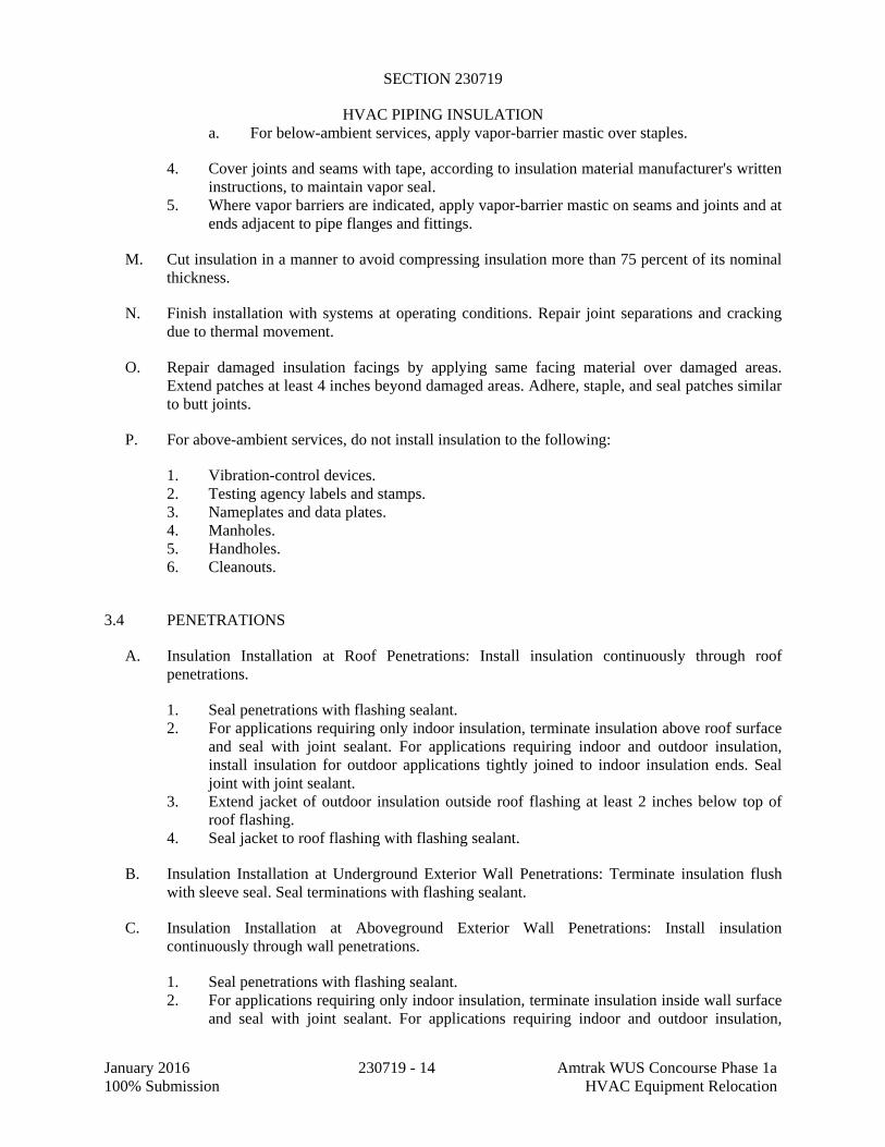
SECTION 230719
HVAC PIPING INSULATION
January 2016 230719 - 14 Amtrak WUS Concourse Phase 1a 100% Submission HVAC Equipment Relocation
a. For below-ambient services, apply vapor-barrier mastic over staples.
4. Cover joints and seams with tape, according to insulation material manufacturer's written instructions, to maintain vapor seal.
5. Where vapor barriers are indicated, apply vapor-barrier mastic on seams and joints and at ends adjacent to pipe flanges and fittings.
M. Cut insulation in a manner to avoid compressing insulation more than 75 percent of its nominal thickness.
N. Finish installation with systems at operating conditions. Repair joint separations and cracking due to thermal movement.
O. Repair damaged insulation facings by applying same facing material over damaged areas. Extend patches at least 4 inches beyond damaged areas. Adhere, staple, and seal patches similar to butt joints.
P. For above-ambient services, do not install insulation to the following:
1. Vibration-control devices. 2. Testing agency labels and stamps. 3. Nameplates and data plates. 4. Manholes. 5. Handholes. 6. Cleanouts.
3.4 PENETRATIONS
A. Insulation Installation at Roof Penetrations: Install insulation continuously through roof penetrations.
1. Seal penetrations with flashing sealant. 2. For applications requiring only indoor insulation, terminate insulation above roof surface
and seal with joint sealant. For applications requiring indoor and outdoor insulation, install insulation for outdoor applications tightly joined to indoor insulation ends. Seal joint with joint sealant.
3. Extend jacket of outdoor insulation outside roof flashing at least 2 inches below top of roof flashing.
4. Seal jacket to roof flashing with flashing sealant.
B. Insulation Installation at Underground Exterior Wall Penetrations: Terminate insulation flush with sleeve seal. Seal terminations with flashing sealant.
C. Insulation Installation at Aboveground Exterior Wall Penetrations: Install insulation continuously through wall penetrations.
1. Seal penetrations with flashing sealant. 2. For applications requiring only indoor insulation, terminate insulation inside wall surface
and seal with joint sealant. For applications requiring indoor and outdoor insulation,

SECTION 230719
HVAC PIPING INSULATION
January 2016 230719 - 15 Amtrak WUS Concourse Phase 1a 100% Submission HVAC Equipment Relocation
install insulation for outdoor applications tightly joined to indoor insulation ends. Seal joint with joint sealant.
3. Extend jacket of outdoor insulation outside wall flashing and overlap wall flashing at least 2 inches.
4. Seal jacket to wall flashing with flashing sealant.
D. Insulation Installation at Interior Wall and Partition Penetrations (That Are Not Fire Rated): Install insulation continuously through walls and partitions.
E. Insulation Installation at Fire-Rated Wall and Partition Penetrations: Install insulation continuously through penetrations of fire-rated walls and partitions.
1. Comply with requirements in Section 078413 "Penetration Firestopping" for firestopping and fire-resistive joint sealers.
F. Insulation Installation at Floor Penetrations:
1. Pipe: Install insulation continuously through floor penetrations. 2. Seal penetrations through fire-rated assemblies. Comply with requirements in
Section 078413 "Penetration Firestopping."
3.5 GENERAL PIPE INSULATION INSTALLATION
A. Requirements in this article generally apply to all insulation materials except where more specific requirements are specified in various pipe insulation material installation articles.
B. Insulation Installation on Fittings, Valves, Strainers, Flanges, and Unions:
1. Install insulation over fittings, valves, strainers, flanges, unions, and other specialties with continuous thermal and vapor-retarder integrity unless otherwise indicated.
2. Insulate pipe elbows using preformed fitting insulation or mitered fittings made from same material and density as adjacent pipe insulation. Each piece shall be butted tightly against adjoining piece and bonded with adhesive. Fill joints, seams, voids, and irregular surfaces with insulating cement finished to a smooth, hard, and uniform contour that is uniform with adjoining pipe insulation.
3. Insulate tee fittings with preformed fitting insulation or sectional pipe insulation of same material and thickness as used for adjacent pipe. Cut sectional pipe insulation to fit. Butt each section closely to the next and hold in place with tie wire. Bond pieces with adhesive.
4. Insulate valves using preformed fitting insulation or sectional pipe insulation of same material, density, and thickness as used for adjacent pipe. Overlap adjoining pipe insulation by not less than two times the thickness of pipe insulation, or one pipe diameter, whichever is thicker. For valves, insulate up to and including the bonnets, valve stuffing-box studs, bolts, and nuts. Fill joints, seams, and irregular surfaces with insulating cement.
5. Insulate strainers using preformed fitting insulation or sectional pipe insulation of same material, density, and thickness as used for adjacent pipe. Overlap adjoining pipe insulation by not less than two times the thickness of pipe insulation, or one pipe diameter, whichever is thicker. Fill joints, seams, and irregular surfaces with insulating

SECTION 230719
HVAC PIPING INSULATION
January 2016 230719 - 16 Amtrak WUS Concourse Phase 1a 100% Submission HVAC Equipment Relocation
cement. Insulate strainers so strainer basket flange or plug can be easily removed and replaced without damaging the insulation and jacket. Provide a removable reusable insulation cover. For below-ambient services, provide a design that maintains vapor barrier.
6. Insulate flanges and unions using a section of oversized preformed pipe insulation. Overlap adjoining pipe insulation by not less than two times the thickness of pipe insulation, or one pipe diameter, whichever is thicker.
7. Cover segmented insulated surfaces with a layer of finishing cement and coat with a mastic. Install vapor-barrier mastic for below-ambient services and a breather mastic for above-ambient services. Reinforce the mastic with fabric-reinforcing mesh. Trowel the mastic to a smooth and well-shaped contour.
8. Stencil or label the outside insulation jacket of each union with the word "union." Match size and color of pipe labels.
C. Insulate instrument connections for thermometers, pressure gages, pressure temperature taps, test connections, flow meters, sensors, switches, and transmitters on insulated pipes. Shape insulation at these connections by tapering it to and around the connection with insulating cement and finish with finishing cement, mastic, and flashing sealant.
D. Install removable insulation covers at locations indicated. Installation shall conform to the following:
1. Make removable flange and union insulation from sectional pipe insulation of same thickness as that on adjoining pipe. Install same insulation jacket as adjoining pipe insulation.
2. When flange and union covers are made from sectional pipe insulation, extend insulation from flanges or union long at least two times the insulation thickness over adjacent pipe insulation on each side of flange or union. Secure flange cover in place with stainless-steel or aluminum bands. Select band material compatible with insulation and jacket.
3. Construct removable valve insulation covers in same manner as for flanges, except divide the two-part section on the vertical center line of valve body.
4. When covers are made from block insulation, make two halves, each consisting of mitered blocks wired to stainless-steel fabric. Secure this wire frame, with its attached insulation, to flanges with tie wire. Extend insulation at least 2 inches over adjacent pipe insulation on each side of valve. Fill space between flange or union cover and pipe insulation with insulating cement. Finish cover assembly with insulating cement applied in two coats. After first coat is dry, apply and trowel second coat to a smooth finish.
5. Unless a PVC jacket is indicated in field-applied jacket schedules, finish exposed surfaces with a metal jacket.
3.6 INSTALLATION OF CALCIUM SILICATE INSULATION
A. Insulation Installation on Straight Pipes and Tubes:
1. Secure single-layer insulation with stainless-steel bands at 12-inch intervals and tighten bands without deforming insulation materials.
2. Install two-layer insulation with joints tightly butted and staggered at least 3 inches. Secure inner layer with wire spaced at 12-inch intervals. Secure outer layer with stainless-steel bands at 12-inch intervals.

SECTION 230719
HVAC PIPING INSULATION
January 2016 230719 - 17 Amtrak WUS Concourse Phase 1a 100% Submission HVAC Equipment Relocation
3. Apply a skim coat of mineral-fiber, hydraulic-setting cement to insulation surface. When cement is dry, apply flood coat of lagging adhesive and press on one layer of glass cloth or tape. Overlap edges at least 1 inch. Apply finish coat of lagging adhesive over glass cloth or tape. Thin finish coat to achieve smooth, uniform finish.
B. Insulation Installation on Pipe Flanges:
1. Install preformed pipe insulation to outer diameter of pipe flange. 2. Make width of insulation section same as overall width of flange and bolts, plus twice the
thickness of pipe insulation. 3. Fill voids between inner circumference of flange insulation and outer circumference of
adjacent straight pipe segments with cut sections of block insulation of same material and thickness as pipe insulation.
4. Finish flange insulation same as pipe insulation.
C. Insulation Installation on Pipe Fittings and Elbows:
1. Install preformed sections of same material as straight segments of pipe insulation when available. Secure according to manufacturer's written instructions.
2. When preformed insulation sections of insulation are not available, install mitered sections of calcium silicate insulation. Secure insulation materials with wire or bands.
3. Finish fittings insulation same as pipe insulation.
D. Insulation Installation on Valves and Pipe Specialties:
1. Install mitered segments of calcium silicate insulation to valve body. Arrange insulation to permit access to packing and to allow valve operation without disturbing insulation.
2. Install insulation to flanges as specified for flange insulation application. 3. Finish valve and specialty insulation same as pipe insulation.
3.7 INSTALLATION OF CELLULAR-GLASS INSULATION
A. Insulation Installation on Straight Pipes and Tubes:
1. Secure each layer of insulation to pipe with wire or bands and tighten bands without deforming insulation materials.
2. Where vapor barriers are indicated, seal longitudinal seams, end joints, and protrusions with vapor-barrier mastic and joint sealant.
3. For insulation with factory-applied jackets on above-ambient services, secure laps with outward-clinched staples at 6 inches o.c.
4. For insulation with factory-applied jackets on below-ambient services, do not staple longitudinal tabs. Instead, secure tabs with additional adhesive as recommended by insulation material manufacturer and seal with vapor-barrier mastic and flashing sealant.
B. Insulation Installation on Pipe Flanges:
1. Install preformed pipe insulation to outer diameter of pipe flange. 2. Make width of insulation section same as overall width of flange and bolts, plus twice the
thickness of pipe insulation.

SECTION 230719
HVAC PIPING INSULATION
January 2016 230719 - 18 Amtrak WUS Concourse Phase 1a 100% Submission HVAC Equipment Relocation
3. Fill voids between inner circumference of flange insulation and outer circumference of adjacent straight pipe segments with cut sections of cellular-glass block insulation of same thickness as pipe insulation.
4. Install jacket material with manufacturer's recommended adhesive, overlap seams at least 1 inch, and seal joints with flashing sealant.
C. Insulation Installation on Pipe Fittings and Elbows:
1. Install preformed sections of same material as straight segments of pipe insulation when available. Secure according to manufacturer's written instructions.
2. When preformed sections of insulation are not available, install mitered sections of cellular-glass insulation. Secure insulation materials with wire or bands.
D. Insulation Installation on Valves and Pipe Specialties:
1. Install preformed sections of cellular-glass insulation to valve body. 2. Arrange insulation to permit access to packing and to allow valve operation without
disturbing insulation. 3. Install insulation to flanges as specified for flange insulation application.
3.8 INSTALLATION OF MINERAL-FIBER INSULATION
A. Insulation Installation on Straight Pipes and Tubes:
1. Secure each layer of preformed pipe insulation to pipe with wire or bands and tighten bands without deforming insulation materials.
2. Where vapor barriers are indicated, seal longitudinal seams, end joints, and protrusions with vapor-barrier mastic and joint sealant.
3. For insulation with factory-applied jackets on above-ambient surfaces, secure laps with outward-clinched staples at 6 inches o.c.
4. For insulation with factory-applied jackets on below-ambient surfaces, do not staple longitudinal tabs. Instead, secure tabs with additional adhesive as recommended by insulation material manufacturer and seal with vapor-barrier mastic and flashing sealant.
B. Insulation Installation on Pipe Flanges:
1. Install preformed pipe insulation to outer diameter of pipe flange. 2. Make width of insulation section same as overall width of flange and bolts, plus twice the
thickness of pipe insulation. 3. Fill voids between inner circumference of flange insulation and outer circumference of
adjacent straight pipe segments with mineral-fiber blanket insulation. 4. Install jacket material with manufacturer's recommended adhesive, overlap seams at least
1 inch, and seal joints with flashing sealant.
C. Insulation Installation on Pipe Fittings and Elbows:
1. Install preformed sections of same material as straight segments of pipe insulation when available.

SECTION 230719
HVAC PIPING INSULATION
January 2016 230719 - 19 Amtrak WUS Concourse Phase 1a 100% Submission HVAC Equipment Relocation
2. When preformed insulation elbows and fittings are not available, install mitered sections of pipe insulation, to a thickness equal to adjoining pipe insulation. Secure insulation materials with wire or bands.
D. Insulation Installation on Valves and Pipe Specialties:
1. Install preformed sections of same material as straight segments of pipe insulation when available.
2. When preformed sections are not available, install mitered sections of pipe insulation to valve body.
3. Arrange insulation to permit access to packing and to allow valve operation without disturbing insulation.
4. Install insulation to flanges as specified for flange insulation application.
3.9 FIELD-APPLIED JACKET INSTALLATION
A. Where metal jackets are indicated, install with 2-inch overlap at longitudinal seams and end joints. Overlap longitudinal seams arranged to shed water. Seal end joints with weatherproof sealant recommended by insulation manufacturer. Secure jacket with stainless-steel bands 12 inches o.c. and at end joints.
3.10 FINISHES
A. Pipe Insulation with ASJ, Glass-Cloth, or Other Paintable Jacket Material: Paint jacket with paint system identified below and as specified in Section 099113 "Exterior Painting" and Section 099123 "Interior Painting."
1. Flat Acrylic Finish: Two finish coats over a primer that is compatible with jacket material and finish coat paint. Add fungicidal agent to render fabric mildew proof.
a. Finish Coat Material: Interior, flat, latex-emulsion size.
B. Color: Final color as selected by Architect. Vary first and second coats to allow visual inspection of the completed Work.
C. Do not field paint aluminum or stainless-steel jackets.
3.11 PIPING INSULATION SCHEDULE, GENERAL
A. Acceptable preformed pipe and tubular insulation materials and thicknesses are identified for each piping system and pipe size range. If more than one material is listed for a piping system, selection from materials listed is Contractor's option.
B. Items Not Insulated: Unless otherwise indicated, do not install insulation on the following:
1. Steam condensate piping between flash tank and steam condensate receiver.

SECTION 230719
HVAC PIPING INSULATION
January 2016 230719 - 20 Amtrak WUS Concourse Phase 1a 100% Submission HVAC Equipment Relocation
3.12 INDOOR PIPING INSULATION SCHEDULE
A. Thickness shall be as follows:
Minimum Pipe Insulation Thickness a ASHRAE Standard 90.1-2010
Fluid Design Operating Temp
Range (oF)
Insulation Conductivity Nominal Pipe or Tube Size (in.)
Conductivity Btu-in./(h ft2
oF)
Mean Rating Temp oF
<1 1 to <1-1/2 1-1/2 to <4 4 to <8 >8
Heating Systems (Steam, Steam Condensate, & Hot Water) b
>350 0.32-0.34 250 4.5 5.0 5.0 5.0 5.0
251-350 0.29-0.32 200 3.0 4.0 4.5 4.5 4.5
201-250 0.27-0.30 150 2.5 2.5 2.5 3.0 3.0
141-200 0.25-0.29 125 1.5 1.5 2.0 2.0 2.0
105-140 0.22-0.28 100 1.0 1.0 1.5 1.5 1.5
Cooling Systems (Chilled Water)
40-60 0.22-0.28 100 0.5 0.5 1.0 1.0 1.0
<40 0.22-0.28 100 0.5 1.0 1.0 1.0 1.5 a For insulation outside the stated conductivity range, the minimum thickness (T) shall be as follows: T=r {(1 +t/r)K/k – 1} where T = minimum insulation thickness (in.), r = actual outside radius of pipe (in.), t = insulation thickness listed in this table for applicable fluid temperature (Btu in.[h ft2 oF]); and k = the upper value of the conductivity range listed in this table for the applicable fluid temperature.
b Piping insulation is not required between the control valve and coil on run-outs when the control valve is located within 4 feet of the coil and the pipe size is 1 in. or less.
B. Any deviation from the specified insulation conductivity, the contractor shall submit calculations showing required insulation thickness for approval. It will be contractor’s responsibility to coordinate increase in insulation thickness with all trades.

SECTION 230719
HVAC PIPING INSULATION
January 2016 230719 - 21 Amtrak WUS Concourse Phase 1a 100% Submission HVAC Equipment Relocation
C. Chilled Water and Brine, above 40 Deg F :
1. Insulation shall be one of the following: a. Cellular glass b. Mineral-Fiber, Preformed Pipe, Type I.
D. Heating-Hot-Water Supply and Return, 200 Deg F and Below:
1. Insulation shall be one of the following:
a. Cellular Glass b. Mineral-Fiber, Preformed Pipe, Type I
E. Steam and Steam Condensate, 350 Deg F and Below:
1. Insulation shall be one of the following:
a. Calcium Silicate. b. Cellular Glass c. Mineral-Fiber, Preformed Pipe, Type I or II
F. Steam and Steam Condensate, above 350 Deg F :
1. Insulation shall be one of the following:
a. Calcium Silicate b. Cellular Glass c. Mineral-Fiber, Preformed Pipe, Type I or II
3.13 OUTDOOR, ABOVEGROUND PIPING INSULATION SCHEDULE
A. The minimum insulation thickness shall be one size larger than the thickness specified for the Indoor Piping insulation.
B. Chilled Water:
1. All Pipe Sizes: Insulation shall be one of the following:
a. Cellular Glass b. Mineral-Fiber, Preformed Pipe Insulation, Type I
C. Heating-Hot-Water Supply and Return, 200 Deg F and Below:
1. All Pipe Sizes: Insulation shall be one of the following:
a. Cellular Glass b. Mineral-Fiber, Preformed Pipe Insulation, Type I

SECTION 230719
HVAC PIPING INSULATION
January 2016 230719 - 22 Amtrak WUS Concourse Phase 1a 100% Submission HVAC Equipment Relocation
D. Steam and Steam Condensate, 350 Deg F and Below:
1. All Pipe Sizes: Insulation shall be one of the following:
a. Calcium Silicate: 4 inches thick b. Mineral-Fiber, Preformed Pipe Insulation, Type I or II
E. Steam and Steam Condensate, above 350 Deg F :
1. All Pipe Sizes: Insulation shall be one of the following:
a. Calcium Silicate b. Mineral-Fiber, Preformed Pipe Insulation, Type I or II
3.14 OUTDOOR, FIELD-APPLIED JACKET SCHEDULE
A. Install jacket over insulation material. For insulation with factory-applied jacket, install the field-applied jacket over the factory-applied jacket.
B. If more than one material is listed, selection from materials listed is Contractor's option.
C. Piping, Exposed: 1. Aluminum, Stucco Embossed with Z-Shaped Locking Seam: 0.032 inch thick. 2. Self-Adhesive Outdoor Jacket, 60-mil thick, laminated vapor barrier and waterproofing
membrane for installation over insulation.
END OF SECTION

SECTION 230800
COMMISSIONING OF HVAC
January 2016 230800 - 1 Amtrak WUS Concourse Phase 1a 100% Submission HVAC Equipment Relocation
PART 1 - GENERAL
1.1 RELATED DOCUMENTS
A. Drawings and general provisions of the Contract, including General Requirements Division 01, Division 23 Specification Sections, and Common Work Requirements for HVAC apply to the work specified in this Section.
1.2 SUMMARY
A. Section includes commissioning process requirements for HVAC&R and associated controls systems, assemblies, and equipment.
B. Related Sections:
1. Division 01 Section "General Commissioning Requirements" for general commissioning process requirements as well as the Commissioning Plan, found as an Appendix to that Specification.
1.3 DEFINITIONS
A. Commissioning Plan: A document that outlines the organization, schedule, allocation of resources, and documentation requirements of the commissioning process.
B. CxA: Commissioning Authority.
C. EOR: Engineer of Record
D. HVAC&R: Heating, Ventilating, Air Conditioning, and Refrigeration.
E. Systems, Subsystems, Equipment, and Components: Where these terms are used together or separately, they shall mean "as-built" systems, subsystems, equipment, and components.
1.4 ALLOWANCES
A. Labor, instrumentation, tools, and equipment costs for technicians for the performance of commissioning testing are covered by the "Schedule of Allowances" Article in Division 01 Section "Allowances."
1.5 UNIT PRICES
A. Commissioning testing allowance may be adjusted up or down by the "List of Unit Prices" Article in Division 01 Section "Unit Prices" when actual man-hours are computed at the end of commissioning testing.

SECTION 230800
COMMISSIONING OF HVAC
January 2016 230800 - 2 Amtrak WUS Concourse Phase 1a 100% Submission HVAC Equipment Relocation
1.6 CONTRACTOR'S RESPONSIBILITIES
A. Perform commissioning tests at the direction of the CxA.
B. Document equipment installation and startup activities as defined by the manufacturer and provide such documentation to the CxA prior to the start of commissioning tests.
C. Attend Commissioning Meetings during construction as designated by the CxA
D. Attend construction phase controls coordination meeting.
E. Attend testing, adjusting, and balancing review and coordination meeting.
F. Participate in HVAC&R systems, assemblies, equipment, and component maintenance orientation and inspection as called out in the installation specifications. 1. Provide the CxA with sample training curricula for review and approval a minimum of
four (4) weeks prior to the scheduled training. 2. Provide EOR and CxA copies of O&M Manuals for review a minimum of four weeks
prior to submission for substantial completion.
G. Provide information requested by the CxA for final commissioning documentation.
H. Provide measuring instruments and logging devices to record test data, and provide data acquisition equipment to record data for the complete range of testing for the required test period.
I. Provide site and equipment specific operating manuals detailing all manufacturer recommended maintenance procedures, spares lists,
1.7 CxA'S RESPONSIBILITIES
A. Provide Project-specific commissioning checklists and commissioning process test procedures for actual HVAC&R systems, assemblies, equipment, and components to be furnished and installed as part of the construction contract.
B. Develop and coordinate the Commissioning Plan.
C. Schedule and conduct Commissioning Meetings during construction as necessary to coordinate commissioning activities within the project delivery team.
D. Direct commissioning testing.
E. Verify testing, adjusting, and balancing of Work are complete.
F. Provide test data, inspection reports, and certificates in Systems Manual.
1.8 COMMISSIONING DOCUMENTATION
A. Provide the following information to the CxA for inclusion in the commissioning plan:

SECTION 230800
COMMISSIONING OF HVAC
January 2016 230800 - 3 Amtrak WUS Concourse Phase 1a 100% Submission HVAC Equipment Relocation
1. Plan for delivery and review of submittals, systems manuals, and other documents and reports.
2. Identification of installed systems, assemblies, equipment, and components including design changes that occurred during the construction phase.
3. Process and schedule for completing construction checklists and manufacturer's prestart and startup checklists for HVAC&R systems, assemblies, equipment, and components to be verified and tested.
4. Certificate of completion certifying that installation, prestart checks, and startup procedures have been completed.
5. Certificate of readiness certifying that HVAC&R systems, subsystems, equipment, and associated controls are ready for testing.
6. Test and inspection reports and certificates. 7. Corrective action documents. 8. Verification of testing, adjusting, and balancing reports.
1.9 SUBMITTALS
A. Certificates of readiness.
B. Certificates of calibration for all test equipment used
C. Certificates of completion and completed checklists for installation, prestart, and startup activities for each piece of commissioned equipment prior to the start of commissioning testing activities.
D. Marked up “As-Built” documentation showing locations valve numbers, connection points, and sizes of installed equipment, piping, ductwork and other ancillary equipment.
E. Operations and Maintenance Manuals
F. Training information, including all curricula, manuals, visual aides and trainer qualifications for each piece of equipment so called out in the installation specifications. Information shall be submitted for approval to the CxA a no later than three (3) weeks prior to proposed training.
PART 2 - PRODUCTS (Not Used)
PART 3 - EXECUTION
3.1 TESTING PREPARATION
A. Certify that HVAC&R systems, subsystems, and equipment have been installed, calibrated, and started and are operating according to the Contract Documents.
B. Certify that HVAC&R instrumentation and control systems have been completed and calibrated, that they are operating according to the Contract Documents, and that pretest set points have been recorded.

SECTION 230800
COMMISSIONING OF HVAC
January 2016 230800 - 4 Amtrak WUS Concourse Phase 1a 100% Submission HVAC Equipment Relocation
C. Certify that testing, adjusting, and balancing procedures have been completed and that testing, adjusting, and balancing reports have been submitted, discrepancies corrected, and corrective work approved.
D. Set systems, subsystems, and equipment into operating mode to be tested (e.g., normal shutdown, normal auto position, normal manual position, unoccupied cycle, emergency power, and alarm conditions).
E. Inspect and verify the position of each device and interlock identified on checklists.
F. Check safety cutouts, alarms, and interlocks with smoke control and life-safety systems during each mode of operation.
G. Testing Instrumentation: Install measuring instruments and logging devices to record test data as directed by the CxA.
3.2 Testing AND BALANCING VERIFICATION
A. Prior to performance of testing and balancing Work, provide copies of reports, sample forms, checklists, and certificates to the CxA.
B. Notify the CxA at least 10 days in advance of testing and balancing Work, and provide access for the CxA to witness testing and balancing Work.
C. Provide technicians, instrumentation, and tools to verify testing and balancing of HVAC&R systems at the direction of the CxA.
1. The CxA will notify testing and balancing Subcontractor 10 days in advance of the date of field verification. Notice will not include data points to be verified.
2. The testing and balancing Subcontractor shall use the same instruments (by model and serial number) that were used when original data were collected.
3. Failure of an item includes, other than sound, a deviation of more than 10 percent. Failure of more than 10 percent of selected items shall result in rejection of final testing, adjusting, and balancing report. For sound pressure readings, a deviation of 3 dB shall result in rejection of final testing. Variations in background noise must be considered.
4. Remedy the deficiency and notify the CxA so verification of failed portions can be performed.
3.3 GENERAL TESTING REQUIREMENTS
A. Provide technicians, instrumentation, and tools to perform commissioning test at the direction of the CxA.
B. Scope of HVAC&R testing shall include entire HVAC&R installation, from central equipment for heat generation and refrigeration through distribution systems to each conditioned space. Testing shall include measuring capacities and effectiveness of operational and control functions.

SECTION 230800
COMMISSIONING OF HVAC
January 2016 230800 - 5 Amtrak WUS Concourse Phase 1a 100% Submission HVAC Equipment Relocation
C. Test all operating modes, interlocks, control responses, and responses to abnormal or emergency conditions, and verify proper response of building automation system controllers and sensors.
D. The CxA along with the HVAC&R Subcontractor, testing and balancing Subcontractor, and HVAC&R Instrumentation and Control Subcontractor shall prepare detailed testing plans, procedures, and checklists for HVAC&R systems, subsystems, and equipment.
E. Tests will be performed using design conditions whenever possible.
F. Simulated conditions may need to be imposed using an artificial load when it is not practical to test under design conditions. Before simulating conditions, calibrate testing instruments. Provide equipment to simulate loads. Set simulated conditions as directed by the CxA and document simulated conditions and methods of simulation. After tests, return settings to normal operating conditions.
G. Where ever possible, actual conditions will be created to test sequences of operations. The CxA may direct that set points be altered for simulation when creating actual conditions is not practical.
H. The CxA may direct that sensor values be altered with a signal generator when design or simulating conditions and altering set points are not practical.
I. If tests cannot be completed because of a deficiency outside the scope of the HVAC&R system, document the deficiency and report it to the Owner. After deficiencies are resolved, reschedule tests.
J. If the testing plan indicates specific seasonal testing, complete appropriate initial performance tests and documentation and schedule seasonal tests.
3.4 HVAC&R SYSTEMS, SUBSYSTEMS, AND EQUIPMENT TESTING PROCEDURES
A. HVAC&R Instrumentation and Control System Testing: Field testing plans and testing requirements are specified in Division 23 Sections "Instrumentation and Control for HVAC" and "Sequence of Operations for HVAC Controls." Assist the CxA with preparation of testing plans.
B. Pipe system cleaning, flushing, hydrostatic tests, and chemical treatment requirements are specified in Division 23 piping Sections. HVAC&R Subcontractor shall prepare a pipe system cleaning, flushing, and hydrostatic testing plan. Provide cleaning, flushing, testing, and treating plan and final reports to the CxA. Plan shall include the following:
1. Sequence of testing and testing procedures for each section of pipe to be tested, identified by pipe zone or sector identification marker. Markers shall be keyed to Drawings for each pipe sector, showing the physical location of each designated pipe test section. Drawings keyed to pipe zones or sectors shall be formatted to allow each section of piping to be physically located and identified when referred to in pipe system cleaning, flushing, hydrostatic testing, and chemical treatment plan.
2. Description of equipment for flushing operations.

SECTION 230800
COMMISSIONING OF HVAC
January 2016 230800 - 6 Amtrak WUS Concourse Phase 1a 100% Submission HVAC Equipment Relocation
3. Minimum flushing water velocity. 4. Tracking checklist for managing and ensuring that all pipe sections have been cleaned,
flushed, hydrostatically tested, and chemically treated. 5. The plan shall be provided to the CxA for review a minimum of one (1) week prior to
scheduled cleaning and flushing activities. Plan shall be approved prior to the commencement of such activity.
6. The contractor shall confirm in writing the date and time of the start of flushing activity to the CxA 48 hours prior start.
C. HVAC&R Distribution System Testing: Provide technicians, instrumentation, tools, and equipment to test performance of air distribution, steam, and hydronic distribution systems.
END OF SECTION

SECTION 230900
INSTRUMENTATION AND CONTROL FOR HVAC
January 2016 230900 - 1 Amtrak WUS Concourse Phase 1a100% Submission HVAC Equipment Relocation
PART 1 - GENERAL
1.1 SUMMARY
A. The Contractor shall provide and install a system which shall provide direct digital control for the Heating, Ventilating and Air Conditioning, (HVAC) systems, including interfacing with the building’s existing control system which is TAC I/NET SEVEN, as shown on the drawings and as specified. The Contractor shall furnish and install the necessary hardware, wiring, computing equipment and software as defined in this specification and as required to cause these systems to operate in accordance with the specified Sequence of Operation.
B. The Building Automation System (BAS) shall have a native BACnet architecture and be fully BACnet compliant.
1.2 DEFINITIONS
A. 10 Base T: The technical name for twisted pair Ethernet
B. Backbone: The high traffic density connectivity portion of the communication network.
C. BACnet: The Building Automation and Control networking communication protocol ANSI/ASHRAE, Standard 135-1995, developed by ASHRAE to provide a universal means by which building automation devices from various manufacturers can share data and work together.
D. BAS: Building Automation System (used interchangeably with BMS – Building Management System.)
E. BIBBS: BACNET Interoperability Building Blocks
F. BMS – Building Management System (used interchangeably with BAS: Building Automation System.)
G. Bridge: A device that connects two or more LAN segments at the physical and data link layers. This device may also perform message filtering if programmed to do so.
H. Browser: A computer program that accesses and displays information from the Internet or intranet.
I. Category 5 cable: A type of wiring used for twisted pair Ethernet. The electrical characteristics of Cat 5 wiring make it less susceptible to electrical interference than lower categories.
J. Client: A system or device that makes use of another device for some particular purpose through a system request.

SECTION 230900
INSTRUMENTATION AND CONTROL FOR HVAC
January 2016 230900 - 2 Amtrak WUS Concourse Phase 1a100% Submission HVAC Equipment Relocation
K. Conformance Classes: The set of requirements to be met in order for a device to conform to BACnet. BACnet defines six (6) levels of required support for standard objects and services. The higher the Conformance Class, the greater number of services provided.
L. Control Devices: Valves, dampers, variable frequency drives, and other appurtenances that change the properties and henceforth vary the conditions of the controlled parameter, such as temperature, air flow, pressure, etc.
M. Controlled Parameter: Air, water, glycol, steam or other media whose conditions are maintained or varied by the automatic control system and the control devices.
N. Data Link Layer: Part of the Protocol Stack. The layer resides between the Physical Layer and the Network Layer. It passes to the Network Layer only acceptable incoming BACnet messages received from the Physical Layer. The Data Link Layer is responsible for adding a code to outgoing messages to identify them as BACnet messages before passing them on to the Physical Layer.
O. DDC: Direct digital control.
P. DDE: Dynamic Data Exchange.
Q. Device (BACnet): A device, real or virtual, that supports digital communication using the BACnet protocol. Examples would be an operator terminal, router, unitary controller, etc.
R. Ethernet: Ethernet is a widely used Local Area Network (LAN). Ethernet, which conforms to IEEE Standard 802.3.
S. Events: Changes in the state of an object, typically between Normal, Off-Normal, and Fault Condition. Events may be reported to other BACnet devices.
T. Fiber: An abbreviation for optical fiber.
U. Firewall: A security mechanism placed at the connection between networks and/or at networks outside connections. The firewall restricts access to the network.
V. Gateway: A device that connects two or more dissimilar networks by message translation and signal conditioning, permitting information exchange among them. A gateway would be necessary to translate LonWorks messages to the BACnet form.
W. Gbps: Gigabits per second. A unit of data transfer speed equal to 1024 Mbps.
X. GUI: Graphical User Interface, a type of Operator Interface Device for a BAS.
Y. Half Router: A device or node that can participate as one partner in an RS-232 point-to-point (PTP) connection. The Half Router partners that form an active PTP connection act as a single router for as long as the PTP connection between the two is active.
Z. Hardware address: The address assigned to a computer or DDC controller that attaches to a network. A data frame sent from one hardware device to another hardware device must contain the recipient’s address. A hardware address is also called the physical address.

SECTION 230900
INSTRUMENTATION AND CONTROL FOR HVAC
January 2016 230900 - 3 Amtrak WUS Concourse Phase 1a100% Submission HVAC Equipment Relocation
AA. Hertz: A unit of measure equal to an oscillation per second.
BB. HTML: The source form used for documents on the Internet or on an intranet. HTML embeds commands that determine formatting along with the text to be displayed.
CC. Instance: A number which uniquely identifies an object within a device (e.g., Analog Input No.1, No. 2, etc.). Device Objects are required to have an instance number that is unique to their internetwork. Instance numbers may range from 0 to 4194303.
DD. ID: Identification (name, number, plate, or tag).
EE. I/O: Input/output
FF. I/P: Internet Protocol.
GG. Internetwork: Two or more networks connected by routers (the Internet itself and internetwork), up to 65,535 interconnected networks are allowed by BACnet. A BACnet internetwork provides only one message path between two devices. Internetworks may contain similar or dissimilar physical types, so an internetwork may consist of two ethernet LANs, or an ethernet LAN and several MS/TP LANs, etc.
HH. Intranet: A computer network with restricted access, as within a corporation, that uses software and protocols developed for the Internet.
II. IP: Internet Protocol. The protocol that defines both the format of packets used on a TCP/IP internet or intranet and the mechanism for routing a packet to its destination.
JJ. IP address: A 32-bit address assigned to a device that uses TCP/IP protocols.
KK. Java: A programming language defined by Sun Microsystems for use in Internets.
LL. Kbps: A unit of data transfer equal to 1024 bits per second.
MM. LAN: Local Area Network; A LAN is a network of interconnected hardware devices sharing resources within a relatively small geographic area.
NN. LonTalk: A LAN using a proprietary device called a neuron chip for communication. It can operate over a variety of physical media including twisted pair, power line carrier, and wireless transfers.
OO. LPDU: Link Protocol Data Units are packets created and read by the Data Link Layer. They contain a 3-byte header which identifies the packets as having been created by, and intended to be read by, a BACnet system. The header is followed by the BACnet LPDU.
PP. Mbps: A unit of data transfer equal to 1024 Kbps.
QQ. MS/TP: The Master-Slave/Token-Passing EIA-485 LAN developed for BACnet by ASHRAE. Operates at 9600, 19.2K, 38.4K and 76.8 K BPS. Master nodes (devices) pass around a speaking token which entitles the holder to initiate BACnet messages. Slave nodes can only respond to messages from Masters.

SECTION 230900
INSTRUMENTATION AND CONTROL FOR HVAC
January 2016 230900 - 4 Amtrak WUS Concourse Phase 1a100% Submission HVAC Equipment Relocation
RR. Native BACnet: A Building Automation System that uses the BACnet protocol for its data transfer between hardware devices.
SS. NIST: The National Institute of Standards and Technology is developing a BACnet device-compliance testing facility in Gaithersburg, MD.
TT. NODE: A computer or digital device connected to a network, with an address on that network.
UU. OBJECT (BACnet): BACnet objects represent, in a standardized way, the information required for a building automation control system. The analog input object, for example, represents sensor inputs such as temperature sensors.
VV. Optical Carrier (OC): A set of standards adopted by common carriers for the high speed transmission of digital information over optical fiber.
WW. Optical fiber: Glass fiber used in digital networks.
XX. Optical modem: A modem that uses modulated light waves to provide digital communication.
YY. Object Identifier: A 32-bit number which uniquely identifies an object within a device, or the device object internetwork-wide. 10 bits represent the object type and 22 bits the instance number.
ZZ. Open System Interconnection standards.
AAA. Packet: A small, self-contained parcel of data sent across a digital network.
BBB. PAD (Packet-Assembler-Disassemblers): A device that sends BACnet messages across BACnet incompatible networks. The sending PAD receives the message from a BACnet network, encapsulates it in the correct format, and sends it on the non-compatible network to a receiving PAD. The receiving PAD removes the message from its encapsulation and transmits it on another BACnet network.
CCC. PC: Personal Computer.
DDD. PDA: Personal Digital Assistant
EEE. Peer-to-Peer Communication: Communication between equals. In BACnet, application programs (performing the functions of the BACnet devices on which they run) in devices of the appropriate conformance class talk to each other as peers, using the Protocol Stacks to deliver their message to each other. Likewise, Network Layers may talk as peers to determine how to route messages.
FFF. Physical Segment: A single continuous medium 9-wire to which BACnet nodes are attached.
GGG. PICS (Protocol Implementation Conformance Statement): A written document identifying the particular BACnet objects and services and other capabilities that are implemented in the device (see also Section 1.3.C, “Conformance Classes”).
HHH. PID: Proportional Integral and Derivative.

SECTION 230900
INSTRUMENTATION AND CONTROL FOR HVAC
January 2016 230900 - 5 Amtrak WUS Concourse Phase 1a100% Submission HVAC Equipment Relocation
III. Property: A particular characteristic of a BACnet object. Examples of properties are Description (a text description of what the object represents, such as OSA for outside air, and analog input object), Present Value (22 for the same input) and engineering units (degrees Celsius).
JJJ. Protocol: A design that specifies the details of how digital devices interact.
KKK. Protocol Address: A number assigned to a digital device that is used as the destination address in packets sent to that device.
LLL. Protocol Stack: The four layers through which BACnet messages pass when sent to or from a BACnet device. The Protocol stack provides data encoding, packetizing, sequencing, segmenting, routing and communication services.
MMM. PTP: The Point-To-Point protocol provides serial communications between two BACnet half-router devices, typically for dial-up communications over-the-phone modems. It may be also applied as a hard-wired interface. For the duration of the connections, messages may be passed between networks on either side of the PTP connections.
NNN. Repeater: A device that connects two or more physical segments of a LAN at the physical layer and exactly reproduces the electrical signals on either side so that nodes on either side of the repeater are considered to be on the same network.
OOO. Router: A device which connects two or more networks, of same or different types, so that a BACnet message may be transferred across the appropriate networks to reach its destination.
PPP. RS-232-C: The technical name of the standard for serial data connections such as those between a computer and a keyboard.
QQQ. RTD: Resistance temperature detector.
RRR. Server: A computer or hardware device which stores the resources accessed by other computers or hardware devices (clients).
SSS. Services (BACnet): BACnet defines 26 standard services; some services read or write properties of objects in the receiving device, others convey notification of alarms or other special events, others read and write files, and so on.
TTT. SNMP: Simple Network Management Protocol. The protocol that specifies how a network management station communicates with agent software in remote devices such as routers. SNMP defines the format of messages and their meaning.
UUU. TCP/IP: The protocol suite used in the Internet. Although the suite contains many protocols, TCP and IP are two of the most important.
VVV. Thinnet: A term used for the version of Ethernet that uses thinner coaxial cable.
WWW. Thin-client architecture: A term used to describe server/client system architectures in which one or more powerful hardware devices (servers) store the resources accessed by other less powerful hardware devices (clients).

SECTION 230900
INSTRUMENTATION AND CONTROL FOR HVAC
January 2016 230900 - 6 Amtrak WUS Concourse Phase 1a100% Submission HVAC Equipment Relocation
XXX. Token Ring Network: A Token Ring Network is a Local Area Network (LAN) in which each of the computers are connected in a ring or a star topology and a bit, or a token-passing scheme, is used in order to prevent the collision of data between two computers that want to send messages at the same time. The token ring protocol is the second most widely used pattern after the Ethernet. A typical arrangement is as follows:
1. Empty information frames are continuously circulated on the ring;
2. When a computer has a message to send, it inserts a token in an empty frame (this may consist of simply changing a 0 to a 1 in the token bit of the frame) and inserts a message and a destination identifier in the frame;
3. The frame is then examined by each successive workstation. If the workstation sees that it is the destination for the message, it copies the message from the frame and changes the token back to 0. When the frame gets back to the originator, it sees the token has been changed to 0 and the message has been copied and received. It removes the message from the frame. The frame continues to circulate as an empty frame, ready to be taken by workstation when it has a message to send.
YYY. TP Ethernet: Twisted pair Ethernet.
ZZZ. Unitary Controller: Devices which controls and/or monitors a single piece of equipment.
AAAA. WAN: Wide Area Network; a WAN is a network of interconnected hardware devices sharing resources within a larger geographic area than a LAN; may integrate numerous bus networks or LANs and multiple firewalls.
BBBB. WEB: A synonym for the World Wide Web. In modern usage pertains to both the Internet and to intranets using the TCP/IP Protocol.
1.3 SYSTEM DESCRIPTION
A. The system shall consist of a series of digital controllers which under this scope of work shall be connected to the existing control system (level of communication delineated in the sequences of operation) and shall be configured under this scope of work to be able to be connected in the fu-ture to a new BMS head end via a new BMS network without hardware modifications. The con-trollers shall be located adjacent to the equipment they control and shall be sized for the current and future tasks assigned to them (as called out in the sequences of operation). The system shall utilize distributed processing architecture, with one controller to be provided for each major piece of equipment controlled.
B. The future communication network shall be BACnet over Ethernet or BACnet over ARCNET.
C. Electrical Work:
1. Provide the BMS power and control wiring required but may not be indicated in the Division 26 drawings, in accordance with Division 26. This shall include power requirements for con-trol panels, field controllers, sensors and other control devices. Provide transformers neces-

SECTION 230900
INSTRUMENTATION AND CONTROL FOR HVAC
January 2016 230900 - 7 Amtrak WUS Concourse Phase 1a100% Submission HVAC Equipment Relocation
sary to step down from the available voltage to the voltage required to operate the control system products and control devices.
D. Other Work:
1. The work included under this Division shall include the drawings, specifications, submittals, equipment, labor, materials, technical supervision, transportation, training services, documen-tation, warranty, and other appurtenant work as required to furnish and install a fully opera-tional system to monitor and control, in strict accordance with these specifications. An appa-ratus, appliance, material or work not shown on the drawings but mentioned in the specifica-tions, or vice versa, or incidental accessories necessary to make the work entirely complete and ready for operation, even if not particularly specified, shall be furnished, delivered and installed by the Contractor without additional expense to the Owner.
E. Completion:
1. It is the intention of the specifications and drawings to call for furnished work, tested, and ready for operation. Wherever the word “provide” is used, it shall mean “provide and install complete and ready for use.”
F. Omissions:
1. Minor details not usually shown or specified but necessary for proper installation and opera-tions shall be included, as if herein specified and/or shown.
G. Contractor’s Esoteric Omissions:
1. The omission of hardware, firmware, and software components required to satisfy the speci-fied configuration(s), but not specified due to the esoteric requirements of a particular manu-facturer’s product design shall not relieve the Contractor from the responsibilities of provid-ing and installing omitted apparatuses, (i.e. feed-back circuits, calibration resistors, and over-ride detection interface devices).
1.4 SUBMITTALS
A. Product Data: Include manufacturer's technical literature for each control device. Indicate dimensions, capacities, performance characteristics, electrical characteristics, finishes for materials, and installation and startup instructions for each type of product indicated.
B. Equipment: Shop drawings from manufacturer, detailing equipment assemblies and indicating dimensions, weights, loadings, required clearances, method of field assembly, components, and location and size of each field connection. Submit damper leakage and flow characteristics, plus size schedule for control dampers and control valves.
C. Shop Drawings: Detail equipment assemblies and indicate dimensions, weights, loads, required clearances, method of field assembly, components, and location and size of each field connection.
1. Bill of materials of equipment indicating quantity, manufacturer, and model number.

SECTION 230900
INSTRUMENTATION AND CONTROL FOR HVAC
January 2016 230900 - 8 Amtrak WUS Concourse Phase 1a100% Submission HVAC Equipment Relocation
2. Schematic flow diagrams showing fans, pumps, coils, dampers, valves, and control devices.
3. Wiring Diagrams: Power, signal, and control wiring. 4. Details of control panel faces, including controls, instruments, and labeling. 5. Written description of sequence of operation. 6. Schedule of dampers including size, leakage, and flow characteristics. 7. Schedule of valves including flow characteristics. 8. DDC System Hardware:
a. Wiring diagrams for control units with termination numbers. 9. Controlled Systems:
a. Schematic diagrams of each controlled system with control points labeled and control elements graphically shown, with wiring.
b. Points list.
D. Wiring Diagrams: Submit wiring diagrams, detailing wiring for power, signal, and control systems and differentiating clearly between manufacturer-installed and field-installed wiring.
E. Data Communications Protocol Certificates: Certify that each proposed DDC system component complies with ASHRAE 135.
F. Software and Firmware Operational Documentation: Include the following:
1. Software operating and upgrade manuals. 2. Program Software Backup: On a magnetic media or compact disc, complete with data
files. 3. Device address list. 4. Printout of software application and graphic screens. 5. Software license required by and installed for DDC control systems.
G. Operation and Maintenance Data: For HVAC instrumentation and control system to include the following:
1. Maintenance instructions and lists of spare parts for each type of control device. 2. Interconnection wiring diagrams with identified and numbered system components and
devices. 3. Keyboard illustrations and step-by-step procedures indexed for each operator function. 4. Inspection period, cleaning methods, cleaning materials recommended, and calibration
tolerances. 5. Calibration records and list of set points.
1.5 QUALITY ASSURANCE
A. Products shall be standard manufacturer products having been in commercial or industrial use for at least one year prior to the bid date for this project. Products shall comply with the following as a minimum:
1. NFPA 90A, “Installation of Air Conditioning and Ventilation Systems.” 2. NISTIR 6392 for DDC system control components. 3. ANSI/ASHRAE Standard 135-1995 for BACnet compatible system control components. 4. Applicable provisions of NFPA code.

SECTION 230900
INSTRUMENTATION AND CONTROL FOR HVAC
January 2016 230900 - 9 Amtrak WUS Concourse Phase 1a100% Submission HVAC Equipment Relocation
5. Applicable provisions of NEC.
B. Each system component, such as digital controllers shall be manufactured under ISO 9001 stand-ards for quality.
C. Contractor shall have been in business installing and maintaining the same brand of equipment as used on this project for at least three (3) years prior to the bid date of this project.
D. Installer Qualifications: Installer shall have at least 5 years experience installing BMS and shall be an experienced installer who is an authorized representative of the BMS manufacturer for both installation and maintenance of products and systems required for this project.
E. Manufacturer Qualifications: A firm experienced in manufacturing products for BMSs the same as or similar to those required for this project and with a record of successful in-service perfor-mance for a minimum of one year prior to the bid date for this project.
F. Electrical Components, Devices, and Accessories: Listed and labeled as defined in NFPA 70, Ar-ticle 100, by a testing agency acceptable to authorities having jurisdiction, and certified and marked for intended use.
1.6 DELIVERY, STORAGE, AND HANDLING
A. Contractor shall receive, store and deliver to the jobsite the materials required for this project.
B. Materials which are to be installed in sheet metal or piping systems, such as valves, wells, pres-sure taps, flow meters, dampers and sensors, shall be delivered directly to the sheet metal or pip-ing contractor for installation.
C. System Software: Update to latest version of software at Project completion.
1.7 COORDINATION
A. Coordinate material delivery to comply with project schedule.
B. Coordinate conduit, and wiring installation with other trades to avoid conflicts.
C. Coordinate panel locations and installation with other trades to avoid conflicts and to provide power and other requirements.
D. Coordinate supply of conditioned electrical branch circuits for control units and operator work-station.
1.8 DEMONSTRATION AND INSPECTION
A. System: The complete Building Automation System shall be demonstrated to the Owner’s repre-sentative to perform as specified, and Owner’s operating personnel shall be instructed in the op-erating procedures until they are familiar with the system

SECTION 230900
INSTRUMENTATION AND CONTROL FOR HVAC
January 2016 230900 - 10 Amtrak WUS Concourse Phase 1a100% Submission HVAC Equipment Relocation
B. Training: Technical classes for instruction of Operation and Maintenance personnel shall be pro-vided for no less than 4 people. The classes shall be developed and administered to provide com-plete, hands-on training in the use and programming of system hardware and software, mainte-nance and operation of transmission systems and each component of this system. Classes shall be provided by professional training personnel employed by the manufacturer. Classes shall be con-ducted on site, with the expenses for travel, lodging, and technical supplies to be provided by the manufacturer. Initial training shall be for a period of 3 days with follow-up training of one day per month for a period of 3 months.
C. Operation: Every BMS component, wiring, and control program installed under this section shall be demonstrated to the Owner’s representative to be in working condition. Once each component operation has been verified and the system has been properly commissioned with the rest of the equipment and building systems, the systems will be ready for final acceptance. At that time, the warranty period will begin and will extend only to the replacement of material with manufactur-er’s defects, and to normal or recommended recalibration or adjustments.
1.9 WARRANTY
A. The system herein specified shall be free from defects in workmanship and material under normal use and service. If within 12 months from the date of acceptance by the Owner/Architect, equip-ment or software herein described is proven to be defective in workmanship or material, it shall be adjusted, repaired, or replaced free of charge. This system warranty shall also include each software program, upgrade and maintenance
PART 2 - PRODUCTS
2.1 GENERAL
A. General: Provide a Building Automation System for the HVAC system equal to the equipment below, including the control accessories and devices necessary to accomplish the desired results, whether specifically mentioned herein or not. The BMS shall employ direct digital control (DDC) technology. Field controllers shall be DDC. The DDC system shall maintain stable tem-perature, pressure, and flow control and other conditions as indicated. The end-to-end accuracy of the system, including intermediate errors and the A/D conversion and display, shall be ± 1-deg F or as specified for the particular sensor point, for temperature, and be ± 3%RH for relative hu-midity.
B. The BMS shall consist of field control panels and controllers. The software control programs shall reside in the local controller for each item of equipment. The alarms shall be sent to the ex-isting control system.
C. Future communications between the field control panels and OIDs and between the field control panels and the terminal unit controllers shall be through the future LAN. The future communica-tions protocols, wiring types, and equipment in this project scope shall be in strict accordance with ASHRAE Standard 135, BACnet.

SECTION 230900
INSTRUMENTATION AND CONTROL FOR HVAC
January 2016 230900 - 11 Amtrak WUS Concourse Phase 1a100% Submission HVAC Equipment Relocation
2.2 MANUFACTURERS
A. Manufacturers: Subject to compliance with requirements, provide products by one of the manufacturers:
1. Delta Controls Inc. 2. Honeywell International Inc.; Home & Building Control. 3. Johnson Controls, Inc.; Controls Group. 4. Reliable Controls. 5. Siemens Building Technologies, Inc. 6. TAC/Schneider Electric.
2.3 EQUIPMENT-LEVEL DIGITAL CONTROLLERS
A. BACnet BIBBs: Controllers shall be BACnet® Testing Laboratory (BTL) listed. General Pur-
pose Digital Controllers shall use BACnet as the native communications protocol between con-trollers.
B. Communication Speed: Controllers shall communicate at a minimum of 150 Kbps using Ethernet or ARCNET implemented over EIA-485, using an unshielded twisted pair at the Data Link Layer.
C. General Specification: Each Digital Controller shall be capable of stand-alone DDC operation utilizing its own 16 or 32-bit processor, non-volatile flash memory, input/output, 10-bit A to D conversion, hardware clock/calendar, and voltage transient and lightning protection devices. Non-volatile flash memory shall have a battery backup of at least five years. Firmware revisions to the controller shall be made from the BMS server or remotely over the intranet or Internet. Controllers shall not require component changes to implement firmware revisions.
D. Self-Test Diagnostics: Each controller shall include self-test diagnostics, enabling the controller to automatically report malfunctions to the server.
E. Each Multiple Application Digital Controller shall contain both software and firmware to perform full DDC Proportional, Integral, and Derivative (PID) control loops and programs.
F. Input/Output Processing:
1. Digital outputs shall be relays, each configured as normally open or normally closed. Each output shall have a manual Hand-Off-Auto switch to allow for override and a LED to indicate the operating mode of the output.
2. Universal inputs shall be Thermistor, RTD 0-10VDC, 0-20 mA, resistive and dry contact. 3. Analog output shall be electronic, voltage mode 0-10 VDC or current mode 4-20mA. 4. Analog pneumatic outputs shall be 0-20 psi. Each pneumatic output shall have a feedback
transducer to be used in the system for software programming needs. The feedback transduc-er shall measure the actual psi output value and not a calculated value. Each output shall have a manual override switch that will allow the output to be configured in one of three ways: open, closed, or automatic operation. A LED shall indicate the state of each output.

SECTION 230900
INSTRUMENTATION AND CONTROL FOR HVAC
January 2016 230900 - 12 Amtrak WUS Concourse Phase 1a100% Submission HVAC Equipment Relocation
2.4 GATEWAYS
A. Bi-Directional Protocol Translator (BPT): The new Building Automation System shall establish a seamless interconnection with the existing control systems and future BMS that will be in-stalled in the future. These systems shall be controlled and monitored as delineated by the se-quences of operation.
B. BPT Specification:
1. The BPT shall be a microprocessor-based communication device to provide seamless, two-way translation between two or more standard or non-standard protocols.
2. The BPT shall be available for a variety of Data Link/Physical Layer configurations, includ-ing PTP (point-to-point) via EIA-232, MS/TP via EIA-485, and ARCNET.
3. In addition to BACnet, the BPT shall also support other protocols including Modbus, JBus and other protocols as specified herein for electrical/mechanical subsystems.
4. The BPT shall have at least three communications ports: One shall be for communication be-tween native BACnet controllers residing on the controller network; the other two ports shall have the ability to be configured for different protocols.
5. The BPT shall provide full custom programmability of the data flowing between the net-works, using the same graphic programming as specified herein. The system shall have the ability to create custom building control strategies using global data between networks.
2.5 PANELS
A. Cabinet: Each DDC Controller shall be enclosed in a field panel or equipment enclosure. The field panel cabinet shall be constructed of 16 US gauge sheet steel. Provide sufficient access for wire and conduit to enter the cabinet. Each of the field control panel locks for the project shall be keyed alike. The cabinet shall be shipped to the project for installation without electronics. The electronics shall be added at the time of wire termination and system commissioning. The control wiring and system communications shall be electrically terminated inside the field panel. Each panel shall include the following:
1. Receptacles: Provide a 20 ampere duplex receptacle inside or immediately adjacent to the field control panel.
2. Master Disconnect Switch: Provide a master electrical power disconnect switch inside the field control panel to disconnect the external power to the cabinet for maintenance and repair. The disconnect switch shall not affect the duplex receptacle hereinbefore specified.
3. Terminal Strips: Provide screw type terminal strips in the field control panel for the termina-tion of field wiring. Lay out terminal strips in a neat and orderly fashion and label each ter-mination. Wiring entering the panel shall be routed through the panel wire-ways in a neat and workmanlike manner, properly tied or laced and terminated.
B. Power Supplies: Transformers with Class 2 current-limiting type or overcurrent protection; limit connected loads to 80 percent of rated capacity. DC power supply shall match output current and voltage requirements and be full-wave rectifier type with the following:
1. Output ripple of 5.0 mV maximum peak to peak. 2. Combined 1 percent line and load regulation with 100-mic.sec. response time for 50
percent load changes.

SECTION 230900
INSTRUMENTATION AND CONTROL FOR HVAC
January 2016 230900 - 13 Amtrak WUS Concourse Phase 1a100% Submission HVAC Equipment Relocation
3. Built-in overvoltage and overcurrent protection and be able to withstand 150 percent overload for at least 3 seconds without failure.
C. Power Line Filtering: Internal or external transient voltage and surge suppression for controllers with the following:
1. Minimum dielectric strength of 1000 V. 2. Maximum response time of 10 nanoseconds. 3. Minimum transverse-mode noise attenuation of 65 dB. 4. Minimum common-mode noise attenuation of 150 dB at 40 to 100 Hz
2.6 TRANSDUCERS
A. Transducers shall convert the output signal from the digital controller into an analog signal ap-propriate to the controlled device, such as a pneumatic damper operator or valve operator. Trans-ducers shall be accurate to within 1% of the signal range. See other sections for the controlled devices, actuators, relays, etc.
2.7 DDC CONTROLLER SOFTWARE
A. The system shall continuously perform DDC functions at the local control module in a stand alone mode. The operator shall be able to design and modify the control loops to meet the re-quirements of the system being operated. The operators shall use system-provided displays for tuning of PID loops. These displays shall include the past three input variable values, the setpoint for the loop, the sample interval and the results of the PID effects on the final output.
B. Each control module shall perform the following functions:
1. Identify and report alarm condition. 2. Execute each application programs indicated in the sequences of operation. 3. Execute DDC algorithms. 4. Trend and store data. 5. Maintain time-of-day schedules.
C. Scheduled Start/Stop Program: Provide software to start and stop equipment based on the time of day and day of week, including holidays. The program shall monitor the controlled equipment status to verify that the start and stop command has been carried out, and provide the system with an alarm when the equipment does not start or stop, fails, or is locally started or stopped, or is manually overridden via the controller HOA switches and/or local motor starter HOA switch. The system shall be capable of the following scheduling features:
1. Scheduling will be by individual air handling unit and fan. Each schedule shall provide be-ginning and ending dates and times (hh:mm). A weekly repeating schedule, i.e. between 8:00 a.m. and 5:00 p.m., Monday through Friday shall constitute one schedule, not five.
2. Leap years and Daylight Savings Time shall be adjusted automatically without operator in-tervention.

SECTION 230900
INSTRUMENTATION AND CONTROL FOR HVAC
January 2016 230900 - 14 Amtrak WUS Concourse Phase 1a100% Submission HVAC Equipment Relocation
D. In the event of a controller failure, the points under its control shall be commanded to the failure mode as indicated on the I/O Summary Table. The DDC software shall reside in the respective control module.
E. Power Failure/Automatic Restart:
1. Power failures shall cause the control module to go into an orderly shutdown with no loss of program memory.
2. Upon resumption of power, the Control module shall automatically restart and printout the time and date of the power failure and restoration at the respective OID.
3. Prior to taking action, the controller shall look at the actual time-of-day and the programmed schedule for the controlled systems. If systems are operating, the restart program shall auto-matically restart affected field equipment. The operator shall be able to define an automatic power up time delay for each piece of equipment under control.
F. Space Temperature Control (STC) Program: There shall be two individually adjustable space temperature setpoints, one for cooling and one for heating, separated by an energy conserving dead-band. Both setpoints shall be operative at continually. The cooling system shall function if the actual space temperature is equal to or greater than the cooling setpoint. The heating system shall function if the actual space temperature is equal to or less than the heating setpoint. In addi-tion, there are two modes of operation for both setpoints, one for the occupied mode [example: heating = 72F, cooling = 76F] and one for the unoccupied mode [example: heating = 55F, cooling = 90F].
The DDC (PID control loop) comparing the actual space temperature to its setpoint, shall modu-late the dampers and valves or stage the heating or cooling to achieve the setpoint target through-out the STC program operation.
G. Other Programs: The controller shall also execute at least the following functions:
1. Minimum on/off time (each output). 2. Equation generation of up to 100 equations minimum, per master controller, utilizing at least
multiply, divide, add, subtract, square root, greater than, less than, equal to, and Boolean op-eration for controlling outputs based on inputs, time-of-day, elapsed time, and alarm condi-tions.
3. High and low alarming on each analog inputs. 4. Save and restore functions for dumping the memory to external storage device and back.
H. Software Integration: The programs should be integrated into a single working system and each of the above functions should be executed in real time and automatically when needed, such as to optimize the controlled equipment.
2.8 ELECTRONIC SENSORS
A. Description: Vibration and corrosion resistant; for wall, immersion, or duct mounting as required.
B. Thermistor Temperature Sensors and Transmitters: 1. Accuracy: Plus or minus 0.5 deg F at calibration point.

SECTION 230900
INSTRUMENTATION AND CONTROL FOR HVAC
January 2016 230900 - 15 Amtrak WUS Concourse Phase 1a100% Submission HVAC Equipment Relocation
2. Wire: Twisted, shielded-pair cable. 3. Insertion Elements in Ducts: Single point, 8 inches long; use where not affected by
temperature stratification or where ducts are smaller than 9 sq. ft. 4. Insertion Elements for Liquids: Brass or stainless-steel socket with minimum insertion
length of 2-1/2 inches.
5. Outside-Air Sensors: Watertight inlet fitting, shielded from direct sunlight.
C. Humidity Sensors: Bulk polymer sensor element.
1. Accuracy: 2percent full range with linear output. 2. Sensor Range: 20 to 80 percent relative humidity. 3. Duct Sensor: 20 to 80 percent relative humidity range with element guard and
mounting plate. 4. Outside-Air Sensor: 20 to 80 percent relative humidity range with mounting
enclosure, suitable for operation at outdoor temperatures of 32 to 120 deg F. 5. Duct and Sensors: With element guard and mounting plate, range of 0 to 100 percent
relative humidity.
D. Pressure Transmitters/Transducers:
1. Static-Pressure Transmitter: Non-directional sensor with suitable range for expected input, and temperature compensated.
a. Accuracy: 2 percent of full scale with repeatability of 0.5 percent. b. Output: 4 to 20 mA. c. Building Static-Pressure Range: 0- to 0.25-inch wg. d. Duct Static-Pressure Range: 0- to 5-inch wg.
2. Air Differential Pressure Switches shall be provided with static pressure taps. Switch shall have screw adjustable pressure differential set point. Switch shall have a Buna-N diaphragm with stainless steel calibration spring.
3. Air Static Pressure and Differential Pressure Sensors shall consist of a probe with pressure transducer. The probe shall be a minimum of 4 inches long to avoid influences by wall effects. The probe and transducer shall have an accuracy of +/-0.01 inch wg. over the range of the sensor with temperature variations from 0-160oF. Sensor ranges shall be approximately 1.5 times the maximum duct static pressure range at the sensor location.
E. Airflow/Temperature Measurement Systems (AFTMS):
1. The AFTMS indicated on the plans shall be capable of continuously monitoring airflow rates and temperature at each measurement location. The system shall consist of one or more air-flow/temperature measuring devices and matched electronics, which shall be factory tested as a system prior to shipment. The AFTMS shall not require recalibration or adjustment over the life of the equipment.
2. Each sensing point shall measure both airflow and temperature and use one pair of instrument grade, hermetically sealed, glass encapsulated thermistor. Airflow rate sensing shall utilize thermal dispersion technology. Thermistor resistance/ temperature characteristics shall be traceable to NIST calibration standards.

SECTION 230900
INSTRUMENTATION AND CONTROL FOR HVAC
January 2016 230900 - 16 Amtrak WUS Concourse Phase 1a100% Submission HVAC Equipment Relocation
3. Each AFTMS location shall produce linear, analog output signals for BMS input of airflow and temperature. The system shall have the ability to perform self-diagnostics and produce an alarm, which can identify the source of the malfunction. In the event of a sensor failure, the system shall ignore the failed sensor (s), average the remaining sensors and continue to operate. Each measurement location shall have a digitally controlled field adjustable output scale and an output signal filter for airflow measurement. The electronics shall automatically reset after transient brownouts and/or loss of power.
4. The total accuracy for airflow measurement, including sensing point averaging error and the sum of the sensor and electronic errors shall not exceed +/-2% of reading within the range be-tween minimum and maximum system airflow rates. Temperature measurement accuracy shall be +-0.2°F. The sensors and electronics shall operate over a temperature range of -20°F to 160°F and a relative humidity range of 0 to 99% (noncondensing). The electronics shall use industrial grade integrated circuits rated for such use and be NIST traceable.
a. Duct and Plenum Mounted Probes: The number of independent sensing points shall be per the manufacturer's recommendation for the specified application and the location as indicated on the plans. The probe body shall be extruded aluminum alloy. Probes shall either be insertion or internally mounted, depending on the duct or plenum mounting re-quirements. Each probe connected to remote electronics shall have a factory-provided plenum rated cable and connector.
b. Fan Inlet Probes: The number of independent sensing points shall be per the manufactur-er's recommendation for the specified application and location. The support struts shall be adjustable to fit the fan inlet without field modification. Each sensor probe shall have a factory provided, plenum rated cable and connector, which shall be connected to re-motely located electronics. The sensor probes shall not increase fan sound levels or de-crease fan performance when installed in the inlet of the fan. The contractor shall accu-rately determine the fan inlet area, in accordance with the manufacturer's published guidelines, for conversion of FPM to CFM in the BMS.
2.9 STATUS SENSORS
A. Status Inputs for Fans: Differential-pressure switch with pilot-duty rating and with adjustable range of 0- to 5-inch wg.
B. Status Inputs for Pumps: Differential-pressure switch with pilot-duty rating and with adjustable pressure-differential range of 8 to 60 psig, piped across pump.
C. Status Inputs for Electric Motors: Comply with ISA 50.00.01, current-sensing fixed- or split-core transformers with self-powered transmitter, adjustable and suitable for 175 percent of rated motor current.
D. Voltage Transmitter (100- to 600-V ac): Comply with ISA 50.00.01, single-loop, self-powered transmitter, adjustable, with suitable range and 1 percent full-scale accuracy.
E. Power Monitor: 3-phase type with disconnect/shorting switch assembly, listed voltage and current transformers, with pulse kilowatt hour output and 4- to 20-mA kW output, with maximum 2 percent error at 1.0 power factor and 2.5 percent error at 0.5 power factor.

SECTION 230900
INSTRUMENTATION AND CONTROL FOR HVAC
January 2016 230900 - 17 Amtrak WUS Concourse Phase 1a100% Submission HVAC Equipment Relocation
F. Current Switches: Self-powered, solid-state with adjustable trip current, selected to match current and system output requirements.
G. Electronic Valve/Damper Position Indicator: Visual scale indicating percent of travel and 2- to 10-V dc, feedback signal.
2.10 GAS DETECTION EQUIPMENT
A. Carbon Dioxide Sensor and Transmitter: Single detectors using solid-state infrared sensors;
suitable over a temperature range of 23 to 130 deg F and calibrated for 0 to 2 percent, with continuous or averaged reading, 4- to 20-mA output;, for wall mounting.
2.11 THERMOSTATS
A. Remote-Bulb Thermostats: On-off or modulating type, liquid filled to compensate for changes in ambient temperature; with copper capillary and bulb, unless otherwise indicated.
1. Bulbs in air ducts with flanges and shields. 2. Averaging Elements: Copper tubing with either single- or multiple-unit elements,
extended to cover full width of duct or unit; adequately supported. 3. Scale settings and differential settings are clearly visible and adjustable from front of
instrument. 4. On-Off Thermostat: With precision snap switches and with electrical ratings required
by application. 5. Modulating Thermostats: Construct so complete potentiometer coil and wiper
assembly is removable for inspection or replacement without disturbing calibration of instrument.
B. Fire-Protection Thermostats: Listed and labeled by an NRTL acceptable to authorities having jurisdiction; with fixed or adjustable settings to operate at not less than 75 deg F above normal maximum operating temperature, and the following:
1. Reset: Automatic, with control circuit arranged to require manual reset at central
control panel; with pilot light and reset switch on panel labeled to indicate operation.
C. Airstream Thermostats: Two-pipe, fully proportional, single-temperature type; with adjustable set point in middle of range, adjustable throttling range, plug-in test fitting or permanent pressure gage, remote bulb, bimetal rod and tube, or averaging element.
D. Electric, Low-Limit Duct Thermostat: Snap-acting, single-pole, single-throw, automatic-reset switch that trips if temperature sensed across any 12 inches of bulb length is equal to or below set point.
1. Bulb Length: Minimum 20 feet. 2. Quantity: One thermostat for every 20 sq. ft. of coil surface.

SECTION 230900
INSTRUMENTATION AND CONTROL FOR HVAC
January 2016 230900 - 18 Amtrak WUS Concourse Phase 1a100% Submission HVAC Equipment Relocation
E. Electric, High-Limit Duct Thermostat: Snap-acting, single-pole, single-throw, automatic- reset switch that trips if temperature sensed across any 12 inches of bulb length is equal to or above set point.
1. Bulb Length: Minimum 20 feet. 2. Quantity: One thermostat for every 20 sq. ft. of coil surface.
2.12 ACTUATORS
A. Electric Motors: Size to operate with sufficient reserve power to provide smooth modulating action or two-position action.
1. Comply with requirements in Division 15 Section "Motors." 2. Permanent Split-Capacitor or Shaded-Pole Type: Gear trains completely oil immersed
and sealed. Equip spring-return motors with integral spiral-spring mechanism in housings designed for easy removal for service or adjustment of limit switches, auxiliary switches, or feedback potentiometer.
3. Nonspring-return motors for valves larger than NPS 2-1/2: Size for running torque of 150 in. x lbf and breakaway torque of 300 in. x lbf.
4. Spring-return motors for valves larger than NPS 2-1/2: Size for running and breakaway torque of 150 in. x lbf.
5. Nonspring-return motors for dampers larger than 25 Sq. Ft.: Size for running torque of 150 in. x lbf and breakaway torque of 300 in. x lbf.
6. Spring-return motors for dampers larger than 25 Sq. Ft.: Size for running and breakaway torque of 150 in. x lbf.
B. Electronic Actuators: Direct-coupled type designed for minimum 60,000 full-stroke cycles at rated torque.
1. Dampers: Size for running torque calculated as follows:
a. Parallel-Blade Damper with Edge Seals: 7 inch-lb/sq. ft. of damper. b. Opposed-Blade Damper with Edge Seals: 5 inch-lb/sq. ft. of damper. c. Parallel-Blade Damper without Edge Seals: 4 inch-lb/sq. ft of damper. d. Opposed-Blade Damper without Edge Seals: 3 inch-lb/sq. ft. of damper. e. Dampers with 2- to 3-Inch wg of Pressure Drop or Face Velocities of 1000 to 2500
fpm: Increase running torque by 1.5. f. Dampers with 3- to 4-Inch wg of Pressure Drop or Face Velocities of 2500 to 3000
fpm: Increase running torque by 2.0.
2. Coupling: V-bolt and V-shaped, toothed cradle. 3. Overload Protection: Electronic overload or digital rotation-sensing circuitry. 4. Fail-Safe Operation: Mechanical, spring-return mechanism. Provide external, manual
gear release on nonspring-return actuators. 5. Power Requirements (Two-Position Spring Return): 24-V ac. 6. Power Requirements (Modulating): Maximum 10 VA at 24-V ac or 8 W at 24-V dc. 7. Proportional Signal: 2- to 10-V dc or 4 to 20 mA, and 2- to 10-V dc position feedback
signal.

SECTION 230900
INSTRUMENTATION AND CONTROL FOR HVAC
January 2016 230900 - 19 Amtrak WUS Concourse Phase 1a100% Submission HVAC Equipment Relocation
8. Temperature Rating: Minus 22 to plus 122 deg F. 9. Temperature Rating (Smoke Dampers): Minus 22 to plus 250 deg F.
2.13 CONTROL VALVES
A. Control Valves: Factory fabricated, of type, body material, and pressure class based on
maximum pressure and temperature rating of piping system, unless otherwise indicated.
B. Hydronic system globe valves shall have the following characteristics:
1. NPS 2 and Smaller: Class 125 bronze body, bronze trim, rising stem, renewable composition disc, and screwed ends with backseating capacity repackable under pressure.
2. NPS 2-1/2 and Larger: Class 125 iron body, bronze trim, rising stem, plug-type disc, flanged ends, and renewable seat and disc.
3. Internal Construction: Replaceable plugs and stainless-steel or brass seats.
a. Single-Seated Valves: Cage trim provides seating and guiding surfaces for plug on top and bottom.
b. Double-Seated Valves: Balanced plug; cage trim provides seating and guiding surfaces for plugs on top and bottom.
4. Sizing: 5-psig maximum pressure drop at design flow rate or the following:
a. Two Position: Line size. b. Two-Way Modulating: Either the value specified above or twice the load pressure
drop, whichever is more. c. Three-Way Modulating: Twice the load pressure drop, but not more than value
specified above.
5. Flow Characteristics: Two-way valves shall have equal percentage characteristics; three-way valves shall have linear characteristics.
6. Close-Off (Differential) Pressure Rating: Combination of actuator and trim shall provide minimum close-off pressure rating of 150 percent of total system (pump) head for two-way valves and 100 percent of pressure differential across valve or 100 percent of total system (pump) head.
C. Butterfly Valves: 200-psig maximum pressure differential, ASTM A126 cast-iron or ASTM A536 ductile-iron body and bonnet, extended neck, stainless-steel stem, field-replaceable EPDM or Buna N sleeve and stem seals.
1. Body Style: Lug or Grooved. 2. Disc Type: Nickel-plated ductile iron. 3. Sizing: 1-psig maximum pressure drop at design flow rate.

SECTION 230900
INSTRUMENTATION AND CONTROL FOR HVAC
January 2016 230900 - 20 Amtrak WUS Concourse Phase 1a100% Submission HVAC Equipment Relocation
2.14 DAMPERS
A. Dampers: AMCA-rated, parallel (for 2-position)/ opposed (for modulating)-blade design; 0.108-inch-minimum thick, galvanized-steel or 0.125-inch- minimum thick, extruded-aluminum frames with holes for duct mounting; damper blades shall not be less than 0.064-inch- thick galvanized steel with maximum blade width of 8 inches and length of 48 inches.
1. Secure blades to 1/2-inch-diameter, zinc-plated axles using zinc-plated hardware, with oil-impregnated sintered bronze blade bearings, blade-linkage hardware of zinc-plated steel and brass, ends sealed against spring-stainless-steel blade bearings, and thrust bearings at each end of every blade.
2. Operating Temperature Range: From minus 40 to plus 200 deg F. 3. Edge Seals, Standard Pressure Applications: Closed-cell neoprene. 4. Edge Seals, Low-Leakage Applications: Use inflatable blade edging or replaceable
rubber blade seals and spring-loaded stainless-steel side seals, rated for leakage at less than 10 cfm per sq. ft. of damper area, at differential pressure of 4-inch wg when damper is held by torque of 50 in. x lbf ; when tested according to AMCA 500D.
2.15 CONDUIT AND FITTINGS
A. The BMS Contractor shall provide conduit and fittings as necessary for a fully functioning system as detailed in these specifications.
B. Flexible metallic rustproof conduit shall be provided for the final one (1) meter before connection from a non-vibrating location to equipment subject to vibration or movement. Flexible metallic conduit shall be provided for between the last 12 inches and the last 40 inches of connection to field instrumentation, relays and final control elements as necessary to facilitate the removal of devices without the disconnection or the bending of the non-flexible conduit. Watertight conduit to be provided where appropriate.
C. Conduit shall be securely mounted in accordance with IEEE Regulations and shall be concealed in all, areas to which the public have access.
D. Conduit shall run parallel or perpendicular to the building lines and shall be installed in a workmanlike manner. Avoid obstructions and crossovers where possible.
E. Conduit shall be installed such that any condensation in the conduit cannot run into BMS equipment. Where necessary conduit shall enter enclosures from the bottom or shall be sloped up to the enclosure.
F. Junction and pull boxes shall be securely fastened to the conduit and be accessible where required by code or where necessary to facilitate the pulling of cables.
G. Coordinate installation of conduit with building structure and other trades.
H. Containment shall be provided, for all BMS cable except where specifically noted otherwise.
I. Signal wiring and cables shall be installed in minimum sized raceways and/or electric metallic tubing (EMT) where required by local code authorities.

SECTION 230900
INSTRUMENTATION AND CONTROL FOR HVAC
January 2016 230900 - 21 Amtrak WUS Concourse Phase 1a100% Submission HVAC Equipment Relocation
J. Following shall be minimum approved raceways for their specific application: 1. EMT: machine rooms, electrical closets, building exterior and in all locations where
cables are subject to mechanical damage. 2. Plenum Rated Cable (Without Conduit): from field equipment/sensors above accessible
ceilings. Locations where cable is protected by building construction.
2.16 WIRE AND CABLE
A. Provide all cables for the BMS Automation and Field levels, including all cables to interconnect the BMS Management level devices and the BMS Management level Network as detailed in these specifications. Cables shall meet, at minimum, the following requirements:
1. Minimum 98% conductivity copper. 2. Stranded conductors. 3. Proper impedance for the application as recommended by the BMS component
manufacturer. 4. Monitoring and control cable shall be screen #18 AWG or larger dependent on the
application. 5. LAN cable shall be screened #24 AWG CAT 6 or twisted pair as identified elsewhere in
these documents. 6. All monitoring and control cable shall be screened with the screen earthed at the CCP,
DDCP, UC or control panel end only so as to avoid earth loops. 7. Continuous runs without splices. 8. Identification of each end at the termination point. Field identification of all BMS cables
shall correspond to the record drawings. 9. All cabling installed without conduit shall be suitable rated for the application and the
cable jacket shall be clearly marked. Use unique color schemes for easy identification and prevention of inadvertent splicing of cabling. If there no conflict with existing color schemes, the color for exposed cable shall be purple.
B. Power wiring shall be sized in accordance with the applicable codes and shall be a minimum of # 14 AWG (1.62814 mm) stranded copper. The Electrical contractor shall provide all power cable and containment and shall terminate the power cable at a power outlet close to the BMS component to be powered. The Electrical contractor shall terminate the power cable at the MCC/distribution board as applicable. The BMS Contractor shall coordinate all BMS equipment power requirements at all BMS equipment locations with the Electrical contractor.
C. All field level cables shall Plenum-type Teflon insulated (LSF - Low Smoke and Fire) rated.
D. Terminations shall be mechanically and electrically secure. Twist type wire nuts shall not be acceptable. Insulated tinned copper lugs shall be provided.
E. Cable within panels or enclosures shall be installed in wiring guides.
F. LSF cables not required to be in conduit (refer to requirements for conduit above) shall be routed parallel and perpendicular with the building column lines. Provide cable rings and supports to support the cabling. Supports shall be positioned in accordance with NEC.

SECTION 230900
INSTRUMENTATION AND CONTROL FOR HVAC
January 2016 230900 - 22 Amtrak WUS Concourse Phase 1a100% Submission HVAC Equipment Relocation
G. All wiring terminations within field panels shall be terminated at terminal stripes and shall be marked by identification tags on each end of the cable at each terminal strip. All termination strips shall be labeled.
H. All LSF wiring installation above accessible ceilings shall be such that there will be no interference with the installation of lighting fixtures, fire protection devices, air distribution devices or any other devices.
I. Cable run in vertically shall have means of cable support, at minimum, every 3 m.
J. Cables shall comply with all applicable codes including, but not limited to, the IEEE wiring regulations latest edition and the electrical sub-contract documents. Where there is a conflict between any codes, standards, ordinances, regulations or the requirements of the jurisdiction having authority, the most stringent requirements shall apply.
2.16 CABLE – FIBER OPTIC
A. Fiber optic cable may be used for data communication.
B. Fiber optic cable (data transmission) shall meet, at minimum, the following requirements: 1. 50 micron core (multi-mode or single mode fiber). 2. 850 mm or 1300 mm LED compatible operation, as required. 3. A Minimum 125 micron cladding. 4. A Maximum attenuation of 4.5 db/km. 5. Outdoor and below grade Fibers shall be run a gel-filled tube to protect against moisture
and micro-bending. Tube mid Fiber shall have a kevlar braid surrounding, with suitable outside protective jacketing.
6. Cable shall contain 100% more Fibers than required for a single point-to-point communication connection.
7. Outdoor Fiber shall be equipped with a central non-conducting member for long pull applications.
C. Fiber optic cable shall comply with ANSI/TIA/EIA-862 (Building Automation Systems Cabling Standard for Commercial Buildings) and all other applicable codes.
2.17 AIR PIPING FOR INSTRUMENTATION AND CONTROL FOR HVAC
A. General: 1. Furnish and install air piping for digital control system specified. Piping shall be
concealed wherever practical and shall be supported and anchored to prevent vibration and damage. Air lines shall not be hidden within duct work or insulation. It is the responsibility of this contractor to adequately size all tubing runs so that all tubing sub-systems have ample capacity to handle controls connected. Provide an air distribution system that divides building into several areas of control which may be conveniently isolated for future maintenance and repair.
2. Low pressure distribution system: provide a valved outlet from the header for each low pressure main as well as a gauge downstream of the valve. Provide a pop safety valve

SECTION 230900
INSTRUMENTATION AND CONTROL FOR HVAC
January 2016 230900 - 23 Amtrak WUS Concourse Phase 1a100% Submission HVAC Equipment Relocation
downstream of the valve set at 30 psig. Provide low air pressure to valves, actuator and equipment.
3. Air mains shall be run parallel with building construction lines. 4. Support shall be by means of non ferrous clamps or hangers fastened to the building
structure. 5. All tubing shall be supported at regular intervals to prevent sagging. 6. Piping containing pressures over 30 psig shall be copper with solder type fittings. All
other fittings shall be compression type. 7. Whenever copper tubing crosses from a vibration isolated piece of equipment, to a
stationary structure such as a wall, a short piece of plastic tube will be installed in between to absorb vibration.
8. Whenever copper tubing crosses a flexible connection, a short piece of plastic tubing shall be installed in between to absorb vibration.
9. Final connection to moving control equipment such as damper actuators shall be made via a 12 in. section of plastic tube.
10. Plastic tubing shall not be installed in the following areas: a. Exposed areas. b. Mechanical equipment rooms. Install poly in EMT or use copper. c. Within an enclosure containing a heating element. d. Adjacent to hot pipes or lights. e. Any surface whose temperature exceeds 125 deg F. f. In service in excess of 25 psig.
PART 3 - EXECUTION
3.1 EXAMINATION
A. Verify that conditioned power supply is available to control units.
3.2 INSTALLATION
A. Install software in control units. Implement all features of programs to specified requirements and as appropriate to sequence of operation.
B. Connect and configure equipment and software to achieve sequence of operation specified.
C. Install automatic dampers according to Division 23 Section "Duct Accessories."
D. Install damper motors on outside of duct in warm areas, not in locations exposed to outdoor temperatures.
E. Install labels and nameplates to identify control components according to Division 23 Section "Mechanical Identification."
F. Install duct volume-control dampers according to Division 23 Sections specifying air ducts.

SECTION 230900
INSTRUMENTATION AND CONTROL FOR HVAC
January 2016 230900 - 24 Amtrak WUS Concourse Phase 1a100% Submission HVAC Equipment Relocation
3.3 ELECTRICAL WIRING AND CONNECTION INSTALLATION
A. Install raceways, boxes, and cabinets according to Section 260533 "Raceways and Boxes for Electrical Systems."
B. Install building wire and cable according to Section 260519 "Low Voltage Electrical Power Conductors and Cables."
C. Install signal and communication cable according to Section 260523 "Control Voltage Electrical Power Cables"
1. Conceal cable, except in mechanical rooms and areas where other conduit and piping are exposed.
2. Install exposed cable in raceway. 3. Install concealed cable in raceway. 4. Bundle and harness multiconductor instrument cable in place of single cables where
several cables follow a common path. 5. Fasten flexible conductors, bridging cabinets and doors, along hinge side; protect
against abrasion. Tie and support conductors. 6. Number-code or color-code conductors for future identification and service of control
system, except local individual room control cables. 7. Install wire and cable with sufficient slack and flexible connections to allow for
vibration of piping and equipment.
D. Connect manual-reset limit controls independent of manual-control switch positions. Automatic duct heater resets may be connected in interlock circuit of power controllers.
E. Connect hand-off-auto selector switches to override automatic interlock controls when switch is in hand position.
3.4 FIELD QUALITY CONTROL
A. Manufacturer's Field Service: Engage a factory-authorized service representative to inspect field-assembled components and equipment installation, including connections. Report results in writing.
B. Perform the following field tests and inspections and prepare test reports:
1. Operational Test: After electrical circuitry has been energized, start units to confirm proper unit operation. Remove and replace malfunctioning units and retest.
2. Test and adjust controls and safeties. 3. Test each point through its full operating range to verify that safety and operating
control set points are as required. 4. Test each control loop to verify stable mode of operation and compliance with
sequence of operation. Adjust PID actions. 5. Test each system for compliance with sequence of operation. 6. Test software and hardware interlocks.
C. DDC Verification:

SECTION 230900
INSTRUMENTATION AND CONTROL FOR HVAC
January 2016 230900 - 25 Amtrak WUS Concourse Phase 1a100% Submission HVAC Equipment Relocation
1. Verify that instruments are installed before calibration, testing, and loop or leak checks.
2. Check instruments for proper location and accessibility. 3. Check instrument installation for direction of flow, elevation, orientation, insertion
depth, and other applicable considerations. 4. Check instrument tubing for proper fittings, slope, material, and support. 5. Check installation of air supply for each instrument. 6. Check flow instruments. Inspect tag number and line and bore size, and verify that
inlet side is identified and that meters are installed correctly. 7. Check pressure instruments, piping slope, installation of valve manifold, and self-
contained pressure regulators. 8. Check temperature instruments and material and length of sensing elements. 9. Check control valves. Verify that they are in correct direction. 10. Check air-operated dampers. Verify that pressure gages are provided and that proper
blade alignment, either parallel or opposed, has been provided. 11. Check DDC system as follows:
a. Verify that DDC controller power supply is from emergency power supply, if applicable.
b. Verify that wires at control panels are tagged with their service designation and approved tagging system.
c. Verify that spare I/O capacity has been provided. d. Verify that DDC controllers are protected from power supply surges.
D. Replace damaged or malfunctioning controls and equipment and repeat testing procedures.
3.5 ADJUSTING
A. Calibrating and Adjusting:
1. Calibrate instruments. 2. Make three-point calibration test for both linearity and accuracy for each analog
instrument. 3. Calibrate equipment and procedures using manufacturer's written recommendations
and instruction manuals. Use test equipment with accuracy at least double that of instrument being calibrated.
4. Control System Inputs and Outputs:
a. Check analog inputs at 0, 50, and 100 percent of span. b. Check analog outputs using milliampere meter at 0, 50, and 100 percent output. c. Check digital inputs using jumper wire. d. Check digital outputs using ohmmeter to test for contact making or breaking. e. Check resistance temperature inputs at 0, 50, and 100 percent of span using a
precision-resistant source.
5. Pressure:
a. Calibrate pressure transmitters at 0, 50, and 100 percent of span.

SECTION 230900
INSTRUMENTATION AND CONTROL FOR HVAC
January 2016 230900 - 26 Amtrak WUS Concourse Phase 1a100% Submission HVAC Equipment Relocation
b. Calibrate pressure switches to make or break contacts, with adjustable differential set at minimum.
6. Temperature:
a. Calibrate resistance temperature transmitters at 0, 50, and 100 percent of span using a precision-resistance source.
b. Calibrate temperature switches to make or break contacts.
7. Stroke and adjust control valves and dampers without positioners, following the manufacturer's recommended procedure, so that valve or damper is 100 percent open and closed.
8. Stroke and adjust control valves and dampers with positioners, following manufacturer's recommended procedure, so that valve and damper is 0, 50, and 100 percent closed.
9. Provide diagnostic and test instruments for calibration and adjustment of system. 10. Provide written description of procedures and equipment for calibrating each type of
instrument. Submit procedures review and approval before initiating startup procedures.
B. Adjust initial temperature and humidity set points.
3.6 DEMONSTRATION
A. General: The contractor shall demonstrate the operation of the BAS hardware, software, and each of the related components, systems and subsystems to the satisfaction of the Owner. The Con-tractor shall schedule the demonstration with the Owner’s representative at least 2 weeks in ad-vance of the proposed demonstration. Demonstration shall not be scheduled until each of the hardware and software submittals are received and approved. If the work fails to conform to Contract specifications, scheduling of additional site visits by the Contractor for re-demonstration is required.
B. Demonstrations shall include, but not necessarily be limited to, the following:
1. Software: The Contractor shall demonstrate that the required software is installed in each of the DDC controllers. Demonstrate that the alarms are installed as specified, submitted and approved.
2. Interrogation and Command: The Contractor shall demonstrate that each of the points speci-fied and shown can be interrogated and/or commanded (as applicable) from each controller as specified.
3. Calibration: The Contractor shall demonstrate that the calibration of each of the input/output devices is correct by using the same methods specified for the Commissioning Tests. A min-imum of 10 percent of the I/O points shall be selected at random for this demonstration. Up-on failure of one device to meet the specified end-to-end accuracy, an additional 10 percent of I/O points shall be selected at random for this demonstration. This process shall be repeat-ed until 100 percent of randomly selected I/O points have been demonstrated to meet speci-fied end-to-end accuracy.

SECTION 230900
INSTRUMENTATION AND CONTROL FOR HVAC
January 2016 230900 - 27 Amtrak WUS Concourse Phase 1a100% Submission HVAC Equipment Relocation
4. Remote Location Software: The Contractor shall demonstrate that the DDC and other speci-fied point-related software programs exist at respective controllers. The DDC programming and point database shall be as submitted and approved.
5. Direct Digital Controls: The Contractor shall demonstrate that the DDC programs accom-plish the specified sequences of operation.
6. Power Failure Recovery: The Contractor shall demonstrate that the field control panels au-tomatically recover from power failures, as specified and return the systems to the state speci-fied for the time-of-day if the power restoration, i.e., if a fan is to be off at the time power is restored, the fan shall not start after the power is restored, until the fan’s next scheduled on time.
7. Stand-Alone Operation: The Contractor shall demonstrate that the stand-alone operation of panels meets the requirements of these Specifications. Demonstrate that the controller’s re-sponse to LAN communication failures meets the requirements of these Specifications.
C. Plans: Prior to the Demonstration, the Contractor shall provide the Owner with four sets of the following documentation for approval:
1. “As-Built” Control Diagrams: Marked-up “As-Built” diagrams showing the interfaces be-tween each of the panels, controls, and equipment. The drawings shall identify the panels and equipment connections by word description, terminal numbers, and wiring colors and numbers. Copies of drawings shall also be provided on 3-1/2" floppy disk or CD in Auto-CAD Release 14 or later format.
2. Floor Plan Drawings and System Graphic Displays: The Floor Plan drawings and system graphic displays shall show the location of each of the sensors, control panels, miscellaneous devices and wiring between each of the inputs, outputs, local panels, and the field control panels. The wiring and terminal strip schedules shall show the color-coding and the wire numbers for the entire control system. Copies of the drawings shall also be provided on com-pact disks in AutoCAD format.
END OF SECTION

SECTION 232113
HYDRONIC PIPING
January 2016 232113 - 1 Amtrak WUS Concourse Phase 1a 100% Submission HVAC Equipment Relocation
PART 1 - GENERAL
1.1 RELATED DOCUMENTS
A. Drawings and general provisions of the Contract, including General and Supplementary Conditions and Division 01 Specification Sections, apply to this Section.
1.2 SUMMARY
A. Section includes pipe and fitting materials and joining methods for the following:
1. Hot-water heating piping. 2. Chilled-water piping. 3. Condensate-drain piping. 4. Air-vent piping.
B. Related Sections include the following:
1. Division 23 Section "Hydronic Pumps" for pumps, motors, and accessories for hydronic piping.
2. Division 23 Section “HVAC Piping Insulation”. 3. Division 23 Sections “Ball Valves For HVAC Piping”, “Butterfly Valves For HVAC
Piping”, “Gate Valves For HVAC Piping”, “Globe Valves For HVAC Piping”, “Plug Valves For HVAC Piping”, and “Check Valves For HVAC Piping”.
4. Division 23 Section “HVAC Water treatment”. 5. Division 23 Section “Vibration Controls for HVAC Piping and Equipment”.
C. Definitions
1. PTFE: Polytetrafluoroethylene. 2. RTRF: Reinforced thermosetting resin (fiberglass) fittings. 3. RTRP: Reinforced thermosetting resin (fiberglass) pipe. 4. DWV: Drain-Waste-Vent piping system.
1.3 SUBMITTALS
A. Action Submittals
1. Product Data: Submit manufacturer’s standard technical product data indicating conformance to the stipulated reference specifications, construction materials, dimensions, construction details, and test and operating pressures. Submit manufacturer’s product data on the following:
a. Pipe materials. b. Unions and flanges, including gaskets, nuts, and bolts. c. Welding fittings. d. Sleeves and packings. e. RTRP and RTRF with adhesive. f. Pressure-seal fittings. g. Air control devices. h. Chemical treatment.

SECTION 232113
HYDRONIC PIPING
January 2016 232113 - 2 Amtrak WUS Concourse Phase 1a 100% Submission HVAC Equipment Relocation
B. Delegated-Design Submittal:
1. Design calculations and detailed fabrication and assembly of pipe anchors and alignment guides, hangers and supports for multiple pipes, expansion joints and loops, and attachments of the same to the building structure.
2. Locations of pipe anchors and alignment guides and expansion joints and loops. 3. Locations of and details for penetrations, including sleeves and sleeve seals for exterior
walls, floors, basement, and foundation walls. 4. Locations of and details for penetration and firestopping for fire- and smoke-rated wall
and floor and ceiling assemblies.
C. Shop Drawings: Provide piping layout drawings, drawn to a scale of not less than 1/4 inch to 1 ft. showing the proposed layout of piping system including valves, fittings, equipment, pumps, hangers, grading, high points, low points, drain points, guides, anchors, ball joints, and expansion devices. Piping below 3 inches show single line, all 3 inches and above show double line. Coordination Drawings: Show double line at 3/8 inch to 1 ft. Calculations required for stressed piping at anchors. Provide shop drawings for the following locations:
1. Cooling coils. 2. Heating coils. 3. Heat exchangers. 4. All floor plans and roof plans.
D. Schedules:
1. Submit schedule of pipe type and rating for each system.
E. Informational Submittals
1. Coordination Drawings: Piping layout, drawn to scale, on which the following items are shown and coordinated with each other, using input from installers of the items involved:
a. Other building services. b. Structural members.
2. Qualification Data: For Installer. 3. Welding certificates. 4. Field quality-control reports. 5. Water Analysis: Submit a copy of the water analysis to illustrate water quality available
at Project site.
1.4 QUALITY ASSURANCE
A. Codes and Standards: Provide piping conforming to the requirements of the following:
1. American Society of Mechanical Engineers (ASME):
a. B16.1: Cast iron pipe flanges and flanged fittings Class 25, 125, 250, and 800. b. B16.4: Cast iron threaded fittings Classes 125 and 250. c. B16.3: Malleable iron threaded fittings. d. B16.5: Pipe flanges and flanged fittings. e. B16.9: Factory-made wrought steel butt welding fittings. f. B16.1: Forged steel fittings, socket-welding and threaded. g. B16.18: Cast copper alloy solder joint pressure fittings.
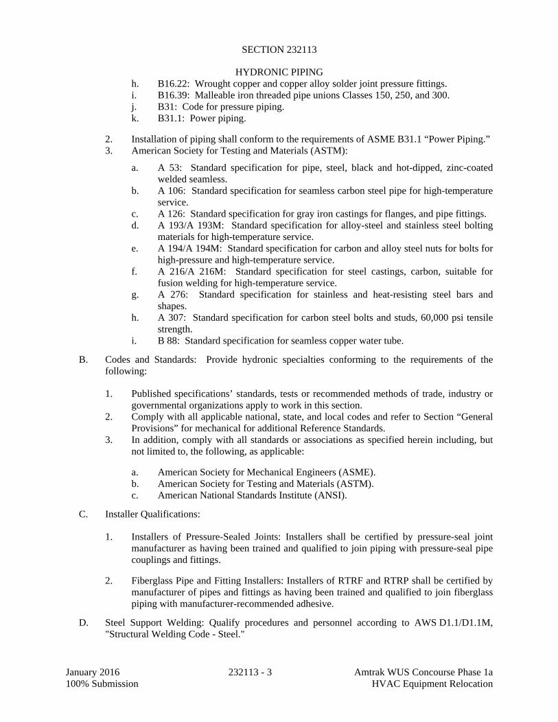
SECTION 232113
HYDRONIC PIPING
January 2016 232113 - 3 Amtrak WUS Concourse Phase 1a 100% Submission HVAC Equipment Relocation
h. B16.22: Wrought copper and copper alloy solder joint pressure fittings. i. B16.39: Malleable iron threaded pipe unions Classes 150, 250, and 300. j. B31: Code for pressure piping. k. B31.1: Power piping.
2. Installation of piping shall conform to the requirements of ASME B31.1 “Power Piping.” 3. American Society for Testing and Materials (ASTM):
a. A 53: Standard specification for pipe, steel, black and hot-dipped, zinc-coated welded seamless.
b. A 106: Standard specification for seamless carbon steel pipe for high-temperature service.
c. A 126: Standard specification for gray iron castings for flanges, and pipe fittings. d. A 193/A 193M: Standard specification for alloy-steel and stainless steel bolting
materials for high-temperature service. e. A 194/A 194M: Standard specification for carbon and alloy steel nuts for bolts for
high-pressure and high-temperature service. f. A 216/A 216M: Standard specification for steel castings, carbon, suitable for
fusion welding for high-temperature service. g. A 276: Standard specification for stainless and heat-resisting steel bars and
shapes. h. A 307: Standard specification for carbon steel bolts and studs, 60,000 psi tensile
strength. i. B 88: Standard specification for seamless copper water tube.
B. Codes and Standards: Provide hydronic specialties conforming to the requirements of the following:
1. Published specifications’ standards, tests or recommended methods of trade, industry or governmental organizations apply to work in this section.
2. Comply with all applicable national, state, and local codes and refer to Section “General Provisions” for mechanical for additional Reference Standards.
3. In addition, comply with all standards or associations as specified herein including, but not limited to, the following, as applicable:
a. American Society for Mechanical Engineers (ASME). b. American Society for Testing and Materials (ASTM). c. American National Standards Institute (ANSI).
C. Installer Qualifications:
1. Installers of Pressure-Sealed Joints: Installers shall be certified by pressure-seal joint manufacturer as having been trained and qualified to join piping with pressure-seal pipe couplings and fittings.
2. Fiberglass Pipe and Fitting Installers: Installers of RTRF and RTRP shall be certified by manufacturer of pipes and fittings as having been trained and qualified to join fiberglass piping with manufacturer-recommended adhesive.
D. Steel Support Welding: Qualify procedures and personnel according to AWS D1.1/D1.1M, "Structural Welding Code - Steel."

SECTION 232113
HYDRONIC PIPING
January 2016 232113 - 4 Amtrak WUS Concourse Phase 1a 100% Submission HVAC Equipment Relocation
E. Pipe Welding: Qualify procedures and operators according to ASME Boiler and Pressure Vessel Code: Section IX.
1. Comply with ASME B31.9, "Building Services Piping," for materials, products, and installation.
2. Certify that each welder has passed AWS qualification tests for welding processes involved and that certification is current.
PART 2 - PRODUCTS
2.1 PERFORMANCE REQUIREMENTS
A. Hydronic piping components and installation shall be capable of withstanding the following minimum working pressure and temperature unless otherwise indicated:
1. Hot-Water Heating Piping: 50 psig at 200 deg F. 2. Chilled-Water Piping: 50 psig at 200 deg F. 3. Condensate-Drain Piping: 150 deg F.
2.2 COPPER TUBE AND FITTINGS
A. Drawn-Temper Copper Tubing: ASTM B 88, Type L grooved piping. B. Annealed-Temper Copper Tubing: ASTM B 88, Type K. C. DWV Copper Tubing: ASTM B 306, Type DWV. D. Grooved, Mechanical-Joint, Wrought-Copper Fittings: ASME B16.22.
1. Manufacturers: Subject to compliance with requirements, provide products by one of the following:
a. Anvil International, Inc. b. S.P. Fittings; a division of Star Pipe Products. c. Victaulic Company of America.
2. Grooved-End Copper Fittings: ASTM B 75, copper tube or ASTM B 584, bronze casting. 3. Grooved-End-Tube Couplings: Rigid pattern unless otherwise indicated; gasketed fitting.
Ductile-iron housing with keys matching pipe and fitting grooves, EPDM gasket rated for minimum 230 deg F for use with housing, and steel bolts and nuts.
E. Copper or Bronze Pressure-Seal Fittings:
1. Manufacturers: Subject to compliance with requirements, provide products by one of the following:
a. NIBCO Inc. b. Viega LLC.
2. Housing: Copper. 3. O-Rings and Pipe Stops: EPDM. 4. Tools: Manufacturer's special tools. 5. Minimum 200-psig working-pressure rating at 250 deg F.
F. Copper, Mechanically Formed Tee Option: For forming T-branch on copper water tube.

SECTION 232113
HYDRONIC PIPING
January 2016 232113 - 5 Amtrak WUS Concourse Phase 1a 100% Submission HVAC Equipment Relocation
1. Manufacturers: Subject to compliance with requirements, provide products by one of the following:
a. T-DRILL Industries Inc.
G. Wrought-Copper Unions: ASME B16.22.
2.3 STEEL PIPE AND FITTINGS
A. Steel Pipe: ASTM A 53/A 53M, black steel with plain ends; welded and seamless, Grade B, and wall thickness as indicated in "Piping Applications" Article.
B. Cast-Iron Threaded Fittings: ASME B16.4; Classes 125 and 250 as indicated in "Piping Applications" Article.
C. Malleable-Iron Threaded Fittings: ASME B16.3, Classes 150 and 300 as indicated in "Piping Applications" Article.
D. Malleable-Iron Unions: ASME B16.39; Classes 150, 250, and 300 as indicated in "Piping Applications" Article.
E. Cast-Iron Pipe Flanges and Flanged Fittings: ASME B16.1, Classes 25, 125, and 250; raised ground face, and bolt holes spot faced as indicated in "Piping Applications" Article.
F. Wrought-Steel Fittings: ASTM A 234/A 234M, wall thickness to match adjoining pipe. G. Wrought Cast- and Forged-Steel Flanges and Flanged Fittings: ASME B16.5, including bolts,
nuts, and gaskets of the following material group, end connections, and facings:
1. Material Group: 1.1. 2. End Connections: Butt welding. 3. Facings: Raised face.
H. Grooved Mechanical-Joint Fittings and Couplings:
1. Manufacturers: Subject to compliance with requirements, provide products by one of the following:
a. Anvil International, Inc. b. Victaulic Company of America.
2. Joint Fittings: ASTM A 536, Grade 65-45-12 ductile iron; ASTM A 47/A 47M, Grade 32510 malleable iron; ASTM A 53/A 53M, Type F, E, or S, Grade B fabricated steel; or ASTM A 106/A 106M, Grade B steel fittings with grooves or shoulders constructed to accept grooved-end couplings; with nuts, bolts, locking pin, locking toggle, or lugs to secure grooved pipe and fittings.
3. Couplings: Ductile- or malleable-iron housing and EPDM or nitrile gasket of central cavity pressure-responsive design; with nuts, bolts, locking pin, locking toggle, or lugs to secure grooved pipe and fittings.
I. Steel Pressure-Seal Fittings:
1. Manufacturers: Subject to compliance with requirements, provide products by one of the following:
a. Victaulic Company of America.
2. Housing: Steel. 3. O-Rings and Pipe Stop: EPDM. 4. Tools: Manufacturer's special tool. 5. Minimum 300-psig working-pressure rating at 230 deg F.

SECTION 232113
HYDRONIC PIPING
January 2016 232113 - 6 Amtrak WUS Concourse Phase 1a 100% Submission HVAC Equipment Relocation
J. Steel Pipe Nipples: ASTM A 733, made of same materials and wall thicknesses as pipe in which they are installed.
2.4 PLASTIC PIPE AND FITTINGS 2.5 JOINING MATERIALS
A. Pipe-Flange Gasket Materials: Suitable for chemical and thermal conditions of piping system contents.
1. ASME B16.21, nonmetallic, flat, asbestos free, 1/8-inch maximum thickness unless otherwise indicated.
a. Full-Face Type: For flat-face, Class 125, cast-iron and cast-bronze flanges. b. Narrow-Face Type: For raised-face, Class 250, cast-iron and steel flanges.
B. Flange Bolts and Nuts: ASME B18.2.1, carbon steel, unless otherwise indicated. C. Plastic, Pipe-Flange Gasket, Bolts, and Nuts: Type and material recommended by piping system
manufacturer unless otherwise indicated.
D. Solder Filler Metals: ASTM B 32, lead-free alloys. Include water-flushable flux according to ASTM B 813.
E. Brazing Filler Metals: AWS A5.8/A5.8M, BCuP Series, copper-phosphorus alloys for joining copper with copper; or BAg-1, silver alloy for joining copper with bronze or steel.
F. Welding Filler Metals: Comply with AWS D10.12M/D10.12 for welding materials appropriate for wall thickness and chemical analysis of steel pipe being welded.
G. Solvent Cements for Joining Plastic Piping: H. Gasket Material: Thickness, material, and type suitable for fluid to be handled and working
temperatures and pressures.
2.6 TRANSITION FITTINGS 2.7 DIELECTRIC FITTINGS
A. General Requirements: Assembly of copper alloy and ferrous materials with separating nonconductive insulating material. Include end connections compatible with pipes to be joined.
B. Dielectric Unions:
1. Manufacturers: Subject to compliance with requirements, provide products by one of the following:
a. Capitol Manufacturing Company. b. Central Plastics Company. c. Hart Industries International, Inc. d. Watts Regulator Co.; a division of Watts Water Technologies, Inc. e. Zurn Industries, LLC.
2. Description:
a. Standard: ASSE 1079. b. Pressure Rating: 125 psig minimum at 180 deg F. c. End Connections: Solder-joint copper alloy and threaded ferrous.
C. Dielectric Flanges:

SECTION 232113
HYDRONIC PIPING
January 2016 232113 - 7 Amtrak WUS Concourse Phase 1a 100% Submission HVAC Equipment Relocation
1. Manufacturers: Subject to compliance with requirements, provide products by one of the following:
a. Capitol Manufacturing Company. b. Central Plastics Company. c. Watts Regulator Co.; a division of Watts Water Technologies, Inc. d. Zurn Industries, LLC.
2. Description:
a. Standard: ASSE 1079. b. Factory-fabricated, bolted, companion-flange assembly.
c. Pressure Rating: 125 psig minimum at 180 deg F . d. End Connections: Solder-joint copper alloy and threaded ferrous; threaded solder-
joint copper alloy and threaded ferrous.
D. Dielectric-Flange Insulating Kits:
1. Manufacturers: Subject to compliance with requirements, provide products by one of the following:
a. Advance Products & Systems, Inc. b. Calpico, Inc. c. Central Plastics Company. d. Pipeline Seal and Insulator, Inc.
2. Description:
a. Nonconducting materials for field assembly of companion flanges. b. Pressure Rating: 150 psig. c. Gasket: Neoprene or phenolic. d. Bolt Sleeves: Phenolic or polyethylene. e. Washers: Phenolic with steel backing washers.
E. Dielectric Nipples:
1. Manufacturers: Subject to compliance with requirements, provide products by one of the following:
a. Elster Perfection Corporation. b. Grinnell Mechanical Products. c. Matco - Norca. d. Precision Plumbing Products, Inc. e. Victaulic Company.
2. Description:
a. Standard: IAPMO PS 66. b. Electroplated steel nipple, complying with ASTM F 1545. c. Pressure Rating: 300 psig at 225 deg F. d. End Connections: Male threaded or grooved. e. Lining: Inert and noncorrosive, propylene.

SECTION 232113
HYDRONIC PIPING
January 2016 232113 - 8 Amtrak WUS Concourse Phase 1a 100% Submission HVAC Equipment Relocation
2.8 SLEEVES
A. Galvanized-Steel Sheet: 0.0239-inch minimum thickness; round tube closed with welded longitudinal joint.
B. Steel Pipe: ASTM A 53, Type E, Grade B, Schedule 40, galvanized, plain ends. C. Cast Iron: Cast or fabricated "wall pipe" equivalent to ductile-iron pressure pipe, with plain
ends and integral waterstop, unless otherwise indicated.
PART 3 - EXECUTION
3.1 PIPING APPLICATIONS
A. Hot-water heating piping, aboveground, NPS 2 and smaller , shall be any of the following:
1. Type L, drawn-temper copper tubing, wrought-copper fittings, and soldered joints. 2. Schedule 40, Grade B, socket weld end steel pipe or Schedule 80 threaded steel pipe;
Class 125, cast-iron fittings; cast-iron flanges and flange fittings; and threaded joints.
B. Hot-water heating piping, aboveground, NPS 2-1/2 and larger, shall be the following:
1. Type L, drawn-temper copper tubing, wrought-copper fittings, and soldered joints. 2. Schedule 40 steel pipe, wrought-steel fittings and wrought-cast or forged-steel flanges
and flange fittings, and welded and flanged joints. 3. Schedule 40 steel pipe; grooved, mechanical joint coupling and fittings; and grooved,
mechanical joints.
C. Chilled-water piping, aboveground, NPS 2 and smaller, shall be any of the following:
1. Type L, drawn-temper copper tubing, wrought-copper fittings, and soldered joints. 2. Schedule 40 or Schedule 80 steel pipe; Class 125, cast-iron fittings; cast-iron flanges and
flange fittings; and threaded joints.
D. Chilled-water piping, aboveground, NPS 2-1/2 and larger, shall be the following:
1. Type L, drawn-temper copper tubing, wrought-copper fittings, and soldered joints. 2. Schedule 40 steel pipe, wrought-steel fittings and wrought-cast or forged-steel flanges
and flange fittings, and welded and flanged joints. 3. Schedule 40 steel pipe; grooved, mechanical joint coupling and fittings; and grooved,
mechanical joints.
E. Condensate-Drain Piping: ASTM B 88, Type L drawn-temper copper tubing, wrought-copper fittings, and soldered joints.
3.2 PIPING INSTALLATIONS
A. Drawing plans, schematics, and diagrams indicate general location and arrangement of piping systems. Install piping as indicated unless deviations to layout are approved on Coordination Drawings.
B. Install piping in concealed locations unless otherwise indicated and except in equipment rooms and service areas.

SECTION 232113
HYDRONIC PIPING
January 2016 232113 - 9 Amtrak WUS Concourse Phase 1a 100% Submission HVAC Equipment Relocation
C. Install piping indicated to be exposed and piping in equipment rooms and service areas at right angles or parallel to building walls. Diagonal runs are prohibited unless specifically indicated otherwise.
D. Install piping to permit valve servicing. E. Install piping at indicated slopes. F. Install piping free of sags and bends. G. Install fittings for changes in direction and branch connections. H. Install piping to allow application of insulation. I. Select system components with pressure rating equal to or greater than system operating
pressure. J. Install groups of pipes parallel to each other, spaced to permit applying insulation and servicing
of valves. K. Install drains, consisting of a tee fitting, ball valve, and short threaded nipple with cap, at low
points in piping system mains and elsewhere as required for system drainage. Ball valve and threaded nipple with cap: Up to 6 inches pipe use NPS 3/4 and 8 inches and larger pipe use NPS 1-1/2.
L. Install piping at a uniform grade of 0.2 percent upward in direction of flow. M. Reduce pipe sizes using eccentric reducer fitting installed with level side up. Retain
"Mechanically Formed, Copper-Tube-Outlet Joints" Paragraph below for mechanically formed outlets in place of tee fittings in copper pipe. Use only with Owner’s approval as value engineering option.
N. Install unions in piping, NPS 2 and smaller, adjacent to valves, at final connections of equipment, and elsewhere as indicated.
O. Install flanges in piping, NPS 2-1/2 and larger, at final connections of equipment and elsewhere as indicated.
P. Install shutoff valve immediately upstream of each dielectric fitting. Q. Comply with requirements in Section 230516 "Expansion Fittings and Loops for HVAC
Piping" for installation of expansion loops, expansion joints, anchors, and pipe alignment guides.
R. Comply with requirements in Section 230553 "Identification for HVAC Piping and Equipment" for identifying piping.
S. Install sleeves for piping penetrations of walls, ceilings, and floors. Comply with requirements for sleeves specified in Section 230517 "Sleeves and Sleeve Seals for HVAC Piping."
T. Install strainers on inlet side of each control valve, pressure-reducing valve, solenoid valve, pump, and elsewhere as indicated.
3.3 DIELECTRIC FITTING INSTALLATION
A. Install dielectric fittings in piping at connections of dissimilar metal piping and tubing. B. Dielectric Fittings for NPS 2 and Smaller: Use dielectric unions. C. Dielectric Fittings for NPS 2-1/2 to NPS 4: Use dielectric flanges. D. Dielectric Fittings for NPS 5 and Larger: Use dielectric flange kits.
3.4 HANGERS AND SUPPORTS
A. Comply with requirements in Section 230529 "Hangers and Supports for HVAC Piping and Equipment" for hanger, support, and anchor devices. Comply with the following requirements for maximum spacing of supports.

SECTION 232113
HYDRONIC PIPING
January 2016 232113 - 10 Amtrak WUS Concourse Phase 1a 100% Submission HVAC Equipment Relocation
B. Comply with requirements in Section 230548 "Vibration Controls for HVAC" for seismic restraints.
C. Install the following pipe attachments:
1. Adjustable steel clevis hangers for individual horizontal piping less than 20 feet long. 2. Adjustable roller hangers and spring hangers for individual horizontal piping 20 feet or
longer. 3. Pipe Roller: MSS SP-58, Type 44 for multiple horizontal piping 20 feet or longer,
supported on a trapeze. 4. Spring hangers to support vertical runs. 5. Provide copper-clad hangers and supports for hangers and supports in direct contact with
copper pipe. 6. Supports of wire, rope, wood, chain, strap, perforated bar or any other makeshift device
will not be permitted. 7. Minimum spacing and minimum rod diameter shall comply with latest edition of MSS
SP-58.
D. Install hangers for steel piping with the following maximum spacing and minimum rod sizes:
1. NPS 3/4: Maximum span, 7 feet; minimum rod size, 3/8 inch. 2. NPS 1: Maximum span, 7 feet; minimum rod size, 3/8 inch. 3. NPS 1-1/4: Maximum span, 7 feet; minimum rod size, 3/8 inch. 4. NPS 1-1/2: Maximum span, 9 feet; minimum rod size, 3/8 inch. 5. NPS 2: Maximum span, 10 feet; minimum rod size, 3/8 inch. 6. NPS 2-1/2: Maximum span, 11 feet; minimum rod size, 1/2 inch. 7. NPS 3: Maximum span, 12 feet; minimum rod size, 1/2 inch. 8. NPS 4: Maximum span, 14 feet; minimum rod size, 5/8 inch. 9. NPS 6: Maximum span, 17 feet; minimum rod size, 3/4 inch. 10. NPS 8: Maximum span, 19 feet; minimum rod size, 3/4 inch. 11. NPS 10: Maximum span, 20 feet; minimum rod size, 7/8 inch.
E. Install hangers for drawn-temper copper piping with the following maximum spacing and minimum rod sizes:
1. NPS 3/4: Maximum span, 5 feet; minimum rod size, 3/8 inch. 2. NPS 1: Maximum span, 6 feet; minimum rod size, 3/8 inch. 3. NPS 1-1/4:Maximum span, 7 feet; minimum rod size, 3/8 inch. 4. NPS 1-1/2: Maximum span, 8 feet; minimum rod size, 3/8 inch. 5. NPS 2: Maximum span, 8 feet; minimum rod size, 3/8 inch. 6. NPS 2-1/2: Maximum span, 9 feet ; minimum rod size, ½ inch. 7. NPS 3: Maximum span, 10 feet; minimum rod size, ½ inch. 8. NPS 4: Maximum span, 12 feet; minimum rod size, ½ inch. 9. NPS 6: Maximum span, 14 feet; minimum rod size, 5/8 inch. 10. NPS 8: Maximum span, 16 feet; minimum rod size, 3/4 inch. 11. NPS 10: Maximum span, 18 feet; minimum rod size, 3/4 inch.
F. Support vertical runs at roof, at each floor.
1. Base Elbow Support: Provide bearing plate on structural support, similar to F&S Manufacturing Corp. Fig. 720.
2. Provide guides at every third floor but not to exceed:

SECTION 232113
HYDRONIC PIPING
January 2016 232113 - 11 Amtrak WUS Concourse Phase 1a 100% Submission HVAC Equipment Relocation
a. 25 ft. for piping to 2 inches. b. 36 ft. for piping 2-1/2 inches to 12 inches. c. 50 ft. for piping 14 inches and larger.
3. Top Support: Provide special hanger or saddle in horizontal connection and make provisions for expansion.
4. Intermediate Supports: Steel pipe clamp at floor. Bolt and weld to pipe with extension ends bearing on structural steel or bearing plates.
5. For multiple pipes, coordinate guides bearing plates and accessory steel.
3.5 PIPE JOINT CONSTRUCTION
A. Ream ends of pipes and tubes and remove burrs. Bevel plain ends of steel pipe. B. Remove scale, slag, dirt, and debris from inside and outside of pipe and fittings before
assembly. C. Soldered Joints: Apply ASTM B 813, water-flushable flux, unless otherwise indicated, to tube
end. Construct joints according to ASTM B 828 or CDA's "Copper Tube Handbook," using lead-free solder alloy complying with ASTM B 32.
D. Brazed Joints: Construct joints according to AWS's "Brazing Handbook," "Pipe and Tube" Chapter, using copper-phosphorus brazing filler metal complying with AWS A5.8/A5.8M.
E. Threaded Joints: Thread pipe with tapered pipe threads according to ASME B1.20.1. Cut threads full and clean using sharp dies. Ream threaded pipe ends to remove burrs and restore full ID. Join pipe fittings and valves as follows:
1. Apply appropriate tape or thread compound to external pipe threads unless dry seal threading is specified.
2. Damaged Threads: Do not use pipe or pipe fittings with threads that are corroded or damaged. Do not use pipe sections that have cracked or open welds.
F. Welded Joints: Construct joints according to AWS D10.12M/D10.12, using qualified processes and welding operators according to "Quality Assurance" Article.
G. Flanged Joints: Select appropriate gasket material, size, type, and thickness for service application. Install gasket concentrically positioned. Use suitable lubricants on bolt threads.
H. Grooved Joints: Assemble joints with coupling and gasket, lubricant, and bolts. Cut or roll grooves in ends of pipe based on pipe and coupling manufacturer's written instructions for pipe wall thickness. Use grooved-end fittings and rigid, grooved-end-pipe couplings.
I. Mechanically Formed, Copper-Tube-Outlet Joints: Use manufacturer-recommended tool and procedure, and brazed joints.
3.6 TERMINAL EQUIPMENT CONNECTIONS
A. Sizes for supply and return piping connections shall be the same as or larger than equipment connections.
B. Install control valves in accessible locations close to connected equipment. C. Install bypass piping with globe valve around control valve. If parallel control valves are
installed, only one bypass is required. D. Install ports for pressure gages and thermometers at coil inlet and outlet connections. Comply
with requirements in Section 230519 "Meters and Gages for HVAC Piping."
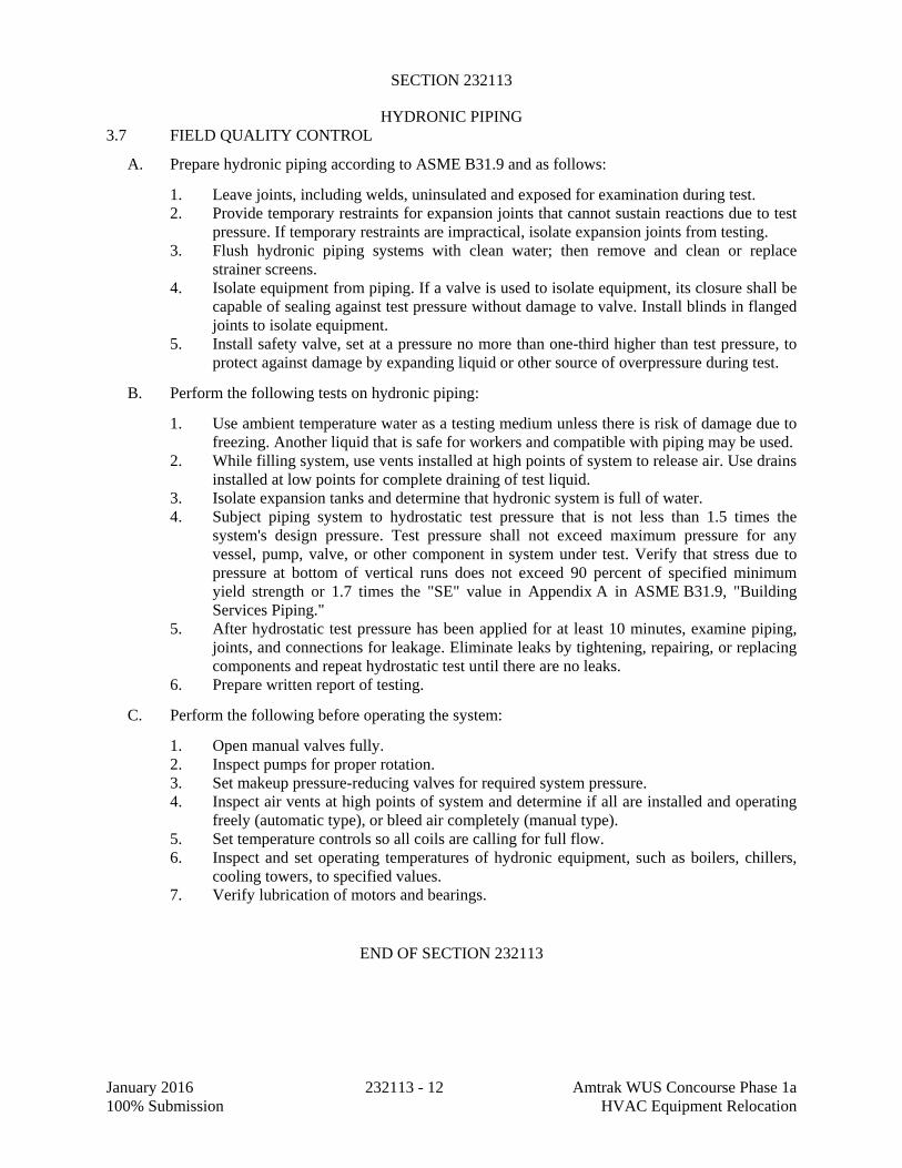
SECTION 232113
HYDRONIC PIPING
January 2016 232113 - 12 Amtrak WUS Concourse Phase 1a 100% Submission HVAC Equipment Relocation
3.7 FIELD QUALITY CONTROL
A. Prepare hydronic piping according to ASME B31.9 and as follows:
1. Leave joints, including welds, uninsulated and exposed for examination during test. 2. Provide temporary restraints for expansion joints that cannot sustain reactions due to test
pressure. If temporary restraints are impractical, isolate expansion joints from testing. 3. Flush hydronic piping systems with clean water; then remove and clean or replace
strainer screens. 4. Isolate equipment from piping. If a valve is used to isolate equipment, its closure shall be
capable of sealing against test pressure without damage to valve. Install blinds in flanged joints to isolate equipment.
5. Install safety valve, set at a pressure no more than one-third higher than test pressure, to protect against damage by expanding liquid or other source of overpressure during test.
B. Perform the following tests on hydronic piping:
1. Use ambient temperature water as a testing medium unless there is risk of damage due to freezing. Another liquid that is safe for workers and compatible with piping may be used.
2. While filling system, use vents installed at high points of system to release air. Use drains installed at low points for complete draining of test liquid.
3. Isolate expansion tanks and determine that hydronic system is full of water. 4. Subject piping system to hydrostatic test pressure that is not less than 1.5 times the
system's design pressure. Test pressure shall not exceed maximum pressure for any vessel, pump, valve, or other component in system under test. Verify that stress due to pressure at bottom of vertical runs does not exceed 90 percent of specified minimum yield strength or 1.7 times the "SE" value in Appendix A in ASME B31.9, "Building Services Piping."
5. After hydrostatic test pressure has been applied for at least 10 minutes, examine piping, joints, and connections for leakage. Eliminate leaks by tightening, repairing, or replacing components and repeat hydrostatic test until there are no leaks.
6. Prepare written report of testing.
C. Perform the following before operating the system:
1. Open manual valves fully. 2. Inspect pumps for proper rotation. 3. Set makeup pressure-reducing valves for required system pressure. 4. Inspect air vents at high points of system and determine if all are installed and operating
freely (automatic type), or bleed air completely (manual type). 5. Set temperature controls so all coils are calling for full flow. 6. Inspect and set operating temperatures of hydronic equipment, such as boilers, chillers,
cooling towers, to specified values. 7. Verify lubrication of motors and bearings.
END OF SECTION 232113

SECTION 232116
HYDRONIC PIPING SPECIALTIES
January 2016 232116 - 1 Amtrak WUS Concourse Phase 1a 100% Submission HVAC Equipment Relocation
PART 1 - GENERAL
1.1 RELATED DOCUMENTS
A. Drawings and general provisions of the Contract, including General and Supplementary Conditions, Division 01, and Division 23 Specification Sections, apply to this Section.
1.2 SUMMARY
A. Section includes special-duty valves and specialties for the following:
1. Hot-water heating piping. 2. Chilled-water piping. 3. Makeup-water piping. 4. Air-vent piping.
B. Specialties for above systems:
1. Expansion tanks. 2. Automatic and manual air vents. 3. Air separators. 4. Strainers. 5. Pressure Reducing Valves.
C. Related Sections:
1. Division 23 HVAC piping sections for specialty valves applicable to those sections only. 2. Division 23 Section "Identification for HVAC Piping and Equipment" for valve tags and
schedules. 3. Division 23 Section “HVAC Piping Insulation.” 4. Division 23 Section “HVAC Equipment Insulation.” 5. Division 23 Section “Instrumentation and Control for HVAC” for actuators and control
valves.
D. Definitions:
1. CWP: Cold working pressure. 2. EPDM: Ethylene propylene copolymer rubber.
1.3 SUBMITTALS
A. Action Submittals:
1. Product Data: Submit manufacturer’s standard technical product data indicating conformance to the stipulated reference specifications, construction materials, dimensions, construction details, and test and operating pressures. Submit manufacturer’s product data on the following:
a. Valves: Submit schedule listing type make and model number, size and service for valves, motorized valve operators, fittings, and equipment. Include flow and pressure drop curves based on manufacturer's testing for calibrated-orifice balancing valves and automatic flow-control valves.

SECTION 232116
HYDRONIC PIPING SPECIALTIES
January 2016 232116 - 2 Amtrak WUS Concourse Phase 1a 100% Submission HVAC Equipment Relocation
b. Air-control devices. c. Hydronic specialties: Submit schedule listing type, make and model number, size
and service for all hydronic specialties.
B. Closeout Submittals
1. Operation and Maintenance Data: For air-control devices, hydronic specialties, and special-duty valves to include in emergency, operation, and maintenance manuals.
C. Maintenance Material Submittals:
1. Differential Pressure Meter: For each type of balancing valve and automatic flow control valve, include flowmeter, probes, hoses, flow charts, and carrying case.
1.4 QUALITY ASSURANCE
A. Pipe Welding: Qualify procedures and operators according to ASME Boiler and Pressure Vessel Code: Section IX.
1. Safety valves and pressure vessels shall bear the appropriate ASME label. Fabricate and stamp air separators and expansion tanks to comply with ASME Boiler and Pressure Vessel Code: Section VIII, Division 1.
PART 2 - PRODUCTS
2.1 PERFORMANCE REQUIREMENTS
A. Hydronic piping components and installation shall be capable of withstanding the following minimum design pressure and temperature unless otherwise indicated:
1. Hot-Water Heating Piping: 100 psig at 200 deg F. 2. Chilled-Water Piping: 100 psig at 200 deg F. 3. Makeup-Water Piping: 80 psig at 150 deg F. 4. Air-Vent Piping: 200 deg F.
2.2 VALVES
A. Gate, Globe, Check, Ball, and Butterfly Valves: Comply with requirements specified in Section 230523.11 "Globe Valves for HVAC Piping," Section 230523.12 "Ball Valves for HVAC Piping," Section 230523.13 "Butterfly Valves for HVAC Piping," Section 230523.14 "Check Valves for HVAC Piping," and Section 230523.15 "Gate Valves for HVAC Piping."
B. Automatic Temperature-Control Valves, Actuators, and Sensors: Comply with requirements specified in Section 230923.11 “Control Valves”.
C. Diaphragm-Operated, Pressure-Reducing Valves: ASME labeled.
1. Manufacturers: Subject to compliance with requirements, provide products by one of the following:
a. Amtrol, Inc. b. Bell & Gossett; a Xylem brand. c. Conbraco Industries, Inc. d. Spence Engineering Company. e. Watts; a Watts Water Technologies Company.

SECTION 232116
HYDRONIC PIPING SPECIALTIES
January 2016 232116 - 3 Amtrak WUS Concourse Phase 1a 100% Submission HVAC Equipment Relocation
2. Body: Bronze or brass. 3. Disc: Glass and carbon-filled PTFE. 4. Seat: Brass. 5. Stem Seals: EPDM O-rings. 6. Diaphragm: EPT. 7. Low inlet-pressure check valve. 8. Inlet Strainer: removable without system shutdown. 9. Valve Seat and Stem: Noncorrosive. 10. Valve Size, Capacity, and Operating Pressure: Selected to suit system in which installed,
with operating pressure and capacity factory set and field adjustable.
2.3 AIR-CONTROL DEVICES
A. Manual Air Vents:
1. Manufacturers: Subject to compliance with requirements, provide products by one of the following:
a. Amtrol, Inc. b. Armstrong Pumps, Inc. c. Bell & Gossett; a Xylem brand. d. Nu Tech Hydronic Specialty Products. e. Taco.
2. Body: Bronze. 3. Internal Parts: Nonferrous. 4. Operator: Screwdriver or thumbscrew. 5. Inlet Connection: NPS 1/2. 6. Discharge Connection: NPS 1/8. 7. CWP Rating: 150 psig. 8. Maximum Operating Temperature: 225 deg F.
B. Automatic Air Vents:
1. Manufacturers: Subject to compliance with requirements, provide products by one of the following:
a. Amtrol, Inc. b. Armstrong Pumps, Inc. c. Bell & Gossett; a Xylem brand. d. Nu Tech Hydronic Specialty Products. e. Taco.
2. Body: Bronze or cast iron. 3. Internal Parts: Nonferrous. 4. Operator: Noncorrosive metal float. 5. Inlet Connection: NPS 1/2. 6. Discharge Connection: NPS 1/4. 7. CWP Rating: 150 psig. 8. Maximum Operating Temperature: 240 deg F.
C. Expansion Tanks:

SECTION 232116
HYDRONIC PIPING SPECIALTIES
January 2016 232116 - 4 Amtrak WUS Concourse Phase 1a 100% Submission HVAC Equipment Relocation
1. Manufacturers: Subject to compliance with requirements, provide products by one of the following:
a. Amtrol, Inc. b. Armstrong Pumps, Inc. c. Bell & Gossett; a Xylem brand. d. Taco.
2. Tank: Welded steel, rated for 125-psig design pressure and 375 deg F maximum operating temperature, with taps in bottom of tank for tank fitting and taps in end of tank for gage glass. Tanks shall be factory tested after taps are fabricated and shall be labeled according to ASME Boiler and Pressure Vessel Code: Section VIII, Division 1.
3. Air-Control Tank Fitting: Cast-iron body, copper-plated tube, brass vent tube plug, and stainless-steel ball check, 100-gal.unit only; sized for compression-tank diameter. Provide tank fittings for 125-psig design pressure and 250 deg F maximum operating temperature.
4. Tank Drain Fitting: Brass body, nonferrous internal parts; 125-psig design pressure and 240 deg F maximum operating temperature; constructed to admit air to compression tank, drain water, and close off system.
5. Gage Glass: Full height with dual manual shutoff valves, 3/4-inch- diameter gage glass, and slotted-metal glass guard.
6. High and low water alarm switches, similar to McDonnell Miller Type 63, to actuate high and low water alarm.
7. Tank provided with integral base mount or factory furnished saddles.
D. Bladder-Type Expansion Tanks:
1. Manufacturers: Subject to compliance with requirements, provide products by one of the following:
a. Amtrol, Inc. b. Armstrong Pumps, Inc. c. Bell & Gossett; a Xylem brand. d. Taco.
2. Tank: Welded steel, rated for 125-psig design pressure and 375 deg F maximum operating temperature. Factory test after taps are fabricated and supports installed and are labeled according to ASME Boiler and Pressure Vessel Code: Section VIII, Division 1.
3. Bladder: Securely sealed into tank to separate air charge from system water to maintain required expansion capacity.
4. Air-Charge Fittings: Schrader valve, stainless steel with EPDM seats. 5. Tank provided with integral base mount or factory furnished saddles.
E. Tangential-Type Air Separators:
1. Manufacturers: Subject to compliance with requirements, provide products by one of the following:
a. Amtrol, Inc. b. Armstrong Pumps, Inc. c. Bell & Gossett; a Xylem brand. d. Taco.
2. Tank: Welded steel; ASME constructed and labeled for 125-psig minimum design pressure and 375 deg Fmaximum operating temperature.

SECTION 232116
HYDRONIC PIPING SPECIALTIES
January 2016 232116 - 5 Amtrak WUS Concourse Phase 1a 100% Submission HVAC Equipment Relocation
3. Air Collector Tube: Perforated stainless steel, constructed to direct released air into expansion tank.
4. Tangential Inlet and Outlet Connections: Threaded for NPS 2 and smaller; flanged connections for NPS 2-1/2 and larger.
5. Blowdown Connection: Threaded. 6. Size: Match system flow capacity.
2.4 HYDRONIC PIPING SPECIALTIES
A. Y-Pattern Strainers:
1. Body: ASTM A 126, Class B, cast iron with bolted cover and bottom drain connection. 2. End Connections: Threaded ends for NPS 2 and smaller; flanged ends for NPS 2-1/2 and
larger.
3. Strainer Screen: Stainless-steel, 40-mesh strainer, or perforated stainless-steel basket. 4. CWP Rating: 125 psig.
B. Stainless-Steel Bellow, Flexible Connectors:
1. Body: Stainless-steel bellows with woven, flexible, bronze, wire-reinforcing protective jacket.
2. End Connections: Threaded or flanged to match equipment connected. 3. Performance: Capable of 3/4-inch misalignment. 4. CWP Rating: 150 psig. 5. Maximum Operating Temperature: 250 deg F.
C. Spherical, Rubber, Flexible Connectors:
1. Body: Fiber-reinforced rubber body. 2. End Connections: Steel flanges drilled to align with Classes 150 and 300 steel flanges. 3. Performance: Capable of misalignment. 4. CWP Rating: 150 psig. 5. Maximum Operating Temperature: 250 deg F.
PART 3 - EXECUTION
3.1 VALVE APPLICATIONS A. Install pressure-reducing valves at makeup-water connection to regulate system fill pressure.
3.2 HYDRONIC SPECIALTIES INSTALLATION
A. Install manual air vents at high points in piping, at heat-transfer coils, and elsewhere as required for system air venting.
B. Install automatic air vents at high points of system piping in mechanical equipment rooms only. Install manual vents at heat-transfer coils and elsewhere as required for air venting.
C. Install tangential air separator in pump suction. Install blowdown piping with gate or full-port ball valve; extend full size to nearest floor drain.
D. Install expansion tanks above the air separator. Install tank fitting in tank bottom and charge tank. Use manual vent for initial fill to establish proper water level in tank.

SECTION 232116
HYDRONIC PIPING SPECIALTIES
January 2016 232116 - 6 Amtrak WUS Concourse Phase 1a 100% Submission HVAC Equipment Relocation
1. Install tank fittings that are shipped loose. 2. Support tank from floor or structure above with sufficient strength to carry weight of
tank, piping connections, fittings, plus tank full of water. Do not overload building components and structural members.
E. Vent and purge air from hydronic system, and ensure that tank is properly charged with air or nitrogen to suit system project requirements. Charge the diaphragm/bladder type expansion tank with air prior to filling the piping system with fluid. The tank shall be charged to a pressure as indicated in the tank schedule on design documents.
END OF SECTION 232116

SECTION 232123
HYDRONIC PUMPS
January 2016 232123 - 1 Amtrak WUS Concourse Phase 1a100% Submission HVAC Equipment Relocation
PART 1 - GENERAL
1.1 RELATED DOCUMENTS
A. Drawings and general provisions of the Contract, including General Requirements Division 01, Division 23 Specification Sections, and Common Work Requirements for HVAC apply to the work specified in this Section.
1.2 SUMMARY
A. This Section includes the following:
1. Close-coupled, in-line centrifugal pumps. 2. Separately coupled, vertical, in-line centrifugal pumps.
1.3 DEFINITIONS
A. Buna-N: Nitrile rubber.
B. EPT: Ethylene propylene terpolymer.
C. HI: Hydraulic Institute.
1.4 SUBMITTALS
A. Product Data: Include certified performance curves and rated capacities, power requirement, operating characteristics, furnished specialties, final impeller dimensions, material specifications, and accessories for each type of product indicated. Indicate pump's operating point on curves, including NPSH curves.
B. Shop Drawings: Show pump layout and connections. Include setting drawings with templates for installing foundation and anchor bolts and other anchorages.
1. Wiring Diagrams: Power, signal, and control wiring.
C. Operation and Maintenance Data: For pumps to include in emergency, operation, and maintenance manuals.
1.5 QUALITY ASSURANCE
A. Source Limitations: Obtain hydronic pumps through one source from a single manufacturer.

SECTION 232123
HYDRONIC PUMPS
January 2016 232123 - 2 Amtrak WUS Concourse Phase 1a100% Submission HVAC Equipment Relocation
B. Product Options: Drawings indicate size, profiles, and dimensional requirements of hydronic pumps and are based on the specific system indicated. Refer to Division 01 Section "Product Requirements."
C. Electrical Components, Devices, and Accessories: Listed and labeled as defined in NFPA 70, Article 100, by a testing agency acceptable to authorities having jurisdiction, and marked for intended use.
D. UL Compliance: Comply with UL 778 for motor-operated water pumps.
E. Pump Performance: Ensure pumps operate at specified system fluid temperatures without vapor binding and cavitation, are non-overloading in parallel or individual operation, and operate within 25% of midpoint of published maximum efficiency curve.
F. Pump tests: Manufacturer shall test pumps in the shop prior to shipment. For identical pumps, only one pump of each specified capacity need to be tested. Tests shall be in accordance with the Hydraulic Institute Test Code.
1.6 DELIVERY, STORAGE, AND HANDLING
A. Manufacturer's Preparation for Shipping: Clean flanges and exposed machined metal surfaces and treat with anticorrosion compound after assembly and testing. Protect flanges, pipe openings, and nozzles with wooden flange covers or with screwed-in plugs.
B. Store pumps in dry location.
C. Retain protective covers for flanges and protective coatings during storage.
D. Protect bearings and couplings against damage from sand, grit, and other foreign matter.
E. Comply with pump manufacturer's written rigging instructions.
1.7 COORDINATION
A. Coordinate size and location of concrete bases. Cast anchor-bolt inserts into bases. Concrete, reinforcement, and formwork requirements are specified in Division 03.
1.8 EXTRA MATERIALS
A. Furnish extra materials described below that match products installed and that are packaged with protective covering for storage and identified with labels describing contents.
1. Mechanical Seals: One mechanical seal(s) for each pump.

SECTION 232123
HYDRONIC PUMPS
January 2016 232123 - 3 Amtrak WUS Concourse Phase 1a100% Submission HVAC Equipment Relocation
PART 2 - PRODUCTS
2.1 MANUFACTURERS
A. In other Part 2 articles where titles below introduce lists, the following requirements apply to product selection:
1. Manufacturers: Subject to compliance with requirements, provide products by one of the manufacturers specified.
2.2 GENERAL
A. Factory assembled, packaged and motor.
B. Centrifugal: Single stage, unless otherwise noted.
C. Statically and dynamically balance rotating parts.
D. Pumps to operate at 1750 rpm unless specified otherwise.
E. Pump and motor capacities:
1. Minimum as scheduled on Drawings. 2. Suitable for parallel operation. 3. Motor to operate over entire head capacity range of pump without exceeding horsepower
rating. 4. Motors shall be “High-Efficiency” type specified in Division 23 Section “Common
Motor Requirements for HVAC Equipment.”
F. Pump characteristics:
1. Pump curve shall rise continuously from maximum capacity to shutoff. 2. Shutoff head shall be approximately 10% greater than design head. 3. Operation shall be at or near peak efficiency. 4. Capable of operating at 25% beyond design capacity in gpm without exceeding break off
point. 5. Impeller diameter: Maximum 90% difference between maximum and minimum of
published impeller diameter. 6. Scheduled maximum NPSH required to apply over full operating range of pump.
G. Tested and guaranteed to withstand 1 1/2 times specified working pressures.
H. Pumps to be suitable for handling fluids at scheduled temperatures.
I. Abrasive Separator: Except as noted, provide seal flush piping connections with stainless steel abrasive separator.

SECTION 232123
HYDRONIC PUMPS
January 2016 232123 - 4 Amtrak WUS Concourse Phase 1a100% Submission HVAC Equipment Relocation
2.3 CLOSE-COUPLED, IN-LINE CENTRIFUGAL PUMPS
A. Manufacturers:
1. Armstrong Pumps Inc. 2. Aurora Pump; Division of Pentair Pump Group. 3. Bell & Gossett; Div. of ITT Industries. 4. Grundfos Pumps Corporation. 5. PACO Pumps. 6. Patterson Pump Co.; a Subsidiary of The Gorman-Rupp Co. 7. Taco, Inc. 8. Thrush Company Inc. 9. Weinman; Div. of Crane Pumps & Systems.
B. Description: Factory-assembled and -tested, centrifugal, overhung-impeller, close-coupled, in-line pump as defined in HI 1.1-1.2 and HI 1.3; designed for installation with pump and motor shafts mounted vertically. Rate pump for 175-psig minimum working pressure and a continuous water temperature of 200 deg F.
C. Pump Construction:
1. Casing: Radially split, cast iron, with replaceable bronze wear rings, threaded gage tappings at inlet and outlet, and threaded companion-flange connections.
2. Impeller: ASTM B 584, cast bronze; statically and dynamically balanced, keyed to shaft, and secured with a locking cap screw. Trim impeller to match specified performance.
3. Pump Shaft: Stainless steel. 4. Mechanical Seal: Carbon rotating ring against a ceramic seat held by a stainless-steel
spring, and Buna-N bellows and gasket. Include water slinger on shaft between motor and seal.
5. Packed Seal: Stuffing box, with a minimum of four rings of graphite-impregnated braided yarn with bronze lantern ring between center two graphite rings, and bronze packing gland.
6. Pump Bearings: Oil lubricated; bronze-journal or thrust type.
D. Motor: Single speed, with grease-lubricated ball bearings, unless otherwise indicated; and rigidly mounted to pump casing. Comply with requirements in Division 23 Section "Common Motor Requirements for HVAC Equipment."
E. Capacities and Characteristics: As scheduled on Drawings.
2.4 SEPARATELY COUPLED, VERTICAL, IN-LINE TWIN CENTRIFUGAL PUMPS
A. Manufacturers:
1. Armstrong Pumps Inc.
B. Description: Factory-assembled and -tested, centrifugal, overhung-impeller, separately coupled, in-line pump as defined in HI 1.1-1.2 and HI 1.3; designed for installation with pump and motor

SECTION 232123
HYDRONIC PUMPS
January 2016 232123 - 5 Amtrak WUS Concourse Phase 1a100% Submission HVAC Equipment Relocation
shafts mounted vertically on a cast iron support stand. Rate pump for 125-psig minimum working pressure and a continuous water temperature of 200 deg F.
C. Pump Construction:
1. Casing: Radially split, cast iron, with replaceable bronze wear rings, threaded gage tappings at inlet and outlet, and threaded companion-flange connections.
2. Impeller: ASTM B 584, cast bronze; statically and dynamically balanced, keyed to shaft, and secured with a locking cap screw. Trim impeller to match specified performance.
3. Pump Shaft: Stainless steel. 4. Mechanical Seal: Carbon rotating ring against a ceramic seat held by a stainless-steel
spring, and Viton, Buna-N, EPT, or approved equal bellows and gasket. Include water slinger on shaft between motor and seal.
5. Packed Seal: Stuffing box, with a minimum of four rings of non-asbestos, graphite-impregnated braided yarn with bronze lantern ring between center two graphite rings, and bronze packing gland.
D. Shaft Coupling: Axially split spacer coupling.
E. Motor: Single speed, unless otherwise indicated; rigidly mounted to pump casing with lifting eye and supporting lugs in motor enclosure. Comply with requirements in Division 23 Section "Common Motor Requirements for HVAC Equipment."
F. Capacities and Characteristics: As scheduled on Drawings.
PART 3 - EXECUTION
3.1 EXAMINATION
A. Examine roughing-in for piping systems to verify actual locations of piping connections before pump installation.
B. Proceed with installation only after unsatisfactory conditions have been corrected.
3.2 PUMP INSTALLATION
A. Comply with HI 2.4.
B. Install pumps with access for periodic maintenance including removal of motors, impellers, couplings, and accessories.
C. Independently support pumps and piping so weight of piping is not supported by pumps and weight of pumps is not supported by piping. Provide supports under elbows on pump suction and discharge lines 8 inches and over.
D. Install continuous-thread hanger rods and spring hangers of sufficient size to support pump weight. Vibration isolation devices are specified in Division 23 Section "Vibration Controls for

SECTION 232123
HYDRONIC PUMPS
January 2016 232123 - 6 Amtrak WUS Concourse Phase 1a100% Submission HVAC Equipment Relocation
HVAC Piping and Equipment." Fabricate brackets or supports as required. Hanger and support materials are specified in Division 23 Section "Hangers and Supports for HVAC Piping and Equipment."
E. Suspend vertically mounted, in-line centrifugal pumps independent of piping. Install pumps with motor and pump shafts vertical. Use continuous-thread hanger rods and spring hangers of sufficient size to support pump weight. Vibration isolation devices are specified in Division 21 Section "Vibration and Seismic Controls for Fire-Suppression Piping and Equipment." Hanger and support materials are specified in Division 22 Section "Hangers and Supports for Plumbing Piping and Equipment/Hangers and Supports for HVAC Piping and Equipment."
3.3 ALIGNMENT
A. Align pump and motor shafts and piping connections after setting on foundation, grout has been set and foundation bolts have been tightened, and piping connections have been made.
B. Comply with pump and coupling manufacturers' written instructions.
C. Adjust pump and motor shafts for angular and offset alignment by methods specified in HI 2.1-2.5, "Vertical Pumps for Nomenclature, Definitions, Application and Operation."
D. After alignment is correct, tighten foundation bolts evenly but not too firmly. Completely fill baseplate with nonshrink, nonmetallic grout while metal blocks and shims or wedges are in place. After grout has cured, fully tighten foundation bolts.
3.4 CONNECTIONS
A. Piping installation requirements are specified in other Division 23 Sections. Drawings indicate general arrangement of piping, fittings, and specialties.
B. Install piping adjacent to machine to allow service and maintenance.
C. Connect piping to pumps. Install valves that are same size as piping connected to pumps.
D. Install suction and discharge pipe sizes equal to or greater than diameter of pump nozzles. Decrease to pump nozzles from line size with long radium reducing elbows or reducers.
E. Install silent spring loaded check valve on discharge side of pumps.
F. Install Y-type strainer and shutoff valve on suction side of pumps.
G. Install flexible connectors on suction and discharge sides of base-mounted pumps between pump casing and valves.
H. Install pressure gages on pump suction and discharge, at integral pressure-gage tapping.
I. Install check valve and gate or ball valve on each condensate pump unit discharge.
J. Provide drains from baseplates and stuffing boxes, piped to spill over floor drains.

SECTION 232123
HYDRONIC PUMPS
January 2016 232123 - 7 Amtrak WUS Concourse Phase 1a100% Submission HVAC Equipment Relocation
K. Provide vent valves and drain on pump casings.
L. Pipe up flush filter for mechanical seals, with bypass line from pump discharge to external gland connection and filter or cyclone separator in line.
M. Install electrical connections for power, controls, and devices.
N. Ground equipment according to Division 26 Section "Grounding and Bonding for Electrical Systems."
O. Connect wiring according to Division 26 Section "Low-Voltage Electrical Power Conductors and Cables."
3.5 STARTUP SERVICE
A. Engage a factory-authorized service representative to perform startup service.
1. Complete installation and startup checks according to manufacturer's written instructions. 2. Check piping connections for tightness. 3. Clean strainers on suction piping. 4. Perform the following startup checks for each pump before starting:
a. Verify bearing lubrication. b. Verify that pump is free to rotate by hand and that pump for handling hot liquid is
free to rotate with pump hot and cold. If pump is bound or drags, do not operate until cause of trouble is determined and corrected.
c. Verify that pump is rotating in the correct direction.
5. Prime pump by opening suction valves and closing drains, and prepare pump for operation.
6. Start motor. 7. Open discharge valve slowly.
3.6 DEMONSTRATION
A. Engage a factory-authorized service representative to train Owner's maintenance personnel to adjust, operate, and maintain hydronic pumps. Refer to Division 01 Section "Demonstration and Training."
END OF SECTION

SECTION 232213
STEAM AND CONDENSATE HEATING PIPING
January 2016 232213 - 1 Amtrak WUS Concourse Phase 1a 100% Submission HVAC Equipment Relocation
PART 1 - GENERAL
1.1 RELATED DOCUMENTS
A. Drawings and general provisions of the Contract, including General Requirements Division 01, Division 23 Specification Sections, and Common Work Requirements for HVAC apply to the work specified in this Section.
1.2 SUMMARY
A. This Section includes the following for LP, MP and HP steam, condensate and pumped condensate piping:
1. Pipe and fittings. 2. Strainers. 3. Flash tanks. 4. Steam traps. 5. Thermostatic air vents and vacuum breakers.
1.3 DEFINITIONS
A. HP and MP Systems: High-pressure piping and medium pressure piping operating at more than 15 psig as required by ASME B31.1.
B. LP Systems: Low-pressure piping operating at 15 psig or less as required by ASME B31.9.
1.4 PERFORMANCE REQUIREMENTS
A. Components and installation shall be capable of withstanding the following minimum working pressures and temperatures:
1. HP Steam Piping: up to 200 psig 2. MP Steam Piping: up to 100 psig 3. LP Steam Piping: up to 15 psig 4. Condensate Piping: 100 psig at 250 deg F. 5. Air-Vent and Vacuum-Breaker Piping: Equal to pressure of the piping system to which it
is attached. 6. Safety-Valve-Inlet and -Outlet Piping: Equal to pressure of the piping system to which it
is attached.
1.5 SUBMITTALS
A. Product Data: For each type of the following: 1. Steam trap.

SECTION 232213
STEAM AND CONDENSATE HEATING PIPING
January 2016 232213 - 2 Amtrak WUS Concourse Phase 1a 100% Submission HVAC Equipment Relocation
2. Air vent and vacuum breaker. 3. Flash tank. 4. Pipe and fittings. 5. Unions and flanges. 6. Gaskets. 7. Sleeves and packing.
B. Shop Drawings: Detail, 1/4 inch equals 1 foot scale, flash tank assemblies and fabrication of pipe anchors, hangers, pipe, multiple pipes, alignment guides, and expansion joints and loops and their attachment to the building structure. Detail locations of anchors, alignment guides, and expansion joints and loops. Provide shop drawings for the following locations: 1. Mechanical equipment layouts. 2. Heat exchangers. 3. All floor plan layouts.
C. Qualification Data: For Installer.
D. Welding certificates.
E. Field quality-control test reports.
F. Operation and Maintenance Data: For valves, safety valves, pressure-reducing valves, steam traps, air vents, vacuum breakers, and meters to include in emergency, operation, and maintenance manuals.
G. Schedules: Submit a schedule of pipe materials, fittings, unions, and flanges, along with ratings, for each system.
H. Submit stress calculations upon request.
I. Submit calculations for anchors upon request.
1.6 QUALITY ASSURANCE
A. Installer Qualifications:
B. Steel Support Welding: Qualify processes and operators according to AWS D1.1, "Structural Welding Code - Steel."
C. Pipe Welding: Qualify processes and operators according to the following:
1. Comply with provisions in ASME B31 Series, "Code for Pressure Piping." 2. Certify that each welder has passed AWS qualification tests for welding processes
involved and that certification is current.
D. ASME Compliance: Comply with ASME B31.1, "Power Piping” and ASME B31.9, "Building Services Piping" for materials, products, and installation. Safety valves and pressure vessels shall bear the appropriate ASME label. Fabricate and stamp flash tanks to comply with ASME Boiler and Pressure Vessel Code: Section VIII, Division 1.

SECTION 232213
STEAM AND CONDENSATE HEATING PIPING
January 2016 232213 - 3 Amtrak WUS Concourse Phase 1a 100% Submission HVAC Equipment Relocation
E. Codes and Standards: Provide steam and steam condensate piping and specialties conforming to the following: 1. American Society of Mechanical Engineers (ASME):
a. B16.1: Cast iron threaded flanges and fittings. b. B16.3: Malleable iron threaded fittings. c. B16.4: Cast iron threaded fittings. d. B16.5: Wrought steel flanges and flanged fittings. e. B16.9: Factory-made wrought steel buttwelding fittings. f. B16.11: Forged steel fittings, socket-welding and threaded. g. B16.39: Malleable iron threaded pipe unions classes 150, 250, and 300. h. B31: Code for pressure piping. i. B31.1: Power piping. j. Z49.1: Safety in welding and cutting.
2. American Society for Testing and Materials (ASTM): a. A53: Standard Specification for Pipe, Steel, Black and Hot-Dipped, Zinc-Coated
Welded Seamless. b. A105/105M: Standard Specification for Forgings, Carbon Steel for Piping
Components. c. A106: Standard Specification for Seamless Carbon Steel Pipe for High
Temperature Service. d. A126: Standard Specification for Gray Iron Castings for Valves, Flanges, and
Pipe Fittings. e. A193/193M: Standard Specification for Alloy-Steel and Stainless Steel Bolting
Materials for High Temperature Services. f. A194/194M: Standard Specification for Carbon and Alloy Steel Nuts for Bolts for
High Pressure and High Temperature Service. g. A216/216M: Standard Specification for Steel Castings, Carbon, Suitable for
Fusion Welding for High Temperature Service. h. A234/234M: Standard Specification for Piping Fittings of Wrought Carbon Steel
and Alloy Steel for Moderate and High Temperature Service. i. A307: Standard Specification for Carbon Steel Bolts and Studs, 60,000 Tensile
Strength. j. B61: Standard Specification for Steam or Valve Bronze Castings. k. B62: Standard Specification for Composition Bronze or Ounce Metal Castings.
3. American Welding Society, Inc. (AWS): Welding and safety procedure shall conform to the requirements of the AWS B2.1, “Welding Procedure and Performance Qualification,” and ANSI Z491, “Safety in Welding and Cutting.”
F. Qualification of Welders: Welders performing work under this Contract shall be certified and qualified in accordance with tests prescribed by the National Certified Welding Bureau (NCWB) or by other approved test procedures using methodology and procedures covered in the ASME Boiler and Pressure Vessel Code, Section IX, “Qualification Standard for Welding and Brazing Procedures, Welders, Brazers, and Welding and Brazing Operators.” 1. Submit for approval names, identification, and welder’s assigned number, letter or
symbol for each welder assigned to this project. 2. The assigned identification symbol shall be used to identify the work of each welder and
shall be indelibly stamped immediately upon completion of each weld. 3. Welders shall be tested and certified for all positions. 4. Submit identifying stenciled test coupons made by each operator, if requested. 5. Welder will retake welding certifying test, at no additional expense if requested.

SECTION 232213
STEAM AND CONDENSATE HEATING PIPING
January 2016 232213 - 4 Amtrak WUS Concourse Phase 1a 100% Submission HVAC Equipment Relocation
6. When so requested, a welder shall not be permitted to work as a welder on this project until he has been recertified in accordance with NCWB.
7. Recertification of the welder shall be resubmitted after the welder has taken and passed the required tests.
8. Where piping 1-1/2 inches and smaller is butt or socket welded, submit 3 samples of test welds for approval.
G. Qualifications of Radiographic Examiner: Personnel conducting radiographic examinations shall conform to the qualification requirements of the American Society for Nondestructive Testing, Inc. (ASNT) Publication SNT-TC-1A, “Recommended Practice for Personnel Qualifications and Certification.”
H. Published specifications standards, tests, or recommended methods or trade, industry or governmental organizations apply to work in this section.
1.7 STORAGE AND PROTECTION
A. Storage: Store piping on this project site so as to preclude the entrance of construction dirt and debris into the open ends of piping. Do not install piping fouled with construction dirt.
B. Storage of Fittings: Store fittings under cover, protected from construction dirt and rain.
PART 2 - PRODUCTS
2.1 STEEL PIPE AND FITTINGS
A. Steel Pipe: ASTM A 53/A 53M, black steel, plain ends, Type, Grade, and Schedule as indicated in Part 3 piping applications articles.
B. Cast-Iron Threaded Fittings: ASME B16.4; Classes 125, 150, and 300 as indicated in Part 3 piping applications articles.
C. Malleable-Iron Threaded Fittings: ASME B16.3; Classes 150 and 300 as indicated in Part 3 piping applications articles.
D. Malleable-Iron Unions: ASME B16.39; Classes 150, 250, and 300 as indicated in Part 3 piping applications articles.
E. Cast-Iron Threaded Flanges and Flanged Fittings: ASME B16.1, Classes 125 and 250 as indicated in Part 3 piping applications articles; raised ground face, and bolt holes spot faced.
F. Wrought-Steel Fittings: ASTM A 234/A 234M, butt weld type, wall thickness to match adjoining pipe.
G. Wrought-Steel Flanges and Flanged Fittings: ASME B16.5, including bolts, nuts, and gaskets of the following material group, end connections, and facings:
1. Material Group: 1.1.

SECTION 232213
STEAM AND CONDENSATE HEATING PIPING
January 2016 232213 - 5 Amtrak WUS Concourse Phase 1a 100% Submission HVAC Equipment Relocation
2. End Connections: Butt welding. 3. Facings: Raised face.
H. Forged Steel Fittings: ASME 16.11: Class 2000 (threaded) and Class 3000 (socket welded) as indicated in Part 3 piping applications articles.
I. Steel Pipe Nipples: ASTM A 733, made of ASTM A 53/A 53M, black steel of same Type, Grade, and Schedule as pipe in which installed.
J. Stainless-Steel Bellows, Flexible Connectors:
1. Body: Stainless-steel bellows with woven, flexible, bronze, wire-reinforced, protective jacket.
2. End Connections: Threaded or flanged to match equipment connected. 3. Performance: Capable of 3/4-inch misalignment. 4. CWP Rating: 150-psig. 5. Maximum Operating Temperature: 250 deg F.
2.2 JOINING MATERIALS
A. Pipe-Flange Gasket Materials: Suitable for chemical and thermal conditions of piping system contents.
1. ASME B16.21, nonmetallic, flat, asbestos free, 1/8-inch maximum thickness unless thickness or specific material is indicated.
a. Full-Face Type: For flat-face, Class 125, cast-iron and cast-bronze flanges. b. Narrow-Face Type: For raised-face, Class 250, cast-iron and steel flanges.
2. ASME B16.20, metallic, spiral wound, asbestos free, 1/8 inch maximum thickness, for services above 250 deg F.
B. Flange Bolts and Nuts: ASME B18.2.1, carbon steel, unless otherwise indicated.
1. Bolts: ASTM A193 Grade B7, chrome-molybdenum bolt stud, with full length threads. 2. Nuts: ASTM A194 Grade 2, carbon steel, hexagon heavy series type.
C. Welding Filler Metals: Comply with AWS D10.12 for welding materials appropriate for wall thickness and chemical analysis of steel pipe being welded.
D. Welding Materials: Comply with Section II, Part C, of ASME Boiler and Pressure Vessel Code for welding materials appropriate for wall thickness and for chemical analysis of pipe being welded.
2.3 FLASHINGS AND SLEEVES
A. Sleeves; of Following Types as Required:
1. Schedule 40, galvanized steel pipe sleeves.

SECTION 232213
STEAM AND CONDENSATE HEATING PIPING
January 2016 232213 - 6 Amtrak WUS Concourse Phase 1a 100% Submission HVAC Equipment Relocation
2. Adjustable, telescopic metal sleeves:
a. Similar to Adjust-o-crete.
3. For insulated piping, sleeve diameter shall not be less than diameter of insulation.
B. Packings:
1. Though Fire Rated Partitions: One of the following:
a. 3M Penetration Sealing System (PSS 7904) and 3M Fire Barrier Caulk and Putty. b. Dow-Corning LTV silicone foam.
2.4 VALVES
A. Gate, Globe, Check, Ball, and Butterfly Valves: Comply with requirements specified in Division 23 Section "General-Duty Valves for HVAC Piping."
2.5 STRAINERS
A. Y-Pattern Strainers:
1. Body: ASTM A 126, Class B cast iron, with bolted cover and bottom drain connection. 2. End Connections: Threaded ends for strainers NPS 2 and smaller; flanged ends for
strainers NPS 2-1/2 and larger. 3. Strainer Screen: Stainless-steel, 20 mesh strainer, and perforated stainless-steel basket
with 50 percent free area. 4. Tapped blowoff plug. 5. CWP Rating: 250-psig working steam pressure.
2.6 FLASH TANKS
A. Shop or factory fabricated of welded steel according to ASME Boiler and Pressure Vessel Code, for 150-psig rating; and bearing ASME label. Fabricate with tappings for low-pressure steam and condensate outlets, high-pressure condensate inlet, gauge glass, air vent, safety valve, and legs.
1. Gauge Glass: With rods and shut off valves. 2. Inlet Connection.
a. Tangential type for vertical tanks with 3/8 inch thick steel wear plate. b. Submerged perforated pipe inlets for horizontal tanks.
3. Supports: Structural steel legs secured to concrete pad on floor, or suspended, as noted. 4. .

SECTION 232213
STEAM AND CONDENSATE HEATING PIPING
January 2016 232213 - 7 Amtrak WUS Concourse Phase 1a 100% Submission HVAC Equipment Relocation
2.7 STEAM TRAPS
A. Steam trap ratings shall be based on the following:
1. 300 percent of maximum load, except based on 400 percent for absorption chillers. 2. Condensate at steam temperature. 3. Pressure differential across trap at maximum capacity: As scheduled.
4. Standards of Steam Heating Equipment Manufacturers Association. 5. Minimum trap size: 3/4 inch.
B. Float and Thermostatic Traps:
1. Manufacturers: Subject to compliance with requirements, provide products by one of the following:
2. Basis-of-Design Product: Subject to compliance with requirements, provide product by one of the following:
a. Armstrong International, Inc. b. Barnes & Jones, Inc. c. Dunham-Bush, Inc. d. Hoffman Specialty; Division of ITT Industries. e. Spirax Sarco, Inc. f. Sterling.
3. Body and Bolted Cap: ASTM A 126, cast iron. 4. End Connections: Threaded. 5. Float Mechanism: Replaceable, stainless steel. 6. Head and Seat: Hardened stainless steel. 7. Trap Type: Balanced pressure. 8. Thermostatic Bellows: Stainless steel or monel. 9. Thermostatic air vent capable of withstanding 45 deg F of superheat and resisting water
hammer without sustaining damage. 10. Vacuum Breaker: Thermostatic with phosphor bronze bellows, and stainless steel cage,
valve, and seat. 11. Maximum Operating Pressure: 125 psig.
C. Inverted Bucket Traps:
1. Manufacturers: Subject to compliance with requirements, provide products by one of the following:
2. Basis-of-Design Product: Subject to compliance with requirements, provide product by one of the following:
a. Armstrong International, Inc. b. Barnes & Jones, Inc. c. Dunham-Bush, Inc. d. Hoffman Specialty; Division of ITT Industries. e. Spirax Sarco, Inc.

SECTION 232213
STEAM AND CONDENSATE HEATING PIPING
January 2016 232213 - 8 Amtrak WUS Concourse Phase 1a 100% Submission HVAC Equipment Relocation
f. Sterling.
3. Body and Cap: Cast iron. 4. End Connections: Threaded. 5. Head and Seat: Stainless steel. 6. Valve Retainer, Lever, and Guide Pin Assembly: Stainless steel. 7. Bucket: Brass or stainless steel. 8. Strainer: Integral stainless-steel inlet strainer within the trap body. 9. Air Vent: Stainless-steel thermostatic vent. 10. Pressure Rating: 250 psig.
2.8 THERMOSTATIC AIR VENTS AND VACUUM BREAKERS
A. Thermostatic Air Vents:
1. Manufacturers: Subject to compliance with requirements, provide products by one of the following:
2. Basis-of-Design Product: Subject to compliance with requirements, provide product by one of the following:
a. Armstrong International, Inc. b. Barnes & Jones, Inc. c. Dunham-Bush, Inc. d. Hoffman Specialty; Division of ITT Industries. e. Spirax Sarco, Inc. f. Sterling.
3. Body: Cast iron, bronze or stainless steel. 4. End Connections: Threaded. 5. Float, Valve, and Seat: Stainless steel. 6. Thermostatic Element: Phosphor bronze bellows in a stainless-steel cage. 7. Pressure Rating: 125 psig. 8. Maximum Temperature Rating: 350 deg F.
B. Vacuum Breakers:
1. Manufacturers: Subject to compliance with requirements, provide products by one of the following:
2. Basis-of-Design Product: Subject to compliance with requirements, provide product by one of the following:
a. Armstrong International, Inc. b. Dunham-Bush, Inc. c. Hoffman Specialty; Division of ITT Industries. d. Johnson Corporation (The). e. Spirax Sarco, Inc.

SECTION 232213
STEAM AND CONDENSATE HEATING PIPING
January 2016 232213 - 9 Amtrak WUS Concourse Phase 1a 100% Submission HVAC Equipment Relocation
3. Body: Bronze, or stainless steel. 4. End Connections: Threaded. 5. Sealing Ball, Retainer, Spring, and Screen: Stainless steel. 6. O-ring Seal: EPR. 7. Pressure Rating: 210 psig. 8. Maximum Temperature Rating: 350 deg F.
2.9 MISCELLANEOUS DEVICES
A. In other Part 2 articles where titles below introduce lists, the following requirements apply to product selection:
1. Manufacturers: Subject to compliance with requirements, provide products by one of the manufacturers specified.
B. Exhaust Heads:
1. Manufacturers: Subject to compliance with requirements, provide products by one of the following:
a. Anderson. b. Bryan Steam. c. Wright-Austin; Division of Hayward Filtration.
2. Type: Muffler type atmospheric exhaust head with drip gutter and drain to remove moisture entrainment from steam discharge.
3. Body Material: Cast iron. 4. End Connection: Threaded or flanged inlet. 5. Drain Tapping: Threaded.
PART 3 - EXECUTION
3.1 LP STEAM PIPING APPLICATIONS
A. LP Steam Piping, NPS 2 and Smaller: Schedule 40, Type S, Grade B, steel pipe; Class 125 cast-iron fittings; and threaded joints.
B. LP Steam Piping, NPS 2-1/2 through NPS 12: Schedule 40, Type E, Grade B, steel pipe; Class 150 wrought-steel fittings, flanges, and flange fittings; and welded and flanged joints.
C. Condensate piping, NPS 2 and smaller, shall be the following:
1. Schedule 80, Type S, Grade B, steel pipe; Class 125 cast-iron fittings; and threaded joints.
D. Condensate piping, NPS 2-1/2 and larger, shall be the following:

SECTION 232213
STEAM AND CONDENSATE HEATING PIPING
January 2016 232213 - 10 Amtrak WUS Concourse Phase 1a 100% Submission HVAC Equipment Relocation
1. Schedule 80, Type E, Grade B, steel pipe; Class 150 wrought-steel fittings, flanges, and flange fittings; and welded and flanged joints.
3.2 MP STEAM PIPING APPLICATIONS
A. MP Steam Piping, NPS 2 and Smaller: Schedule 80, Type S, Grade B, steel pipe; Class 125 cast-iron fittings; and threaded joints.
B. MP Steam Piping, NPS 2-1/2 through NPS 12: Schedule 80, Type S, Grade B, steel pipe; Class 150 wrought-steel fittings, flanges, and flange fittings; and welded and flanged joints.
C. Condensate piping, NPS 2 and smaller, shall be the following:
1. Schedule 80, Type S, Grade B, steel pipe; Class 125 cast-iron fittings; and threaded joints.
D. Condensate piping, NPS 2-1/2 and larger, shall be the following:
1. Schedule 80, Type E, Grade B, steel pipe; Class 150 wrought-steel fittings, flanges, and flange fittings; and welded and flanged joints.
3.3 HP STEAM PIPING APPLICATIONS
A. HP Steam Piping (100 psig to 225 psig), NPS 2 and Smaller: Schedule 80, Type S, Grade B, steel pipe; Class 250 cast-iron fittings; and threaded joints.
B. HP Steam Piping, NPS 2-1/2 through NPS 12: Schedule 80, Type E, Grade B, steel pipe; Class 150 wrought-steel fittings, flanges, and flange fittings; and welded and flanged joints.
C. Condensate piping above grade, NPS 2 and smaller, shall be the following:
1. Schedule 80, Type S, Grade B, steel pipe; Class 250 cast-iron fittings; and threaded joints.
D. Condensate piping, NPS 2-1/2 and larger, shall be the following:
1. Schedule 80, Type E, Grade B, steel pipe; Class 150 wrought-steel fittings, flanges, and flange fittings; and welded and flanged joints.
3.4 ANCILLARY PIPING APPLICATIONS
A. Pumped Condensate Return Piping: Schedule 80, Grade B, steel pipe, Class 125 cast iron fittings; and threaded joints.
B. Air-Vent Piping:
1. Inlet: Same as service where installed. 2. Outlet: Type K annealed-temper copper tubing with soldered or flared joints.

SECTION 232213
STEAM AND CONDENSATE HEATING PIPING
January 2016 232213 - 11 Amtrak WUS Concourse Phase 1a 100% Submission HVAC Equipment Relocation
C. Vacuum-Breaker Piping: Outlet, same as service where installed.
3.5 VALVE APPLICATIONS
A. Install shutoff duty valves at risers and branch connections to steam supply mains, at steam supply connections to equipment, and at the outlet of steam traps.
3.6 PIPING INSTALLATION
A. See Section 230500 Part 3 – Execution.
B. Install piping approximately as indicated and modify to suit building conditions, to avoid interference with other trades, to maintain access and clearance and to maintain pitch. Where modifications are required provide necessary offsets, drains, vents, valves, and required pipe and fittings.
C. Maintain maximum headroom and ceiling height; offset as necessary and coordinate with work of other trades.
D. Install piping to allow for expansion and contracting of the piping systems. Provide offset and swing joint connections at tanks, coils, and other equipment to eliminate undue strain to the equipment connections.
E. Install piping to permit valve servicing.
F. Install piping free of sags and bends.
G. Install standard manufactured fittings for changes in direction and branch connections.
H. Install piping to allow application of insulation.
I. Select system components with pressure rating equal to or greater than system operating pressure.
J. Install groups of pipes parallel to each other, spaced to permit applying insulation and servicing of valves.
K. Install drains, consisting of a tee fitting, NPS 3/4 full port-ball valve, and short NPS 3/4 threaded nipple with cap, at low points in piping system mains and elsewhere as required for system drainage.
L. Install steam supply piping at a minimum uniform grade of 0.2 percent downward in direction of steam flow.
M. Install condensate return piping at a minimum uniform grade of 0.4 percent downward in direction of condensate flow.
N. Reduce pipe sizes using eccentric reducer fitting installed with level side down for horizontal piping and concentric reducers for vertical piping.

SECTION 232213
STEAM AND CONDENSATE HEATING PIPING
January 2016 232213 - 12 Amtrak WUS Concourse Phase 1a 100% Submission HVAC Equipment Relocation
O. Install valves according to Division 23 Section "General-Duty Valves for HVAC Piping."
P. Install unions in piping, NPS 2 and smaller, adjacent to valves, at final connections of equipment, and elsewhere as indicated. Use dielectric unions where joining dissimilar materials.
Q. Install flanges in piping, NPS 2-1/2 and larger, at final connections of equipment and elsewhere as indicated.
R. Install strainers on supply side of control valves, pressure-reducing valves, traps, and elsewhere as indicated. Install NPS 3/4 nipple and full port ball valve in blowdown connection of strainers NPS 2 and larger. Match size of strainer blowoff connection for strainers smaller than NPS 2.
S. Install no piping in elevator machine rooms, electric rooms and closets, and telephone rooms and closets.
T. Identify piping as specified in Division 23 Section "Identification for HVAC Piping and Equipment."
U. Install drip legs at low points and natural drainage points such as ends of mains, bottoms of risers, and ahead of pressure regulators, and control valves.
1. On straight runs with no natural drainage points, install drip legs at intervals not exceeding 100 feet.
2. Size drip legs same size as main. In steam mains NPS 6 and larger, drip leg size can be reduced, but to no less than NPS 4.
V. Flash Tank:
1. Pitch condensate piping down toward flash tank. 2. If more than one condensate pipe discharges into flash tank, install a check valve in each
line. 3. Install thermostatic air vent at tank top. 4. Vent to atmosphere. 5. Install safety valve at tank top. 6. Install full-port ball valve, and swing check valve on condensate outlet. 7. Install inverted bucket or float and thermostatic trap at low-pressure condensate outlet,
sized for three times the calculated heat load. 8. Install pressure gage on low-pressure steam outlet according to Division 23 Section
"Meters and Gages for HVAC Piping."
W. Exhaust Head:
1. Install piping from drain connection to waste, or as directed. 2. Install steam trap, at base of riser to exhaust head and discharge as directed.
3.7 STEAM-TRAP INSTALLATION
A. Install steam traps in accessible locations as close as possible to connected equipment.

SECTION 232213
STEAM AND CONDENSATE HEATING PIPING
January 2016 232213 - 13 Amtrak WUS Concourse Phase 1a 100% Submission HVAC Equipment Relocation
B. Install full-port ball valve, strainer, and union upstream from trap; install union, check valve, and full-port ball valve downstream from trap unless otherwise indicated.
3.8 HANGERS AND SUPPORTS
A. Install hangers and supports according to Division 23 Section "Hangers and Supports for HVAC Piping and Equipment." Comply with requirements below for maximum spacing.
B. Install the following pipe attachments:
1. Adjustable steel clevis hangers for individual horizontal piping less than 20 feet long. 2. Adjustable roller hangers and spring hangers for individual horizontal piping 20 feet (or
longer. 3. Pipe Roller: MSS SP-58, Type 44 for multiple horizontal piping 20 feet or longer,
supported on a trapeze. 4. Spring hangers to support vertical runs.
C. Install hangers with the following maximum spacing and minimum rod sizes:
1. NPS 3/4: Maximum span, 9 feet; minimum rod size, 1/4 inch. 2. NPS 1: Maximum span, 9 feet; minimum rod size, 1/4 inch. 3. NPS 1-1/2): Maximum span, 12 feet; minimum rod size, 3/8 inch. 4. NPS 2: Maximum span, 13 feet; minimum rod size, 3/8 inch. 5. NPS 2-1/2: Maximum span, 14 feet; minimum rod size, 3/8 inch. 6. NPS 3: Maximum span, 15 feet; minimum rod size, 3/8 inch. 7. NPS 4: Maximum span, 17 feet; minimum rod size, 1/2 inch. 8. NPS 6: Maximum span, 21 feet; minimum rod size, 1/2 inch. 9. NPS 8: Maximum span, 24 feet; minimum rod size, 5/8 inch. 10. NPS 10: Maximum span, 26 feet; minimum rod size, 3/4 inch. 11. NPS 12: Maximum span, 30 feet; minimum rod size, 7/8 inch.
D. Support vertical runs at roof, at each floor, and at 10-foot intervals between floors.
3.9 PIPE JOINT CONSTRUCTION
A. Join pipe and fittings according to the following requirements and Division 23 Sections specifying piping systems.
B. Ream ends of pipes and tubes and remove burrs. Bevel plain ends of steel pipe.
C. Remove scale, slag, dirt, and debris from inside and outside of pipe and fittings before assembly.
D. Threaded Joints: Thread pipe with tapered pipe threads according to ASME B1.20.1. Cut threads full and clean using sharp dies. Ream threaded pipe ends to remove burrs and restore full ID. Join pipe fittings and valves as follows:

SECTION 232213
STEAM AND CONDENSATE HEATING PIPING
January 2016 232213 - 14 Amtrak WUS Concourse Phase 1a 100% Submission HVAC Equipment Relocation
1. Apply appropriate tape or thread compound to external pipe threads unless dry seal threading is specified.
2. Damaged Threads: Do not use pipe or pipe fittings with threads that are corroded or damaged. Do not use pipe sections that have cracked or open welds.
E. Welded Joints: Construct joints according to AWS D10.12, using qualified processes and welding operators according to Part 1 "Quality Assurance" Article.
F. Flanged Joints: Select appropriate gasket material, size, type, and thickness for service application. Install gasket concentrically positioned. Use suitable lubricants on bolt threads.
G. Swing Joints: Use 3 elbow type joints on steam and condensate return connections to equipment and piping systems.
3.10 TERMINAL EQUIPMENT CONNECTIONS
A. Size for supply and return piping connections shall be the same as or larger than equipment connections.
B. Install traps and control valves in accessible locations close to connected equipment.
C. Install bypass piping with globe valve around control valve. If parallel control valves are installed, only one bypass is required.
D. Install vacuum breakers downstream from control valve, close to inlet connection.
E. Install a drip leg at coil outlet.
3.11 EQUIPMENT PIPING AND CONNECTIONS
A. Install steam, condensate return, drip and vent piping connections as noted and as recommended by the equipment manufacturer. Verify location, number, and size of connections
B. Equipment connections for the following applications:
1. Steam to heating hot water heat equipment.
C. Piping and Connections:
1. Install a gate valve in each steam connection. 2. In each return connection install a globe valve at equipment, trap, strainer upstream of
trap, check valve and gate valve a trap discharge and globe valve in trap by-pass.
D. Locate condensate return traps to preclude freezing.
E. Steam and water mixing unit connections:
1. Install steam piping connection to unit, including:

SECTION 232213
STEAM AND CONDENSATE HEATING PIPING
January 2016 232213 - 15 Amtrak WUS Concourse Phase 1a 100% Submission HVAC Equipment Relocation
a. A globe valve at inlet. b. Install a strainer at inlet to control valve.
3.12 FIELD QUALITY CONTROL
A. Prepare steam and condensate piping according to ASME B31.1, "Power Piping" [and ASME B31.9, "Building Services Piping," and as follows:
1. Leave joints, including welds, uninsulated and exposed for examination during test. 2. Provide temporary restraints for expansion joints that cannot sustain reactions due to test
pressure. If temporary restraints are impractical, isolate expansion joints from testing. 3. Prior to cleaning, remove steam traps and provide temporary spool pieces. 4. Flush system with clean water. Clean strainers. 5. Blowdown system with steam after water cleaning, and before steam traps are installed. 6. Isolate equipment from piping. If a valve is used to isolate equipment, its closure shall be
capable of sealing against test pressure without damage to valve. Install blinds in flanged joints to isolate equipment.
B. Weld Tests: Perform the following tests on welded steam and condensate piping.
1. Retain the services of an independent testing agency for visual and radiographical examination of welds in conformance with ASME B31.
2. Visual Tests: All welds shall be visually inspected. Visual examination of weld joints shall be viewed before, during, and after fabrication, assembly and erection to verify conformance with Contractor’s written qualified welding procedure.
3. Radiographic Tests: Radiographic examination for butt welded joints in steam piping shall be performed in accordance with Article 2 of Section V of the ASME Boiler and Pressure Vessel Code. The extent of radiographic examination shall be as per the following:
Steam Piping Pressure Percentage Radiograph 90 psig and Under Not required 91 psig to 150 psig 10% at Random Over 150 psig 100%
4. Defects: All defects in welds of base materials shall be removed. Repair all welds in
accordance with Contractor’s written qualified welding procedure. All repairs shall be done at no additional cost to the Owner.
C. Perform the following tests on steam and condensate piping:
1. Use ambient temperature water as a testing medium unless there is risk of damage due to freezing. Another liquid that is safe for workers and compatible with piping may be used.
2. Subject piping system to hydrostatic test pressure that is not less than 1.5 times the working pressure. Test pressure shall not exceed maximum pressure for any vessel, pump, valve, or other component in system under test. Verify that stress due to pressure at bottom of vertical runs does not exceed 90 percent of specified minimum yield strength.

SECTION 232213
STEAM AND CONDENSATE HEATING PIPING
January 2016 232213 - 16 Amtrak WUS Concourse Phase 1a 100% Submission HVAC Equipment Relocation
3. After hydrostatic test pressure has been applied for at least 2 hours, with system valves capped and pressure apparatus disconnected, and no change in test pressure, examine piping, joints, and connections for leakage. Eliminate leaks by tightening, repairing, or replacing components, and repeat hydrostatic test until there are no leaks.
D. Prepare written report of testing.
END OF SECTION

SECTION 232223
STEAM CONDENSATE PUMPS
January 2016 232223 - 1 Amtrak WUS Concourse Phase 1a 100% Submission HVAC Equipment Relocation
PART 1 - GENERAL
1.1 RELATED DOCUMENTS
A. Drawings and general provisions of the Contract, including General Requirements Division 01, Division 23 Specification Sections, and Common Work Requirements for HVAC apply to the work specified in this Section.
1.2 SUMMARY
A. This Section includes electric-driven steam condensate pumps.
1.3 SUBMITTALS
A. Product Data: Include certified performance curves and rated capacities, operating characteristics, furnished specialties, and accessories for each type of product indicated. Indicate pump's operating point on curves. Include receiver capacity and material.
B. Shop Drawings: Show pump layout and connections. Include setting drawings with templates for installing foundation and anchor bolts and other anchorages.
1. Wiring Diagrams: Power, signal, and control wiring.
C. Operation and Maintenance Data: For pumps to include in emergency, operation, and maintenance manuals.
1.4 QUALITY ASSURANCE
A. Source Limitations: Obtain steam condensate pumps through one source from a single manufacturer.
B. Product Options: Drawings indicate size, profiles, and dimensional requirements of steam condensate pumps and are based on the specific system indicated. Refer to Division 01 Section "Product Requirements."
C. Electrical Components, Devices, and Accessories: Listed and labeled as defined in NFPA 70, Article 100, by a testing agency acceptable to authorities having jurisdiction, and marked for intended use.
D. ASME Compliance: Fabricate and label steam condensate pumps to comply with ASME Boiler and Pressure Vessel Code: Section VIII, Division 1.

SECTION 232223
STEAM CONDENSATE PUMPS
January 2016 232223 - 2 Amtrak WUS Concourse Phase 1a 100% Submission HVAC Equipment Relocation
1.5 DELIVERY, STORAGE, AND HANDLING
A. Manufacturer's Preparation for Shipping: Clean flanges and exposed machined metal surfaces and treat with anticorrosion compound after assembly and testing. Protect flanges, pipe openings, and nozzles with wooden flange covers or with screwed-in plugs.
B. Store steam condensate pumps in dry location.
C. Retain protective covers for flanges and protective coatings during storage.
D. Protect bearings and couplings against damage from sand, grit, and other foreign matter.
E. Comply with pump manufacturer's written rigging instructions.
1.6 COORDINATION
A. Coordinate size and location of concrete bases. Cast anchor-bolt inserts into bases. Concrete, reinforcement, and formwork requirements are specified in Division 03.
PART 2 - PRODUCTS
2.1 MANUFACTURERS
A. In other Part 2 articles where titles below introduce lists, the following requirements apply to product selection:
1. Manufacturers: Subject to compliance with requirements, provide products by one of the manufacturers specified.
2.2 ELECTRIC-DRIVEN STEAM CONDENSATE PUMPS
A. Description: Factory-fabricated, packaged, electric-driven pumps; with receiver, pump(s), controls, and accessories suitable for operation with steam condensate.
B. Configuration: Duplex floor-mounting pump with receiver and float switches; rated to pump 210 deg F steam condensate.
1. Manufacturers: a. Domestic Pump; Div. of ITT Industries. b. Skidmore Div.; Vent-Rite Valve Corp. c. Spence Engineering Company, Inc.; Division of Circor International, Inc. d. Spirax Sarco, Inc.
2. Receiver: Floor-mounting, close-grained cast iron; with suction strainer, gauge glass with valves, externally adjustable float switches and flanges for pump mounting.

SECTION 232223
STEAM CONDENSATE PUMPS
January 2016 232223 - 3 Amtrak WUS Concourse Phase 1a 100% Submission HVAC Equipment Relocation
3. Pumps: Regenerative turbine, close coupled, permanently aligned, and bronze fitted; with mechanical seals and an independent pump control circuit for each pump; mounted on base or receiver flange; rated to operate with a minimum of 2 feet of NPSH.
4. Factory Wiring: Between pumps and float switches, for single external electrical connection. Fused control power transformer if voltage exceeds 200 V.
5. Mechanical pump alternator to operate pumps in lead-lag sequence and allow both pumps to operate if the normal start level for a single pump is exceeded.
6. Capacities and Characteristics: As scheduled on drawings.
2.3 MOTORS
A. Comply with requirements in Division 23 Section "Common Motor Requirements for HVAC Equipment."
PART 3 - EXECUTION
3.1 EXAMINATION
A. Examine equipment foundations and anchor-bolt locations for compliance with requirements for installation tolerances and other conditions affecting performance of work.
B. Examine rough installation of steam condensate piping.
C. Proceed with installation only after unsatisfactory conditions have been corrected.
3.2 INSTALLATION
A. Install pumps according to HI 1.1-1.5, "Centrifugal Pumps for Nomenclature, Definitions, Application and Operation."
B. Install pumps to provide access for periodic maintenance including removing motors, impellers, couplings, and accessories.
C. Support pumps and piping separately so piping is not supported by pumps.
D. Anchor pumps to bases using inserts or anchor bolts.
E. Install thermometers and pressure gages.
3.3 CONNECTIONS
A. Piping installation requirements are specified in other Division 23 Sections. Drawings indicate general arrangement of piping, fittings, and specialties.
B. Install piping adjacent to machine to allow service and maintenance.

SECTION 232223
STEAM CONDENSATE PUMPS
January 2016 232223 - 4 Amtrak WUS Concourse Phase 1a 100% Submission HVAC Equipment Relocation
C. Install check valve, gate valve, and globe valve at pump discharge connections for each electric-driven pump.
D. Pipe drain to nearest floor drain for overflow and drain piping connections.
E. Install full-size vent piping to outdoors, terminating in 180-degree elbow at point above highest steam system connection or as indicated.
F. Ground equipment according to Division 26 Section "Grounding and Bonding for Electrical Systems."
G. Connect wiring according to Division 26 Section "Low-Voltage Electrical Power Conductors and Cables."
3.4 STARTUP SERVICE
A. Verify that steam condensate pumps are installed and connected according to the Contract Documents.
B. Complete installation and startup checks according to manufacturer's written instructions.
C. Clean strainers.
D. Set steam condensate pump controls.
E. Set pump controls for automatic start, stop, and alarm operation.
F. Perform the following preventive maintenance operations and checks before starting:
1. Set float switches to operate at proper levels. 2. Set throttling valves on pump discharge for specified flow. 3. Check motors for proper rotation. 4. Test pump controls and demonstrate compliance with requirements. 5. Replace damaged or malfunctioning pump controls and equipment. 6. Verify that pump controls are correct for required application.
G. Start steam condensate pumps according to manufacturer's written startup instructions.
END OF SECTION

SECTION 232500
HVAC WATER TREATMENT
January 2016 232500 - 1 Amtrak WUS Concourse Phase 1a 100% Submission HVAC Equipment Relocation
PART 1 - GENERAL
1.1 RELATED DOCUMENTS
A. Drawings and general provisions of the Contract, including General Requirements Division 01, Division 23 Specification Sections, and Common Work Requirements for HVAC apply to the work specified in this Section.
1.2 SUMMARY
A. This Section includes the following HVAC water-treatment systems:
1. Bypass chemical-feed equipment and controls. 2. HVAC water-treatment chemicals.
1.3 DEFINITIONS
A. EEPROM: Electrically erasable, programmable read-only memory.
B. Low Voltage: As defined in NFPA 70 for circuits and equipment operating at less than 50 V or for remote-control, signaling power-limited circuits.
C. RO: Reverse osmosis.
D. TDS: Total dissolved solids.
E. UV: Ultraviolet.
F. NTU: Nephelometric turbidity units
G. uS/cm: Microsiemens per centimeter
1.4 PERFORMANCE REQUIREMENTS
A. Water quality for HVAC systems shall minimize corrosion, scale buildup, and biological growth for optimum efficiency of HVAC equipment without creating a hazard to operating personnel or the environment.
B. Base HVAC water treatment on quality of water available at Project site, HVAC system equipment material characteristics and functional performance characteristics, operating personnel capabilities, and requirements and guidelines of authorities having jurisdiction.
C. Closed hydronic systems, including low temperature hot-water heating, shall have the following water qualities:

SECTION 232500
HVAC WATER TREATMENT
January 2016 232500 - 2 Amtrak WUS Concourse Phase 1a 100% Submission HVAC Equipment Relocation
1. pH: Maintain a value within 9.0 to 10.5. 2. Turbidity: Maintain a value less than 15 NTU. 3. Boron: Maintain a value within 100 to 200 ppm. 4. Chemical Oxygen Demand: Maintain a maximum value of [100] <Insert number> ppm. 5. Soluble Copper: Maintain a maximum value of 0.20 ppm. 6. TDS: Maintain a maximum value of 3000 ppm. 7. Ammonia: Maintain a maximum value of 5 ppm. 8. Free Caustic Alkalinity: Maintain a maximum value of 20 ppm. 9. Microbiological Limits:
a. Total Aerobic Plate Count: Maintain a maximum value of 1000 organisms/ml. b. Total Anaerobic Plate Count: Maintain a maximum value of 100 organisms/ml. c. Nitrate Reducers: Maintain a maximum value of 100 organisms/ml. d. Sulfate Reducers: Maintain a maximum value of 0 organisms/ml. e. Iron Bacteria: Maintain a maximum value of 0 organisms/ml.
10. Treatment: a. Low temperature hot water -Mixture of sodium nitrite, borax and molybdate with
other copper alloy inhibitor; non-oxidizing, non cationic biocide.
1.5 SUBMITTALS
A. Product Data: Include rated capacities, operating characteristics, furnished specialties, and accessories for the following products: 1. Chemical solution tanks. 2. Chemical material safety data sheets.
B. Shop Drawings: Pretreatment and chemical treatment equipment showing tanks, maintenance space required, and piping connections to HVAC systems. Include plans, elevations, sections, details, and attachments to other work.
1. Record actual locations of equipment and piping, including sampling points and locations of chemical injectors.
2. Wiring Diagrams: Power and control wiring.
C. Field quality-control test reports to indicate inhibitor levels, pH, conductivity, equipment conditions, chemical inventory and water usage data.
D. Operation and Maintenance Data: to include in emergency, operation, and maintenance manuals.
E. Other Informational Submittals:
1. Water-Treatment Program: Written sequence of operation on an annual basis for the application equipment required to achieve water quality defined in the "Performance Requirements" Article above.

SECTION 232500
HVAC WATER TREATMENT
January 2016 232500 - 3 Amtrak WUS Concourse Phase 1a 100% Submission HVAC Equipment Relocation
2. Water Analysis: Illustrate water quality available at Project site. 3. Passivation Confirmation Report: Verify passivation of galvanized-steel surfaces, and
confirm this observation in a letter to Architect. 4. Certification of compliance: Submit certificate of compliance from authority having
jurisdiction indicating approval of chemicals and their proposal disposal.
1.6 PIPING INITIAL CLEANING
A. See Division 23, Section "Hydronic Piping" Part 3 – Execution – for initial cleaning and flushing of piping systems.
PART 2 - PRODUCTS
2.1 MANUFACTURERS
A. Manufacturers: Subject to compliance with requirements, provide products by one of the following:
1. Ampion Corp. 2. Anderson Chemical Co, Inc. 3. Aqua-Chem, Inc.; Cleaver-Brooks Div. 4. Barclay Chemical Co.; Water Management, Inc. 5. Boland Trane Services 6. GE Betz. 7. GE Osmonics. 8. H-O-H Chemicals, Inc. 9. Cascade Water Services, Inc. 10. Olin Water Service 11. ONDEO Nalco Company. 12. Watcon, Inc.
2.2 MANUAL CHEMICAL-FEED EQUIPMENT
A. Bypass Filter Feeders: Steel, with corrosion-resistant exterior coating, minimum 3-1/2-inch fill opening in the top, and NPS 3/4 bottom inlet and top side outlet. Quarter turn cap with gasket seal and diaphragm to lock the top on the feeder when exposed to system pressure in the vessel.
1. Capacity: 5 gal. 2. Minimum Working Pressure: 125 psig. 3. Filter Bag Kit with internal stainless steel support strainer.

SECTION 232500
HVAC WATER TREATMENT
January 2016 232500 - 4 Amtrak WUS Concourse Phase 1a 100% Submission HVAC Equipment Relocation
2.3 CHEMICALS
A. Chemicals shall be as recommended by water-treatment system manufacturer that are compatible with piping system components and connected equipment, and that can attain water quality specified in Part 1 "Performance Requirements" Article.
B. Water Softener Chemicals:
1. Mineral: High-capacity, sulfonated-polystyrene 8% cross linked with divinylbenzene ion-exchange resin that is stable over entire pH range with good resistance to bead fracture from attrition or shock. Resin exchange capacity minimum 30,000 grains/cu. ft. of calcium carbonate of resin when regenerated with 15 lb of salt.
2. Salt for Brine Tanks: High-purity sodium chloride, free of dirt and foreign material. Rock and granulated forms are not acceptable.
PART 3 - EXECUTION
3.1 WATER ANALYSIS
A. Perform an analysis of supply water to determine quality of water available at Project site.
3.2 INITIAL CLEANING OF SYSTEM
A. Prior to operation, clean system as specified in Section 230500 Common Work Results for HVAC.
3.3 INSTALLATION
A. Install chemical application equipment on concrete bases, level and plumb. Maintain manufacturer's recommended clearances. Arrange units so controls and devices that require servicing are accessible. Anchor chemical tanks and floor-mounting accessories to substrate.
B. Install water testing equipment on wall near water chemical application equipment.
C. Install interconnecting control wiring for chemical treatment controls and sensors.
D. Mount sensors and injectors in piping circuits.
E. Bypass Feeders: Install in closed hydronic systems, including hot-water heating, and equipped with the following:
1. Install bypass feeder in a bypass circuit around circulating pumps, unless otherwise indicated on Drawings.
2. Install side stream filter in a bypass circuit around circulating pumps, unless otherwise indicated on Drawings.
3. Install water meter in makeup water supply.

SECTION 232500
HVAC WATER TREATMENT
January 2016 232500 - 5 Amtrak WUS Concourse Phase 1a 100% Submission HVAC Equipment Relocation
4. Install test-coupon assembly in bypass circuit around circulating pumps, unless otherwise indicated on Drawings.
5. Install a gate or full-port ball isolation valves on inlet, outlet, and drain below feeder /filter inlet.
6. Install a swing check on inlet after the isolation valve. 7. Install a flow meter at outlet of filter.
3.4 CONNECTIONS
A. Piping installation requirements are specified in other Division 23 Sections. Drawings indicate general arrangement of piping, fittings, and specialties.
B. Install piping adjacent to equipment to allow service and maintenance.
C. Make piping connections between HVAC water-treatment equipment and dissimilar-metal piping with dielectric fittings. Dielectric fittings are specified in Division 23 Section "Common Work Results for HVAC."
D. Install unions, shutoff valves on HVAC water-treatment equipment inlet and outlet. Metal general-duty valves are specified in Division 23 Section "General-Duty Valves for HVAC Piping."
3.5 FIELD QUALITY CONTROL
A. Manufacturer's Field Service: Engage a factory-authorized service representative to inspect, test, and adjust components, assemblies, and equipment installations, including connections. Report results in writing.
B. Perform tests and inspections and prepare test reports.
1. Manufacturer's Field Service: Engage a factory-authorized service representative to inspect components, assemblies, and equipment installations, including connections, and to assist in testing. Install and retrieve corrosion coupons every 90 days to generate quarterly reports on corrosion rates of steel and copper with photographic images of the coupons.
C. Tests and Inspections:
1. Inspect field-assembled components and equipment installation, including piping connections.
2. Inspect piping and equipment to determine that systems and equipment have been cleaned, flushed, and filled with water, and are fully operational before introducing chemicals for water-treatment system.
3. Place HVAC water-treatment system into operation and calibrate controls during the preliminary phase of HVAC systems' startup procedures.
4. Do not enclose, cover, or put piping into operation until it is tested and satisfactory test results are achieved.

SECTION 232500
HVAC WATER TREATMENT
January 2016 232500 - 6 Amtrak WUS Concourse Phase 1a 100% Submission HVAC Equipment Relocation
5. Test for leaks and defects. If testing is performed in segments, submit separate report for each test, complete with diagram of portion of piping tested.
6. Leave uncovered and unconcealed new, altered, extended, and replaced water piping until it has been tested and approved. Expose work that has been covered or concealed before it has been tested and approved.
7. Cap and subject piping to static water pressure of 50 psig above operating pressure, without exceeding pressure rating of piping system materials. Isolate test source and allow test pressure to stand for four hours. Leaks and loss in test pressure constitute defects.
8. Repair leaks and defects with new materials and retest piping until no leaks exist.
D. Remove and replace malfunctioning units and retest as specified above.
E. Comply with ASTM D 3370 and with the following standards:
1. Silica: ASTM D 859. 2. Steam System: ASTM D 1066. 3. Acidity and Alkalinity: ASTM D 1067. 4. Iron: ASTM D 1068. 5. Water Hardness: ASTM D 1126. 6. Chloride: ASTM D4458 7. Copper: ASTM D1688 8. pH: ASTM D5464
END OF SECTION

SECTION 233113
METAL DUCTS
January 2016 233113 - 1 Amtrak WUS Concourse Phase 1a100% Submission HVAC Equipment Relocation
PART 1 - GENERAL
1.1 RELATED DOCUMENTS
A. Drawings and general provisions of the Contract, including General Requirements Division 01, Division 23 Specification Sections, and Common Work Requirements for HVAC apply to the work specified in this Section.
1.2 SUMMARY
A. Section Includes:
1. Single-wall rectangular ducts and fittings. 2. Double-wall round ducts and fittings. 3. Sheet metal materials. 4. Duct liner. 5. Sealants and gaskets. 6. Hangers and supports.
B. Related Sections:
1. Division 23 Section "Testing, Adjusting, and Balancing for HVAC" for testing, adjusting, and balancing requirements for metal ducts.
2. Division 23 Section "Air Duct Accessories" for dampers, sound-control devices, duct-mounting access doors and panels, turning vanes, and flexible ducts.
1.3 PERFORMANCE REQUIREMENTS
A. Delegated Duct Design: Duct construction, including sheet metal thicknesses, seam and joint construction, reinforcements, and hangers and supports, shall comply with SMACNA's "HVAC Duct Construction Standards - Metal and Flexible" and performance requirements and design criteria indicated in "Duct Schedule" Article.
B. Structural Performance: Duct hangers and supports shall withstand the effects of gravity loads and stresses within limits and under conditions described in SMACNA's "HVAC Duct Construction Standards - Metal and Flexible".
C. Airstream Surfaces: Surfaces in contact with the airstream shall comply with requirements in ASHRAE 62.1.
1.4 SUBMITTALS
A. Product Data: For each type of the following products:

SECTION 233113
METAL DUCTS
January 2016 233113 - 2 Amtrak WUS Concourse Phase 1a100% Submission HVAC Equipment Relocation
1. Sealants and gaskets.
B. Shop Drawings:
1. Fabrication, assembly, and installation, including plans, elevations, sections, components, and attachments to other work.
2. Factory- and shop-fabricated ducts and fittings. 3. Duct layout indicating sizes, configuration, liner material, and static-pressure classes. 4. Elevation of top of ducts. 5. Dimensions of main duct runs from building grid lines. 6. Fittings. 7. Reinforcement and spacing. 8. Seam and joint construction. 9. Penetrations through fire-rated and other partitions. 10. Equipment installation based on equipment being used on Project. 11. Locations for duct accessories, including dampers, turning vanes, and access doors and
panels. 12. Hangers and supports, including methods for duct and building attachment and vibration
isolation.
C. Delegated-Design Submittal:
1. Sheet metal thicknesses. 2. Joint and seam construction and sealing. 3. Reinforcement details and spacing. 4. Materials, fabrication, assembly, and spacing of hangers and supports.
D. Coordination Drawings: Plans, drawn to scale, on which the following items are shown and coordinated with each other, using input from installers of the items involved:
1. Duct installation in congested spaces, indicating coordination with general construction, building components, and other building services. Indicate proposed changes to duct layout.
2. Structural members to which duct will be attached. 3. Penetrations of smoke barriers and fire-rated construction.
E. Welding certificates.
F. Field quality-control reports.
1.5 QUALITY ASSURANCE
A. Welding Qualifications: Qualify procedures and personnel according to AWS D1.1/D1.1M, "Structural Welding Code - Steel," for hangers and supports.
B. ASHRAE Compliance: Applicable requirements in ASHRAE 62.1, Section 5 - "Systems and Equipment" and Section 7 - "Construction and System Start-Up."

SECTION 233113
METAL DUCTS
January 2016 233113 - 3 Amtrak WUS Concourse Phase 1a100% Submission HVAC Equipment Relocation
C. ASHRAE/IESNA Compliance: Applicable requirements in ASHRAE/IESNA 90.1, Section 6.4.4 - "HVAC System Construction and Insulation."
PART 2 - PRODUCTS
2.1 SINGLE-WALL RECTANGULAR DUCTS AND FITTINGS
A. General Fabrication Requirements: Comply with SMACNA's "HVAC Duct Construction Standards - Metal and Flexible" based on indicated static-pressure class unless otherwise indicated.
B. Transverse Joints: Select joint types and fabricate according to SMACNA's "HVAC Duct Construction Standards - Metal and Flexible," Figure 2-1, "Rectangular Duct/Transverse Joints," for static-pressure class, applicable sealing requirements, materials involved, duct-support intervals, and other provisions in SMACNA's "HVAC Duct Construction Standards - Metal and Flexible."
C. Longitudinal Seams: Select seam types and fabricate according to SMACNA's "HVAC Duct Construction Standards - Metal and Flexible," Figure 2-2, "Rectangular Duct/Longitudinal Seams," for static-pressure class, applicable sealing requirements, materials involved, duct-support intervals, and other provisions in SMACNA's "HVAC Duct Construction Standards - Metal and Flexible."
D. Elbows, Transitions, Offsets, Branch Connections, and Other Duct Construction: Select types and fabricate according to SMACNA's "HVAC Duct Construction Standards - Metal and Flexible," Chapter 4, "Fittings and Other Construction," for static-pressure class, applicable sealing requirements, materials involved, duct-support intervals, and other provisions in SMACNA's "HVAC Duct Construction Standards - Metal and Flexible."
2.2 DOUBLE-WALL ROUND DUCTS AND FITTINGS
A. Manufacturers: Subject to compliance with requirements, provide products by one of the following:
1. Lindab Inc. 2. McGill AirFlow LLC. 3. SEMCO Incorporated.
B. Outer Duct: Comply with SMACNA's "HVAC Duct Construction Standards - Metal and Flexible," Chapter 3, "Round, Oval, and Flexible Duct," based on static-pressure class unless otherwise indicated.
1. Transverse Joints: Select joint types and fabricate according to SMACNA's "HVAC Duct Construction Standards - Metal and Flexible," Figure 3-1, "Round Duct Transverse Joints," for static-pressure class, applicable sealing requirements, materials involved,

SECTION 233113
METAL DUCTS
January 2016 233113 - 4 Amtrak WUS Concourse Phase 1a100% Submission HVAC Equipment Relocation
duct-support intervals, and other provisions in SMACNA's "HVAC Duct Construction Standards - Metal and Flexible."
a. Transverse Joints in Ducts Larger Than 60 Inches in Diameter: Flanged.
2. Longitudinal Seams: Select seam types and fabricate according to SMACNA's "HVAC Duct Construction Standards - Metal and Flexible," Figure 3-2, "Round Duct Longitudinal Seams," for static-pressure class, applicable sealing requirements, materials involved, duct-support intervals, and other provisions in SMACNA's "HVAC Duct Construction Standards - Metal and Flexible."
a. Fabricate round ducts larger than 90 inches in diameter with butt-welded longitudinal seams.
b. Fabricate flat-oval ducts larger than 72 inches in width (major dimension) with butt-welded longitudinal seams.
3. Tees and Laterals: Select types and fabricate according to SMACNA's "HVAC Duct Construction Standards - Metal and Flexible (2005)," Figure 3-5, "90 Degree Tees and Laterals," and Figure 3-6, "Conical Tees," for static-pressure class, applicable sealing requirements, materials involved, duct-support intervals, and other provisions in SMACNA's "HVAC Duct Construction Standards - Metal and Flexible."
C. Inner Duct: Minimum 0.028-inch solid sheet steel.
D. Interstitial Insulation: Fibrous-glass liner complying with ASTM C 1071, NFPA 90A, or NFPA 90B; and with NAIMA AH124, "Fibrous Glass Duct Liner Standard."
1. Maximum Thermal Conductivity: 0.27 Btu x in./h x sq. ft. x deg F at 75 deg F mean temperature.
2. Install spacers that position the inner duct at uniform distance from outer duct without compressing insulation.
3. Coat insulation with antimicrobial coating. 4. Cover insulation with polyester film complying with UL 181, Class 1.
2.3 FLUSH FLAT SEAM RECTANGULAR DUCTS AND FITTINGS
A. General Fabrication Requirements: Comply with SMACNA's "HVAC Duct Construction Standards - Metal and Flexible" based on indicated static-pressure class, except use sheet metal 2 gauge numbers heavier than required for classification with normal standing seam construction.
B. Transverse Joints: Fabricate joints in accordance with transverse joint detail shown on drawings. Provide all joints and seams, smooth, and alighted with no projections. In other aspects conform to SMACNA’s “HVAC Duct Construction Standards” for applicable sealing requirements, duct-support intervals and other provisions.
C. Longitudinal Seams: Select seam types and fabricate according to SMACNA's "HVAC Duct Construction Standards - Metal and Flexible," Figure 2-2, "Rectangular Duct/Longitudinal Seams," for static-pressure class, applicable sealing requirements, materials involved, duct-

SECTION 233113
METAL DUCTS
January 2016 233113 - 5 Amtrak WUS Concourse Phase 1a100% Submission HVAC Equipment Relocation
support intervals, and other provisions in SMACNA's "HVAC Duct Construction Standards - Metal and Flexible." Install ducts with longitudinal seams at lop of ducts.
D. Elbows, Transitions, Offsets, Branch Connections, and Other Duct Construction: Select types and fabricate according to SMACNA's "HVAC Duct Construction Standards - Metal and Flexible," Chapter 2, "Rectangular Duct Construction," for static-pressure class, applicable sealing requirements, materials involved, duct-support intervals, and other provisions in SMACNA's "HVAC Duct Construction Standards - Metal and Flexible."
E. Reinforcing: Install vertical stays for interval reinforcement at transverse joints and at 2 foot intervals along run of duct, as follows:
1. Ducts up to 60 inches wide: Provide 1 vertical stay at mid-point of duct. 2. Ducts 61 inches to 90 inches wide: Provide 2 vertical stays at third points of duct. 3. Ducts over 90 inches wide: Provide 3 vertical stays at quarter points of duct. 4. Vertical Stays: 10 USSG galvanized steel, free of burrs and rough edges, with both ends
bent and fastened to the top and bottom of ducts.
2.4 SHEET METAL MATERIALS
A. General Material Requirements: Comply with SMACNA's "HVAC Duct Construction Standards - Metal and Flexible" for acceptable materials, material thicknesses, and duct construction methods unless otherwise indicated. Sheet metal materials shall be free of pitting, seam marks, roller marks, stains, discolorations, and other imperfections.
B. Galvanized Sheet Steel: Comply with ASTM A 653/A 653M.
1. Galvanized Coating Designation: G90. 2. Finishes for Surfaces Exposed to View: Mill phosphatized.
C. Reinforcement Shapes and Plates: ASTM A 36/A 36M, steel plates, shapes, and bars; black and galvanized.
1. Where black- and galvanized-steel shapes and plates are used to reinforce aluminum ducts, isolate the different metals with butyl rubber, neoprene, or EPDM gasket materials.
D. Tie Rods: Galvanized steel, 1/4-inch minimum diameter for lengths 36 inches or less; 3/8-inch minimum diameter for lengths longer than 36 inches.
2.5 DUCT LINER
A. Fibrous-Glass Duct Liner: Comply with ASTM C 1071, NFPA 90A, or NFPA 90B; and with NAIMA AH124, "Fibrous Glass Duct Liner Standard."
1. Manufacturers: Subject to compliance with requirements, provide products by one of the following:
a. CertainTeed Corporation; Insulation Group.

SECTION 233113
METAL DUCTS
January 2016 233113 - 6 Amtrak WUS Concourse Phase 1a100% Submission HVAC Equipment Relocation
b. Johns Manville. c. Knauf Insulation. d. Owens Corning. e. Maximum Thermal Conductivity:
1) Type I, Flexible: 0.27 Btu x in./h x sq. ft. x deg F at 75 deg F mean temperature.
2) Type II, Rigid: 0.23 Btu x in./h x sq. ft. x deg F at 75 deg F mean temperature.
2. Antimicrobial Erosion-Resistant Coating: Apply to the surface of the liner that will form the interior surface of the duct to act as a moisture repellent and erosion-resistant coating. Antimicrobial compound shall be tested for efficacy by an NRTL and registered by the EPA for use in HVAC systems.
3. Water-Based Liner Adhesive: Comply with NFPA 90A or NFPA 90B and with ASTM C 916.
a. For indoor applications, use adhesive that has a VOC content of 80 g/L or less when calculated according to 40 CFR 59, Subpart D (EPA Method 24).
b. Adhesive shall comply with the testing and product requirements of the California Department of Health Services' "Standard Practice for the Testing of Volatile Organic Emissions from Various Sources Using Small-Scale Environmental Chambers."
B. Insulation Pins and Washers:
1. Cupped-Head, Capacitor-Discharge-Weld Pins: Copper- or zinc-coated steel pin, fully annealed for capacitor-discharge welding, 0.106-inch-diameter shank, length to suit depth of insulation indicated with integral 1-1/2-inch galvanized carbon-steel washer.
2. Insulation-Retaining Washers: Self-locking washers formed from 0.016-inch- thick galvanized steel; with beveled edge sized as required to hold insulation securely in place but not less than 1-1/2 inches in diameter.
C. Shop Application of Duct Liner: Comply with SMACNA's "HVAC Duct Construction Standards - Metal and Flexible," Figure 7-11, "Flexible Duct Liner Installation."
1. Adhere a single layer of indicated thickness of duct liner with at least 90 percent adhesive coverage at liner contact surface area. Attaining indicated thickness with multiple layers of duct liner is prohibited.
2. Apply adhesive to transverse edges of liner facing upstream that do not receive metal nosing.
3. Butt transverse joints without gaps, and coat joint with adhesive. 4. Fold and compress liner in corners of rectangular ducts or cut and fit to ensure butted-
edge overlapping. 5. Do not apply liner in rectangular ducts with longitudinal joints, except at corners of ducts,
unless duct size and dimensions of standard liner make longitudinal joints necessary. 6. Apply adhesive coating on longitudinal seams in ducts with air velocity of 2500 fpm.

SECTION 233113
METAL DUCTS
January 2016 233113 - 7 Amtrak WUS Concourse Phase 1a100% Submission HVAC Equipment Relocation
7. Secure liner with mechanical fasteners 4 inches from corners and at intervals not exceeding 12 inches transversely; at 3 inches from transverse joints and at intervals not exceeding 18 inches longitudinally.
8. Secure transversely oriented liner edges facing the airstream with metal nosings that have either channel or "Z" profiles or are integrally formed from duct wall. Fabricate edge facings at the following locations:
a. Fan discharges. b. Intervals of lined duct preceding unlined duct. c. Upstream edges of transverse joints in ducts where air velocities are higher than
2500 fpm or where indicated.
9. Secure insulation between perforated sheet metal inner duct of same thickness as specified for outer shell. Use mechanical fasteners that maintain inner duct at uniform distance from outer shell without compressing insulation.
a. Sheet Metal Inner Duct Perforations: 3/32-inch diameter, with an overall open area of 23 percent.
10. Terminate inner ducts with buildouts attached to fire-damper sleeves, dampers, turning vane assemblies, or other devices. Fabricated buildouts (metal hat sections) or other buildout means are optional; when used, secure buildouts to duct walls with bolts, screws, rivets, or welds.
2.6 SEALANT AND GASKETS
A. General Sealant and Gasket Requirements: Surface-burning characteristics for sealants and gaskets shall be a maximum flame-spread index of 25 and a maximum smoke-developed index of 50 when tested according to UL 723; certified by an NRTL.
B. Two-Part Tape Sealing System:
1. Tape: Woven cotton fiber impregnated with mineral gypsum and modified acrylic/silicone activator to react exothermically with tape to form hard, durable, airtight seal.
2. Tape Width: As per manufacturer’s written instructions. 3. Sealant: Modified styrene acrylic. 4. Water resistant. 5. Mold and mildew resistant. 6. Maximum Static-Pressure Class: 10-inch wg, positive and negative. 7. Service: Indoor and outdoor. 8. Service Temperature: Minus 40 to plus 200 deg F. 9. Substrate: Compatible with galvanized sheet steel (both PVC coated and bare), stainless
steel, or aluminum. 10. For indoor applications, use sealant that has a VOC content of 250 g/L or less when
calculated according to 40 CFR 59, Subpart D (EPA Method 24). 11. Sealant shall comply with the testing and product requirements of the California
Department of Health Services' "Standard Practice for the Testing of Volatile Organic Emissions from Various Sources Using Small-Scale Environmental Chambers."

SECTION 233113
METAL DUCTS
January 2016 233113 - 8 Amtrak WUS Concourse Phase 1a100% Submission HVAC Equipment Relocation
C. Water-Based Joint and Seam Sealant:
1. Application Method: Brush on. 2. Solids Content: Minimum 65 percent. 3. Shore A Hardness: Minimum 20. 4. Water resistant. 5. Mold and mildew resistant. 6. VOC: Maximum 75 g/L (less water). 7. Maximum Static-Pressure Class: 10-inch wg, positive and negative. 8. Service: Indoor or outdoor. 9. Substrate: Compatible with galvanized sheet steel (both PVC coated and bare), stainless
steel, or aluminum sheets.
D. Solvent-Based Joint and Seam Sealant:
1. Application Method: Brush on. 2. Base: Synthetic rubber resin. 3. Solvent: Toluene and heptane. 4. Solids Content: Minimum 60 percent. 5. Shore A Hardness: Minimum 60. 6. Water resistant. 7. Mold and mildew resistant. 8. For indoor applications, use sealant that has a VOC content of 250 g/L or less when
calculated according to 40 CFR 59, Subpart D (EPA Method 24). 9. VOC: Maximum 395 g/L. 10. Sealant shall comply with the testing and product requirements of the California
Department of Health Services' "Standard Practice for the Testing of Volatile Organic Emissions from Various Sources Using Small-Scale Environmental Chambers."
11. Maximum Static-Pressure Class: 10-inch wg, positive or negative. 12. Service: Indoor or outdoor. 13. Substrate: Compatible with galvanized sheet steel (both PVC coated and bare), stainless
steel, or aluminum sheets.
E. Flanged Joint Sealant: Comply with ASTM C 920.
1. General: Single-component, acid-curing, silicone, elastomeric. 2. Type: S. 3. Grade: NS. 4. Class: 25. 5. Use: O. 6. For indoor applications, use sealant that has a VOC content of 250 g/L or less when
calculated according to 40 CFR 59, Subpart D (EPA Method 24). 7. Sealant shall comply with the testing and product requirements of the California
Department of Health Services' "Standard Practice for the Testing of Volatile Organic Emissions from Various Sources Using Small-Scale Environmental Chambers."
F. Flange Gaskets: Butyl rubber, neoprene, or EPDM polymer with polyisobutylene plasticizer.
G. Round Duct Joint O-Ring Seals:

SECTION 233113
METAL DUCTS
January 2016 233113 - 9 Amtrak WUS Concourse Phase 1a100% Submission HVAC Equipment Relocation
1. Seal shall provide maximum leakage class of 3 cfm/100 sq. ft. at 1-inch wg and shall be rated for 10-inch wg static-pressure class, positive or negative.
2. EPDM O-ring to seal in concave bead in coupling or fitting spigot. 3. Double-lipped, EPDM O-ring seal, mechanically fastened to factory-fabricated couplings
and fitting spigots.
2.7 HANGERS AND SUPPORTS
A. Hanger Rods for Noncorrosive Environments: Cadmium-plated steel rods and nuts.
B. Hanger Rods for Corrosive Environments: Electrogalvanized, all-thread rods or galvanized rods with threads painted with zinc-chromate primer after installation.
C. Strap and Rod Sizes: Comply with SMACNA's "HVAC Duct Construction Standards - Metal and Flexible," Table 5-1, "Rectangular Duct Hangers Minimum Size," and Table 5-2, "Minimum Hanger Sizes for Round Duct."
D. Steel Cables for Galvanized-Steel Ducts: Galvanized steel complying with ASTM A 603.
E. Steel Cable End Connections: Cadmium-plated steel assemblies with brackets, swivel, and bolts designed for duct hanger service; with an automatic-locking and clamping device.
F. Duct Attachments: Sheet metal screws, blind rivets, or self-tapping metal screws; compatible with duct materials.
G. Trapeze and Riser Supports:
1. Supports for Galvanized-Steel Ducts: Galvanized-steel shapes and plates.
PART 3 - EXECUTION
3.1 DUCT INSTALLATION
A. Drawing plans, schematics, and diagrams indicate general location and arrangement of duct system. Indicated duct locations, configurations, and arrangements were used to size ducts and calculate friction loss for air-handling equipment sizing and for other design considerations. Install duct systems as indicated unless deviations to layout are approved on Shop Drawings and Coordination Drawings.
B. Install ducts according to SMACNA's "HVAC Duct Construction Standards - Metal and Flexible" unless otherwise indicated.
C. Install round ducts in maximum practical lengths.
D. Install ducts with fewest possible joints.
E. Install factory- or shop-fabricated fittings for changes in direction, size, and shape and for branch connections.

SECTION 233113
METAL DUCTS
January 2016 233113 - 10 Amtrak WUS Concourse Phase 1a100% Submission HVAC Equipment Relocation
F. Unless otherwise indicated, install ducts vertically and horizontally, and parallel and perpendicular to building lines.
G. Install ducts close to walls, overhead construction, columns, and other structural and permanent enclosure elements of building.
H. Install ducts with a clearance of 1 inch, plus allowance for insulation thickness.
I. Route ducts to avoid passing through transformer vaults and electrical equipment rooms and enclosures.
J. Where ducts pass through non-fire-rated interior partitions and exterior walls and are exposed to view, cover the opening between the partition and duct or duct insulation with sheet metal flanges of same metal thickness as the duct. Overlap openings on four sides by at least 1-1/2 inches.
K. Where ducts pass through fire-rated interior partitions and exterior walls, install fire dampers. Comply with requirements in Division 23 Section "Air Duct Accessories" for fire and smoke dampers.
L. Protect duct interiors from moisture, construction debris and dust, and other foreign materials. Comply with SMACNA's "IAQ Guidelines for Occupied Buildings Under Construction," Appendix G, "Duct Cleanliness for New Construction Guidelines."
3.2 INSTALLATION OF EXPOSED DUCTWORK
A. Protect ducts exposed in finished spaces from being dented, scratched, or damaged.
B. Trim duct sealants flush with metal. Create a smooth and uniform exposed bead. Do not use two-part tape sealing system.
C. Grind welds to provide smooth surface free of burrs, sharp edges, and weld splatter. When welding stainless steel with a No. 3 or 4 finish, grind the welds flush, polish the exposed welds, and treat the welds to remove discoloration caused by welding.
D. Maintain consistency, symmetry, and uniformity in the arrangement and fabrication of fittings, hangers and supports, duct accessories, and air outlets.
E. Repair or replace damaged sections and finished work that does not comply with these requirements.
3.3 INSTALLATION OF DUCTS OUTDOORS
A. Ducts shall be made completely watertight.
B. Construct ducts as follows to assure water run-off.
1. Arrange standing seams so as not to act as dams. 2. Erect ducts with longitudinal seams at bottom of duct.

SECTION 233113
METAL DUCTS
January 2016 233113 - 11 Amtrak WUS Concourse Phase 1a100% Submission HVAC Equipment Relocation
3. Slope entire top of duct down towards side. 4. Provide vertical struts within duct to bow tap panels of duct into convex shape. 5. Erect ducts with mastic sealant within sheet metal joints.
3.4 DUCT SEALING
A. Seal ducts for duct static-pressure, seal classes, and leakage classes specified in "Duct Schedule" Article according to SMACNA's "HVAC Duct Construction Standards - Metal and Flexible."
B. Seal ducts to the following seal classes according to SMACNA's "HVAC Duct Construction Standards - Metal and Flexible":
1. Comply with SMACNA's "HVAC Duct Construction Standards - Metal and Flexible." 2. Outdoor, Supply-Air Ducts: Seal Class A. 3. Outdoor, Return-Air Ducts: Seal Class B. 4. Conditioned Space, Supply-Air Ducts: Seal Class A. 5. Conditioned Space, Return-Air Ducts: Seal Class B.
3.5 HANGER AND SUPPORT INSTALLATION
A. Comply with SMACNA's "HVAC Duct Construction Standards - Metal and Flexible," Chapter 5, "Hangers and Supports."
B. Building Attachments: Concrete inserts, powder-actuated fasteners, or structural-steel fasteners appropriate for construction materials to which hangers are being attached.
1. Where practical, install concrete inserts before placing concrete. 2. Install powder-actuated concrete fasteners after concrete is placed and completely cured. 3. Use powder-actuated concrete fasteners for standard-weight aggregate concretes or for
slabs more than 4 inches thick. 4. Do not use powder-actuated concrete fasteners for lightweight-aggregate concretes or for
slabs less than 4 inches thick. 5. Do not use powder-actuated concrete fasteners for seismic restraints.
C. Hanger Spacing: Comply with SMACNA's "HVAC Duct Construction Standards - Metal and Flexible," Table 5-1, "Rectangular Duct Hangers Minimum Size," and Table 5-2, "Minimum Hanger Sizes for Round Duct," for maximum hanger spacing; install hangers and supports within 24 inches of each elbow and within 48 inches of each branch intersection.
D. Hangers Exposed to View: Threaded rod and angle or channel supports.
E. Support vertical ducts with steel angles or channel secured to the sides of the duct with welds, bolts, sheet metal screws, or blind rivets; support at each floor and at a maximum intervals of 16 feet.
F. Install upper attachments to structures. Select and size upper attachments with pull-out, tension, and shear capacities appropriate for supported loads and building materials where used.

SECTION 233113
METAL DUCTS
January 2016 233113 - 12 Amtrak WUS Concourse Phase 1a100% Submission HVAC Equipment Relocation
3.6 CONNECTIONS
A. Make connections to equipment with flexible connectors complying with Division 23 Section "Air Duct Accessories."
B. Comply with SMACNA's "HVAC Duct Construction Standards - Metal and Flexible" for branch, outlet and inlet, and terminal unit connections.
3.7 PAINTING
A. Paint exterior of metal ducts that are visible from Concourse ‘A’ interior spaces. Apply one coat of flat, black, latex paint over a compatible galvanized-steel primer. Paint materials and application requirements are specified in Division 09 painting Sections.
3.8 FIELD QUALITY CONTROL
A. Perform tests and inspections.
B. Leakage Tests:
1. Comply with SMACNA's "HVAC Air Duct Leakage Test Manual." Submit a test report for each test.
2. Test the following systems: a. Supply Ducts: Test representative duct sections totaling no less than 50 percent of
total installed duct area for each designated pressure class. b. Return Ducts: Test representative duct sections totaling no less than 50 percent of
total installed duct area for each designated pressure class.
3. Disassemble, reassemble, and seal segments of systems to accommodate leakage testing and for compliance with test requirements.
4. Test for leaks before applying external insulation. 5. Conduct tests at static pressures equal to maximum design pressure of system or section
being tested. If static-pressure classes are not indicated, test system at maximum system design pressure. Do not pressurize systems above maximum design operating pressure.
6. Give seven days' advance notice for testing.
C. Duct System Cleanliness Tests:
1. Visually inspect duct system to ensure that no visible contaminants are present. 2. Test sections of metal duct system, chosen randomly by Owner, for cleanliness according
to "Vacuum Test" in NADCA ACR, "Assessment, Cleaning and Restoration of HVAC Systems."
a. Acceptable Cleanliness Level: Net weight of debris collected on the filter media shall not exceed 0.75 mg/100 sq. cm.
D. Duct system will be considered defective if it does not pass tests and inspections.

SECTION 233113
METAL DUCTS
January 2016 233113 - 13 Amtrak WUS Concourse Phase 1a100% Submission HVAC Equipment Relocation
E. Prepare test and inspection reports.
3.9 DUCT CLEANING
A. Clean existing duct system(s) before testing, adjusting, and balancing.
B. Use service openings for entry and inspection.
1. Create new openings and install access panels appropriate for duct static-pressure class if required for cleaning access. Provide insulated panels for insulated or lined duct. Patch insulation and liner as recommended by duct liner manufacturer. Comply with Division 23 Section "Air Duct Accessories" for access panels and doors.
2. Disconnect and reconnect flexible ducts as needed for cleaning and inspection. 3. Remove and reinstall ceiling to gain access during the cleaning process.
C. Particulate Collection and Odor Control:
1. When venting vacuuming system inside the building, use HEPA filtration with 99.97 percent collection efficiency for 0.3-micron-size (or larger) particles.
2. When venting vacuuming system to outdoors, use filter to collect debris removed from HVAC system, and locate exhaust downwind and away from air intakes and other points of entry into building.
D. Clean the following components by removing surface contaminants and deposits:
1. Air outlets and inlets (registers, grilles, and diffusers). 2. Supply, return, and exhaust fans including fan housings, plenums (except ceiling supply
and return plenums), scrolls, blades or vanes, shafts, baffles, dampers, and drive assemblies.
3. Air-handling unit internal surfaces and components including mixing box, coil section, air wash systems, spray eliminators, condensate drain pans, humidifiers and dehumidifiers, filters and filter sections, and condensate collectors and drains.
4. Coils and related components. 5. Return-air ducts, dampers, actuators, and turning vanes except in ceiling plenums and
mechanical equipment rooms. 6. Supply-air ducts, dampers, actuators, and turning vanes. 7. Dedicated exhaust and ventilation components and makeup air systems.
E. Mechanical Cleaning Methodology:
1. Clean metal duct systems using mechanical cleaning methods that extract contaminants from within duct systems and remove contaminants from building.
2. Use vacuum-collection devices that are operated continuously during cleaning. Connect vacuum device to downstream end of duct sections so areas being cleaned are under negative pressure.
3. Use mechanical agitation to dislodge debris adhered to interior duct surfaces without damaging integrity of metal ducts, duct liner, or duct accessories.

SECTION 233113
METAL DUCTS
January 2016 233113 - 14 Amtrak WUS Concourse Phase 1a100% Submission HVAC Equipment Relocation
4. Clean fibrous-glass duct liner with HEPA vacuuming equipment; do not permit duct liner to get wet. Replace fibrous-glass duct liner that is damaged, deteriorated, or delaminated or that has friable material, mold, or fungus growth.
5. Clean coils and coil drain pans according to NADCA 1992. Keep drain pan operational. Rinse coils with clean water to remove latent residues and cleaning materials; comb and straighten fins.
6. Provide drainage and cleanup for wash-down procedures. 7. Antimicrobial Agents and Coatings: Apply EPA-registered antimicrobial agents if
fungus is present. Apply antimicrobial agents according to manufacturer's written instructions after removal of surface deposits and debris.
3.10 START UP
A. Air Balance: Comply with requirements in Division 23 Section "Testing, Adjusting, and Balancing for HVAC."
3.11 DUCT SCHEDULE
A. Supply Ducts:
1. Ducts Connected to Constant-Volume Air-Handling Units:
a. Pressure Class: Positive 3-inch wg. b. Minimum SMACNA Seal Class: A. c. SMACNA Leakage Class for Rectangular: 6. d. SMACNA Leakage Class for Round: 3.
B. Return Ducts:
1. Ducts Connected to Air-Handling Units:
a. Pressure Class: Positive or negative 2-inch wg. b. Minimum SMACNA Seal Class: B. c. SMACNA Leakage Class for Rectangular: 12.
C. Intermediate Reinforcement:
1. Galvanized-Steel Ducts: Galvanized steel.
D. Liner: 1. Return Air Ducts: Fibrous glass, Type I 2 inches thick. 2. Return- Plenums: Fibrous glass, Type II 2 inches thick.
E. Double-Wall Duct Interstitial Insulation:
1. Supply Air Ducts: 1-1/2 inches thick.
F. Elbow Configuration:

SECTION 233113
METAL DUCTS
January 2016 233113 - 15 Amtrak WUS Concourse Phase 1a100% Submission HVAC Equipment Relocation
1. Rectangular Duct: Comply with SMACNA's "HVAC Duct Construction Standards - Metal and Flexible," Figure 4-2, "Rectangular Elbows."
a. Velocity 1000 fpm or Lower:
1) Radius Type RE 1 with minimum 0.5 radius-to-diameter ratio. 2) Mitered Type RE 4 without vanes.
b. Velocity 1000 to 1500 fpm :
1) Radius Type RE 1 with minimum 1.0 radius-to-diameter ratio. 2) Radius Type RE 3 with minimum 0.5 radius-to-diameter ratio and two
vanes. 3) Mitered Type RE 2 with vanes complying with SMACNA's "HVAC Duct
Construction Standards - Metal and Flexible," Figure 4-3, "Vanes and Vane Runners," and Figure 4-4, "Vane Support in Elbows."
c. Velocity 1500 fpm or Higher:
1) Radius Type RE 1 with minimum 1.5 radius-to-diameter ratio. 2) Radius Type RE 3 with minimum 1.0 radius-to-diameter ratio and two
vanes. 3) Mitered Type RE 2 with vanes complying with SMACNA's "HVAC Duct
Construction Standards - Metal and Flexible," Figure 4-3, "Vanes and Vane Runners," and Figure 4-4, "Vane Support in Elbows."
2. Rectangular Duct: Comply with SMACNA's "HVAC Duct Construction Standards - Metal and Flexible," Figure 4-2, "Rectangular Elbows."
a. Radius Type RE 1 with minimum 1.5 radius-to-diameter ratio. b. Radius Type RE 3 with minimum 1.0 radius-to-diameter ratio and two vanes. c. Mitered Type RE 2 with vanes complying with SMACNA's "HVAC Duct
Construction Standards - Metal and Flexible," Figure 4-3, "Vanes and Vane Runners," and Figure 4-4, "Vane Support in Elbows."
3. Round Duct: Comply with SMACNA's "HVAC Duct Construction Standards - Metal and Flexible," Figure 3-4, "Round Duct Elbows."
a. Minimum Radius-to-Diameter Ratio and Elbow Segments: Comply with SMACNA's "HVAC Duct Construction Standards - Metal and Flexible," Table 3-1, "Mitered Elbows." Elbows with less than 90-degree change of direction have proportionately fewer segments.
1) Velocity 1000 fpm or Lower: 0.5 radius-to-diameter ratio and three segments for 90-degree elbow.
2) Velocity 1000 to 1500 fpm: 1.0 radius-to-diameter ratio and four segments for 90-degree elbow.
3) Velocity 1500 fpm or Higher: 1.5 radius-to-diameter ratio and five segments for 90-degree elbow.
4) Radius-to Diameter Ratio: 1.5.

SECTION 233113
METAL DUCTS
January 2016 233113 - 16 Amtrak WUS Concourse Phase 1a100% Submission HVAC Equipment Relocation
b. Round Elbows, 12 Inches and Smaller in Diameter: Stamped or pleated. c. Round Elbows, 14 Inches and Larger in Diameter: Standing seam.
G. Branch Configuration:
1. Rectangular Duct: Comply with SMACNA's "HVAC Duct Construction Standards - Metal and Flexible," Figure 4-6, "Branch Connection."
a. Rectangular Main to Rectangular Branch: 45-degree entry. b. Rectangular Main to Round Branch: Spin in.
2. Round and Flat Oval: Comply with SMACNA's "HVAC Duct Construction Standards - Metal and Flexible," Figure 3-5, "90 Degree Tees and Laterals," and Figure 3-6, "Conical Tees." Saddle taps are permitted in existing duct.
a. Velocity 1000 fpm or Lower: 90-degree tap. b. Velocity 1000 to 1500 fpm: Conical tap. c. Velocity 1500 fpm or Higher: 45-degree lateral.
END OF SECTION

SECTION 233300
AIR DUCT ACCESSORIES
January 2016 233300 - 1 Amtrak WUS Concourse Phase 1a 100% Submission HVAC Equipment Relocation
PART 1 - GENERAL
1.1 RELATED DOCUMENTS
A. Drawings and general provisions of the Contract, including General Requirements Division 01, Division 23 Specification Sections, and Common Work Requirements for HVAC apply to the work specified in this Section.
1.2 SUMMARY
A. Section Includes:
1. Flange connectors. 2. Duct silencers/Sound attenuators. 3. Turning vanes. 4. Duct-mounted access doors. 5. Flexible connectors. 6. Duct accessory hardware. 7. Air flow measuring stations. 8. Air blenders.
1.3 SUBMITTALS
A. Product Data: For each type of product indicated.
1. For all accessories specified, include construction details, dimensions, materials, finishes, bearings and compliance with applicable codes.
2. Performance: Show compliance with pressure drops or specific requirements noted. 3. Provide manufacturer’s installation instructions. 4. For duct silencers/sound attenuators, include pressure drop and dynamic insertion loss
data. Include breakout noise calculations for high transmission loss casings. 5. Duct silencers/sound attenuators:
a. Connection details, manufacturer’s installation instructions and installation requirements to maintain integrity of sound isolation.
b. Test reports indicating dynamic insertion loss and noise generation values of silencers/attenuators.
B. Source quality-control reports.
PART 2 - PRODUCTS
2.1 MATERIALS
A. Comply with SMACNA's "HVAC Duct Construction Standards - Metal and Flexible" for acceptable materials, material thicknesses, and duct construction methods unless otherwise indicated. Sheet metal materials shall be free of pitting, seam marks, roller marks, stains, discolorations, and other imperfections.
B. Galvanized Sheet Steel: Comply with ASTM A 653/A 653M.

SECTION 233300
AIR DUCT ACCESSORIES
January 2016 233300 - 2 Amtrak WUS Concourse Phase 1a 100% Submission HVAC Equipment Relocation
1. Galvanized Coating Designation: G90. 2. Exposed-Surface Finish: Mill phosphatized.
C. Aluminum Sheets: Comply with ASTM B 209, Alloy 3003, Temper H14; with mill finish for concealed ducts and standard, 1-side bright finish for exposed ducts.
D. Extruded Aluminum: Comply with ASTM B 221, Alloy 6063, Temper T6. E. Reinforcement Shapes and Plates: Galvanized-steel reinforcement where installed on
galvanized sheet metal ducts; compatible materials for aluminum and stainless-steel ducts. F. Tie Rods: Galvanized steel, 1/4-inch minimum diameter for lengths 36 inches or less; 3/8-inch
minimum diameter for lengths longer than 36 inches.
2.2 FLANGE CONNECTORS
A. Manufacturers: Subject to compliance with requirements, provide products by one of the following:
1. Ductmate Industries, Inc. 2. Ward Industries, Inc.; a division of Hart & Cooley, Inc.
B. Description: roll-formed, factory-fabricated, slide-on transverse flange connectors, gaskets, and components.
C. Material: Galvanized steel or aluminum to match duct material. D. Gage and Shape: Match connecting ductwork.
2.3 DUCT SILENCERS
A. Manufacturers: Subject to compliance with requirements, provide products by one of the following:
1. VAW Systems Ltd. 2. Pottorff. 3. Ruskin. 4. Semco. 5. Vibro-Acoustics
B. Performance Requirements:
1. Sound trap performances shall be as scheduled on drawings.
C. General Requirements:
1. Factory fabricated. 2. Fire-Performance Characteristics: Adhesives, sealants, packing materials, and accessory
materials shall have flame-spread index not exceeding 25 and smoke-developed index not exceeding 50 when tested according to ASTM E 84.
3. Airstream Surfaces: Surfaces in contact with the airstream shall comply with requirements in ASHRAE 62.1-2004.
D. Rectangular Silencer Outer Casing: ASTM A 653/A 653M, G90, galvanized sheet steel, 18 gauge thick.
E. Inner Casing and Baffles: ASTM A 653/A 653M, G90 galvanized sheet metal, 22 gauge thick, and with 1/8-inch- diameter perforations.
F. Special Construction:

SECTION 233300
AIR DUCT ACCESSORIES
January 2016 233300 - 3 Amtrak WUS Concourse Phase 1a 100% Submission HVAC Equipment Relocation
1. Suitable for outdoor use. 2. High transmission loss to achieve STC 45.
G. Connection Sizes: Match connecting ductwork unless otherwise indicated. H. Principal Sound-Absorbing Mechanism:
1. Controlled impedance membranes and broadly tuned resonators without absorptive media.
2. Dissipative type with fill material.
a. Fill Material: Inert and vermin-proof fibrous material, packed under not less than 15 percent compression.
b. Erosion Barrier: Polymer bag enclosing fill, and heat sealed before assembly.
3. Lining: None.
I. Fabricate silencers to form rigid units that will not pulsate, vibrate, rattle, or otherwise react to system pressure variations. Do not use mechanical fasteners for unit assemblies.
1. Lock form and seal. 2. Suspended Units: Factory-installed suspension hooks or lugs attached to frame in
quantities and spaced to prevent deflection or distortion. 3. Reinforcement: Cross or trapeze angles for rigid suspension.
J. Accessories:
1. Integral 1-1/2-hour fire damper with access door. 2. Factory-installed end caps to prevent contamination during shipping. 3. Removable splitters. 4. Airflow measuring devices.
K. Capacities and Characteristics: As scheduled on drawings.
2.4 DUCTWORK LAGGING:
A. Acoustic Insulation: 2 inch thick, 3 to 5 lb/cu ft density, glass fiber or mineral wool insulation. B. Covering: Mass loaded vinyl or Gypsum board (as indicated on the drawings) with surface
weight not less than 4 lb/sq ft.
2.5 TURNING VANES
A. Manufacturers: Subject to compliance with requirements, provide products by one of the following:
1. Ductmate Industries, Inc. 2. Duro Dyne Inc. 3. METALAIRE, Inc.
B. Manufactured Turning Vanes for Metal Ducts: Curved blades of galvanized steel, aluminum or stainless steel sheet, to match duct material; support with bars perpendicular to blades set; set into vane runners suitable for duct mounting.
1. Acoustic Turning Vanes: Fabricate airfoil-shaped aluminum extrusions with perforated faces and fibrous-glass fill.

SECTION 233300
AIR DUCT ACCESSORIES
January 2016 233300 - 4 Amtrak WUS Concourse Phase 1a 100% Submission HVAC Equipment Relocation
C. Manufactured Turning Vanes for Nonmetal Ducts: Fabricate curved blades of resin-bonded fiberglass with acrylic polymer coating; support with bars perpendicular to blades set; set into vane runners suitable for duct mounting.
D. General Requirements: Comply with SMACNA's "HVAC Duct Construction Standards - Metal and Flexible"; "Vanes and Vane Runners," and "Vane Support in Elbows."
E. Vane Construction: Double wall.
2.6 DUCT-MOUNTED ACCESS DOORS
A. Manufacturers: Subject to compliance with requirements, provide products by one of the following:
1. American Warming and Ventilating; a division of Mestek, Inc. 2. Ductmate Industries, Inc. 3. McGill AirFlow LLC. 4. Pottorff; a division of PCI Industries, Inc. 5. Ventfabrics, Inc. 6. Ward Industries, Inc.; a division of Hart & Cooley, Inc.
B. Duct-Mounted Access Doors: Fabricate access panels according to SMACNA's "HVAC Duct Construction Standards - Metal and Flexible"; "Duct Access Doors and Panels," and "Access Panels - Round Duct."
1. Door:
a. Double wall, rectangular. b. Sheet metal, to match duct material, with insulation fill and thickness as indicated
for duct pressure class. c. Vision panel. d. Hinges and Latches: 2-by-2-inch butt or piano hinge and cam latches. e. Fabricate doors airtight and suitable for duct pressure class. f. Size: Not less than 16 inches by 14 inches. Ducts less than 16 inches in height,
install with one dimension 16 inches and other dimension 2 inches less than duct width. Install larger sized doors where required for access.
2. Frame: Same material as door, with bend-over tabs and foam gaskets. 3. Number of Hinges and Locks:
a. Access Doors Less Than 12 Inches Square: No hinges and two sash locks. b. Access Doors up to 18 Inches Square: Two hinges and two sash locks. c. Access Doors up to 24 by 48 Inches: Three hinges and two compression
latches with outside handles. d. Access Doors Larger than 24 by 48 Inches: Four hinges and two compression
latches with outside and inside handles.
2.7 FLEXIBLE CONNECTORS
A. Manufacturers: Subject to compliance with requirements, provide products by one of the following:
1. Ductmate Industries, Inc. 2. Duro Dyne Inc. 3. Ventfabrics, Inc.

SECTION 233300
AIR DUCT ACCESSORIES
January 2016 233300 - 5 Amtrak WUS Concourse Phase 1a 100% Submission HVAC Equipment Relocation
4. Ward Industries, Inc.; a division of Hart & Cooley, Inc.
B. Materials: Flame-retardant or noncombustible fabrics. C. Coatings and Adhesives: Comply with UL 181, Class 1. D. Metal-Edged Connectors: Factory fabricated with a fabric strip 3-1/2 inches wide attached to 2
strips of 2-3/4-inch- wide, 0.028-inch- thick, galvanized sheet steel or 0.032-inch- thick aluminum sheets. Provide metal compatible with connected ducts.
E. Indoor System, Flexible Connector Fabric: Glass fabric double coated with neoprene.
1. Minimum Weight: 30 oz./sq. yd. . 2. Tensile Strength: 480 lbf/inch in the warp and 360 lbf/inch in the filling. 3. Service Temperature: Minus 40 to plus 200 deg F.
F. Outdoor System, Flexible Connector Fabric: Glass fabric double coated with weatherproof, synthetic rubber resistant to UV rays and ozone.
1. Minimum Weight: 30 oz./sq. yd. . 2. Tensile Strength: 530 lbf/inch in the warp and 440 lbf/inch in the filling. 3. Service Temperature: Minus 50 to plus 250 deg F.
G. Thrust Limits: Combination coil spring and elastomeric insert with spring and insert in compression, and with a load stop. Include rod and angle-iron brackets for attaching to fan discharge and duct.
1. Frame: Steel, fabricated for connection to threaded rods and to allow for a maximum of 30 degrees of angular rod misalignment without binding or reducing isolation efficiency.
2. Outdoor Spring Diameter: Not less than 80 percent of the compressed height of the spring at rated load.
3. Minimum Additional Travel: 50 percent of the required deflection at rated load. 4. Lateral Stiffness: More than 80 percent of rated vertical stiffness. 5. Overload Capacity: Support 200 percent of rated load, fully compressed, without
deformation or failure. 6. Elastomeric Element: Molded, oil-resistant rubber or neoprene. 7. Coil Spring: Factory set and field adjustable for a maximum of 1/4-inch movement at
start and stop.
2.8 AIR FLOW MEASURING STATIONS
A. Manufacturers: Subject to compliance with requirements, provide products by one of the following:
1. Air Monitor Corp. 2. Wetmaster Co.
B. Description: Factory fabricated unit with casing, velocity traverse section and sensors, companion volume meter, and interconnection to volume meter.
C. Casing: 0.064 inch thick welded galvanized sheet steel, with flanged ends to match connecting ductwork.
D. Velocity Traverse Section:
1. Copper static pressure sensors. 2. Copper total pressure sensing manifolds and control averaging manifold.

SECTION 233300
AIR DUCT ACCESSORIES
January 2016 233300 - 6 Amtrak WUS Concourse Phase 1a 100% Submission HVAC Equipment Relocation
3. Operation: Equalizing and integrating all sensor measurements into one total pressure and one static pressure metering port.
4. Sensors positioned on equal-area traverse principle. 5. Aluminum honeycomb air straightener.
E. Volume Meter:
1. Dry dial and diaphragm-actuated type. 2. Calibrated in CFM and FPM. 3. Provided with mounting bracket.
F. Install nameplate for each station to indicate:
1. Unit size and unit designation. 2. Design air quantity. 3. Design air flow. 4. Design air velocity.
2.9 AIR BLENDERS
A. Description: Factory fabricated air blending device, with no moving parts. B. Function:
1. Provide air velocities across entire face of downstream filter bank within 10 percent of theoretical average velocities.
2. Maintain mixed air temperatures within 6°F.
C. Material: Fabricated of 0.080 inch thick aluminum.
2.10 DUCT ACCESSORY HARDWARE
A. Instrument Test Holes: Cast iron or cast aluminum to suit duct material, including screw cap and gasket. Size to allow insertion of pitot tube and other testing instruments and of length to suit duct-insulation thickness.
B. Adhesives: High strength, quick setting, neoprene based, waterproof, and resistant to gasoline and grease.
PART 3 - EXECUTION
3.1 INSTALLATION
A. Install duct accessories according to applicable details in SMACNA's "HVAC Duct Construction Standards - Metal and Flexible" for metal ducts and in NAIMA AH116, "Fibrous Glass Duct Construction Standards," for fibrous-glass ducts.
B. Install duct accessories of materials suited to duct materials; use galvanized-steel accessories in galvanized-steel ducts.
C. Install test holes at fan inlets and outlets and elsewhere as indicated and in ductwork where required for testing and adjusting.
D. Duct Silencers/Sound Attenuators:
1. Install duct silencers, acoustic housing and acoustical louvers in accordance with manufacturer’s instructions.

SECTION 233300
AIR DUCT ACCESSORIES
January 2016 233300 - 7 Amtrak WUS Concourse Phase 1a 100% Submission HVAC Equipment Relocation
2. Support duct silencers rigidly to ductwork. 3. Attach ductwork to acoustical louvers with flexible duct connectors. 4. Lag ductwork, where indicated, by wrapping with insulation and covering. Apply
covering to be airtight. Do not attach overing rigidly to ductwork.
E. Install duct access doors on sides of ducts to allow for inspecting, adjusting, and maintaining accessories and equipment at the following locations:
1. Adjacent to and close enough to fire or smoke dampers, to reset or reinstall fusible links. Access doors for access to fire or smoke dampers having fusible links shall be pressure relief access doors and shall be outward operation for access doors installed upstream from dampers and inward operation for access doors installed downstream from dampers.
2. Control devices requiring inspection, including smoke detection heads.
F. Install access doors with swing against duct static pressure.
G. Access Door Sizes:
1. One-Hand or Inspection Access: 8 by 5 inches. 2. Two-Hand Access: 12 by 6 inches. 3. Head and Hand Access: 18 by 12 inches. 4. Head and Shoulders Access: 21 by 14 inches. 5. Body Access: 25 by 14 inches. 6. Body plus Ladder Access: 25 by 17 inches.
H. Label access doors according to Division 23 Section "Identification for HVAC Piping and Equipment" to indicate the purpose of access door.
I. Install flexible connectors at duct connections to equipment, at building expansion joints, at connections between ducts of dissimilar metals and at penetrations of mechanical equipment room walls.
1. Install flexible connections with 2 inches slack in fabric and minimum movement of 1 inch.
J. For fans developing static pressures of 5-inch wg and more, cover flexible connectors with loaded vinyl sheet held in place with metal straps.
K. Install duct test holes where required for testing and balancing purposes. L. Install louvers in building construction at locations where indicated. Coordinate mounting
details with particular building construction and/or window framing details. Install blank-off panels at unused portions of louvers; secured with bolts and/or screws.
M. Air Flow Measuring Stations
1. Install air flow measuring stations where indicated. 2. Install all interconnecting tubing between measuring station, companion meter and
control systems, in accordance with the manufacturer’s printed instructions.
N. Install air blenders in accordance with the manufacturer’s recommendations.
3.2 FIELD QUALITY CONTROL
A. Tests and Inspections:

SECTION 233300
AIR DUCT ACCESSORIES
January 2016 233300 - 8 Amtrak WUS Concourse Phase 1a 100% Submission HVAC Equipment Relocation
1. Inspect locations of access doors and verify that purpose of access door can be
performed. 2. Inspect turning vanes for proper and secure installation.
END OF SECTION 233300

SECTION 234100
PARTICULATE AIR FILTRATION
January 2016 234100 - 1 Amtrak WUS Concourse Phase 1a 100% Submission HVAC Equipment Relocation
PART 1 - GENERAL
1.1 RELATED DOCUMENTS
A. Drawings and general provisions of the Contract, including General Requirements Division 01, Division 23 Specification Sections, and Common Work Requirements for HVAC apply to the work specified in this Section.
1.2 SUMMARY
A. This Section Includes:
1. Factory-fabricated air-filter devices and media used to remove particulate matter from air for HVAC applications.
2. Air Filter Gauges.
1.3 DEFINITIONS
A. DOP: Dioctyl phthalate or bis-(2-ethylhexyl) phthalate.
B. HEPA: High-efficiency particulate air.
C. ULPA: Ultra low penetration air.
1.4 SUBMITTALS
A. Product Data: Include dimensions; operating characteristics; required clearances and access; rated flow capacity, including initial and final pressure drop at rated airflow; efficiency and test method; fire classification; furnished specialties; and accessories for each model indicated.
B. Shop Drawings: Include plans, elevations, sections, and details to illustrate component assemblies and attachments.
1. Show filter rack assembly, dimensions, materials, and methods of assembly of components.
2. Include setting drawings, templates, and requirements for installing anchor bolts and anchorages.
3. Wiring Diagrams: Power, signal, and control wiring.
C. Operation and Maintenance Data: For each type of filter and rack to include in emergency, operation, and maintenance manuals.

SECTION 234100
PARTICULATE AIR FILTRATION
January 2016 234100 - 2 Amtrak WUS Concourse Phase 1a 100% Submission HVAC Equipment Relocation
1.5 QUALITY ASSURANCE
A. Product Options: Drawings indicate size, profiles, and dimensional requirements of air filters and are based on the specific system indicated. Refer to Division 01 Section "Product Requirements."
B. Filter Media: ANSI/UL 900 listed, Class I or Class II as noted.
C. Electrical Components, Devices, and Accessories: Listed and labeled as defined in NFPA 70, Article 100, by a testing agency acceptable to authorities having jurisdiction, and marked for intended use.
D. Comply with ARI 850.
E. Comply with ASHRAE 52.1 and ASHRAE 52.2 for method of testing and rating air-filter units.
F. Comply with NFPA 70 for installing electrical components.
G. Comply with NFPA 90A and NFPA 90B.
H. Provide all filters as product of one manufacturer.
1.6 COORDINATION
A. Coordinate size and location of concrete bases. Cast anchor-bolt inserts into bases. Concrete, reinforcement, and formwork requirements are specified in Division 03.
1.7 EXTRA MATERIALS
A. Furnish extra materials described below that match products installed and that are packaged with protective covering for storage and identified with labels describing contents.
1. Provide 1 complete set of filters for each filter bank. If system includes pre-filters, provide only 1 complete sets of pre-filters and final filters.
PART 2 - PRODUCTS
2.1 GENERAL
A. Filters shall be UL listed Class 2, unless otherwise specified Class 1.
B. Arrestance and efficiencies noted are minimum average.
C. Design air flow not to exceed catalogued capacity.
D. Initial and final resistances not to exceed scheduled values.

SECTION 234100
PARTICULATE AIR FILTRATION
January 2016 234100 - 3 Amtrak WUS Concourse Phase 1a 100% Submission HVAC Equipment Relocation
E. Service access as indicated on drawings.
2.2 FILTER TYPES, PROVIDE AS FOLLOWS:
A. Flat panel, replaceable - Type A-2.
B. Activated carbon - Type H.
2.3 MANUFACTURERS
A. Manufacturers: Subject to compliance with requirements, provide products by one of the following:
1. Air Filters, Electrostatic Air Cleaners, and Filter-Holding Systems:
a. AAF International. b. Airguard Industries, Inc. c. Barnebey & Sutcliffe Corp. d. Cambridge Filter Corp. e. Farr Co. f. Flanders Filters, Inc. g. Purafil, Inc.
2.4 EXTENDED-SURFACE, DISPOSABLE PANEL FILTERS – TYPE A-2
A. Description: Factory-fabricated, dry, extended-surface filters with holding frames.
B. Media: Fibrous material or cotton cellulose, UL Class II, efficiency as scheduled, formed into deep-V-shaped pleats and held by self-supporting wire grid.
C. Filter Thickness: as scheduled.
D. Media and Media-Grid Frame: Nonflammable cardboard.
2.5 ACTIVATED-CARBON FILTERS TYPE H
A. Description: Factory-fabricated unit with pelletized air conditioning grade activated-carbon trays in deep-V arrangement. Activated carbon mounted in removable carbon-cell trays of plastic or epoxy-coated steel.
B. Media: An 50%/25%/25% mix of Puracarb, Purafil SP, and Purakol activated carbon media. The media shall be UL Class 1 listed as non-flammable. The Purafil Triple-Blend Media shall be manufactured in generally spherical, porous pellets formed from a combination of powdered activated alumina and other binders, suitably impregnated with sodium permanganate to provide optimum adsorption, absorption and oxidation of a wide variety of gaseous contaminants. The sodium permanganate shall be applied during pellet formation, such that the impregnate is

SECTION 234100
PARTICULATE AIR FILTRATION
January 2016 234100 - 4 Amtrak WUS Concourse Phase 1a 100% Submission HVAC Equipment Relocation
uniformly distributed throughout the pellet volume and is totally available for reaction. Media shall be Purafil Triple-Blend.
C. Puracarb and Purafil SP medias shall have the following physical properties: a. Moisture Content: 35% b. Crush Strength: 35%-70% c. Abrasion: 4.5% Maximum d. Bulk Density: 42 lbs/ft3 e. Nominal Pellet Diameter: 1/8”
D. Purafil Triple-Blend Media shall be specifically suited to a adsorp: a. Hydrocarbons and aldehydes b. Sulfur Dioxide c. Nitric Oxide d. Nitrogen Dioxide
D. Purakol Media shall have the following physical properties: a. Moisture Content: 3.0% Maximum b. CTC: 55 Minimum c. Base Material: Activated Carbon d. Bulk Density: 43 lbs/ft3 e. Nominal Pellet Diameter: 1/8”
2.6 SIDE-SERVICE HOUSINGS
A. Description: Factory-assembled, side-service housings, constructed of galvanized steel, with flanges to connect to duct system (where indicated as duct-mounted) or manufactured by AHU manufacturer (where indicated as AHU-mounted).
B. Pre-filters: Integral tracks to accommodate 2-inch disposable or washable filters.
C. Access Doors: Continuous gaskets on perimeter and positive-locking devices. Arrange so filter cartridges can be loaded from either access door.
D. Sealing: Incorporate positive-sealing gasket material on channels to seal top and bottom of filter cartridge frames to prevent bypass of unfiltered air. Housings section for carbon trays shall be compatible with trays, for example with metal slide channel tracks to hold activated-carbon trays.
PART 3 - EXECUTION
3.1 INSTALLATION
A. Install filter frames according to manufacturer's written instructions.

SECTION 234100
PARTICULATE AIR FILTRATION
January 2016 234100 - 5 Amtrak WUS Concourse Phase 1a 100% Submission HVAC Equipment Relocation
B. Position each filter unit with clearance for normal service and maintenance. Anchor filter holding frames to substrate.
C. Install filters in position to prevent passage of unfiltered air. Do not operate fan system connected to filter bank until all filters (temporary pre-filters and specified filters) are in place.
D. Erect holding frames leak tight and structurally sound to preclude breathing action.
1. Filter banks 3 filters high or more reinforced with 3 inch wide steel stiffeners between each vertical row of filters.
2. Before joining frames caulk with DAP “Butyl Gutter and Lap Sealer” or its equivalent. Caulk leading edge joint gaps after installation.
3. Tape joints on downstream side of filter bank with 1 inch duct tape.
E. Coordinate filter installations with duct and air-handling unit installations.
F. Electrical wiring and connections are specified in Division 26 Sections.
G. Ground equipment according to Division 26 Section "Grounding and Bonding for Electrical Systems."
3.2 CLEANING
A. After completing system installation and testing, adjusting, and balancing air-handling and air-distribution systems, clean filter housings and install new filter media.
END OF SECTION

SECTION 234200
ULTRA VIOLET GERMICIDAL IRRADIATION (UVGI) SYSTEM
January 2016 234200 - 1 Amtrak WUS Concourse Phase 1a100% Submission HVAC Equipment Relocation
PART 1 - GENERAL
1.1 RELATED DOCUMENTS
A. Drawings and general provisions of the Contract, including General Requirements Division 01, Division 23 Specification Sections, and Common Work Requirements for HVAC apply to the work specified in this Section.
1.2 SUMMARY
A. This Section includes the following: 1. Indoor air quality system (UVGI).
B. Related Sections: 1. Division 23 Section "Modular Central Station Air Handling Units."
1.3 SUBMITTALS
A. Product Data: Manufacturer's literature for UVGI Systems indicated. 1. Dimensions, weights, capacities and ratings. 2. Wiring diagrams, fixtures and control panel. 3. UVGI system components and accessories. 4. Heat output of UVGI system into air handling unit or air stream for each size of air
handling unit scheduled.
B. Catalog cuts, engineering data sheets, list of unit numbers, UVGI output and power consumption. The following shall also be included with submittals: 1. Indoor air quality systems: Calculated intensity profile of entire irradiated surface
demonstrating minimum intensity (mW/cm2).
C. Drawings: Complete sealed drawings of assembly, unit dimensions, weight loading, required clearances, construction details and field connection details. Wiring including wiring diagrams for interlock, safety and control wiring, clearly indicating factory installed and field installed wiring. Installation details for mounting UVGI system into air handling unit casings.
D. Operation and Maintenance Data: For UVGI systems to include in emergency operation and maintenance manuals: 1. Provide catalog cuts of equipment and components. 2. Include instructions for emitter replacement and component replacement. 3. Provide spare parts list. 4. Provide wiring diagram. 5. Provide installation, operation and maintenance manuals.

SECTION 234200
ULTRA VIOLET GERMICIDAL IRRADIATION (UVGI) SYSTEM
January 2016 234200 - 2 Amtrak WUS Concourse Phase 1a100% Submission HVAC Equipment Relocation
1.4 QUALITY ASSURANCE
A. System to be factory tested and the design, construction and installation to be in accordance with all state, local, federal or other regulations having jurisdiction.
B. Competency of Supplier/Manufacturer/Installer 1. The supplier/manufacturer/installer of the UVGI system to have a qualified service
organization in active operation for a minimum of five (5) years. The organization to have had a history of competent service experience in designing, installing and maintaining the specific types of systems described in the specifications, and has on its payroll sufficient qualified experienced personnel to guarantee satisfactory performance of the installation. All maintenance personnel used in fulfilling the requirements of the installation shall be qualified to maintain this type of equipment.
C. Electrical Components, Devices and Accessories: Listed and labeled as defined in NFPA 70, by a qualified testing agency, and marked for intended locations and applications.
1.5 DESIGN CONDITIONS
A. The system shall be designed to have a pre-calculated UV intensity according to Section 3.1 "System Performance" based on scientifically peer reviewed calculation models and publicly available data.
B. The system as designed shall have a pre-calculated inactivation rate according to Section 3.1 "System Performance." The rate is based on scientifically peer reviewed calculation models and publically available data concerning decay rate constants for pathogens.
C. System shall consist of high efficiency UVGI with a single array at the air leaving side of the chilled water coil in central station air handling units where indicated.
D. The system design shall be based on air handling unit specific information. For specific air handling unit size and construction information, see drawings and Division 23 Section "Modular Indoor Central Station Air Handling Units" and "Packaged, Outdoor Central Station Air Handling Units."
E. The system shall be designed to maintain its performance over one year, based on normal operating conditions.
1.6 SPECIAL REQUIREMENTS
A. Do not operate UVGI system until safeties and interlocks have been connected and tested and air handling units have been test run under observation.

SECTION 234200
ULTRA VIOLET GERMICIDAL IRRADIATION (UVGI) SYSTEM
January 2016 234200 - 3 Amtrak WUS Concourse Phase 1a100% Submission HVAC Equipment Relocation
PART 2 - PRODUCTS
2.1 MANUFACTURERS
A. Basis-of-Design Product: Subject to compliance with requirements, provide VIGILAIR Systems, Inc. UVGI Indoor Air Quality System, or an approved equal system.
2.2 ULTRA VIOLET GERMICIDAL IRRADIATION (UVGI)
A. The system shall consist of pre-mounted emitter housings, pre-wired with armor-flex type electrical connections and integral support framework.
B. The UVGI emitters and fixture to be factory assembled and tested. The device to consist of housing, power supply, reflector, emitter sockets and emitter. The device to be constructed to withstand HVAC environments including mounting in air handling units. The device shall comply with UL Standard 1995 for use in HVAC equipment and shall carry "UL" and "ULC" labels.
C. The housing shall be constructed of hospital grade stainless steel and equipped with 1/2” conduit openings to facilitate coupling fixture to fixture and wiring to power. Incorporate all components into one assembly that maximizes serviceability.
D. The device shall be designed to be mounted inside the air stream of air handling units, and downstream or upstream of the cooling coil. The power source shall be a Class P2, rapid start type with a power factor of 0.95 and a power conversion of not less than 75%. The device shall be 115 Vac, single phase, 60 Hz, and shall be designed to maximize photon production, radiance and reliability in cold or hot moving airstreams of 35-170˚F, 100% RH and at up to 2000 fpm velocity. The design shall include RF and EMI suppression, Smart “End of Emitter Life” protection and integral circuit breaker.
E. The reflector shall be constructed of heavy gauge, specular finished aluminum alloy with a minimum 85% reflectance at 254 nm. The sockets shall be a medium bi-pin, double click safety, twist lock type. The sockets shall be constructed of a UVC resistant polycarbonate.
F. The emitter shall be a very high output, hot cathode, T5 diameter, medium bi-pin type that produces broadband UVC of 250-260 nm. Each emitter shall be capable of performing at airflow velocity up to 2000 fpm and air temperature of 35-170˚F.
2.3 DOOR SAFETY SENSOR
A. System shall incorporate sensor device on the UVGI compartment access doors to disconnect power when access is required. Device shall consist of coded magnetic sensor and coded magnet and shall be tamper resistant to prevent by-passing.
B. Sensor shall be shock resistant to 30g/11 ms and vibration resistant, 10 to 55 Hz, amplitude 1 mm and conform to CE, UL, CSA, VDE and IEC Standards as well as safety EN954-1, Category 1 with provided safety controllers.

SECTION 234200
ULTRA VIOLET GERMICIDAL IRRADIATION (UVGI) SYSTEM
January 2016 234200 - 4 Amtrak WUS Concourse Phase 1a100% Submission HVAC Equipment Relocation
1. Maximum switching voltage of 100 Vac AC; maximum switching current rating of 0.25 amps and maximum switching of 5 VA.
2. Provide two contacts (NO and NC).
2.4 PLC ELECTRICAL CONTROL PANEL
A. The PLC electrical control panel system shall be multi-functional by design. The UVGI array shall be de-activated when any compartment access door is opened. Start-up shall not occur until all doors have been secured and power is manually induced and the system reset. The control panel will have the capacity to continuously monitor the UVGI array electrical draw for light failure detection. Output shall be incorporated for connection to building management system for status. Integral surge protection shall protect all control panel circuitry. The control panel shall consist of the following components and functions: 1. NEMA rated enclosure made of powder coated steel. 2. PLC with embedded graphic display and keypad 3. Current sensor: 0-30A. 4. Power relays / Surge Suppressor / Terminal strip 5. 1,2,3 UV outputs with individual 30A mini breaker 6. UL Certification 7. Safety magnetic door sensors to monitor access doors to UV compartments 8. Dry contact output for Building Management System 9. 0-10V analog output for Building Management System 10. Ethernet, RS232, RS485, GPRS, CDMA/SMS, GSM/SMS, MODBUS, modem access
port 11. 4-20 mA analog output for Building Management System 12. Strobe light alert/Audible alert 13. Uninterruptible power supply. 14. Current monitoring with dynamic set point 15. Alarm to BMS for emitter malfunction 16. Emergency shutdown when UV exposed areas are entered 17. Alarm to BMS when emergency shutdown occurs 18. Automatic reset of system after power interruptions 19. Capacity to handle system current draw up to 100A 20. Input and storage capacity for additional monitoring and data logging 21. Output capacity for remote monitoring i.e. internet, telecommunication 22. Capacity for remote system control.
2.5 UV RESISTANT FILTERS AND FRAMES
A. Bio-defense system shall incorporate MERV (minimum efficiency reporting value) 15 final filter section that is compatible with continued UVC exposure.
B. The filter shall have a MERV 15 rating as per ASHRAE Standard 52.2. The filter media pack shall be constructed of all glass micro-fiber with a wet-strength, water repellent binder. The pack shall be constructed without the use of spacers of any kind, including separators, tape strings and/or strips of medium, by pleating a continuous sheet of formed, corrugated medium

SECTION 234200
ULTRA VIOLET GERMICIDAL IRRADIATION (UVGI) SYSTEM
January 2016 234200 - 5 Amtrak WUS Concourse Phase 1a100% Submission HVAC Equipment Relocation
back and forth upon itself so that it is self-supporting. The pack shall be sealed to a 0.028 inch (0.7 mm) thick aluminized steel box enclosure frame with solid urethane sealant. An expanded aluminized metal faceguard shall be affixed to the downstream side of the enclosure frame. The filter shall be capable of a maximum operating temperature of 250oF and 100% R.H. Initial resistance to airflow shall be a maximum of .80 in. Wg at 2000 cfm. A label indicating compliance with UL-900 Class 1 requirements shall be affixed to each filter. Filters shall be packaged and skidded to ensure contents are undamaged during shipping and delivery.
C. System shall incorporate UVC compatible pre-filter section upstream of final filter UVGI array with minimum clearance of 36 inch in-line of airflow. The filter shall have a MERV 8 rating as per ASHRAE Standard 52.2.
D. The filter frame shall be universal in design and constructed of 0.064 inch thick galvanized steel, totally welded with mitered corners and ground smooth surface to assure filter to frame seal. The side walls shall incorporate centering dimples for filter alignment. A closed cell polyethylene gasket shall be affixed to the sealing flange to ensure filter to frame seal. All edges shall be deburred. Positive seal filter clips (4 per frame) shall be attached to the frame to hold filter in place.
2.6 UVGI COMPARTMENT REFLECTIVE MATERIAL
A. Each component housing the UVGI array shall be lined with reflective aluminum sheeting. Side walls, ceiling and access doors shall be lined with no raw edges exposed. Reflective material shall cover interior AHU surfaces between the irradiated surface and the array emitter location. 1. Photometrics: Total reflectance (TR) not less than 86%.
2.7 SYSTEM SUPPORT STRUCTURE
A. The support structure for the UVGI system shall be anodized aluminum extrusions.
B. Support structure shall incorporate a nut and bolt assembly design to accommodate future modifications and or movement of system. The outer skin of the AHU shall not be penetrated at any point with the fastening of the support structure within the UVGI compartment. Any inner panel penetrations shall be sealed airtight. Support feet shall be provided for the stabilization of vertical support members and shall not penetrate the floor, the sides or the top of the AHU.
2.8 VIEW PORT AND SAFETY SIGNAGE
A. View port shall be provided and installed at the UVGI section where applicable. View port shall be constructed of anodized aluminum framework and ¼” thick laminated glass. Viewing area shall be nominal 3 in. x 12 in. Air handling unit insulation rating shall not be compromised. View port shall be constructed to prevent condensation from forming on the view port and access door.

SECTION 234200
ULTRA VIOLET GERMICIDAL IRRADIATION (UVGI) SYSTEM
January 2016 234200 - 6 Amtrak WUS Concourse Phase 1a100% Submission HVAC Equipment Relocation
B. A 7 in. x 10 in. UV caution sign shall be provided and installed on all access to UVGI section. Sign shall be caution yellow with bold black lettering in English and Spanish.
C. The UVGI emitters shall be installed in the field upon final installation of system.
2.9 PERSONNEL PROTECTIVE WEAR – FACE SHIELD
A. A quantity of ten (10) protective face shields shall be supplied.
B. Face shield shall provide high impact and UV irradiation protection in a wraparound design.
C. Face shield shall be optically clear window of 1/16 in. polycarbonate for high impact protection.
D. Face shield shall have adjustable polyethylene headdress.
E. Wraparound design shall safeguard front, sides and height of face. Full height shall protect neck and top of head.
F. Face shield shall give protection from UV irradiation in the frequency range from 200-360 nanometers.
G. Face shield shall provide protection level as set forth per guidelines in OSHA Standard 29 CFR, Part 1910. Face shield shall meet ANSI Z87.1.
2.10 PERSONNEL PROTECTIVE WEAR – PROTECTIVE SUIT
A. A quantity of three (3) protective suit shall be supplied
B. Garment shall be one piece jumpsuit Tyvek® or equal to offer maximum protection for head to foot coverage.
C. Garment shall have attached hood.
D. Hood shall have drawstring to tightly gather for positive closure.
E. Wrist closures for garment shall have elastic for positive closure.
F. Garment shall have zipper closure for maximum protection.
G. Protective suit shall provide protection level as set forth per guidelines in OSHA Standard 29 CFR Part 1910.
2.11 MAINTENANCE EQUIPMENT – CLEANING KIT (Provide Twenty Four 24)
A. Cleaning Kit shall contain 2 pairs of vinyl gloves, 15 dry wipes and 15 moist wipes.

SECTION 234200
ULTRA VIOLET GERMICIDAL IRRADIATION (UVGI) SYSTEM
January 2016 234200 - 7 Amtrak WUS Concourse Phase 1a100% Submission HVAC Equipment Relocation
B. Gloves shall contain no powder or release agent that could contaminate the quartz UVGI emitters.
PART 3 - EXECUTION
3.1 SYSTEM PERFORMANCE
A. Indoor Air Quality System 1. The UVGI system shall be designed and engineered for the inactivation of mold, yeast,
and bacteria on surfaces in the specified air handling units (AHU). The system shall be designed and engineered to maintain the specified pre-calculated UV intensity level at the designated surface for a minimum of twelve (12) months.
2. The system shall be effective on all microorganisms and shall have a minimum effective efficiency of 99% on all microorganisms on exposed surfaces.
B. Indoor Air Quality System 1. The UVGI system shall be designed and engineered for the inactivation of mold, yeast,
and bacteria on surfaces in the specified air handling units (AHU). The system shall be designed and engineered to maintain the specified pre-calculated UV intensity level at the designated surface for a minimum of twelve (12) months. The UVGI system shall be designed and engineered for the inactivation of airborne pathogens, specifically Streptococcus pneumoniae, Staphylococcus aureus, Serratia marcescens and Pseudomonas aeruginosa and shall have a total minimum efficiency on fly-by of 99% for a minimum of twelve (12) months.
2. The system shall have a minimum effective efficiency of 99.9% on all microorganisms on exposed surfaces.
C. Bio-Defense System 1. The UVGI system shall be designed and engineered for the inactivation of airborne
pathogens, specifically Bacillus anthracis and Variola in the designated air handling units for a minimum of twelve (12) months.
3.2 INDOOR AIR QUALITY SYSTEM INTENSITY
A. The system UV intensity shall be determined by applying design software computing the UV intensity pattern along the designated irradiated surface at the specified distance from the UVGI source.
B. The design software shall be capable of calculating plenum configuration, air velocity and temperature and compartment surface material of the air handling unit to determine the UV intensity at the designated surface.
C. The design software shall calculate the optimized emitter placement and configuration. Intensity calculations are based on formulas for Radiant Heat Transfer theories and shall be verified in practical intensity tests involving both direct and reflected intensity.

SECTION 234200
ULTRA VIOLET GERMICIDAL IRRADIATION (UVGI) SYSTEM
January 2016 234200 - 8 Amtrak WUS Concourse Phase 1a100% Submission HVAC Equipment Relocation
D. Intensity calculations are based on formulas for Radiant Heat Transfer theories and shall be verified in practical intensity tests involving both direct and reflected intensity.
3.3 COMPLIANCE VERIFICATION
A. System array design minimum intensity shall be demonstrated by measuring at the top and bottom corners of the chilled water coil and/or surface in the same plane as the irradiated surface. Verification shall be conducted upon installation and activation of system. Verification shall be made using an International Light calibrated radiometer/photometer accurate to + 3% radiometric and photometric for NIST transfer standards in the monochromatic irradiance at 254nm or similar. Recorded intensity measurements shall verify the calculated intensity implemented in the design software. This shall be used to verify compliance. A report in executive summary format shall be presented upon submission of Operation and Maintenance manuals.
3.4 INSTALLATION
A. The UVGI system shall be shipped to the air handing unit manufacturer's factory for installation by AHU manufacturer under the supervision of the UVGI manufacturer ensuring design criteria is met within the specified air handling unit to treat the moving air at the designated velocity and temperature. Installation shall be per UVGI manufacturer's requirements, drawings and specifications. UVGI array shall be installed in the compartment allowing service personnel to stand upstream to service emitters and fixtures where applicable. Emitters shall be shipped to the site for installation in AHU's by UVGI manufacturer. Ship enough emitters to AHU manufacturer's factory for factory testing of each fixture.
B. The UVGI system shall be factory inspected by the system manufacturer, ensuring design criteria is met, within the specified air handling units to treat the moving air at the designated velocity and temperature. Installation shall be per UVGI manufacturer's requirements, drawings and specification.
C. The UVGI system shall be designed for modularity and flexibility for ease of potential upgrades without changing footprint or performance of designated HVAC equipment or to accommodate system disassembly and relocation into different HVAC equipment without the need for demolition.
D. The UVGI system when installed within the air handling unit supply airstream shall not add heat into the airstream to cause the airstream temperature to increase more than 0.15oF for units over 6,000 cfm (170 cu.m/min.) and 0.25oF for units less than 6000 cfm. The manufacturer shall provide heat output for each unit as part of the shop drawing submittal for review by the engineer.

SECTION 234200
ULTRA VIOLET GERMICIDAL IRRADIATION (UVGI) SYSTEM
January 2016 234200 - 9 Amtrak WUS Concourse Phase 1a100% Submission HVAC Equipment Relocation
3.5 SYSTEM OPERATION AND SAFETY TRAINING
A. Provide system operation and safety training for all maintenance and service personnel who will need to come in contact with the UVGI system once installation is complete and functional. This training shall cover: 1. System operation and functions. 2. Safety protocols for viewing, entering and exiting the UVGI section of the system. 3. Protocols for cleaning and changing emitters as per UVGI manufacturer's operation and
maintenance manuals. 4. Protocols for handling of broken emitters as per UVGI manufacturer's MSDS
information.
3.6 SYSTEM DOCUMENTATION
A. A minimum of two Operation & Maintenance Manuals will be provided. Coordinate number of manuals required with Division 01 requirements. The O&M Manual shall include: 1. General component specification 2. System Layout 3. Wiring Diagram 4. MSDS for emitters 5. Safety Instructions 6. List of Spare Parts 7. Component specification sheets for Control Panel
3.7 SYSTEM WARRANTY
A. The UVGI system shall be warranted to be free from defects in material and workmanship arising from normal usage for a period of one (1) year from delivery to site of said equipment.
B. Optional two and three year warranty extension shall be provided for review by Owner.
3.8 SYSTEM DESIGN SOFTWARE – INTENSITY
A. Calculated intensity profile including average dose/minimum intensity (mJ/cm²) and minimum density (mW/cm2) shall be provided with submittals.
3.9 FIELD QUALITY CONTROL
A. Verify that shipping packaging and bracing are removed.
B. Verify that equipment is secure on mountings and supporting devices and that connections to AHU and electrical components are complete.
C. Verify cleaning and adjusting are complete.

SECTION 234200
ULTRA VIOLET GERMICIDAL IRRADIATION (UVGI) SYSTEM
January 2016 234200 - 10 Amtrak WUS Concourse Phase 1a100% Submission HVAC Equipment Relocation
D. Verify that all interlocks, controls, safeties and alarms are operational. Make sure personnel protective wear is available for testing equipment.
E. Remove and replace malfunctioning units and retest as specified above.
3.10 START-UP SERVICE
A. Initial start-up shall be performed by the Contractor in the presence of a UVGI manufacturer's factory authorized representative.
B. Air handling unit filters must be in place prior to and during start-up and testing.
3.11 CLEANING
A. Prior to start-up and testing clean equipment according to manufacturer's recommendations.
END OF SECTION

SECTION 235700
HEAT EXCHANGERS FOR HVAC
January 2016 235700 - 1 Amtrak WUS Concourse Phase 1a 100% Submission HVAC Equipment Relocation
PART 1 - GENERAL
1.1 RELATED DOCUMENTS
A. Drawings and general provisions of the Contract, including General Requirements Division 01, Division 23 Specification Sections, and Common Work Requirements for HVAC apply to the work specified in this Section.
1.2 SUMMARY
A. This Section includes shell-and-tube heat exchangers.
1.3 SUBMITTALS
A. Product Data: Include rated capacities, operating characteristics, dimensions, furnished specialties, and accessories.
B. Shop Drawings: Signed and sealed by a qualified professional engineer. Detail equipment assemblies and indicate dimensions, weights, loads, required clearances, method of field assembly, components, and location and size of each field connection.
1. Base Details: Detail fabrication including anchorages and attachments to structure and to
supported equipment.
C. Coordination Drawings: Equipment room, drawn to scale, on which the following items are shown and coordinated with each other, based on input from installers of the items involved:
1. Tube-removal space. 2. Structural members to which heat exchangers will be attached.
D. Operation and Maintenance Data: For heat exchangers to include in emergency, operation, and maintenance manuals.
1.4 QUALITY ASSURANCE
A. Product Options: Drawings indicate size, profiles, performance, and dimensional requirements of heat exchangers and are based on the specific equipment indicated. Refer to Division 01 Section "Product Requirements."
B. ASME Compliance: 1. Fabricate and label heat exchangers to comply with ASME Boiler and Pressure Vessel
Code: Section VIII, "Pressure Vessels," Division 1. 2. Provide all documentation that vessels have passed ASME testing including ASME A-1
form.

SECTION 235700
HEAT EXCHANGERS FOR HVAC
January 2016 235700 - 2 Amtrak WUS Concourse Phase 1a 100% Submission HVAC Equipment Relocation
3. Provide ASME manufacturer’s data report NO. U-1 for shell and coil units.
C. Registration: Fabricate and label shell-and-tube heat exchangers to comply with the Tubular Exchanger Manufacturers Association's standards. Provide the following trim: 1. Temperature regulator sensor at water outlet. 2. Thermometer and pressure gauge in water inlet and outlet. 3. Valved drain at underside of shell. 4. Plugged opening for chemical cleaning and flushing of shell and tubes. 5. Wye strainer on inlet.
D. Factory hydraulically tested to at least 1 ½ times specified working pressure.
1.5 DELIVERY AND STORAGE
A. Heat exchangers shall be shipped to site assembled. The exchangers shall be pressure tested and flushed clean at the factory prior to shipment. All nozzle connections shall be factory sealed prior to shipment to prevent the entrance of foreign matter into the heat exchangers during shipment, storage and installation.
B. Heat exchangers frames shall have a minimum of two external lifting lugs per frame designed to support twice the dry weight of the exchangers.
C. The Owner reserves the right to delay delivery of the equipment up to thirty (30) days at no cost to the Owner.
PART 2 - PRODUCTS
2.1 MANUFACTURERS
A. In other Part 2 articles where titles below introduce lists, the following requirements apply to product selection: 1. Manufacturers: Subject to compliance with requirements, provide products by one of the
manufacturers specified.
2.2 SHELL-AND-TUBE HEAT EXCHANGERS
A. Manufacturers: 1. Armstrong Pumps, Inc. 2. ITT Industries; Bell & Gossett. 3. Patterson Kelley Co., Inc. 4. Taco, Inc. 5. Thrush Company, Inc.
B. Service : Steam to water
C. Configuration: U-tube with removable bundle.

SECTION 235700
HEAT EXCHANGERS FOR HVAC
January 2016 235700 - 3 Amtrak WUS Concourse Phase 1a 100% Submission HVAC Equipment Relocation
D. Shell Materials: Steel.
E. Head:
1. Materials: Cast iron. 2. Flanged and bolted to shell.
F. Tube:
1. Seamless 18 copper tubes uniformly expanded into tube sheets 2. Tube diameter is determined by manufacturer based on service. 3. Tube bundle removable for inspection and cleaning
G. Tubesheet Materials: Steel tubesheets.
H. Baffles; Tie rods, Spacers: Steel.
I. Piping Connections:
1. Shell: Flanged inlet and threaded outlet fluid connections, threaded drain, and vent connections.
2. Head: Flanged inlet and outlet fluid connections.
J. Support Saddles:
1. Fabricated of material similar to shell. 2. Foot mount with provision for anchoring to support. 3. Fabricate attachment of saddle supports to pressure vessel with reinforcement strong
enough to resist heat-exchanger movement during a seismic event when heat-exchanger saddles are anchored to building structure.
K. Capacity and Characteristics: 1. See equipment schedule on drawings.
PART 3 - EXECUTION
3.1 EXAMINATION
A. Examine areas for compliance with requirements for installation tolerances and for structural rigidity, strength, anchors, and other conditions affecting performance of heat exchangers.
1. Proceed with installation only after unsatisfactory conditions have been corrected.
3.2 HEAT-EXCHANGER INSTALLATION
A. Install shell-and-tube heat exchangers on saddle supports. Install so that tube bundles can be removed without disturbing other equipment piping.

SECTION 235700
HEAT EXCHANGERS FOR HVAC
January 2016 235700 - 4 Amtrak WUS Concourse Phase 1a 100% Submission HVAC Equipment Relocation
B. Insulate heat exchanger for personnel protection and heat retention.
3.3 CONNECTIONS
A. Piping installation requirements are specified in other Division 23 Sections. Drawings indicate general arrangement of piping, fittings, and specialties.
B. Maintain manufacturer's recommended clearances for service and maintenance. Install piping connections to allow service and maintenance of heat exchangers.
C. Install shutoff valves at heat-exchanger inlet and outlet connections.
D. Install relief valves on heat-exchanger heated-fluid connection and install pipe relief valves, full size of valve connection, to floor drain.
E. Install vacuum breaker at heat-exchanger steam inlet connection.
F. Install ASME rated safety valves on heat exchanger steam shell. Pipe low pressure safety valves to flow drain. Pipe high pressure safety valves to atmosphere.
G. Install hose end valve to drain heat exchangers.
3.4 FIELD QUALITY CONTROL
A. Test and adjust controls and safeties. Replace damaged and malfunctioning controls and equipment.
3.5 CLEANING
A. After completing system installation, including outlet fitting and devices, inspect exposed finish. Remove burrs, dirt, and construction debris and repair damaged finishes.
3.6 DEMONSTRATION
A. Engage a factory-authorized service representative to train Owner's maintenance personnel to adjust, operate, and maintain heat exchangers. Refer to Division 01 Section "Demonstration and Training."
END OF SECTION

SECTION 237313
MODULAR CENTRAL-STATION AIR-HANDLING UNITS
January 2016 237313 - 1 Amtrak WUS Concourse Phase 1a 100% Submission HVAC Equipment Relocation
PART 1 - GENERAL
1.1 RELATED DOCUMENTS
A. Drawings and general provisions of the Contract, including General Requirements Division 01, Division 23 Specification Sections, and Common Work Requirements for HVAC apply to the work specified in this Section.
1.2 SUMMARY
A. Section Includes:
1. Variable-air-volume, single-zone air-handling units.
1.3 PERFORMANCE REQUIREMENTS
A. Delegated Design: Design vibration isolation details, including comprehensive engineering analysis by a qualified professional engineer, using performance requirements and design criteria indicated.
B. Structural Performance: Casing panels shall be self-supporting and capable of withstanding 133 percent of internal static pressures indicated, without panel joints exceeding a deflection of L/200 where "L" is the unsupported span length within completed casings, at 125% of design static pressure, maximum 5 inches of positive or 6 inches of negative static pressure. Deflection shall be measured at the panel midpoint.
1.4 SUBMITTALS
A. Product Data: Manufacturer’s literature for each air-handling unit indicated.
1. Unit dimensions and weight. 2. Cabinet material, metal thickness, finishes, insulation, and accessories. 3. Fans:
a. Certified fan-performance curves with system operating conditions indicated. b. Certified fan-sound power ratings. c. Fan construction and accessories. d. Motor ratings, electrical characteristics, and motor accessories.
4. Certified coil-performance ratings with system operating conditions indicated.
5. Dampers, including housings, linkages, and operators. 6. Filters with performance characteristics. 7. Scaled drawings of unit assembly with construction details, field connection details and
required clearances. 8. Wiring diagrams for interlock and control wiring, clearly indicating factory installed and
field installed wiring.
B. Delegated-Design Submittal: For vibration isolation indicated to comply with performance requirements and design criteria, including analysis data signed and sealed by the qualified professional engineer responsible for their preparation.

SECTION 237313
MODULAR CENTRAL-STATION AIR-HANDLING UNITS
January 2016 237313 - 2 Amtrak WUS Concourse Phase 1a 100% Submission HVAC Equipment Relocation
1. Vibration Isolation Base Details: Detail fabrication including anchorages and attachments to structure and to supported equipment. Include adjustable motor bases, rails, and frames for equipment mounting.
2. Design Calculations: Calculate requirements for selecting vibration isolators and for designing vibration isolation bases.
C. Coordination Drawings: Floor plans and other details, drawn to scale, on which the following items are shown and coordinated with each other, using input from installers of the items involved:
1. Roof layout and relationships between components and adjacent structural and mechanical elements.
2. Support location, type, and weight. 3. Field measurements.
D. Source quality-control reports. E. Field quality-control reports. F. Operation and Maintenance Data: For air-handling units to include in emergency, operation,
and maintenance manuals, including:
1. Catalog cuts of equipment and all components. 2. Instructions for lubrication, filter replacement, motor and drive replacement. 3. Spare parts list. 4. Wiring diagrams.
1.5 QUALITY ASSURANCE
A. Electrical Components, Devices, and Accessories: Listed and labeled as defined in NFPA 70, by a qualified testing agency, and marked for intended location and application.
B. NFPA Compliance: Comply with NFPA 90A for design, fabrication, and installation of air-handling units and components.
C. ARI Certification: Air-handling units and their components shall be factory tested according to ARI 430, "Central-Station Air-Handling Units," and shall be listed and labeled by ARI.
D. ASHRAE Compliance: Applicable requirements in the latest edition of ASHRAE 62.1, Section 5 - "Systems and Equipment" and Section 7 - "Construction and Startup."
E. ASHRAE/IESNA 90.1 Latest Edition Compliance: Applicable requirements in the latest edition of ASHRAE/IESNA 90.1, Section 6 - "Heating, Ventilating, and Air-Conditioning."
F. Comply with NFPA 70.
1.6 COORDINATION
A. Coordinate sizes and locations of concrete bases with actual equipment provided. B. Coordinate sizes and locations of structural-steel support members, if any, with actual
equipment provided.
1.7 EXTRA MATERIALS
A. Furnish extra materials that match products installed and that are packaged with protective covering for storage and identified with labels describing contents.
1. Filters: One set(s) for each air-handling unit. 2. Fan Belts: One set(s) for each air-handling unit fan.

SECTION 237313
MODULAR CENTRAL-STATION AIR-HANDLING UNITS
January 2016 237313 - 3 Amtrak WUS Concourse Phase 1a 100% Submission HVAC Equipment Relocation
3. Belt Pulleys: One fixed pitch pulley for each air-handling unit fan.
PART 2 - PRODUCTS
2.1 MANUFACTURERS
A. Manufacturers: Subject to compliance with requirements, provide product by one of the following:
1. Carrier Corporation; a member of the United Technologies Corporation Family. 2. Governair. 3. Mammoth Inc. 4. Daiken Applied 5. Temptrol 6. Trane; American Standard Inc. 7. YORK International Corporation.
2.2 CABINET
A. General Fabrication Requirements for Casings:
1. Panel construction type: Panels shall be properly supported by a structural framing system. Panel system shall incorporate an integral thermal break system such that there is no through metal path between the interior and exterior surface of the unit casing at all locations. Thermal break shall be structural in nature; adhesive tapes or thin gaskets do not constitute an acceptable thermal break.
2. Forming: Form walls, roofs, and floors with at least two breaks at each joint. 3. Casing Joints: Sheet metal screws or pop rivets. 4. Casings: Double wall insulated panel construction.
a. Exterior panel: painted G60 galvanized or phosphatized cold rolled steel minimum 0.052 inch thick. For roof panels, provide cross brakes to divert water from the top surface of the air handler.
b. Inner panels: solid wall G90 galvanized steel, minimum 0.028 inch thick.
5. Sealing: Seal all joints with a continuous bead of water-resistant sealant. 6. The casing leakage rate shall not exceed 0.5 cfm per square foot of cabinet area at 5
inches of positive static pressure or 6 inches of negative static pressure. 7. Penetrations: Seal all penetrations airtight. Cover with escutcheons, gaskets, or fill with
suitable compound so there is no exposed insulation. No penetrations through the floor skin shall be acceptable.
B. Casing Insulation and Adhesive:
1. In first subparagraph below, Type I is blanket and Type II is board insulation. 2. Location and Application: Factory applied with adhesive and mechanical fasteners to the
internal surface of all floor, roof, wall panels and access doors.
a. Insulation Adhesive: Comply with NFPA 90A and ASTM C 916, Type I. b. Mechanical Fasteners: Galvanized steel, suitable for adhesive attachment,
mechanical attachment, or welding attachment to duct without damaging liner

SECTION 237313
MODULAR CENTRAL-STATION AIR-HANDLING UNITS
January 2016 237313 - 4 Amtrak WUS Concourse Phase 1a 100% Submission HVAC Equipment Relocation
when applied as recommended by manufacturer and without causing leakage in cabinet.
c. Insulation shall be 2-inch nominal thick, injected foam within thermal broke double wall assembly, having an R-value of not less than R-13.
3. Location and Application: Encased between outside and inside casing.
C. Inspection and Access Panels and Access Doors:
1. Panel and Door Fabrication: Formed and reinforced, double-wall and insulated panels of same materials and thicknesses as casing.
2. Inspection and Access Panels:
a. Fasteners: Two or more camlock type for panel lift-out operation. Arrangement shall allow panels to be opened against air-pressure differential.
b. Gasket: Neoprene, applied around entire perimeters of panel frames. c. Size: Large enough to allow inspection and maintenance of air-handling unit's
internal components.
3. Access Doors:
a. Hinges: A minimum of two ball-bearing hinges or stainless-steel piano hinge and two wedge-lever-type latches, operable from inside and outside. Arrange doors to be opened against air-pressure differential.
b. Gasket: Neoprene, applied around entire perimeters of panel frames. c. Retain first subparagraph below to add windows in doors. Windows add cost and
are considered optional features. Retain option in subparagraph to limit windows to specific location.
d. Size: At least 18 inches wide by full height of unit casing up to a maximum height of 72 inches.
e. View Port:
1) View Port: view port shall be provided and installed at the UVGI section. View port shall be constructed of anodized aluminum framework and 1/4” thick laminated glass. Viewing area shall be 3” x 12”. Air handling unit insulation rating shall not be compromised. View port shall be constructed to prevent condensation from forming on the view port and access door.
2) Caution sign (7” x 10”) shall be provided and installed on all access to UVGI section. Sign shall be caution yellow with bold black lettering.
f. Door Safety Sensor:
1) System shall incorporate sensor device on the UVGI compartment access door to disconnect power when access is required. Device shall consist of coded magnet and shall be tamper-resistant to prevent by-passing.
2) Sensor shall be shock resistant to 30g/11ms and vibration resistant, 10 to 55 Hz, amplitude 1 mm and conform to CE, UL, CSA, VDE and IEC Standards as well as safety EN954-1, Category 1 with provided safety controller.
4. Locations and Applications:
a. Fan Section: Doors. b. Access Section: Doors. c. Coil Section: Access doors.

SECTION 237313
MODULAR CENTRAL-STATION AIR-HANDLING UNITS
January 2016 237313 - 5 Amtrak WUS Concourse Phase 1a 100% Submission HVAC Equipment Relocation
d. Filter Section: Doors large enough to allow periodic removal and installation of filters.
e. Mixing Section: Doors.
5. Service Light: 100-W vapor proof fixture with switched junction box located outside adjacent to door.
a. Locations: Each section accessed with door.
D. Unit Base Support:
1. For outdoor units, structural welded carbon steel members with 1.5 mils thick factory applied phenolic coating (or stainless steel structural steel) shall be used. 6 inch height base shall be structural I-beam or C-channel. Formed sheet metal bases are not acceptable. Sufficient reinforcing and intermediate steel shall be provided to eliminate objectionable sag or flexing of the floor plate. All joints shall be continuously seam welded. Any exterior coatings shall be applied after fabrication and all welds are cleaned.
2. Provide base rail and lifting lug system that does not require additional support for rigging. Include base rail lifting lugs at each side shipping splits and at unit corners. Lifting lugs shall be removable.
2.3 FAN, DRIVE, AND MOTOR SECTION
A. Fan and Drive Assemblies: Direct drive. Fan and motor shall be mounted internally on a steel base. Statically and dynamically balanced and designed for continuous operation at maximum-rated fan speed and motor horsepower.
1. Shafts: Designed for continuous operation at maximum-rated fan speed and motor horsepower, and with field-adjustable alignment. Multiple fans shall be mounted on a common shaft.
a. Turned, ground, and polished hot-rolled steel with keyway. Ship with a protective coating of lubricating oil.
b. Designed to operate at no more than 70 percent of first critical speed at top of fan's speed range.
B. Plenum Fan Housings: Steel frame and panel; fabricated without fan scroll and volute housing. Provide access to motor and fan assembly through hinged access door.
C. Airfoil, Centrifugal Fan Wheels: double-width – double-inlet Class II construction with smooth-curved inlet flange, backplate, and hollow die-formed airfoil-shaped blades continuously welded at tip flange and backplate; cast-iron or cast-steel hub riveted to backplate and fastened to shaft with set screws. The fan and motor support structure shall be powdered coated for corrosion resistance.
D. Fan Shaft Bearings:
1. Grease-Lubricated Bearings: Self-aligning, pillow-block-type, ball or roller bearings with adapter mount and two-piece, cast-iron housing and a rated L-50 life of 200,000 hours according to ABMA 11.

SECTION 237313
MODULAR CENTRAL-STATION AIR-HANDLING UNITS
January 2016 237313 - 6 Amtrak WUS Concourse Phase 1a 100% Submission HVAC Equipment Relocation
E. Internal Vibration Isolation: Fans shall be factory mounted with manufacturer's standard vibration isolation mounting devices Fan and motor assembly shall be mounted on 2" deflection spring vibration type isolators inside cabinetry.
F. Motor: Comply with NEMA designation, temperature rating, service factor, enclosure type, and efficiency requirements for motors specified in Division 23 Section "Common Motor Requirements for HVAC Equipment."
1. Enclosure Type: Open drip proof. 2. NEMA Premium (TM) efficient motors as defined in NEMA MG 1, to meet current
EPAct requirements. 3. Motor Sizes: Minimum size as indicated. If not indicated, large enough so driven load
will not require motor to operate in service factor range above 1.0. 4. Controllers, Electrical Devices, and Wiring: Comply with requirements for electrical
devices and connections specified in Division 26 Sections. 5. Motors must be “matched” with variable frequency drives.
6. Mount unit-mounted disconnect switches on exterior of unit.
G. Variable Frequency Controllers: Air handler manufacturer shall provide, mount and wire variable speed drive. See Division 26 Section "Variable Frequency Motor Controllers."
2.4 ELECTRICAL
A. Provide power panels per fan section that are constructed according to N.E.C. regulations and carry a U.L. or ETL listing. The panel shall include a non-fused main disconnect switch, 102 volt transformer, Hand-Off-Auto switches, relays and pilot lights. The main control panel shall have access door(s) for direct access to the controls. The panel shall be NEMA type 3R (rainproof) and shall contain a single externally operated, disconnect with short circuit protection factory wired.
B. All wiring and components inside air handling plenums shall be weatherproof and rated for such use. All wiring shall be 600V rated type MTW/THWN or THHN #12 stranded copper in minimum 3/4 inch EMT or liquid tight flexible conduit (maximum three feet) utilizing compression type fittings. All conduits installed on the floor inside air handling units shall be rigid steel with steel fittings and die-cast boxes. All EMT conduit and fittings on unit walls and ceiling shall be water tight type.
2.5 COIL SECTION
A. General Requirements for Coil Section:
1. See Division 23 Section "Air Coils." 2. Comply with ARI 410. 3. Fabricate coil section to allow removal and replacement of coil for maintenance and to
allow in-place access for service and maintenance of coil(s). 4. Coils shall not act as structural component of unit.
5. Cooling and heating coils shall be totally enclosed in casing. 6. Cooling coil maximum height shall be 42 inches. For units that require coils higher than
42 inches, provide multiple coil sections of equal heights. Provide intermediate condensate drain pans and drain line to lower drain pan.
B. Condensate Drain Pans:

SECTION 237313
MODULAR CENTRAL-STATION AIR-HANDLING UNITS
January 2016 237313 - 7 Amtrak WUS Concourse Phase 1a 100% Submission HVAC Equipment Relocation
1. Fabricated with one percent slope in at least two planes to collect condensate from cooling coils (including coil piping connections, coil headers, and return bends). Pans to extend minimum 12 inches past coil and 3 inches upstream of coil.
a. Length: Extend drain pan downstream from leaving face to comply with ASHRAE 62.1-2004 and extending under fan section.
b. Depth: A minimum of 2 inches deep.
2. Formed sections. 3. Double-wall, Type 304 stainless-steel sheet with space between walls filled with foam
insulation and moisture-tight seal. Polystyrene or polyurethane insulation with an R-value of 12 hr-ft2-°F/BTU. The entire area of the drain pan shall have this level of thermal performance.
4. Drain Connection: Located at lowest point of pan and sized to prevent overflow. Terminate with threaded nipple on both ends of pan.
a. Minimum Connection Size: NPS 1. b. Traps at each drain. Drain traps with depth and height differential between inlet
and outlet equal or greater to the design static pressure plus 1 inch w.g. c. Provide drain connection made of same material as drain pan. Do not use dis-
similar metals because of the risk of galvanic corrosion. Weld connection to the drain pan. Each drain pan shall be individually piped down to the bottom pan; lower drain pan to be provided with a drain connection of sufficient size to remove condensate extended to the unit exterior for connection by others.
5. Units with stacked coils shall have an intermediate drain pan to collect condensate from top coil, and piped to lowest drain pan.
2.6 AIR FILTRATION SECTION
A. General Requirements for Air Filtration Section: See Division 23 "Particulate Air Filtration."
1. Comply with NFPA 90A. 2. Provide minimum arrestance according to ASHRAE 52.1, and a minimum efficiency
reporting value (MERV) according to ASHRAE 52.2. 3. Provide filter holding frames arranged for flat or angular orientation, with access doors
on both sides of unit. Filters shall be removable from one side or lifted out from access plenum.
4. Provide filter gauges for each filter type.
2.7 DAMPERS
A. Dampers: See Division 23 Section "Instrumentation and Control for HVAC." B. Damper Operators: Comply with requirements in Division 23 Section "Instrumentation and
Control for HVAC." C. Mixing Section: Multiple-blade, air-mixer assembly located immediately downstream of
mixing section. D. Combination Filter and Mixing Section:
1. Cabinet support members shall hold 2-inch- thick, pleated, flat, permanent or throwaway filters.
2. Multiple-blade, air-mixer assembly shall mix air to prevent stratification, located immediately downstream of mixing box.

SECTION 237313
MODULAR CENTRAL-STATION AIR-HANDLING UNITS
January 2016 237313 - 8 Amtrak WUS Concourse Phase 1a 100% Submission HVAC Equipment Relocation
2.8 OTHER SECTIONS
A. Plenum section shall be provided and properly sized for inlet and/or discharge air flow (between 600 and 1500 feet per minute). The plenum shall provide single or multiple openings as shown on drawings.
B. Blender / air mixer section to provide proper air mixing and distribution of the outside and return airstreams. Provide proper spacing provided in the direction of airflow as recommended by the blender manufacturer - Kees, Inc.
C. Economizer section shall be provided with the outside air opening, return air opening, and exhaust air opening with parallel low leak airfoil damper blades, on the left/right side as shown on drawings. Dampers shall be hollow core galvanized steel airfoil blades, fully gasketed and have continuous vinyl seals between damper blades in a galvanized steel frame. Dampers shall have stainless steel jamb seals along end of dampers. Linkage and ABS plastic end caps shall be provided when return and outside air dampers sized for full airflow. Return and outside air dampers of different sizes or very large dampers and exhaust dampers must be driven separately. Damper Leakage rate shall be less than two tenths of one percent leakage at 2 inches static pressure differential. Leakage rate tested in accordance with AMCA Standard 500.
2.9 UVGI SYSTEM SECTION
A. General Requirements for UVGI System Section: UVGI system section shall be provided by air handling unit manufacturer as integral part of unit.
B. See Division 23, Section "UVGI Systems" for specific requirements. C. Air handling unit manufacturer shall coordinate with UVGI system manufacturer to determine
length of section required for proper installation and operation of the UVGI system. Section length shown on drawings is minimum length required.
D. Provide access doors. Coordinate with UVGI system manufacturer for door placement within the section to not interfere with UVGI installation or operation.
2.10 SOURCE QUALITY CONTROL
A. Fan Sound-Power Level Ratings: Comply with AMCA 301, "Methods for Calculating Fan Sound Ratings from Laboratory Test Data." Test fans according to AMCA 300, "Reverberant Room Method for Sound Testing of Fans." Fans shall bear AMCA-certified sound ratings seal.
B. Fan Performance Rating: Factory test fan performance for airflow, pressure, power, air density, rotation speed, and efficiency. Rate performance according to AMCA 210, "Laboratory Methods of Testing Fans for Aerodynamic Performance Rating."
C. Water Coils: Factory tested to 300 psig according to ARI 410 and ASHRAE 33.
PART 3 - EXECUTION
3.1 EXAMINATION
A. Examine areas and conditions, with Installer present, for compliance with requirements for installation tolerances and other conditions affecting performance of the Work.
B. Examine casing insulation materials and filter media before air-handling unit installation. Reject insulation materials and filter media that are wet, moisture damaged, or mold damaged.
C. Examine roughing-in for hydronic and condensate drainage piping systems and electrical services to verify actual locations of connections before installation.
D. Proceed with installation only after unsatisfactory conditions have been corrected.

SECTION 237313
MODULAR CENTRAL-STATION AIR-HANDLING UNITS
January 2016 237313 - 9 Amtrak WUS Concourse Phase 1a 100% Submission HVAC Equipment Relocation
3.2 INSTALLATION
A. Equipment Mounting: Install air-handling units on roof structure, level and secure, according to NRCA's "Low-Slope Membrane Roofing Construction Details Manual," Illustration "Raised Curb Detail for Rooftop Air Handling Units and Ducts." Install AHUs on curbs and coordinate roof penetrations and flashing with roof construction specified in Division 07 Section "Roof Accessories." Secure AHUs to upper curb rail, and secure curb base to roof framing with anchor bolts.
B. Arrange installation of units to provide access space around air-handling units for service and maintenance.
C. Do not operate fan system until filters (temporary or permanent) are in place. Replace temporary filters used during construction and testing, with new, clean filters.
D. Install filter-gage, static-pressure taps upstream and downstream of filters. Mount filter gages on outside of filter housing or filter plenum in accessible position. Provide filter gages on filter banks, installed with separate static-pressure taps upstream and downstream of filters.
3.3 CONNECTIONS
A. Comply with requirements for piping specified in other Division 23 Sections. Drawings indicate general arrangement of piping, fittings, and specialties.
B. Install piping adjacent to air-handling unit to allow service and maintenance. C. Connect piping to air-handling units mounted on vibration isolators with flexible connectors. D. Connect condensate drain pans using, ASTM B 88, Type M copper tubing. Extend to nearest
rooftop drain or scupper. Construct deep trap at connection to drain pan and install cleanouts at changes in direction.
E. Hot- and Chilled-Water Piping: Comply with applicable requirements in Division 23 Section "Hydronic Piping." Install shutoff valve and union or flange at each coil supply connection. Install balancing valve and union or flange at each coil return connection.
F. Connect duct to air-handling units with flexible connections. Comply with requirements in Division 23 Section "Air Duct Accessories."
3.4 FIELD QUALITY CONTROL
A. Manufacturer's Field Service: Engage a factory-authorized service representative to inspect, test, and adjust components, assemblies, and equipment installations, including connections.
B. Perform tests and inspections.
1. Manufacturer's Field Service: Engage a factory-authorized service representative to inspect components, assemblies, and equipment installations, including connections, and to assist in testing.
2. Do not operate units for any purpose, temporary or permanent , until ductwork is clean, filters are in place, bearings lubricated, and fan as been test run under observation.
3. If operation is required before premises are thoroughly clean, cover all return and exhaust outlets with temporary filter pads.
C. Tests and Inspections:
1. Leak Test: After installation, fill water and steam coils with water, and test coils and connections for leaks.
2. Charge refrigerant coils with refrigerant and test for leaks.

SECTION 237313
MODULAR CENTRAL-STATION AIR-HANDLING UNITS
January 2016 237313 - 10 Amtrak WUS Concourse Phase 1a 100% Submission HVAC Equipment Relocation
3. Fan Operational Test: After electrical circuitry has been energized, start units to confirm proper motor rotation and unit operation.
4. Test and adjust controls and safeties. Replace damaged and malfunctioning controls and equipment.
D. Air-handling unit or components will be considered defective if unit or components do not pass tests and inspections.
E. Prepare test and inspection reports.
3.5 STARTUP SERVICE
A. Engage a factory-authorized service representative to perform startup service.
1. Complete installation and startup checks according to manufacturer's written instructions. 2. Verify that shipping, blocking, and bracing are removed. 3. Verify that unit is secure on mountings and supporting devices and that connections to
piping, ducts, and electrical systems are complete. Verify that proper thermal-overload protection is installed in motors, controllers, and switches.
4. Verify proper motor rotation direction, free fan wheel rotation, and smooth bearing operations. Reconnect fan drive system, align belts, and install belt guards.
5. Verify that bearings, pulleys, belts, and other moving parts are lubricated with factory-recommended lubricants.
6. Verify that outdoor- and return-air mixing dampers open and close, and maintain minimum outdoor-air setting.
7. Comb coil fins for parallel orientation. 8. Install new, clean filters. 9. Verify that manual and automatic volume control and fire and smoke dampers in
connected duct systems are in fully open position.
B. Starting procedures for air-handling units include the following:
1. Energize motor; verify proper operation of motor, drive system, and fan wheel. Adjust fan to indicated rpm. Replace fan and motor pulleys as required to achieve design conditions.
2. Measure and record motor electrical values for voltage and amperage. 3. Manually operate dampers from fully closed to fully open position and record fan
performance.
3.6 ADJUSTING
A. Adjust damper linkages for proper damper operation. B. Comply with requirements in Division 23 Section "Testing, Adjusting, and Balancing for
HVAC" for air-handling system testing, adjusting, and balancing.
3.7 CLEANING
A. After completing system installation and testing, adjusting, and balancing air-handling unit and air-distribution systems and after completing startup service, clean air-handling units internally to remove foreign material and construction dirt and dust. Clean fan wheels, cabinets, dampers, coils, and filter housings, and install new, clean filters.

SECTION 237313
MODULAR CENTRAL-STATION AIR-HANDLING UNITS
January 2016 237313 - 11 Amtrak WUS Concourse Phase 1a 100% Submission HVAC Equipment Relocation
3.8 DEMONSTRATION
A. Engage a factory-authorized service representative to train Owner's maintenance personnel to adjust, operate, and maintain air-handling units. Provide one 8-hour training session at site with equipment fully operational.
END OF SECTION 237313

SECTION 238216
AIR COILS
January 2016 238216 - 1 Amtrak WUS Concourse Phase 1a100% Submission HVAC Equipment Relocation
PART 1 - GENERAL
1.1 RELATED DOCUMENTS
A. Drawings and general provisions of the Contract, including General Requirements Division 01, Division 23 Specification Sections, and Common Work Requirements for HVAC apply to the work specified in this Section.
1.2 SUMMARY
A. This Section includes the following types of air coils that are not an integral part of air-handling units:
1. Hot-water. 2. Chilled-water.
B. Related Sections include the following:
1. Division 23 Sections for air coils that are integral to air-handling units.
1.3 SUBMITTALS
A. Product Data: For each type of product indicated. Include construction details, material descriptions, dimensions of individual components and profiles, and finishes for each air coil. Include rated capacity and air and water pressure drop for each air coil.
B. Operation and Maintenance Data: For air coils to include in operation and maintenance manuals.
1.4 QUALITY ASSURANCE
A. Electrical Components, Devices, and Accessories: Listed and labeled as defined in NFPA 70, Article 100, by a testing agency acceptable to authorities having jurisdiction, and marked for intended use.
B. ASHRAE Compliance:
1. Comply with ASHRAE 15 for refrigeration system safety. 2. Comply with ASHRAE 33 for methods of testing cooling and heating coils. 3. Comply with applicable requirements in the latest edition of ASHRAE 62.1, Section 5 -
"Systems and Equipment" and Section 7 - "Construction and Startup."
C. AR1 Compliance:

SECTION 238216
AIR COILS
January 2016 238216 - 2 Amtrak WUS Concourse Phase 1a100% Submission HVAC Equipment Relocation
1. All coils shall be rated in accordance with Air Conditioning and Refrigeration Institute (ARI) Standard 410 and certified in accordance with ARI certification program.
PART 2 - PRODUCTS
2.1 WATER COILS
A. Manufacturers:
1. Daiken 2. Carrier Corporation. 3. Coil Company, LLC. 4. Super Radiator Coils. 5. Trane. 6. USA Coil & Air. 7. York.
B. Performance Ratings: Tested and rated according to ARI 410 and ASHRAE 33.
C. Minimum Working-Pressure/Temperature Ratings: 200 psig, 325 deg F.
D. Source Quality Control: Factory tested to 300 psig.
E. Provide chilled water cooling coils with minimum rows as noted; but not less than six (6) rows.
F. Tubes: 5/8 inch ASTM B 743 copper, minimum 0.020 inch thick.
1. Return Bends: Brazed, minimum 0.025 inch thick. Hairpin design bends will not be accepted.
2. All copper to copper and steel to copper connections shall be brazed with silver brazing. No pressure bonding shall be used.
G. Fins: Aluminum, minimum 0.008 inch thick.
H. Headers: Chilled Water: Seamless copper tube with brazed joints, prime coated. Each header shall be provided with NPS 1/8 vent and drain connections.
I. Frames: Galvanized-steel channel frame, minimum 0.052 inch thick for flanged mounting.
J. Reinforcing: Coils over 60 inches finned length shall be furnished with a reinforcing angle, of same material as frames, with a maximum unsupported length of 60 inches.
K. All water coils shall be configured for counterflow with relationship to air flow and water flow.
L. Hot-Water Coil Characteristics: 1. Tube Diameter: 0.625 inch 2. Mounting: Slip in.

SECTION 238216
AIR COILS
January 2016 238216 - 3 Amtrak WUS Concourse Phase 1a100% Submission HVAC Equipment Relocation
M. Chilled-Water Coil Characteristics: 1. Tube Diameter: 0.625 inch 2. Mounting: Slip in.
PART 3 - EXECUTION
3.1 EXAMINATION
A. Examine ducts, plenums, and casings to receive air coils for compliance with requirements for installation tolerances and other conditions affecting coil performance.
B. Examine roughing-in for piping systems to verify actual locations of piping connections before coil installation.
C. Proceed with installation only after unsatisfactory conditions have been corrected.
3.2 INSTALLATION
A. Install coils in metal ducts and casings constructed according to SMACNA's "HVAC Duct Construction Standards, Metal and Flexible."
B. Install stainless-steel drain pan under each cooling coil.
1. Construct drain pans with connection for drain; insulated and complying with the latest edition of ASHRAE 62.1.
2. Construct drain pans to extend beyond coil length and width to connect to condensate trap and drainage.
a. Drain pan at bottom of unit or duct coil bank to extend a minimum of 30 inches beyond the leaving face of the cooling coil.
b. Provide intermediate drain pan for each coil section above lowest coil section, extending at least 10 inches beyond leaving face of cooling coil.
c. Drain each pan individually to the outside, do not drain upper pans into lower pans.
3. Extend drain pan upstream and downstream from coil face. 4. Extend drain pan under coil headers and exposed supply piping.
C. Install moisture eliminators for cooling coils. Extend drain pan under moisture eliminator.
D. Straighten bent fins on air coils.
E. Clean coils using materials and methods recommended in writing by manufacturers, and clean inside of casings and enclosures to remove dust and debris.
F. Install terminal box on electric coils on side of duct where possible. Obtain permission and location from Engineer for locating terminal boxes in other location.

SECTION 238216
AIR COILS
January 2016 238216 - 4 Amtrak WUS Concourse Phase 1a100% Submission HVAC Equipment Relocation
G. Install remote control cabinets remotely where indicated.
H. Provide a minimum of 48 inches between electric duct heaters and duct elbows, transitions or other piece of equipment.
I. Provide airtight seal between coils and duct or coil casings.
J. Heating coils: Provide structural supports as specified. Coils in ductwork shall be independently supported. Steam coils in equipment set on floor shall be installed with condensate outlet at sufficient height to permit gravity flow into main return pipe.
3.3 CONNECTIONS
A. Piping installation requirements are specified in other Division 23 Sections. Drawings indicate general arrangement of piping, fittings, and specialties.
B. Install piping adjacent to coils to allow service and maintenance.
C. Connect water piping with unions and shutoff valves to allow coils to be disconnected without draining piping. Control valves are specified in Division 23 Section "Instrumentation and Control for HVAC," and other piping specialties are specified in Division 23 Section "Hydronic Piping."
3.4 FIELD QUALITY CONTROL
A. Perform the following field tests and inspections and prepare test reports:
1. Operational Test: After electrical circuitry has been energized, operate electric coils to confirm proper unit operation.
2. Test and adjust controls and safeties. Replace damaged and malfunctioning controls and equipment.
END OF SECTION

SECTION 260519
LOW-VOLTAGE ELECTRICAL POWER CONDUCTORS AND CABLES
January 2016 260519 - 1 Amtrak WUS Concourse Phase 1a100% Submission HVAC Equipment Relocation
PART 1 - GENERAL
1.1 RELATED DOCUMENTS
A. Drawings and general provisions of the Contract, including General and Supplementary Conditions and Division 01 Specification Sections, apply to this Section.
1.2 SUMMARY
A. This Section includes the following:
1. Building wires and cables rated 600 V and less. 2. Connectors, splices, and terminations rated 600 V and less. 3. Sleeves and sleeve seals for cables.
B. Related Sections include the following: 1. Division 27 Section "Communications Horizontal Cabling" for cabling used for voice
and data circuits. 2. Division 26 Section "Hangers and Supports for Electrical Systems." 3. Division 26 Section "Identification for Electrical Systems." 4. Division 7 Section "Joint Sealants." 5. Division 7 Section "Penetration Firestopping."
1.3 DEFINITIONS
A. EPDM: Ethylene-propylene-diene terpolymer rubber.
B. NBR: Acrylonitrile-butadiene rubber.
1.4 SUBMITTALS
A. Product Data: For each type of product indicated.
B. Qualification Data: For testing agency.
C. Field quality-control test reports.
1.5 QUALITY ASSURANCE
A. Testing Agency Qualifications: An independent agency, with the experience and capability to conduct the testing indicated, that is a member company of the InterNational Electrical Testing Association or is a nationally recognized testing laboratory (NRTL) as defined by OSHA in 29 CFR 1910.7, and that is acceptable to authorities having jurisdiction.

SECTION 260519
LOW-VOLTAGE ELECTRICAL POWER CONDUCTORS AND CABLES
January 2016 260519 - 2 Amtrak WUS Concourse Phase 1a100% Submission HVAC Equipment Relocation
1. Testing Agency's Field Supervisor: Person currently certified by the InterNational Electrical Testing Association or the National Institute for Certification in Engineering Technologies to supervise on-site testing specified in Part 3.
B. Electrical Components, Devices, and Accessories: Listed and labeled as defined in NFPA 70, Article 100, by a testing agency acceptable to authorities having jurisdiction, and marked for intended use.
C. Comply with NFPA 70.
1.6 COORDINATION
A. Set sleeves in cast-in-place concrete, masonry walls, and other structural components as they are constructed.
PART 2 - PRODUCTS
2.1 CONDUCTORS AND CABLES
A. Available Manufacturers: Subject to compliance with requirements, manufacturers offering products that may be incorporated into the Work include, but are not limited to, the following: 1. American Insulated Wire Corp.; a Leviton Company. 2. Carol. 3. General Cable Corporation. 4. Pirelli Group. 5. Okonite Company, The. 6. Rome Wire Company. 7. Southwire Wire and Cable Company. 8. Southwest Wire and Cable. 9. AFC Cable Systems 10. United Copper Industries
B. Copper Conductors: Comply with NEMA WC 70.
C. The design is based on copper conductors.
D. Conductor Insulation: Comply with NEMA WC 70 for Types THHN-THWN and SO.
E. Multiconductor Cable: Comply with NEMA WC 70 for metal-clad cable, Type MC, Type SO and Type USE with ground wire.
2.2 CONNECTORS AND SPLICES
A. Available Manufacturers: Subject to compliance with requirements, manufacturers offering products that may be incorporated into the Work include, but are not limited to, the following:
1. AFC Cable Systems, Inc.

SECTION 260519
LOW-VOLTAGE ELECTRICAL POWER CONDUCTORS AND CABLES
January 2016 260519 - 3 Amtrak WUS Concourse Phase 1a100% Submission HVAC Equipment Relocation
2. Hubbell Power Systems, Inc. 3. O-Z/Gedney; EGS Electrical Group LLC. 4. 3M; Electrical Products Division. 5. Tyco Electronics Corp.
B. Description: Factory-fabricated connectors and splices of size, ampacity rating, material, type, and class for application and service indicated.
2.3 SLEEVES FOR CABLES
A. Steel Pipe Sleeves: ASTM A 53/A 53M, Type E, Grade B, galvanized steel, plain ends.
B. Coordinate sleeve selection and application with selection and application of firestopping specified in Division 07 Section "Penetration Firestopping."
2.4 SLEEVE SEALS
A. Available Manufacturers: Subject to compliance with requirements, manufacturers offering products that may be incorporated into the Work include, but are not limited to, the following:
1. Advance Products & Systems, Inc. 2. Calpico, Inc. 3. Metraflex Co. 4. Pipeline Seal and Insulator, Inc.
PART 3 - EXECUTION
3.1 CONDUCTOR MATERIAL APPLICATIONS
A. Feeders: Copper Solid for No. 10 AWG and smaller; stranded for No. 8 AWG and larger.
B. Branch Circuits: Copper. Solid for No. 10 AWG and smaller; stranded for No. 8 AWG and larger.
C. Minimum size No. 12 AWG up to 100 feet at 120V; lengths exceeding 100 feet, use No. 10. For 277V, over 220 feet, use No. 10 minimum.
3.2 CONDUCTOR INSULATION AND MULTICONDUCTOR CABLE APPLICATIONS AND WIRING METHODS
A. Exposed Feeders: Type THHN-THWN, single conductors in raceway.
B. Feeders Concealed in Ceilings, Walls, Partitions, and Crawlspaces: Type THHN-THWN, single conductors in raceway.

SECTION 260519
LOW-VOLTAGE ELECTRICAL POWER CONDUCTORS AND CABLES
January 2016 260519 - 4 Amtrak WUS Concourse Phase 1a100% Submission HVAC Equipment Relocation
C. Feeders Concealed in Concrete, below Slabs-on-Grade, and Underground: Type THHN-THWN, single conductors in raceway.
D. Branch Circuits Concealed in Ceilings, Walls, and Partitions: Type THHN-THWN, single conductors in raceway.
E. Branch Circuits Concealed in Concrete, below Slabs-on-Grade, and Underground: Type THHN-THWN, single conductors in raceway.
F. Class 1 Control Circuits: Type THHN-THWN, in raceway.
G. Class 2 Control Circuits: Type THHN-THWN, in raceway.
3.3 INSTALLATION OF CONDUCTORS AND CABLES
A. Conceal cables in finished walls, ceilings, and floors, unless otherwise indicated.
B. Use manufacturer-approved pulling compound or lubricant where necessary; compound used must not deteriorate conductor or insulation. Do not exceed manufacturer's recommended maximum pulling tensions and sidewall pressure values.
C. Use pulling means, including fish tape, cable, rope, and basket-weave wire/cable grips that will not damage cables or raceway.
D. Install exposed cables parallel and perpendicular to surfaces of exposed structural members, and follow surface contours where possible.
E. Support cables according to Division 26 Section "Hangers and Supports for Electrical Systems."
F. Identify and color-code conductors and cables according to Division 26 Section "Identification for Electrical Systems."
G. Not more than three lighting or convenience outlet circuits in one conduit unless otherwise indicated.
H. Pull no thermoplastic wires at temperatures lower than 32°F.
I. Unless specifically indicated, separate raceways for conductors of 120/208 and 277/480 volt systems, except 480 volt motor branch circuit wiring and related 120 volt control wiring. Separate raceways for emergency system conductors.
3.4 CONNECTIONS
A. Tighten electrical connectors and terminals according to manufacturer's published torque-tightening values. If manufacturer's torque values are not indicated, use those specified in UL 486A and UL 486B.
B. Terminations, splices and taps:

SECTION 260519
LOW-VOLTAGE ELECTRICAL POWER CONDUCTORS AND CABLES
January 2016 260519 - 5 Amtrak WUS Concourse Phase 1a100% Submission HVAC Equipment Relocation
1. Make splices and taps that are compatible with conductor material and that possess equivalent or better mechanical strength and insulation rating than unspliced conductor.
2. Copper conductors No. 10 and smaller: Compression type or twist-on spring loaded connectors and clear nylon insulated covering.
3. Copper conductors No. 8 and larger: Mechanical bolted pressure or hydraulic compression type using manufacturers recommended tooling.
4. Cable lugs and connectors: Compression type of same metal as conductor to match cables with marking indicating size and type.
5. For copper lug connection to bus bars provide anti-seize compound.
C. Wiring at Outlets: Install conductor at each outlet, with at least 6 inches of slack.
3.5 SLEEVE INSTALLATION FOR ELECTRICAL PENETRATIONS
A. Coordinate sleeve selection and application with selection and application of firestopping specified in Division 07 Section "Penetration Firestopping."
B. Fire-Rated-Assembly Penetrations: Maintain indicated fire rating of walls, partitions, ceilings, and floors at cable penetrations. Install sleeves and seal with firestop materials according to Division 07 Section "Penetration Firestopping."
C. Roof-Penetration Sleeves: Seal penetration of individual cables with flexible boot-type flashing units applied in coordination with roofing work. Obtain written approval from roofing contractor for actual materials being used and methods of installation.
3.6 FIRESTOPPING
A. Apply firestopping to electrical penetrations of fire-rated floor and wall assemblies to restore original fire-resistance rating of assembly according to Division 07 Section "Penetration Firestopping."
3.7 FIELD QUALITY CONTROL
A. Testing: Contractor shall tests and inspections and prepare test reports.
B. Tests and Inspections:
1. After installing conductors and cables and before electrical circuitry has been energized, test feeder conductors for compliance with requirements.
2. Perform each visual and mechanical inspection and electrical test stated in NETA Acceptance Testing Specification. Certify compliance with test parameters.
3. Infrared Scanning: After Substantial Completion, but not more than 60 days after Final Acceptance, perform an infrared scan of each splice in cables and conductors No. 3 AWG and larger. Perform scans when the facility is operational and at highest peak of electrical load as possible. Remove box and equipment covers so splices are accessible to portable scanner.

SECTION 260519
LOW-VOLTAGE ELECTRICAL POWER CONDUCTORS AND CABLES
January 2016 260519 - 6 Amtrak WUS Concourse Phase 1a100% Submission HVAC Equipment Relocation
a. Follow-up Infrared Scanning: Perform an additional follow-up infrared scan of each splice 11 months after date of Substantial Completion.
b. Instrument: Use an infrared scanning device designed to measure temperature or to detect significant deviations from normal values. Provide calibration record for device.
c. Record of Infrared Scanning: Prepare a certified report that identifies splices checked and that describes scanning results. Include notation of deficiencies detected, remedial action taken, and observations after remedial action.
C. Test Reports: Prepare a written report to record the following:
1. Test procedures used. 2. Test results that comply with requirements. 3. Test results that do not comply with requirements and corrective action taken to achieve
compliance with requirements.
D. Remove and replace malfunctioning units and retest as specified above.
END OF SECTION

SECTION 260523
CONTROL VOLTAGE ELECTRICAL POWER CABLES
January 2016 260523 - 1 Amtrak WUS Concourse Phase 1a100% Submission HVAC Equipment Relocation
PART 1 - GENERAL
1.1 RELATED DOCUMENTS
A. Drawings and general provisions of the Contract, including General and Supplementary Conditions and Division 01 Specification Sections, apply to this Section.
1.2 SUMMARY
A. Section Includes:
1. Multimode optical-fiber cabling. 2. UTP cabling. 3. RS-485 cabling. 4. Low-voltage control cabling. 5. Control-circuit conductors. 6. Identification products.
1.3 DEFINITIONS
A. EMI: Electromagnetic interference.
B. Low Voltage: As defined in NFPA 70 for circuits and equipment operating at less than 50 V or for remote-control and signaling power-limited circuits.
C. Plenum: A space forming part of the air distribution system to which one or more air ducts are connected. An air duct is a passageway, other than a plenum, for transporting air to or from heating, ventilating, or air-conditioning equipment.
D. RCDD: Registered Communications Distribution Designer.
E. UTP: Unshielded twisted pair.
1.4 ACTION SUBMITTALS
A. Product Data: For each type of product.
1.5 INFORMATIONAL SUBMITTALS
A. Qualification Data: For qualified layout technician, installation supervisor, and field inspector.
B. Source quality-control reports.
C. Field quality-control reports.

SECTION 260523
CONTROL VOLTAGE ELECTRICAL POWER CABLES
January 2016 260523 - 2 Amtrak WUS Concourse Phase 1a100% Submission HVAC Equipment Relocation
1.6 QUALITY ASSURANCE
A. Testing Agency Qualifications: Member company of NETA or an NRTL.
1. Testing Agency's Field Supervisor: Currently certified by BICSI as an RCDD to supervise on-site testing.
PART 2 - PRODUCTS
2.1 SYSTEM DESCRIPTION
A. Electrical Components, Devices, and Accessories: Listed and labeled as defined in NFPA 70, by a qualified testing agency, and marked for intended location and application.
2.2 PERFORMANCE REQUIREMENTS
A. General Performance: Horizontal cabling system shall comply with transmission standards in TIA/EIA-568-B.1 when tested according to test procedures of this standard.
B. Surface-Burning Characteristics: Comply with ASTM E 84; testing by a qualified testing agency. Identify products with appropriate markings of applicable testing agency.
1. Flame-Spread Index: 25 or less. 2. Smoke-Developed Index: 50 or less.
C. Electrical Components, Devices, and Accessories: Listed and labeled as defined in NFPA 70, by a qualified testing agency, and marked for intended location and application.
D. Grounding: Comply with J-STD-607-A.
2.3 OPTICAL-FIBER CABLE
A. Manufacturers: Subject to compliance with requirements, available manufacturers offering products that may be incorporated into the Work include, but are not limited to, the following:
1. Belden Inc. 2. CommScope, Inc. 3. Corning Incorporated. 4. Emerson Connectivity Solutions. 5. General Cable Technologies Corporation. 6. Mohawk; a division of Belden Inc. 7. Nexans; Berk-Tek Products. 8. Siemon Company (The). 9. Superior Essex Inc. 10. SYSTIMAX Solutions; a CommScope, Inc. brand. 11. 3M. 12. Tyco Electronics/AMP Netconnect; Tyco International Ltd.

SECTION 260523
CONTROL VOLTAGE ELECTRICAL POWER CABLES
January 2016 260523 - 3 Amtrak WUS Concourse Phase 1a100% Submission HVAC Equipment Relocation
B. Description: Multimode, 50/125 or 62.5/125-micrometer, 24-fiber, tight-buffer, optical-fiber cable.
1. Comply with ICEA S-83-596 for mechanical properties. 2. Comply with TIA-568-C.3 for performance specifications. 3. Comply with TIA-492AAAA-B, TIA-492AAAB-A for detailed specifications. 4. Listed and labeled by an NRTL acceptable to authorities having jurisdiction as complying
with UL 444, UL 1651, and NFPA 70 for the following types:
a. Plenum Rated, Conductive: Type OFCP or Type OFNP, complying with NFPA 262.
b. Plenum Rated, Conductive: Type OFCP, or Type OFNP in listed plenum communications raceway.
c. Plenum Rated, Conductive: Type OFC, Type OFN, Type OFCG, Type OFNG, Type OFCP, Type OFNP, Type OFCR, or Type OFNR in metallic conduit installed per NFPA 70, Article 300.22, "Wiring in Ducts, Plenums, and Other Air-Handling Spaces."
5. Conductive cable shall be steel or aluminum-armored type. 6. Maximum Attenuation: 3.5 dB/km at 850 nm; 1.5 dB/km at 1300 nm. 7. Minimum Modal Bandwidth: 160 MHz-km at 850 nm; 500 MHz-km at 1300 nm.
C. Jacket:
1. Jacket Color: Aqua for 50/125 and Orange for 62.5/125-micrometer cable. 2. Cable cordage jacket, fiber, unit, and group color shall be according to TIA-598-C. 3. Imprinted with fiber count, fiber type, and aggregate length at regular intervals not to
exceed 40 inches.
2.4 OPTICAL-FIBER CABLE HARDWARE
A. Manufacturers: Subject to compliance with requirements, available manufacturers offering products that may be incorporated into the Work include, but are not limited to, the following:
1. ADC. 2. American Technology Systems Industries, Inc. 3. Belden Inc. 4. Corning Incorporated. 5. Dynacom Inc. 6. Hubbell Incorporated. 7. Molex Premise Networks; a division of Molex, Inc. 8. Panduit Corp. 9. Siemon Company (The).
B. Cross-Connects and Patch Panels: Modular panels housing multiple-numbered, duplex cable connectors.
1. Number of Connectors per Field: One for each fiber of cable or cables assigned to field, plus spares and blank positions adequate to suit specified expansion criteria.

SECTION 260523
CONTROL VOLTAGE ELECTRICAL POWER CABLES
January 2016 260523 - 4 Amtrak WUS Concourse Phase 1a100% Submission HVAC Equipment Relocation
C. Patch Cords: Factory-made, dual-fiber cables in 36-inch lengths.
D. Cable Connecting Hardware:
1. Comply with Optical-Fiber Connector Intermateability Standards (FOCIS) specifications of TIA-604-2-B, TIA-604-3-B, and TIA/EIA-604-12. Comply with TIA-568-C.3.
2. Quick-connect, simplex and duplex connectors. Insertion loss of not more than 0.75 dB. 3. Type SFF connectors may be used in termination racks, panels, and equipment packages.
2.5 UTP CABLE
A. Manufacturers: Subject to compliance with requirements, available manufacturers offering products that may be incorporated into the Work include, but are not limited to, the following:
1. ADC. 2. Alpha Wire Company; a division of Belden Inc. 3. Belden Inc. 4. CommScope, Inc. 5. Draka Cableteq USA. 6. Genesis Cable Products; Honeywell International, Inc. 7. Mohawk; a division of Belden Inc. 8. Nexans; Berk-Tek Products. 9. Siemon Company (The). 10. Superior Essex Inc. 11. SYSTIMAX Solutions; a CommScope, Inc. brand. 12. 3M. 13. Tyco Electronics/AMP Netconnect; Tyco International Ltd.
B. Description: 100-ohm, four-pair UTP, 25-pair UTP covered with a thermoplastic jacket.
1. Comply with ICEA S-90-661 for mechanical properties of Category 5e cables. 2. Comply with ICEA S-102-700 for mechanical properties of Category 6 cables. 3. Comply with TIA-568-C.1 for performance specifications. 4. Comply with TIA-568-C.2, Category 5e. 5. Listed and labeled by an NRTL acceptable to authorities having jurisdiction as complying
with UL 444 and NFPA 70 for the following types:
a. Communications, Plenum Rated: Type CMP complying with UL 1685. b. Communications, Plenum Rated: Type CM, Type CMG, Type CMP, Type CMR,
or Type CMX in metallic conduit installed per NFPA 70, Article 300.22, "Wiring in Ducts, Plenums, and Other Air-Handling Spaces."
2.6 UTP CABLE HARDWARE
A. Manufacturers: Subject to compliance with requirements, available manufacturers offering products that may be incorporated into the Work include, but are not limited to, the following:
1. ADC.

SECTION 260523
CONTROL VOLTAGE ELECTRICAL POWER CABLES
January 2016 260523 - 5 Amtrak WUS Concourse Phase 1a100% Submission HVAC Equipment Relocation
2. American Technology Systems Industries, Inc. 3. Belden Inc. 4. Dynacom Inc. 5. Hubbell Incorporated. 6. Leviton Commercial Networks Division. 7. Molex Premise Networks; a division of Molex, Inc. 8. Panduit Corp. 9. Siemon Company (The). 10. Tyco Electronics/AMP Netconnect; Tyco International Ltd.
B. General Requirements for Cable Connecting Hardware: Comply with TIA/EIA-568-C.2, IDC type, with modules designed for punch-down caps or tools. Cables shall be terminated with connecting hardware of same category or higher.
C. Connecting Blocks: 110-style IDC for Category 5e. Provide blocks for the number of cables terminated on the block, plus 25 percent spare. Integral with connector bodies, including plugs and jacks where indicated.
D. Cross-Connect: Modular array of connecting blocks arranged to terminate building cables and permit interconnection between cables.
1. Number of Terminals per Field: One for each conductor in assigned cables.
E. Patch Panel: Modular panels housing multiple-numbered jack units with IDC-type connectors at each jack for permanent termination of pair groups of installed cables.
1. Number of Jacks per Field: One for each four-pair conductor group of indicated cables, plus spares and blank positions adequate to suit specified expansion criteria.
F. Jacks and Jack Assemblies: 100-ohm, balanced, twisted-pair connector; four-pair, eight-position modular. Comply with TIA/EIA-568-C.1.
G. Patch Cords: Factory-made, four-pair cables in 36-inch lengths; terminated with eight-position modular plug at each end.
1. Patch cords shall have bend-relief-compliant boots and color-coded icons to ensure Category 6 performance. Patch cords shall have latch guards to protect against snagging.
2. Patch cords shall have color-coded boots for circuit identification.
2.7 RS-485 CABLE
A. Plenum-Rated Cable: NFPA 70, Type CMP.
1. Paired, one pair or two pairs, No. 22 AWG, stranded (7x30) tinned-copper conductors. 2. Fluorinated ethylene propylene insulation. 3. Unshielded. 4. Fluorinated ethylene propylene jacket. 5. Flame Resistance: NFPA 262.

SECTION 260523
CONTROL VOLTAGE ELECTRICAL POWER CABLES
January 2016 260523 - 6 Amtrak WUS Concourse Phase 1a100% Submission HVAC Equipment Relocation
2.8 LOW-VOLTAGE CONTROL CABLE
A. Paired Cable: NFPA 70, Type CMG.
1. One or Multi-pair, twisted, No. 16 AWG, stranded or No. 18 AWG, stranded tinned-copper conductors.
2. PVC insulation. 3. Unshielded. 4. PVC jacket. 5. Flame Resistance: Comply with UL 1685.
B. Plenum-Rated, Paired Cable: NFPA 70, Type CMP.
1. One or Multi-pair, twisted, No. 16 AWG, stranded or No. 18 AWG, stranded tinned-copper conductors.
2. PVC insulation. 3. Unshielded. 4. PVC jacket. 5. Flame Resistance: Comply with NFPA 262.
2.9 CONTROL-CIRCUIT CONDUCTORS
A. Manufacturers: Subject to compliance with requirements, available manufacturers offering products that may be incorporated into the Work include, but are not limited to, the following:
1. Encore Wire Corporation. 2. General Cable Technologies Corporation. 3. Southwire Company.
B. Class 1 Control Circuits: Stranded copper, Type XHHW-2, in raceway, complying with UL 44.
C. Class 2 Control Circuits: Stranded copper, Type XHHW-2, in raceway, complying with UL 44.
D. Class 3 Remote-Control and Signal Circuits: Stranded copper, Type XHHW-2, in raceway, complying with UL 44.
2.10 SOURCE QUALITY CONTROL
A. Testing Agency: Engage a qualified testing agency to evaluate cables.
B. Factory test UTP cables according to TIA-568-C.2.
C. Factory test optical-fiber cables according to TIA-568-C.3.
D. Cable will be considered defective if it does not pass tests and inspections.
E. Prepare test and inspection reports.

SECTION 260523
CONTROL VOLTAGE ELECTRICAL POWER CABLES
January 2016 260523 - 7 Amtrak WUS Concourse Phase 1a100% Submission HVAC Equipment Relocation
PART 3 - EXECUTION
3.1 EXAMINATION
A. Test cables on receipt at Project site.
1. Test optical-fiber cable to determine the continuity of the strand end to end. Use optical-fiber flashlight or optical loss test set.
2. Test optical-fiber cable on reels. Use an optical time domain reflectometer to verify the cable length and locate cable defects, splices, and connector; include the loss value of each. Retain test data and include the record in maintenance data.
3. Test each pair of UTP cable for open and short circuits.
3.2 INSTALLATION OF RACEWAYS AND BOXES
A. Comply with requirements in Section 260533 "Raceways and Boxes for Electrical Systems" for raceway selection and installation requirements for boxes, conduits, and wire ways as supplemented or modified in this Section.
1. Outlet boxes shall be no smaller than 2 inches wide, 3 inches high, and 2-1/2 inches deep. 2. Outlet boxes for optical-fiber cables shall be no smaller than 4 inches square by 1-1/2
inches deep with extension ring sized to bring edge of ring to within 1/8 inch of the finished wall surface.
3. Flexible metal conduit shall not be used.
B. Comply with TIA-569-B for pull-box sizing and length of conduit and number of bends between pull points.
C. Install manufactured conduit sweeps and long-radius elbows if possible.
D. Raceway Installation in Equipment Rooms:
1. Position conduit ends adjacent to a corner on backboard if a single piece of plywood is installed, or in the corner of the room if multiple sheets of plywood are installed around perimeter walls of the room.
2. Install cable trays to route cables if conduits cannot be located in these positions. 3. Secure conduits to backboard if entering the room from overhead. 4. Extend conduits 3 inches above finished floor. 5. Install metal conduits with grounding bushings and connect with grounding conductor to
grounding system.
E. Backboards: Install backboards with 96-inch dimension vertical. Butt adjacent sheets tightly and form smooth gap-free corners and joints.
3.3 INSTALLATION OF CONDUCTORS AND CABLES
A. Comply with NECA 1 and NFPA 70.

SECTION 260523
CONTROL VOLTAGE ELECTRICAL POWER CABLES
January 2016 260523 - 8 Amtrak WUS Concourse Phase 1a100% Submission HVAC Equipment Relocation
B. General Requirements for Cabling:
1. Comply with TIA-568-C Series of standards. 2. Comply with BICSI ITSIMM, Ch. 5, "Copper Structured Cabling Systems" and Ch. 6,
"Optical Fiber Structured Cabling Systems." 3. Terminate all conductors and optical fibers; no cable shall contain unterminated elements.
Make terminations only at indicated outlets, terminals, and cross-connect and patch panels.
4. Cables may not be spliced. 5. Secure and support cables at intervals not exceeding 30 inches and not more than 6
inches from cabinets, boxes, fittings, outlets, racks, frames, and terminals. 6. Bundle, lace, and train conductors to terminal points without exceeding manufacturer's
limitations on bending radii, but not less than radii specified in BICSI ITSIMM, Ch. 5, "Copper Structured Cabling Systems" and Ch. 6, "Optical Fiber Structured Cabling Systems." Install lacing bars and distribution spools.
7. Do not install bruised, kinked, scored, deformed, or abraded cable. Do not splice cable between termination, tap, or junction points. Remove and discard cable if damaged during installation and replace it with new cable.
8. Cold-Weather Installation: Bring cable to room temperature before dereeling. Do not use heat lamps for heating.
9. Pulling Cable: Comply with BICSI ITSIMM, Ch. 5, "Copper Structured Cabling Systems" and Ch. 6, "Optical Fiber Structured Cabling Systems." Monitor cable pull tensions.
10. Support: Do not allow cables to lay on removable ceiling tiles. 11. Secure: Fasten securely in place with hardware specifically designed and installed so as
to not damage cables.
C. UTP Cable Installation:
1. Comply with TIA-568-C.2. 2. Install termination hardware as specified in Section 271500 "Communications Horizontal
Cabling" unless otherwise indicated. 3. Do not untwist UTP cables more than 1/2 inch at the point of termination to maintain
cable geometry.
D. Installation of Control-Circuit Conductors:
1. Install wiring in raceways. Comply with requirements specified in Section 260533 "Raceways and Boxes for Electrical Systems."
E. Optical-Fiber Cable Installation:
1. Comply with TIA-568-C.3. 2. Terminate cable on connecting hardware that is rack or cabinet mounted.
F. Open-Cable Installation:
1. Install cabling with horizontal and vertical cable guides in telecommunications spaces with terminating hardware and interconnection equipment.

SECTION 260523
CONTROL VOLTAGE ELECTRICAL POWER CABLES
January 2016 260523 - 9 Amtrak WUS Concourse Phase 1a100% Submission HVAC Equipment Relocation
2. Suspend copper cable not in a wireway or pathway a minimum of 8 inches above ceilings by cable supports not more than 30 inches apart.
3. Cable shall not be run through or on structural members or in contact with pipes, ducts, or other potentially damaging items. Do not run cables between structural members and corrugated panels.
G. Separation from EMI Sources:
1. Comply with BICSI TDMM and TIA-569-B recommendations for separating unshielded copper voice and data communications cable from potential EMI sources including electrical power lines and equipment.
2. Separation between open communications cables or cables in nonmetallic raceways and unshielded power conductors and electrical equipment shall be as follows:
a. Electrical Equipment or Circuit Rating Less Than 2 kVA: A minimum of 5 inches. b. Electrical Equipment or Circuit Rating between 2 and 5 kVA: A minimum of 12
inches. c. Electrical Equipment or Circuit Rating More Than 5 kVA: A minimum of 24
inches.
3. Separation between communications cables in grounded metallic raceways and unshielded power lines or electrical equipment shall be as follows:
a. Electrical Equipment or Circuit Rating Less Than 2 kVA: A minimum of 2-1/2 inches.
b. Electrical Equipment or Circuit Rating between 2 and 5 kVA: A minimum of 6 inches.
c. Electrical Equipment or Circuit Rating More Than 5 kVA: A minimum of 12 inches.
4. Separation between communications cables in grounded metallic raceways and power lines and electrical equipment located in grounded metallic conduits or enclosures shall be as follows:
a. Electrical Equipment or Circuit Rating Less Than 2 kVA: No requirement. b. Electrical Equipment or Circuit Rating between 2 and 5 kVA: A minimum of 3
inches. c. Electrical Equipment or Circuit Rating More Than 5 kVA: A minimum of 6
inches.
5. Separation between Communications Cables and Electrical Motors and Transformers, 5 kVA or 5 HP and Larger: A minimum of 48 inches.
6. Separation between Communications Cables and Fluorescent Fixtures: A minimum of 5 inches.
3.4 REMOVAL OF CONDUCTORS AND CABLES
A. Remove abandoned conductors and cables. Abandoned conductors and cables are those installed that are not terminated at equipment and are not identified for future use with a tag.

SECTION 260523
CONTROL VOLTAGE ELECTRICAL POWER CABLES
January 2016 260523 - 10 Amtrak WUS Concourse Phase 1a100% Submission HVAC Equipment Relocation
3.5 CONTROL-CIRCUIT CONDUCTORS
A. Minimum Conductor Sizes:
1. Class 1 remote-control and signal circuits; No 14 AWG. 2. Class 2 low-energy, remote-control, and signal circuits; No. 16 AWG. 3. Class 3 low-energy, remote-control, alarm, and signal circuits; No 12 AWG.
3.6 FIRESTOPPING
A. Comply with requirements in Section 078413 "Penetration Firestopping."
B. Comply with TIA-569-B, Annex A, "Firestopping."
C. Comply with BICSI TDMM, "Firestopping" Chapter.
3.7 GROUNDING
A. For data communication wiring, comply with ANSI-J-STD-607-A and with BICSI TDMM, "Bonding and Grounding (Earthing)" Chapter.
B. For low-voltage control wiring and cabling, comply with requirements in Section 260526 "Grounding and Bonding for Electrical Systems."
3.8 IDENTIFICATION
A. Comply with requirements for identification specified in Section 260553 "Identification for Electrical Systems."
B. Identify data and communications system components, wiring, and cabling according to TIA-606-A; label printers shall use label stocks, laminating adhesives, and inks complying with UL 969.
3.9 FIELD QUALITY CONTROL
A. Testing Agency: Owner Engage a qualified testing agency to perform tests and inspections.
B. Manufacturer's Field Service: Engage a factory-authorized service representative to test and inspect components, assemblies, and equipment installations, including connections.
C. Perform the following tests and inspections:
1. Visually inspect UTP and optical-fiber cable jacket materials for UL or third-party certification markings. Inspect cabling terminations to confirm color-coding for pin assignments, and inspect cabling connections to confirm compliance with TIA-568-C.1.
2. Visually inspect cable placement, cable termination, grounding and bonding, equipment and patch cords, and labeling of all components.

SECTION 260523
CONTROL VOLTAGE ELECTRICAL POWER CABLES
January 2016 260523 - 11 Amtrak WUS Concourse Phase 1a100% Submission HVAC Equipment Relocation
3. Test UTP cabling for direct-current loop resistance, shorts, opens, intermittent faults, and polarity between conductors. Test operation of shorting bars in connection blocks. Test cables after termination but not after cross-connection.
a. Test instruments shall meet or exceed applicable requirements in TIA-568-C.2. Perform tests with a tester that complies with performance requirements in "Test Instruments (Normative)" Annex, complying with measurement accuracy specified in "Measurement Accuracy (Informative)" Annex. Use only test cords and adapters that are qualified by test equipment manufacturer for channel or link test configuration.
4. Optical-Fiber Cable Tests:
a. Test instruments shall meet or exceed applicable requirements in TIA-568-C.0. Use only test cords and adapters that are qualified by test equipment manufacturer for channel or link test configuration.
b. Link End-to-End Attenuation Tests:
1) Multimode Link Measurements: Test at 850 or 1300 nm in one direction according to TIA/EIA-526-14-A, Method B, One Reference Jumper.
2) Attenuation test results for links shall be less than 2.0 dB that calculated according to equation in TIA-568-C.0.
D. Document data for each measurement. Print data for submittals in a summary report that is formatted using Table 10.1 in BICSI TDMM as a guide, or transfer the data from the instrument to the computer, save as text files, print, and submit.
E. End-to-end cabling will be considered defective if it does not pass tests and inspections.
F. Prepare test and inspection reports.
END OF SECTION

SECTION 260526
GROUNDING AND BONDING FOR ELECTRICAL SYSTEMS
January 2016 260526 - 1 Amtrak WUS Concourse Phase 1a100% Submission HVAC Equipment Relocation
PART 1 - GENERAL
1.1 RELATED DOCUMENTS
A. Drawings and general provisions of the Contract, including General and Supplementary Conditions and Division 01 Specification Sections, apply to this Section.
1.2 SUMMARY
A. This Section includes methods and materials for grounding systems and equipment: 1. Underground distribution grounding. 2. Common ground bonding with lightning protection system.
1.3 SUBMITTALS
A. Product Data: For each type of product indicated.
B. Other Informational Submittals: Plans showing dimensioned as-built locations of grounding features specified in Part 3 "Field Quality Control" Article, including the following:
1. Test wells. 2. Ground rods. 3. Ground rings. 4. Grounding arrangements and connections for separately derived systems. 5. Grounding for sensitive electronic equipment.
C. Qualification Data: For testing agency and testing agency's field supervisor.
D. Field quality-control test reports.
E. Operation and Maintenance Data: For each submittal of equipment (Ex. panelboards), include the referenced paragraphs in the NETA testing standards that the manufacturer recommends to be complied with for that specific equipment. For grounding to include the following in emergency, operation, and maintenance manuals. In addition to items specified in Division 01 Section “Operation and Maintenance Data,” include the following:
1. Instructions for periodic testing and inspection of grounding features at grounding connections for separately derived systems based on NETA MTS and NFPA 70B.
a. Tests shall be to determine if ground resistance or impedance values remain within specified maximums, and instructions shall recommend corrective action if they do not.
b. Include recommended testing intervals.

SECTION 260526
GROUNDING AND BONDING FOR ELECTRICAL SYSTEMS
January 2016 260526 - 2 Amtrak WUS Concourse Phase 1a100% Submission HVAC Equipment Relocation
1.4 QUALITY ASSURANCE
A. Testing Agency Qualifications: An independent agency, with the experience and capability to conduct the testing indicated, that is a member company of the InterNational Electrical Testing Association or is a nationally recognized testing laboratory (NRTL) as defined by OSHA in 29 CFR 1910.7, and that is acceptable to authorities having jurisdiction.
1. Testing Agency's Field Supervisor: Person currently certified by the InterNational Electrical Testing Association to supervise on-site testing specified in Part 3.
B. Electrical Components, Devices, and Accessories: Listed and labeled as defined in NFPA 70, Article 100, by a testing agency acceptable to authorities having jurisdiction, and marked for intended use.
C. Comply with UL 467 for grounding and bonding materials and equipment.
PART 2 - PRODUCTS
2.1 CONDUCTORS
A. Insulated Conductors: Copper wire or cable insulated for 600 V unless otherwise required by applicable Code or authorities having jurisdiction.
B. Bare Copper Conductors:
1. Solid Conductors: ASTM B 3. 2. Stranded Conductors: ASTM B 8. 3. Tinned conductor: ASTM B33. 4. Bonding Cable: 28 kcmil, 14 strands of No. 17 AWG conductor, 1/4 inch in diameter. 5. Bonding Conductor: No. 4 or No. 6 AWG, stranded conductor. 6. Bonding Jumper: Copper tape, braided conductors, terminated with copper ferrules; 1-
5/8 inches (41 mm) wide and 1/16 inch (1.6 mm) thick.
C. Grounding Bus: Rectangular bars of annealed copper, 1/4 by 4 inches in cross section, drilled and tapped with 3/8" coarse thread (2 rows at 2" [50 mm] centers), unless otherwise indicated; with insulators. Stand-off insulators for mounting shall comply with UL 891 for use in switchboards, 600V. Lexan or PVC, impulse tested at 5000V.
2.2 CONNECTORS
A. Listed and labeled by a nationally recognized testing laboratory acceptable to authorities having jurisdiction for applications in which used, and for specific types, sizes, and combinations of conductors and other items connected.
B. Bolted Connectors for Conductors to Pipes: Copper or copper alloy, bolted pressure-type, with at least two bolts.
1. Pipe Connectors: Clamp type, sized for pipe.

SECTION 260526
GROUNDING AND BONDING FOR ELECTRICAL SYSTEMS
January 2016 260526 - 3 Amtrak WUS Concourse Phase 1a100% Submission HVAC Equipment Relocation
C. Welded Connectors: Exothermic-welding kits of types recommended by kit manufacturer for materials being joined and installation conditions.
D. Bus-bar Connectors: Mechanical type, cast silicon bronze solderless compression type wire terminals and long-barrel two-bolt connection to ground bus-bar.
2.3 GROUNDING ELECTRODES
A. Ground Rods: Copper-clad steel, suitable for adding multiple sections, minimum 10 feet (3 M) long, ¾ inch (19 mm) diameter.
1. Termination: Factory-attached No. 4/0 AWG bare conductor at least 48 inches (1200 mm) long.
2. Backfill Material: Electrode manufacturer's recommended material.
PART 3 - EXECUTION
3.1 APPLICATIONS
A. Conductors: Install solid conductor for No. 8 AWG and smaller, and stranded conductors for No. 6 AWG and larger, unless otherwise indicated.
B. Underground Grounding Conductors: Install bare tinned-copper conductor, No. 2/0AWG minimum.
1. Bury at least 24 inches (600 mm) below grade. 2. Duct-Bank Grounding Conductor: Bury 12 inches above duct bank when indicated as
part of duct-bank installation. For concrete encased duct banks, provide #4/0 bare copper conductor in concrete 1" above top duct.
C. Isolated Grounding Conductors: Green-colored insulation with continuous yellow stripe. On feeders with isolated ground, identify grounding conductor where visible to normal inspection, with alternating bands of green and yellow tape, with at least three bands of green and two bands of yellow.
D. Grounding Bus: Install in electrical and telephone/telecommunication equipment rooms, in rooms housing service equipment, and all other low-voltage equipment rooms and elsewhere as indicated.
1. Install bus on insulated spacers 1 inch (25 mm), minimum, from wall 6 inches (150 mm) above finished floor, unless otherwise indicated.
2. Where indicated on both sides of doorways, route bus up to top of door frame, across top of doorway, down to specified height above floor, and connect to horizontal bus.
E. Conductor Terminations and Connections:
1. Pipe and Equipment Grounding Conductor Terminations: Bolted connectors.

SECTION 260526
GROUNDING AND BONDING FOR ELECTRICAL SYSTEMS
January 2016 260526 - 4 Amtrak WUS Concourse Phase 1a100% Submission HVAC Equipment Relocation
2. Underground Connections: Welded connectors, except at test wells and as otherwise indicated.
3. Connections to Ground Rods at Test Wells: Bolted connectors. 4. Connections to Structural Steel: Welded connectors.
3.2 GROUNDING UNDERGROUND DISTRIBUTION SYSTEM COMPONENTS
A. Comply with IEEE C2 grounding requirements.
B. Grounding Manholes and Handholes: Install a driven ground rod through manhole or handhole floor, close to wall, and set rod depth so 4 inches will extend above finished floor
C. Grounding Connections to Manhole Components: Bond exposed-metal parts such as inserts, cable racks, pulling irons, ladders, and cable shields within each manhole or handhole, to ground rod or grounding conductor. Make connections with No. 4 AWG minimum, stranded, hard-drawn copper bonding conductor. Train conductors level or plumb around corners and fasten to manhole walls. Connect to cable armor and cable shields as recommended in written instructions by manufacturer of splicing and termination kits.
3.3 EQUIPMENT GROUNDING
A. Install insulated equipment grounding conductors with all feeders and branch circuits.
B. Install insulated equipment grounding conductors with the following items, in addition to those required by NFPA 70:
1. Feeders and branch circuits. 2. Lighting circuits. 3. Receptacle circuits. 4. Single-phase motor and appliance branch circuits. 5. Three-phase motor and appliance branch circuits. 6. Flexible raceway runs. 7. Armored and metal-clad cable runs. 8. Busway Supply Circuits: Install insulated equipment grounding conductor from
grounding bus in the switchgear, switchboard, or distribution panel to equipment grounding bar terminal on busway.
9. Computer and Rack-Mounted Electronic Equipment Circuits: Install insulated equipment grounding conductor in branch-circuit runs from equipment-area power panels and power-distribution units.
10. X-Ray Equipment Circuits: Install insulated equipment grounding conductor in circuits supplying x-ray equipment.
C. Air-Duct Equipment Circuits: Install insulated equipment grounding conductor to duct-mounted electrical devices operating at 120 V and more, including air cleaners, heaters, dampers, humidifiers, and other duct electrical equipment. Bond conductor to each unit and to air duct and connected metallic piping.

SECTION 260526
GROUNDING AND BONDING FOR ELECTRICAL SYSTEMS
January 2016 260526 - 5 Amtrak WUS Concourse Phase 1a100% Submission HVAC Equipment Relocation
D. Water Heater, Heat-Tracing, and Antifrost Heating Cables: Install a separate insulated equipment grounding conductor to each electric water heater and heat-tracing cable. Bond conductor to heater units, piping, connected equipment, and components.
E. Signal and Communication Equipment: In addition to grounding and bonding required by NFPA 70, provide a separate grounding system complying with requirements in TIA/ATIS J-STD-607-A. 1. For telephone, alarm, voice and data, and other communication equipment, provide
No. 4 AWG minimum insulated grounding conductor in raceway from grounding electrode system to each service location, terminal cabinet, wiring closet, and central equipment location.
2. Service and Central Equipment Locations and Wiring Closets: Terminate grounding conductor on a 1/4-by-4-by-36-inch (6-by-100-by-900-mm) grounding bus.
3. Terminal Cabinets: Terminate grounding conductor on cabinet grounding terminal.
F. Metal Poles Supporting Outdoor Lighting Fixtures: Install grounding electrode and a separate insulated equipment grounding conductor in addition to grounding conductor installed with branch-circuit conductors.
3.4 INSTALLATION
A. Grounding Conductors: Route along shortest and straightest paths possible, unless otherwise indicated or required by Code. Avoid obstructing access or placing conductors where they may be subjected to strain, impact, or damage.
B. Ground Bonding Common with Lightning Protection System: Comply with NFPA 780 and UL 96 when interconnecting with lightning protection system. Bond electrical power system ground directly to lightning protection system grounding conductor at closest point to electrical service grounding electrode. Use bonding conductor sized same as system grounding electrode conductor, and install in conduit.
C. Bonding Straps and Jumpers: Install in locations accessible for inspection and maintenance, except where routed through short lengths of conduit.
1. Bonding to Structure: Bond straps directly to basic structure, taking care not to penetrate any adjacent parts.
2. Bonding to Equipment Mounted on Vibration Isolation Hangers and Supports: Install so vibration is not transmitted to rigidly mounted equipment.
3. Use exothermic-welded connectors for outdoor locations, but if a disconnect-type connection is required, use a bolted clamp.
D. Exothermic Connectors: Welds shall be made in accordance with kit recommendations. Damp materials shall not be used. Puffed up or connections that are not fully formed or where material is missing, shall be replaced.

SECTION 260526
GROUNDING AND BONDING FOR ELECTRICAL SYSTEMS
January 2016 260526 - 6 Amtrak WUS Concourse Phase 1a100% Submission HVAC Equipment Relocation
3.5 LABELING
A. Comply with requirements in Division 26 Section "Identification for Electrical Systems" Article for instruction signs. The label or its text shall be green.
B. Install labels at the telecommunications bonding conductor and grounding equalizer.
1. Label Text: "If this connector or cable is loose or if it must be removed for any reason, notify the facility manager."
3.6 FIELD QUALITY CONTROL
A. Perform the following tests and inspections and prepare test reports:
1. After installing grounding system but before permanent electrical circuits have been energized, test for compliance with requirements.
2. Inspect physical and mechanical condition. Verify tightness of accessible, bolted, electrical connections with a calibrated torque wrench according to manufacturer's written instructions.
3. Test completed grounding system at each location where a maximum ground-resistance level is specified, at service disconnect enclosure grounding terminal, at ground test wells. Make tests at ground rods before any conductors are connected.
a. Measure ground resistance not less than two full days after last trace of precipitation and without soil being moistened by any means other than natural drainage or seepage and without chemical treatment or other artificial means of reducing natural ground resistance.
b. Perform tests by fall-of-potential method according to IEEE 81.
4. Prepare dimensioned drawings locating each test well, ground rod and ground rod assembly, and other grounding electrodes. Identify each by letter in alphabetical order, and key to the record of tests and observations. Include the number of rods driven and their depth at each location, and include observations of weather and other phenomena that may affect test results. Describe measures taken to improve test results.
B. Grounding system will be considered defective if it does not pass tests and inspections.
C. Prepare test and inspection reports.
D. Report to Engineer, in a separate document, measured ground resistances that exceed the following values:
1. Power and Lighting Equipment or System with Capacity 500 kVA and less: 5 ohms. 2. Power and Lighting Equipment or System with Capacity 500 to 1000 kVA: 5 ohms. 3. Power and Lighting Equipment or System with Capacity More Than 1000 kVA: 3 ohms. 4. Power Distribution Units or Panelboards Serving Electronic Equipment: 5 ohm(s). 5. Substations and Pad-Mounted Equipment: 5 ohms.

SECTION 260526
GROUNDING AND BONDING FOR ELECTRICAL SYSTEMS
January 2016 260526 - 7 Amtrak WUS Concourse Phase 1a100% Submission HVAC Equipment Relocation
E. Excessive Ground Resistance: If resistance to ground exceeds specified values, notify Architect promptly and include recommendations to reduce ground resistance.
END OF SECTION

SECTION 260529
HANGERS AND SUPPORTS FOR ELECTRICAL SYSTEMS
January 2016 260529 - 1 Amtrak WUS Concourse Phase 1a 100% Submission HVAC Equipment Relocation
PART 1 - GENERAL
1.1 RELATED DOCUMENTS
A. Drawings and general provisions of the Contract, including General and Supplementary Conditions and Division 01 Specification Sections, apply to this Section.
1.2 SUMMARY
A. This Section includes the following:
1. Hangers and supports for electrical equipment and systems. 2. Construction requirements for concrete bases.
1.3 DEFINITIONS
A. EMT: Electrical metallic tubing.
B. IMC: Intermediate metal conduit.
C. RMC: Rigid metal conduit.
1.4 PERFORMANCE REQUIREMENTS
A. Design supports for multiple raceways capable of supporting combined weight of supported systems and its contents.
B. Design equipment supports capable of supporting combined operating weight of supported equipment and connected systems and components.
C. Rated Strength: Adequate in tension, shear, and pullout force to resist maximum loads calculated or imposed for this Project, with a minimum structural safety factor of five times the applied force.
1.5 SUBMITTALS
A. Product Data: For the following:
1. Steel slotted support systems. 2. Nonmetallic slotted support systems. 3. The drawings provided by the contractor shall be submitted in a shop drawing format for
project structural engineer for review and comment.

SECTION 260529
HANGERS AND SUPPORTS FOR ELECTRICAL SYSTEMS
January 2016 260529 - 2 Amtrak WUS Concourse Phase 1a 100% Submission HVAC Equipment Relocation
B. Shop Drawings: Show fabrication and installation details and include calculations for the following:
1. Trapeze hangers. Include Product Data for components. 2. Steel slotted channel systems. Include Product Data for components. 3. Nonmetallic slotted channel systems. Include Product Data for components. 4. Equipment supports.
1.6 QUALITY ASSURANCE
A. Welding: Qualify procedures and personnel according to AWS D1.1/D1.1M, "Structural Welding Code - Steel."
B. Comply with NFPA 70.
1.7 COORDINATION
A. Coordinate size and location of concrete bases. Cast anchor-bolt inserts into bases. Concrete, reinforcement, and formwork requirements are specified in Division 03.
B. Coordinate installation of roof curbs, equipment supports, and roof penetrations. These items are specified in Division 07 Section "Roof Accessories."
PART 2 - PRODUCTS
2.1 SUPPORT, ANCHORAGE, AND ATTACHMENT COMPONENTS
A. Steel Slotted Support Systems: Comply with MFMA-4, factory-fabricated components for field assembly.
1. Available Manufacturers: Subject to compliance with requirements, manufacturers offering products that may be incorporated into the Work include, but are not limited to, the following:
a. Allied Tube & Conduit. b. Cooper B-Line, Inc.; a division of Cooper Industries. c. ERICO International Corporation. d. GS Metals Corp. e. Thomas & Betts Corporation. f. Unistrut; Tyco International, Ltd. g. Wesanco, Inc.
2. Metallic Coatings: Hot-dip galvanized after fabrication and applied according to MFMA-4.
3. Nonmetallic Coatings: Manufacturer's standard PVC, polyurethane, or polyester coating applied according to MFMA-4.

SECTION 260529
HANGERS AND SUPPORTS FOR ELECTRICAL SYSTEMS
January 2016 260529 - 3 Amtrak WUS Concourse Phase 1a 100% Submission HVAC Equipment Relocation
4. Painted Coatings: Manufacturer’s standard painted coating applied according to MFMA-4.
5. Channel Dimensions: Selected for applicable load criteria.
B. Nonmetallic Slotted Support Systems: Structural-grade, factory-formed, glass-fiber-resin channels and angles with 9/16-inch- diameter holes at a maximum of 8 inches o.c., in at least 1 surface.
1. Available Manufacturers: Subject to compliance with requirements, manufacturers offering products that may be incorporated into the Work include, but are not limited to, the following:
a. Allied Tube & Conduit. b. Cooper B-Line, Inc.; a division of Cooper Industries. c. Fabco Plastics Wholesale Limited. d. Seasafe, Inc.
2. Fittings and Accessories: Products of channel and angle manufacturer and designed for use with those items.
3. Fitting and Accessory Materials: Same as channels and angles, except metal items may be stainless steel.
4. Rated Strength: Selected to suit applicable load criteria.
C. Raceway and Cable Supports: As described in NECA 1 and NECA 101.
D. Conduit and Cable Support Devices: Steel and malleable-iron hangers, clamps, and associated fittings, designed for types and sizes of raceway or cable to be supported.
E. Support for Conductors in Vertical Conduit: Factory-fabricated assembly consisting of threaded body and insulating wedging plug or plugs for non-armored electrical conductors or cables in riser conduits. Plugs shall have number, size, and shape of conductor gripping pieces as required to suit individual conductors or cables supported. Body shall be malleable iron.
F. Structural Steel for Fabricated Supports and Restraints: ASTM A 36/A 36M, steel plates, shapes, and bars; black and galvanized.
G. Mounting, Anchoring, and Attachment Components: Items for fastening electrical items or their supports to building surfaces include the following:
1. Powder-Actuated Fasteners: Threaded-steel stud, for use in hardened portland cement concrete, steel, or wood, with tension, shear, and pullout capacities appropriate for supported loads and building materials where used.
a. Available Manufacturers: Subject to compliance with requirements, manufacturers offering products that may be incorporated into the Work include, but are not limited to, the following:
b. Manufacturers: Subject to compliance with requirements, provide products by one of the following:
1) Hilti Inc.

SECTION 260529
HANGERS AND SUPPORTS FOR ELECTRICAL SYSTEMS
January 2016 260529 - 4 Amtrak WUS Concourse Phase 1a 100% Submission HVAC Equipment Relocation
2) ITW Ramset/Red Head; a division of Illinois Tool Works, Inc. 3) MKT Fastening, LLC. 4) Simpson Strong-Tie Co., Inc.; Masterset Fastening Systems Unit.
2. Mechanical-Expansion Anchors: Insert-wedge-type, zinc-coated or stainless steel, for use in hardened Portland cement concrete with tension, shear, and pullout capacities appropriate for supported loads and building materials in which used.
a. Available Manufacturers: Subject to compliance with requirements, manufacturers offering products that may be incorporated into the Work include, but are not limited to, the following:
b. Manufacturers: Subject to compliance with requirements, provide products by one of the following:
1) Cooper B-Line, Inc.; a division of Cooper Industries. 2) Empire Tool and Manufacturing Co., Inc. 3) Hilti Inc. 4) ITW Ramset/Red Head; a division of Illinois Tool Works, Inc. 5) MKT Fastening, LLC.
3. Concrete Inserts: Steel or malleable-iron, slotted support system units similar to MSS Type 18; complying with MFMA-4 or MSS SP-58.
4. Clamps for Attachment to Steel Structural Elements: MSS SP-58, type suitable for attached structural element.
5. Through Bolts: Structural type, hex head, and high strength. Comply with ASTM A 325.
6. Toggle Bolts: All-steel springhead type. 7. Hanger Rods: Threaded steel.
2.2 FABRICATED METAL EQUIPMENT SUPPORT ASSEMBLIES
A. Description: Welded or bolted, structural-steel shapes, shop or field fabricated to fit dimensions of supported equipment.
B. Materials: Comply with requirements in Division 05 Section "Metal Fabrications" for steel shapes and plates.
PART 3 - EXECUTION
3.1 APPLICATION
A. Comply with NECA 1 and NECA 101 for application of hangers and supports for electrical equipment and systems except if requirements in this Section are stricter.
B. Maximum Support Spacing and Minimum Hanger Rod Size for Raceway: Space supports for EMT, IMC, and RMC as required by NFPA 70. Minimum rod size shall be 1/4 inch in diameter.

SECTION 260529
HANGERS AND SUPPORTS FOR ELECTRICAL SYSTEMS
January 2016 260529 - 5 Amtrak WUS Concourse Phase 1a 100% Submission HVAC Equipment Relocation
C. Multiple Raceways or Cables: Install trapeze-type supports fabricated with steel slotted or other support system, sized so capacity can be increased by at least 25 percent in future without exceeding specified design load limits.
1. Secure raceways and cables to these supports with two-bolt conduit clamps.
D. Spring-steel clamps designed for supporting single conduits without bolts may be used for 1-1/2-inch and smaller raceways serving branch circuits and communication systems above suspended ceilings and for fastening raceways to trapeze supports.
3.2 SUPPORT INSTALLATION
A. Comply with NECA 1 and NECA 101 for installation requirements except as specified in this Article.
B. Raceway Support Methods: In addition to methods described in NECA 1, EMT, IMC, and RMC may be supported by openings through structure members, as permitted in NFPA 70.
C. Strength of Support Assemblies: Where not indicated, select sizes of components so strength will be adequate to carry present and future static loads within specified loading limits. Minimum static design load used for strength determination shall be weight of supported components plus 200 lb.
D. Mounting and Anchorage of Surface-Mounted Equipment and Components: Anchor and fasten electrical items and their supports to building structural elements by the following methods unless otherwise indicated by code:
1. To Wood: Fasten with lag screws or through bolts. 2. To New Concrete: Bolt to concrete inserts. 3. To Masonry: Approved toggle-type bolts on hollow masonry units and expansion anchor
fasteners on solid masonry units. 4. To Existing Concrete: Expansion anchor fasteners. 5. Instead of expansion anchors, powder-actuated driven threaded studs provided with lock
washers and nuts may be used in existing standard-weight concrete 4 inches (100 mm) thick or greater. Do not use for anchorage to lightweight-aggregate concrete or for slabs less than 4 inches (100 mm) thick.
6. To Steel: Welded threaded studs complying with AWS D1.1/D1.1M, with lock washers and nuts.
7. To Light Steel: Sheet metal screws. 8. Items Mounted on Hollow Walls and Nonstructural Building Surfaces: Mount cabinets,
panelboards, disconnect switches, control enclosures, pull and junction boxes, transformers, and other devices on slotted-channel racks attached to substrate.
E. Drill holes for expansion anchors in concrete at locations and to depths that avoid reinforcing bars.
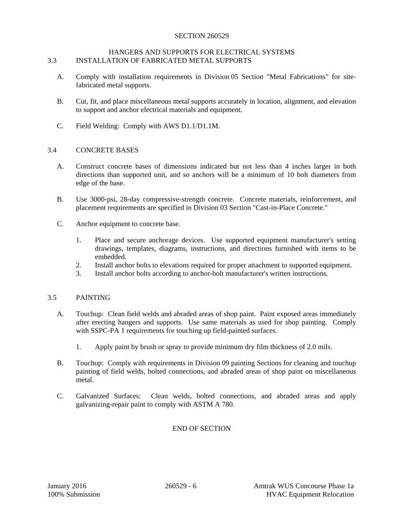
SECTION 260529
HANGERS AND SUPPORTS FOR ELECTRICAL SYSTEMS
January 2016 260529 - 6 Amtrak WUS Concourse Phase 1a 100% Submission HVAC Equipment Relocation
3.3 INSTALLATION OF FABRICATED METAL SUPPORTS
A. Comply with installation requirements in Division 05 Section "Metal Fabrications" for site-fabricated metal supports.
B. Cut, fit, and place miscellaneous metal supports accurately in location, alignment, and elevation to support and anchor electrical materials and equipment.
C. Field Welding: Comply with AWS D1.1/D1.1M.
3.4 CONCRETE BASES
A. Construct concrete bases of dimensions indicated but not less than 4 inches larger in both directions than supported unit, and so anchors will be a minimum of 10 bolt diameters from edge of the base.
B. Use 3000-psi, 28-day compressive-strength concrete. Concrete materials, reinforcement, and placement requirements are specified in Division 03 Section "Cast-in-Place Concrete."
C. Anchor equipment to concrete base.
1. Place and secure anchorage devices. Use supported equipment manufacturer's setting drawings, templates, diagrams, instructions, and directions furnished with items to be embedded.
2. Install anchor bolts to elevations required for proper attachment to supported equipment. 3. Install anchor bolts according to anchor-bolt manufacturer's written instructions.
3.5 PAINTING
A. Touchup: Clean field welds and abraded areas of shop paint. Paint exposed areas immediately after erecting hangers and supports. Use same materials as used for shop painting. Comply with SSPC-PA 1 requirements for touching up field-painted surfaces.
1. Apply paint by brush or spray to provide minimum dry film thickness of 2.0 mils.
B. Touchup: Comply with requirements in Division 09 painting Sections for cleaning and touchup painting of field welds, bolted connections, and abraded areas of shop paint on miscellaneous metal.
C. Galvanized Surfaces: Clean welds, bolted connections, and abraded areas and apply galvanizing-repair paint to comply with ASTM A 780.
END OF SECTION

SECTION 260533
RACEWAYS AND BOXES FOR ELECTRICAL SYSTEMS
January 2016 260533 - 1 Amtrak WUS Concourse Phase 1a100% Submission HVAC Equipment Relocation
PART 1 - GENERAL
1.1 RELATED DOCUMENTS
A. Drawings and general provisions of the Contract, including General and Supplementary Conditions and Division 01 Specification Sections, apply to this Section.
1.2 SUMMARY
A. This Section includes raceways, fittings, boxes, enclosures, and cabinets for electrical wiring.
B. Related Sections include the following:
1. Division 26 Section "Underground Ducts and Raceways for Electrical Systems" for exterior ductbanks, manholes, and underground utility construction.
2. Division 26 Section "Common Work Results for Electrical."
1.3 DEFINITIONS
A. EMT: Electrical metallic tubing.
B. EPDM: Ethylene-propylene-diene terpolymer rubber.
C. FMC: Flexible metal conduit.
D. IMC: Intermediate metal conduit.
E. LFMC: Liquidtight flexible metal conduit.
F. LFNC: Liquidtight flexible nonmetallic conduit.
G. NBR: Acrylonitrile-butadiene rubber.
H. RNC: Rigid nonmetallic conduit.
I. ID: Inner duct.
1.4 SUBMITTALS
A. Product Data: For surface raceways, wireways and fittings, floor boxes, hinged-cover enclosures, and cabinets.
B. Shop Drawings: For the following raceway components. Include plans, elevations, sections, details, and attachments to other work.

SECTION 260533
RACEWAYS AND BOXES FOR ELECTRICAL SYSTEMS
January 2016 260533 - 2 Amtrak WUS Concourse Phase 1a100% Submission HVAC Equipment Relocation
1. Custom enclosures and cabinets. 2. For handholes and boxes for underground wiring, including the following:
a. Duct entry provisions, including locations and duct sizes. b. Frame and cover design. c. Grounding details. d. Dimensioned locations of cable rack inserts, and pulling-in and lifting irons. e. Joint details.
C. Coordination Drawings: Conduit routing plans, drawn to scale, on which the following items are shown and coordinated with each other, based on input from installers of the items involved:
1. Structural members in the paths of conduit groups with common supports. 2. HVAC and plumbing items and architectural features in the paths of conduit groups with
common supports.
D. Qualification Data: For professional engineer and testing agency.
E. Source quality-control test reports.
1.5 QUALITY ASSURANCE
A. Electrical Components, Devices, and Accessories: Listed and labeled as defined in NFPA 70, Article 100, by a testing agency acceptable to authorities having jurisdiction, and marked for intended use.
B. Comply with NFPA 70.
PART 2 - PRODUCTS
2.1 METAL CONDUIT AND TUBING
A. Available Manufacturers: Subject to compliance with requirements, manufacturers offering products that may be incorporated into the Work include, but are not limited to, the following:
1. AFC Cable Systems, Inc. 2. Alflex Inc. 3. Allied Tube & Conduit; a Tyco International Ltd. Co. 4. Anamet Electrical, Inc.; Anaconda Metal Hose. 5. Electri-Flex Co. 6. Manhattan/CDT/Cole-Flex. 7. Maverick Tube Corporation. 8. O-Z Gedney; a unit of General Signal. 9. Wheatland Tube Company.
B. Rigid Steel Conduit: ANSI C80.1.
C. Aluminum Rigid Conduit: ANSI C80.5.

SECTION 260533
RACEWAYS AND BOXES FOR ELECTRICAL SYSTEMS
January 2016 260533 - 3 Amtrak WUS Concourse Phase 1a100% Submission HVAC Equipment Relocation
D. IMC: ANSI C80.6.
E. PVC-Coated Steel Conduit: PVC-coated rigid steel conduit.
1. Comply with NEMA RN 1. 2. Coating Thickness: 0.040 inch, minimum.
F. EMT: ANSI C80.3.
G. FMC: Zinc-coated steel or aluminum.
H. LFMC: Flexible steel conduit with PVC jacket.
I. Fittings for Conduit (Including all Types and Flexible and Liquidtight), EMT, and Cable: NEMA FB 1; listed for type and size raceway with which used, and for application and environment in which installed.
1. Conduit Fittings for Hazardous (Classified) Locations: Comply with UL 886. 2. Fittings for EMT: Steel or die-cast, set-screw or compression type. 3. Coating for Fittings for PVC-Coated Conduit: Minimum thickness, 0.040 inch (1 mm),
with overlapping sleeves protecting threaded joints.
J. Joint Compound for Rigid Steel Conduit or IMC: Listed for use in cable connector assemblies, and compounded for use to lubricate and protect threaded raceway joints from corrosion and enhance their conductivity.
2.2 NONMETALLIC CONDUIT AND TUBING
A. Available Manufacturers: Subject to compliance with requirements, manufacturers offering products that may be incorporated into the Work include, but are not limited to, the following:
B. Manufacturers: Subject to compliance with requirements, provide products by one of the following:
1. AFC Cable Systems, Inc. 2. Anamet Electrical, Inc.; Anaconda Metal Hose. 3. Arnco Corporation. 4. CANTEX Inc. 5. CertainTeed Corp.; Pipe & Plastics Group. 6. Condux International, Inc. 7. ElecSYS, Inc. 8. Electri-Flex Co. 9. Lamson & Sessions; Carlon Electrical Products. 10. Manhattan/CDT/Cole-Flex. 11. RACO; a Hubbell Company. 12. Thomas & Betts Corporation.
C. RNC: NEMA TC 2, Type EPC-40-PVC, unless otherwise indicated.

SECTION 260533
RACEWAYS AND BOXES FOR ELECTRICAL SYSTEMS
January 2016 260533 - 4 Amtrak WUS Concourse Phase 1a100% Submission HVAC Equipment Relocation
D. LFNC: UL 1660.
E. Fittings for ENT and RNC: NEMA TC 3; match to conduit or tubing type and material.
F. Fittings for LFNC: UL 514B.
2.3 OPTICAL FIBER/COMMUNICATIONS CABLE RACEWAY AND FITTINGS
A. Available Manufacturers: Subject to compliance with requirements, manufacturers offering products that may be incorporated into the Work include, but are not limited to, the following:
B. Manufacturers: Subject to compliance with requirements, provide products by one of the following:
1. Arnco Corporation. 2. Endot Industries Inc. 3. IPEX Inc. 4. Lamson & Sessions; Carlon Electrical Products.
C. Description: Inner duct system shall comply with UL 2024; flexible type, approved for riser and general-use installation.
2.4 METAL WIREWAYS
A. Available Manufacturers: Subject to compliance with requirements, manufacturers offering products that may be incorporated into the Work include, but are not limited to, the following:
1. Cooper B-Line, Inc. 2. Hoffman. 3. Square D; Schneider Electric.
B. Description: Sheet metal sized and shaped as indicated, NEMA 250, Type 1, unless otherwise indicated.
C. Fittings and Accessories: Include couplings, offsets, elbows, expansion joints, adapters, hold-down straps, end caps, and other fittings to match and mate with wireways as required for complete system.
D. Wireway Covers: Flanged-and-gasketed type where noted or indicated.
E. Finish: Manufacturer's standard enamel finish.
2.5 SURFACE RACEWAYS
A. Surface Metal Raceways: Galvanized steel with snap-on covers. Manufacturer's standard enamel finish in color selected by Architect.

SECTION 260533
RACEWAYS AND BOXES FOR ELECTRICAL SYSTEMS
January 2016 260533 - 5 Amtrak WUS Concourse Phase 1a100% Submission HVAC Equipment Relocation
1. Available Manufacturers: Subject to compliance with requirements, manufacturers offering products that may be incorporated into the Work include, but are not limited to, the following:
a. Thomas & Betts Corporation. b. Walker Systems, Inc.; Wiremold Company (The). c. Wiremold Company (The); Electrical Sales Division.
2.6 BOXES, ENCLOSURES, AND CABINETS
A. Available Manufacturers: Subject to compliance with requirements, manufacturers offering products that may be incorporated into the Work include, but are not limited to, the following:
1. Cooper Crouse-Hinds; Div. of Cooper Industries, Inc. 2. EGS/Appleton Electric. 3. Erickson Electrical Equipment Company. 4. Hoffman. 5. Hubbell Incorporated; Killark Electric Manufacturing Co. Division. 6. O-Z/Gedney; a unit of General Signal. 7. RACO; a Hubbell Company. 8. Robroy Industries, Inc.; Enclosure Division. 9. Scott Fetzer Co.; Adalet Division. 10. Spring City Electrical Manufacturing Company. 11. Thomas & Betts Corporation. 12. Walker Systems, Inc.; Wiremold Company (The). 13. Woodhead, Daniel Company; Woodhead Industries, Inc. Subsidiary.
B. Sheet Metal Outlet and Device Boxes: NEMA OS 1.
C. Cast-Metal Outlet and Device Boxes: NEMA FB 1, ferrous alloy or aluminum, Type FD, with gasketed cover.
D. Nonmetallic Outlet and Device Boxes: NEMA OS 2.
E. Metal Floor Boxes: Cast or sheet metal, fully adjustable semi-adjustable, rectangular.
F. Small Sheet Metal Pull and Junction Boxes: NEMA OS 1.
G. Cast-Metal Access, Pull, and Junction Boxes: NEMA FB 1, cast aluminum or galvanized, cast iron with gasketed cover.
H. Hinged-Cover Enclosures: NEMA 250, Type 1, with continuous-hinge cover with flush latch, unless otherwise indicated.
1. Metal Enclosures: Steel, finished inside and out with manufacturer's standard enamel.
I. Cabinets:

SECTION 260533
RACEWAYS AND BOXES FOR ELECTRICAL SYSTEMS
January 2016 260533 - 6 Amtrak WUS Concourse Phase 1a100% Submission HVAC Equipment Relocation
1. NEMA 250, Type 1, galvanized-steel box with removable interior panel and removable front, finished inside and out with manufacturer's standard enamel.
2. Hinged door in front cover with flush latch and concealed hinge. 3. Key latch to match panelboards. 4. Metal barriers to separate wiring of different systems and voltage. 5. Accessory feet where required for freestanding equipment.
PART 3 - EXECUTION
3.1 RACEWAY APPLICATION
A. Outdoors: Apply raceway products as specified below, unless otherwise indicated:
1. Exposed Conduit: Rigid steel conduit. 2. Concealed Conduit, Aboveground: Rigid steel conduit, EMT. 3. Underground Conduit: RNC, Type EPC-40-PVC, direct buried. 4. Connection to Vibrating Equipment (Including Transformers and Hydraulic, Pneumatic,
Electric Solenoid, or Motor-Driven Equipment): LFMC or LFNC. 5. Boxes and Enclosures, Aboveground: NEMA 250, Type 3R. 6. Application of Handholes and Boxes for Underground Wiring:
a. Handholes and Pull Boxes in Driveway, Parking Lot, and Off-Roadway Locations, Subject to Occasional, Nondeliberate Loading by Heavy Vehicles: Polymer concrete, Fiberglass enclosures with polymer-concrete frame and cover, Fiberglass-reinforced polyester resin, SCTE 77, Tier 15 structural load rating.
b. Handholes and Pull Boxes in Sidewalk and Similar Applications with a Safety Factor for Nondeliberate Loading by Vehicles: Polymer-concrete units or Heavy-duty fiberglass units with polymer-concrete frame and cover, SCTE 77, Tier 8 structural load rating.
c. Handholes and Pull Boxes Subject to Light-Duty Pedestrian Traffic Only: Fiberglass-reinforced polyester resin, structurally tested according to SCTE 77 with 3000-lbf vertical loading.
B. Comply with the following indoor applications, unless otherwise indicated:
1. Exposed, Not Subject to Physical Damage: EMT. 2. Exposed, Not Subject to Severe Physical Damage: EMT. 3. Exposed and Subject to Severe Physical Damage: Rigid steel conduit. Includes
raceways in the following locations:
a. Loading dock. b. Corridors used for traffic of mechanized carts, forklifts, and pallet-handling units. c. Mechanical rooms.
4. Concealed in Ceilings and Interior Walls and Partitions: [EMT]. 5. Connection to Vibrating Equipment (Including Transformers and Hydraulic, Pneumatic,
Electric Solenoid, or Motor-Driven Equipment): FMC, except use LFMC in damp or wet locations.

SECTION 260533
RACEWAYS AND BOXES FOR ELECTRICAL SYSTEMS
January 2016 260533 - 7 Amtrak WUS Concourse Phase 1a100% Submission HVAC Equipment Relocation
6. Damp or Wet Locations: Rigid steel conduit. 7. Raceways for Optical Fiber or Communications Cable in Spaces Used for Environmental
Air: Plenum-type, optical fiber/communications cable raceway or EMT. 8. Raceways for Optical Fiber or Communications Cable Risers in Vertical Shafts: EMT. 9. Raceways for Concealed General Purpose Distribution of Optical Fiber or
Communications Cable: EMT 10. Boxes and Enclosures: NEMA 250, Type 1, except use NEMA 250, Type 4, stainless
steel in damp or wet locations.
C. Minimum Raceway Size: 3/4-inch trade size.
D. Raceway Fittings: Compatible with raceways and suitable for use and location.
1. Rigid and Intermediate Steel Conduit: Use threaded rigid steel conduit fittings, unless otherwise indicated.
2. PVC Externally Coated, Rigid Steel Conduits: Use only fittings listed for use with that material. Patch and seal all joints, nicks, and scrapes in PVC coating after installing conduits and fittings. Use sealant recommended by fitting manufacturer.
E. Install nonferrous conduit or tubing for circuits operating above 60 Hz. Where aluminum raceways are installed for such circuits and pass through concrete, install in nonmetallic sleeve.
F. Do not install aluminum conduits in contact with concrete.
3.2 INSTALLATION
A. Comply with NECA 1 for installation requirements applicable to products specified in Part 2 except where requirements on Drawings or in this Article are stricter.
B. Keep raceways at least 6 inches (150 mm) away from parallel runs of flues and steam or hot-water pipes. Install horizontal raceway runs above water and steam piping.
C. Complete raceway installation before starting conductor installation.
D. Support raceways as specified in Division 26 Section "Hangers and Supports for Electrical Systems."
E. Arrange stub-ups so curved portions of bends are not visible above the finished slab.
F. Install no more than the equivalent of three 90-degree bends in any conduit run except for communications conduits, for which fewer bends are allowed.
G. Conceal conduit and EMT within finished walls, ceilings, and floors, unless otherwise indicated.
H. Raceways Embedded in Slabs:

SECTION 260533
RACEWAYS AND BOXES FOR ELECTRICAL SYSTEMS
January 2016 260533 - 8 Amtrak WUS Concourse Phase 1a100% Submission HVAC Equipment Relocation
1. Run conduit larger than 1-inch trade size, parallel or at right angles to main reinforcement. Where at right angles to reinforcement, place conduit close to slab support.
2. Arrange raceways to cross building expansion joints at right angles with expansion fittings.
3. Change from ENT to RNC, Type EPC-40-PVC, rigid steel conduit, or IMC before rising above the floor.
I. Threaded Conduit Joints, Exposed to Wet, Damp, Corrosive, or Outdoor Conditions: Apply listed compound to threads of raceway and fittings before making up joints. Follow compound manufacturer's written instructions.
J. Raceway Terminations at Locations Subject to Moisture or Vibration: Use insulating bushings to protect conductors, including conductors smaller than No. 4 AWG.
K. Install pull wires in empty raceways. Use polypropylene or monofilament plastic line with not less than 200-lb tensile strength. Leave at least 12 inches (300 mm) of slack at each end of pull wire.
L. Raceways for Optical Fiber and Communications Cable: Install raceways, metallic and nonmetallic, rigid inner duct and flexible, as follows:
1. 3/4-Inch Trade Size and Smaller: Install raceways in maximum lengths of 100 feet. 2. 1-Inch Trade Size and Larger: Install raceways in maximum lengths of 150 feet. 3. Install with a maximum of two 90-degree bends or equivalent for each length of raceway
unless Drawings show stricter requirements. Separate lengths with pull or junction boxes or terminations at distribution frames or cabinets where necessary to comply with these requirements.
4. Install 1¼" orange or blue inner duct system in raceways for all fiber optic cables.
M. Install raceway sealing fittings at suitable, approved, and accessible locations and fill them with listed sealing compound. For concealed raceways, install each fitting in a flush steel box with a blank cover plate having a finish similar to that of adjacent plates or surfaces. Install raceway sealing fittings at the following points:
1. Where conduits pass from warm to cold locations, such as boundaries of refrigerated spaces.
2. Where otherwise required by NFPA 70.
N. Flexible Conduit Connections: Use maximum of 72 inches of flexible conduit for equipment subject to vibration, noise transmission, or movement; and for transformers and motors.
1. Use LFMC in damp or wet locations subject to severe physical damage. 2. Use LFMC or LFNC in damp or wet locations not subject to severe physical damage.
O. Recessed Boxes in Masonry Walls: Saw-cut opening for box in center of cell of masonry block, and install box flush with surface of wall.
P. Set metal floor boxes level and flush with finished floor surface.

SECTION 260533
RACEWAYS AND BOXES FOR ELECTRICAL SYSTEMS
January 2016 260533 - 9 Amtrak WUS Concourse Phase 1a100% Submission HVAC Equipment Relocation
Q. Set nonmetallic floor boxes level. Trim after installation to fit flush with finished floor surface.
3.3 PROTECTION
A. Provide final protection and maintain conditions that ensure coatings, finishes, and cabinets are without damage or deterioration at time of Substantial Completion.
1. Repair damage to galvanized finishes with zinc-rich paint recommended by manufacturer.
2. Repair damage to PVC or paint finishes with matching touchup coating recommended by manufacturer.
END OF SECTION

SECTION 260553
IDENTIFICATION FOR ELECTRICAL SYSTEMS
January 2016 260553 - 1 Amtrak WUS Concourse Phase 1a100% Submission HVAC Equipment Relocation
PART 1 - GENERAL
1.1 RELATED DOCUMENTS
A. Drawings and general provisions of the Contract, including General and Supplementary Conditions and Division 01 Specification Sections, apply to this Section.
1.2 SUMMARY
A. This Section includes the following:
1. Identification for raceway and metal-clad cable. 2. Identification for power conductors and communication and control cable. 3. Underground-line warning tape. 4. Warning labels and signs, including arc flash labeling. 5. Instruction signs. 6. Equipment identification labels. 7. Miscellaneous identification products.
1.3 SUBMITTALS
A. Product Data: For each electrical identification product indicated.
B. Identification Schedule: An index of nomenclature of electrical cables, equipment and system components used in identification signs and labels.
C. Samples: For each type of label and sign to illustrate size, colors, lettering style, mounting provisions, and graphic features of identification products.
1.4 QUALITY ASSURANCE
A. Comply with ANSI A13.1 and ANSI C2 and IEEE C2.
B. Comply with NFPA 70.
C. Comply with 29 CFR 1910.144 and 29 CFR 1910.145.
D. Comply with NFPA 70E.
E. Comply with ANSI Z535, arc flash labels.
F. Comply with OSHA requirements for electrical labeling.
G. Adhesive-attached labeling materials, including label stocks, laminating adhesives, and inks used by label printers, shall comply with UL 969.

SECTION 260553
IDENTIFICATION FOR ELECTRICAL SYSTEMS
January 2016 260553 - 2 Amtrak WUS Concourse Phase 1a100% Submission HVAC Equipment Relocation
1.5 COORDINATION
A. Coordinate identification names, abbreviations, colors, and other features with requirements in other sections requiring identification applications, Drawings, Shop Drawings, manufacturer's wiring diagrams, and the Operation and Maintenance Manual, and with those required by codes, standards, and 29 CFR 1910.145. Use consistent designations throughout Project.
B. Coordinate installation of identifying devices with completion of covering and painting of surfaces where devices are to be applied.
C. Coordinate installation of identifying devices with location of access panels and doors.
D. Install identifying devices before installing acoustical ceilings and similar concealment.
PART 2 - PRODUCTS
2.1 RACEWAY AND METAL-CLAD CABLE IDENTIFICATION MATERIALS
A. Comply with ANSI A13.1 for minimum size of letters for legend and for minimum length of color field for each raceway and cable size.
B. Colors for Raceways Carrying Circuits at 600 V or Less:
1. Black letters on an orange field 2. Legend: Indicate voltage and system or service type.
C. Self-Adhesive Vinyl Labels for raceways carrying circuits 600V or less: Preprinted, flexible label laminated with a clear, weather- and chemical-resistant coating and matching wraparound adhesive tape for securing ends of legend label.
D. Snap-Around Labels for raceways carrying circuits 600V or less: Slit, pretensioned, flexible, preprinted, color-coded acrylic sleeves, with diameter sized to suit diameter of raceway or cable it identifies and to stay in place by gripping action.
E. Snap-Around, Color-Coding Bands for raceways carrying circuits 600V or less: Slit, pretensioned, flexible, solid-colored acrylic sleeves, 2 inches (50 mm) long, with diameter sized to suit diameter of raceway or cable it identifies and to stay in place by gripping action.
F. Write-On Tags: Polyester tag, [0.015 inch (0.38 mm)] thick, with corrosion-resistant grommet and cable tie for attachment to conductor or cable.
1. Marker for Tags: Permanent, waterproof, black ink marker recommended by tag manufacturer.
2. Marker for Tags: Machine-printed, permanent, waterproof, black ink marker recommended by printer manufacturer.

SECTION 260553
IDENTIFICATION FOR ELECTRICAL SYSTEMS
January 2016 260553 - 3 Amtrak WUS Concourse Phase 1a100% Submission HVAC Equipment Relocation
2.2 METAL-CLAD CABLE IDENTIFICATION MATERIALS
A. Comply with ANSI A13.1 for minimum size of letters for legend and for minimum length of color field for each raceway and cable size.
B. Colors for Raceways Carrying Circuits at 600 V and Less:
1. Black letters on an orange field. 2. Legend: Indicate voltage and system or service type.
C. Self-Adhesive Vinyl Labels: Preprinted, flexible label laminated with a clear, weather- and chemical-resistant coating and matching wraparound adhesive tape for securing ends of legend label.
2.3 POWER AND CONTROL CABLE IDENTIFICATION MATERIALS
A. Comply with ANSI A13.1 for minimum size of letters for legend and for minimum length of color field for each raceway and cable size.
B. Self-Adhesive Vinyl Labels: Preprinted, flexible label laminated with a clear, weather- and chemical-resistant coating and matching wraparound adhesive tape for securing ends of legend label.
C. Write-On Tags: Polyester tag, 0.015 inch thick, with corrosion-resistant grommet and cable tie for attachment to conductor or cable.
1. Marker for Tags: Permanent, waterproof, black ink marker recommended by tag manufacturer.
2. Marker for Tags: Machine-printed, permanent, waterproof, black ink marker recommended by printer manufacturer.
D. Snap-Around Labels: Slit, pretensioned, flexible, preprinted, color-coded acrylic sleeve, with diameter sized to suit diameter of raceway or cable it identifies and to stay in place by gripping action.
E. Snap-Around, Color-Coding Bands: Slit, pretensioned, flexible, solid-colored acrylic sleeve, 2 inches (50 mm) long, with diameter sized to suit diameter of raceway or cable it identifies and to stay in place by gripping action.
2.4 CONDUCTOR IDENTIFICATION MATERIALS
A. Color-Coding Conductor Tape: Colored, self-adhesive vinyl tape not less than 3 mils thick by 1 to 2 inches wide.
B. Self-Adhesive Vinyl Labels: Preprinted, flexible label laminated with a clear, weather- and chemical-resistant coating and matching wraparound adhesive tape for securing ends of legend label.

SECTION 260553
IDENTIFICATION FOR ELECTRICAL SYSTEMS
January 2016 260553 - 4 Amtrak WUS Concourse Phase 1a100% Submission HVAC Equipment Relocation
C. Snap-Around Labels: Slit, pretensioned, flexible, preprinted, color-coded acrylic sleeve, with diameter sized to suit diameter of raceway or cable it identifies and to stay in place by gripping action.
D. Snap-Around, Color-Coding Bands: Slit, pretensioned, flexible, solid-colored acrylic sleeve, 2 inches long, with diameter sized to suit diameter of raceway or cable it identifies and to stay in place by gripping action.
E. Marker Tapes: Vinyl or vinyl-cloth, self-adhesive wraparound type, with circuit identification legend machine printed by thermal transfer or equivalent process.
F. Write-On Tags: Polyester tag, 0.015 inch thick, with corrosion-resistant grommet and cable tie for attachment to conductor or cable.
1. Marker for Tags: Permanent, waterproof, black ink marker recommended by tag manufacturer.
2. Marker for Tags: Machine-printed, permanent, waterproof, black ink marker recommended by printer manufacturer.
2.5 CONDUCTOR AND COMMUNICATION- AND CONTROL-CABLE IDENTIFICATION MATERIALS
A. Color-Coding Conductor Tape: Colored, self-adhesive vinyl tape not less than 3 mils (0.08 mm) thick by 1 to 2 inches wide.
B. Marker Tapes: Vinyl or vinyl-cloth, self-adhesive wraparound type, with circuit identification legend machine printed by thermal transfer or equivalent process.
C. Write-On Tags: Polyester tag, 0.015 inch thick, with corrosion-resistant grommet and polyester or nylon tie for attachment to conductor or cable.
1. Marker for Tags: Permanent, waterproof, black ink marker recommended by tag manufacturer.
2.6 WARNING LABELS AND SIGNS
A. Comply with NFPA 70, NFPA 70E and 29 CFR 1910.145.
B. Self-Adhesive Warning Labels: Factory printed, multicolor, pressure-sensitive adhesive labels, configured for display on front cover, door, or other access to equipment, unless otherwise indicated.
C. Baked-Enamel Warning Signs: 1. Preprinted aluminum signs, punched or drilled for fasteners, with colors, legend, and size
required for application. 2. 1/4-inch grommets in corners for mounting. 3. Nominal size, 7 by 10 inches.

SECTION 260553
IDENTIFICATION FOR ELECTRICAL SYSTEMS
January 2016 260553 - 5 Amtrak WUS Concourse Phase 1a100% Submission HVAC Equipment Relocation
D. Metal-Backed, Butyrate Warning Signs: 1. Weather-resistant, nonfading, preprinted, cellulose-acetate butyrate signs with 0.0396-
inch galvanized-steel backing; and with colors, legend, and size required for application. 2. 1/4-inch grommets in corners for mounting. 3. Nominal size, 10 by 14 inches.
E. Warning label and sign shall include, but are not limited to, the following legends:
1. Multiple Power Source Warning: "DANGER - ELECTRICAL SHOCK HAZARD - EQUIPMENT HAS MULTIPLE POWER SOURCES."
2. Workspace Clearance Warning: "WARNING - OSHA REGULATION - AREA IN FRONT OF ELECTRICAL EQUIPMENT MUST BE KEPT CLEAR FOR 36 INCHES (915 MM)."
2.7 INSTRUCTION SIGNS
A. Engraved, laminated acrylic or melamine plastic, minimum 1/16 inch thick for signs up to 20 sq. in. and 1/8 inch thick for larger sizes.
1. Engraved legend with black letters on white face. 2. Punched or drilled for mechanical fasteners. 3. Framed with mitered acrylic molding and arranged for attachment at applicable
equipment.
B. Adhesive Film Label: Machine printed, in black, by thermal transfer or equivalent process. Minimum letter height shall be 3/8 inch.
C. Adhesive Film Label with Clear Protective Overlay: Machine printed, in black, by thermal transfer or equivalent process. Minimum letter height shall be 3/8 inch (10 mm). Overlay shall provide a weatherproof and UV-resistant seal for label.
2.8 EQUIPMENT IDENTIFICATION LABELS
A. Adhesive Film Label: Machine printed, in black, by thermal transfer or equivalent process. Minimum letter height shall be 3/8 inch.
B. Adhesive Film Label with Clear Protective Overlay: Machine printed, in black, by thermal transfer or equivalent process. Minimum letter height shall be 3/8 inch. Overlay shall provide a weatherproof and ultraviolet-resistant seal for label.
C. Self-Adhesive, Engraved, Laminated Acrylic or Melamine Label: Adhesive backed, with white letters on a dark-gray background. Minimum letter height shall be 3/8 inch.
D. Engraved, Laminated Acrylic or Melamine Label: Punched or drilled for screw mounting. White letters on a dark-gray background. Minimum letter height shall be 3/8 inch.
E. Stenciled Legend: In nonfading, waterproof, black ink or paint. Minimum letter height shall be 1 inch.

SECTION 260553
IDENTIFICATION FOR ELECTRICAL SYSTEMS
January 2016 260553 - 6 Amtrak WUS Concourse Phase 1a100% Submission HVAC Equipment Relocation
2.9 CABLE TIES
A. General-Purpose Cable Ties: Fungus inert, self-extinguishing, one piece, self-locking, Type 6/6 nylon.
1. Minimum Width: 3/16 inch. 2. Tensile Strength at 73 deg F, According to ASTM D 638: 12,000 psi. 3. Temperature Range: Minus 40 to plus 185 deg F. 4. Color: Black except where used for color-coding.
B. UV-Stabilized Cable Ties: Fungus inert, designed for continuous exposure to exterior sunlight, self-extinguishing, one piece, self-locking, Type 6/6 nylon.
1. Minimum Width: 3/16 inch. 2. Tensile Strength at 73 deg F (23 deg C), According to ASTM D 638: 12,000 psi. 3. Temperature Range: Minus 40 to plus 185 deg F. 4. Color: Black.
C. Plenum-Rated Cable Ties: Self-extinguishing, UV stabilized, one piece, self-locking.
1. Minimum Width: 3/16 inch. 2. Tensile Strength at 73 deg F (23 deg C), According to ASTM D 638: 7000 psi. 3. UL 94 Flame Rating: 94V-0. 4. Temperature Range: Minus 50 to plus 284 deg F. 5. Color: Black.
2.10 MISCELLANEOUS IDENTIFICATION PRODUCTS
A. Cable Ties: Fungus-inert, self-extinguishing, 1-piece, self-locking, Type 6/6 nylon cable ties.
1. Minimum Width: 3/16 inch. 2. Tensile Strength: 50 lb, minimum. 3. Temperature Range: Minus 40 to plus 185 deg F. 4. Color: Black, except where used for color-coding.
B. Paint: Paint materials and application requirements are specified in Division 09 painting Sections.
1. Exterior Ferrous Metal:
a. Semi-gloss Alkyd-Enamel Finish: One finish coat over a primer.
1) Primer: Exterior ferrous-metal primer. 2) Finish Coats: Exterior semigloss alkyd enamel.
2. Interior Ferrous Metal:
a. Semi-gloss Acrylic-Enamel Finish: One finish coat over a primer.
1) Primer: Interior ferrous-metal primer.

SECTION 260553
IDENTIFICATION FOR ELECTRICAL SYSTEMS
January 2016 260553 - 7 Amtrak WUS Concourse Phase 1a100% Submission HVAC Equipment Relocation
2) Finish Coats: Interior semigloss acrylic enamel.
3. Interior Zinc-Coated Metal (except Raceways):
a. Clean/pickle bare metal with white vinegar. b. Semi-gloss Acrylic-Enamel Finish: One finish coat over a primer.
1) Primer: Interior zinc-coated metal primer. 2) Finish Coats: Interior semigloss acrylic enamel.
C. Fasteners for Labels and Signs: Self-tapping, stainless-steel screws or stainless-steel machine screws with nuts and flat and lock washers.
PART 3 - EXECUTION
3.1 APPLICATION
A. Accessible Raceways and Metal-Clad Cables, 600 V or Less, for Service, Feeder, and Branch Circuits More Than 30 A: Identify with field applied paint on each box cover plate to identify system cabling contained with as follows: 1. Blue for 208/120 volt normal power circuits. 2. Green for 208/120 volt “essential” power circuit. 3. Orange for 480/277 volt normal power circuits. 4. Yellow for 480/277 volt “life safety” lighting circuits.
B. Accessible Raceways and Cables of Auxiliary Systems: Identify the following systems with color-coded, self-adhesive vinyl tape applied in bands or snap-around, color-coding bands:
1. Fire Alarm System: Red. 2. Fire-Suppression Supervisory and Control System: Red and yellow. 3. Combined Fire Alarm and Security System: Red and blue. 4. Security System: Blue and yellow. 5. Mechanical and Electrical Supervisory System: Green and blue. 6. Telecommunication System: Green and yellow. 7. Control Wiring: Green and red.
C. Power-Circuit Conductor Identification: For secondary conductors No. 1/0 AWG and larger in vaults, pull and junction boxes, manholes, and handholes use color-coding conductor tape, marker tape or write-on tags. Identify source and circuit number of each set of conductors. For single conductor cables, identify phase in addition to the above.
D. Branch-Circuit Conductor Identification: Where there are conductors for more than three branch circuits in same junction or pull box, use color-coding conductor tape, marker tape, or write. Identify each ungrounded conductor according to source and circuit number.
E. Locations of Underground Lines: Identify with underground-line warning tape for power, lighting, communication, and control wiring and optical fiber cable. Install underground-line warning tape for both direct-buried cables and cables in raceway.

SECTION 260553
IDENTIFICATION FOR ELECTRICAL SYSTEMS
January 2016 260553 - 8 Amtrak WUS Concourse Phase 1a100% Submission HVAC Equipment Relocation
F. Warning Labels for Indoor Cabinets, Boxes, and Enclosures for Power and Lighting: Comply with 29 CFR 1910.145 and apply self-adhesive warning labels, baked-enamel warning signs, or metal-backed, butyrate warning signs. Identify system voltage with black letters on an orange background. Apply to exterior of door, cover, or other access.
1. Equipment with Multiple Power or Control Sources: Apply to door or cover of equipment including, but not limited to, the following:
a. Power transfer switches. b. Controls with external control power connections.
2. Equipment Requiring Workspace Clearance According to NFPA 70: Unless otherwise indicated, apply to door or cover of equipment but not on flush panelboards and similar equipment in finished spaces.
G. Instruction Signs:
1. Operating Instructions: Install instruction signs to facilitate proper operation and maintenance of electrical systems and items to which they connect. Install instruction signs with approved legend where instructions are needed for system or equipment operation.
2. Emergency Operating Instructions: Install instruction signs with white legend on a red background with minimum 3/8-inch- high letters for emergency instructions at equipment used for power transfer or load shedding.
H. Equipment Identification Labels: On each unit of equipment, install unique designation label that is consistent with wiring diagrams, schedules, and Operation and Maintenance Manual. Apply labels to disconnect switches and protection equipment, central or master units, control panels, control stations, terminal cabinets, and racks of each system. Systems include power, lighting, control, communication, signal, monitoring, and alarm systems unless equipment is provided with its own identification.
1. Labeling Instructions:
a. Indoor and Outdoor Equipment: Screwed-on engraved white laminated plastic sheet with minimum 3/8 inch to 3/4 inch black lettering for normal systems and red laminated plastic sheet with lettering for energy systems.
b. Elevated Components: Increase sizes of labels and letters to those appropriate for viewing from the floor.
2. Equipment to Be Labeled:
a. Panelboards, electrical cabinets, and enclosures. b. Access doors and panels for concealed electrical items. c. Electrical switchgear and switchboards. d. Transformers. e. Electrical substations. f. Emergency system boxes and enclosures. g. Motor-control centers. h. Disconnect switches.

SECTION 260553
IDENTIFICATION FOR ELECTRICAL SYSTEMS
January 2016 260553 - 9 Amtrak WUS Concourse Phase 1a100% Submission HVAC Equipment Relocation
i. Enclosed circuit breakers. j. Motor starters. k. Push-button stations. l. Power transfer equipment. m. Contactors. n. Remote-controlled switches, dimmer modules, and control devices. o. Voice and data cable terminal equipment. p. Master clock and program equipment. q. Intercommunication and call system master and staff stations.
3.2 INSTALLATION
A. Verify identity of each item before installing identification products.
B. Location: Install identification materials and devices at locations for most convenient viewing without interference with operation and maintenance of equipment.
C. Apply identification devices to surfaces that require finish after completing finish work.
D. Self-Adhesive Identification Products: Clean surfaces before application, using materials and methods recommended by manufacturer of identification device.
E. Attach nonadhesive signs and plastic labels that are not self-adhesive type with mechanical fasteners appropriate to the location and substrate.
F. System Identification Color Banding for Raceways and Cables: Each color band shall completely encircle cable or conduit. Place adjacent bands of two-color markings in contact, side by side. Locate bands at changes in direction, at penetrations of walls and floors, at 50-foot maximum intervals in straight runs, and at 25-foot maximum intervals in congested areas.
G. Aluminum Wraparound Marker Labels and Metal Tags: Secure tight to surface of conductor or cable at a location with high visibility and accessibility.
H. Cable Ties: For attaching tags. Use general-purpose type, except as listed below:
1. Outdoors: UV-stabilized nylon. 2. In Spaces Handling Environmental Air: Plenum rated.
I. Underground-Line Warning Tape: During backfilling of trenches install continuous underground-line warning tape directly above line at 6 to 8 inches below finished grade. Use multiple tapes where width of multiple lines installed in a common trench or concrete envelope exceeds 16 inches overall.
J. Painted Identification: Comply with requirements in Division 09 painting Sections for surface preparation and paint application.

SECTION 260553
IDENTIFICATION FOR ELECTRICAL SYSTEMS
January 2016 260553 - 10 Amtrak WUS Concourse Phase 1a100% Submission HVAC Equipment Relocation
3.3 IDENTIFICATION SCHEDULE
A. Accessible Raceways and Metal-Clad Cables, 600 V or Less, for Service, Feeder, and Branch Circuits More Than 30 A, and 120 V to ground: Identify with self-adhesive vinyl label, self-adhesive vinyl tape applied in bands. Install labels at 10-foot maximum intervals.
B. Accessible Raceways and Cables within Buildings: Identify the covers of each junction and pull box of the following systems with self-adhesive vinyl labels with the wiring system legend and system voltage. System legends shall be as follows:
1. Emergency Power. 2. Power. 3. UPS. 4. Lighting
C. Power-Circuit Conductor Identification, 600 V or Less: For conductors in vaults, pull and junction boxes, manholes, and handholes, use color-coding conductor tape to identify the phase.
1. Color-Coding for Phase and Voltage Level] Identification, 600 V or Less: Use colors listed below for ungrounded feeder and branch-circuit conductors.
a. Color shall be factory applied or field applied for sizes larger than No. 8 AWG, if authorities having jurisdiction permit.
b. Colors for 208/120-V Circuits:
1) Phase A: Black. 2) Phase B: Red. 3) Phase C: Blue.
c. Colors for 480/277-V Circuits:
1) Phase A: Brown. 2) Phase B: Orange. 3) Phase C: Yellow.
d. Field-Applied, Color-Coding Conductor Tape: Apply in half-lapped turns for a minimum distance of 6 inches from terminal points and in boxes where splices or taps are made. Apply last two turns of tape with no tension to prevent possible unwinding. Locate bands to avoid obscuring factory cable markings.
D. Underground-Line Warning Tape: During backfilling of trenches install continuous underground-line warning tape directly above line at 10 to 12 inches below finished grade.
E. Painted Identification: Prepare surface and apply paint according to Division 09 painting Sections.
F. Install instructional sign including the color-code for grounded and ungrounded conductors using adhesive-film-type labels.

SECTION 260553
IDENTIFICATION FOR ELECTRICAL SYSTEMS
January 2016 260553 - 11 Amtrak WUS Concourse Phase 1a100% Submission HVAC Equipment Relocation
G. Auxiliary Electrical Systems Conductor Identification: Identify field-installed alarm, control, and signal connections.
1. Identify conductors, cables, and terminals in enclosures and at junctions, terminals, and pull points. Identify by system and circuit designation.
2. Use system of marker tape designations that is uniform and consistent with system used by manufacturer for factory-installed connections.
3. Coordinate identification with Project Drawings, manufacturer's wiring diagrams, and the Operation and Maintenance Manual.
H. Workspace Indication: Install floor marking tape to show working clearances in the direction of access to live parts. Workspace shall be as required by NFPA 70 and 29 CFR 1926.403 unless otherwise indicated. Do not install at flush-mounted panelboards and similar equipment in finished spaces.
I. Warning Labels for Indoor Cabinets, Boxes, and Enclosures for Power and Lighting: Self-adhesive warning labels, Baked-enamel warning signs, or Metal-backed, butyrate warning signs.
1. Comply with 29 CFR 1910.145. 2. Identify system voltage with black letters on an orange background. 3. Apply to exterior of door, cover, or other access. 4. For equipment with multiple power or control sources, apply to door or cover of
equipment including, but not limited to, the following:
a. Power transfer switches.
J. Operating Instruction Signs: Install instruction signs to facilitate proper operation and maintenance of electrical systems and items to which they connect. Install instruction signs with approved legend where instructions are needed for system or equipment operation.
K. Equipment Identification Labels: On each unit of equipment, install unique designation label that is consistent with wiring diagrams, schedules, and the Operation and Maintenance Manual. Apply labels to disconnect switches and protection equipment, central or master units, control panels, control stations, terminal cabinets, and racks of each system. Systems include power, lighting, control, communication, signal, monitoring, and alarm systems unless equipment is provided with its own identification.
1. Labeling Instructions:
a. Indoor Equipment: Adhesive film label, Self-adhesive, engraved, laminated acrylic or melamine label or Engraved, laminated acrylic or melamine label. Unless otherwise indicated, provide a single line of text with 1/2-inch- high letters on 1-1/2-inch- high label; where two lines of text are required, use labels 2 inches high.
b. Outdoor Equipment: Engraved, laminated acrylic or melamine label with Stenciled legend 4 inches high.
c. Elevated Components: Increase sizes of labels and letters to those appropriate for viewing from the floor.

SECTION 260553
IDENTIFICATION FOR ELECTRICAL SYSTEMS
January 2016 260553 - 12 Amtrak WUS Concourse Phase 1a100% Submission HVAC Equipment Relocation
d. Unless provided with self-adhesive means of attachment, fasten labels with appropriate mechanical fasteners that do not change the NEMA or NRTL rating of the enclosure.
2. Equipment to Be Labeled:
a. Panelboards: Typewritten directory of circuits in the location provided by panelboard manufacturer. Panelboard identification shall be self-adhesive, engraved, laminated acrylic or melamine label.
b. Enclosures and electrical cabinets. c. Access doors and panels for concealed electrical items. d. Switchgear. e. Switchboards. f. Transformers: Label that includes tag designation shown on Drawings for the
transformer, feeder, and panelboards or equipment supplied by the secondary. g. Substations. h. Emergency system boxes and enclosures. i. Motor-control centers. j. Enclosed switches. k. Enclosed circuit breakers. l. Enclosed controllers. m. Variable-speed controllers. n. Push-button stations. o. Power transfer equipment. p. Contactors. q. Remote-controlled switches, dimmer modules, and control devices. r. Monitoring and control equipment.
END OF SECTION

SECTION 262200
LOW-VOLTAGE TRANSFORMERS
January 2016 262200 - 1 Amtrak WUS Concourse Phase 1100% Submission HVAC Equipment Relocation
PART 1 - GENERAL
1.1 RELATED DOCUMENTS
A. Drawings and general provisions of the Contract, including General and Supplementary Conditions and Division 01 Specification Sections, apply to this Section.
B. Related Sections include the following:
1. Division 26 Section "Common Work Results for Electrical." 2. Division 26 Section "Low-Voltage Electrical Power Conductors and Cables." 3. Division 26 Section "Grounding and Bonding for Electrical Systems." 4. Division 26 Section "Overcurrent Protective Device Coordination Study."
1.2 SUMMARY
A. This Section includes the following types of dry-type transformers rated 600 V and less:
1. Distribution transformers.
1.3 SUBMITTALS
A. Product Data: Include rated nameplate data, capacities, weights, dimensions, minimum clearances, installed devices and features, and performance for each type and size of transformer indicated.
B. Shop Drawings: Detail equipment assemblies and indicate dimensions, weights, loads, required clearances, method of field assembly, components, and location and size of each field connection.
1. Wiring Diagrams: Power, signal, and control wiring.
C. Qualification Data: For testing agency.
D. Source quality-control test reports.
E. Field quality-control test reports.
F. Operation and Maintenance Data: For transformers to include in emergency, operation, and maintenance manuals.
1.4 QUALITY ASSURANCE
A. Source Limitations: Obtain each transformer type through one source from a single manufacturer.

SECTION 262200
LOW-VOLTAGE TRANSFORMERS
January 2016 262200 - 2 Amtrak WUS Concourse Phase 1100% Submission HVAC Equipment Relocation
B. Electrical Components, Devices, and Accessories: Listed and labeled as defined in NFPA 70, Article 100, by a testing agency acceptable to authorities having jurisdiction, and marked for intended use.
C. Comply with IEEE C57.12.91, "Test Code for Dry-Type Distribution and Power Transformers."
1.5 DELIVERY, STORAGE, AND HANDLING
A. Temporary Heating: Apply temporary heat according to manufacturer's written instructions within the enclosure of each ventilated-type unit, throughout periods during which equipment is not energized and when transformer is not in a space that is continuously under normal control of temperature and humidity.
1.6 COORDINATION
A. Coordinate size and location of concrete bases with actual transformer provided. Cast anchor-bolt inserts into bases. Concrete, reinforcement, and formwork requirements are specified in Division 03.
B. Coordinate installation of wall-mounting and structure-hanging supports with actual transformer provided.
PART 2 - PRODUCTS
2.1 MANUFACTURERS
A. Available Manufacturers: Subject to compliance with requirements, manufacturers offering products that may be incorporated into the Work include, but are not limited to, the following:
1. Eaton Electrical Inc.; Cutler-Hammer Products. 2. General Electric Company. 3. Hammond Co.; Matra Electric, Inc. 4. Magnetek Power Electronics Group. 5. Siemens Energy & Automation, Inc. 6. Square D; Schneider Electric. 7. Cooper Power System.
2.2 GENERAL TRANSFORMER REQUIREMENTS
A. Description: Factory-assembled and -tested, air-cooled units for 60-Hz service.
B. Cores: Grain-oriented, non-aging silicon steel.
C. Coils: Continuous windings without splices except for taps.
1. Internal Coil Connections: Brazed or pressure type.

SECTION 262200
LOW-VOLTAGE TRANSFORMERS
January 2016 262200 - 3 Amtrak WUS Concourse Phase 1100% Submission HVAC Equipment Relocation
2. Coil Material: Copper
2.3 DISTRIBUTION TRANSFORMERS
A. Comply with NEMA ST 20, and list and label as complying with UL 1561.
B. Cores: One leg per phase.
C. Enclosure: Ventilated, NEMA 250, Type 2.
1. Core and coil shall be encapsulated within resin compound, sealing out moisture and air.
D. Transformer Enclosure Finish: Comply with NEMA 250.
1. Finish Color: ANSI 49 gray or ANSI 61 gray.
E. Taps for Transformers Smaller than 3 kVA: One 5 percent tap above normal full capacity.
F. Taps for Transformers 7.5 to 24 kVA: One 5 percent tap above and one 5 percent tap below normal full capacity.
G. Taps for Transformers 25 kVA and Larger: Two 2.5 percent taps above and two 2.5 percent taps below normal full capacity.
H. Insulation Class: 220 deg C, UL-component-recognized insulation system with a maximum of 150 deg C rise above 40 deg C ambient temperature.
I. Energy Efficiency for Transformers Rated 15 kVA and Larger:
1. Complying with NEMA TP 1, Class 1 efficiency levels. 2. Tested according to NEMA TP 2.
J. Electrostatic Shielding: Each winding shall have an independent, single, full-width copper electrostatic shield arranged to minimize interwinding capacitance.
1. Arrange coil leads and terminal strips to minimize capacitive coupling between input and output terminals.
2. Include special terminal for grounding the shield. 3. Shield Effectiveness:
a. Capacitance between Primary and Secondary Windings: Not to exceed 33 picofarads over a frequency range of 20 Hz to 1 MHz.
b. Common-Mode Noise Attenuation: Minimum of minus 120 dBA at 0.5 to 1.5 kHz; minimum of minus 65 dBA at 1.5 to 100 kHz.
c. Normal-Mode Noise Attenuation: Minimum of minus 52 dBA at 1.5 to 10 kHz.
K. Wall Brackets: Manufacturer's standard brackets.
L. Low-Sound-Level Requirements: Minimum of 3 dBA less than NEMA ST 20 standard sound levels when factory tested according to IEEE C57.12.91.

SECTION 262200
LOW-VOLTAGE TRANSFORMERS
January 2016 262200 - 4 Amtrak WUS Concourse Phase 1100% Submission HVAC Equipment Relocation
2.4 IDENTIFICATION DEVICES
A. Nameplates: Engraved, laminated-plastic or metal nameplate for each distribution transformer, mounted with corrosion-resistant screws. Nameplates and label products are specified in Division 26 Section "Identification for Electrical Systems."
2.5 SOURCE QUALITY CONTROL
A. Test and inspect transformers according to IEEE C57.12.91.
B. Factory Sound-Level Tests: Conduct sound-level tests on equipment for this Project.
PART 3 - EXECUTION
3.1 EXAMINATION
A. Examine conditions for compliance with enclosure- and ambient-temperature requirements for each transformer.
B. Verify that field measurements are as needed to maintain working clearances required by NFPA 70 and manufacturer's written instructions.
C. Examine walls, floors, roofs, and concrete bases for suitable mounting conditions where transformers will be installed.
D. Verify that ground connections are in place and requirements in Division 26 Section "Grounding and Bonding for Electrical Systems" have been met. Maximum ground resistance shall be 5 ohms at location of transformer.
E. Proceed with installation only after unsatisfactory conditions have been corrected.
3.2 INSTALLATION
A. Install wall-mounting transformers level and plumb with wall brackets fabricated by transformer manufacturer.
B. Construct concrete bases and anchor floor-mounting transformers according to manufacturer's written instructions
3.3 CONNECTIONS
A. Ground equipment according to Division 26 Section "Grounding and Bonding for Electrical Systems."
B. Connect wiring according to Division 26 Section "Low-Voltage Electrical Power Conductors and Cables."

SECTION 262200
LOW-VOLTAGE TRANSFORMERS
January 2016 262200 - 5 Amtrak WUS Concourse Phase 1100% Submission HVAC Equipment Relocation
C. Provide 200% neutral for all k-rated transformers.
3.4 FIELD QUALITY CONTROL
A. Tests and Inspections:
1. Perform each visual and mechanical inspection and electrical test stated in NETA Acceptance Testing Specification. Certify compliance with test parameters.
B. Remove and replace units that do not pass tests or inspections and retest as specified above.
3.5 CLEANING
A. Vacuum dirt and debris; do not use compressed air to assist in cleaning.
END OF SECTION

SECTION 262413
SWITCHBOARDS
January 2016 262413 - 1 Amtrak WUS Concourse Phase 1a100% Submission HVAC Equipment Relocation
PART 1 - GENERAL
1.1 RELATED DOCUMENTS
A. Drawings and general provisions of the Contract, including General and Supplementary Conditions and Division 01 Specification Sections, apply to this Section.
1.2 SUMMARY
A. Section Includes:
1. Service and distribution switchboards rated 600 V and less. 2. Instrumentation. 3. Control power. 4. Accessory components and features. 5. Identification. 6. Mimic bus.
B. Related Sections include the following:
1. Division 26 Section "Low-Voltage Electrical Power Conductors and Cables." 2. Division 26 Section "Grounding and Bonding for Electrical Systems." 3. Division 26 Section "Vibration and Seismic Controls for Electrical Systems." 4. Division 26 Section "Identification for Electrical Systems." 5. Division 26 Section "Enclosed Switches and Circuit Breakers."
1.3 SUBMITTALS
A. Product Data: For each type of switchboard, overcurrent protective device, transient voltage suppression device, ground-fault protector, accessory, and component indicated. Include dimensions and manufacturers' technical data on features, performance, electrical characteristics, ratings, accessories, and finishes.
B. Shop Drawings: For each switchboard and related equipment.
1. Include dimensioned plans, elevations, sections, and details, including required clearances and service space around equipment. Show tabulations of installed devices, equipment features, and ratings.
2. Detail enclosure types for types other than NEMA 250, Type 1. 3. Detail bus configuration, current, and voltage ratings. 4. Detail short-circuit current rating of switchboards and overcurrent protective devices. 5. Include descriptive documentation of optional barriers specified for electrical insulation
and isolation. 6. Detail utility company's metering provisions with indication of approval by utility
company.

SECTION 262413
SWITCHBOARDS
January 2016 262413 - 2 Amtrak WUS Concourse Phase 1a100% Submission HVAC Equipment Relocation
7. Detail features, characteristics, ratings, and factory settings of individual overcurrent protective devices and auxiliary components.
8. Include time-current coordination curves for each type and rating of overcurrent protective device included in switchboards. Submit on translucent log-log graft paper; include selectable ranges for each type of overcurrent protective device.
9. Include diagram and details of proposed mimic bus. 10. Include schematic and wiring diagrams for power, signal, and control wiring.
C. Samples: Representative portion of mimic bus with specified material and finish, for color selection.
D. Field Quality-Control Reports:
1. Test procedures used. 2. Test results that comply with requirements. 3. Results of failed tests and corrective action taken to achieve test results that comply with
requirements.
E. Operation and Maintenance Data: For switchboards and components to include in emergency, operation, and maintenance manuals. In addition to items specified in Division 01 Section "Operation and Maintenance Data," include the following:
1. Routine maintenance requirements for switchboards and all installed components. 2. Manufacturer's written instructions for testing and adjusting overcurrent protective
devices. 3. Time-current coordination curves for each type and rating of overcurrent protective
device included in switchboards. Submit on translucent log-log graft paper; include selectable ranges for each type of overcurrent protective device.
1.4 QUALITY ASSURANCE
A. Installer Qualifications: An employer of workers qualified as defined in NEMA PB 2.1 and trained in electrical safety as required by NFPA 70E.
B. Source Limitations: Obtain switchboards, overcurrent protective devices, components, and accessories from single source from single manufacturer.
C. Product Selection for Restricted Space: Drawings indicate maximum dimensions for switchboards including clearances between switchboards and adjacent surfaces and other items. Comply with indicated maximum dimensions.
D. Electrical Components, Devices, and Accessories: Listed and labeled as defined in NFPA 70, by a qualified testing agency, and marked for intended location and application.
E. Comply with NEMA PB 2.
F. Comply with NFPA 70.
G. Comply with UL 489 and UL 891.

SECTION 262413
SWITCHBOARDS
January 2016 262413 - 3 Amtrak WUS Concourse Phase 1a100% Submission HVAC Equipment Relocation
1.5 DELIVERY, STORAGE, AND HANDLING
A. Deliver switchboards in sections or lengths that can be moved past obstructions in delivery path.
B. Remove loose packing and flammable materials from inside switchboards and store in tempered rooms to prevent condensation.
C. Handle and prepare switchboards for installation according to NECA 400.
1.6 PROJECT CONDITIONS
A. Installation Pathway: Remove and replace access fencing, doors, lift-out panels, and structures to provide pathway for moving switchboards into place.
B. Environmental Limitations:
1. Do not deliver or install switchboards until spaces are enclosed and weather tight, wet work in spaces is complete and dry, work above switchboards is complete, and temporary HVAC system is operating and maintaining ambient temperature and humidity conditions at occupancy levels during the remainder of the construction period.
2. Rate equipment for continuous operation under the following conditions unless otherwise indicated:
a. Ambient Temperature: Not exceeding 104 deg F. b. Altitude: Not exceeding 6600 feet.
C. Service Conditions: NEMA PB 2, usual service conditions, as follows:
1. Ambient temperatures within limits specified. 2. Altitude not exceeding 6600 feet.
1.7 COORDINATION
A. Coordinate layout and installation of switchboards and components with other construction that penetrates walls or is supported by them, including electrical and other types of equipment, raceways, piping, encumbrances to workspace clearance requirements, and adjacent surfaces. Maintain required workspace clearances and required clearances for equipment access doors and panels.
B. Coordinate sizes and locations of concrete bases with actual equipment provided. Cast anchor-bolt inserts into bases. Concrete, reinforcement, and formwork requirements are specified in Division 03.
1.8 WARRANTY
A. Special Warranty: Manufacturer's standard form in which manufacturer agrees to repair or replace transient voltage suppression devices that fail in materials or workmanship within specified warranty period.
SECTION 262413
SWITCHBOARDS
January 2016 262413 - 4 Amtrak WUS Concourse Phase 1a100% Submission HVAC Equipment Relocation
1. Warranty Period: one (1) year from date of Substantial Completion.
1.9 EXTRA MATERIALS
A. Furnish extra materials that match products installed and that are packaged with protective covering for storage and identified with labels describing contents.
1. Potential Transformer Fuses: Equal to 10 percent of quantity installed for each size and type, but no fewer than two of each size and type.
2. Control-Power Fuses: Equal to 10 percent of quantity installed for each size and type, but no fewer than two of each size and type.
3. Indicating Lights: Equal to 10 percent of quantity installed for each size and type, but no fewer than one of each size and type.
PART 2 - PRODUCTS
2.1 MANUFACTURED UNITS
A. Manufacturers: Subject to compliance with requirements, available manufacturers offering products that may be incorporated into the Work include, but are not limited to, the following:
1. Eaton Electrical Inc.; Cutler-Hammer Business Unit. 2. General Electric Company; GE Consumer & Industrial - Electrical Distribution. 3. Siemens Energy & Automation, Inc. 4. Square D; a brand of Schneider Electric.
B. Front-Connected, Front-Accessible Switchboards:
1. Main Devices: Fixed, individually mounted. 2. Branch Devices: Panel mounted. 3. Sections front and rear aligned.
C. Front- and Side-Accessible Switchboards:
1. Main Devices: Fixed, individually mounted. 2. Branch Devices: Panel mounted. 3. Sections front and rear aligned.
D. Front- and Rear-Accessible Switchboards:
1. Main Devices: Fixed, individually mounted. 2. Branch Devices: Panel and fixed, individually mounted. 3. Sections front and rear aligned.
E. Nominal System Voltage: 480Y/277 V.
F. Main-Bus Continuous: Refer to Drawing One Lines for ampere rating of the switchboards.

SECTION 262413
SWITCHBOARDS
January 2016 262413 - 5 Amtrak WUS Concourse Phase 1a100% Submission HVAC Equipment Relocation
G. Indoor Enclosures: Steel, NEMA 250, Type 1.
H. Enclosure Finish for Indoor Units: Factory-applied finish in manufacturer's standard gray finish over a rust-inhibiting primer on treated metal surface.
I. Barriers: Between adjacent switchboard sections.
J. Insulation and isolation for main bus of main section and main and vertical buses of feeder sections.
K. Cubical Space Heaters: Factory-installed electric space heaters of sufficient wattage in each vertical section to maintain enclosure temperature above expected dew point.
1. Space-Heater Control: Thermostats to maintain temperature of each section above expected dew point.
2. Space-Heater Power Source: Transformer, factory installed in switchboard.
L. Bus Transition and Incoming Pull Sections: Matched and aligned with basic switchboard.
M. Removable, Hinged Rear Doors and Compartment Covers: Secured by screws, for access to rear interior of switchboard.
N. Hinged Front Panels: Allow access to circuit breaker, metering, accessory, and blank compartments.
O. Pull Box on Top of Switchboard:
1. Adequate ventilation to maintain temperature in pull box within same limits as switchboard.
2. Set back from front to clear circuit-breaker removal mechanism. 3. Removable covers shall form top, front, and sides. Top covers at rear shall be easily
removable for drilling and cutting. 4. Bottom shall be insulating, fire-resistive material with separate holes for cable drops into
switchboard. 5. Cable supports shall be arranged to facilitate cabling and adequate to support cables
indicated, including those for future installation.
P. Buses and Connections: Three phase, four wire unless otherwise indicated.
1. Phase- and Neutral-Bus Material: Hard-drawn copper of 98 percent conductivity, with copper feeder circuit-breaker line connections.
2. Load Terminals: Insulated, rigidly braced, runback bus extensions, of same material as through buses, equipped with compression connectors for outgoing circuit conductors. Provide load terminals for future circuit-breaker positions at full-ampere rating of circuit-breaker position.
3. Ground Bus: 1/4-by-2-inch- hard-drawn copper of 98 percent conductivity, equipped with compression connectors for feeder and branch-circuit ground conductors. For busway feeders, extend insulated equipment grounding cable to busway ground connection and support cable at intervals in vertical run.

SECTION 262413
SWITCHBOARDS
January 2016 262413 - 6 Amtrak WUS Concourse Phase 1a100% Submission HVAC Equipment Relocation
4. Main Phase Buses and Equipment Ground Buses: Uniform capacity for entire length of switchboard's main and distribution sections. Provide for future extensions from both ends.
5. Neutral Buses: 50 percent of the ampacity of phase buses unless otherwise indicated, equipped with compression connectors for outgoing circuit neutral cables. Brace bus extensions for busway feeder neutral bus.
6. Isolation Barrier Access Provisions: Permit checking of bus-bolt tightness.
Q. Future Devices: Equip compartments with mounting brackets, supports, bus connections, and appurtenances at full rating of circuit-breaker compartment.
R. Bus-Bar Insulation: Factory-applied, flame-retardant, tape wrapping of individual bus bars or flame-retardant, spray-applied insulation. Minimum insulation temperature rating of 105 deg C.
S. Fungus Proofing: Permanent fungicidal treatment for overcurrent protective devices and other components including instruments and instrument transformers.
2.2 INSTRUMENTATION
A. Instrument Transformers: IEEE C57.13, NEMA EI 21.1, and the following:
1. Potential Transformers: IEEE C57.13; 120 V, 60 Hz, double secondary; disconnecting type with integral fuse mountings. Burden and accuracy shall be consistent with connected metering and relay devices.
2. Current Transformers: IEEE C57.13; 5 A, 60 Hz, secondary; bar or window type; double secondary winding and secondary shorting device. Burden and accuracy shall be consistent with connected metering and relay devices.
3. Current Transformers for Neutral and Ground-Fault Current Sensing: Connect secondary wiring to ground overcurrent relays, via shorting terminals, to provide selective tripping of main and tie circuit breaker. Coordinate with feeder circuit-breaker, ground-fault protection.
B. Multifunction Digital-Metering Monitor: Microprocessor-based non-volatile memory unit suitable for three- or four-wire systems and with the following features:
1. Switch-selectable digital display of the following values with maximum accuracy tolerances as indicated:
a. Phase Currents, Each Phase: Plus or minus 1 percent. b. Phase-to-Phase Voltages, Three Phase: Plus or minus 1 percent. c. Phase-to-Neutral Voltages, Three Phase: Plus or minus 1 percent. d. Megawatts: Plus or minus 2 percent. e. Megavars: Plus or minus 2 percent. f. Power Factor: Plus or minus 2 percent. g. Frequency: Plus or minus 0.5 percent. h. Accumulated Energy, Megawatt Hours: Plus or minus 2 percent; accumulated
values unaffected by power outages up to 72 hours. i. Megawatt Demand: Plus or minus 2 percent; demand interval programmable from
five to 60 minutes.

SECTION 262413
SWITCHBOARDS
January 2016 262413 - 7 Amtrak WUS Concourse Phase 1a100% Submission HVAC Equipment Relocation
j. Contact devices to operate remote impulse-totalizing demand meter.
2. Mounting: Display and control unit flush or semiflush mounted in instrument compartment door.
C. Ammeters, Voltmeters, and Power-Factor Meters: ANSI C39.1.
1. Meters: 4-inch (100-mm) diameter or 6 inches square, flush or semiflush, with antiparallax 250-degree scales and external zero adjustment.
2. Voltmeters: Cover an expanded-scale range of nominal voltage plus 10 percent.
2.3 CONTROL POWER
A. Control Circuits: 120-V ac, supplied through secondary disconnecting devices from control-power transformer.
B. Control-Power Fuses: Primary and secondary fuses for current-limiting and overload protection of transformer and fuses for protection of control circuits.
C. Control Wiring: Factory installed, with bundling, lacing, and protection included. Provide flexible conductors for No. 8 AWG and smaller, for conductors across hinges, and for conductors for interconnections between shipping units.
2.4 ACCESSORY COMPONENTS AND FEATURES
A. Accessory Set: Include tools and miscellaneous items required for overcurrent protective device test, inspection, maintenance, and operation.
B. Portable Test Set: For testing functions of solid-state trip devices without removing from switchboard. Include relay and meter test plugs suitable for testing switchboard meters and switchboard class relays.
2.5 IDENTIFICATION
A. Mimic Bus: Entire single-line switchboard bus work, as depicted on factory record drawing, on a photoengraved nameplate.
1. Nameplate: At least 0.032-inch- thick anodized aluminum, located at eye level on front cover of the switchboard incoming service section.
PART 3 - EXECUTION
3.1 EXAMINATION
A. Receive, inspect, handle, and store switchboards according to NECA 400 or NEMA PB 2.1.

SECTION 262413
SWITCHBOARDS
January 2016 262413 - 8 Amtrak WUS Concourse Phase 1a100% Submission HVAC Equipment Relocation
B. Examine switchboards before installation. Reject switchboards that are moisture damaged or physically damaged.
C. Examine elements and surfaces to receive switchboards for compliance with installation tolerances and other conditions affecting performance of the Work.
D. Proceed with installation only after unsatisfactory conditions have been corrected.
3.2 INSTALLATION
A. Install switchboards and accessories according to NECA 400 or NEMA PB 2.1.
B. Equipment Mounting: Install switchboards on concrete base. Comply with requirements for concrete base specified in Division 03 Section "Cast-in-Place Concrete". See Division 26 "Common Word Results for Electrical."
C. Operating Instructions: Frame and mount the printed basic operating instructions for switchboards, including control and key interlocking sequences and emergency procedures. Fabricate frame of finished wood or metal and cover instructions with clear acrylic plastic. Mount on front of switchboards.
D. Install filler plates in unused spaces of panel-mounted sections.
E. Install overcurrent protective devices, transient voltage suppression devices, and instrumentation.
1. Set field-adjustable switches and circuit-breaker trip ranges.
F. Install spare-fuse cabinet.
G. Comply with NECA 1.
H. Refinish damaged or scratched surfaces and rub down boards with approved polish.
I. Provide 24 inch wide insulating mat in front of boards and in rear of free standing ones.
3.3 CONNECTIONS
A. Comply with requirements for terminating feeder bus specified in Division 26 Section "Enclosed Bus Assemblies." Drawings indicate general arrangement of bus, fittings, and specialties.
B. Comply with requirements for terminating cable trays specified in Division 26 Section "Cable Trays for Electrical Systems." Drawings indicate general arrangement of cable trays, fittings, and specialties.

SECTION 262413
SWITCHBOARDS
January 2016 262413 - 9 Amtrak WUS Concourse Phase 1a100% Submission HVAC Equipment Relocation
3.4 IDENTIFICATION
A. Identify field-installed conductors, interconnecting wiring, and components; provide warning signs complying with requirements for identification specified in Division 26 Section "Identification for Electrical Systems."
B. Switchboard Nameplates: Label each switchboard compartment with a nameplate complying with requirements for identification specified in Division 26 Section "Identification for Electrical Systems."
C. Device Nameplates: Label each disconnecting and overcurrent protective device and each meter and control device mounted in compartment doors with a nameplate complying with requirements for identification specified in Division 26 Section "Identification for Electrical Systems."
3.5 FIELD QUALITY CONTROL
A. Acceptance Testing Preparation:
1. Test insulation resistance for each switchboard bus, component, connecting supply, feeder, and control circuit.
2. Test continuity of each circuit.
B. Tests and Inspections:
1. Perform each visual and mechanical inspection and electrical test stated in NETA Acceptance Testing Specification. Certify compliance with test parameters.
2. Correct malfunctioning units on-site, where possible, and retest to demonstrate compliance; otherwise, replace with new units and retest.
3. Perform the following infrared scan tests and inspections and prepare reports:
a. Initial Infrared Scanning: After Substantial Completion, but not more than 60 days after Final Acceptance, perform an infrared scan of each switchboard. Remove front and rear panels so joints and connections are accessible to portable scanner.
b. Follow-up Infrared Scanning: Perform an additional follow-up infrared scan of each switchboard 11 months after date of Substantial Completion.
c. Instruments and Equipment:
1) Use an infrared scanning device designed to measure temperature or to detect significant deviations from normal values. Provide calibration record for device.
4. Test and adjust controls, remote monitoring, and safeties. Replace damaged and malfunctioning controls and equipment.
C. Switchboard will be considered defective if it does not pass tests and inspections.

SECTION 262413
SWITCHBOARDS
January 2016 262413 - 10 Amtrak WUS Concourse Phase 1a100% Submission HVAC Equipment Relocation
D. Prepare test and inspection reports, including a certified report that identifies switchboards included and that describes scanning results. Include notation of deficiencies detected, remedial action taken, and observations after remedial action.
3.6 ADJUSTING
A. Adjust moving parts and operable components to function smoothly, and lubricate as recommended by manufacturer.
B. Set field-adjustable circuit-breaker trip ranges as indicated.
3.7 DEMONSTRATION
A. Train Owner's maintenance personnel to adjust, operate, and maintain switchboards, overcurrent protective devices, instrumentation, and accessories, and to use and reprogram microprocessor-based trip, monitoring, and communication units.
END OF SECTION

SECTION 262416
PANELBOARDS
January 2016 262416 - 1 Amtrak WUS Concourse Phase 1a100% Submission HVAC Equipment Relocation
PART 1 - GENERAL
1.1 RELATED DOCUMENTS
A. Drawings and general provisions of the Contract, including General and Supplementary Conditions and Division 01 Specification Sections, apply to this Section.
1.2 SUMMARY
A. Section Includes:
1. Distribution panelboards. 2. Lighting, receptacle and appliance branch-circuit panelboards. 3. Electronic-grade panelboards.
B. Related Sections Include the Following:
1. Division 26 Section "Enclosed Switchboards and Circuit Breakers." 2. Division 26 Section "Transient Voltage Suppression for Low Voltage Electrical Power
Circuits." 3. Division 26 Section Overcurrent Protective Device Coordination Study."
1.3 DEFINITIONS
A. SVR: Suppressed voltage rating.
B. TVSS: Transient voltage surge suppressor.
1.4 SUBMITTALS
A. Product Data: For each type of panelboard, switching and overcurrent protective device, transient voltage suppression device, accessory, and component indicated. Include dimensions and manufacturers' technical data on features, performance, electrical characteristics, ratings, and finishes.
B. Shop Drawings: For each panelboard and related equipment.
1. Include dimensioned plans, elevations, sections, and details. Show tabulations of installed devices, equipment features, and ratings.
2. Detail enclosure types and details for types other than NEMA 250, Type 1. 3. Detail bus configuration, current, and voltage ratings. 4. Short-circuit current rating of panelboards and overcurrent protective devices. 5. Include evidence of NRTL listing for series rating of installed devices. 6. Detail features, characteristics, ratings, and factory settings of individual overcurrent
protective devices and auxiliary components.

SECTION 262416
PANELBOARDS
January 2016 262416 - 2 Amtrak WUS Concourse Phase 1a100% Submission HVAC Equipment Relocation
7. Include wiring diagrams for power, signal, and control wiring. 8. Include time-current coordination curves for each type and rating of overcurrent
protective device included in panelboards. Submit on translucent log-log graft paper; include selectable ranges for each type of overcurrent protective device.
C. Qualification Data: For qualified testing agency.
D. Seismic Qualification Certificates: Submit certification that panelboards, overcurrent protective devices, accessories, and components will withstand seismic forces defined in Division 26 Section "Vibration and Seismic Controls for Electrical Systems." Include the following:
1. Basis for Certification: Indicate whether withstand certification is based on actual test of assembled components or on calculation.
2. Dimensioned Outline Drawings of Equipment Unit: Identify center of gravity and locate and describe mounting and anchorage provisions.
3. Detailed description of equipment anchorage devices on which the certification is based and their installation requirements.
E. Field Quality-Control Reports:
1. Test procedures used. 2. Test results that comply with requirements. 3. Results of failed tests and corrective action taken to achieve test results that comply with
requirements.
F. Operation and Maintenance Data: For panelboards and components to include in emergency, operation, and maintenance manuals. In addition to items specified in Division 01 Section "Operation and Maintenance Data," include the following:
1. Manufacturer's written instructions for testing and adjusting overcurrent protective devices.
2. Time-current curves, including selectable ranges for each type of overcurrent protective device that allows adjustments.
1.5 QUALITY ASSURANCE
A. Source Limitations: Obtain panelboards, overcurrent protective devices, components, and accessories from single source from single manufacturer.
B. Product Selection for Restricted Space: Drawings indicate maximum dimensions for panelboards including clearances between panelboards and adjacent surfaces and other items. Comply with indicated maximum dimensions.
C. Electrical Components, Devices, and Accessories: Listed and labeled as defined in NFPA 70, by a qualified testing agency, and marked for intended location and application.
D. Comply with NEMA PB 1.
E. Comply with NFPA 70.

SECTION 262416
PANELBOARDS
January 2016 262416 - 3 Amtrak WUS Concourse Phase 1a100% Submission HVAC Equipment Relocation
1.6 DELIVERY, STORAGE, AND HANDLING
A. Handle and prepare panelboards for installation according to NECA 407 or NEMA PB 1.
1.7 PROJECT CONDITIONS
A. Environmental Limitations: 1. Rate equipment for continuous operation under the following conditions unless otherwise
indicated:
a. Ambient Temperature: Not exceeding 23 deg F to plus 104 deg F. b. Altitude: Not exceeding 6600 feet.
B. Service Conditions: NEMA PB 1, usual service conditions, as follows:
1. Ambient temperatures within limits specified. 2. Altitude not exceeding 6600 feet.
C. Interruption of Existing Electric Service: Do not interrupt electric service to facilities occupied by Owner or others unless permitted under the following conditions and then only after arranging to provide temporary electric service according to requirements indicated:
1. Notify Architect, Construction Manager and Owner no fewer than two days in advance of proposed interruption of electric service.
2. Do not proceed with interruption of electric service without Architect's, Construction Manager's or Owner's written permission.
3. Comply with NFPA 70E.
1.8 COORDINATION
A. Coordinate layout and installation of panelboards and components with other construction that penetrates walls or is supported by them, including electrical and other types of equipment, raceways, piping, encumbrances to workspace clearance requirements, and adjacent surfaces. Maintain required workspace clearances and required clearances for equipment access doors and panels.
B. Coordinate sizes and locations of concrete bases with actual equipment provided. Cast anchor-bolt inserts into bases. Concrete, reinforcement, and formwork requirements are specified in Division 03.
1.9 WARRANTY
A. Special Warranty: Manufacturer's standard form in which manufacturer agrees to repair or replace transient voltage suppression devices that fail in materials or workmanship within specified warranty period.
1. Warranty Period: One year from date of Substantial Completion.

SECTION 262416
PANELBOARDS
January 2016 262416 - 4 Amtrak WUS Concourse Phase 1a100% Submission HVAC Equipment Relocation
1.10 EXTRA MATERIALS
A. Furnish extra materials that match products installed and that are packaged with protective covering for storage and identified with labels describing contents.
1. Keys: Two spares for each type of panelboard cabinet lock. 2. Provide spare breakers as indicated in the schedules. Where panels indicate more than
25% spaces in the schedules, the contractor may request reducing a number of those spaces at the shop drawing submission.
PART 2 - PRODUCTS
2.1 GENERAL REQUIREMENTS FOR PANELBOARDS
A. Every panelboard shall be fully rated unless specifically shown as series rated. All equipment shall be panelboard construction. Load center not permitted unless specifically indicated.
B. Enclosures: Surface-mounted cabinets.
1. Rated for environmental conditions at installed location.
a. Indoor Dry and Clean Locations: NEMA 250, Type 1. b. Outdoor Locations: NEMA 250, Type 3R.
2. Front: Secured to box with concealed trim clamps. For surface-mounted fronts, match box dimensions; for flush-mounted fronts, overlap box.
3. Hinged Front Cover: Entire front trim hinged to box and with standard door within hinged trim cover so that no tool is required to open the hinged cover.
4. Skirt for Surface-Mounted Panelboards: Same gage and finish as panelboard front with flanges for attachment to panelboard, wall, and ceiling or floor.
5. Gutter Extension and Barrier: Same gage and finish as panelboard enclosure; integral with enclosure body. Arrange to isolate individual panel sections.
6. Directory Card: Inside panelboard door, mounted in metal frame with transparent protective cover.
C. Phase, Neutral, and Ground Buses:
1. Material: Tin-plated aluminum or Hard-drawn copper, 98 percent conductivity. 2. Equipment Ground Bus: Adequate for feeder and branch-circuit equipment grounding
conductors; bonded to box.
D. Conductor Connectors: Suitable for use with conductor material and sizes.
1. Material: Tin-plated aluminum or Hard-drawn copper, 98 percent conductivity. 2. Main and Neutral Lugs: Compression type. 3. Ground Lugs and Bus-Configured Terminators: Compression type.

SECTION 262416
PANELBOARDS
January 2016 262416 - 5 Amtrak WUS Concourse Phase 1a100% Submission HVAC Equipment Relocation
4. Feed-Through Lugs: Compression type, suitable for use with conductor material. Locate at opposite end of bus from incoming lugs or main device.
5. Sub-feed (Double) Lugs: Compression type suitable for use with conductor material. Locate at same end of bus as incoming lugs or main device.
6. Extra-Capacity Neutral Lugs: Rated 200 percent of phase lugs mounted on extra-capacity neutral bus.
E. Future Devices: Mounting brackets, bus connections, filler plates, and necessary appurtenances required for future installation of devices.
F. Panelboard Short-Circuit Current Rating: Rated for series-connected system with integral or remote upstream overcurrent protective devices and labeled by an NRTL. Include size and type of allowable upstream and branch devices, listed and labeled for series-connected short-circuit rating by an NRTL.
G. Panelboard Short-Circuit Current Rating: Fully rated to interrupt symmetrical short-circuit current available at terminals.
H. For installation of integral TVSS to the panelboards, refer to Section "Transient Voltage Suppression for Low Voltage Electrical Power Circuits."
2.2 DISTRIBUTION PANELBOARDS
A. Manufacturers: Subject to compliance with requirements, available manufacturers offering products that may be incorporated into the Work include, but are not limited to, the following:
1. Eaton Electrical Inc.; Cutler-Hammer Business Unit. 2. General Electric Company; GE Consumer & Industrial - Electrical Distribution. 3. Siemens Energy & Automation, Inc. 4. Square D; a brand of Schneider Electric.
B. Panelboards: NEMA PB 1, power and feeder distribution type.
C. Doors: Secured with vault-type latch with tumbler lock; keyed alike.
D. Mains: As indicated in schedules or shown in Single Line Diagram.
E. Branch Overcurrent Protective Devices for Circuit-Breaker Frame Sizes 125 A and Smaller: Bolt-on circuit breakers.
F. Branch Overcurrent Protective Devices for Circuit-Breaker Frame Sizes Larger Than 125 A: Bolt-on circuit breakers; plug-in circuit breakers where individual positive-locking device requires mechanical release for removal.
G. Branch Overcurrent Protective Devices: Fused switches.
H. For installation of integral TVSS to the distribution panelboards, refer to Section "Transient Voltage Suppression for Low Voltage Electrical Power Circuits."

SECTION 262416
PANELBOARDS
January 2016 262416 - 6 Amtrak WUS Concourse Phase 1a100% Submission HVAC Equipment Relocation
2.3 LIGHTING, RECEPTACLE AND APPLIANCE BRANCH-CIRCUIT PANELBOARDS
A. Manufacturers: Subject to compliance with requirements, available manufacturers offering products that may be incorporated into the Work include, but are not limited to, the following:
1. Eaton Electrical Inc.; Cutler-Hammer Business Unit. 2. General Electric Company; GE Consumer & Industrial - Electrical Distribution. 3. Siemens Energy & Automation, Inc. 4. Square D; a brand of Schneider Electric.
B. Panelboards: NEMA PB 1, lighting and appliance branch-circuit type.
C. Mains: As indicated in Panel Schedules.
D. Branch Overcurrent Protective Devices: Bolt-on circuit breakers, replaceable without disturbing adjacent units.
E. Doors: Concealed hinges; secured with flush latch with tumbler lock; keyed alike.
2.4 ELECTRONIC-GRADE PANELBOARDS
A. Manufacturers: Subject to compliance with requirements, available manufacturers offering products that may be incorporated into the Work include, but are not limited to, the following:
1. Current Technology; a subsidiary of Danahar Corporation. 2. Eaton Electrical Inc.; Cutler-Hammer Business Unit. 3. General Electric Company; GE Consumer & Industrial - Electrical Distribution. 4. Liebert Corporation. 5. Siemens Energy & Automation, Inc. 6. Square D; a brand of Schneider Electric.
B. Panelboards: NEMA PB 1; with factory-installed, integral TVSS; labeled by an NRTL for compliance with UL 67 after installing TVSS.
C. Doors: Secured with vault-type latch with tumbler lock; keyed alike.
D. Main Overcurrent Protective Devices: Bolt-on thermal-magnetic circuit breakers.
E. Branch Overcurrent Protective Devices: Bolt-on thermal-magnetic circuit breakers.
F. Buses:
1. Copper phase and neutral buses; 200 percent capacity neutral bus and lugs.
G. For installation of integral TVSS to the electronic grade panelboards, refer to Section "Transient Voltage Suppression for Low Voltage Electrical Power Circuits."

SECTION 262416
PANELBOARDS
January 2016 262416 - 7 Amtrak WUS Concourse Phase 1a100% Submission HVAC Equipment Relocation
2.5 ACCESSORY COMPONENTS AND FEATURES
A. Accessory Set: Include tools and miscellaneous items required for overcurrent protective device test, inspection, maintenance, and operation.
B. Portable Test Set: For testing functions of solid-state trip devices without removing from panelboard. Include relay and meter test plugs suitable for testing panelboard meters and switchboard class relays.
PART 3 - EXECUTION
3.1 EXAMINATION
A. Receive, inspect, handle, and store panelboards according to NECA 407 or NEMA PB 1.1.
B. Examine panelboards before installation. Reject panelboards that are damaged or rusted or have been subjected to water saturation.
C. Examine elements and surfaces to receive panelboards for compliance with installation tolerances and other conditions affecting performance of the Work.
D. Proceed with installation only after unsatisfactory conditions have been corrected.
3.2 INSTALLATION
A. Install panelboards and accessories according to NECA 407 or NEMA PB 1.1.
B. Equipment Mounting: Install panelboards on concrete bases, 4-inch nominal thickness. Comply with requirements for concrete base specified in Division 03 Section "Cast-in-Place Concrete.
1. Install dowel rods to connect concrete base to concrete floor. Unless otherwise indicated, install dowel rods on 18-inch centers around full perimeter of base.
2. For panelboards, install epoxy-coated anchor bolts that extend through concrete base and anchor into structural concrete floor.
3. Place and secure anchorage devices. Use setting drawings, templates, diagrams, instructions, and directions furnished with items to be embedded.
4. Install anchor bolts to elevations required for proper attachment to panelboards. 5. Attach panelboard to the vertical finished or structural surface behind the panelboard.
C. Temporary Lifting Provisions: Remove temporary lifting eyes, channels, and brackets and temporary blocking of moving parts from panelboards.
D. Comply with mounting and anchoring requirements specified in Division 26 Section "Vibration and Seismic Controls for Electrical Systems."
E. Mount top of trim 90 inches above finished floor unless otherwise indicated.

SECTION 262416
PANELBOARDS
January 2016 262416 - 8 Amtrak WUS Concourse Phase 1a100% Submission HVAC Equipment Relocation
F. Mount panelboard cabinet plumb and rigid without distortion of box. Mount recessed panelboards with fronts uniformly flush with wall finish and mating with back box.
G. Install overcurrent protective devices and controllers not already factory installed.
1. Set field-adjustable, circuit-breaker trip ranges.
H. Install filler plates in unused spaces.
I. Arrange conductors in gutters into groups and bundle and wrap with wire ties after completing load balancing.
J. Comply with NECA 1.
3.3 IDENTIFICATION
A. Identify field-installed conductors, interconnecting wiring, and components; provide warning signs complying with Division 26 Section "Identification for Electrical Systems."
B. Create a directory to indicate installed circuit loads after balancing panelboard loads; incorporate Owner's final room designations. Obtain approval before installing. Use a computer or typewriter to create directory; handwritten directories are not acceptable.
C. Panelboard Nameplates: Label each panelboard with a nameplate complying with requirements for identification specified in Division 26 Section "Identification for Electrical Systems."
D. Device Nameplates: Label each branch circuit device in distribution panelboards with a nameplate complying with requirements for identification specified in Division 26 Section "Identification for Electrical Systems."
3.4 FIELD QUALITY CONTROL
A. Perform tests and inspections.
1. Manufacturer's Field Service: Engage a factory-authorized service representative to inspect components, assemblies, and equipment installations, including connections, and to assist in testing.
B. Acceptance Testing Preparation:
1. Test insulation resistance for each panelboard bus, component, connecting supply, feeder, and control circuit.
2. Test continuity of each circuit.
C. Tests and Inspections:
1. Perform each visual and mechanical inspection and electrical test stated in NETA Acceptance Testing Specification. Certify compliance with test parameters.

SECTION 262416
PANELBOARDS
January 2016 262416 - 9 Amtrak WUS Concourse Phase 1a100% Submission HVAC Equipment Relocation
2. Correct malfunctioning units on-site, where possible, and retest to demonstrate compliance; otherwise, replace with new units and retest.
3. Perform the following infrared scan tests and inspections and prepare reports:
a. Initial Infrared Scanning: After Substantial Completion, but not more than 60 days after Final Acceptance, perform an infrared scan of each panelboard. Remove front panels so joints and connections are accessible to portable scanner.
b. Follow-up Infrared Scanning: Perform an additional follow-up infrared scan of each panelboard 11 months after date of Substantial Completion.
c. Instruments and Equipment:
1) Use an infrared scanning device designed to measure temperature or to detect significant deviations from normal values. Provide calibration record for device.
D. Panelboards will be considered defective if they do not pass tests and inspections.
E. Prepare test and inspection reports, including a certified report that identifies panelboards included and that describes scanning results. Include notation of deficiencies detected, remedial action taken, and observations after remedial action.
3.5 ADJUSTING
A. Adjust moving parts and operable component to function smoothly, and lubricate as recommended by manufacturer.
B. Set field-adjustable circuit-breaker trip ranges as specified in Division 26 Section "Overcurrent Protective Device Coordination Study."
C. Load Balancing: After Substantial Completion, but not more than 60 days after Final Acceptance, measure load balancing and make circuit changes.
1. Measure as directed during period of normal system loading. 2. Perform load-balancing circuit changes outside normal occupancy/working schedule of
the facility and at time directed. Avoid disrupting critical 24-hour services such as fax machines and on-line data processing, computing, transmitting, and receiving equipment.
3. After circuit changes, recheck loads during normal load period. Record all load readings before and after changes and submit test records.
4. Tolerance: Difference exceeding 20 percent between phase loads, within a panelboard, is not acceptable. Rebalance and recheck as necessary to meet this minimum requirement.
3.6 PROTECTION
A. Temporary Heating: Apply temporary heat to maintain temperature according to manufacturer's written instructions.
END OF SECTION

SECTION 262713
ELECTRICITY METERING
January 2016 262713 - 1 Amtrak WUS Concourse Phase 1a 100% Submission HVAC Equipment Relocation
PART 1 - GENERAL
1.1 RELATED DOCUMENTS
A. Drawings and general provisions of the Contract, including General and Supplementary Conditions and Division 01 Specification Sections, apply to this Section.
1.2 SUMMARY
A. This Section includes equipment for electricity metering by Owner.
B. Related Sections Include the Following: 1. Division 26 Section "Overcurrent Protective Device Coordination Study."
1.3 DEFINITIONS
A. KY Pulse: Term used by the metering industry to describe a method of measuring consumption of electricity that is based on a relay opening and closing in response to the rotation of the disk in the meter.
B. PC: Personal computer.
1.4 SUBMITTALS
A. Product Data: Include construction details, material descriptions, dimensions of individual components and profiles, and finishes. Describe electrical characteristics, features, and operating sequences, both automatic and manual. Include the following:
1. Electricity-metering equipment.
B. Shop Drawings for Electricity-Metering Equipment:
1. Dimensioned plans and sections or elevation layouts. 2. Wiring Diagrams: Power, signal, and control wiring specific to this Project. Identify
terminals and wiring designations and color codes to facilitate installation, operation, and maintenance. Indicate recommended types, wire sizes, and circuiting arrangements for field-installed wiring, and show circuit protection features.
3. Mounting and anchoring devices recommended by manufacturer to resist seismic forces specified in Division 26 Section "Vibration and Seismic Controls for Electrical Systems."
C. Field quality-control test reports.
D. Operation and Maintenance Data. In addition to items specified in Division 01 Section "Operation and Maintenance Data," include the following:

SECTION 262713
ELECTRICITY METERING
January 2016 262713 - 2 Amtrak WUS Concourse Phase 1a 100% Submission HVAC Equipment Relocation
1. Application and operating software documentation. 2. Software licenses. 3. Software service agreement. 4. Hard copies of manufacturer's operating specifications, design user's guides for software
and hardware, and PDF files on CD-ROM of the hard-copy Submittal.
1.5 QUALITY ASSURANCE
A. Electrical Components, Devices, and Accessories: Listed and labeled as defined in NFPA 70, Article 100, by a testing agency acceptable to authorities having jurisdiction, and marked for intended use.
1.6 DELIVERY, STORAGE, AND HANDLING
A. Receive, store, and handle modular meter center as specified in NECA 400.
1.7 PROJECT CONDITIONS
A. Interruption of Existing Electrical Service: Do not interrupt electrical service to facilities occupied by Owner or others unless permitted under the following conditions and then only after arranging to provide temporary electrical service according to requirements indicated:
1. Notify Architect, Construction Manager and Owner no fewer than two days in advance of proposed interruption of electrical service.
2. Do not proceed with interruption of electrical service without Architect's, Construction Manager's, or Owner's written permission.
1.8 COORDINATION
A. Electrical Service Connections: Coordinate with utility companies and components they furnish as follows:
1. Comply with requirements of utilities providing electrical power and communication services.
2. Coordinate installation and connection of utilities and services, including provision for electricity-metering components.
PART 2 - PRODUCTS
2.1 MANUFACTURERS
A. In other Part 2 articles where titles below introduce lists, the following requirements apply to product selection:

SECTION 262713
ELECTRICITY METERING
January 2016 262713 - 3 Amtrak WUS Concourse Phase 1a 100% Submission HVAC Equipment Relocation
1. Available Manufacturers: Subject to compliance with requirements, manufacturers offering products that may be incorporated into the Work include, but are not limited to, manufacturers specified.
2.2 EQUIPMENT FOR ELECTRICITY METERING BY OWNER
A. Manufacturers: Subject to compliance with requirements, available manufacturers offering products that may be incorporated into the Work include, but are not limited to, the following:
1. E-Mon; a division of Hunt Power. 2. National Meter Industries. 3. Osaki Meter Sales, Inc. 4. Square D; a brand of Schneider Electric.
B. General Requirements for Owner's Meters:
1. Comply with UL 1244. 2. Meters used for billing shall have an accuracy of 0.5 percent of reading, complying with
requirements in ANSI C12.20. 3. Enclosure: NEMA 250, Type 1 minimum, with hasp for padlocking or sealing. 4. Identification: Comply with requirements in Division 26 Section "Identification for
Electrical Systems." 5. Memory Backup: Self-contained to maintain memory throughout power outages of 72
hours, minimum. 6. Sensors: Current-sensing type, with current or voltage output, selected for optimum
range and accuracy for meters indicated for this application.
a. Type: Split and solid core.
7. Current-Transformer Cabinet: Listed or recommended by metering equipment manufacturer for use with sensors indicated.
8. Building Automation System (BAS) Interface: One digital KY pulse to a user-definable increment of energy measurement. Match signal to BAS/EMCS input and arrange to convey the instantaneous, integrated, demand level measured by meter to provide data for processing and possible programmed demand control action by destination system.
C. Kilowatt-Hour/Demand Meter: Electronic three-phase meters, measuring electricity use and demand. Demand shall be integrated over 15 minute interval.
1. Voltage and Phase Configuration: Meter shall be designed for use on circuits with voltage rating and phase configuration indicated for its application.
2. Display: LCD with characters not less than 0.25 inch high, indicating accumulative kilowatt-hours, current demand, and historic peak demand, and time and date of historic peak demand. Retain accumulated kilowatt-hour and historic peak demand in a nonvolatile memory, until reset.
3. Demand Signal Communication Interface: Match signal to building automation system input and arrange to convey the instantaneous, integrated, demand level measured by meter to provide data for processing and possible programmed demand control action by destination system.

SECTION 262713
ELECTRICITY METERING
January 2016 262713 - 4 Amtrak WUS Concourse Phase 1a 100% Submission HVAC Equipment Relocation
4. Programmable Contact Module: Unit shall have push-button switches and a display for setting the demand level at which an integral set of Form C contacts shall be operated to initiate indicated action.
5. Enclosure: NEMA 250, Type 1 minimum, with hasp for padlocking or sealing. 6. Identification: Comply with Division 26 Section "Identification for Electrical Systems." 7. Memory Backup: Self-contained to maintain memory throughout power outages of 72
hours, minimum. 8. Sensors: Current-sensing type, with current or voltage output, selected for optimum
range and accuracy for ratings of circuits indicated for this application.
a. Type: Split and solid core.
9. Meter Accuracy: Nationally recognized testing laboratory certified to comply with ANSI C12.1.
10. Current-Transformer Cabinet: Listed or recommended by metering equipment manufacturer for use with sensors indicated.
D. Data Transmission Cable: Transmit KY pulse data over Class 1 control-circuit conductors in raceway. Comply with Division 26 Section "Control-Voltage Electrical Power Cables."
E. Software: PC based, a product of meter manufacturer, suitable for calculation of utility cost allocation.
1. Utility Cost Allocation: Automatically import energy-usage records to allocate energy costs for the following:
a. At least 5load types. b. At least 30 tenants.
PART 3 - EXECUTION
3.1 INSTALLATION
A. Comply with equipment installation requirements in NECA 1.
B. Install modular meter center according to NECA 400 switchboard installation requirements.
3.2 IDENTIFICATION
A. Comply with requirements for identification specified in Division 26 Section "Identification for Electrical Systems."
1. Series Combination Warning Label: Self-adhesive type, with text as required by NFPA 70.
2. Equipment Identification Labels: Adhesive film labels with clear protective overlay.

SECTION 262713
ELECTRICITY METERING
January 2016 262713 - 5 Amtrak WUS Concourse Phase 1a 100% Submission HVAC Equipment Relocation
3.3 FIELD QUALITY CONTROL
A. Perform tests and inspections.
1. Manufacturer's Field Service: Engage a factory-authorized service representative to inspect components, assemblies, and equipment installations, including connections, and to assist in testing.
B. Tests and Inspections:
1. Connect a load of known kilowatt rating, 1.5 kW minimum, to a circuit supplied by metered feeder.
2. Turn off circuits supplied by metered feeder and secure them in off condition. 3. Run test load continuously for eight hours, minimum, or longer to obtain a measurable
meter indication. Use test load placement and setting that ensures continuous, safe operation.
4. Check and record meter reading at end of test period and compare with actual electricity used based on test load rating, duration of test, and sample measurements of supply voltage at test load connection. Record test results.
5. Repair or replace deficient or malfunctioning metering equipment, or correct test setup; then retest. Repeat for each meter in installation until proper operation of entire system is verified.
C. Electricity metering will be considered defective if it does not pass tests and inspections.
D. Prepare test and inspection reports.
END OF SECTION

SECTION 262726
WIRING DEVICES
January 2016 262726 - 1 Amtrak WUS Concourse Phase 1a100% Submission HVAC Equipment Relocation
PART 1 - GENERAL
1.1 RELATED DOCUMENTS
A. Drawings and general provisions of the Contract, including General and Supplementary Conditions and Division 01 Specification Sections, apply to this Section.
1.2 SUMMARY
A. This Section includes the following:
1. Receptacles, receptacles with integral GFCI 2. Snap switches. 3. Wall-switch. 4. Device plates. 5. Occupancy sensors.
B. Related Sections include the following:
1. Division 26 Section "Common Work Results for Electrical." 2. Division 26 Section "Raceways and Boxes for Electrical Systems." 3. Division 26 Section "Identification for Electrical Systems."
1.3 DEFINITIONS
A. EMI: Electromagnetic interference.
B. GFCI: Ground-fault circuit interrupter.
C. Pigtail: Short lead used to connect a device to a branch-circuit conductor.
D. RFI: Radio-frequency interference.
E. TVSS: Transient voltage surge suppressor.
F. UTP: Unshielded twisted pair.
1.4 SUBMITTALS
A. Product Data: For each type of product indicated.
B. Shop Drawings: List of legends and description of materials and process used for premarking wall plates.
C. Samples: One for each type of device and wall plate specified, in each color specified.

SECTION 262726
WIRING DEVICES
January 2016 262726 - 2 Amtrak WUS Concourse Phase 1a100% Submission HVAC Equipment Relocation
D. Field quality-control test reports.
E. Operation and Maintenance Data: To include all manufacturers' packing label warnings and instruction manuals that include labeling conditions. Include wiring diagrams and set-up instructions.
1.5 QUALITY ASSURANCE
A. Source Limitations: Obtain each type of wiring device and associated wall plate through one source from a single manufacturer. Insofar as they are available, obtain all wiring devices and associated wall plates from a single manufacturer and one source.
B. Electrical Components, Devices, and Accessories: Listed and labeled as defined in NFPA 70, Article 100, by a testing agency acceptable to authorities having jurisdiction, and marked for intended use.
C. Comply with NFPA 70.
1.6 COORDINATION
A. Receptacles for Owner-Furnished Equipment: Match plug configurations.
1. Cord and Plug Sets: Match equipment requirements.
PART 2 - PRODUCTS
2.1 MANUFACTURERS
A. Manufacturers' Names: Shortened versions (shown in parentheses) of the following manufacturers' names are used in other Part 2 articles:
1. Cooper Wiring Devices; (Cooper). 2. Hubbell Incorporated; (Hubbell). 3. Leviton Mfg. Company Inc. (Leviton). 4. Pass & Seymour/Legrand; (Pass & Seymour).
B. Convenience Receptacles, 125 V, 20 A: Comply with NEMA WD1, NEMA WD6 configuration 5-20R and UL 498 Supplement SD.
1. Products: Subject to compliance with requirements, provide one of the following:
a. Leviton; 16341 (single), 16352 (duplex). b. Pass & Seymour; 26361 (single), 26352 (duplex).

SECTION 262726
WIRING DEVICES
January 2016 262726 - 3 Amtrak WUS Concourse Phase 1a100% Submission HVAC Equipment Relocation
2.2 STRAIGHT BLADE RECEPTACLES
A. Convenience Receptacles, 125 V, 20 A: Comply with NEMA WD 1, NEMA WD 6 configuration 5-20R, and UL 498.
1. Available Products: Subject to compliance with requirements, products that may be incorporated into the Work include, but are not limited to, the following:
2. Products: Subject to compliance with requirements, provide one of the following:
a. Cooper; 5351 (single), 5352 (duplex). b. Hubbell; HBL5351 (single), CR5352 (duplex). c. Leviton; 5891 (single), 5352 (duplex). d. Pass & Seymour; 5381 (single), 5352 (duplex).
2.3 GFCI RECEPTACLES
A. General Description: Straight blade, non-feed-through type. Comply with NEMA WD 1, NEMA WD 6, UL 498, and UL 943, Class A, and include indicator light that is lighted when device is tripped.
B. Duplex GFCI Convenience Receptacles, 125 V, 20 A:
1. Available Products: Subject to compliance with requirements, products that may be incorporated into the Work include, but are not limited to, the following:
2. Products: Subject to compliance with requirements, provide one of the following:
a. Cooper; GF20. b. Pass & Seymour; 2084.
2.4 SNAP SWITCHES
A. Comply with NEMA WD 1 and UL 20.
B. Switches, 120/277 V, 20 A:
1. Available Products: Subject to compliance with requirements, products that may be incorporated into the Work include, but are not limited to, the following:
2. Products: Subject to compliance with requirements, provide one of the following:
a. Cooper; b. Hubbell; c. Leviton; 1221-2. d. Pass & Seymour;
C. Pilot Light Switches, 20 A:
1. Available Products: Subject to compliance with requirements, products that may be incorporated into the Work include, but are not limited to, the following:
2. Products: Subject to compliance with requirements, provide one of the following:

SECTION 262726
WIRING DEVICES
January 2016 262726 - 4 Amtrak WUS Concourse Phase 1a100% Submission HVAC Equipment Relocation
a. Cooper; b. Hubbell; c. Leviton; d. Pass & Seymour;
3. Description: Single pole, with neon-lighted handle, illuminated when switch is "ON."
2.5 OCCUPANCY SENSORS
A. Wall-Switch Sensors:
1. Available Products: Subject to compliance with requirements, products that may be incorporated into the Work include, but are not limited to, the following:
2. Products: Subject to compliance with requirements, provide one of the following:
a. Cooper; 6111 for 120 V, 6117 for 277 V. b. Hubbell; WS1277. c. Leviton; ODS 10-ID. d. Pass & Seymour; WS3000. e. Watt Stopper (The); WS-200.
3. Description: Passive-infrared type, 120/277 V, adjustable time delay up to 30 minutes, 180-degree field of view, with a minimum coverage area of 900 sq. ft.
B. Wall-Switch Sensors:
1. Available Products: Subject to compliance with requirements, products that may be incorporated into the Work include, but are not limited to, the following:
a. Hubbell; AT120 for 120 V, AT277 for 277 V. b. Leviton; ODS 15-ID.
2. Description: Adaptive-technology type, 120/277 V, adjustable time delay up to 20 minutes, 180-degree field of view, with a minimum coverage area of 900 sq. ft.
C. Long-Range Wall-Switch Sensors:
1. Available Products: Subject to compliance with requirements, products that may be incorporated into the Work include, but are not limited to, the following:
2. Products: Subject to compliance with requirements, provide one of the following:
a. Hubbell; ATP1600WRP. b. Leviton; ODWWV-IRW. c. Pass & Seymour; WA1001. d. Watt Stopper (The); CX-100.
3. Description: Passive-infrared type, 120/277 V, adjustable time delay up to 30 minutes, 110-degree field of view, with a minimum coverage area of 1200 sq. ft.

SECTION 262726
WIRING DEVICES
January 2016 262726 - 5 Amtrak WUS Concourse Phase 1a100% Submission HVAC Equipment Relocation
D. Long-Range Wall-Switch Sensors:
1. Available Products: Subject to compliance with requirements, products that may be incorporated into the Work include, but are not limited to, the following:
2. Products: Subject to compliance with requirements, provide one of the following:
a. Hubbell; ATD1600WRP. b. Leviton; ODW12-MRW. c. Watt Stopper (The); DT-200.
3. Description: Dual technology, with both passive-infrared- and ultrasonic-type sensing, 120/277 V, adjustable time delay up to 30 minutes, 110-degree field of view, and a minimum coverage area of 1200 sq. ft.
E. Wide-Range Wall-Switch Sensors:
1. Available Products: Subject to compliance with requirements, products that may be incorporated into the Work include, but are not limited to, the following:
2. Products: Subject to compliance with requirements, provide one of the following:
a. Hubbell; ATP120HBRP. b. Leviton; ODWHB-IRW. c. Pass & Seymour; HS1001. d. Watt Stopper (The); CX-100-3.
3. Description: Passive-infrared type, 120/277 V, adjustable time delay up to 30 minutes, 150-degree field of view, with a minimum coverage area of 1200 sq. ft.
F. Exterior Occupancy Sensors:
1. Available Products: Subject to compliance with requirements, products that may be incorporated into the Work include, but are not limited to, the following:
2. Products: Subject to compliance with requirements, provide one of the following:
a. Leviton; PS200-10. b. Watt Stopper (The); EW-100-120.
3. Description: Passive-infrared type, 120/277 V, weatherproof, adjustable time delay up to 15 minutes, 180-degree field of view, and 110-foot detection range. Minimum switch rating: 1000-W incandescent, 500-VA fluorescent.
2.6 WALL PLATES
A. Single and combination types to match corresponding wiring devices.
1. Plate-Securing Screws: Metal with head color to match plate finish. 2. Material for Finished Spaces: Steel with white baked enamel, suitable for field painting. 3. Material for Unfinished Spaces: Galvanized steel.
SECTION 262726
WIRING DEVICES
January 2016 262726 - 6 Amtrak WUS Concourse Phase 1a100% Submission HVAC Equipment Relocation
4. Material for Damp Locations: Cast aluminum with spring-loaded lift cover, and listed and labeled for use in "wet locations."
5. For receptacles with other than 120 volt, inscribe voltage available. 6. For receptacles served by emergency circuit, inscribe “Emergency.”
B. Wet-Location, Weatherproof Cover Plates: NEMA 250, complying with type 3R weather-resistant, die-cast aluminum with lockable cover.
PART 3 - EXECUTION
3.1 INSTALLATION
A. Comply with NECA 1, including the mounting heights listed in that standard, unless otherwise noted.
B. Coordination with Other Trades:
1. Take steps to insure that devices and their boxes are protected. Do not place wall finish materials over device boxes and do not cut holes for boxes with routers that are guided by riding against outside of the boxes.
2. Keep outlet boxes free of plaster, drywall joint compound, mortar, cement, concrete, dust, paint, and other material that may contaminate the raceway system, conductors, and cables.
3. Install device boxes in brick or block walls so that the cover plate does not cross a joint unless the joint is troweled flush with the face of the wall.
4. Install wiring devices after all wall preparation, including painting, is complete.
C. Conductors:
1. Do not strip insulation from conductors until just before they are spliced or terminated on devices.
2. Strip insulation evenly around the conductor using tools designed for the purpose. Avoid scoring or nicking of solid wire or cutting strands from stranded wire.
3. The length of free conductors at outlets for devices shall meet provisions of NFPA 70, Article 300, without pigtails.
4. Existing Conductors:
a. Cut back and pigtail, or replace all damaged conductors. b. Straighten conductors that remain and remove corrosion and foreign matter. c. Pigtailing existing conductors is permitted provided the outlet box is large enough.
D. Device Installation:
1. Replace all devices that have been in temporary use during construction or that show signs that they were installed before building finishing operations were complete.
2. Keep each wiring device in its package or otherwise protected until it is time to connect conductors.
SECTION 262726
WIRING DEVICES
January 2016 262726 - 7 Amtrak WUS Concourse Phase 1a100% Submission HVAC Equipment Relocation
3. Do not remove surface protection, such as plastic film and smudge covers, until the last possible moment.
4. Connect devices to branch circuits using pigtails that are not less than 6 inches in length. 5. When there is a choice, use side wiring with binding-head screw terminals. Wrap solid
conductor tightly clockwise, 2/3 to 3/4 of the way around terminal screw. 6. Use a torque screwdriver when a torque is recommended or required by the manufacturer. 7. When conductors larger than No. 12 AWG are installed on 15- or 20-A circuits, splice
No. 12 AWG pigtails for device connections. 8. Tighten unused terminal screws on the device. 9. When mounting into metal boxes, remove the fiber or plastic washers used to hold device
mounting screws in yokes, allowing metal-to-metal contact.
E. Receptacle Orientation:
1. Install ground pin of vertically mounted receptacles up, and on horizontally mounted receptacles to the right.
2. Install hospital-grade receptacles in patient-care areas with the ground pin or neutral blade at the top.
F. Device Plates: Do not use oversized or extra-deep plates. Repair wall finishes and remount outlet boxes when standard device plates do not fit flush or do not cover rough wall opening.
G. Dimmers:
1. Install dimmers within terms of their listing. 2. Verify that dimmers used for fan speed control are listed for that application. 3. Install unshared neutral conductors on line and load side of dimmers according to
manufacturers' device listing conditions in the written instructions.
H. Arrangement of Devices: Unless otherwise indicated, mount flush, with long dimension vertical and with grounding terminal of receptacles on top. Group adjacent switches under single, multigang wall plates.
I. Adjust locations of floor service outlets and service poles to suit arrangement of partitions and furnishings.
3.2 IDENTIFICATION
A. Comply with Division 26 Section "Identification for Electrical Systems."
1. Receptacles: Identify panelboard and circuit number from which served. Use hot, stamped or engraved machine printing with black-filled lettering on face of plate, and durable wire markers or tags inside outlet boxes.
3.3 FIELD QUALITY CONTROL
A. Perform tests and inspections and prepare test reports. 1. Test Instruments: Use instruments that comply with UL 1436.

SECTION 262726
WIRING DEVICES
January 2016 262726 - 8 Amtrak WUS Concourse Phase 1a100% Submission HVAC Equipment Relocation
2. Test Instrument for Convenience Receptacles: Digital wiring analyzer with digital readout or illuminated LED indicators of measurement.
B. Tests for Convenience Receptacles:
1. Line Voltage: Acceptable range is 105 to 132 V. 2. Percent Voltage Drop under 15-A Load: A value of 6 percent or higher is not acceptable. 3. Ground Impedance: Values of up to 2 ohms are acceptable. 4. GFCI Trip: Test for tripping values specified in UL 1436 and UL 943. 5. Using the test plug, verify that the device and its outlet box are securely mounted. 6. The tests shall be diagnostic, indicating damaged conductors, high resistance at the circuit
breaker, poor connections, inadequate fault current path, defective devices, or similar problems. Correct circuit conditions, remove malfunctioning units and replace with new ones, and retest as specified above.
END OF SECTION

SECTION 262813
FUSES
January 2016 262813 - 1 Amtrak WUS Concourse Phase 1a100% Submission HVAC Equipment Relocation
PART 1 - GENERAL
1.1 RELATED DOCUMENTS
A. Drawings and general provisions of the Contract, including General and Supplementary Conditions and Division 01 Specification Sections, apply to this Section.
1.2 SUMMARY
A. Section Includes:
1. Cartridge fuses rated 600V AC and less for use in enclosed switches and enclosed controllers.
2. Spare-fuse cabinets.
B. Related Sections include the following:
1. Division 26 Section "Enclosed Switches and Circuit Breakers." 2. Division 26 Section "Enclosed Controllers."
1.3 SUBMITTALS
A. Product Data: For each type of product indicated. Include construction details, material, dimensions, descriptions of individual components, and finishes for spare-fuse cabinets. Include the following for each fuse type indicated:
1. Ambient Temperature Adjustment Information: If ratings of fuses have been adjusted to accommodate ambient temperatures, provide list of fuses with adjusted ratings.
a. For each fuse having adjusted ratings, include location of fuse, original fuse rating, local ambient temperature, and adjusted fuse rating.
b. Provide manufacturer's technical data on which ambient temperature adjustment calculations are based.
2. Dimensions and manufacturer's technical data on features, performance, electrical characteristics, and ratings.
3. Current-limitation curves for fuses with current-limiting characteristics. 4. Coordination charts and tables and related data. 5. Fuse sizes for elevator feeders and elevator disconnect switches.
B. Operation and Maintenance Data: For fuses to include in emergency, operation, and maintenance manuals. In addition to items specified in Division 01 Section "Operation and Maintenance Data," include the following:
1. Ambient temperature adjustment information. 2. Current-limitation curves for fuses with current-limiting characteristics.

SECTION 262813
FUSES
January 2016 262813 - 2 Amtrak WUS Concourse Phase 1a100% Submission HVAC Equipment Relocation
3. Coordination charts and tables and related data.
1.4 QUALITY ASSURANCE
A. Source Limitations: Obtain fuses, for use within a specific product or circuit, from single source from single manufacturer.
B. Electrical Components, Devices, and Accessories: Listed and labeled as defined in NFPA 70, by a qualified testing agency, and marked for intended location and application.
C. Comply with NEMA FU 1 for cartridge fuses.
D. Comply with NFPA 70.
E. Comply with UL 248-11 for plug fuses.
1.5 PROJECT CONDITIONS
A. Where ambient temperature to which fuses are directly exposed is less than 40 deg F or more than 100 deg F, apply manufacturer's ambient temperature adjustment factors to fuse ratings.
1.6 COORDINATION
A. Coordinate fuse ratings with utilization equipment nameplate limitations of maximum fuse size and with system short-circuit current levels.
1.7 EXTRA MATERIALS
A. Furnish extra materials that match products installed and that are packaged with protective covering for storage and identified with labels describing contents.
1. Fuses: Equal to 10 percent of quantity installed for each size and type, but no fewer than two of each size and type.
PART 2 - PRODUCTS
2.1 MANUFACTURERS
A. Manufacturers: Subject to compliance with requirements, available manufacturers offering products that may be incorporated into the Work include, but are not limited to, the following:
1. Cooper Bussmann, Inc. 2. Edison Fuse, Inc. 3. Shawmut, Inc. 4. Littelfuse, Inc.

SECTION 262813
FUSES
January 2016 262813 - 3 Amtrak WUS Concourse Phase 1a100% Submission HVAC Equipment Relocation
2.2 CARTRIDGE FUSES
A. Characteristics: NEMA FU 1, nonrenewable cartridge fuses with voltage ratings consistent with circuit voltages.
2.3 SPARE-FUSE CABINET
A. Characteristics: Wall-mounted steel unit with full-length, recessed piano-hinged door and key-coded cam lock and pull.
1. Size: Adequate for storage of spare fuses specified with 15 percent spare capacity minimum.
2. Finish: Gray, baked enamel. 3. Identification: "SPARE FUSES" in 1-1/2-inch- high letters on exterior of door. 4. Fuse Pullers: For each size of fuse, where applicable and available, from fuse
manufacturer.
PART 3 - EXECUTION
3.1 EXAMINATION
A. Examine fuses before installation. Reject fuses that are moisture damaged or physically damaged.
B. Examine holders to receive fuses for compliance with installation tolerances and other conditions affecting performance, such as rejection features.
C. Examine utilization equipment nameplates and installation instructions. Install fuses of sizes and with characteristics appropriate for each piece of equipment.
D. Evaluate ambient temperatures to determine if fuse rating adjustment factors must be applied to fuse ratings.
E. Proceed with installation only after unsatisfactory conditions have been corrected.
3.2 FUSE APPLICATIONS
A. Cartridge Fuses:
1. Fuse selection has been based on characteristics published by Bussman. If fuses by other manufacturer are supplied, coordinate the entire distribution system and submit for evaluation.
2. All fuses shall be current limiting type, rated at 200,000 ampere IC. 3. Dual Element, Time Delay, Maximum Rating: 600 ampere at required voltage.
a. Equal to type FA or FB (UL Class RK5). b. Equal to type FC or FD (UL Class RK1).

SECTION 262813
FUSES
January 2016 262813 - 4 Amtrak WUS Concourse Phase 1a100% Submission HVAC Equipment Relocation
4. Fast Acting Type:
a. Equal to type FF or FG (UL Class RK1) up to 600 ampere. b. Equal to type FH (UL Class L) over 600 ampere.
5. All Fuses: Same manufacturer. 6. For types see SCHEDULES at the end of this Section.
3.3 INSTALLATION
A. Install fuses in fusible devices. Arrange fuses so rating information is readable without removing fuse.
B. Install plug-fuse adapters in Edison-base fuseholders and sockets. Ensure that adapters are irremovable once installed.
C. Install spare-fuse cabinet(s).
3.4 IDENTIFICATION
A. Install labels complying with requirements for identification specified in Division 26 Section "Identification for Electrical Systems" and indicating fuse replacement information on inside door of each fused switch and adjacent to each fuse block, socket, and holder.
3.5 SCHEDULES
A. Type FB: Fusetron FRS, 600 volt, 15-600 amp.
B. Type FD: Low-Peak LPS, 600 volt, 15-600 amp.
C. Type FE: Hi-Cap KRP-C, 600 volt, 601-6000 amp.
D. Type FG: Limitron KTS, 600 volt, 15-600 amp.
E. Type FH: Limitron KTU, 600 volt, 601-6000 amp.
END OF SECTION

SECTION 262816
ENCLOSED SWITCHES AND CIRCUIT BREAKERS
January 2016 262816 - 1 Amtrak WUS Concourse Phase 1a 100% Submission HVAC Equipment Relocation
PART 1 - GENERAL
1.1 RELATED DOCUMENTS
A. Drawings and general provisions of the Contract, including General and Supplementary Conditions and other Division 01 Specification Sections, apply to this Section.
1.2 SUMMARY
A. Section Includes:
1. Fusible switches. 2. Nonfusible switches. 3. Molded-case switches. 4. Enclosures.
B. Related Sections:
1. Division 26 "Low Voltage Electrical Cables." 2. Division 26 "Overcurrent Protective Device Coordination Study." 3. Division 26 "Identification for Electrical Systems." 4. Division 26 "Unit Substations." 5. Division 26 "Switchboards." 6. Division 26 "Panelboards." 7. Division 26 "Motor Control Centers." 8. Division 26 "Power Distribution Systems." 9. Division 26 "Fuses." 10. Division 26 "Enclosed Controllers."
1.3 DEFINITIONS
A. NC: Normally closed.
B. NO: Normally open.
C. SPDT: Single pole, double throw.
1.4 SUBMITTALS
A. Product Data: For each type of enclosed switch, circuit breaker, accessory, and component indicated. Include dimensioned elevations, sections, weights, and manufacturers' technical data on features, performance, electrical characteristics, ratings, accessories, and finishes.
1. Enclosure types and details for types other than NEMA 250, Type 1. 2. Current and voltage ratings.

SECTION 262816
ENCLOSED SWITCHES AND CIRCUIT BREAKERS
January 2016 262816 - 2 Amtrak WUS Concourse Phase 1a 100% Submission HVAC Equipment Relocation
3. Short-circuit current ratings (interrupting and withstand, as appropriate). 4. Include evidence of NRTL listing for series rating of installed devices. 5. Detail features, characteristics, ratings, and factory settings of individual overcurrent
protective devices, accessories, and auxiliary components. 6. Include time-current coordination curves (average melt) for each type and rating of
overcurrent protective device; include selectable ranges for each type of overcurrent protective device.
B. Shop Drawings: For enclosed switches and circuit breakers. Include plans, elevations, sections, details, and attachments to other work.
1. Wiring Diagrams: For power, signal, and control wiring.
C. Qualification Data: For qualified testing agency.
D. Field quality-control reports.
1. Test procedures used. 2. Test results that comply with requirements. 3. Results of failed tests and corrective action taken to achieve test results that comply with
requirements.
E. Manufacturer's field service report.
F. Operation and Maintenance Data: For enclosed switches and circuit breakers to include in emergency, operation, and maintenance manuals. In addition to items specified in Division 01 Section "Operation and Maintenance Data," include the following:
1. Manufacturer's written instructions for testing and adjusting enclosed switches and circuit breakers.
2. Time-current coordination curves (average melt) for each type and rating of overcurrent protective device; include selectable ranges for each type of overcurrent protective device.
1.5 QUALITY ASSURANCE
A. Source Limitations: Obtain enclosed switches and circuit breakers, overcurrent protective devices, components, and accessories, within same product category, from single source from single manufacturer.
B. Product Selection for Restricted Space: Drawings indicate maximum dimensions for enclosed switches and circuit breakers, including clearances between enclosures, and adjacent surfaces and other items. Comply with indicated maximum dimensions.
C. Electrical Components, Devices, and Accessories: Listed and labeled as defined in NFPA 70, by a qualified testing agency, and marked for intended location and application.
D. Comply with NFPA 70.

SECTION 262816
ENCLOSED SWITCHES AND CIRCUIT BREAKERS
January 2016 262816 - 3 Amtrak WUS Concourse Phase 1a 100% Submission HVAC Equipment Relocation
1.6 PROJECT CONDITIONS
A. Environmental Limitations: Rate equipment for continuous operation under the following conditions unless otherwise indicated:
1. Ambient Temperature: Not less than minus 22 deg F and not exceeding 104 deg F. 2. Altitude: Not exceeding 6600 feet (2010 m).
B. Interruption of Existing Electric Service: Do not interrupt electric service to facilities occupied by Owner or others unless permitted under the following conditions and then only after arranging to provide temporary electric service according to requirements indicated:
1. Notify Architect, Construction Manager or Owner no fewer than seven days in advance of proposed interruption of electric service.
2. Indicate method of providing temporary electric service. 3. Do not proceed with interruption of electric service without Architect's, Construction
Manager's, or Owner's written permission. 4. Comply with NFPA 70E.
1.7 COORDINATION
A. Coordinate layout and installation of switches, circuit breakers, and components with equipment served and adjacent surfaces. Maintain required workspace clearances and required clearances for equipment access doors and panels.
PART 2 - PRODUCTS
2.1 FUSIBLE SWITCHES
A. Manufacturers: Subject to compliance with requirements, available manufacturers offering products that may be incorporated into the Work include, but are not limited to, the following:
1. Eaton Electrical Inc.; Cutler-Hammer. 2. General Electric Company. 3. Siemens Energy & Automation, Inc. 4. Square D; a brand of Schneider Electric. 5. <Insert manufacturer's name>.
B. Type HD, Heavy Duty, Single Throw, 600-V AC, 1200 A and Smaller: UL 98 and NEMA KS 1, horsepower rated, with clips or bolt pads to accommodate specified fuses, lockable handle with capability to accept three padlocks, and interlocked with cover in closed position.
C. Accessories:
1. Equipment Ground Kit: Internally mounted and labeled for copper and aluminum ground conductors.
SECTION 262816
ENCLOSED SWITCHES AND CIRCUIT BREAKERS
January 2016 262816 - 4 Amtrak WUS Concourse Phase 1a 100% Submission HVAC Equipment Relocation
2. Neutral Kit: Internally mounted; insulated, capable of being grounded and bonded; labeled for copper and aluminum neutral conductors.
3. Class R Fuse Kit: Provides rejection of other fuse types when Class R fuses are specified.
4. Auxiliary Contact Kit: One NO/NC (Form "C") auxiliary contact(s), arranged to activate before switch blades open.
5. Hookstick Handle: Allows use of a hookstick to operate the handle. 6. Lugs: Mechanical type, suitable for number, size, and conductor material.
2.2 NONFUSIBLE SWITCHES
A. Manufacturers: Subject to compliance with requirements, available manufacturers offering products that may be incorporated into the Work include, but are not limited to, the following:
1. Eaton Electrical Inc.; Cutler-Hammer. 2. General Electric Company. 3. Siemens Energy & Automation, Inc. 4. Square D; a brand of Schneider Electric.
B. Type HD, Heavy Duty, Single Throw, 600-V AC, 1200 A and Smaller: UL 98 and NEMA KS 1, horsepower rated, lockable handle with capability to accept three padlocks, and interlocked with cover in closed position.
C. Accessories:
1. Equipment Ground Kit: Internally mounted and labeled for copper and aluminum ground conductors.
2. Neutral Kit: Internally mounted; insulated, capable of being grounded and bonded; labeled for copper and aluminum neutral conductors.
3. Hookstick Handle: Allows use of a hookstick to operate the handle. 4. Lugs: Mechanical type, suitable for number, size, and conductor material.
2.3 MOLDED-CASE SWITCHES
A. Manufacturers: Subject to compliance with requirements, available manufacturers offering products that may be incorporated into the Work include, but are not limited to, the following:
1. Eaton Electrical Inc.; Cutler-Hammer. 2. General Electric Company. 3. Siemens Energy & Automation, Inc. 4. Square D; a brand of Schneider Electric.
B. Features and Accessories:
1. Standard frame sizes and number of poles. 2. Lugs: Mechanical type, suitable for number, size, trip ratings, and conductor material. 3. Shunt Trip: Trip coil energized from separate circuit, with coil-clearing contact.

SECTION 262816
ENCLOSED SWITCHES AND CIRCUIT BREAKERS
January 2016 262816 - 5 Amtrak WUS Concourse Phase 1a 100% Submission HVAC Equipment Relocation
4. Undervoltage Trip: Set to operate at 35 to 75 percent of rated voltage without intentional time delay.
2.4 ENCLOSURES
A. All enclosed disconnect switches and circuit breakers shall have NEMA 1 general purpose enclosures unless otherwise noted. Provide enclosures suitable for locations as indicated on the drawings and as described below.
1. NEMA 1 surface or flush-mounted general purpose enclosures primarily intended for indoor use.
2. NEMA 12 dust-tight enclosures intended for indoor use primarily to provide protection against circulating dust, falling dirt and dripping non-corrosive liquids.
3. NEMA 3R raintight enclosures intended for outdoor use primarily to provide against rain, sleet, and damage from external ice formation.
4. NEMA 4 watertight stainless steel intended for indoor or outdoor use primarily to provide protection against windblown dust and rain, splashing rain, hose-directed water, and damage from external ice formation.
5. NEMA 7, Class I, Group D hazardous location cast aluminum intended for indoor use in locations classified as Class I, Group D as defined in the National Electrical Code.
6. NEMA 9, Class II, Groups E, F, and G hazardous location cast aluminum intended for indoor use in locations classified as Class II, Groups E, F, and G as defined in the National Electrical Code.
B. All enclosed disconnect switches and circuit breakers shall have nameplates, front cover mounted, that contain a permanent record of catalog number and maximum rating, provide handle mechanisms that are padlockable in the OFF position.
PART 3 - EXECUTION
3.1 EXAMINATION
A. Examine elements and surfaces to receive enclosed switches and circuit breakers for compliance with installation tolerances and other conditions affecting performance of the Work.
B. Proceed with installation only after unsatisfactory conditions have been corrected.
3.2 INSTALLATION
A. Install individual wall-mounted switches and circuit breakers with tops at uniform height unless otherwise indicated.
B. Comply with mounting and anchoring requirements specified in Division 26 Section "Vibration and Seismic Controls for Electrical Systems."

SECTION 262816
ENCLOSED SWITCHES AND CIRCUIT BREAKERS
January 2016 262816 - 6 Amtrak WUS Concourse Phase 1a 100% Submission HVAC Equipment Relocation
C. Temporary Lifting Provisions: Remove temporary lifting eyes, channels, and brackets and temporary blocking of moving parts from enclosures and components.
D. Install fuses in fusible devices.
E. Comply with NECA 1.
3.3 IDENTIFICATION
A. Comply with requirements in Division 26 Section "Identification for Electrical Systems."
1. Identify field-installed conductors, interconnecting wiring, and components; provide warning signs.
2. Label each enclosure with engraved metal or laminated-plastic nameplate.
3.4 FIELD QUALITY CONTROL
A. Perform tests and inspections.
1. Manufacturer's Field Service: Engage a factory-authorized service representative to inspect components, assemblies, and equipment installations, including connections, and to assist in testing.
B. Acceptance Testing Preparation:
1. Test insulation resistance for each enclosed switch and circuit breaker, component, connecting supply, feeder, and control circuit.
2. Test continuity of each circuit.
C. Tests and Inspections:
1. Perform each visual and mechanical inspection and electrical test stated in NETA Acceptance Testing Specification. Certify compliance with test parameters.
2. Correct malfunctioning units on-site, where possible, and retest to demonstrate compliance; otherwise, replace with new units and retest.
3. Perform the following infrared scan tests and inspections and prepare reports:
a. Initial Infrared Scanning: After Substantial Completion, but not more than 60 days after Final Acceptance, perform an infrared scan of each enclosed switch and circuit breaker. Remove front panels so joints and connections are accessible to portable scanner.
b. Follow-up Infrared Scanning: Perform an additional follow-up infrared scan of each enclosed switch and circuit breaker 11 months after date of Substantial Completion.
c. Instruments and Equipment: Use an infrared scanning device designed to measure temperature or to detect significant deviations from normal values. Provide calibration record for device.

SECTION 262816
ENCLOSED SWITCHES AND CIRCUIT BREAKERS
January 2016 262816 - 7 Amtrak WUS Concourse Phase 1a 100% Submission HVAC Equipment Relocation
4. Test and adjust controls, remote monitoring, and safeties. Replace damaged and malfunctioning controls and equipment.
D. Enclosed switches and circuit breakers will be considered defective if they do not pass tests and inspections.
E. Prepare test and inspection reports, including a certified report that identifies enclosed switches and circuit breakers and that describes scanning results. Include notation of deficiencies detected, remedial action taken, and observations after remedial action.
3.5 ADJUSTING
A. Adjust moving parts and operable components to function smoothly, and lubricate as recommended by manufacturer.
3.6 SCHEDULES
A. Interrupting Capacities (AMP): Refer to drawings for required AIC device ratings.
END OF SECTION

SECTION 262913
ENCLOSED CONTROLLERS
January 2016 262913 - 1 Amtrak WUS Concourse Phase 1a100% Submission HVAC Equipment Relocation
PART 1 - GENERAL
1.1 RELATED DOCUMENTS
A. Drawings and general provisions of the Contract, including General and Supplementary Conditions and Division 01 Specification Sections, apply to this Section.
1.2 SUMMARY
A. This Section includes the following enclosed controllers rated 600 V and less
1. Full-voltage manual. 2. Full-voltage magnetic.
B. Related Sections include the following:
1. Division 26 Section "Electrical Power Monitoring and Control" for interfacing communication and metering requirements.
2. Division 26 Section "Variable-Frequency Motor Controllers" for general-purpose, ac, adjustable-frequency, pulse-width-modulated controllers for use on constant torque loads.
3. Division 26 Section "Enclosed Switches and Circuit Breakers." 4. Division 26 Section "Fuses."
1.3 DEFINITIONS
A. CPT: Control power transformer.
B. MCCB: Molded-case circuit breaker.
C. MCP: Motor circuit protector.
D. N.C.: Normally closed.
E. N.O.: Normally open.
F. OCPD: Overcurrent protective device.
G. SCR: Silicon-controlled rectifier.
1.4 SUBMITTALS
A. Product Data: For each type of enclosed controller, include dimensions and manufacturer's technical data on features, performance, electrical characteristics, ratings, and finishes.

SECTION 262913
ENCLOSED CONTROLLERS
January 2016 262913 - 2 Amtrak WUS Concourse Phase 1a100% Submission HVAC Equipment Relocation
B. Shop Drawings: For each enclosed controller, include dimensioned plans, elevations, sections, and details, including required clearances and service space around controller enclosure.
1. Show tabulations of installed devices, equipment features, and ratings. Include the following:
a. Each installed unit's type and details. b. Factory installed devices. c. Nameplate legends. d. Short-circuit current rating of integrated unit. e. Listed and labeled for integrated short-circuit current (withstand) rating of
overcurrent protective devices in combination controllers by an NRTL acceptable to authorities having jurisdiction.
f. Features, characteristics, ratings, and factory settings of individual overcurrent protective devices in combination controllers.
2. Wiring Diagrams: Power, signal, and control wiring.
C. Qualification Data: For qualified testing agency.
D. Coordination Drawings: Floor plans, drawn to scale, showing dimensioned layout, required working clearances, and required area above and around enclosed controllers where pipe and ducts are prohibited. Show enclosed controller layout and relationships between electrical components and adjacent structural and mechanical elements. Show support locations, type of support, and weight on each support. Indicate field measurements.
E. Qualification Data: For testing agency.
F. Field quality-control test reports.
G. Operation and Maintenance Data: For enclosed controllers to include in emergency, operation, and maintenance manuals. In addition to items specified in Division 01 Section "Operation and Maintenance Data," include the following:
1. Routine maintenance requirements for enclosed controllers and all installed components. 2. Manufacturer's written instructions for testing and adjusting circuit breaker and MCP trip
settings. 3. Manufacturer's written instructions for setting field-adjustable overload relays. 4. Manufacturer's written instructions for testing, adjusting, and reprogramming reduced-
voltage solid-state controllers.
H. Load-Current and Overload-Relay Heater List: Compile after motors have been installed and arrange to demonstrate that selection of heaters suits actual motor nameplate full-load currents.
I. Load-Current and List of Settings of Adjustable Overload Relays: Compile after motors have been installed and arrange to demonstrate that dip switch settings for motor running overload protection suit actual motor to be protected.

SECTION 262913
ENCLOSED CONTROLLERS
January 2016 262913 - 3 Amtrak WUS Concourse Phase 1a100% Submission HVAC Equipment Relocation
1.5 QUALITY ASSURANCE
A. Manufacturer Qualifications: A qualified manufacturer. Maintain, within 100 miles of Project site, a service center capable of providing training, parts, and emergency maintenance and repairs.
B. Testing Agency Qualifications: An independent agency, with the experience and capability to conduct the testing indicated, that is a member company of the InterNational Electrical Testing Association, NETA, or is a nationally recognized testing laboratory (NRTL) as defined by OSHA in 29 CFR 1910.7, and that is acceptable to authorities having jurisdiction.
1. Testing Agency's Field Supervisor: Person currently certified by the InterNational Electrical Testing Association, NETA, or the National Institute for Certification in Engineering Technologies to supervise on-site testing specified in Part 3.
C. Source Limitations: Obtain enclosed controllers of a single type through one source from a single manufacturer.
D. Electrical Components, Devices, and Accessories: Listed and labeled as defined in NFPA 70, Article 100, by a testing agency acceptable to authorities having jurisdiction, and marked for intended use.
E. Comply with NFPA 70.
F. Product Selection for Restricted Space: Drawings indicate maximum dimensions for enclosed controllers, minimum clearances between enclosed controllers, and for adjacent surfaces and other items. Comply with indicated maximum dimensions and clearances.
G. IEEE Compliance: Fabricate and test enclosed controllers according to IEEE 344 to withstand seismic forces defined in Division 26 Section "Vibration and Seismic Controls for Electrical Systems."
1.6 DELIVERY, STORAGE, AND HANDLING
A. Store enclosed controllers indoors in clean, dry space with uniform temperature to prevent condensation. Protect enclosed controllers from exposure to dirt, fumes, water, corrosive substances, and physical damage.
1.7 PROJECT CONDITIONS
A. Environmental Limitations: Rate equipment for continuous operation under the following conditions unless otherwise indicated:
1. Ambient Temperature: Not less than minus 22 deg F and not exceeding 104 deg F. 2. Altitude: Not exceeding 6600 feet.

SECTION 262913
ENCLOSED CONTROLLERS
January 2016 262913 - 4 Amtrak WUS Concourse Phase 1a100% Submission HVAC Equipment Relocation
B. Interruption of Existing Electrical Service: Do not interrupt electrical service to facilities occupied by Owner or others unless permitted under the following conditions and then only after arranging to provide temporary electrical service according to requirements indicated:
1. Notify Architect, Construction Manager, and Owner no fewer than two days in advance of proposed interruption of electrical service.
2. Indicate method of providing temporary utilities. 3. Do not proceed with interruption of electrical service without Architect's, Construction
Manager's, or Owner's written permission. 4. Comply with NFPA 70E.
1.8 COORDINATION
A. Coordinate layout and installation of enclosed controllers with other construction including conduit, piping, equipment, and adjacent surfaces. Maintain required workspace clearances and required clearances for equipment access doors and panels.
B. Coordinate size and location of concrete bases with actual equipment provided. Cast anchor-bolt inserts into bases. Concrete, reinforcement, and formwork requirements are specified in Division 03 Section "Cast-in-Place Concrete."
C. Coordinate installation of roof curbs, equipment supports, and roof penetrations. These items are specified in Division 07 Section "Roof Accessories."
D. Coordinate features of enclosed controllers and accessory devices with pilot devices and control circuits to which they connect.
E. Coordinate features, accessories, and functions of each enclosed controller with ratings and characteristics of supply circuit, motor, required control sequence, and duty cycle of motor and load.
1.9 EXTRA MATERIALS
A. Furnish extra materials described below that match products installed and that are packaged with protective covering for storage and identified with labels describing contents.
1. Circuit Breakers: Furnish one of each type installed. 2. Fuses for Fused Switches: Equal to 10 percent of quantity installed for each size and
type, but no fewer than three of each size and type. 3. Control Power Fuses: Equal to 10 percent of quantity installed for each size and type, but
no fewer than two of each size and type. 4. Indicating Lights: Two of each type and color installed. 5. Auxiliary Contacts: Furnish one spare(s) for each size and type of magnetic controller
installed. 6. Power Contacts: Furnish three spares for each size and type of magnetic contactor
installed.

SECTION 262913
ENCLOSED CONTROLLERS
January 2016 262913 - 5 Amtrak WUS Concourse Phase 1a100% Submission HVAC Equipment Relocation
PART 2 - PRODUCTS
2.1 FULL-VOLTAGE CONTROLLERS
A. General Requirements for Full-Voltage Controllers: Comply with NEMA ICS 2, general purpose, Class A.
B. Motor-Starting Switches: "Quick-make, quick-break" toggle or push-button action; marked to show whether unit is off or on.
1. Manufacturers: Subject to compliance with requirements, available manufacturers offering products that may be incorporated into the Work include, but are not limited to, the following:
a. Eaton Electrical Inc.; Cutler-Hammer Business Unit. b. General Electric Company; GE Consumer & Industrial - Electrical Distribution. c. Rockwell Automation, Inc.; Allen-Bradley brand. d. Siemens Energy & Automation, Inc. e. Square D; a brand of Schneider Electric.
2. Configuration: Nonreversing. 3. Surface mounting. 4. Red pilot light.
C. Fractional Horsepower Manual Controllers: "Quick-make, quick-break" toggle or push-button action; marked to show whether unit is off, on, or tripped.
1. Manufacturers: Subject to compliance with requirements, available manufacturers offering products that may be incorporated into the Work include, but are not limited to, the following:
a. Eaton Electrical Inc.; Cutler-Hammer Business Unit. b. General Electric Company; GE Consumer & Industrial - Electrical Distribution. c. Rockwell Automation, Inc.; Allen-Bradley brand. d. Siemens Energy & Automation, Inc. e. Square D; a brand of Schneider Electric.
2. Configuration: Nonreversing. 3. Overload Relays: Inverse-time-current characteristics; NEMA ICS 2, Class 10 tripping
characteristics; heaters matched to nameplate full-load current of actual protected motor; external reset push button; bimetallic type or melting alloy type.
4. Surface mounting. 5. Redpilot light.
D. Integral Horsepower Manual Controllers: "Quick-make, quick-break" toggle or push-button action; marked to show whether unit is off, on, or tripped.

SECTION 262913
ENCLOSED CONTROLLERS
January 2016 262913 - 6 Amtrak WUS Concourse Phase 1a100% Submission HVAC Equipment Relocation
1. Manufacturers: Subject to compliance with requirements, [provide products by one of the following] [available manufacturers offering products that may be incorporated into the Work include, but are not limited to, the following]:
2. Basis-of-Design Product: Subject to compliance with requirements, provide [product
a. Eaton Electrical Inc.; Cutler-Hammer Business Unit. b. General Electric Company; GE Consumer & Industrial - Electrical Distribution. c. Rockwell Automation, Inc.; Allen-Bradley brand. d. Siemens Energy & Automation, Inc. e. Square D; a brand of Schneider Electric.
3. Configuration: Nonreversing. 4. Overload Relays: Inverse-time-current characteristics; NEMA ICS 2, Class 10 tripping
characteristics; heaters and sensors in each phase, matched to nameplate full-load current of actual protected motor and having appropriate adjustment for duty cycle; external reset push button; bimetallic type or melting alloy type.
5. Surface mounting. 6. Red pilot light. 7. N.O. / N.C. auxiliary contact.
E. Magnetic Controllers: Full voltage, across the line, electrically held.
1. Manufacturers: Subject to compliance with requirements, [provide products by one of the following] [available manufacturers offering products that may be incorporated into the Work include, but are not limited to, the following]:
a. Eaton Electrical Inc.; Cutler-Hammer Business Unit. b. General Electric Company; GE Consumer & Industrial - Electrical Distribution. c. Rockwell Automation, Inc.; Allen-Bradley brand. d. Siemens Energy & Automation, Inc. e. Square D; a brand of Schneider Electric.
2. Configuration: Nonreversing. 3. Contactor Coils: Pressure-encapsulated type with coil transient suppressors.
a. Operating Voltage: Depending on contactor NEMA size and line-voltage rating, manufacturer's standard matching control power or line voltage.
4. Power Contacts: Totally enclosed, double-break, silver-cadmium oxide; assembled to allow inspection and replacement without disturbing line or load wiring.
5. Control Circuits: 120-V ac; obtained from integral CPT, with primary and secondary fuses, with CPT of sufficient capacity to operate integral devices and remotely located pilot, indicating, and control devices.
a. CPT Spare Capacity: 50 VA.
6. Melting Alloy Overload Relays:
a. Inverse-time-current characteristic. b. Class 20 tripping characteristic.

SECTION 262913
ENCLOSED CONTROLLERS
January 2016 262913 - 7 Amtrak WUS Concourse Phase 1a100% Submission HVAC Equipment Relocation
c. Heaters in each phase matched to nameplate full-load current of actual protected motor and with appropriate adjustment for duty cycle.
7. Bimetallic Overload Relays:
a. Inverse-time-current characteristic. b. Class 20 tripping characteristic. c. Heaters in each phase matched to nameplate full-load current of actual protected
motor and with appropriate adjustment for duty cycle. d. Ambient compensated. e. Automatic resetting.
8. Solid-State Overload Relay:
a. Switch or dial selectable for motor running overload protection. b. Sensors in each phase. c. Class 10/20 selectable tripping characteristic selected to protect motor against
voltage and current unbalance and single phasing. d. Class II ground-fault protection, with start and run delays to prevent nuisance trip
on starting. e. Analog communication module.
9. N.C. / N.O., isolated overload alarm contact. 10. External overload reset push button.
F. Combination Magnetic Controller: Factory-assembled combination of magnetic controller, OCPD, and disconnecting means.
1. Manufacturers: Subject to compliance with requirements, available manufacturers offering products that may be incorporated into the Work include, but are not limited to, the following:
a. Eaton Electrical Inc.; Cutler-Hammer Business Unit. b. General Electric Company; GE Consumer & Industrial - Electrical Distribution. c. Rockwell Automation, Inc.; Allen-Bradley brand. d. Siemens Energy & Automation, Inc. e. Square D; a brand of Schneider Electric.
2. Fusible Disconnecting Means:
a. NEMA KS 1, heavy-duty, horsepower-rated, fusible switch with clips or bolt pads to accommodate Class R fuses.
b. Lockable Handle: Accepts three padlocks and interlocks with cover in closed position.
c. Auxiliary Contacts: N.O./N.C., arranged to activate before switch blades open.
3. MCP Disconnecting Means:
a. UL 489, NEMA AB 1, and NEMA AB 3, with interrupting capacity to comply with available fault currents, instantaneous-only circuit breaker with front-

SECTION 262913
ENCLOSED CONTROLLERS
January 2016 262913 - 8 Amtrak WUS Concourse Phase 1a100% Submission HVAC Equipment Relocation
mounted, field-adjustable, short-circuit trip coordinated with motor locked-rotor amperes.
b. Lockable Handle: Accepts three padlocks and interlocks with cover in closed position.
c. Auxiliary contacts "a" and "b" arranged to activate with MCP handle. d. N.C./N.O. alarm contact that operates only when MCP has tripped.
2.2 ENCLOSURES
A. Enclosed Controllers: NEMA ICS 6, to comply with environmental conditions at installed location.
1. Dry and Clean Indoor Locations: Type 1. 2. Outdoor Locations: Type 3R.
2.3 ACCESSORIES
A. General Requirements for Control Circuit and Pilot Devices: NEMA ICS 5; factory installed in controller enclosure cover unless otherwise indicated.
1. Push Buttons, Pilot Lights, and Selector Switches: Heavy-duty, oiltight type.
a. Push Buttons: Recessed types; momentary as indicated. b. Pilot Lights: LED types; colors as indicated; push to test. c. Selector Switches: Rotary type.
B. N.C. / N.O. auxiliary contact(s).
C. Control Relays: Auxiliary and adjustable solid-state time-delay relays.
D. Phase-Failure, Phase-Reversal, and Undervoltage and Overvoltage Relays: Solid-state sensing circuit with isolated output contacts for hard-wired connections. Provide adjustable undervoltage, overvoltage, and time-delay settings.
E. Sun shields installed on fronts, sides, and tops of enclosures installed outdoors and subject to direct and extended sun exposure.
F. Cover gaskets for Type 1 enclosures.
G. Spare control wiring terminal blocks, quantity as indicated factory wired.
2.4 FACTORY FINISHES
A. Finish: Manufacturer's standard paint applied to factory-assembled and -tested enclosed controllers before shipping.

SECTION 262913
ENCLOSED CONTROLLERS
January 2016 262913 - 9 Amtrak WUS Concourse Phase 1a100% Submission HVAC Equipment Relocation
PART 3 - EXECUTION
3.1 EXAMINATION
A. Examine areas and surfaces to receive enclosed controllers, with installer present, for compliance with requirements, installation tolerances, and other conditions affecting performance.
1. Proceed with installation only after unsatisfactory conditions have been corrected.
B. Examine enclosed controllers before installation. Reject enclosed controllers that are wet, moisture damaged, or mold damaged.
C. Proceed with installation only after unsatisfactory conditions have been corrected.
3.2 APPLICATIONS
A. Select features of each enclosed controller to coordinate with ratings and characteristics of supply circuit and motor; required control sequence; duty cycle of motor, controller, and load; and configuration of pilot device and control circuit affecting controller functions.
B. Select horsepower rating of controllers to suit motor controlled.
3.3 INSTALLATION
A. Wall-Mounted Controllers: Install enclosed controllers on walls with tops at uniform height unless otherwise indicated, and by bolting units to wall or mounting on lightweight structural-steel channels bolted to wall. For controllers not at walls, provide freestanding racks complying with Division 26 Section "Hangers and Supports for Electrical Systems."
B. Temporary Lifting Provisions: Remove temporary lifting eyes, channels, and brackets and temporary blocking of moving parts from enclosures and components.
C. Install fuses in each fusible-switch enclosed controller.
D. Install fuses in control circuits if not factory installed. Comply with requirements in Division 26 Section "Fuses."
E. Install heaters in thermal overload relays. Select heaters based on actual nameplate full-load amperes after motors have been installed.
F. Install, connect, and fuse thermal-protector monitoring relays furnished with motor-driven equipment.
G. Comply with NECA 1.

SECTION 262913
ENCLOSED CONTROLLERS
January 2016 262913 - 10 Amtrak WUS Concourse Phase 1a100% Submission HVAC Equipment Relocation
3.4 CONCRETE BASES
A. Coordinate size and location of concrete bases. Verify structural requirements with structural engineer.
B. Concrete base is specified in Division 26 Section "Hangers and Supports for Electrical Systems," and concrete materials and installation requirements are specified in Division 03.
3.5 IDENTIFICATION
A. Identify enclosed controllers, components, and control wiring. Comply with requirements for identification specified in Division 26 Section "Identification for Electrical Systems."
1. Identify field-installed conductors, interconnecting wiring, and components; provide warning signs.
2. Label each enclosure with engraved nameplate. 3. Label each enclosure-mounted control and pilot device.
3.6 CONTROL WIRING INSTALLATION
A. Install wiring between enclosed controllers and remote devices. Comply with requirements in Division 26 Section "Control-Voltage Electrical Power Cables."
B. Bundle, train, and support wiring in enclosures.
C. Connect hand-off-automatic switch and other automatic-control devices where applicable.
1. Connect selector switches to bypass only those manual- and automatic-control devices that have no safety functions when switch is in manual-control position.
2. Connect selector switches with enclosed controller circuit in both hand and automatic positions for safety-type control devices such as low- and high-pressure cutouts, high-temperature cutouts, and motor overload protectors.
3.7 CONNECTIONS
A. Conduit installation requirements are specified in other Division 26 Sections. Drawings indicate general arrangement of conduit, fittings, and specialties.
B. Ground equipment according to Division 26 Section "Grounding and Bonding for Electrical Systems."
3.8 FIELD QUALITY CONTROL
A. Testing Agency Engage a qualified testing agency to perform tests and inspections.
B. Manufacturer's Field Service: Engage a factory-authorized service representative to inspect, test, and adjust components, assemblies, and equipment installations, including connections.

SECTION 262913
ENCLOSED CONTROLLERS
January 2016 262913 - 11 Amtrak WUS Concourse Phase 1a100% Submission HVAC Equipment Relocation
C. Perform tests and inspections.
1. Manufacturer's Field Service: Engage a factory-authorized service representative to inspect components, assemblies, and equipment installations, including connections, and to assist in testing.
D. Acceptance Testing Preparation:
1. Test insulation resistance for each enclosed controller, component, connecting supply, feeder, and control circuit.
2. Test continuity of each circuit.
E. Tests and Inspections:
1. Inspect controllers, wiring, components, connections, and equipment installation. Test and adjust controllers, components, and equipment.
2. Test insulation resistance for each enclosed-controller element, component, connecting motor supply, feeder, and control circuits.
3. Test continuity of each circuit. 4. Verify that voltages at controller locations are within plus or minus 10 percent of motor
nameplate rated voltages. If outside this range for any motor, notify Architect before starting the motor(s).
5. Test each motor for proper phase rotation. 6. Perform each electrical test and visual and mechanical inspection stated in
NETA Acceptance Testing Specification. Certify compliance with test parameters. 7. Correct malfunctioning units on-site, where possible, and retest to demonstrate
compliance; otherwise, replace with new units and retest. 8. Perform the following infrared (thermographic) scan tests and inspections and prepare
reports:
a. Initial Infrared Scanning: After Substantial Completion, but not more than 60 days after Final Acceptance, perform an infrared scan of each multi-pole enclosed controller. Remove front panels so joints and connections are accessible to portable scanner.
b. Follow-up Infrared Scanning: Perform an additional follow-up infrared scan of each multi-pole enclosed controller 11 months after date of Substantial Completion.
c. Instruments and Equipment: Use an infrared scanning device designed to measure temperature or to detect significant deviations from normal values. Provide calibration record for device.
9. Test and adjust controls, remote monitoring, and safeties. Replace damaged and malfunctioning controls and equipment.
F. Enclosed controllers will be considered defective if they do not pass tests and inspections.
G. Prepare test and inspection reports including a certified report that identifies enclosed controllers and that describes scanning results. Include notation of deficiencies detected, remedial action taken, and observations after remedial action.

SECTION 262913
ENCLOSED CONTROLLERS
January 2016 262913 - 12 Amtrak WUS Concourse Phase 1a100% Submission HVAC Equipment Relocation
3.9 ADJUSTING
A. Set field-adjustable switches, auxiliary relays, time-delay relays, timers, and overload-relay pickup and trip ranges.
B. Adjust overload-relay heaters or settings if power factor correction capacitors are connected to the load side of the overload relays.
C. Adjust the trip settings of MCPs and thermal-magnetic circuit breakers with adjustable instantaneous trip elements. Initially adjust to six times the motor nameplate full-load ampere ratings and attempt to start motors several times, allowing for motor cool down between starts. If tripping occurs on motor inrush, adjust settings in increments until motors start without tripping. Do not exceed eight times the motor full-load amperes (or 11 times for NEMA Premium Efficient motors if required). Where these maximum settings do not allow starting of a motor, notify Architect before increasing settings.
3.10 PROTECTION
A. Temporary Heating: Apply temporary heat to maintain temperature according to manufacturer's written instructions until enclosed controllers are ready to be energized and placed into service.
B. Replace controllers whose interiors have been exposed to water or other liquids prior to Substantial Completion.
3.11 DEMONSTRATION
A. Engage a factory-authorized service representative to train Owner's maintenance personnel to adjust, operate, and maintain enclosed controllers.
END OF SECTION

SECTION 262923
VARIABLE FREQUENCY MOTOR CONTROLLERS
January 2016 262923 - 1 Amtrak WUS Concourse Phase 1a100% Submission HVAC Equipment Relocation
PART 1 - GENERAL
1.1 RELATED DOCUMENTS
A. Drawings and general provisions of the Contract, including General and Supplementary Conditions and Division 01 Specification Sections, apply to this Section.
1.2 SUMMARY
A. This Section includes solid-state, PWM, variable frequency controllers (VFCs) for speed control of three-phase, squirrel-cage induction motors.
B. Related Sections include the following:
1. Division 26 Section "Electrical Power Monitoring and Control" for monitoring and control of motor circuits.
2. Division 26 Section "Transient-Voltage Suppression for Low-Voltage Electrical Power Circuits" for low-voltage power, control, and communication surge suppressors.
3. Division 26 Section "Enclosed Switches and Circuit Breakers."
1.3 DEFINITIONS
A. BMS: Building management system.
B. IGBT: Insulated gate bipolar transistor.
C. LAN: Local area network.
D. PID: Control action, proportional plus integral plus derivative.
E. PWM: Pulse-width modulated.
F. VFC: Variable frequency controller (equals VFD-variable frequency drive or VSD-variable speed drive)..
1.4 SUBMITTALS
A. Product Data: For each type of VFC. Include dimensions, mounting arrangements, location for conduit entries, shipping and operating weights, and manufacturer's technical data on features, performance, electrical ratings, characteristics, and finishes.
B. Shop Drawings: For each VFC.

SECTION 262923
VARIABLE FREQUENCY MOTOR CONTROLLERS
January 2016 262923 - 2 Amtrak WUS Concourse Phase 1a100% Submission HVAC Equipment Relocation
1. Include dimensioned plans, elevations, sections, and details, including required clearances and service space around equipment. Show tabulations of installed devices, equipment features, and ratings. Include the following:
a. Each installed unit's type and details. b. Nameplate legends. c. Short-circuit current rating of integrated unit. d. Listed and labeled for series rating of overcurrent protective devices in
combination controllers by an NRTL acceptable to authorities having jurisdiction. e. Features, characteristics, ratings, and factory settings of each motor-control center
unit.
2. Wiring Diagrams: Power, signal, and control wiring for VFCs. Provide schematic wiring diagram for each type of VFC.
C. Coordination Drawings: Floor plans, drawn to scale, showing dimensioned layout, required working clearances, and required area above and around VFCs where pipe and ducts are prohibited. Show VFC layout and relationships between electrical components and adjacent structural and mechanical elements. Show support locations, type of support, and weight on each support. Indicate field measurements.
D. Qualification Data: For manufacturer.
E. Field quality-control test reports.
F. Operation and Maintenance Data: For VFCs, all installed devices, and components to include in emergency, operation, and maintenance manuals. In addition to items specified in Division 01 Section "Operation and Maintenance Data," include the following:
1. Routine maintenance requirements for VFCs and all installed components. 2. Manufacturer's written instructions for testing and adjusting overcurrent protective
devices.
G. Load-Current and Overload-Relay Heater List: Compile after motors have been installed and arrange to demonstrate that selection of heaters suits actual motor nameplate full-load currents.
H. Load-Current and List of Settings of Adjustable Overload Relays: Compile after motors have been installed and arrange to demonstrate that dip switch settings for motor running overload protection suit actual motor to be protected.
1.5 QUALITY ASSURANCE
A. Manufacturer Qualifications: A qualified manufacturer. Maintain, within 100 miles of Project site, a service center capable of providing training, parts, and emergency maintenance and repairs.
B. Testing Agency Qualifications: An independent agency, with the experience and capability to conduct the testing indicated, that is a member company of the InterNational Electrical Testing

SECTION 262923
VARIABLE FREQUENCY MOTOR CONTROLLERS
January 2016 262923 - 3 Amtrak WUS Concourse Phase 1a100% Submission HVAC Equipment Relocation
Association or is a nationally recognized testing laboratory (NRTL) as defined by OSHA in 29 CFR 1910.7, and that is acceptable to authorities having jurisdiction.
1. Testing Agency's Field Supervisor: Person currently certified by the InterNational Electrical Testing Association or the National Institute for Certification in Engineering Technologies to supervise on-site testing specified in Part 3.
C. Source Limitations: Obtain VFCs of a single type through one source from a single manufacturer.
D. Electrical Components, Devices, and Accessories: Listed and labeled as defined in NFPA 70, Article 100, by a testing agency acceptable to authorities having jurisdiction, and marked for intended use.
E. Comply with NFPA 70.
F. Product Selection for Restricted Space: Drawings indicate maximum dimensions for VFCs, minimum clearances between VFCs, and adjacent surfaces and other items. Comply with indicated maximum dimensions and clearances.
1.6 DELIVERY, STORAGE, AND HANDLING
A. Deliver VFCs in shipping splits of lengths that can be moved past obstructions in delivery path as indicated.
B. Store VFCs indoors in clean, dry space with uniform temperature to prevent condensation. Protect VFCs from exposure to dirt, fumes, water, corrosive substances, and physical damage.
C. If stored in areas subject to weather, cover VFCs to protect them from weather, dirt, dust, corrosive substances, and physical damage. Remove loose packing and flammable materials from inside controllers; install electric heating of sufficient wattage to prevent condensation.
1.7 PROJECT CONDITIONS
A. Environmental Limitations: Rate equipment for continuous operation, capable of driving full load without derating, under the following conditions, unless otherwise indicated:
1. Ambient Temperature: Not less than -20F and not more than 110F. 2. Humidity: Less than 90 percent (noncondensing). 3. Altitude: Not exceeding 3300 feet.
B. Interruption of Existing Electrical Service: Do not interrupt electrical service to facilities occupied by Owner or others unless permitted under the following conditions and then only after arranging to provide temporary electrical service according to requirements indicated:
1. Notify Architect, Construction Manager and Owner no fewer than two days in advance of proposed interruption of electrical service.
2. Indicate method of providing temporary electrical service.

SECTION 262923
VARIABLE FREQUENCY MOTOR CONTROLLERS
January 2016 262923 - 4 Amtrak WUS Concourse Phase 1a100% Submission HVAC Equipment Relocation
3. Do not proceed with interruption of electrical service without Architect's, Construction Manager's or Owner's written permission.
C. Product Selection for Restricted Space: Drawings indicate maximum dimensions for VFCs, minimum clearances between VFCs, and adjacent surfaces and other items. Comply with indicated maximum dimensions and clearances.
1.8 COORDINATION
A. Coordinate layout and installation of VFCs with other construction including conduit, piping, equipment, and adjacent surfaces. Maintain required workspace clearances and required clearances for equipment access doors and panels.
B. Coordinate size and location of concrete bases. Cast anchor-bolt inserts into bases. Concrete, reinforcement, and formwork requirements are specified in Division 03 Section "Cast-in-Place Concrete. (For floor mounted VFC’s)"
C. Coordinate installation of roof curbs, equipment supports, and roof penetrations. These items are specified in Division 07 Section "Roof Accessories."
D. Coordinate features of VFCs, installed units, and accessory devices with pilot devices and control circuits to which they connect.
E. Coordinate features, accessories, and functions of each VFC and each installed unit with ratings and characteristics of supply circuit, motor, required control sequence, and duty cycle of motor and load. Short-circuit withstand rating shall be same as short-circuit current rating of upstream overcurrent protective device or as indicated in contract documents, whichever is higher.
F. Coordinate monitoring and control features of VFC's with communication requirements of BMS. Communication between the systems shall be seamless with specified features of the VFC fully integrated into the BMS.
1.9 EXTRA MATERIALS
A. Furnish extra materials described below that match products installed and that are packaged with protective covering for storage and identified with labels describing contents.
1. Fuses: Furnish one set of each type and rating.
2. Circuit Breakers: furnish one of each type and rating
3. Indicating Lights: Two of each type installed.

SECTION 262923
VARIABLE FREQUENCY MOTOR CONTROLLERS
January 2016 262923 - 5 Amtrak WUS Concourse Phase 1a100% Submission HVAC Equipment Relocation
PART 2 - PRODUCTS
2.1 MANUFACTURERS
A. Available Manufacturers: Subject to compliance with requirements, manufacturers offering products that may be incorporated into the Work include, but are not limited to, the following:
B. Manufacturers: Subject to compliance with requirements, provide products by one of the following:
1. ABB Power Distribution, Inc. 2. Eaton Corporation; Cutler-Hammer Products. 3. General Electric Company. 4. Allen-Bradley Co.; Industrial Control Group. 5. Siemens Energy and Automation. 6. Square D. 7. Toshiba International Corporation.
2.2 VARIABLE FREQUENCY CONTROLLERS
A. Description: NEMA ICS 2, IGBT, PWM, VFC; listed and labeled as a complete unit and arranged to provide variable speed of an NEMA MG 1, Design B, 3-phase induction motor by adjusting output voltage and frequency.
1. Provide unit suitable for operation of premium-efficiency motor as defined by NEMA MG 1.
2. Both driven motor manufacturer and drive manufacturer shall have published lists showing compatibility with each other's equipment.
B. Design and Rating: Match load type such as fans, blowers, and pumps; and type of connection used between motor and load such as direct or through a power-transmission connection.
C. Output Rating: 3-phase; 6 to 60 Hz, with voltage proportional to frequency throughout voltage range.
D. Unit Operating Requirements:
1. Input ac voltage tolerance of plus or minus 10 percent of VFC input voltage rating. 2. Input frequency tolerance of 50/60 Hz, plus or minus 6 percent. 3. Minimum Efficiency: 96 percent at 60 Hz, full load. 4. Minimum Displacement Primary-Side Power Factor: 96 percent. 5. Overload Capability: 1.1 times the base load current for 60 seconds; 2.0 times the base
load current for 3 seconds. 6. Starting Torque: 100 percent of rated torque or as indicated. 7. Speed Regulation: Plus or minus 5 percent.
E. Isolated control interface to allow controller to follow control signal over a 40:1 speed range.

SECTION 262923
VARIABLE FREQUENCY MOTOR CONTROLLERS
January 2016 262923 - 6 Amtrak WUS Concourse Phase 1a100% Submission HVAC Equipment Relocation
1. Electrical Signal: 4 to 20 mA at 24 V. 2. Pneumatic Signal: 3 to 15 psig.
F. Internal Adjustability Capabilities:
1. Minimum Speed: 5 to 25 percent of maximum rpm. 2. Maximum Speed: 80 to 100 percent of maximum rpm. 3. Acceleration: 2 to a minimum of 200 seconds. 4. Deceleration: 2 to a minimum of 200 seconds. 5. Current Limit: 50 to a minimum of 150 percent of maximum rating.
G. Self-Protection and Reliability Features:
1. Input transient protection by means of surge suppressors. 2. Under- and overvoltage trips; inverter overtemperature, overload, and overcurrent trips. 3. Instantaneous line-to-line and line-to-ground overcurrent trips. 4. Loss-of-phase protection. 5. Reverse-phase protection. 6. Short-circuit protection. 7. Motor overtemperature fault.
H. Multiple-Motor Capability: Controller suitable for service to multiple motors and having a separate overload relay and protection for each controlled motor. Overload relay shall shut off controller and motors served by it when overload relay is tripped.
I. Automatic Reset/Restart: Attempts three restarts after controller fault or on return of power after an interruption and before shutting down for manual reset or fault correction. Bidirectional autospeed search shall be capable of starting into rotating loads spinning in either direction and returning motor to set speed in proper direction, without damage to controller, motor, or load.
J. Power-Interruption Protection: To prevent motor from re-energizing after a power interruption until motor has stopped.
K. Torque Boost: Automatically varies starting and continuous torque to at least 1.5 times the minimum torque to ensure high-starting torque and increased torque at slow speeds.
L. Motor Temperature Compensation at Slow Speeds: Adjustable current fall-back based on output frequency for temperature protection of self-cooled, fan-ventilated motors at slow speeds.
M. Status Lights: Door-mounted LED indicators shall indicate the following conditions:
1. Power on. 2. Run. 3. Overvoltage. 4. Line fault. 5. Overcurrent. 6. External fault.

SECTION 262923
VARIABLE FREQUENCY MOTOR CONTROLLERS
January 2016 262923 - 7 Amtrak WUS Concourse Phase 1a100% Submission HVAC Equipment Relocation
N. Panel-Mounted Operator Station: Start-stop and auto-manual selector switches with manual speed control potentiometer and elapsed time meter.
O. Indicating Devices: Meters or digital readout devices and selector switch, mounted flush in controller door and connected to indicate the following controller parameters:
1. Output frequency (Hz). 2. Motor speed (rpm). 3. Motor status (running, stop, fault). 4. Motor current (amperes). 5. Motor torque (percent). 6. Fault or alarming status (code). 7. PID feedback signal (percent). 8. DC-link voltage (VDC). 9. Set-point frequency (Hz). 10. Motor output voltage (V).
P. Control Signal Interface:
1. Electric Input Signal Interface: A minimum of 2 analog inputs (0 to 10 V or 0/4-20 mA) and 6 programmable digital inputs.
2. Pneumatic Input Signal Interface: 3 to 15 psig (20 to 104 kPa). 3. Remote Signal Inputs: Capability to accept any of the following speed-setting input
signals from the BMS or other control systems:
a. 0 to 10-V dc. b. 0-20 or 4-20 mA. c. Potentiometer using up/down digital inputs. d. Fixed frequencies using digital inputs. e. RS485. f. Keypad display for local hand operation.
4. Output Signal Interface:
a. A minimum of 1 analog output signal (0/4-20 mA), which can be programmed to any of the following:
1) Output frequency (Hz). 2) Output current (load). 3) DC-link voltage (VDC). 4) Motor torque (percent). 5) Motor speed (rpm). 6) Set-point frequency (Hz).
5. Remote Indication Interface: A minimum of 2 dry circuit relay outputs (120-V ac, 1 A) for remote indication of the following:
a. Motor running. b. Set-point speed reached. c. Fault and warning indication (overtemperature or overcurrent).

SECTION 262923
VARIABLE FREQUENCY MOTOR CONTROLLERS
January 2016 262923 - 8 Amtrak WUS Concourse Phase 1a100% Submission HVAC Equipment Relocation
d. PID high- or low-speed limits reached.
Q. Communications: Provide an RS485 interface allowing VFC to be used with an external system within a multidrop LAN configuration. Interface shall allow all parameter settings of VFC to be programmed via BMS control. Provide capability for VFC to retain these settings within the nonvolatile memory.
R. Manual Bypass: Magnetic contactor arranged to safely transfer motor between controller output and bypass controller circuit when motor is at zero speed. Controller-off-bypass selector switch sets mode, and indicator lights give indication of mode selected. Unit shall be capable of stable operation (starting, stopping, and running), with motor completely disconnected from controller (no load).
S. Bypass Controller: NEMA ICS 2, full-voltage, nonreversing enclosed controller with across-the-line starting capability in manual-bypass mode. Provide motor overload protection under both modes of operation with control logic that allows common start-stop capability in either mode.
T. Integral Disconnecting Means: [NEMA AB 1, instantaneous-trip circuit breaker] [NEMA AB 1, molded-case switch] [NEMA KS 1, nonfusible switch] [NEMA KS 1, fusible switch] with lockable handle.
U. Isolating Switch: Non-load-break switch arranged to isolate VFC and permit safe troubleshooting and testing, both energized and de-energized, while motor is operating in bypass mode.
V. Remote Indicating Circuit Terminals: Mode selection, controller status, and controller fault.
2.3 ACCESSORIES
A. Devices shall be factory installed in controller enclosure, unless otherwise indicated.
B. Push-Button Stations, Pilot Lights, and Selector Switches: NEMA ICS 2, heavy-duty type.
C. Stop and Lockout Push-Button Station: Momentary-break, push-button station with a factory-applied hasp arranged so padlock can be used to lock push button in depressed position with control circuit open.
D. Control Relays: Auxiliary and adjustable time-delay relays.
E. Standard Displays:
1. Output frequency (Hz). 2. Set-point frequency (Hz). 3. Motor current (amperes). 4. DC-link voltage (VDC). 5. Motor torque (percent). 6. Motor speed (rpm). 7. Motor output voltage (V).

SECTION 262923
VARIABLE FREQUENCY MOTOR CONTROLLERS
January 2016 262923 - 9 Amtrak WUS Concourse Phase 1a100% Submission HVAC Equipment Relocation
F. Historical Logging Information and Displays:
1. Real-time clock with current time and date. 2. Running log of total power versus time. 3. Total run time. 4. Fault log, maintaining last four faults with time and date stamp for each.
G. Current-Sensing, Phase-Failure Relays for Bypass Controller: Solid-state sensing circuit with isolated output contacts for hard-wired connection; arranged to operate on phase failure, phase reversal, current unbalance of from 30 to 40 percent, or loss of supply voltage; with adjustable response delay.
2.4 FACTORY FINISHES
A. Finish: Manufacturer's standard paint applied to factory-assembled and -tested VFCs before shipping.
PART 3 - EXECUTION
3.1 EXAMINATION
A. Examine areas, surfaces, and substrates to receive VFCs for compliance with requirements, installation tolerances, and other conditions affecting performance.
B. Examine roughing-in for conduit systems to verify actual locations of conduit connections before VFC installation.
C. Proceed with installation only after unsatisfactory conditions have been corrected.
3.2 APPLICATIONS
A. Select features of each VFC to coordinate with ratings and characteristics of supply circuit and motor; required control sequence; and duty cycle of motor, controller, and load.
B. Select horsepower rating of controllers to suit motor controlled.
3.3 INSTALLATION
A. Anchor each VFC assembly to steel-channel sills arranged and sized according to manufacturer's written instructions. Attach by bolting. Level and grout sills flush with mounting surface.
B. Install VFCs on concrete bases.
C. Comply with mounting and anchoring requirements specified in Division 26 Section "Hangers and Supports for Electrical Systems."

SECTION 262923
VARIABLE FREQUENCY MOTOR CONTROLLERS
January 2016 262923 - 10 Amtrak WUS Concourse Phase 1a100% Submission HVAC Equipment Relocation
D. Controller Fuses: Install fuses in each fusible switch. Comply with requirements in Division 26 Section "Fuses."
3.4 IDENTIFICATION
A. Identify VFCs, components, and control wiring according to Division 26 Section "Identification for Electrical Systems."
B. Operating Instructions: Frame printed operating instructions for VFCs, including control sequences and emergency procedures. Fabricate frame of finished metal, and cover instructions with clear acrylic plastic. Mount on front of VFC units.
3.5 CONTROL WIRING INSTALLATION
A. Install wiring between VFCs and remote devices according to Division 26 Section "Low-Voltage Electrical Power Conductors and Cables."
B. Bundle, train, and support wiring in enclosures.
C. Connect hand-off-automatic switch and other automatic-control devices where applicable.
1. Connect selector switches to bypass only manual- and automatic-control devices that have no safety functions when switch is in hand position.
2. Connect selector switches with control circuit in both hand and automatic positions for safety-type control devices such as low- and high-pressure cutouts, high-temperature cutouts, and motor overload protectors.
3.6 CONNECTIONS
A. Conduit installation requirements are specified in other Division 26 Sections. Drawings indicate general arrangement of conduit, fittings, and specialties.
B. Ground equipment according to Division 26 Section "Grounding and Bonding for Electrical Systems."
3.7 FIELD QUALITY CONTROL
A. Prepare for acceptance tests as follows:
1. Test insulation resistance for each enclosed controller element, bus, and component, connecting supply, feeder, and control circuit.
2. Test continuity of each circuit.
B. Manufacturer's Field Service: Engage a factory-authorized service representative to perform the following:

SECTION 262923
VARIABLE FREQUENCY MOTOR CONTROLLERS
January 2016 262923 - 11 Amtrak WUS Concourse Phase 1a100% Submission HVAC Equipment Relocation
1. Inspect controllers, wiring, components, connections, and equipment installation. Test and adjust controllers, components, and equipment.
2. Report results in writing.
C. Testing Agency: Owner will engage a qualified testing and inspecting agency to perform field tests and inspections and prepare test reports.
D. Testing Agency: Engage a qualified testing and inspecting agency to perform the following field tests and inspections and prepare test reports:
E. Perform the following field tests and inspections and prepare test reports:
1. Perform each electrical test and visual and mechanical inspection, except optional tests, stated in NETA ATS. Certify compliance with test parameters.
2. Correct malfunctioning units on-site, where possible, and retest to demonstrate compliance; otherwise, replace with new units and retest.
3.8 ADJUSTING
A. Set field-adjustable switches and circuit-breaker trip ranges.
3.9 DEMONSTRATION
A. Engage a factory-authorized service representative to train Owner's maintenance personnel to adjust, operate, and maintain variable frequency controllers. Refer to Division 01 Section "Demonstration and Training."
END OF SECTION

SECTION 265100
INTERIOR LIGHTING
January 2016 265100 - 1 Amtrak WUS Concourse Phase 1a100% Submission HVAC Equipment Relocation
PART 1 - GENERAL
1.1 RELATED DOCUMENTS
A. Drawings and general provisions of the Contract, including General and Supplementary Conditions and Division 01 Specification Sections, apply to this Section.
1.2 SUMMARY
A. This Section includes the following:
1. Interior lighting fixtures, lamps, ballasts and accessories. 2. Emergency lighting units. 3. Exit signs. 4. Lighting fixture supports.
B. Related Sections include the following:
1. Division 26 Section "Lighting Control Devices" for automatic control of lighting, including time switches, photoelectric relays, occupancy sensors, and multipole lighting relays and contactors.
2. Division 26 Section "Modular Dimming Controls" for architectural dimming systems. 3. Division 26 Section "Network Lighting Controls" for manual or programmable control
systems with low-voltage control wiring or data communication circuits. 4. Division 26 Section "Wiring Devices" for manual wall-box dimmers for incandescent
lamps.
1.3 DEFINITIONS
A. BF: Ballast factor.
B. CRI: Color-rendering index.
C. CU: Coefficient of utilization.
D. HID: High-intensity discharge.
E. LER: Luminaire efficacy rating.
F. Luminaire: Complete lighting fixture, including ballast housing if provided.
G. RCR: Room cavity ratio.

SECTION 265100
INTERIOR LIGHTING
January 2016 265100 - 2 Amtrak WUS Concourse Phase 1a100% Submission HVAC Equipment Relocation
1.4 SUBMITTALS
A. Product Data: For each type of lighting fixture, arranged in order of fixture designation. Include data on features, accessories, finishes, and the following:
1. Physical description of lighting fixture including dimensions. 2. Emergency lighting units including battery and charger. 3. Ballast: Provide separate list, keyed to fixture type indicating manufacturer, catalog
number, ballast type, ballast factor, input wattage and voltage. 4. Energy-efficiency data. 5. Lamps: Provide separate list, keyed to fixture type, indicating manufacturer, catalog
number, voltage, color temperature, life, output, and energy-efficient data.
B. Shop Drawings: Show details of nonstandard or custom lighting fixtures. Indicate dimensions, weights, methods of field assembly, components, features, and accessories.
1. Wiring Diagrams: Power and control wiring.
C. Product Certificates: For each type of ballast for bi-level and dimmer-controlled fixtures, signed by product manufacturer.
D. Qualification Data: For agencies providing photometric data for lighting fixtures.
E. Operation and Maintenance Data: For lighting equipment and fixtures to include in emergency, operation, and maintenance manuals.
F. Warranties: Special warranties specified in this Section.
1.5 QUALITY ASSURANCE
A. Luminaire Photometric Data Testing Laboratory Qualifications: Provided by manufacturers' laboratories that are accredited under the National Volunteer Laboratory Accreditation Program for Energy Efficient Lighting Products.
B. Luminaire Photometric Data Testing Laboratory Qualifications: Provided by an independent agency, with the experience and capability to conduct the testing indicated, that is an NRTL as defined by OSHA in 29 CFR 1910.7.
C. Electrical Components, Devices, and Accessories: Listed and labeled as defined in NFPA 70, Article 100, by a testing agency acceptable to authorities having jurisdiction, and marked for intended use.
D. Comply with NFPA 70.
E. FMG Compliance: Lighting fixtures for hazardous locations shall be listed and labeled for indicated class and division of hazard by FMG.

SECTION 265100
INTERIOR LIGHTING
January 2016 265100 - 3 Amtrak WUS Concourse Phase 1a100% Submission HVAC Equipment Relocation
F. Mockups: Provide interior lighting fixtures for room or module mockups, complete with power and control connections.
1. Obtain Architect's approval of fixtures for mockups before starting installations. 2. Maintain mockups during construction in an undisturbed condition as a standard for
judging the completed Work. 3. Approved fixtures in mockups may become part of the completed Work if undisturbed at
time of Substantial Completion.
1.6 COORDINATION
A. Coordinate layout and installation of lighting fixtures and suspension system with other construction that penetrates ceilings or is supported by them, including HVAC equipment, fire-suppression system, and partition assemblies.
1.7 WARRANTY
A. Special Warranty for Emergency Lighting Batteries: Manufacturer's standard form in which manufacturer of battery-powered emergency lighting unit agrees to repair or replace components of rechargeable batteries that fail in materials or workmanship within specified warranty period.
B. Special Warranty for Ballasts: Manufacturer's standard form in which ballast manufacturer agrees to repair or replace ballasts that fail in materials or workmanship within specified warranty period.
1. Warranty Period for Electronic Ballasts: Five years from date of Substantial Completion.
C. Special Warranty for T5 and T8 Fluorescent Lamps: Manufacturer's standard form, made out to Owner and signed by lamp manufacturer agreeing to replace lamps that fail in materials or workmanship, f.o.b. the nearest shipping point to Project site, within specified warranty period indicated below.
1. Warranty Period: Three year(s) from date of Substantial Completion.
1.8 EXTRA MATERIALS
A. Furnish extra materials described below that match products installed and that are packaged with protective covering for storage and identified with labels describing contents.
1. Lamps: 10 for every 100 of each type and rating installed. Furnish at least six of each type.
2. Plastic Diffusers and Lenses: 1 for every 100 of each type and rating installed. Furnish at least one of each type.
3. Battery and Charger Data: One for each emergency lighting unit.

SECTION 265100
INTERIOR LIGHTING
January 2016 265100 - 4 Amtrak WUS Concourse Phase 1a100% Submission HVAC Equipment Relocation
4. Ballasts: 1 for every 100 of each type and rating installed. Furnish at least one of each type.
PART 2 - PRODUCTS
2.1 MANUFACTURERS
A. In other Part 2 articles where titles below introduce lists, the following requirements apply to product selection:
B. In Lighting Fixture Schedule where titles below are column or row headings that introduce lists, the following requirements apply to product selection:
1. Basis-of-Design Product: The design for each lighting fixture is based on the product named. Subject to compliance with requirements, provide either the named product or a comparable product by one of the other manufacturers specified.
2.2 LIGHTING FIXTURES AND COMPONENTS, GENERAL REQUIREMENTS
A. Recessed Fixtures: Comply with NEMA LE 4 for ceiling compatibility for recessed fixtures.
B. Fluorescent Fixtures: Comply with UL 1598. Where LER is specified, test according to NEMA LE 5 and NEMA LE 5A as applicable.
C. HID Fixtures: Comply with UL 1598. Where LER is specified, test according to NEMA LE 5B.
D. Metal Parts: Free of burrs and sharp corners and edges.
E. Sheet Metal Components: Steel, unless otherwise indicated. Form and support to prevent warping and sagging.
F. Doors, Frames, and Other Internal Access: Smooth operating, free of light leakage under operating conditions, and designed to permit relamping without use of tools. Designed to prevent doors, frames, lenses, diffusers, and other components from falling accidentally during relamping and when secured in operating position.
G. For weatherproof and vaportight fixture finishes, provide weatherproof enamel, powder coat, galvanized or epoxy, including hangers, supports and stainless steel hardware.
H. Reflecting surfaces shall have minimum reflectance as follows, unless otherwise indicated:
1. White Surfaces: 85 percent. 2. Specular Surfaces: 83 percent. 3. Diffusing Specular Surfaces: 75 percent. 4. Laminated Silver Metallized Film: 90 percent.

SECTION 265100
INTERIOR LIGHTING
January 2016 265100 - 5 Amtrak WUS Concourse Phase 1a100% Submission HVAC Equipment Relocation
I. Plastic Diffusers, Covers, and Globes:
1. Manufacturers:
a. Injection molded: ALP, American Louver Company, and Holophane. b. Extruded: ALP and K-Lite.
2. Acrylic Lighting Diffusers: 100 percent virgin acrylic plastic. High resistance to yellowing and other changes due to aging, exposure to heat, and UV radiation.
a. Lens Thickness: At least 0.125 inch minimum unless different thickness is indicated.
b. UV stabilized.
3. Glass: Annealed crystal glass, unless otherwise indicated.
J. BALLASTS
1. General:
a. All ballasts shall be UL listed and CBM certified. Ballast shall be CSA certified where applicable.
b. Ballast shall be approved for operating with specified lamp. Ballast shall provide normal rated lamp life as stated by acceptable lamp manufacturer.
c. Ballast shall be suitable to operate on the voltage system they are connected to and maintain correct lamp operation with 10% fluctuation of rated input voltage with no damage to ballasts or lamps.
d. Ballast shall have the lowest sound rating available for the lamps specified. Replace noisy ballasts as directed by Engineer at no cost to the Owner.
e. Ballast shall contain no PCBs. f. Ballast shall be identical within each fixture type. All ballasts within the same
luminaire shall be from the same manufacturer. g. Ballast shall support a sustained short to ground on open circuit of any output leads
without damage to the ballast and without blowing fuses either inside the ballast or in line with the ballast.
h. Ballast shall be suitable to operate in: 1) Indoor heated or air conditioned spaces: 50oF to 105oF ambient. 2) Outdoor or in unheated spaces: 0oF to 105oF. 3) Un-air-conditioned spaces: 50oF to 150oF at rated life in pendant mounted
industrial type fixture. 4) Recess mounted fixtures: in maximum 140oF ceiling cavity.
i. Manufacturer shall have been manufacturing ballasts for at least 5 years.
2.3 BALLASTS FOR LINEAR FLUORESCENT LAMPS
A. Manufacturers: Subject to compliance with requirements, provide products by one of the manufacturers specified:

SECTION 265100
INTERIOR LIGHTING
January 2016 265100 - 6 Amtrak WUS Concourse Phase 1a100% Submission HVAC Equipment Relocation
1. Advance: Osram/Sylvania or Universal. 2. Dimming: Lutron, Osram/Sylvania or Universal. 3. Emergency: Bodine Exide, Lightalarms or Siltron.
B. Electronic Ballasts: Comply with ANSI C82.11; programmed-start type, unless otherwise indicated, and designed for type and quantity of lamps served. Ballasts shall be designed for full light output unless dimmer or bi-level control is indicated.
1. Sound Rating: A. 2. Total Harmonic Distortion Rating: Less than 10 percent. 3. Transient Voltage Protection: IEEE C62.41, Category A or better. 4. Operating Frequency: 20 kHz or higher. 5. Lamp Current Crest Factor: 1.7 or less. 6. BF: 0.85 or higher. 7. Power Factor: 0.95 or higher. 8. Parallel Lamp Circuits: Multiple lamp ballasts shall comply with ANSI C 82.11 and
shall be connected to maintain full light output on surviving lamps if one or more lamps fail.
9. Ballast shall internally limit in-rush current to not exceed 30 times normal operating current for a duration of 5 milliseconds.
C. Electronic Programmed-Start Ballasts for T5 and T5HO Lamps: Comply with ANSI C82.11 and the following:
1. Lamp end-of-life detection and shutdown circuit for T5 diameter lamps. 2. Automatic lamp starting after lamp replacement. 3. Sound Rating: A. 4. Total Harmonic Distortion Rating: Less than 20 percent. 5. Transient Voltage Protection: IEEE C62.41, Category A or better. 6. Operating Frequency: 20 kHz or higher. 7. Lamp Current Crest Factor: 1.7 or less. 8. BF: 0.95 or higher, unless otherwise indicated. 9. Power Factor: 0.95 or higher.
D. Electromagnetic Ballasts: Fluorescent magnetic ballasts shall not be used unless fixture and/or lamp selection is not available for use with an electronic ballast or specific project conditions require the use of a magnetic ballast. Comply with ANSI C82.1; energy saving, high-power factor, Class P, and having automatic-reset thermal protection.
1. Ballast Manufacturer Certification: Indicated by label. 2. Provide rapid start high power factor (greater than .90) ballast except as noted with
required voltage and frequency. 3. Ballast shall be UL listed Class P with integral resetting thermal protector, and be
suitable for use indoor or Type 1 outdoor application. 4. Ballast case temperature shall not exceed 90oC. 5. Ballast shall have a ballast factor of greater than .90. 6. Ballast shall comply with Federal Communications Commission Part 18C limits for
electromagnetic interference and radio frequency interference for non-consumer equipment.
SECTION 265100
INTERIOR LIGHTING
January 2016 265100 - 7 Amtrak WUS Concourse Phase 1a100% Submission HVAC Equipment Relocation
7. Ballast shall provide transient immunity as specified by ANSI C62.41, Category A (formerly IEEE 587, Section B).
8. Ballast shall have lamp current crest factor of less than 1.7.
E. Single Ballasts for Multiple Lighting Fixtures: Factory-wired with ballast arrangements and bundled extension wiring to suit final installation conditions without modification or rewiring in the field.
F. Ballasts for Low-Temperature Environments:
1. Temperatures 0 Deg F (Minus 17 Deg C) and Higher: Electronic or electromagnetic type rated for 0 deg F (minus 17 deg C) starting and operating temperature with indicated lamp types.
2. Temperatures Minus 20 Deg F (Minus 29 Deg C) and Higher: Electromagnetic type designed for use with indicated lamp types.
2.4 BALLASTS FOR COMPACT FLUORESCENT LAMPS
A. Manufacturers: Subject to compliance with requirements, provide products by one of the manufacturers specified:
1. Advance, Osram/Sylvania or Universal. 2. Dimming: Lutron, Osram/Sylvania or Universal. 3. Emergency: Bodine Exide, Lightalarms or Siltron.
B. Description: Electronic programmed rapid-start type, complying with ANSI C 82.11, designed for type and quantity of lamps indicated. Ballast shall be designed for full light output unless dimmer or bi-level control is indicated:
1. Lamp end-of-life detection and shutdown circuit. 2. Automatic lamp starting after lamp replacement. 3. Sound Rating: A. 4. Total Harmonic Distortion Rating: Less than 20 percent. 5. Transient Voltage Protection: IEEE C62.41, Category A or better. 6. Operating Frequency: 20 kHz or higher. 7. Lamp Current Crest Factor: 1.7 or less. 8. BF: 0.95 or higher, unless otherwise indicated. 9. Power Factor: 0.95 or higher. 10. Interference: Comply with 47 CFR, Chapter 1, Part 18, Subpart C, for limitations on
electromagnetic and radio-frequency interference for nonconsumer equipment. 11. Ballast Case Temperature: 75 deg C, maximum.
C. Ballasts for Dimmer-Controlled Lighting Fixtures: Electronic type.
1. Dimming Range: 100 to 10 percent of rated lamp lumens. 2. Compatibility: Certified by manufacturer for use with specific dimming control system
and lamp type indicated.

SECTION 265100
INTERIOR LIGHTING
January 2016 265100 - 8 Amtrak WUS Concourse Phase 1a100% Submission HVAC Equipment Relocation
2.5 BALLASTS FOR HID LAMPS
A. Manufacturers: Subject to compliance with requirements, provide products by one of the manufacturers specified:
1. Advance, Anemostat, Osram/Sylvania or Robertson.
B. Electronic Ballast for Metal-Halide Lamps: Include the following features unless otherwise indicated:
1. Lamp end-of-life detection and shutdown circuit. 2. Sound Rating: A. 3. Total Harmonic Distortion Rating: Less than 15 percent. 4. Transient Voltage Protection: IEEE C62.41, Category A or better. 5. Lamp Current Crest Factor: 1.5 or less. 6. Power Factor: .90 or higher. 7. Interference: Comply with 47 CFR, Chapter 1, Part 18, Subpart C, for limitations on
electromagnetic and radio-frequency interference for nonconsumer equipment. 8. Protection: Class P thermal cutout.
C. Auxiliary Instant-On Quartz System: Factory-installed feature automatically switches 120V quartz lamp on when fixture is initially energized and when power outages occur. System automatically turns quartz lamp off when HID lamp reaches approximately 60 percent light output.
1. Provide UL listed, automatically switched instant on 120 volt quartz lamp for fixtures that shall energize when the luminaire is initially energized and following a momentary power outage and shall remain on until HID lamp reaches approximately 60% of light output.
2. Wiring for quartz lamp shall be internal to the ballast and shall be independent of the incoming line voltage to the ballast.
3. Provide auxiliary instant-on quartz system for fixtures as indicated.
2.6 EXIT SIGNS
A. Description: Comply with UL 924; for sign colors, visibility, luminance, and lettering size, comply with authorities having jurisdiction.
B. Internally Lighted Signs:
1. Lamps for AC Operation: LEDs, 70,000 hours minimum rated lamp life. 2. Self-Powered Exit Signs (Battery Type): Integral automatic charger in a self-contained
power pack.
a. Battery: Sealed, maintenance-free, nickel-cadmium type. b. Charger: Fully automatic, solid-state type with sealed transfer relay. c. Operation: Relay automatically energizes lamp from battery when circuit voltage
drops to 80 percent of nominal voltage or below. When normal voltage is restored,

SECTION 265100
INTERIOR LIGHTING
January 2016 265100 - 9 Amtrak WUS Concourse Phase 1a100% Submission HVAC Equipment Relocation
relay disconnects lamps from battery, and battery is automatically recharged and floated on charger.
d. Test Push Button: Push-to-test type, in unit housing, simulates loss of normal power and demonstrates unit operability.
e. LED Indicator Light: Indicates normal power on. Normal glow indicates trickle charge; bright glow indicates charging at end of discharge cycle.
2.7 EMERGENCY LIGHTING UNITS
A. Description: Self-contained units complying with UL 924.
1. Battery: Sealed, maintenance-free, lead-acid type. 2. Charger: Fully automatic, solid-state type with sealed transfer relay. 3. Operation: Relay automatically turns lamp on when power supply circuit voltage drops
to 80 percent of nominal voltage or below. Lamp automatically disconnects from battery when voltage approaches deep-discharge level. When normal voltage is restored, relay disconnects lamps from battery, and battery is automatically recharged and floated on charger.
4. Test Push Button: Push-to-test type, in unit housing, simulates loss of normal power and demonstrates unit operability.
5. LED Indicator Light: Indicates normal power on. Normal glow indicates trickle charge; bright glow indicates charging at end of discharge cycle.
6. Wire Guard: Heavy-chrome-plated wire guard protects lamp heads or fixtures. 7. Integral Time-Delay Relay: Holds unit on for fixed interval of [15] <Insert period>
minutes when power is restored after an outage. 8. Remote Test: Switch in hand-held remote device aimed in direction of tested unit
initiates coded infrared signal. Signal reception by factory-installed infrared receiver in tested unit triggers simulation of loss of its normal power supply, providing visual confirmation of either proper or failed emergency response.
9. Integral Self-Test: Factory-installed electronic device automatically initiates code-required test of unit emergency operation at required intervals. Test failure is annunciated by an integral audible alarm and flashing red LED.
2.8 FLUORESCENT LAMPS
A. Manufacturers: Subject to compliance with requirements, provide products by one of the manufacturers specified:
1. General Electric, Osram/Sylvania, Philips or Ventura Lighting. 2. All lamps of the same type shall be of the same manufacturer.
B. Low-Mercury Lamps: Comply with EPA's toxicity characteristic leaching procedure test; shall yield less than 0.2 mg of mercury per liter when tested according to NEMA LL 1.
C. T8 rapid-start low-mercury lamps, rated 32 W maximum, nominal length of 48 inches, 2800 initial lumens (minimum), CRI 75 (minimum), color temperature 3500 K, and average rated life 20,000 hours, unless otherwise indicated.

SECTION 265100
INTERIOR LIGHTING
January 2016 265100 - 10 Amtrak WUS Concourse Phase 1a100% Submission HVAC Equipment Relocation
D. T8 rapid-start low-mercury lamps, rated 17 W maximum, nominal length of 24 inches, 1300 initial lumens (minimum), CRI 75 (minimum), color temperature 3500 K, and average rated life of 20,000 hours, unless otherwise indicated.
E. T5 rapid-start low-mercury lamps, rated 28 W maximum, nominal length of 45.2 inches, 2900 initial lumens (minimum), CRI 85 (minimum), color temperature 3500 K, and average rated life of 20,000 hours, unless otherwise indicated.
F. T5HO rapid-start, high-output low-mercury lamps, rated 54 W maximum, nominal length of 45.2 inches, 5000 initial lumens (minimum), CRI 85 (minimum), color temperature 3500 K, and average rated life of 20,000 hours, unless otherwise indicated.
G. Compact Fluorescent Lamps: 4-Pin, low mercury, CRI 80 (minimum), color temperature 3500 K, average rated life of 10,000 hours at 3 hours operation per start, and suitable for use with dimming ballasts, unless otherwise indicated. 1. 26 W: T4, double or triple tube, rated 1800 initial lumens (minimum).
2.9 HID LAMPS
A. Manufacturers: Subject to compliance with requirements, provide products by one of the manufacturers specified:
1. General Electric, Osram/Sylvania, Philips or Ventura Lighting. 2. All lamps of the same type shall be of the same manufacturer.
B. Pulse-Start, Metal-Halide Lamps: Minimum CRI 65, and color temperature 4000 K.
2.10 LAMP HOLDERS
A. For incandescent, provide porcelain body and nickel-plated brass socket, prelubricated with silicone compound.
B. For fluorescent, provide white urea plastic body and silver-plated phosphor bronze or beryllium copper contacts. Fluorescent lamp sockets with open-circuit voltage over 300 volts shall be safety type and designed to open circuit when lamp is removed.
C. For compact fluorescent lamps, provide molded thermoplastic body with copper alloy contacts and stainless steel retainer clips.
D. For high intensity discharge, provide porcelain body and nickel-plated brass socket, prelubricated with silicone compound. Medium base sockets shall be 4 KV pulse rated.
2.11 LIGHTING FIXTURE SUPPORT COMPONENTS
A. Comply with Division 26 Section "Hangers and Supports for Electrical Systems" for channel- and angle-iron supports and nonmetallic channel and angle supports.

SECTION 265100
INTERIOR LIGHTING
January 2016 265100 - 11 Amtrak WUS Concourse Phase 1a100% Submission HVAC Equipment Relocation
B. Single-Stem Hangers: 1/2-inch (13-mm) steel tubing with swivel ball fittings and ceiling canopy. Finish same as fixture.
C. Twin-Stem Hangers: Two, 1/2-inch (13-mm) steel tubes with single canopy designed to mount a single fixture. Finish same as fixture.
D. Wires: ASTM A 641/A 641M, Class 3, soft temper, zinc-coated steel, 12 gage.
E. Wires for Humid Spaces: ASTM A 580/A 580M, Composition 302 or 304, annealed stainless steel, 12 gage.
F. Rod Hangers: 3/16-inch minimum diameter, cadmium-plated, threaded steel rod.
G. Hook Hangers: Integrated assembly matched to fixture and line voltage and equipped with threaded attachment, cord, and locking-type plug.
H. Individual fixtures shall carry weight of fixture to building construction, clear of ducts or pipes.
I. Provide recessed fluorescent with yokes or lugs, and leveling provisions.
J. Provide recessed incandescent and H.I.D. with structural members and leveling provisions.
K. Provide pendant-mounted fixtures with conduit stems supported to ceiling framework with self-leveling fittings.
L. All pendant mounted fixtures to contain swivel connector at canopy at plane of suspended ceiling. Pendant mounted fixtures installed in areas without suspended ceilings must be provided with flexible connection at structure to allow for lateral movement.
M. Provide minimum of 4 earthquake clips for recessed lighting fixtures installed in ceilings which meets Seismic Zone 2A requirements. Fixtures not installed in this type of ceiling must be independently hung from 4 points and cable braced to the deck.
2.12 CONTACT SURFACES
A. For aluminum to bronze, provide coating equal to Minnesota Mining and Manufacturing Co. paint Coro-Guard No. 1706, applied to both surfaces.
B. For aluminum to concrete, provide coating of polyurethane base paint, similar to Lehman Bros. "Ox-O-Deck", or asphaltum.
PART 3 - EXECUTION
3.1 INSTALLATION
A. Lighting fixtures: Set level, plumb, and square with ceilings and walls. Install lamps in each fixture.

SECTION 265100
INTERIOR LIGHTING
January 2016 265100 - 12 Amtrak WUS Concourse Phase 1a100% Submission HVAC Equipment Relocation
B. Support for Lighting Fixtures in or on Grid-Type Suspended Ceilings: Use grid as a support element.
1. Install a minimum of two ceiling support system rods or wires for each fixture. Locate not more than 6 inches from lighting fixture corners.
2. Support Clips: Fasten to lighting fixtures and to ceiling grid members at or near each fixture corner with clips that are UL listed for the application.
3. Fixtures of Sizes Less Than Ceiling Grid: Install as indicated on reflected ceiling plans or center in acoustical panel, and support fixtures independently with at least two 3/4-inch metal channels spanning and secured to ceiling tees.
C. Suspended Lighting Fixture Support:
1. Pendants and Rods: Where longer than 48 inches, brace to limit swinging. 2. Stem-Mounted, Single-Unit Fixtures: Suspend with twin-stem hangers. 3. Continuous Rows: Use tubing or stem for wiring at one point and tubing or rod for
suspension for each unit length of fixture chassis, including one at each end. 4. In mechanical, electrical, and room without ceilings, suspend fixture using chain that
does not exceed 48-inches.
D. Adjust aimable lighting fixtures to provide required light intensities.
1. Target and focus after regular working hours and before building acceptance. 2. Permanently indicate targeting on fixture and provide positive locking devices to
preclude mis-focus during relamping. 3. Target and focus in the presence of the Architect and Lighting Designer.
E. Connect wiring according to Division 26 Section "Low-Voltage Electrical Power Conductors and Cables."
F. Locations:
1. Locations on the drawings are diagrammatic. Verify exact locations with architectural reflected ceiling drawings and coordinate space conditions with other trades.
2. In mechanical equipment rooms, modify locations and mounting to suit conditions of mechanical equipment and piping as directed by Engineer.
3. Fixture rows shall be in straight lines except as noted. Fixture doors shall open from same side.
4. Pendant or surface mounting height shall be as noted. 5. For speakers or air diffusers where indicated in common and continuous rows with
lighting fixtures, provide a common framed ceiling opening to receive them. Coordinate with equipment.
6. Fixtures of the same type and in the same ceiling shall have lamps, socket assemblies and door hinges oriented in same direction.
G. Mounting:

SECTION 265100
INTERIOR LIGHTING
January 2016 265100 - 13 Amtrak WUS Concourse Phase 1a100% Submission HVAC Equipment Relocation
1. For ceiling construction, refer to architectural drawings for finish schedules and refer to manufacturer's installation details and applicable codes for required fixture mounting accessories.
2. Verify all ceiling trims with Architectural Drawings. 3. For recessed mountings in plaster ceilings, provide plaster frames as follows:
a. For setting under General Construction Work. b. With bottom of frames flush with finished ceiling.
4. Suspended Fixtures: a. Individually pendant mounted units shall have canopies for pendants and junction
box at the ceiling line for each fixture. b. Continuously pendant mounted units shall have canopies for pendants and junction
box for each continuous run except as noted.
H. Diffusers and Accessories:
1. Reflector cones, baffles, aperture plates, light controlling element for air handling fixtures and decorative elements shall be installed after completion of ceiling tiles, painting and general cleanup.
I. Cleaning:
1. Clean all fixture reflectors, lenses, louver, decorative accessories and lamps immediately prior to Owner’s acceptance of building. Destaticize plastic lenses and diffusers after cleaning.
3.2 FIELD QUALITY CONTROL
A. Test for Emergency Lighting: Interrupt power supply to demonstrate proper operation. Verify transfer from normal power to battery and retransfer to normal.
B. Unsatisfactory Fixtures:
1. Replace blemished, damaged, or unsatisfactory fixtures as directed by the Lighting Designer.
END OF SECTION