100 and 225 a sub-feed lug kit installation onto an nq ... · zapatas de subalimentación de 100 y...
TRANSCRIPT

100 and 225 A Sub-Feed Lug Kit Installation onto an NQ PanelboardInstalación de un accesorio de zapatas de subalimentación de 100 y 225 A en un tablero de alumbrado NQInstallation du kit de cosses de sous-alimentation de 100 et 225 A dans un panneau de distribution NQ
Instruction BulletinBoletín de instruccionesDirectives d'utilisation80043-729-01Retain for Future Use. Conservar para uso futuro. À conserver pour usage ultérieur.


100 and 225 A Sub-Feed Lug Kit Installation onto an NQ PanelboardClass 1640
1
Instruction Bulletin80043-729-01
01/2008Peru, IN, USA
Retain for future use.
EN
GL
ISH
Introduction This bulletin contains instructions for installing a Square D® brand 100 A or 225 A sub-feed lug kit onto a Square D brand NQ panelboard manufactured by Schneider Electric.
Safety Precautions
Kit Contents
Tools Needed
DANGERHAZARD OF ELECTRIC SHOCK, EXPLOSION, OR ARC FLASH
• Apply appropriate personal protective equipment (PPE) and follow safe electrical work practices. See NFPA 70E.
• This equipment must only be installed and serviced by qualified electrical personnel.
• Turn off all power supplying this equipment before working on or inside equipment.
• Always use a properly rated voltage sensing device to confirm power is off.
• Replace all devices, doors and covers before turning on power to this equipment.
Failure to follow these instructions will result in death or serious injury.
NQSFL1 and NQSFL2
A. Neutral lug (1)
B. NQSFL1 kit only–100 A Line lugs (3)
C. NQSFL2 kit only–225 A Line lugs (3)
D. NQSFL2 kit only–10-32 x 5/16-inch tapping screws (8)
E. 1/4-20 x 9/16-inch tapping screw (1)
F. 1/4-20 x 7/8-inch tapping screws (6)
G. NQSFL2 kit only–Rail extensions (2)
H. NQSFL2 kit only–Rail splices (2)
I. NQSFL2 kit only–Main lug cover (1)
J. NQSFL2 kit only–Lug barriers (2)
NOTE: Screws enlarged to show detail.
A
G
B
C
H
I
J
DE
F
• #2 Square-head Robertson driver
• Torque wrench with 5/32-inch Allen driver (for 100 A kit)
• Torque wrench with 3/8-inch Allen driver (for 225 A kit)
100 and 225 A Sub-Feed Lug Kit Installation onto an NQ Panelboard 80043-729-01Installing the Sub-Feed Lug Kit 01/2008
© 2008 Schneider Electric All Rights Reserved2
EN
GL
ISH
Installing the Sub-Feed Lug Kit
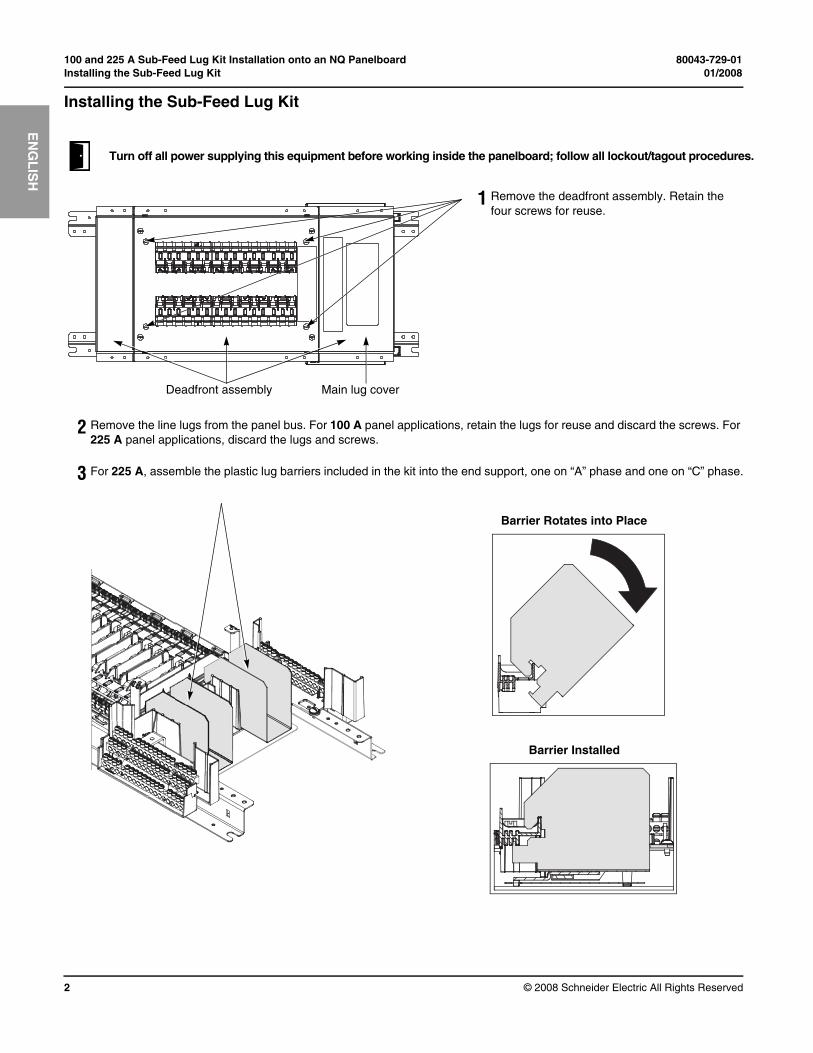
Turn off all power supplying this equipment before working inside the panelboard; follow all lockout/tagout procedures.
1 Remove the deadfront assembly. Retain the four screws for reuse.
2 Remove the line lugs from the panel bus. For 100 A panel applications, retain the lugs for reuse and discard the screws. For 225 A panel applications, discard the lugs and screws.
3 For 225 A, assemble the plastic lug barriers included in the kit into the end support, one on “A” phase and one on “C” phase.
Deadfront assembly Main lug cover
Barrier Rotates into Place
Barrier Installed

80043-729-01 100 and 225 A Sub-Feed Lug Kit Installation onto an NQ Panelboard01/2008 Installing the Sub-Feed Lug Kit
© 2008 Schneider Electric All Rights Reserved 3
EN
GL
ISH
NOTE: For step 4 and step 5, do not overtighten the screws.
4 Install the line lugs included in the kit on the panel bus using the 1/4-20 x 7/8-inch tapping screws included in the kit. For 100 A, add the lugs retained from step 2 (refer to 100 A graphic below) using the screws included in the kit. Tighten to 25–30 lb-in (2.8–3.4 N•m).
NOTE: Middle lug is installed for three-phase panels only.
5 Install the neutral lug included in the kit to the neutral bar using one 1/4-20 x 9/16-inch tapping screw included in the kit. Tighten to 25–30 lb-in (2.8–3.4 N•m).
6 Additional step for a 225 A panelboard:
Install the rail extensions to the end of the existing mounting rail using rail splices and eight 10-32 x 5/16-inch tapping screws included in the kit.
100 A Lugs Installed
225 A Lugs Installed
Rail splice Rail extension

100 and 225 A Sub-Feed Lug Kit Installation onto an NQ Panelboard 80043-729-01Installing the Sub-Feed Lug Kit 01/2008
EN
GL
ISH
Electrical equipment should be installed, operated, serviced, and maintained only by qualified personnel. No responsibility is assumed by Schneider Electric for any consequences arising out of the use of this material.
© 2008 Schneider Electric All Rights Reserved
Schneider Electric USA252 North TippecanoePeru, IN 46970 USA1-888-SquareD (1-888-778-2733)www.us.SquareD.com
7 Additional step for a 225 A panelboard:
Remove the existing main lug cover (see step 1) and discard, but retain the two screws. Mount the main lug cover included in the kit using the two retained screws.
8 Remount the deadfront assembly using the screws retained from step 1.
For technical support on the installation of this kit, contact the Square D/Schneider Electric Customer Information Center at 1-888-SquareD (1-888-778-2733).
Deadfront assembly
Main lug cover