1-specification for the management of stormwater policy 230209.doc
DESCRIPTION
FormTRANSCRIPT

SPECIFICATION FOR THE MANAGEMENT OF STORMWATER
Date of Adoption: 20 June 2006
Effective Date: 20 June 2006
Revised February 2009
CITY ASSETS

Specifications for the Management of Stormwater
Owner: Technical Services and Operations - City Assets Page 2 of 49Last Revised: 11/03/2009
Contents
1. Introduction .................................................................................................................................... 5
PART A - STORMWATER DRAINAGE CONTROLS FOR DEVELOPMENTS................................... 6
1. Types of Stormwater Drainage Controls......................................................................................... 6
2. On-Site Stormwater Detention Systems......................................................................................... 6
2.1 General .................................................................................................................................... 6
2.2 Site Storage Requirement and Permissible Site Discharge for OSD Design ............................ 6
2.3 Allowable Rainwater Re-use Deductions.................................................................................. 7
2.4 Design Parameters for OSD design used in the Site Specific Method ...................................... 7
2.5 Tailwater Influences ................................................................................................................. 8
2.6 Control Types........................................................................................................................... 8
2.7 Orifice Types............................................................................................................................ 8
2.8 Trash Screens.......................................................................................................................... 9
2.9 What Must Drain to the OSD SYSTEM?................................................................................... 9
2.10 Detention Storage Facilities to be used ................................................................................ 10
2.11 Overland Flows .................................................................................................................... 12
2.12 Freeboard ............................................................................................................................ 12
2.13 Discharge Points .................................................................................................................. 12
2.14 Drainage to a Different Catchment ....................................................................................... 13
2.15 Legal Obligations ................................................................................................................. 13
3. On-Site Stormwater Absorption Systems ..................................................................................... 14
3.1 General .................................................................................................................................. 14
3.2 Design Principles ................................................................................................................... 14
3.3 Minimum Design Criteria ........................................................................................................ 14
4 Charged Systems ......................................................................................................................... 15
4.1 General .................................................................................................................................. 15
4.2 Minimum Design Requirements ............................................................................................. 15
5 Mechanical Pumps-Out Systems .................................................................................................. 16
5.1 General .................................................................................................................................. 16
5.2 Minimum Requirements ......................................................................................................... 16
5.3 Minimum Pump and Sump Specifications .............................................................................. 17
6 Scouring and Erosion Control ....................................................................................................... 18
6.1 General .................................................................................................................................. 18
6.2 Minimum Requirements ......................................................................................................... 18
6.3 Soil and Water Management Plan.......................................................................................... 18
7 Rainwater Re-Use......................................................................................................................... 19
7.1 BASIX Minimum Requirements .............................................................................................. 19
7.2 Rainwater Re-use and OSD................................................................................................... 19
8 Submission Requirements ............................................................................................................ 19

Specifications for the Management of Stormwater
Owner: Technical Services and Operations - City Assets Page 3 of 49Last Revised: 11/03/2009
8.1 Development Application Stage ............................................................................................. 19
8.2 When Stormwater Drainage Easements are required............................................................. 20
9 Construction Certificate................................................................................................................. 20
10 Occupation Certificate................................................................................................................. 21
PART B - STORMWATER DRAINAGE SYSTEMS.......................................................................... 22
1. Stormwater Conveyance.............................................................................................................. 22
2 Stormwater Disposals ................................................................................................................... 22
3 Minor and Major System Design ................................................................................................... 22
3.1 Minor System Design ............................................................................................................. 22
3.2 Major System Design ............................................................................................................. 23
4 Hydrology...................................................................................................................................... 24
4.1 Rainfall Data .......................................................................................................................... 24
4.2 Average Recurrence Interval.................................................................................................. 24
4.3 Catchment Area ..................................................................................................................... 25
4.4 Determination of Catchment Runoff ....................................................................................... 25
4.5 Roughness Coefficients for the Calculation of Free Surface Flow .......................................... 25
5. Hydraulics .................................................................................................................................... 26
5.1 Hydraulic Grade Line Analysis ............................................................................................... 26
5.2 Downstream Hydraulic Controls ............................................................................................. 26
6 Pits................................................................................................................................................ 27
6.1 Location of Pits....................................................................................................................... 27
6.2 Pit Types................................................................................................................................ 27
6.3 Inlet Capacity ......................................................................................................................... 28
7. Open Channels............................................................................................................................ 28
8. Building Adjacent to Stormwater Drainage Systems .................................................................... 29
9. Stormwater Connections.............................................................................................................. 29
9.1 Under Buildings...................................................................................................................... 29
9.2 Above-Ground Pipe Work ...................................................................................................... 29
10. Services..................................................................................................................................... 29
11. Easements................................................................................................................................. 29
12. Inter-Allotment Drainage ............................................................................................................ 30
13. Stormwater Pollution and Erosion Control.................................................................................. 30
13.1 Soil and Water Management Plan........................................................................................ 30
13.2 Soil Erosion Control.............................................................................................................. 30
13.3 Integrated Developments ..................................................................................................... 31
14. Submission of Design Details..................................................................................................... 31
14.1 Submission Details............................................................................................................... 31
14.2 Information to be submitted.................................................................................................. 31

Specifications for the Management of Stormwater
Owner: Technical Services and Operations - City Assets Page 4 of 49Last Revised: 11/03/2009
APPENDIX....................................................................................................................................... 32
A1 Terms of Restriction on the Use of Land and Positive Covenant Existing Allotments.................. 32
Terms of Restriction on the Use of Land ...................................................................................... 32
Terms of Positive Covenant ......................................................................................................... 32
A2 Terms of Restriction on the Use of Land and Positive Covenant New Sub-divisions................... 34
Terms of Restriction on the Use of Land referred to in the above mentioned Plan ....................... 34
Terms of Positive Covenant referred to in the above-mentioned Plan .......................................... 34
A3. Absorption Design Storage Method (Ref Rockdale Council's Stormwater Design Code) ........... 36
A4 ILSAX Rainfall Files for the 5-yr, 20-yr and 100-yr ARI Storm Events ......................................... 37
5-yr ARI stacked rainfall ............................................................................................................... 37
20-yr ARI stacked rainfall ............................................................................................................. 39
100-yr ARI stacked rainfall ........................................................................................................... 41
A5 Standard Drawings ..................................................................................................................... 43

Specifications for the Management of Stormwater
Owner: Technical Services and Operations - City Assets Page 5 of 49Last Revised: 11/03/2009
1. IntroductionThis Specification for the Management of Stormwater compliments the City of Canada Bay Council's Stormwater Policy.
It has been prepared to provide guidelines for the management of stormwater runoff from all types of developments within
the City of Canada Bay Council Local Government Area (LGA).
The objectives of Council's Stormwater Policy are:
To provide uniform guidelines and application of systems to achieve consistency in the assessment and
conditioning of development applications in relation to stormwater runoff from all developments
To minimise any adverse impact on properties caused by stormwater runoff from developments
To ensure that the water qualities of receiving waterways are not adversely affected by pollutants such as
nutrients, pathogens, and situation, resulting from development sites.
To ensure that uniform stormwater controls are applied throughout the whole of the City of Canada Bay Council
Local Government Area.
These Objectives are achieved by the following controls:
The provision of safe overland flowpaths within developments and on public land
The definition of floodways for major storms within developments and on public land
The provision of controls such as on-site stormwater detention, community basins and the like and on-site
retention systems to reduce and control stormwater runoff
The application of alternative methods of merit based stormwater control and conveyance devices
The removal of flood effected development from known floodways and the prohibition of future developments in
such floodways
The provision of minimum free-boards for assigning floor levels to reduce the risk of flood damage to property
The installation of pipe/channel systems to minimise hazard to pedestrian and vehicular traffic caused by
uncontrolled surface stormwater runoff
The installation of water quality control devices such as trash screens, gross pollutant traps, water quality ponds
and the like to protect the quality of receiving waters.
The guidelines to achieve the above controls are provided in this document.

Specifications for the Management of Stormwater
Owner: Technical Services and Operations - City Assets Page 6 of 49Last Revised: 11/03/2009
PART A - STORMWATER DRAINAGE CONTROLS FOR DEVELOPMENTS
1. Types of Stormwater Drainage ControlsDifferent types of stormwater controls for development sites are permitted. However, their use will depend on the
circumstances applicable to the development. For example, any constraint affecting the use of one type or types of
stormwater control system may be required as an alternative to be implemented or systems to be used in combination to
satisfy Council's Policy objectives.
The following controls may be applicable:
On-site stormwater detention systems
On-site stormwater absorption (retention) systems
Charged systems
Pump-out systems
Direct discharge systems incorporating scour and erosion control devices
Rainwater re-use
A combination of some or all of the above to achieve Policy objectives
2. On-Site Stormwater Detention Systems
2.1 General
On-site Stormwater Detention (OSD) systems are to be implemented to control the rate of runoff from development sites
and subdivisions to limit or reduce the rate of runoff to existing conditions or better.
Alternative methods of stormwater control may be substituted but are merit based and is permitted only if OSD is found to
be impractical, or not feasible.
In general, OSD will be applied to all developments except in the following situations:
The proposal is a residential development such as alterations and additions to an existing dwelling, consisting of
an additional impervious area of not more than 50sqm outside the footprint of the existing building.
The proposal consists of improvements to the existing dwelling such as a second floor extension, which is within
the footprint of the existing dwelling.
The development is located within a known flood affected area, which is subject to tidal influence. This does not
include areas where it is affected by nuisance flooding caused by inadequate drainage systems. Council should be
consulted in this matter for further clarification.
The Applicant can demonstrate, to Council's satisfaction, that the site is at the lower reaches of the catchment and
that the application of an OSD system will not provide affective attenuation of the flows to achieve Policy
objectives.
The development generates runoff which is directly discharged into one of the bays or waterways and that the
runoff from the development is not conveyed by a public drainage system at any point in the system nor passes
through a public roadway or that no downstream properties could be adversely affected by the increased flow.
An alternative method of stormwater control is to be applied such as an on-site absorption facility, which satisfies
Council's Drainage Policy.
Please note that new residential developments (e.g. knock-down/re-build), residential flat buildings, commercial use,
industrial use and mixed used developments are not exempt from OSD.
An exemption from OSD for any development will require an alternative control system approved by Council to be
implemented. Alternative systems are discussed in the later chapters of this document.
2.2 Site Storage Requirement and Permissible Site Discharge for OSD Design
a) Catchment Based Method - for single residential developments has been adopted. The parameters are as follows:
The Site Storage Requirement (SSR) shall be 200cum per ha
The Permissible Site Discharge (PSD) shall be 180L/s per ha

Specifications for the Management of Stormwater
Owner: Technical Services and Operations - City Assets Page 7 of 49Last Revised: 11/03/2009
b) Catchment Based Method - for commercial, industrial, mixed, dual occupancy developments and residential flat buildings
(RFBs) has been adopted. The minimum parameters are as follows:
The Site Storage Requirement (SSR) shall be 300cum per ha.
The Permissible Site Discharge (PSD) shall be 200L/s per ha.
c) Site Specific Method - has been adopted for new land subdivisions.
New allotments created in excess of 450sqm or more and new roads are covered here. Dual occupancy subdivisions are
covered by the Catchment Based Method.
The minimum design criteria are explained below. The Site Storage Volume (SSV) shall be sized to cater for the 5-yr ARI
(low level), 20-yr ARI (intermediate level) and 100-yr ARI (high level) storm events for all time durations.
The general criteria are to ensure that the discharge after the development does not exceed the discharge prior to the
development, or better. For alterations and additions, the permissible site discharge is calculated on the existing footprint of
the dwelling before the improvements. For new dwellings, the permissible site discharge is based on a pre-developed
footprint of not more than 35% of the total site area or the existing footprint of the dwelling, whichever yields the smaller
discharge value. If the site drains to the rear, or is a commercial, industrial or multi-residential (including residential flat
building) development, the permissible site discharge is to be calculated on a 'state of nature' or 'green fields' site. In all
cases, the existing condition or better is to be maintained.
If the discharge from the development is to be concentrated at a single point (e.g. to the kerb and gutter) in the road reserve
or public land, the maximum concentrated discharge must be limited to no greater than 25L/s per 15 lineal metre of
frontage. This will be the maximum allowable discharge from the site should the existing discharge, as calculated above
(PSD) exceed this. The site storage volume should be upsized accordingly.
In the determination of the SSV and PSD, the ILSAX program for urban stormwater drainage design and analysis, Version
2.13 April 1993 or later, or the DRAINS program for urban stormwater system design and analysis, Version 2001.1 by
Geoffrey O'Loughlin and Bob Stack, April 2001 or later, are to be used.
Please note that the designer may choose to use this method to calculate the storage volume and site discharge instead of
the Catchment Based Methods as outlined above, for greater flexibility when less area (up to 50% of the total site) is to be
routed through the detention system.
2.3 Allowable Rainwater Re-use Deductions
If rainwater re-use systems are to be included, for example, as part of the BASIX or Council's Rainwater Re-use Policy
requirements, the re-use volume may be permitted to be fully deducted from the SSV. However the maximum allowable
deduction shall not exceed the minimum volume as calculated in the BASIX Certificate or Council's Rainwater Re-use
Policy. The PSD shall be retained for all controlled outflows.
2.4 Design Parameters for OSD design used in the Site Specific Method
The following design parameters are to be used, where applicable, in the model analysis:
Soil type = 2.5
Antecedent moisture content, AMC = 3
Infiltration rates:
Initial paved = 1mm
Grassed = 5mm
Storms, generated in accordance with the Australian Rainfall and Runoff, Volume 1, 1987 or later Editions.
Time of concentration, calculated using the kinematic wave equation given in the Australian.
Rainfall and Runoff, Volume 1, 1987, page 300, or program generated.
For the purpose of determining the time of concentration, the length of flow, L, is the distance from the furthest
point of the site to the exit point.
The surface roughness, n* is as given in the Australian Rainfall and Runoff, Volume 1, 1987, page 300.
The slope is the average gradient of the flowpath.

Specifications for the Management of Stormwater
Owner: Technical Services and Operations - City Assets Page 8 of 49Last Revised: 11/03/2009
Type '0' inlets are not to be used.
Supplementary areas are not to be used.
Graph showing relationship between orifice size and discharge is attached but can be estimated using the
following equation:
Q = C.A.√ (2.g.h)
Where:
A = area of orifice outlet in sqm
h = depth of water above centreline of orifice outlet in metres
C = discharge coefficient = 0.6*
g = acceleration due to gravity = 9.81m/s2
Q = discharge rate in m3/s or 103 L/s
* Note: This value is for a flat plate cut with a square edged circular shaped orifice. 'C' varies between 0.5 to 1.0 depending
on the type of outlet control to be used. A pipe stub of approximately 100mm long may be permitted for diameters greater
than 90mm. Smaller diameter pipe stubs are not acceptable due to the possibility of frequent choking and blockages.
Please note that the accuracy of the controlled outflow may not be achieved when a pipe stub is to be used instead of an
orifice plate.
2.5 Tailwater Influences
Should OSD systems connect directly into the existing receiving drainage system and the water level at the point of
connection is higher than the orifice centre-line level, the OSD will have a "drowned outlet" or is downstream controlled.
When this occurs, tailwater influences will affect the discharge rate, which is undesirable.
Outlet control or a 'drowned orifice' is generally unacceptable due to inaccuracies (too many variables introduced) into the
model, which may inadvertently cause discharge greater than the PSD. When this occurs, hydraulic calculations will need
to be submitted. The designer should size the control system taking into consideration pit losses, pipe friction and tailwater
conditions to achieve the PSD. The hydraulic check shall be carried out for the 5-yr, 20-yr and 100-yr ARI storm events to
demonstrate that the PSD is being achieved for all storm conditions.
Friction and head losses in pipes and pits may also affect outlet control, even though the point of connection is lower than
the orifice. A hydraulic grade line check may be necessary to ensure that the rate of discharge from the OSD system will
not be affected. Council may request for this information if deemed necessary.
The peak flowrate to the receiving drainage system can be calculated using the ILSAX or DRAINS program. Hydraulic
calculations can be performed using a computer software such as DRAINS or manually. For more complex models (eg
water surface profiles in creeks or rivers), the HEC-RAS program can be used.
Manual calculations are to be carried out in accordance with current design practices and principals as outlined in the
Australian Rainfall and Runoff, volume 1, 1987 or later editions and this Code and shall be submitted by a suitably qualified
person with experience in hydrology and hydraulics.
2.6 Control Types
Various outlet control devices to be used to control the rate of discharge from the OSD system are as follows:
High Early Discharge Control (HED) - to be used when applying the Catchment Based Method. If not using a HED
control facility, add 20% storage on top of the calculated basic storage volume. A HED system can still be adopted
when applying the Site Specific Method provided the model is set up to represent HED control. A 20% addition is
not required if the Site Specific Method is used.
Normal Control (N) - to be used for the Site Specific Method.
2.7 Orifice Types
Three (3) main types of orifice controls are applicable. These being:
Flat Plate - a flat stainless steel plate, 3mm in thickness and approximately 200mm x 200mm minimum dimension
(dependent on the outlet size) is fixed onto an oversized pipe outlet. The circular shaped orifice of specified
diameter is pre-drilled centrally into the plate. This hole is tooled to the exact calculated dimension to obtain the

Specifications for the Management of Stormwater
Owner: Technical Services and Operations - City Assets Page 9 of 49Last Revised: 11/03/2009
required outflow rate. The plate is to be permanently fixed into the wall of the control pit with four (4) 'dyna' bolts to
prevent its unauthorised removal.
The advantage of using an orifice plate is it provides the designer greater flexibility and accuracy in controlling the rate of
outflow.
The orifice equation to be used is:
Q = C.A.√ (2.g.h)
For a square-edged orifice,
C = 0.6
The above equation can be re-arranged to obtain the required diameter for the maximum discharge.
For a circular shaped orifice, the diameter:
D = √ (4.A/π)
Where
A = area of orifice hole in m2
π = 3.1416
Pit Loss and Pipe Friction - the control is determined by calculating the friction and entry losses in the outlet pipe
and pit leading from the OSD facility to the point of connection (or in reverse), to control the discharge rate. This
method would require hydraulic grade line calculations for various storm events and duration and best suited to
'drowned outlets'. However, 'drowned outlets' are not recommended.
Manual calculations are to be carried out in accordance with current design practices and principals as outlined in the
Australian Rainfall and Runoff, volume 1, 1987 or later editions.
Pipe Stub - this type of control is not recommended because the diameter of the nominal pipe stub is not as
accurate as an orifice plate, which can be machined to the exacting dimension. A short stub of nominal length
approximately 100mm long can be used to control the rate of discharge from the OSD facility. The orifice equation
given above can be used to determine the outflow rate.
For a pipe stub orifice, C = 0.8
The advantage of a pipe stub is that it is a permanent fixture that is not easily tampered with. Pipe stubs are only permitted
for diameters greater than 90mm, to minimise the likelihood of chokes.
2.8 Trash Screens
A rustproof screen or cage is to be used to protect the outlet from potential blockages.
This screen or cage must be removable for ease of maintenance and inspections.
The screen or cage shall completely protect the outlet and be made from Lysaghts maxi-mesh RH3030 or similar material.
The minimum surface area of the screen is to be 50 times the area of the orifice outlet.
The screen or cage is to be located at a distance 1.5 times the orifice diameter or 200mm away, whichever is the greater.
Where possible, the main incoming line is to flow across the face of the mesh.
The screen or cage should also include a lifting handle for ease of removal for inspection and maintenance.
2.9 What Must Drain to the OSD SYSTEM?
Catchment Based Method
It is preferable to control the total site runoff through the OSD facility. An allowance of up to 30% may be permitted to
bypass the system where site constraints prevent 100% capture. Where-ever possible all the impervious areas should
be collected with the majority of the 30% bypass to be pervious surfaces.
For a bypass of 30%, an additional 20% increase in the basic calculated storage volume shall be applied and the PSD
shall be reduced by 20%. Proportional increase of the basic volume and reduction of the PSD shall apply between 0%
and 30% bypass.

Specifications for the Management of Stormwater
Owner: Technical Services and Operations - City Assets Page 10 of 49Last Revised: 11/03/2009
Site Specific Method
This method is to be used for all new land subdivisions and when more than 30% of the site is to bypass the OSD
system. However, not more than 50% of the site will be permitted to bypass the OSD system. Further reductions in
capture would give model instabilities and is therefore unacceptable. Again, try to ensure that the majority of the
bypass areas to be mainly pervious surfaces. More than 30% impervious area bypassing the OSD system is not
permitted, without Council consent. To minimise bypass, it may be necessary to install more than one OSD facility.
2.10 Detention Storage Facilities to be used
Underground Storage Systems
o Shall be designed and located to safely convey all stormwater flows to the Council road gutter or
drainage system. Otherwise, the storage facility is to be moved to a more suitable location.
o Where likely overflow from these facilities is to cross private property and a suitable overflow path cannot
be provided, the overflow shall be contained within an underground piped drainage system with a design
capacity equivalent to the peak 100-year ARI storm event. This underground system (both pits and pipes)
shall be designed to receive and fully contain controlled flows and overflows from the detention facility.
o Must be located external to all building footprints. This includes basements, ground floor parking areas,
garages, or patios unless all access points and emergency overflow provisions are external to the
structure.
o A surcharge path shall also be defined even where the 100-year ARI flows can be contained within the
system in case of blockages. Easements are to be created in private property over pipe systems and
surcharge paths.
o Are not to be used where suitable above ground storage facility is available
o Are to be designed to be structurally sound to adequately withstand all service loads
o Must be adequately soundproofed to minimise noise when stormwater is collected or discharged
o Must be graded to drain completely - permanent water pondage encourages insect infestation and is not
acceptable. Base of the structure is to have a minimum longitudinal gradient of 0.7% to the outlet
o Are to be located where they can be readily accessible for inspections and routine cleaning.
For SEPP5 developments, the OSD facility shall be located in common areas and not in private
courtyards
For strata subdivisions, the location is subject to Council assessment but the intent is to ensure
that the facility is located where it is easily accessible for routine inspections and maintenance
requirements, where it is easily accessible for routine inspections and maintenance
requirements
o Must be constructed from reinforced concrete, pre-fabricated material or proprietary systems approved by
Council. Atlantis units or equivalent types of systems are not to be used as detention storage due to
difficulties in maintenance and inspections
o Must have at least one (1) inspection access grate over the outlet - this inspection access must be a
minimum 600mm x 600mm in dimension
o Must be in accordance with AS2865 - Safe Working in a Confined Space to eliminate gas build-up. For
ease of maintenance at least one (1) additional access at the extreme corner of the tank must be
provided. Additional access or flushing points shall be provided for irregular shaped structures to allow for
routine cleaning and maintenance.
o Must have additional access points at distances of no less than 2500mm.
o Clearance height in the tank must not be less than 500mm. Gratings shall be installed and shall cover at
least 30% of the surface area of the structure if clearance is less than 500mm.
o Must have step irons where the tank depth exceeds 1200mm.
o Must be located outside the root zones of trees that are to be retained.
o Must be located in areas, which will not impede the flow of water or undermine existing structures or
services.

Specifications for the Management of Stormwater
Owner: Technical Services and Operations - City Assets Page 11 of 49Last Revised: 11/03/2009
o Must have minimum topsoil cover of no less than 600mm over the tank where it is to be located in
landscaped areas.
Above Ground Storage Systems in Landscaped Areas
o Shall be designed and located to safely convey all stormwater flows to the Council road gutter or
drainage system.
o Where likely overflow from these facilities is across private property and a suitable overflow path cannot
be provided, the overflow shall be contained within an underground piped drainage system with a design
capacity equivalent to the peak 100-year ARI storm event. This underground system (both pits and pipes)
shall be designed to receive and fully contain controlled flows and overflows from the detention facility.
o Must be located external to all building footprints, basements, ground floor parking areas, garages, or
patios unless access points and emergency overflow provisions are either provided externally or is easy
to get to for the purpose of inspections and maintenance to the system.
o A surcharge path shall also be defined even where the 100-year ARI flows can be contained within the
system in case of blockages. Easements are to be created in private property over pipe systems and
surcharge paths.
o Shall include surface storage in soft and hard landscaped area or above ground structures such as
rainwater tanks.
o Must not be located across the boundary of an allotment.
o Must not be located such as to restrict pedestrian access from the public road to the building.
o Must be adequately soundproofed to minimise noise when stormwater is collected or discharged.
o Are to be located where they can be readily accessible for inspections and routine cleaning. For SEPP5
developments, the OSD facility shall be located in common areas and not in private courtyards. For strata
subdivisions, the location is subject to Council assessment but the intent is to ensure that the facility is
located in an area, which is easily accessible for routine inspections and maintenance requirements.
o If a built structure is to be used to retain water, it shall be of masonry type construction or waterproof
(prefabricated) material.
o Control structures must be located where they can be easily accessed for routine inspections and
cleaning.
o Must be graded to drain completely - gradients shall not be less than 1.0%. Where gradients are less
than 1.0%, sub soil drains and pits shall be installed.
o To avoid ground saturation in landscaped areas, subsoil drains shall be installed.
o Shall be designed in a manner, which minimises inconvenience, unsightliness and hazard.
o Must not allow water to pond more than 300mm in tennis courts or other surfaced areas.
o Must not allow water to pond more than 300mm in landscaped areas unless access by persons can be
restricted.
o Must not have batter slopes greater than 1 in 4.
o Where the depth of ponding exceed 300mm in landscaped areas, it must be fully fenced off with
approved pool fencing and childproof, self-closing gates with batter slopes into the basin, around its
perimeter, not to exceed 1 in 6.
o The maximum depth of ponding in landscaped areas must not exceed 1200mm.
o Where above-ground structures such as rainwater tanks are to be used, they must be located in an area
least visually obtrusive and in compliance with Councils planning requirements.
Above Ground Storage Systems in Paved Driveways and Carparks
o Shall be designed and located to safely convey all stormwater flows to the Council road gutter or
drainage system. Otherwise, the storage facility is to be moved to a more suitable location.
o Where likely overflow from these facilities is across private property and a suitable overflow path cannot
be provided, the overflow shall be contained within an underground piped drainage system with a design

Specifications for the Management of Stormwater
Owner: Technical Services and Operations - City Assets Page 12 of 49Last Revised: 11/03/2009
capacity equivalent to the peak 100-year ARI storm event. This underground system (both pits and pipes)
shall be designed to receive and fully contain controlled flows and overflows from the detention facility.
o Must be located external to all building footprints. This includes basements, ground floor parking areas,
garages, or patios unless all access points and emergency overflow provisions are external to the
structure.
o A surcharge path shall also be defined even where the 100-year ARI flows can be contained within the
system in case of blockages. Easements are to be created in private property over pipe systems and
surcharge paths.
o Must not be located such as to restrict pedestrian access from the public road to the building.
o Control structures must be located where they can be easily accessed for routine inspections and
cleaning.
o Must be graded to drain completely. Gradients shall not be less than 0.5%.
o Designed in a manner, which minimises inconvenience, unsightliness and hazard.
o Must be totally impermeable.
o Must not allow water to pond more than 200mm in depth.
2.11 Overland Flows
Surface runoff or overland flows from the site or from upstream properties passing through the site is not permitted to
concentrate, increase, re-directed or otherwise onto any other property. This may require diverting existing surface flows
safely to the street or into the OSD facility.
Where this runoff is to be controlled through the OSD facility, the OSD system must be designed to cater for the additional
inflow.
Provision must also be made for emergency overflows from the OSD system. Overflow weirs or spillways must be provided
for unexpected blockages or flows in excess of the design storm. Likely overflow from these facilities must be fully
contained within designated flow paths. These flow paths shall be designed for the peak 100-year ARI storm event.
Open channels, kerbs, pits and pipes may be used to contain runoff within the flow path. The width of overflow weirs shall
not exceed more than 2000mm across any property frontage.
2.12 Freeboard
Adequate freeboard or clearance between the maximum depth of ponding in the OSD system and the levels of all habitable
floor areas, garages, storage facilities, etc., is to be provided so that damage to goods and materials, nuisance flooding, or
hazard is avoided.
Developments will not be permitted within known floodways unless it can be proven that the development will not be
affected by floodwater nor will the development cause flooding both upstream or downstream of the development. Council's
Policy is the removal of such flood affected developments from known floodways and the prohibition of future developments
in such floodways, where necessary.
For OSD facilities and overflow paths, the following freeboard requirements will be required:
150mm - warehouse, factory and carport floor areas.
300mm - office, living rooms, retail space, store rooms, and show rooms.
For Flood waters (100-year flood level and PMP).
300mm - to enclosed garages and carparks.
500mm - to all internal building floor levels which includes residential, commercial and retail.
2.13 Discharge Points
The maximum concentrated stormwater discharged to a point in the kerb and gutter is to be limited to 25L/s at any single
point (note that discharge from the site is restricted to the permissible site discharge in any circumstance). Where the
permissible site discharge (as calculated in Section 2.2) exceeds 25L/s, it should be taken to the nearest Council drainage
system, or to an approved piped drainage system or stormwater channel. Alternatively the on-site stormwater detention
system can be upsized (where on-site detention is required) to accept additional flows to limit the outflow to 25 L/s or if
there is sufficient frontage, to split flows to the kerb (minimum 15 metres apart as described in Section 2.2).

Specifications for the Management of Stormwater
Owner: Technical Services and Operations - City Assets Page 13 of 49Last Revised: 11/03/2009
If there are no alternative ways of reducing the outflow including upsizing of the on-site detention facility or insufficient
separation of outlet points, the approval of concentrated discharge of more than 25L/s to the kerb will require the
submission of supporting calculations to show that the flow width or spread of stormwater along the gutter does not exceed
more than 2.5m across the roadway at any point in the gutter. Any contributing runoff from the upstream catchment must be
included in the calculations.
Discharging stormwater into a watercourse or channel may be permitted subject to joint approval from Council and other
relevant authority. Where approval is granted, adequate protection against scouring and erosion at the point of discharge
shall be provided. Council should be consulted in regards to appropriate stabilisation treatment to be used.
The maximum discharge velocity into an unlined, that is, other than concrete channel shall be in accordance with the
Department of Sustainable Natural Resources document Managing Urban Stormwater, Soils and Construction, table
5.1 maximum discharge flow velocities in waterways.
Where an existing Council drainage line is available, connection into the system may be permitted subject to Council
approval. The connection may require the construction of new inlet pits and the laying of a new pipeline, to Council
standards. Refer to Part B for minimum standards required.
Council encourages minimising the number of pits, junctions and pipe lengths in the road reserve. However, pits are
preferable over bend joins to eliminate blind junctions such that ease of maintenance can be achieved.
Any private stormwater pipe leaving the site, must be laid at an angle of no less than 45 degrees to the boundary line. If the
pipe needs to be laid at a more acute angle or must run parallel with the kerb line in order to achieve gravity discharge to
the kerb, then it must be taken to the kerb at minimum of 45 degrees and then a minimum 375-dia RCP is to be laid parallel
to the kerb line to the connection into the nearest downstream underground public drainage system. Standard gully inlet pits
with minimum 1.2 metre long kerb lintels will need to be constructed at any bends, junctions and minimum spacing of pits
as described in Part B, Section 6.
Conduits piped to the kerb must be sized adequately with at least 50mm cover. Where cover is inadequate, the following
pipe equivalencies shall be used:
100mm-dia equivalent to one (1) 100mm x 100mm x 6mm thick RHS
150mm-dia equivalent to one (1) 200mm x 100mm x 6mm thick RHS
225mm-dia equivalent to two (2) 200mm x 100mm x 6mm thick RHS
Outlets through existing sandstone kerbing - drilling through sandstone kerbing may be permitted subject to Council
approval.
The pipe class must also be adequate to withstand traffic loads.
All RHS are to be hot-dipped galvanised or stainless steel material.
2.14 Drainage to a Different Catchment
Stormwater drainage should follow the natural fall of the land and should be discharged by a gravity system. Diverting
stormwater runoff from one catchment (or sub-catchment) to another catchment (or sub-catchment) is generally not
permitted.
Council will only approve drainage against the natural grade of the land in the following circumstances:
Downstream property owners have indicated that they are not prepared to grant easements to permit the drainage
of the property to follow the natural fall of the land; and
Council has assessed that the proposed receiving drainage system can adequately cope with the additional runoff.
Where approval is granted, alternative methods of control/stormwater disposal such as 'charged systems', On-site
stormwater absorption (OSA) or a combination of these are to be designed in accordance with this Specification.
2.15 Legal Obligations
OSD facilities, and some pump-out and charged systems will require a Positive Covenant and Restriction on the use of
land, in favour of the City of Canada Bay Council on the Title.

Specifications for the Management of Stormwater
Owner: Technical Services and Operations - City Assets Page 14 of 49Last Revised: 11/03/2009
The purpose of the Covenant is to ensure that the registered proprietor takes responsibility for the control, care and
maintenance of the OSD, OSA and/or charged system. The Restriction ensures that the system is not altered in any
manner, shape or form.
For newly created parcels of land, these terms shall be created under Section 88B of the Conveyancing Act 1919. For
existing titles, the terms of positive covenant and restriction on the use of land shall be created by an application to the
Land Titles Office using Forms 13PC and 13RPA.
Standard wording for positive covenant and restriction on the use of land are given in the appendix.
3. On-Site Stormwater Absorption Systems
3.1 General
On-site stormwater absorption (OSA) systems may be permitted if easements for stormwater disposal through adjoining
downstream properties cannot be obtained. However, the criteria for which absorption is allowed will depend greatly on
satisfying the criteria as stated below.
If OSA is achievable, it should be located in soft landscape areas, such as in the garden, other vegetated on-ground areas.
However, in 'hard' landscaped areas, the use of porous pavement (pervious paving) is preferred.
If OSA is available, all stormwater collected from the roof and paved areas, that is, all impervious surfaces, are to be
directed into the system. A fail safe overflow outlet must also be installed to ensure that any overflows will be directed safely
to the street.
In general, absorption systems will only be acceptable in the following circumstances:
A stormwater drainage easement cannot be obtained through downstream properties because of resident
objections or physical constraints. Evidence in the form of signed documents from the adjoining owners must be
submitted to Council to prove that easement acquisition is unavailable.
Following unsuccessful acquisition of easements, the Applicant submits a Geotech Report, showing at least one
(1) bore log at the proposed location of the absorption facility, which indicates that the soil has sufficient absorptive
characteristics to consider it appropriate. An absorption system design is to accompany the report.
If the development is for an extension of less than 50sqm, second floor addition within the footprint of the existing
residential dwelling or the residential development has a total impervious area of less than 35% (including roof and paved
areas), then a Geotech Report will not be required. The design shall be based on the use of lineal trenches of 'Jumbo 410'
type or equivalent material. The trench length is to be 4 meters for every 25sqm of catchment (hard stand, roof) area
draining to it. An access chamber is to be provided at each end of the system.
3.2 Design Principles
The principle of design, for any development, is to ensure that all runoff is fully contained within an absorption system, for
all storm events up to a including the 100-yr ARI storm event. In this regard, all the impervious areas of the site shall be
drained into the OSA system. Where necessary, OSD may also be required to reduce the rate of discharge prior to inflow
into the OSA system.
3.3 Minimum Design Criteria
The soils must not be predominantly loose aeolian sands or clay soils.
A soil assessment and permeability test is required from a qualified Geotech Engineer.
Clearance distance between all buildings, footings, structures and downstream boundaries are to be at least 3.0
metres from the proposed absorption system. Minimum clearances are not to be reduced without a supporting
Geotech Report.
The minimum clearance distance between sewer mains and the proposed absorption system is to be at least 2.0
metres unless approved by Sydney Water. Where clearance between buildings or structures to the OSA system
cannot be provided, the structure is to be supported on a pier and beam system to a minimum 300mm below the
base of the OSA system, which must be certified by a Structural Engineer.
Absorption systems shall not be located under or over any sewer service without Sydney Water approval.
Absorption systems are not to be located in rock, most non-sedimentary rocks, or some sedimentary rocks such
as shale, which have zero or near-zero permeability.

Specifications for the Management of Stormwater
Owner: Technical Services and Operations - City Assets Page 15 of 49Last Revised: 11/03/2009
The minimum design storm recurrence interval shall be the 100-yr ARI storm event.
There is sufficient pervious (open space) area to allow complete percolation of runoff into the ground.
Absorption systems are not permitted in shallow soil over bedrock.
Suitable soils must have a uniform thickness of at least 3.0 metres.
Absorption systems will not be permitted on 'steep' sites with slopes greater than 5%.
Absorption trenches must follow the line of contours.
Absorption systems will not be permitted where there is the presence of a high water table or that the location of
the absorption system would likely to cause the water table to rise.
Where a high water table is encountered, the base of any proposed gravel filled trench shall be set at least 500mm
above the water table.
Where rock is encountered, the base of any proposed gravel filled trench shall be set at least 500mm above the
rock.
Direct uncleansed stormwater into the absorption system is not permitted.
Only roof runoff shall be permitted to directly discharge into the absorption system, but must pass through an
approved filter system to remove all debris, silts, sands, etc. prior to absorption.
Areas such as courtyards, walkways, driveways, carriageways, car parks, etc., are not to be piped directly into
absorption systems. A silt/trash or filtration system to be installed.
Runoff must pass across at least 15 metres of grass or through a sand/loam filter at least 200mm thick with grass
cover where impervious areas are to run directly to the absorption system.
Suitable soils must have hydraulic conductivity values greater than 1 x 10⁻⁶ m/s and the minimum absorption rate
to be adopted shall be limited to 1.0 L/sqm per second irrespective of the absorption rate achieved by any
geotechnical testing.
To ensure likely overflows are not concentrated onto adjoining downstream properties, a dispersion system shall
be provided at the overflow outlet.
In some cases, a combination of OSD and absorption may be required to control and detain the site runoff.
The Storage Method with average rainfall intensity may be used (see appendix for method based on Rockdale City
Council's Stormwater Code).
4 Charged Systems
4.1 General
Where a site naturally falls to the rear, and the property is not benefited by any stormwater drainage easement, a 'charged
system' may be considered for single residential dwellings, which are not classified as Complying Developments, to convey
stormwater to the street frontage. However, charged systems are not to be used if a gravity feed system can be achieved.
Other types of developments such as residential flat buildings, dual occupancies, commercial, mixed developments and the
like are generally not permitted unless the following constraints apply:
Downstream property owners have indicated that they are not prepared to grant easements to permit the drainage
of the property to follow the natural fall of the land. Written evidence is to be submitted as proof.
Soil absorption characteristics and other physical constraints indicate that on-site absorption is not feasible for the
dwelling to be totally catered for by any absorption system. A Geotech Report, indicating that the soil has very
poor absorption rate, is to be submitted as proof.
Council has assessed that the proposal to discharge to the street's receiving drainage system can adequately
cope with the additional runoff.
Please note that the approval of charged systems does not negate OSD requirements. However, it may not be possible or
practical to be able utilise charged systems if OSD is required. In such circumstances, a mechanical pump-out system used
in combination with OSD or OSA may be more practical. Note though that mechanical pump-out systems are not preferred
over charged lines due to high installation and ongoing maintenance costs.
4.2 Minimum Design Requirements
The following design requirements must be satisfied:

Specifications for the Management of Stormwater
Owner: Technical Services and Operations - City Assets Page 16 of 49Last Revised: 11/03/2009
Charged lines generally suitable for direct pipe from the roof gutter to the street.
Overflows from rainwater re-use systems are to be directed to an OSA system unless details and supporting
calculations can be provided showing that sufficient pressure head can be generated to direct flows to the street
via a charged system.
Outflows from OSD systems are generally to be by gravity with 'free outlet' control. However, 'drowned outlets'
may be permitted if supporting calculations can be provided showing that sufficient pressure head can be
generated to direct flows to the street via a charged system and that the permissible discharge from the site can
be maintained.
Full hydraulic analysis of the proposed drainage system is to be submitted including design flowrates and a
hydraulic grade line.
The drainage system including roof gutters pipes and pits and is to be designed for the 1 in 100-year ARI storm
event.
There is a minimum height difference between the roof gutter level and the discharge pit of 2.0 metres to allow
sufficient pressure to drain the system. Alternatively, a hydraulic grade line for the 1 in 100-year ARI storm event
shows that the system can drain to the street with a 300mm free board to the gutter line.
The charged line shall discharge to a sump within the property boundary and then gravity fed to the street or
receiving drainage system. Typical details of the boundary pit to achieve this can be obtained from Council. Where
gravity feed to the street is not achievable, a non-return valve must be installed over the inlet pipe to the sump.
However, non-return valves are generally not recommended due to maintenance problems.
The discharge pit is to be located such that any likely overflow is safely directed to the street.
Pipes should be minimum 150mm-dia pipes for pressure applications and solvent welded unless hydraulic
calculations show that a smaller pipe can be installed but pipes less than 80mm-dia is not recommended.
Cleaning eyes must be installed at the lowest point in the system within a sump, which is to be drained into an on-
site absorption/dispersal system.
Gutter guards are to be installed to minimise debris entering the system.
All utility services within the road reserve must be located and shown on the plan in relation to the proposed
drainage system.
A positive covenant will be required to be placed on the title of the property to inform the owners of their obligation
to regularly maintain the system.
Full detailed drawings and supporting calculations shall be submitted to Council with the Development Application.
5 Mechanical Pumps-Out Systems
5.1 General
Mechanical pumps are generally to be used to convey sub-surface, or seepage water in a basement car parking area or for
the drainage of minor surface runoff collected from weather exposed areas of less than 50m².
The pumping out of stormwater runoff in general is not permitted unless:
Gravity drainage cannot be achieved.
An easement cannot be obtained through downstream adjoining properties. Written evidence to be provided in
support of argument.
A 'charged system' is not possible to drain on-ground areas.
An alternative method of stormwater disposal such as OSA, is not suitable for the site.
Adjoining properties will not be inconvenienced in the event of pump failure.
Council has assessed that the proposed receiving drainage system can adequately cope with the additional runoff
being diverted to it.
5.2 Minimum Requirements
The direct connection of the pump rising main into the kerb/gutter will not be permitted. The pumped water must be
conveyed across the public footway by gravity means and drained into an underground public drainage system.
Direct discharge into the kerb/gutter encourages slime build-up and constant wetness and is unacceptable.

Specifications for the Management of Stormwater
Owner: Technical Services and Operations - City Assets Page 17 of 49Last Revised: 11/03/2009
For direct connection into an existing stormwater pipe, a pit must be constructed at the point of connection and a non-return
valve must be installed on the upstream (inlet) pipe to prevent water flowing back into the property. Non-return valves shall
be installed in a junction pit within the property boundary. Non-return valves are not permitted to be installed in Council
maintained (public) systems.
When connecting into a Council stormwater system on public land, two (2) pits; a junction pit on the property fitted with a
non-return valve and a standard stormwater gully pit at the connection point in the road reserve, may be necessary.
Water pressure in the system must be taken into consideration as this could affect the design discharge rate, rendering it
unsuitable to achieve the required outflow. Where a charged system is likely, supporting calculations are to be submitted to
verify that the system can operate in accordance with this Specification.
5.3 Minimum Pump and Sump Specifications
The following minimum requirements for pumps shall apply:
The pump system shall consist of two (2) pumps, connected in parallel, with each pump being capable of emptying
the holding tank at a rate no greater than the PSD or portion of the PSD where all or part of the site runoff is to be
conveyed to the kerb.
The pump must be capable of draining the subsoil inflow rate and any minor surface runoff collected from weather
exposed areas of less than 30m2.
The sump must be designed to be capable of accommodating/holding runoff from all weather exposed areas
during a peak 100-year ARI storm event for duration of no less than 5 hours and any subsurface inflow rate during
wet weather determined by an approved test procedure or estimated value.
The capacity of the holding tank shall be calculated as above the level at which all pumps are automatically
brought into operation.
The minimum capacity of the holding tank well shall be adequately sized in accordance with AS/NZS3500.3.2 -
1998, National Plumbing and Drainage, Part 3.2: Stormwater drainage - acceptable solutions.
A silt trap shall be provided on the inlet side of the holding tank.
The rising main from the pump system shall be designed and installed in accordance with the pump
manufacturer's specification.
The rising main from the pump system shall discharge to a stilling sump within the property boundary and then
gravity fed to the street or receiving drainage system.
A one-way valve is to be installed on the rising main outlet. The stilling sump is to be located such that any likely
overflow is safely directed to the street.
The switching of the pumps shall be arranged so that they operate alternately.
The pumps shall be provided with automatic level switches so that they operate simultaneously should the
capacity of the tank be exceeded.
An automatic alarm system shall be provided to warn of failure of any part of the pump system.
The alarm shall have visual indicators and an audible alarm siren.
A rechargeable battery back-up system for the alarm is to be provided in the event of power failure.
Prior to the issue of the Final or Occupation Certificate, the applicant shall submit written evidence that a contract
has been let for the regular maintenance of the pump system (does not apply to single residential developments).
The creation of a positive covenant affixed to the title of the property indemnifying Council against liability in
respect of any damage sustained as a result of the failure of the pump system, damage to neighbouring property
or any other cause not in Council's control, and providing for regular inspection by the proprietor.
The covenant also identifying the person(s), or authority responsible for the maintenance of the system.
The following information shall be submitted with the application:
Piping size tabulation sheet - for the rising main.
Copy of pump specification and pumping curves.
Graph showing the maximum design inflow curves and pump curves for both pumps.
A plan of the pump system layout showing pits, pipes and sizes, invert levels and discharge point.

Specifications for the Management of Stormwater
Owner: Technical Services and Operations - City Assets Page 18 of 49Last Revised: 11/03/2009
Drawing of the holding tank and pumps including invert level, pump cut in levels, alarm level, etc.
Any other calculation and documentation considered necessary in support of the application.
6 Scouring and Erosion Control
6.1 General
Where drainage is to a natural watercourse, into bushland/reserve, or water way, adequate controls are required to protect
adjoining properties, bushland, roadways and receiving waters from degradation due to silt laden stormwater runoff and/or
the concentration of runoff, as a result of development. Notwithstanding other stormwater controls that may be required
such as on-site stormwater detention, appropriate scour and erosion control devices are to be installed at the outflow to the
system.
6.2 Minimum Requirements
Minimum controls shall be provided as follows:
Appropriate scour protection devices installed at the outlet to stormwater conduits; and
Installation of pollution control devices at the source, on-line*, off-line or at the end of the line to control sediment
laden overland stormwater flows.
*Note: stormwater management measures shall not be located on-line in water courses or within riparian zones or areas of
remnant native vegetation.
Scour protection devices shall include embankment stabilisation e.g. rock walls, concrete aprons, gabions, turfing, jute
mesh, energy dissipating units, or other more appropriate erosion control devices approved by Council. Preference is for
'soft engineering' solutions.
Please note that stormwater devices are not appropriate within or adjacent to creek locations. In this regard, The
Department of Planning and NSW Fisheries shall be contacted for advice about suitable erosion control measures here.
Control devices may also be necessary as part of a development to remove pollutants during the 'first flush'. These devices
shall be installed within the site and may include proprietary items such as Humeceptors or CDS units, silt and grease
arrestors approved by Council. Installation of these devices shall be in accordance with the manufacturer's specification.
Other sediment control devices such as stilling basins and constructed wetlands shall be required for large-scale
developments. Council will provide guidelines as to when these are required as part of the Conditions of Consent. These
shall include land and community title subdivisions. Design of these devices shall be in accordance with the Managing
Urban Stormwater, Soils and Construction Manual by the NSW Department of Housing.
It will also be necessary to install silt traps in all stormwater pits to contain silt and debris. Silt traps shall be installed at the
bottom of pits at a depth of 200mm to capture silts and fines. Weep holes shall be drilled into the base of the pit to ensure
that it does not permanently hold water and create a breeding ground for insects. Where the pit is located over impervious
material, subsoil drains will also need to be laid.
6.3 Soil and Water Management Plan
A soil and water management plan must be submitted with all development applications, except for minor developments
such as an extension to an existing dwelling of less than 50sqm. If unsure, please check with Council as to whether this is
required for a particular development.
This Plan must be approved by Council prior to the commencement of any works.
Minimum guidelines shall be in accordance with the Managing Urban Stormwater, Soils and Construction Manual by
the NSW Department of Housing, August 1998.
All sediment control devices are to be installed prior to any commencement of clearing and earthworks on the site. Ongoing
maintenance of these devices during construction will be required.
Council may request a maintenance schedule to ensure that the devices are cleaned on a regular basis.

Specifications for the Management of Stormwater
Owner: Technical Services and Operations - City Assets Page 19 of 49Last Revised: 11/03/2009
7 Rainwater Re-UseNotwithstanding BASIX water conservation targets, the collection of rainwater for non-potable use is encouraged. Non-
potable water usage shall include watering of the garden, irrigation, washing machine and toilet flushing. Rainwater re-use
requirements are either in accordance with Council's Policy or BASIX. Reference should be made to Council's Rainwater
Re-use Policy for further details and minimum guidelines.
7.1 BASIX Minimum Requirements
BASIX is a web-based planning tool designed and developed by Department of Planning in association with other
government agencies and utilities to assess the water and energy efficiency of new residential developments.
On 1 July 2004, the NSW Government introduced BASIX into the development approval system such that new homes will
use less water and energy.
New houses and dual occupancy developments in Sydney, unless a development applicant entered into a building
agreement before 1 July 2004 or an agreement on or after 1 July as a consequence of an offer made or deposit paid before
1 July 2004, will be required to submit a BASIX certificate.
Part of BASIX requires the installation of rainwater re-use facilities. The volume of storage required depends on the size of
the dwelling, the number of amenities and other site factors.
To obtain a BASIX certificate, development applicants complete an online assessment using the BASIX tool and enter in
site parameters applicable to the proposed development. Further details can be obtained at www.basix.nsw.gov.au.
The re-use volume determined from the BASIX Certificate will be regarded as the minimum re-use volume allowable for the
development. Additional storage is encouraged but subject to Council's planning requirements.
7.2 Rainwater Re-use and OSD
Council encourages the re-use of rainwater. However, the inclusion of a rainwater re-use system does not negate the
requirement for OSD, where OSD is not exempted according to the criteria given in this Code for exemptions. However,
Council will allow a deduction of the volume of rainwater re-use to be taken off the calculated OSD storage volume
determined in Section 3.
The maximum volume as determined using the BASIX tool or as required in Council's Rainwater Re-use Policy will be
permitted to be deducted from the basic OSD calculated site storage volume. Additional storage beyond what has been
determined in BASIX or in Council's Rainwater Re-use Policy will not be permitted to be deducted from the calculated
OSD volume.
The re-use component shall be deducted from the calculated OSD volume by straight subtraction of volumes. A credit of
100% of the calculated re-use volume is permitted for toilet flushing, irrigation and watering gardens.
The permissible site discharge (PSD) is not to be adjusted.
Dual usage for both OSD and re-use in the same tank is permitted. OSD will generally be provided in the upper chamber
and re-use to be provided in the lower portion. Please check with Council's Planning Section regarding the maximum size of
the tank to be used to ensure that it will not conflict with planning requirements. In this regard, it is advisable to obtain a
copy of Council's current Rainwater Tank Policy for further information regarding minimum volumes for developments and
to obtain more information about stored rainwater for non-potable usage such as irrigation, watering garden, toilet flushing
etc.
Please note that tank sizes of more than 10,000 litres will require DA approval in accordance with SEPP4.
When designing dual-purpose tanks, consideration must be made for the collection of rainwater from the site. OSD control
applies to the total site but re-use generally is collected from the roof of the dwelling only. A dual-purpose OSD/re-use
facility that collects only rainwater from the roof may permit much of the site area to be uncontrolled. Therefore careful
design needs to be considered to ensure that the majority of the site, especially the roofed areas, can be controlled through
an OSD system.
8 Submission Requirements
8.1 Development Application Stage
At the lodgement of the Development Application (DA) a stormwater drainage concept plan (SDCP) shall be submitted. It is
advisable that the Applicant submit an SDCP to satisfy that the proposed development is feasible. This SDCP must show

Specifications for the Management of Stormwater
Owner: Technical Services and Operations - City Assets Page 20 of 49Last Revised: 11/03/2009
the general layout of the proposed drainage system, with indicative levels, minimum pipe sizes, and location of the OSD
and/or OSA facilities including basic volumes and dimensions, overflow routes and points of discharge etc, to demonstrate
that the development can be adequately catered for and complies with Council's Drainage Policy.
Most importantly, the main issues which need to be shown is the proposed system in relation to any services such as to
ensure that there will be no clashes with any services and that the system can operate hydraulically.
An SDCP particularly for sites which drain to the rear would be required. This is to demonstrate to Council that the site can
be drained without resulting in nuisance flooding or other detrimental factors.
8.2 When Stormwater Drainage Easements are required
Where the site grades to the rear, drainage easements would be necessary. Evidence in the form of a Legal Agreement
between affected parties or copies of titles showing the creation or intension to create easements must be provided to
Council in support of the Development Application. This is essential for DA approval. Where easements cannot be
negotiated, signed documents by all affected parties shall be submitted to support the case for alternative solutions.
9 Construction CertificatePrior to the issuing of the Construction Certificate (CC) either by Council or a nominated Principal Certifying Authority
(PCA), the final drainage plan should include but not limited to the following:
A1, A2 or A3 size drawings clearly showing the layout of the proposed drainage system, including the location of
all downpipes, pits and pipes and labelled with their pipe sizes, gradients, existing and finished surface and invert
levels, the dimensions of OSD and OSA systems, proposed storage volumes, surcharge/overflow paths, site
discharge, etc.
All supporting computation information including calculations on computer disc (where applicable) with relevant
hydrologic and hydraulic information.
Computation information summarised as:
Total site area in m2.
Total impervious area (roof and paved) in m2.
Area draining into the proposed stormwater (OSD or OSA) facility.
Dimensions (mm), volume (cum), and discharge rate from the OSD or OSA system.
Maximum water depth (mm) from centreline of outlet to top water level.
Maximum depth of ponding for above ground OSD systems.
Type and size of orifice (mm-dia), outlet pipe (mm-dia) and PSD (L/s).
Drawings must be certified by a qualified practising Civil Engineer for residential flat buildings, dual occupancies,
commercial, industrial, mixed developments, multi-residential developments, and the like. For single residential
developments, residential extensions, and small scale developments, a draftsman, surveyor, or plumber with
experience in stormwater design would be acceptable.
Where drainage easements are required, evidence in the form of a legal agreement between the affected parties
or copies of titles showing the created easements and a longitudinal section of the proposed pipe to the point of
connection or to the discharge point for drainage to foreshore areas and where discharge is permitted to
waterfronts or bushland. This shall include pipe sizes, gradients, flowrates and a hydraulic grade line which shall
include pipe sizes, gradients, flowrates and a hydraulic grade line.
Details of the OSD control device(s) used including size and shape, outlet pipe diameter and invert level.
For underground systems, at least one (1) detailed section through the OSD or OSA facility sufficient for
construction.
For above ground systems, at least two (2) detailed sections through the OSD facility, which shall include the
maximum water level, gradients and overflow weir, sufficient for construction.
Existing and proposed levels and details of adjoining structures and buildings shall be shown on the sections
through the OSD or OSA facility.
Overland flow path and PSD from the site.
Plan showing the location of OSA or OSD facilities including dimensions, pervious (landscape) and paved (existing
and proposed roof and paved) areas, and all existing and proposed surface levels.

Specifications for the Management of Stormwater
Owner: Technical Services and Operations - City Assets Page 21 of 49Last Revised: 11/03/2009
For pump-out systems, relevant information as requested in Section 5.
Location of any utility services*, structures, trees, etc., which may affect the proposed drainage system.
*Note: It is the responsibility of the applicant to submit full details of all relevant services, which may conflict with the
proposed design. The exact locations of any crossings or connections are to be shown.
10 Occupation CertificatePrior to the issuing of an Occupation Certificate, the following information must be submitted to Council:
Works-as-executed drawings: an engineering survey of the final works is to be submitted on one (1) set of the
approved plans. This plan is to include finished levels, dimensions and volume of the built OSA, OSD facility, the
location of all drainage pipes, sizes and levels, etc., and signed by a Registered Surveyor.
Copies of titles showing the creation of Positive Covenants and Restriction on the use of land.
Certification of the constructed drainage system by a suitably qualified and experienced Chartered Professional
Engineer, on the National Professional Engineers Register with the Australian Institute of Engineers for residential
flat buildings, dual occupancies, commercial, industrial, mixed developments, multi-residential developments, and
the like. For single residential developments, residential extensions, and small scale developments, a Certificate
from a Surveyor or plumber with experience in stormwater design would be acceptable.
Identification Plate: at Council's request, an identification plate of no less than 110mm wide x 80mm high, is to be
fixed near or onto the control structure of the OSD system, this is to advise the registered proprietor of their
responsibility to maintain the OSD facility and not to tamper with it in any manner without written consent. This
plaque shall read 'This is an On-site Stormwater Detention system. It is an offence to reduce the volume of this
system or to remove the orifice that controls the outflow. The base of the outlet control pit and debris screen must
be cleared of silt and rubbish on a regular basis. This plate must not be removed.'

Specifications for the Management of Stormwater
Owner: Technical Services and Operations - City Assets Page 22 of 49Last Revised: 11/03/2009
PART B - STORMWATER DRAINAGE SYSTEMS
1. Stormwater Conveyance Stormwater drainage conveyance referred to herewith are the systems which are designed to convey stormwater runoff.
This includes property drainage, street drainage (both piped and surface flow paths), and trunk drainage (larger conduits,
open channels) and receiving waters (rivers, creeks, groundwater storage, sea and ocean).
Stormwater drainage systems will be necessary to collect and convey stormwater runoff from a site to a receiving waterway
with minimal nuisance, danger to life or damage to properties.
The pollutants which are carried by stormwater shall be minimised by designing the system with the following inclusions:
Have adequate sub-surface drainage to provide protection to structures, and prevent long term water ponding.
Have adequate inlets to collect and convey surface stormwater runoff to prevent water from entering buildings or
damage structures, minimise nuisance and danger to persons and vehicular traffic, prevent long term surface
water ponding, prevent erosion, and protect adjoining and downstream properties from any adverse impacts as a
result of stormwater runoff from proposed developments.
Include a system of overland flowpaths, where possible, to provide fail-safe protection to buildings, structures,
adjoining and downstream properties in the event of pipe blockage or storm events that generate greater runoff
than the capacity of the piped drainage system.
This can be achieved by:
o The construction of surface flow routes to convey floodwaters away from private and public properties
and that, in flood prone land, the velocity and depth of flows are controlled to an acceptable level.
o The provision of surface flow routes and piped drainage systems to direct/control frequent runoff, so that
convenience and safety to pedestrians and vehicle traffic, can be provided.
o The provision of both piped drainage and surface flowpaths for new developments, re-developments and
new subdivisions.
o The installation of water quality control devices such as gross pollutant traps, basins, baskets and the like
to collect pollutants present in stormwater runoff.
2 Stormwater DisposalsStormwater runoff shall follow the natural fall of the land and must be disposed by gravity means, whenever possible. Re-
directing stormwater runoff from one catchment (or sub-catchment) to another catchment (or sub-catchment) is not
permitted. Council will not approve drainage systems which diverts stormwater runoff to another catchment by going
against the natural grade of the land for any development. This includes land subdivisions and road drainage design. Re-
directing stormwater using pump-out or charged systems is permitted for residential and commercial developments and re-
developments as discussed above. Disposal of stormwater on-site by absorption is also covered in Part A.
3 Minor and Major System Design The method of stormwater drainage design used to size pipe networks and trunk drainage systems to convey stormwater
runoff to the receiving water is known as the "dual drainage" system approach or minor/ major design concept, as described
in the Australia Rainfall and Runoff. This method has been adopted by Council and a summary of the design criteria are set
out below.
3.1 Minor System Design
The gutter and pipe network capable of conveying stormwater runoff during minor storm events is known as the "minor
system".
When designing the minor system, adequate inlet pits are to be installed such that the maximum gutter flow widths shall not
exceed the lesser of 2.5 metres or one-quarter of the road carriageway width.
Wider flow widths may be accepted on roads whose cross-sectional gradients are less than 1.0%. This is subject to Council
approval.

Specifications for the Management of Stormwater
Owner: Technical Services and Operations - City Assets Page 23 of 49Last Revised: 11/03/2009
The minimum conduit sizes for the minor system design shall be as follows:
Public system - pipes, 375mm-dia
Public system - box culverts, 600mm wide x 450mm high
Private system - 90mm-dia for roof runoff only
Private system - 100mm-dia for surface runoff within the property only
Roads - pipes, 375mm-dia
The minimum pipe grade shall be as follows:
For pipes less than or equal to 225mm-dia - 3%
For pipes greater than 225mm-dia - 1.0%
For concrete lined box culverts poured in-situ - 0.5%
Pipes which are to be laid at a slope greater than 20% will require anchor blocks at the top and bottom of the section and at
intervals of not more than 3.0 metres in between. Bulkheads shall be provided on steep gradients where soil instability is
likely. To retain backfill material, bulkheads shall be installed at intervals of not more than 5.0 metres.
Type of pipe material and jointing to be used for the minor system design shall be as follows:
Public system - reinforced or fibre reinforced concrete*, rubber ring jointed.
Private system - up to 300mm-dia uPVC, solvent welded joints; 300mm-dia and larger reinforced or fibre
reinforced concrete*, rubber ring jointed.
Subject to Council approval, other types of piping material, for larger conduits, such as plastic pipes may be used, if it can
be demonstrated that the substitute material has the same, if not better, structural and durable qualities than reinforced
concrete.
Depth of cover to the conduit obvert shall be as follows:
Public system not subject to vehicle loads - 450mm
Pubic system subject to vehicle loads - 600mm
Private system not subject to vehicle loads - 300mm
Private system subject to vehicle loads - 600mm
Where it is not practical to provide for the above minimum cover requirements, at least 50mm thick granular overlay shall be
provided over the obvert of the conduit with a 150mm thick reinforced concrete slab constructed over it or mass concrete
surround.
The appropriate class of pipe to be used shall depend on the minimum cover provided and the loading onto the pipe in
accordance with AS3725 - 1989, loads on buried concrete pipes.
Design velocity of flows shall be:
Conduits - 0.6 m/s minimum, 6.0m/s maximum
Surface flow - 2.0m/s maximum
Where these values cannot be contained, appropriate erosion control measures are to be provided.
Maximum permitted depth of surface flow shall be:
Road carriageway, driveways, footpaths and carparks - 150mm
Landscaped areas - 300mm
3.2 Major System Design

Specifications for the Management of Stormwater
Owner: Technical Services and Operations - City Assets Page 24 of 49Last Revised: 11/03/2009
The "major system" comprises the drainage route, which conveys the runoff for the major storm events. This may be a
series of trunk drainage systems and overland surface routes including open channels, creeks, and river systems.
Overland flow routes are to be provided in the following locations:
Within the road carriageway excluding footpaths and the footway reserve. Flows across footpaths will only be
permitted where this will not cause flooding to property or create danger to pedestrians and is subject to Council
approval.
Within drainage easements. Where it is not practical to provide an overland flow route over the easement, the
piped drainage system shall be sized to accept the runoff for the major storm event i.e. the 100-year ARI.
Within a known and designated floodway.
Within creeks and river systems.
The minimum freeboard shall be as follows:
150mm for roadways - between the 100-year ARI overland flow route and warehouse, factory, and garage floor
levels and entrances to underground carparks.
300mm for roadways - between the 100-year ARI overland flow route and office, living rooms, retail space,
storeroom, and show room floor levels.
300mm for surcharge paths e.g. easements - between the 100-year ARI overland flow route and all internal
building floor levels, garages and basement carparks.
500mm for channels, creeks and rivers - between the 100-year flood water level and all internal building floor
levels, garages, and basement carparks.
Design velocities and depths of surface flows shall be in accordance with Figures G1 and G2 of the New South Wales
Government Floodplain Management Manual: The management of flood liable land, with hazard category classed as
"low hazard".
4 Hydrology
4.1 Rainfall Data
Rainfall data is given in the appendix.
4.2 Average Recurrence Interval
The Average Recurrence Interval (ARI) to be used to design major and minor drainage systems is as follows:
Minor System Design
Classification - public system; piped and channel drainage
LOCATION ARI (years)
Local roads 10
Collector roads 10
Sub-arterial roads 10
Arterial roads 20
State roads 50
Access to emergency facilities 100
At a depression (low point) in the road 100
Through private property with or 100
without a safe overflow route
Classification - private system; piped and channel drainage
LOCATION ARI (year)
Residential - low density 10*
Residential - medium to high 20*
Commercial 50*

Specifications for the Management of Stormwater
Owner: Technical Services and Operations - City Assets Page 25 of 49Last Revised: 11/03/2009
Industrial 50*
Hospitals and emergency facilities 100*
* Note: The underground drainage system (this includes pipes, conduits and pits) shall be designed for an ARI of 1 in 100-
years where major system flows (e.g. along a drainage easement) are likely to surcharge across private property or cause
localised flooding. A surcharge path must also be provided to safely convey surface stormwater across private property
within easements. The minimum design ARI for surcharge paths shall be the 1 in 100-years.
Major System Design
Classification - public system; overland flowpaths and trunk drainage systems
The design ARI shall be the 1 in 100-years.
Classification - private system; overland flowpaths and trunk drainage systems
The design ARI shall be the 1 in 100-years.
4.3 Catchment Area
The catchment area is defined by the limits from where surface runoff will make its way, either by man-made or natural
paths, to the point of exit.
4.4 Determination of Catchment Runoff
Catchment runoff shall be determined using a suitable hydrological method depending on the level of accuracy required
and the extent and shape of the catchment. The Rational Method or hydrological models may be used.
For more detailed description of each type of model, their limitations and applications are given in the Australian Rainfall
and Runoff.
Rational Method
The use of Rational Method for the estimation of peak flows will be acceptable for small catchments of sizes up to
1200sqm. Use of this method for larger catchments will be subject to available information and Council permission.
This method is best suited to catchments with uniform slope and roughness characteristics and where the level of accuracy
is not critical.
The method described in Australian Rainfall and Runoff for the calculation of overland flow times shall be employed. The
minimum values of surface roughness or retardance factors given in Australian Rainfall and Runoff are to be used.
Hydrological Computer Models
The use of hydrological computer models is best suited for medium to large catchments and where a reasonable level of
accuracy is required.
Acceptable computer models include ILSAX, DRAINS, RAFTS, and RORB. However, the preferred model is ILSAX or
DRAINS.
Where a computer model is to be used, the input and output data in electronic format and as a hard copy shall be provided
upon submission of the design drawings for approval.
Impervious Areas
Refer to the section for inter-allotment drainage design for determining the percentage impervious areas to be used in the
design of inter-allotment drainage systems for subdivisions, developments and re-developments.
Public, road and trunk drainage systems are to be designed for the following percentage impervious areas:
o minimum 50% for all residential areas,
o 100% in commercial areas, and
o 70% for road reserves
4.5 Roughness Coefficients for the Calculation of Free Surface Flow
For the purpose of determining stormwater runoff into open channels and free surface hydraulics, Manning's roughness
coefficients shall be used. Typical values are given in Section 7. open channels and in Australian Rainfall and Runoff.
For sections with composite roughness values, Horton's Equation may be used to convert to an equivalent roughness value
for simplicity in calculations.
Horton's Equation is given as:

Specifications for the Management of Stormwater
Owner: Technical Services and Operations - City Assets Page 26 of 49Last Revised: 11/03/2009
n = (Pi.ni 3/2) 2/3
Pi
where ni = is the Manning's roughness coefficient for section i and
Pi = is the wetted perimeter or length of the section with a roughness value ni
5. Hydraulics
5.1 Hydraulic Grade Line Analysis
Hydraulic grade line calculations are to be performed in accordance with the Australian Rainfall and Runoff, and shall be
undertaken by a qualified person with experience in hydrology and hydraulic design.
Full hydraulic calculations must be submitted for all public and major piped systems (375mm-dia and larger), drainage lines
through easements or where Council deems it necessary to determine the feasibility of the proposal.
Drainage lines shall be designed with minimal bend losses. Where this is unavoidable, junction pits shall be provided at the
location of bends or changes in direction.
Pipes will not be permitted to be laid such that a larger pipe joins into a smaller pipe downstream, to avoid potential chokes
in the system. However, this may be unavoidable when the new line is connected into an existing system. In this
circumstance, the starting hydraulic control shall be adopted at the ground level at the point of connection.
For surface drainage systems e.g. channels, open drains and the like, hydraulic calculations must include the determination
of the water surface profiles and backwater effects using suitable computer models such as DRAINS and HEC-RAS.
Frictional losses in closed conduits of circular cross-section e.g. pipes, shall be determined using the Darcy-Weisbach
Formula. This Formula may be applied to rectangular sections e.g. box culverts, by converting the product of the area and
hydraulic radius to the power of two-thirds (A.R2/3) to an equivalent circular section.
The following Colebrook-White roughness parameters shall be used:
uPVC , k=0.03mm
Reinforced concrete, k=0.60mm
Fibre reinforced concrete, k=0.60mm
Pit energy losses and pressure changes at junctions, bends, transition structures, slope junctions, inlet pits, junction pits,
drops and outlets must be considered.
Pressure head coefficients for determining these "head losses" are to be obtained from the following sources:
Missouri Charts
Hare Equations
U S Corp of Engineers mitre bend charts
AR&R 1987 or later editions
5.2 Downstream Hydraulic Controls
The downstream water surface level is to be adopted as one of the following:
Where the hydraulic grade line level downstream of the proposed works, including the upstream pit losses at the
starting pit is known (corresponding to the design storm recurrence interval as adopted), this level is to be used.
Where the downstream starting point is at a pit and its hydraulic grade line is unknown, a level of 150mm below
the surface level of this pit is to be adopted.
Where the outlet is to an open channel, the water surface level is to be determined using Manning's Equation or an
appropriate hydraulic model. The water level, shall be adopted as the normal depth, calculated using an
appropriate method, or the top of the outlet pipe, whichever is the greater.
Specifications for the Management of Stormwater
Owner: Technical Services and Operations - City Assets Page 27 of 49Last Revised: 11/03/2009
Where the outlet is to an open channel, and downstream flood levels are known, the water surface level to be
adopted shall be the 1% AEP flood level.
Where the outlet is affected by tidal or wave action, the resulting tide water level shall be adopted.
Where the outlet is to an existing pipe or conduit, the hydraulic grade line of the conduit shall be determined
downstream to a pit where its water level is known e.g. at a grate in the gutter where the maximum free surface
ponding is at the top of kerb.
Where the outlet is at the invert of the kerb, the water surface level shall be adopted at the top of the kerb.
6 Pits
6.1 Location of Pits
Stormwater drainage inlet pits shall be:
Spaced such that the gutter flow width is limited to 2.5 metres maximum width for the minor system design.
Located at the upstream side of allotments to minimise runoff flowing across the road.
Located at sag points and at road depressions.
Located where access for inspections and maintenance is readily available.
Provided at changes in direction, grade, conduit level, size, or class of conduit.
Provided at junctions.
Spaced at a distance of no greater than 50 metres apart.
6.2 Pit Types
Standard Council kerb inlet pits shall have minimum internal dimensions of 600 x 900 and shall have grated covers. Council
inlet pits in landscaped areas, and pavements other than at kerb locations, shall have minimum 600 x 600 internal
dimensions. Non-Council inlet pits may have smaller dimensions of 300 x 300 and 450 x 450 where minor runoff is to be
collected. However, where the depth of the pit exceeds 1.2 metres, the minimum internal dimension shall be 600 x 900
regardless of its design collection rate or location. Internal pit dimensions may be increased to suit the size and orientation
of the inlet and outlet pipes.
Private pits i.e. pits which collect/convey property runoff only, shall be located wholly within property boundaries. Pits, which
are to be located in public land, shall be constructed to Council standard and shall become part of the public drainage
system. This shall include drainage conduits and any other part of the drainage system considered relevant by Council.
Grates over Council pits are to be galvanised and hinged to frame with minimum dimensions of 450 x 900 for kerb inlet pits
and 450 x 450 for standard inlet pits not located at the kerb and gutter. Non-Council pits may have grates of minimum 300 x
300 to suit the internal dimensions of the pit. However these must not be less than 450 x 450 where the pit depth exceeds
1.2 metres. In the road carriageway, vehicle accessways, carparks and driveways, they are to be of heavy-duty
construction. In landscaped areas where vehicular traffic is unlikely, these can be of medium duty construction. Light duty
grates are not to be used except in landscaped areas and not where they are not subject to surcharge forces or pedestrian
traffic. All grates shall be grate and hinged combination and lockable.
Where pits are not designed to collect stormwater, solid concrete covers are to be used. These must be liftable for
inspections and maintenance. Junction pits are not to be designed as pressurised systems.
Where pits exceed 1.2 metres in depth, step irons in accordance with AS1657 are to be provided one side of the pit wall to
allow access for inspections and cleaning.
Letterbox type pits are not permitted at or near kerb locations where there is likely pedestrian and/or vehicular traffic. In
these locations, pits with butterfly type grates flush with the surrounding ground level are preferred.
Lintels shall be provided at the kerb side with the opening length dependent on its design capture rate but no less than 1.2
metres and not greater than 4.0 metres.
Pits are to be constructed of reinforced concrete. Pre-cast pits may be used subject to Council approval. All pits must be
watertight and structurally adequate for the intended traffic loads. Where proprietary products are to be used, the
manufacturer's specification will need to be submitted.
The bases of pits shall be concrete benched to minimise hydraulic losses.
Pits constructed of brick will not be acceptable unless they are designed and constructed to withstand structural loading.

Specifications for the Management of Stormwater
Owner: Technical Services and Operations - City Assets Page 28 of 49Last Revised: 11/03/2009
6.3 Inlet Capacity
The inlet capacity of pits shall be determined in accordance with the Australian Rainfall and Runoff.
Allowance must be made for blockages as follows:
Location Inlet Type Percentage of Theoretical
Capacity Allowed
sag side entry only 80%
sag grate only 80%
sag combination 100% side entry only grate assumed completely blocked
sag letterbox 50%
on-grade side entry only 80%
on-grade grate only 50%
on-grade combination 80%
7. Open ChannelsPiped systems are preferred over open channel systems. Open channels will only be permitted if they form part of the major
drainage system and where permitted, shall be designed to have smooth transitions, with adequate access provisions
available for inspections, general maintenance and adequate safety measures installed to protect persons and vehicles.
These include perimeter fences, bollards, and grills over outlet pipes. Step irons shall be installed; flow velocities and
depths reduced at nominated access points.
Open channels shall be designed in accordance with the Australian Rainfall and Runoff and the NSW Government
Floodplain Management Manual and should be able to contain the major system runoff.
Mannings roughness coefficients for open channel sections applicable to specific channel types shall be obtained from the
Australian Rainfall and Runoff.
Typical values are given below:
Mannings Roughness Coefficients
Surface n
Concrete pipes or box sections 0.012
Concrete trowel finish 0.015
Concrete formed without finishing 0.016
Sprayed concrete, granite 0.018
Bitumen, smooth finish 0.016
Bricks or pavers 0.016
Pitchers or dressed stone in mortar 0.016
Rubble masonry or random stone in mortar 0.028
Rock lining or rip-rap 0.028
Earth, clean 0.027
Corrugated metal 0.027
Earth, weed and gravel 0.022
Rock cut 0.028
Short grass 0.033
Long grass 0.035
Medium to dense brush 0.150
Open channels shall be designed to avoid hydraulic jumps or generate supercritical flow conditions.
Side slopes shall not exceed 1 in 4, unless fully fenced off.
Where-ever possible, low flows shall be contained within a piped system or contained within a concrete lined channel at the
invert of the channel.

Specifications for the Management of Stormwater
Owner: Technical Services and Operations - City Assets Page 29 of 49Last Revised: 11/03/2009
8. Building Adjacent to Stormwater Drainage SystemsWhere structural supports such as foundations, piers, and footings are to be located adjacent to the drainage system, they
should not be load bearing onto the underlying drainage structure. In general, where a drainage structure is parallel or
adjacent to foundations, piers or footings, the base of the footing shall be located outside the zone created by an angle of
45 degrees to the horizontal extended from the invert of the drainage structure.
9. Stormwater Connections
9.1 Under Buildings
Shall be carried out in accordance with AS/NZS3500.3, Section 3.
9.2 Above-Ground Pipe Work
Shall be carried out in accordance with AS/NZS3500.3, Section 6 and to this Specification.
10. ServicesCare shall be taken to ensure that the proposed stormwater drainage system will not conflict with utility services. In this
regard, all services shall be located prior to final drainage system design. Stormwater drainage conduits crossing over or
under sewer lines must be laid in accordance with Sydney Water's requirements. This may require support trenching and
concrete encasement of sections that traverse the utility.
Where drainage lines are to be laid in the road reserve, they shall be located under the kerb line or within the road
carriageway, to avoid conflict with the utility services in the footway. If drainage lines must cross the footway reserve, they
shall be laid across the footway perpendicular to or at a maximum angle of 45 degrees to the kerb face to minimise conflict
with services.
11. EasementsEasements for stormwater drainage shall be required over constructed drainage systems within private properties, to
ensure that Council has full rights of access to such drainage systems for the purpose of inspection, maintenance or
upgrade. Stormwater drainage easements shall be required for all inter-allotment drainage lines. Drainage easements will
not be required within or over natural drainage systems and watercourses. Council does not favour or encourages the
piping, construction within or over, or interference with natural drainage systems and watercourses. Any proposal to carry
out such works will be subject to an assessment pursuant to other relevant Council policies and joint approval from other
relevant authorities.
Council will take the opportunity to acquire drainage easements over existing constructed public drainage systems within
the private property whenever a development occurs by Condition of Consent.
When a developer or property owner proposes to relocate or reconstruct a public drainage system within the site, a
drainage easement in Council's favour must be created to suit the relocated or reconstructed drainage system at the cost to
the developer.
Any construction of buildings or other permanent structures over a public drainage easement is not permitted, unless the
encroachment still permits reasonable access for Council to construct and maintain the system, that it does not impede or
re-direct flows within the easement, that it does not load bear onto the underlying drainage structure, and that the site
cannot be reasonably developed without the encroachment over the easement (refer to Council's Policy on Drainage
Easements). Alternatively the conduit and easement may be relocated subject to Council approval.
Any structural support such as footings and piers will only be permitted to be located adjacent to an easement if they do not
load bear onto the underlying drainage structure, and that the built structure will not be undermined by any future
maintenance work necessary within the easement.
Planting of trees or large shrubs, particularly those with extensive root systems will not be permitted in drainage easements.
Construction over a public drainage easement is prohibited unless Council does not require future access to the drainage
structure for the life of the underlying structure. Public drainage easements must be free of encroachments with a minimum
vertical clearance from the surface ground level over the drainage structure to a height of 5.0 metres above. Paved
surfaces over the public drainage easement are permitted provided that construction joints along each longitudinal edge of
the easement are installed to facilitate access to the drainage structure.

Specifications for the Management of Stormwater
Owner: Technical Services and Operations - City Assets Page 30 of 49Last Revised: 11/03/2009
12. Inter-Allotment DrainageInter-allotment drainage shall be provided for every property that does not drain directly by gravity to its street frontage, to
an existing stormwater drainage system or to a natural watercourse.
Easements shall be created over all inter-allotment drainage in favour of all upstream properties benefited by it. Easement
width shall be a minimum width equal to the external width of the conduit plus 1.0 metre, rounded to the nearest 0.1 metre.
The impervious area to be used to determine the contributing runoff shall be the total impervious area to be collected by the
conduit within the allotment.
However, in the absence of more detailed information, the following impervious areas shall be adopted:
Type of Development Percentage impervious area of allotment
Road reserve 80%
Residential 90%
Medium Density 90%
Industrial 100%
Commercial 100%
These above figures are not to be used for pre-development calculations for the purpose of on-site detention sizing.
Inter-allotment drainage pits and pipes shall be of reinforced concrete, fibre reinforced concrete or uPVC material. Pipes are
to be rubber ring jointed or solvent welded as specified by the manufacturer and in accordance with AS4058, AS4139, and
AS1254 respectively.
13. Stormwater Pollution and Erosion Control
13.1 Soil and Water Management Plan
A soil and water management plan shall be submitted and approved by Council prior to the commencement of any drainage
works within the road reserve, other public land, or land subdivision works. Sediment control measures must be taken into
consideration during any development. Specification shall be in accordance with the Managing Urban Stormwater, Soils
and Construction Manual, NSW Department of Housing.
All sediment control devices are to be installed prior to any commencement of clearing and earthworks on the site. Ongoing
maintenance of these devices during construction will be required.
13.2 Soil Erosion Control
Soil erosion control is required to protect adjoining properties, bushland, roadways and receiving waters from degradation
due to silt laden stormwater runoff as a result of development and/or concentration of runoff.
Erosion control shall be provided as follows:
Appropriate scour protection installed at the outlet to stormwater conduits, and
Installation of pollution control devices at the source, on-line, off-line or at the end of the line to control
sediment laden overland stormwater flows.
Scour protection devices shall include embankment stabilisation e.g. rock walls, concrete aprons, gabions, turfing, jute
mesh, energy dissipating units, or other more appropriate erosion control devices approved by Council. Please note that
some types of scour protection devices may be inappropriate along certain creek locations. In this regard, the Department
of Lands may be contacted for advice about suitable erosion control measures.
Control devices may be required as part of a development to remove pollutants during the "first flush". These devices shall
be installed on line or within the site and may include proprietary items such as Humeceptors or CDS units, silt and grease
arrestors approved by Council. Installation of these devices shall be in accordance with the manufacturer's specification.
Other sediment control devices such as stilling basins, constructed wetlands shall be required for large-scale
developments. These shall include land and community title subdivisions.
Design of these devices shall be in accordance with the Managing Urban Stormwater, Soils and Construction Manual, NSW
Department of Housing, August 1998.

Specifications for the Management of Stormwater
Owner: Technical Services and Operations - City Assets Page 31 of 49Last Revised: 11/03/2009
13.3 Integrated Developments
Any development within 40m of a water body such as a stream, creek, lagoon, or river may require a Part 3a Permit under
the Department of Lands Guidelines and The Rivers and Foreshores Improvement Act 1948. A development of this nature
is classified as an Integrated Development. Advice should be sought from Council in this regard.
14. Submission of Design Details
14.1 Submission Details
A stormwater drainage concept plan (SDCP) must be submitted with the Development Application. Detailed design
drawings and calculations of the proposed stormwater drainage system must be submitted and approved prior to the issue
of the Construction Certificate by a suitably qualified person with experience in stormwater drainage design.
14.2 Information to be submitted
Engineering drawings shall be submitted as follows:
A3 or A1 size drawing sheets at an appropriate scale of 1:100, 1:200 or 1:500.
Showing the layout of the proposed drainage system including the location of all downpipes, kerbs, channels, open
drains, pits and pipes.
Showing the size and class of all stormwater conduits, grades, and pit dimensions.
Showing the invert and surface levels of all pipes and pits.
Showing the finished surface levels of any open channels, drains, or swales.
Showing the location of all buildings, driveways, impervious and pervious surfaces.
Showing the finished surface levels of paved areas, unpaved areas, building floors and garages.
Showing the flow widths and depth of ponding across road carriageways and floodways for the minor storm event,
if any.
Showing the overland flowpath for the major storm event.
Showing the extent of flow and depth of ponding for the major storm event.
Showing cross section details of any open channels, drains, or swales.
Where drainage easements are required, the location of the proposed easement for stormwater drainage and legal
agreements.
Showing a longitudinal section of the piped system to the point of connection including pipe sizes, class, gradients,
flowrates and a hydraulic grade line.
Showing details of the On-site Stormwater Detention System (OSD) or On-site Absorption (OSA) facilities, if any,
in accordance with this Code.
Include supporting computation information on computer disc (where applicable) and hard copy with relevant
hydrologic and hydraulic information and calculations.
Showing the location of any utility services, structures, trees, etc., which may affect the proposed drainage system-
Note: It is the responsibility of the applicant to submit full details of all relevant services, which may conflict with the
proposed design. The exact locations of any crossings or connections are to be shown.
Before Council can issue the Final Certificate, upon completion of the works, the following must be submitted:
o Works-as-executed drawings. An engineering survey of the final works is to be submitted on one (1) set
of the approved plans. This plan is to include all finished surface levels of pits, the location of all drainage
pipes, sizes and levels, etc., and signed by a Registered Surveyor.
o Copies of Titles showing the creation of easements, Positive Covenants, and restrictions on the land,
where applicable
o Certification of the constructed drainage system by a suitably qualified and experienced Chartered
Professional Engineer, on the National Professional Engineers Register with the Australian Institute of
Engineers.

Specifications for the Management of Stormwater
Owner: Technical Services and Operations - City Assets Page 32 of 49Last Revised: 11/03/2009
APPENDIX
A1 Terms of Restriction on the Use of Land and Positive Covenant Existing AllotmentsThe generic wording for the terms of restriction on the use of land and positive covenant are given below.
For existing allotments where there is no land subdivision, that is, there is no Section 88B instrument required, the following
wording for the "Terms of Restriction on the Use of Land" and "Terms of Positive Covenant" shall be attached to the NSW
Department of Lands standard forms 13RPA and 13PC respectively:
Terms of Restriction on the Use of Land
(Show full details of the Restriction)
The registered proprietors covenant with the City of Canada Bay Council (the Council) that they will not:
I) Do any act, matter or thing which would prevent the structure and works from operating in an efficient manner.
II) Make any alterations or additions to the structure and works or allow any development within the meaning of the
Environmental Planning and Assessment Act 1979 to encroach upon the structure and works without the express
written consent of the authority.
III) III) This covenant shall bind all persons who claim under the registered proprietors as stipulated in section 88E(5)
of the Act.
For the purposes of this covenant:
Structure and Works shall mean the on-site stormwater detention system constructed on the land as set out in the plan
annexed hereto and marked with the letter 'A' (or alternatively as detailed on the plans approved by Council or Private
Certifier No. {INSERT DA NUMBER/DRAWING NUMBER(S)/DESIGNER DETAILS/DATE/REVISION NUMBER}), including
all gutters, pipes, drains, walls, kerbs, pits, grates, tanks, chambers, basins and surfaces designed to temporarily detain
stormwater on the land.
The Act means the Conveyancing Act 1919.
Terms of Positive Covenant
(Show full details of Positive Covenant)
The registered proprietors covenant with the City of Canada Bay Council (the Council) that they will maintain and repair the
structure and works on the land in accordance with the following terms and conditions:
I) the registered proprietor will:
i. Keep the structure and works clean and free from silt, rubbish and debris.
ii. Maintain and repair at the sole expense of the registered proprietors the whole of the structure and works
so that it functions in a safe and efficient manner.
II) For the purpose of ensuring observance of the covenant the Council may by its servants or agents at any
reasonable time of the day and upon giving to the person against whom the covenant is enforceable not less than
two days notice (but at any time without notice in the case of an emergency) enter the land and view the condition
of the land and the state of construction maintenance or repair of the structure and works on the land.
III) The registered proprietors shall indemnify the Council and any adjoining land owners against any claims for
damages arising from the failure of any component of the OSD system, or failure to clean, maintain and repair the
OSD system.
IV) By written notice the Council may require the registered proprietors to attend to any matter and to carry out such
work within such time as the Council may require to ensure the proper and efficient performance of the structure
and works and to that extent section 88F(2) (a) of the Act is hereby agreed to be amended accordingly.
V) Pursuant to section 88F(3) of the Act the authority shall have the following additional powers pursuant to this
covenant:
i. In the event that the registered proprietor fails to comply with the terms of any written notice issued by the
Council as set out above the Council or its authorised agents may enter the land with all necessary
equipment and carry out any work which the Council in its discretion considers reasonable to comply with
the said notice referred to in (I) hereof.

Specifications for the Management of Stormwater
Owner: Technical Services and Operations - City Assets Page 33 of 49Last Revised: 11/03/2009
ii. The Council may recover from the registered proprietor in a Court of competent jurisdiction:
(a) Any expense reasonably incurred by it in exercising its powers under subparagraph (i) hereof. Such
expense shall include reasonable wages for the Council's own employees engaged in effecting the said
work, supervising the said work and administering the said work together with costs, reasonably
estimated by the Council, for the use of machinery, tools and equipment in conjunction with the said work
(b) Legal costs on an indemnity basis for issue of the said notices and recovery of the said costs and
expenses together with the costs and expenses of registration of a covenant charge pursuant to section
88F of the Act or providing any certificate required pursuant to section 88G of the Act or obtaining any
injunction pursuant to section 88H of the Act.
VI) This covenant shall bind all persons who claim under the registered proprietors as stipulated in section 88E(5) of
the Act.
For the purposes of this covenant:
Structure and Works shall mean the on-site stormwater detention system constructed on the land as set out in the plan
annexed hereto and marked with the letter 'A' (or alternatively as detailed on the plans approved by Council or Private
Certifier No. {INSERT DA NUMBER/DRAWING NUMBER(S)/DESIGNER DETAILS/DATE/REVISION NUMBER}), including
all gutters, pipes, drains, walls, kerbs, pits, grates, tanks, chambers, basins and surfaces designed to temporarily detain
stormwater on the land.
The Act means the Conveyancing Act 1919.

Specifications for the Management of Stormwater
Owner: Technical Services and Operations - City Assets Page 34 of 49Last Revised: 11/03/2009
A2 Terms of Restriction on the Use of Land and Positive Covenant New Sub-divisionsThe generic wording for the terms of restriction on the use of land and positive covenant are given below.
Where a subdivision has been lodged and a Section 88B instrument created, then the following wording for the "Terms of
Restriction on the Use of Land" and "Terms of Positive Covenant" is to be included:
Terms of Restriction on the Use of Land referred to in the above mentioned Plan
The registered proprietor covenant with the City of Canada Bay Council (The Council) in respect to the structure erected on
the land described as 'on-site stormwater detention system' (which expression includes all ancillary gutters, pipes, drains,
walls, kerbs, pits, grates, tanks, chambers, basins and surfaces designed to temporarily detain stormwater) shown on the
plans approved by Council or Private Certifier No. {INSERT DA NUMBER/DRAWING NUMBER(S)/DESIGNER
DETAILS/DATE/REVISION NUMBER} (herein called "the system").
The registered proprietors covenant with Canada Bay Council (The Council) that they will not:
I) Do any act, matter or thing which would prevent the structure and works from operating in an efficient
manner.
II) Make any alterations or additions to the structure and works or allow any development within the meaning of
the Environmental Planning and Assessment Act 1979 to encroach upon the structure and works without the
express written consent of the authority.
III) This covenant shall bind all persons who claim under the registered proprietors as stipulated in section
88E(5) of the Act.
For the purposes of this covenant:
Structure and Works shall mean the on-site stormwater detention system constructed on the land as set out in the plan
annexed hereto and marked with the letter 'A' (or alternatively as detailed on the plans approved by Council or Private
Certifier No.{ INSERT DA NUMBER/DRAWING NUMBER(S)/DESIGNER DETAILS/DATE/REVISION NUMBER}) including
all gutters, pipes, drains, walls, kerbs, pits, grates, tanks, chambers, basins and surfaces designed to temporarily detain
stormwater on the land.
The Act shall mean the Conveyancing Act 1919.
Terms of Positive Covenant referred to in the above-mentioned Plan
The registered proprietors covenant with the City of Canada Bay Council (The Council) that they will maintain and repair the
structure and works on the land in accordance with the following terms and conditions:
I) The registered proprietor will:
i. Keep the structure and works clean and free from silt, rubbish and debris.
ii. Maintain and repair at the sole expense of the registered proprietors the whole of the structure and works
so that it functions in a safe and efficient manner.
II) For the purpose of ensuring observance of the covenant the Council may by its servants or agents at any
reasonable time of the day and upon giving to the person against whom the covenant is enforceable not less
than two days notice (but at any time without notice in the case of an emergency) enter the land and view the
condition of the land and the state of construction maintenance or repair of the structure and works on the
land.
III) The registered proprietors shall indemnify the Council and any adjoining land owners against any claims for
damages arising from the failure of any component of the OSD system, or failure to clean, maintain and repair
the OSD system.
IV) By written notice the Council may require the registered proprietors to attend to any matter and to carry out
such work within such time as the Council may require to ensure the proper and efficient performance of the
structure and works and to that extent section 88F(2) (a) of the Act is hereby agreed to be amended
accordingly.
V) Pursuant to section 88F(3) of the Act the authority shall have the following additional powers pursuant to this
covenant:

Specifications for the Management of Stormwater
Owner: Technical Services and Operations - City Assets Page 35 of 49Last Revised: 11/03/2009
i. In the event that the registered proprietor fails to comply with the terms of any written notice issued by the
Council as set out above the Council or its authorised agents may enter the land with all necessary
equipment and carry out any work which the Council in its discretion considers reasonable to comply with
the said notice referred to in (I) hereof.
ii. The Council may recover from the registered proprietor in a Court of competent jurisdiction:
a. Any expense reasonably incurred by it in exercising its powers under sub-paragraph (i) hereof. Such
expense shall include reasonable wages for the Council's own employees engaged in effecting the said
work, supervising the said work and administering the said work together with costs, reasonably
estimated by the Council, for the use of machinery, tools and equipment in conjunction with the said work.
b. Legal costs on an indemnity basis for issue of the said notices and recovery of the said costs and
expenses together with the costs and expenses of registration of a covenant charge pursuant to section
88F of the Act or providing any certificate required pursuant to section 88G of the Act or obtaining any
injunction pursuant to section 88H of the Act.
VI) This covenant shall bind all persons who claim under the registered proprietors as stipulated in section 88E(5)
of the Act.
For the purposes of this covenant:
Structure and Works shall mean the on-site stormwater detention system constructed on the land as set out in the plan
annexed hereto and marked with the letter 'A' (or alternatively as detailed on the plans approved by Council or Private
Certifier No. {INSERT DA NUMBER/DRAWING NUMBER(S)/DESIGNER DETAILS/DATE/REVISION NUMBER}),
including all gutters, pipes, drains, walls, kerbs, pits, grates, tanks, chambers, basins and surfaces designed to temporarily
detain stormwater on the land.
The Act means the Conveyancing Act 1919.

Specifications for the Management of Stormwater
Owner: Technical Services and Operations - City Assets Page 36 of 49Last Revised: 11/03/2009
A3. Absorption Design Storage Method (Ref Rockdale Council's Stormwater Design Code)
Project: No 10 Blogg Street, Drummoyne
A = 409 sqm* total impervious area collected
C = 1 coefficient*
ARI = 100 years
Absorption rate = 0.00007 m/s*
Adjusted rate = 0.0000595 m/s minimum allowable clogging factor = 15%
(* variables to be entered)
length, L = 5 m*
width, B = 2.5 m*
depth, h = 1 m*
area = 12.5 sqm
Available storage = 12.5 cum
12500 litres
Checking storms
duration (min) intensity inflow rate (l/s) vi (l) vo (l) vi - vo (l)
5 241 27 8214 2231 5983
6 227 26 9284 2678 6607
7 211 24 10068 3124 6944
8 202 23 11016 3570 7446
9 194 22 11902 4016 7886
10 189 21 12884 4463 8421
12 174 20 14233 5355 8878
15 164 19 16769 6694 10075
20 144 16 19632 8925 10707
25 132 15 22495 11156 11339
30 120 14 24540 13388 11153
40 102 12 27812 17850 9962
45 97 11 29755 20081 9674
50 90.6 10 30880 22313 8567
55 85.8 10 32168 24544 7624
60 84 10 34356 26775 7581
65 77.9 9 34516 29006 5510
70 74.6 8 35597 31238 4359
75 71.5 8 36554 33469 3086
80 68.7 8 37464 35700 1764
85 66.2 8 38357 37931 426
90 66 7 40491 40163 329
100 59.8 7 40764 44625 -3861
120 55.3 6 45235 53550 -8315
180 42.7 5 52393 80325 -27932
270 32.3 4 59448 120488 -61039
Note: This method does not allow emptying time. It is assumed the trench fills and quickly empties instantaneously.
Since available storage is greater than the maximum storage required - ok

Specifications for the Management of Stormwater
Owner: Technical Services and Operations - City Assets Page 37 of 49Last Revised: 11/03/2009
A4 ILSAX Rainfall Files for the 5-yr, 20-yr and 100-yr ARI Storm Events
5-yr ARI stacked rainfall
3 2 11
5 YR. 10 MIN. ARI CCBC
1 2 -1 0 -0.300 0 -375 0.300
1.00 5.00 2.50 3.00 1 1 0
1
5 10.00 5.00 1.00 1.000
1 5 122
0
5 YR. 15 MIN. ARI
-1 0 3.00
1
5 15.00 5.00 1.00 1.000
1 5 103
0
5 YR. 20 MIN. ARI
-1 0 3.00
1
5 20.00 5.00 1.00 1.000
1 5 90.1
0
5 YR. 25 MIN. ARI
-1 0 3.00
1
5 25.00 5.00 1.00 1.000
1 5 80.9
0
5 YR 30 MIN. ARI
-1 0 3.00
1
5 30.00 5.00 1.00 1.000
1 5 73.9
0
5 YR. 45 MIN. ARI
-1 0 3.00
1
5 45.00 5.00 1.00 1.000
1 5 60.3
0
5 YR. 1 HOUR ARI
-1 0 3.00
1
5 60.00 5.00 1.00 1.000

Specifications for the Management of Stormwater
Owner: Technical Services and Operations - City Assets Page 38 of 49Last Revised: 11/03/2009
1 5 51.2
0
5 YR. 1.5 HOUR ARI
-1 0 3.00
1
5 90.00 5.00 2.00 1.000
1 5 39.9
0
5 YR 2 HOUR ARI
-1 0 3.00
1
5 120.00 5.00 2.00 1.000
1 5 33.3
0
5 YR 3 HOUR ARI
-1 0 3.00
1
5 180.00 15.00 2.00 1.000
1 5 25.7
0
5 YR. 4.5 HOUR ARI
-1 0 3.00
1
5 270.00 15.00 5.00 1.000
1 5. 19.8
0
Specifications for the Management of Stormwater
Owner: Technical Services and Operations - City Assets Page 39 of 49Last Revised: 11/03/2009
20-yr ARI stacked rainfall
3 2 10
20 YR 10 MIN. ARI CCBC
1 2 -1 0 -0.300 0 -375 0.300
1.00 5.00 2.50 3.00 1 1.00 0
1
5 10.00 5.00 1.00 1.000
1 20 157
0
20 YR. 15 MIN ARI
-1 0 3.00
1
5 15.00 5.00 1.00 1.000
1 20 133
0
20 YR. 20 MIN. ARI
-1 0 3.00
1
5 20.00 5.00 1.00 1.000
1 20 117
0
20 YR 25 MIN. ARI
-1 0 3.00
1
5 25.00 5.00 1.00 1.000
1 20 106
0
20 YR. 30 MIN. ARI
-1 0 3.00
1
5 30.00 5.00 1.00 1.000
1 20 96.6
0
20 YR. 45 MIN. ARI
-1 0 3.00
1
5 45.00 5.00 1.00 1.000
1 20 79.3
0
20 YR. 1 HOUR ARI
-1 0 3.00
1
5 60.00 5.00 1.00 1.000
1 20 67.7
0
20 YR. 1.5 HOUR ARI
Specifications for the Management of Stormwater
Owner: Technical Services and Operations - City Assets Page 40 of 49Last Revised: 11/03/2009
-1 0 3.00
1
5 90.00 5.00 2.00 1.000
1 20 52.8
0
20 YR. 2 HOUR ARI
-1 0 3.00
1
5 120.00 5.00 2.00 1.000
1 20 44.1
0
20 YR. 3 HOUR ARI
-1 0 3.00
1
5 180.00 15.00 2.00 1.000
1 20 34.1
0
20 YEAR, 4.5 HOUR ARI
-1 0 3.00
1
5 270 15.00 2.00 1.000
1 20 26.4
0

Specifications for the Management of Stormwater
Owner: Technical Services and Operations - City Assets Page 41 of 49Last Revised: 11/03/2009
100-yr ARI stacked rainfall
3 2 11
100 YR 10 MIN. ARI CCBC
1 2 -1 0 -0.300 0 -375 0.300
1.00 5.00 2.50 3.00 1 1.00 0
1
5 10.00 5.00 1.00 1.000
1 100 203
0
100 YR. 15 MIN ARI
-1 0 3.00
1
5 15.00 5.00 1.00 1.000
1 100 173
0
100 YR. 20 MIN. ARI
-1 0 3.00
1
5 20.00 5.00 1.00 1.000
1 100 152
0
100 YR 25 MIN. ARI
-1 0 3.00
1
5 25.00 5.00 1.00 1.000
1 100 138
0
100 YR. 30 MIN. ARI
-1 0 3.00
1
5 30.00 5.00 1.00 1.000
1 100 126
0
100 YR. 45 MIN. ARI
-1 0 3.00
1
5 45.00 5.00 1.00 1.000
1 100 104.2
0
100 YR. 1 HOUR ARI
-1 0 3.00
1
5 60.00 5.00 1.00 1.000
1 100 89.4
0
100 YR. 1.5 HOUR ARI

Specifications for the Management of Stormwater
Owner: Technical Services and Operations - City Assets Page 42 of 49Last Revised: 11/03/2009
-1 0 3.00
1
5 90.00 5.00 2.00 1.000
1 100 69.8
0
100 YR. 2 HOUR ARI
-1 0 3.00
1
5 120.00 5.00 2.00 1.000
1 100 58.4
0
100 YR. 3 HOUR ARI
-1 0 3.00
1
5 180.00 15.00 2.00 1.000
1 100 45.2
0
100 YR.4.5 HOUR ARI
-1 0 3.00
1
5 270.00 15.00 5.00 1.000
1 100 35
0

Specifications for the Management of Stormwater
Owner: Technical Services and Operations - City Assets Page 43 of 49Last Revised: 11/03/2009
A5 Standard Drawings

Specifications for the Management of Stormwater
Owner: Technical Services and Operations - City Assets Page 44 of 49Last Revised: 11/03/2009

Specifications for the Management of Stormwater
Owner: Technical Services and Operations - City Assets Page 45 of 49Last Revised: 11/03/2009

Specifications for the Management of Stormwater
Owner: Technical Services and Operations - City Assets Page 46 of 49Last Revised: 11/03/2009

Specifications for the Management of Stormwater
Owner: Technical Services and Operations - City Assets Page 47 of 49Last Revised: 11/03/2009
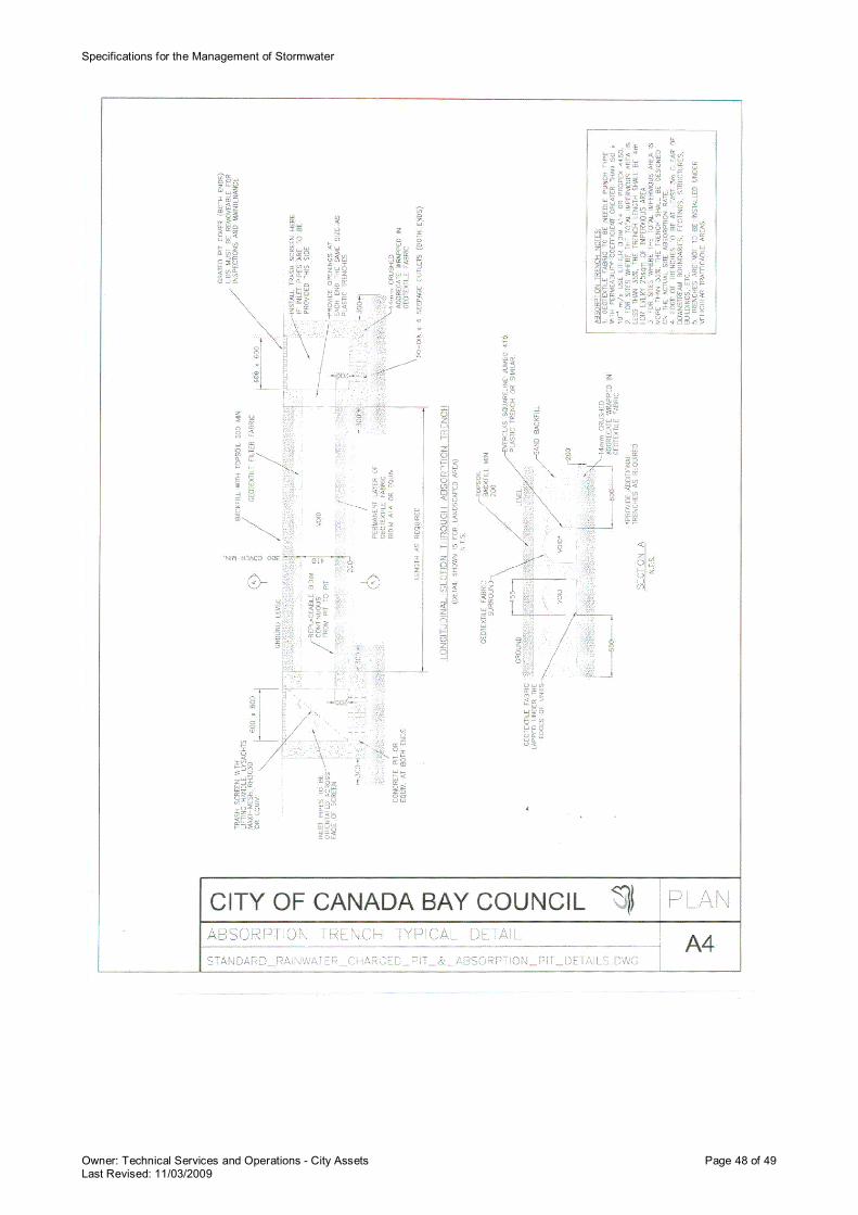
Specifications for the Management of Stormwater
Owner: Technical Services and Operations - City Assets Page 48 of 49Last Revised: 11/03/2009

Specifications for the Management of Stormwater
Owner: Technical Services and Operations - City Assets Page 49 of 49Last Revised: 11/03/2009
1a Marlborough Street, Drummoyne NSW 2047
Tel 9911 6555 Fax 9911 6550 www.canadabay.nsw.gov.au