bioretention - chesapeake stormwater...
TRANSCRIPT
VA DCR STORMWATER DESIGN SPECIFICATION NO. 9 BIORETENTION
Version 2.0, January 1, 2013 Page 1 of 59
VIRGINIA DCR STORMWATER
DESIGN SPECIFICATION No. 9
BIORETENTION
VERSION 2.0
January 1, 2013
SECTION 1: DESCRIPTION
Individual bioretention areas can serve highly impervious drainage areas less than two (2) acres
in size. Surface runoff is directed into a shallow landscaped depression that incorporates many of
the pollutant removal mechanisms that operate in forested ecosystems. The primary component
of a bioretention practice is the filter bed, which has a mixture of sand, soil, and organic material
as the filtering media with a surface mulch layer. During storms, runoff temporarily ponds 6 to
12 inches above the mulch layer and then rapidly filters through the bed. Normally, the filtered
runoff is collected in an underdrain and returned to the storm drain system. The underdrain
consists of a perforated pipe in a gravel layer installed along the bottom of the filter bed. A
bioretention facility with an underdrain system is commonly referred to as a Bioretention Filter.
Bioretention can also be designed to infiltrate runoff into native soils. This can be done at sites
with permeable soils, a low groundwater table, and a low risk of groundwater contamination.
This design features the use of a “partial exfiltration” system that promotes greater groundwater
recharge. Underdrains are only installed beneath a portion of the filter bed, above a stone “sump”
layer, or eliminated altogether, thereby increasing stormwater infiltration. A bioretention facility
without an underdrain system, or with a storage sump in the bottom is commonly referred to as a
Bioretention Basin.
VA DCR STORMWATER DESIGN SPECIFICATION NO. 9 BIORETENTION
Version 2.0, January 1, 2013 Page 2 of 59
Small-scale or Micro-Bioretention used on an individual residential lot is commonly referred to
as a Rain Garden.
SECTION 2: PERFORMANCE
Bioretention creates a good environment for runoff reduction, filtration, biological uptake, and
microbial activity, and provides high pollutant removal. Bioretention can become an attractive
landscaping feature with high amenity value and community acceptance. The overall stormwater
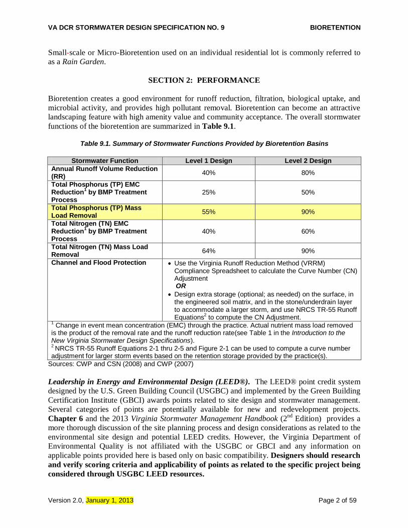
functions of the bioretention are summarized in Table 9.1.
Table 9.1. Summary of Stormwater Functions Provided by Bioretention Basins
Stormwater Function Level 1 Design Level 2 Design
Annual Runoff Volume Reduction (RR)
40% 80%
Total Phosphorus (TP) EMC Reduction
1 by BMP Treatment
Process 25% 50%
Total Phosphorus (TP) Mass Load Removal
55% 90%
Total Nitrogen (TN) EMC Reduction
1 by BMP Treatment
Process 40% 60%
Total Nitrogen (TN) Mass Load Removal
64% 90%
Channel and Flood Protection Use the Virginia Runoff Reduction Method (VRRM) Compliance Spreadsheet to calculate the Curve Number (CN) Adjustment
OR
Design extra storage (optional; as needed) on the surface, in the engineered soil matrix, and in the stone/underdrain layer to accommodate a larger storm, and use NRCS TR-55 Runoff Equations
2 to compute the CN Adjustment.
1 Change in event mean concentration (EMC) through the practice. Actual nutrient mass load removed
is the product of the removal rate and the runoff reduction rate(see Table 1 in the Introduction to the New Virginia Stormwater Design Specifications). 2 NRCS TR-55 Runoff Equations 2-1 thru 2-5 and Figure 2-1 can be used to compute a curve number
adjustment for larger storm events based on the retention storage provided by the practice(s).
Sources: CWP and CSN (2008) and CWP (2007)
Leadership in Energy and Environmental Design (LEED®). The LEED® point credit system
designed by the U.S. Green Building Council (USGBC) and implemented by the Green Building
Certification Institute (GBCI) awards points related to site design and stormwater management.
Several categories of points are potentially available for new and redevelopment projects.
Chapter 6 and the 2013 Virginia Stormwater Management Handbook (2nd
Edition) provides a
more thorough discussion of the site planning process and design considerations as related to the
environmental site design and potential LEED credits. However, the Virginia Department of
Environmental Quality is not affiliated with the USGBC or GBCI and any information on
applicable points provided here is based only on basic compatibility. Designers should research
and verify scoring criteria and applicability of points as related to the specific project being
considered through USGBC LEED resources.

VA DCR STORMWATER DESIGN SPECIFICATION NO. 9 BIORETENTION
Version 2.0, January 1, 2013 Page 3 of 59
Table 9.2. Potential LEED® Credits for Bioretention
1
Credit Category Credit
No. Credit Description
Sustainable Sites SS5.1 Site Development: Protect or Restore Habitat
Sustainable Sites SS5.2 Site Development: Maximize Open Space
Sustainable Sites SS6.1 Stormwater Design: Quantity Control
Sustainable Sites SS6.2 Stormwater Design: Quality Control
Water Efficiency WE1.1 Water Efficient Landscaping: Reduce by 50%
Water Efficiency WE1.2 Water Efficient Landscaping: No Potable Water Use or No Irrigation 1 Actual site design and/or BMP configuration may not qualify for the credits listed. Alternatively, the
project may actually qualify for credits not listed here. Designers should consult with a qualified individual (LEED AP) to verify credit applicability.
SECTION 3: DESIGN TABLES
The most important design factor to consider when applying bioretention to development sites is
the scale at which it will be applied, as follows:
Micro-Bioretention or Rain Gardens. These are small, distributed practices designed to treat
runoff from small areas, such as individual rooftops, driveways and other on-lot features in
single-family detached residential developments. Inflow is typically sheet flow, or can be
concentrated flow with energy dissipation, when located at downspouts.
Bioretention Basins. These are structures treating parking lots and/or commercial rooftops,
usually in commercial or institutional areas. Inflow can be either sheet flow or concentrated flow.
Bioretention basins may also be distributed throughout a residential subdivision, but ideally they
should be located in common area or within drainage easements, to treat a combination of
roadway and lot runoff.
Urban Bioretention. These are structures such as expanded tree pits, curb extensions, and
foundation planters located in ultra-urban developed areas such as city streetscapes. Please refer
to Appendix 9-A of this specification for design criteria for Urban Bioretention.
The major design goal for bioretention is to maximize runoff volume reduction and nutrient
removal. To this end, designers may choose to go with the baseline design (Level 1) or choose an
enhanced design (Level 2) that maximizes nutrient and runoff reduction. If soil conditions
require an underdrain, bioretention areas can still qualify for the Level 2 design if they contain a
stone storage layer beneath the invert of the underdrain.
Both stormwater quality and quantity credits are accounted for in the Virginia Runoff Reduction
Method (VRRM) compliance spreadsheet. The water quality credit represents an annual load
reduction as a combination of the annual reduction of runoff volume (40% and 80% from Level
1 and Level 2 designs, respectively) and the reduction in the pollutant event mean concentration
(EMC) (25% and 50% from Level 1 & 2 designs, respectively).

VA DCR STORMWATER DESIGN SPECIFICATION NO. 9 BIORETENTION
Version 2.0, January 1, 2013 Page 4 of 59
Figure 9.1. Typical Bioretention Filters
To compute the water quantity reduction for larger storm events, the designer can similarly use
the VRRM Compliance spreadsheet or, as an option, the designer may choose to compute the
adjusted curve number associated with the retention storage using the TR-55 Runoff Equations,
as noted in Table 9.1. The adjusted curve number is then used to compute the peak discharge for
the required design storms.
Tables 9.3 and 9.4 below outline the Level 1 and 2 design guidelines for the two scales of
bioretention design.
VA DCR STORMWATER DESIGN SPECIFICATION NO. 9 BIORETENTION
Version 2.0, January 1, 2013 Page 5 of 59
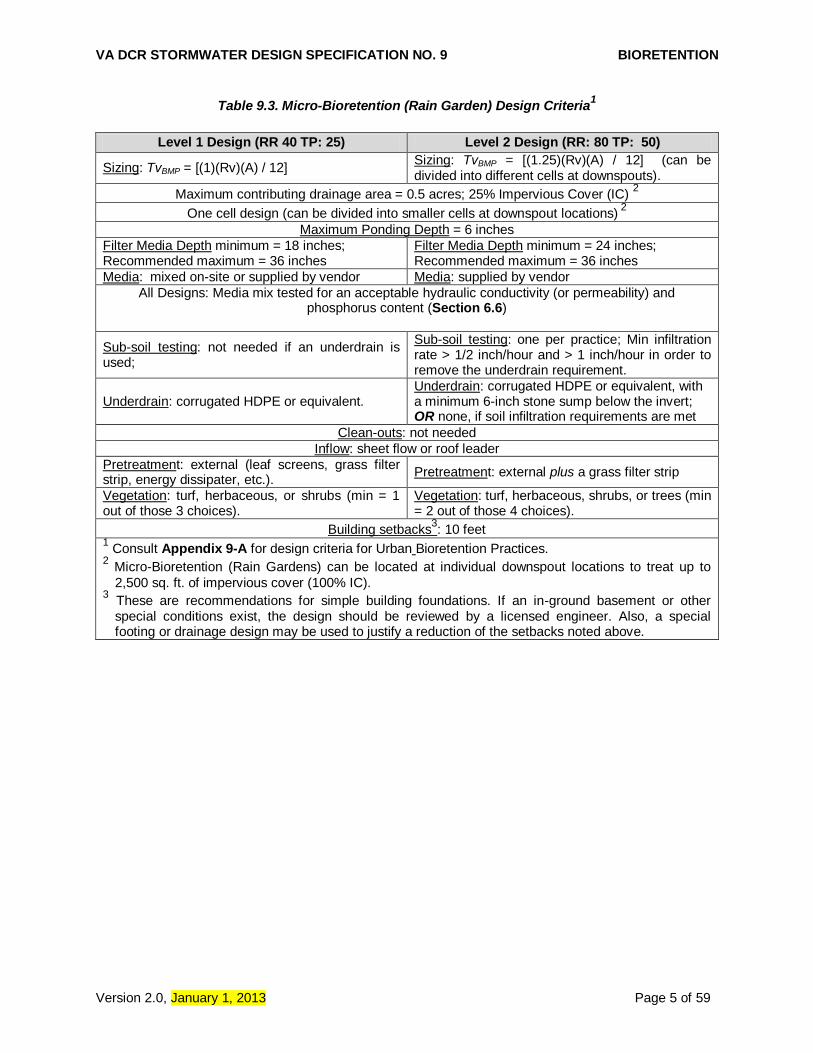
Table 9.3. Micro-Bioretention (Rain Garden) Design Criteria1
Level 1 Design (RR 40 TP: 25) Level 2 Design (RR: 80 TP: 50)
Sizing: TvBMP = [(1)(Rv)(A) / 12] Sizing: TvBMP = [(1.25)(Rv)(A) / 12] (can be divided into different cells at downspouts).
Maximum contributing drainage area = 0.5 acres; 25% Impervious Cover (IC) 2
One cell design (can be divided into smaller cells at downspout locations) 2
Maximum Ponding Depth = 6 inches
Filter Media Depth minimum = 18 inches; Recommended maximum = 36 inches
Filter Media Depth minimum = 24 inches; Recommended maximum = 36 inches
Media: mixed on-site or supplied by vendor Media: supplied by vendor
All Designs: Media mix tested for an acceptable hydraulic conductivity (or permeability) and phosphorus content (Section 6.6)
Sub-soil testing: not needed if an underdrain is used;
Sub-soil testing: one per practice; Min infiltration rate > 1/2 inch/hour and > 1 inch/hour in order to remove the underdrain requirement.
Underdrain: corrugated HDPE or equivalent. Underdrain: corrugated HDPE or equivalent, with a minimum 6-inch stone sump below the invert; OR none, if soil infiltration requirements are met
Clean-outs: not needed
Inflow: sheet flow or roof leader
Pretreatment: external (leaf screens, grass filter strip, energy dissipater, etc.).
Pretreatment: external plus a grass filter strip
Vegetation: turf, herbaceous, or shrubs (min = 1 out of those 3 choices).
Vegetation: turf, herbaceous, shrubs, or trees (min = 2 out of those 4 choices).
Building setbacks3: 10 feet
1 Consult Appendix 9-A for design criteria for Urban Bioretention Practices.
2 Micro-Bioretention (Rain Gardens) can be located at individual downspout locations to treat up to
2,500 sq. ft. of impervious cover (100% IC). 3 These are recommendations for simple building foundations. If an in-ground basement or other
special conditions exist, the design should be reviewed by a licensed engineer. Also, a special footing or drainage design may be used to justify a reduction of the setbacks noted above.

VA DCR STORMWATER DESIGN SPECIFICATION NO. 9 BIORETENTION
Version 2.0, January 1, 2013 Page 6 of 59
Table 9.4. Bioretention Filter and Basin Design Criteria
Level 1 Design (RR 40 TP: 25 ) Level 2 Design (RR: 80 TP: 50)
Sizing (Section 6.1): TvBMP = [(1)(Rv)(A) / 12] + any remaining volume from upstream BMP
Surface Area (sq. ft.) = TvBMP / Storage Depth 1
Sizing (Section 6.1): TvBMP = [(1.25)(Rv)(A) / 12] + any remaining volume from upstream BMP
Surface Area (sq. ft.) = TvBMP /Storage Depth 1
Recommended maximum contributing drainage area = 2.5 acres, or with local approval up to 5 acres and a maximum of 50% impervious
Maximum Ponding Depth = 6 to 12 inches 2 Maximum Ponding Depth = 6 to 12 inches
2
Filter Media Depth minimum = 24 inches; recommended maximum = 48 inches
Filter Media Depth minimum = 36 inches; recommended maximum = 48 inches
Media & Surface Cover (Section 6.6) = supplied by vendor; tested for acceptable hydraulic conductivity (or permeability) and phosphorus content
Sub-soil Testing (Section 6.2): not needed if an underdrain used; Min infiltration rate > 1/2 inch/hour in order to remove the underdrain requirement.
Sub-soil Testing (Section 6.2): one soil profile and two infiltration tests per facility (up to 2,500 ft
2
of filter surface); Min infiltration rate > 1/2 inch/hour in order to remove the underdrain requirement.
Underdrain (Section 6.7) = Schedule 40 PVC with clean-outs
Underdrain & Underground Storage Layer (Section 6.7) = Schedule 40 PVC with clean outs, and a minimum 12-inch stone sump below the invert; OR, none, if soil infiltration requirements are met (Section 6.2)
Inflow: sheet flow, curb cuts, trench drains, concentrated flow, or the equivalent Geometry (Section 6.3): Length of shortest flow path/Overall length = 0.3; OR, other design methods used to prevent short-circuiting; a one-cell design (not including the pre-treatment cell).
Geometry (Section 6.3): Length of shortest flow path/Overall length = 0.8; OR, other design methods used to prevent short-circuiting; a two-cell design (not including the pretreatment cell).
Pre-treatment (Section 6.4): a pretreatment cell, grass filter strip, gravel diaphragm, gravel flow spreader, or another approved (manufactured) pre-treatment structure.
Pre-treatment (Section 6.4): a pretreatment cell plus one of the following: a grass filter strip, gravel diaphragm, gravel flow spreader, or another approved (manufactured) pre-treatment structure.
Conveyance & Overflow (Section 6.5) Conveyance & Overflow (Section 6.5)
Planting Plan (Section 6.8): a planting template to include turf, herbaceous vegetation, shrubs, and/or trees to achieve surface area coverage of at least 75% within 2 years.
Planting Plan (Section 6.8): a planting template to include turf, herbaceous vegetation, shrubs, and/or trees to achieve surface area coverage of at least 90% within 2 years. If using turf, must combine with other types of vegetation.
Building Setbacks 3 (Section 5):
10 feet if down-gradient from building or level (coastal plain); 50 feet if up-gradient. (Refer to additional setback criteria in Section 5)
Deeded Maintenance O&M Plan (Section 8) 1
Storage depth is the sum of the porosity ( ) of the soil media and gravel layers multiplied by their respective depths, plus the surface ponding depth. (Section 6.1). 2 A ponding depth of 6 inches is preferred. Ponding depths greater than 6 inches will require a specific
planting plan to ensure appropriate plant selection (Section 6.8). 3 These are recommendations for simple building foundations. If an in-ground basement or other
special conditions exist, the design should be reviewed by a licensed engineer. Also, a special footing or drainage design may be used to justify a reduction of the setbacks noted above.

VA DCR STORMWATER DESIGN SPECIFICATION NO. 9 BIORETENTION
Version 2.0, January 1, 2013 Page 7 of 59
SECTION 3: TYPICAL DETAILS
Figures 9.2 through 9.5 provide some typical details for several bioretention configurations.
Also see additional details in Appendix 9-B of this design specification.
Figure 9.2. Rain Garden (Micro Bioretention): (a) Simple Disconnection to downstream Rain Garden; (b) Disconnection
Alternate Practice: Compost Amended Filter Path to downstream Rain Garden

VA DCR STORMWATER DESIGN SPECIFICATION NO. 9 BIORETENTION
Version 2.0, January 1, 2013 Page 8 of 59
Figure 9.3. Typical Micro-Bioretention Basin (Rain Garden) Level 1 and Level 2

VA DCR STORMWATER DESIGN SPECIFICATION NO. 9 BIORETENTION
Version 2.0, January 1, 2013 Page 9 of 59
Figure 9.4a: Typical Bioretention Basin Level 1
Figure 9.4b: Typical Bioretention Basin Level 2: Infiltration

VA DCR STORMWATER DESIGN SPECIFICATION NO. 9 BIORETENTION
Version 2.0, January 1, 2013 Page 10 of 59
Figure 9.4c: Typical Bioretention Basin Level 2: Infiltration Sump
Figure 9.4d: Typical Bioretention Level 2: Infiltration Sump with “Upturned Elbow” or Weir

VA DCR STORMWATER DESIGN SPECIFICATION NO. 9 BIORETENTION
Version 2.0, January 1, 2013 Page 11 of 59
Figure 9.5. Typical Detail of Bioretention with Additional Surface Ponding

VA DCR STORMWATER DESIGN SPECIFICATION NO. 9 BIORETENTION
Version 2.0, January 1, 2013 Page 12 of 59
Figure 9.6. Typical Detail of a Bioretention Basin within the Upper Shelf of an ED Pond

VA DCR STORMWATER DESIGN SPECIFICATION NO. 9 BIORETENTION
Version 2.0, January 1, 2013 Page 13 of 59
Figure 9.7a. Pretreatment I – Grass Filter for Sheet Flow
Figure 9.7b. Pretreatment II – Grass Filter for Sheet Flow
Figure 9.8. Pretreatment – Gravel Diaphragm for Sheet Flow from Impervious or Pervious
VA DCR STORMWATER DESIGN SPECIFICATION NO. 9 BIORETENTION
Version 2.0, January 1, 2013 Page 14 of 59
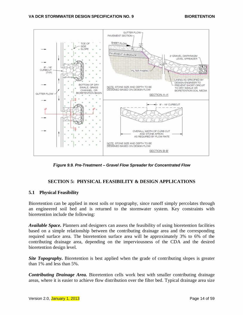
Figure 9.9. Pre-Treatment – Gravel Flow Spreader for Concentrated Flow
SECTION 5: PHYSICAL FEASIBILITY & DESIGN APPLICATIONS
5.1 Physical Feasibility
Bioretention can be applied in most soils or topography, since runoff simply percolates through
an engineered soil bed and is returned to the stormwater system. Key constraints with
bioretention include the following:
Available Space. Planners and designers can assess the feasibility of using bioretention facilities
based on a simple relationship between the contributing drainage area and the corresponding
required surface area. The bioretention surface area will be approximately 3% to 6% of the
contributing drainage area, depending on the imperviousness of the CDA and the desired
bioretention design level.
Site Topography. Bioretention is best applied when the grade of contributing slopes is greater
than 1% and less than 5%.
Contributing Drainage Area. Bioretention cells work best with smaller contributing drainage
areas, where it is easier to achieve flow distribution over the filter bed. Typical drainage area size
VA DCR STORMWATER DESIGN SPECIFICATION NO. 9 BIORETENTION
Version 2.0, January 1, 2013 Page 15 of 59
can range from 0.1 to 2.5 acres and consist of up to 100% impervious cover. Three scales of
bioretention are defined in this specification: (1) micro-bioretention or Rain Gardens (up to 0.5
acre contributing drainage area); (2) bioretention basins (up to 2.5 acres of contributing drainage
area); and (3) Urban Bioretention (Appendix 9-A). Each of these has different design
requirements (refer to Tables 9.3 and 9.4 above). The maximum recommended drainage area to
a single bioretention basin or single cell of a bioretention basin is 2.5 acres. There are successful
examples of bioretention basins treating up to 5 acres; however, the drainage areas are not
entirely impervious. Therefore, if approved by the plan approving authority, the drainage area to
a single bioretention basin can be increased to a maximum of 5 acres provided that the
contributing impervious cover is limited to 2.5 acres (50% impervious cover), and the design
elements intended to address the peak rate and energy of the inflow, such as forebay, energy
dissipaters, high flow diversions, etc., are designed for the expected flows. In such cases, the
bioretention facility should be located within the drainage area so as to capture the Treatment
Volume (Tv) equally from the entire contributing area, and not fill the entire volume from the
immediately adjacent area, thereby bypassing the runoff from the more remote portions of the
site.
Available Hydraulic Head. Bioretention is fundamentally constrained by the invert elevation of
the downstream conveyance system to which the practice discharges (i.e., the bottom elevation
needed to tie the underdrain from the bioretention area into the storm drain system). In general, 4
to 5 feet of elevation above this invert is needed to create the hydraulic head needed to drive
stormwater through a proposed bioretention filter bed. Less hydraulic head is needed if the
underlying soils are permeable enough to dispense with the underdrain.
Water Table. Bioretention should always be separated from the water table to ensure that
groundwater does not intersect the filter bed. Mixing can lead to possible groundwater
contamination or failure of the bioretention facility. A separation distance of 2 feet is
recommended between the bottom of the excavated bioretention area and the seasonally high
ground water table. The separation distance may be reduced to 12 inches in coastal plain
residential settings (Refer to Section 7.2 – Regional Adaptations).
Utilities. Designers should ensure that future tree canopy growth in the bioretention area will not
interfere with existing overhead utility lines. Interference with underground utilities should also
be avoided, particularly water and sewer lines. Local utility design guidance should be consulted
in order to determine the horizontal and vertical clearance required between stormwater
infrastructure and other dry and wet utility lines.
Soils. Soil conditions do not constrain the use of bioretention, although they determine whether
an underdrain is needed. Impermeable soils such as those in Hydrologic Soil Group (HSG) C or
D usually require an underdrain, whereas HSG A and some B soils generally do not. When
designing a bioretention practice, designers must verify soil permeability by using the on-site soil
investigation methods provided in Appendix 8-A of Stormwater Design Specification No. 8
(Infiltration).
Hotspot Land Uses. Runoff from hotspot land uses should not be treated with infiltrating
bioretention (i.e., constructed without an underdrain). For a list of potential stormwater hotspots,
VA DCR STORMWATER DESIGN SPECIFICATION NO. 9 BIORETENTION
Version 2.0, January 1, 2013 Page 16 of 59
please consult Section 10.1 of Stormwater Design Specification No. 8 (Infiltration). An
impermeable bottom liner and an underdrain system must be employed when bioretention is used
to receive and treat hotspot runoff.
Floodplains. Bioretention areas should be constructed outside the limits of the ultimate 100-year
floodplain.
Avoidance of Irrigation or Baseflow. The planned bioretention area should not receive
baseflow, irrigation water, chlorinated wash-water or other such non-stormwater flows that are
not stormwater runoff.
Setbacks. To avoid seepage and frost heave concerns, bioretention areas should not be
hydraulically connected to structure foundations or pavement. Setbacks to structures and roads
vary based on the scale of the bioretention design (see Tables 9.2 and 9.3 above). Expected
effluent concentrations of typical urban runoff (TP, TN, metals) from bioretention basins are
reported by the International BMP Database and are considered to be acceptable in terms of
groundwater impacts, provided that the feasibility factors of water table, hotspot land uses, and
karst (Section 7) are met. However, if ground-water contamination is a concern, it is
recommended that ground-water mapping be conducted to determine possible connections to
adjacent ground-water wells. Otherwise, it is recommended that, at a minimum, bioretention
basins be located a horizontal distance of 50 feet from any water supply well, 35 feet from septic
system drainfields (20 feet if the bioretention filter is lined), and at least 5 feet from down-
gradient wet utility lines. Dry utility lines such as gas, electric, cable and telephone may cross
under bioretention areas if they are protected in accordance with the particular utility
requirements and can be routinely accessed without disturbing the bioretention basin.
5.2 Potential Bioretention Applications
Bioretention can be used wherever water can be conveyed to a surface area. Bioretention has
been used at commercial, institutional, and residential sites in spaces that are traditionally
pervious and landscaped. It should be noted that special care must be taken to provide adequate
pre-treatment for bioretention cells in space-constrained high traffic areas. Typical locations for
bioretention include the following:
Parking lot islands. The parking lot grading is designed for sheet flow towards linear
landscaping areas and parking islands between rows of spaces. Curb-less pavement edges can be
used to convey water into a depressed island landscaping area. Curb cuts can also be used for this
purpose, but they are more prone to blockage, clogging and erosion.
Parking lot edge. Small parking lots can be graded so that flows reach a curb-less pavement
edge or curb cut before reaching catch basins or storm drain inlets. The turf at the edge of the
parking lot functions as a filter strip to provide pre-treatment for the bioretention practice. The
depression for bioretention is located in the pervious area adjacent to the parking lot.

VA DCR STORMWATER DESIGN SPECIFICATION NO. 9 BIORETENTION
Version 2.0, January 1, 2013 Page 17 of 59
Road medians, roundabouts, interchanges and cul-de-sacs. The road cross-section is designed
to slope towards the center median or center island rather than the outer edge, using a curb-less
edge.
Right-of-way or commercial setback. A linear configuration can be used to convey runoff in
sheet flow from the roadway, or a grass channel or pipe may convey flows to the bioretention
practice.
Courtyards. Runoff collected in a storm drain system or roof leaders can be directed to
courtyards or other pervious areas on site where bioretention can be installed.
Individual residential lots. Roof leaders can be directed to small bioretention areas, often called
“rain gardens,” located at the front, side, or rear of a home in a drainage easement. For smaller
lots, the front yard bioretention corridor design may be preferable (See Stormwater Design
Specification No. 1: Rooftop Disconnection).
Unused pervious areas on a site. Storm flows can be redirected from a storm drain pipe to
discharge into a bioretention area.
Dry Extended Detention (ED) basin. A bioretention cell can be located on an upper shelf of an
extended detention basin, after the pre-treatment forebay, in order to boost treatment. Depending
on the ED basin design, the designer may choose to locate the bioretention cell in the bottom of
the basin. However, the design must carefully account for the potentially deeper ponding depths
(greater than 6 or 12 inches) associated with extended detention.
Retrofitting. Numerous options are available to retrofit bioretention in the urban landscape, as
described in Profile Sheet ST-4 of Schueler et al (2007).
SECTION 6: DESIGN CRITERIA
6.1. Sizing of Bioretention Practices
6.1.1 Stormwater Quality
Sizing of the surface area (SA) for bioretention practices is based on the computed BMP design
Treatment Volume, TvBMP. The TvBMP is the treatment volume based on the contributing drainage
area to the BMP, TvDA, plus any remaining runoff volume discharged from upstream BMPs in
the treatment train. The required surface area (in square feet) is computed as the TvBMP (in cubic
feet) divided by the equivalent storage depth (in feet). The equivalent storage depth is computed
as the depth of media, gravel, or surface ponding (in feet) multiplied by the accepted porosity.
Therefore, the designer can influence the required surface area by adjusting the depth of each
material layer (within the required minimums and maximums of Table 9.3).
The accepted porosity ( ) for each of the materials is as follows (see Figure 9.10 below):

VA DCR STORMWATER DESIGN SPECIFICATION NO. 9 BIORETENTION
Version 2.0, January 1, 2013 Page 18 of 59
Bioretention Soil Media = 0.25
Gravel = 0.40
Surface Storage = 1.0
The equivalent storage depth for Level 1 with a 6-inch surface ponding depth, a 24-inch soil
media depth, and a 12-inch gravel layer is therefore computed as:
Equation 9.1. Bioretention Level 1 Design Storage Depth
(2 ft. x 0.25) + (1 ft. x 0.40) + (0.5 x 1.0) = 1.40 ft.
And the equivalent storage depth for Level 2 with a 6-inch surface ponding depth, a 36-inch soil
media depth, and a 12-inch gravel layer is computed as:
Equation 9.2. Bioretention Level 2 Design Storage Depth
(3 ft. x 0.25) + (1 ft. x 0.40) + (0.5 x 1.0) = 1.65 ft
Figure 9.10. Typical Bioretention Section with Porosity for Volume Computations
Therefore, the Level 1 bioretention surface area (SA) is computed as:
Equation 9.3. Bioretention Level 1 Design Surface Area
SA (sq. ft.) = TvBMP / 1.40 ft.
And the Level 2 bioretention surface area is computed as:

VA DCR STORMWATER DESIGN SPECIFICATION NO. 9 BIORETENTION
Version 2.0, January 1, 2013 Page 19 of 59
Equation 9.4. Bioretention Level 2 Design Surface Area
SA (sq. ft.) = (TvBMP) / 1.65 ft.
Where:
SA = Minimum surface area of bioretention filter (sq. ft.)
TvBMP = Level 1 BMP design treatment volume (cu. ft.) = [(1.0 in.)(Rv)(A) / 12]; or
= Level 2 BMP design treatment volume (cu. ft.) = 1.25[(1.0 in.)(Rv)(A) / 12]
(NOTE: Rv = the composite volumetric runoff coefficient from the VRRM Compliance
Spreadsheet, or Chapter 11 of the Virginia Stormwater Management
Handbook, 2nd
Edition.)
Equations 9.1 through 9.4 should be modified if the storage depths of the soil media, gravel layer, or ponded water vary in the actual design or with the addition of any surface or subsurface storage components (e.g., additional area of surface ponding, subsurface storage chambers, etc.).
NOTE: The infiltration rate of the soils must be verified at a minimum of 0.5
inches per hour in order for the volume infiltration sump to be counted towards
the storage volume. Refer to Section 6.7 below or Figure 9.4c above for
information on implementing an “upturned elbow” configuration to create the
infiltration sump. If the field-verified infiltration rate is less than 0.5 inches per
hour, the sump will still qualify as a Level 2 design. However, any additional
storage needed must be added above the sump through additional stone, media, or
surface ponding.
6.1.2 Stormwater Quantity
The water quality Tv can be counted as part of the Channel Protection Volume or Overbank
Flood Protection Volume to satisfy stormwater quantity control requirements. In addition,
designers may be able to create additional surface storage by expanding the surface ponding
footprint in order to accommodate a greater quantity credit for channel and/or flood protection,
without necessarily increasing the soil media footprint. In other words, the engineered soil media
would only underlay part of the surface area of the bioretention (see Figure 9.10 above).
In this regard, the ponding footprint can be increased as follows to allow for additional storage:
50% surface area increase if the ponding depth is 6 inches or less.
25% surface area increase if the ponding depth is between 6 and 12 inches.
These values may be modified as additional data on the long term permeability of bioretention
filters becomes available.
6.2. Soil Infiltration Rate Testing
VA DCR STORMWATER DESIGN SPECIFICATION NO. 9 BIORETENTION
Version 2.0, January 1, 2013 Page 20 of 59
In order to determine if an underdrain will be needed, one must measure the infiltration rate of
subsoils at the invert elevation of the bioretention area, as noted in the soil testing requirements
for each scale of bioretention, in Design Tables 9.3 and 9.4 above. The infiltration rate of
subsoils must exceed 1 inch per hour in order to dispense with the underdrain requirement for
Rain Gardens (micro-bioretention), and 1/2 inch per hour for bioretention basins. On-site soil
infiltration rate testing requirements and procedures are outlined in Appendix 8-A of
Stormwater Design Specification No. 8 (Infiltration). Soil testing is not needed for Level 1
bioretention areas, where an underdrain is used.
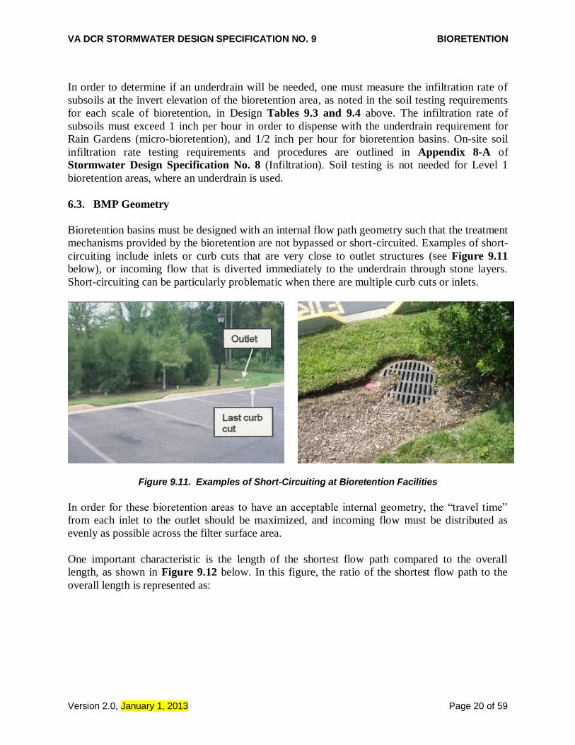
6.3. BMP Geometry
Bioretention basins must be designed with an internal flow path geometry such that the treatment
mechanisms provided by the bioretention are not bypassed or short-circuited. Examples of short-
circuiting include inlets or curb cuts that are very close to outlet structures (see Figure 9.11
below), or incoming flow that is diverted immediately to the underdrain through stone layers.
Short-circuiting can be particularly problematic when there are multiple curb cuts or inlets.
Figure 9.11. Examples of Short-Circuiting at Bioretention Facilities
In order for these bioretention areas to have an acceptable internal geometry, the “travel time”
from each inlet to the outlet should be maximized, and incoming flow must be distributed as
evenly as possible across the filter surface area.
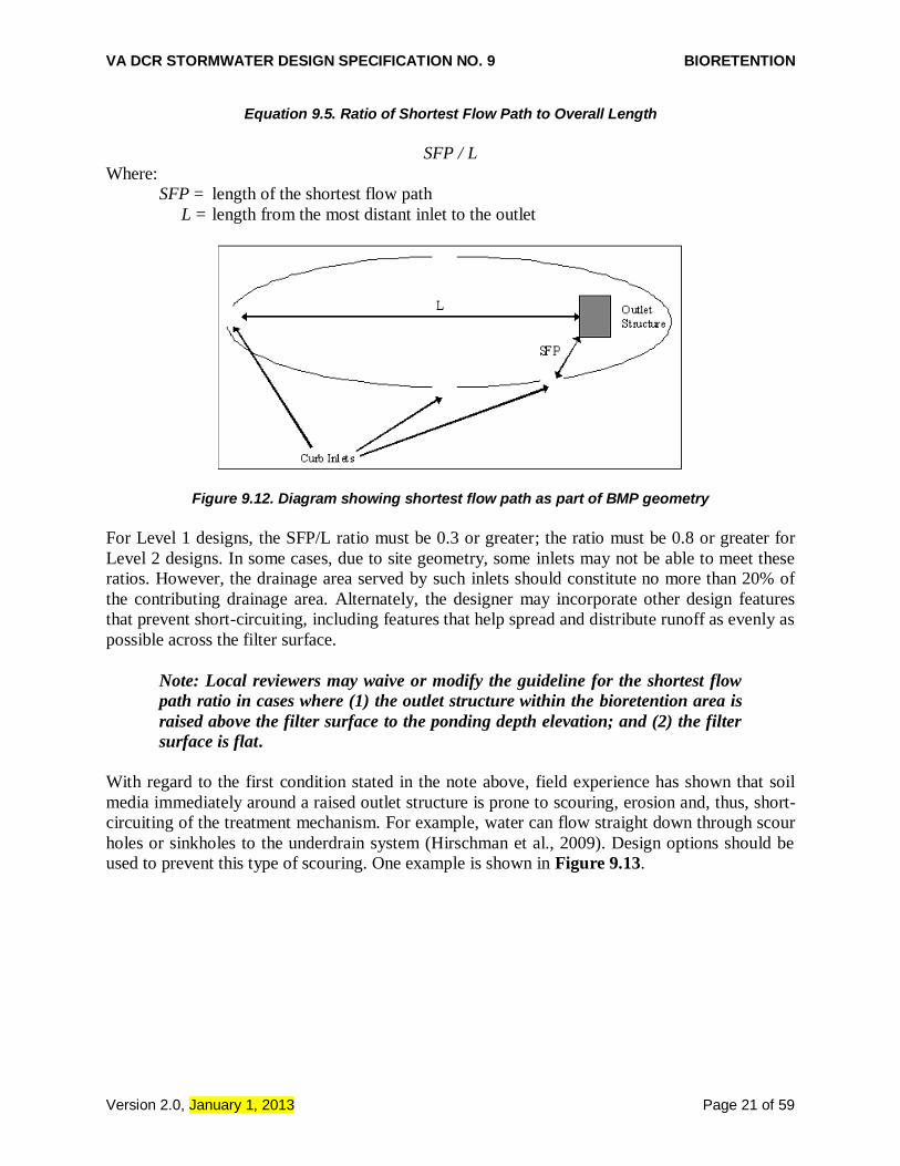
One important characteristic is the length of the shortest flow path compared to the overall
length, as shown in Figure 9.12 below. In this figure, the ratio of the shortest flow path to the
overall length is represented as:
VA DCR STORMWATER DESIGN SPECIFICATION NO. 9 BIORETENTION
Version 2.0, January 1, 2013 Page 21 of 59
Equation 9.5. Ratio of Shortest Flow Path to Overall Length
SFP / L
Where:
SFP = length of the shortest flow path
L = length from the most distant inlet to the outlet
Figure 9.12. Diagram showing shortest flow path as part of BMP geometry
For Level 1 designs, the SFP/L ratio must be 0.3 or greater; the ratio must be 0.8 or greater for
Level 2 designs. In some cases, due to site geometry, some inlets may not be able to meet these
ratios. However, the drainage area served by such inlets should constitute no more than 20% of
the contributing drainage area. Alternately, the designer may incorporate other design features
that prevent short-circuiting, including features that help spread and distribute runoff as evenly as
possible across the filter surface.
Note: Local reviewers may waive or modify the guideline for the shortest flow
path ratio in cases where (1) the outlet structure within the bioretention area is
raised above the filter surface to the ponding depth elevation; and (2) the filter
surface is flat.
With regard to the first condition stated in the note above, field experience has shown that soil
media immediately around a raised outlet structure is prone to scouring, erosion and, thus, short-
circuiting of the treatment mechanism. For example, water can flow straight down through scour
holes or sinkholes to the underdrain system (Hirschman et al., 2009). Design options should be
used to prevent this type of scouring. One example is shown in Figure 9.13.

VA DCR STORMWATER DESIGN SPECIFICATION NO. 9 BIORETENTION
Version 2.0, January 1, 2013 Page 22 of 59
Figure 9.13. Typical Detail of how to prevent bypass
or short-circuiting around the overflow structure
The designer should ensure that incoming flow is spread as evenly as possible across the filter
surface to maximize the treatment potential.
6.4. Pre-treatment
Pre-treatment of runoff entering bioretention areas is necessary to trap coarse sediment particles
before they reach and prematurely clog the filter bed. Pre-treatment measures must be designed
to evenly spread runoff across the entire width of the bioretention area. Several pre-treatment
measures are feasible, depending on the scale of the bioretention practice and whether it receives
sheet flow, shallow concentrated flow or deeper concentrated flows. The following are
appropriate pretreatment options:
For Micro Bioretention (Rain Gardens):
Leaf Screens as part of the gutter system serve to keep the heavy loading of organic debris
from accumulating in the bioretention cell.
Grass Filter Strips (for sheet flow), applied on residential lots, where the lawn area can serve
as a grass filter strip adjacent to a rain garden.
Gravel or Stone Diaphragm (for either sheet flow or concentrated flow); this is a gravel
diaphragm at the end of a downspout or other concentrated inflow point that should run
perpendicular to the flow path to promote settling.

VA DCR STORMWATER DESIGN SPECIFICATION NO. 9 BIORETENTION
Version 2.0, January 1, 2013 Page 23 of 59
For Bioretention Basins:
Pre-treatment Cells (channel flow): Similar to a forebay, this cell is located at piped inlets or
curb cuts leading to the bioretention area and consists of an energy dissipater sized for the
expected rates of discharge. It has a storage volume equivalent to at least 15% of the total Tv
(inclusive) with a 2:1 length-to-width ratio. The cell may be formed by a wooden or stone
check dam or an earthen or rock berm. Pretreatment cells do not need underlying engineered
soil media, in contrast to the main bioretention cell.
Grass Filter Strips (for sheet flow): Grass filter strips extend from the edge of pavement to
the bottom of the bioretention basin at a 5:1 slope or flatter. Alternatively, provide a
combined 5 feet of grass filter strip at a maximum 5% (20:1) slope and 3:1 or flatter side
slopes on the bioretention basin. (See Figure 9.7)
Gravel or Stone Diaphragms (sheet flow). A gravel diaphragm located at the edge of the
pavement should be oriented perpendicular to the flow path to pre-treat lateral runoff, with a
2 to 4 inch drop. The stone must be sized according to the expected rate of discharge. (See
Figure 9.8)
Gravel or Stone Flow Spreaders (concentrated flow). The gravel flow spreader is located at
curb cuts, downspouts, or other concentrated inflow points, and should have a 2 to 4 inch
elevation drop from a hard-edged surface into a gravel or stone diaphragm. The gravel should
extend the entire width of the opening and create a level stone weir at the bottom or treatment
elevation of the basin. (See Figure 9.9)
Innovative or Proprietary Structure: An approved proprietary structure with demonstrated
capability of reducing sediment and hydrocarbons may be used to provide pre-treatment.
Refer to the Virginia BMP Clearinghouse web site (http://www.vwrrc.vt.edu/swc/) for
information on approved proprietary structures.
6.5. Conveyance and Overflow
For on-line bioretention: An overflow structure should always be incorporated into on-line
designs to safely convey larger storms through the bioretention area. The following criteria apply
to overflow structures:
The overflow associated with the 2 and 10 year design storms should be controlled so that
velocities are non-erosive at the outlet point (i.e., to prevent downstream erosion).
Common overflow systems within bioretention practices consist of an inlet structure, where
the top of the structure is placed at the maximum water surface elevation of the bioretention
area, which is typically 6 to 12 inches above the surface of the filter bed (6 inches is the
preferred ponding depth).
The overflow capture device (typically a yard inlet) should be scaled to the application – this
may be a landscape grate inlet or a commercial-type structure.
The filter bed surface should generally be flat so the bioretention area fills up like a bathtub.
For off-line bioretention: Off-line designs are preferred (see Figure 9.14 below for an
example). One common approach is to create an alternate flow path at the inflow point into the
structure such that when the maximum ponding depth is reached, the incoming flow is diverted
past the facility. In this case, the higher flows do not pass over the filter bed and through the
facility, and additional flow is able to enter as the ponding water filtrates through the soil media.

VA DCR STORMWATER DESIGN SPECIFICATION NO. 9 BIORETENTION
Version 2.0, January 1, 2013 Page 24 of 59
Another option is to use a low-flow diversion or flow splitter at the inlet to allow only the Tv to
enter the facility. This may be achieved with a weir or curb opening sized for the target flow, in
combination with a bypass channel. Using a weir or curb opening helps minimize clogging and
reduces the maintenance frequency. (Further guidance on determining the Tv design peak flow
rate will be necessary in order to ensure proper design of the diversion structure.)
6.6. Filter Media and Surface Cover
The filter media and surface cover are the two most important elements of a bioretention
facility in terms of long-term performance. The ultimate performance goals of the combination
of engineered soil mix and surface cover (plants) is to maintain a design infiltration rate and soil
permeability so as to treat the stormwater runoff to remove phosphorus (P) and other nutrients
and contaminants during a wide range of storm intensities and volumes.
Some important definitions to help designers, contractors, and material suppliers achieve these
goals include the following:
Soil infiltration: the rate at which stormwater enters the surface of the soil. Infiltration is
influenced by soil structure, compaction/bulk density, organic matter, moisture content, and
other physical characteristics at the soil surface. The design infiltration rate is usually expressed
as a constant value, but the actual infiltration rate can vary due to differences in depth of ponding
(hydraulic head) or other surface and subsurface soil conditions during the receiving event.
Initial rates of infiltration into dry surface soils can be quite rapid and then will decrease as the
soil wets and/or swells. Assuming constant head conditions, the infiltration rate will equilibrate
after some period of time to approach and reflect the internal permeability (see below) of the
underlying soil mix as described below.
Soil media permeability: the rate at which percolating stormwater flows through the soil after it
has infiltrated.
NOTE: Infiltration and Permeability are used interchangeably in many
reference materials but refer to two different physical processes.
The infiltration and permeability of a given soil are related to the hydraulic conductivity of the
soil (K). The rate at which water enters the soil (infiltration), under optimal conditions, starts
very fast and then declines and eventually approaches a constant rate of entry. This constant rate
of infiltration is sometimes called the soil’s permeability, but is technically defined as the
saturated hydraulic conductivity (Ksat) when it equals or approaches the internal permeability of
the underlying soil medium. In almost all cases, reference to an infiltration rate implies this long-
term constant rate (permeability or Ksat; Jarrett, 2008). For the purpose of bioretention and other
engineered media system design, it is reasonable to assume that the soil media should infiltrate
the stormwater at a rate equal to the long-term Ksat of the underlying soil media mix.
Therefore, the design goal of the soil media is to provide a mixture that has a porosity that will
maintain the desired permeability, while also providing limited soil fines and sufficient organic
matter to support plant growth and adsorb P and other stormwater contaminants. It is expected
that over time, the seasonal cycle of plant growth within the bioretention basin will lead to an

VA DCR STORMWATER DESIGN SPECIFICATION NO. 9 BIORETENTION
Version 2.0, January 1, 2013 Page 25 of 59
adequate accumulation of organic matter to maintain plant growth. The challenge, therefore, is to
provide enough organic matter within the initial soil media mix to support the initial seasons of
plant establishment and growth, while not overloading the system with excessive nutrients or soil
fines (from the organic matter or topsoil) which might cause leaching of nutrients or gradual
clogging of the soil porosity. It is also expected that the organic matter will enhance
aggregation/structure of the media mix over time to aid in maintenance of permeability.
Soil porosity is the fraction of a volume of soil material that is not solid (also referred to as the
void space). As the volume of fines − defined as either clay particles (less than 2 microns, or
0.002 mm) or silt particles (between 2 and 50 microns, or 0.002 and 0.05 mm) − within a given
soil mix is increased, there is a possibility that those fines may migrate or be flushed downward
through the soil mix with each runoff event and eventually fill or otherwise clog the void space
randomly throughout the mix, creating preferential flow paths. In the short term this can lead to
short-circuiting and reduced volume reduction and pollutant removal, and in the long term it can
result in clogging the soil layer. This tendency is offset by the addition and maintenance of
appropriate amounts of soil organic matter, which binds the soil fines into larger non-mobile
aggregates.
General Filter Media Physical Composition. The mineral soil texture of the bioretention soil
mix should be loamy coarse sand with no more than 10% clay and at least 10% but no more
than 20% silt + clay; at least 75% of the sand fraction should be coarse or very coarse sand.
To allow for appropriate Cation Exchange Capacity (CEC) and nutrient removal, the mix
should contain at least 10% soil fines (silt + clay) while meeting the overall texture
specification above. The particle size analysis must be conducted on the mineral fraction only
or after following appropriate treatments to remove organic matter before the particle size
analysis.
The Filter Media should contain 3% to 5% organic matter, as determined by the
conventional Walkley-Black soil organic matter determination method or a similar analysis.
Soil organic matter is expressed on a dry weight basis and does not include coarse particulate
(visible) components.
The overall particle size distribution of the mix will vary since the sand fraction may contain
some finer sizes, as will native topsoils, if used. As stated previously, the goal of the mixture
is to achieve the desired constant head permeability. Therefore, the filter media composition
noted above serves as the target recipe for the three ingredients, while the ultimate
performance goal is to achieve a verified soil permeability or hydraulic conductivity (Ksat)
of 1 to 2 inches per hour (or 30 to 60 cm/day).

VA DCR STORMWATER DESIGN SPECIFICATION NO. 9 BIORETENTION
Version 2.0, January 1, 2013 Page 26 of 59
Figure 9.14. Typical Details for Off-Line Bioretention Basin
The following is the recommended composition of the three media ingredients:
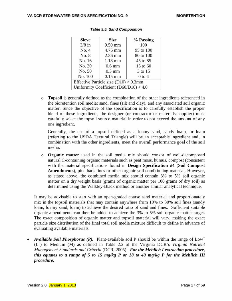
o Sand shall consist of silica based coarse aggregate, angular or round in shape and
meet the mixture grain size distribution below. No substitutions of alternate materials
such as diabase, calcium carbonate, rock dust or dolomitic sands are accepted. In
particular, mica can make up no more than 5% of the total sand fraction. The sand
fraction may also contain a limited amount of particles > 2.0 mm and < 9.5 mm (see
the table below), but the overall sand fraction must meet the specification of >75%
being coarse or very coarse sand.
VA DCR STORMWATER DESIGN SPECIFICATION NO. 9 BIORETENTION
Version 2.0, January 1, 2013 Page 27 of 59
Table 9.5. Sand Composition
Sieve
3/8 in
No. 4
No. 8
No. 16
No. 30
No. 50
No. 100
Size
9.50 mm
4.75 mm
2.36 mm
1.18 mm
0.6 mm
0.3 mm
0.15 mm
% Passing
100
95 to 100
80 to 100
45 to 85
15 to 60
3 to 15
0 to 4
Effective Particle size (D10) > 0.3mm
Uniformity Coefficient (D60/D10) < 4.0
o Topsoil is generally defined as the combination of the other ingredients referenced in
the bioretention soil media: sand, fines (silt and clay), and any associated soil organic
matter. Since the objective of the specification is to carefully establish the proper
blend of these ingredients, the designer (or contractor or materials supplier) must
carefully select the topsoil source material in order to not exceed the amount of any
one ingredient.
Generally, the use of a topsoil defined as a loamy sand, sandy loam, or loam
(referring to the USDA Textural Triangle) will be an acceptable ingredient and, in
combination with the other ingredients, meet the overall performance goal of the soil
media.
o Organic matter used in the soil media mix should consist of well-decomposed
natural C-containing organic materials such as peat moss, humus, compost (consistent
with the material specifications found in Design Specification #4 (Soil Compost
Amendments), pine bark fines or other organic soil conditioning material. However,
as stated above, the combined media mix should contain 3% to 5% soil organic
matter on a dry weight basis (grams of organic matter per 100 grams of dry soil) as
determined using the Walkley-Black method or another similar analytical technique.
It may be advisable to start with an open-graded coarse sand material and proportionately
mix in the topsoil materials that may contain anywhere from 10% to 30% soil fines (sandy
loam, loamy sand, loam) to achieve the desired ratio of sand and fines. Sufficient suitable
organic amendments can then be added to achieve the 3% to 5% soil organic matter target.
The exact composition of organic matter and topsoil material will vary, making the exact
particle size distribution of the final total soil media mixture difficult to define in advance of
evaluating available materials.
Available Soil Phosphorus (P). Plant-available soil P should be within the range of Low+
(L+) to Medium (M) as defined in Table 2.2 of the Virginia DCR’s Virginia Nutrient
Management Standards and Criteria (DCR, 2005). For the Mehlich I extraction procedure,
this equates to a range of 5 to 15 mg/kg P or 18 to 40 mg/kg P for the Mehlich III
procedure.

VA DCR STORMWATER DESIGN SPECIFICATION NO. 9 BIORETENTION
Version 2.0, January 1, 2013 Page 28 of 59
The filter media should contain sufficient plant available P to support initial plant
establishment and plant growth, but not serve as a significant source of P that could result in
long term leaching. The media must also be relatively loose and non-compacted to allow for
adequate inter-connected porosity to meet the required permeability (Ksat) specification.
Saxton et al. (1986) estimated generalized bulk densities and soil-water characteristics from
soil texture assumptions. The expected bulk density of the loamy sand soil composition
described above should be in the range of 1.6 to 1.7 g/cm3.
Cation Exchange Capacity (CEC). The relative ability of soils to hold and retain nutrient
cations like Ca and K is referred to as cation exchange capacity or CEC, measured as the
total amount of positively charged cations that a soil can hold per unit of dry mass. CEC is
also used as an index of overall soil reactivity and is commonly expressed in milliequivalents
per 100 grams (meq/100g) of soil or cmol+/kg (equal values). A soil with a moderate to high
CEC indicates a greater ability to capture and retain positively charged contaminants, which
encourages conditions to remove phosphorus, assuming that soil fines (particularly fine silts
and clays) are at least partially responsible for CEC. The minimum CEC of a bioretention
soil media mix for pollutant removal is 5.0 (meq/100 g or cmol+/kg) or greater. The filter
media CEC should be determined by the Unbuffered Salt, Ammonium Acetate, Summation
of Cations or Effective CEC techniques (Sumner and Miller, 1996) or similar methods that
do not use strongly acidic extracting solutions.
Coatings of Fe- and Al-oxides on mineral soil surfaces are also responsible for significant P
retention and may be present in soils with low CEC. Thus, it is important for filter media P
removal efficiency that some amount of mineral fines (10% - 20%) be present as long as the
texture and permeability specifications cited herein are met. This is important due to the fact
that soil organic matter per se is not active in adsorption of P.
The CEC of the soil is determined in part by the amount of clay and/or humus or organic
matter present. Since the bioretention media is a coarse mineral texture, and since the added
organic matter may not have the relatively high CEC of native humus, it may be difficult to
achieve the ideal CEC for the mixture as a whole in freshly blended materials. However, it is
expected that over time, natural accumulation of organic matter will improve soil reactivity.
Therefore, the initial media mixture may require additional suitable organic matter to
increase the CEC to the extent possible without overly compromising the filter media
composition or elevating the available P.
Filter Media Permeability: The bioretention soil media should have a minimum infiltration
rate of 1 to 2 inches per hour (or 30 to 60 cm/day). (Note: a proper soil mix will have an
initial infiltration rate that is significantly higher.)
Depth. The standard minimum filter bed depth ranges from 24 and 36 inches for Level 1 and
Level 2 designs, respectively, (18 to 24 inches for rain gardens or micro-bioretention). If
trees are included in the bioretention planting plan, tree planting holes in the filter bed must
be at least 4 feet deep to provide enough soil volume for the root structure of mature trees.
Use turf, perennials or shrubs instead of trees to landscape shallower filter beds.

VA DCR STORMWATER DESIGN SPECIFICATION NO. 9 BIORETENTION
Version 2.0, January 1, 2013 Page 29 of 59
Filter Media for Tree Planting Areas. A more organic filter media is recommended within
the planting holes for trees, with a ratio of 50% sand, 30% topsoil and 20% acceptable leaf
compost.
Mulch. A 2- to 3-inch layer of mulch on the surface of the filter bed enhances plant survival,
suppresses weed growth, and pre-treats runoff before it reaches the filter media. Shredded,
aged hardwood bark mulch makes a very good surface cover, as it retains a significant
amount of nitrogen and typically will not float away.
Alternative to Mulch Cover. In some situations, designers may consider alternative surface
covers such as turf, native groundcover, erosion control matting (coir or jute matting), river
stone, or pea gravel. The decision regarding the type of surface cover to use should be based
on function, cost and maintenance. Stone or gravel are not recommended in parking lot
applications, since they increase soil temperature and have low water holding capacity.
Media for Turf Cover. One adaptation is to design the filter media primarily as a sand filter
with organic content only at the top. Leaf compost tilled into the top layers will provide
organic content for the vegetative cover. If grass is the only vegetation, the ratio of compost
may be reduced.
6.7. Underdrain and Underground Storage Layer
Some Level 2 designs will not use an underdrain (where soil infiltration rates meet minimum
standards; see Section 6.2 and Section 3 design tables). For Level 2 designs with an underdrain,
an underground storage layer, referred to as an infiltration sump, of 12 inches should be
incorporated below the invert of the underdrain.
The total depth of the storage layer, including the sump, will depend on the target treatment and
storage volumes needed to meet water quality, channel protection, and/or flood protection
criteria. However, the bottom of the storage layer must be at least 2 feet above the seasonally
high water table. The storage layer should consist of clean, washed #57 stone and, when needed,
an approved infiltration or storage module.
The infiltration sump can consist of a 12-inch stone layer underneath the perforated underdrain
pipe, or as an alternative, the infiltration sump can be created with an “upturned elbow”
configuration on the underdrain. This configuration places the perforated underdrain at the
bottom of the stone reservoir layer, with the outlet elevated to the same elevation as the top of
the sump. Figure 9.4.c illustrates this design variant. The sump will dewater by percolating into
the native soils. A minimum field-verified infiltration rate of ½-inch per hour is required in order
to count the stone reservoir as storage volume.
The underdrain transitions to a solid wall pipe prior to exiting the stone reservoir layer and is
directed towards an outlet manhole or other structure. (This run of pipe should be straight, or
include cleanouts at 45 degree (maximum) horizontal bends, and be set at a minimal grade.) In
order to create the higher outlet elevation, the outlet manhole is configured with an internal weir
wall with the top of the weir set at the same elevation as the top of the stone sump. This is

VA DCR STORMWATER DESIGN SPECIFICATION NO. 9 BIORETENTION
Version 2.0, January 1, 2013 Page 30 of 59
preferred over installing a vertical bend on the outlet pipe that can be difficult to maintain. This
design variant can also include a drain orifice in the bottom of the weir to allow the sump to be
drained if, over time, the exfiltration into the soil becomes restricted. This orifice should be
covered with a plate that is clearly marked to indicate that it remain blocked under normal
operating conditions.
All bioretention basins should include observation wells (Figure 9.b.4 above). The observation
wells should be tied into any T’s or Y’s in the underdrain system, and should extend upwards to
be flush with the surface, with a vented cap.
6.8. Bioretention Planting Plans
A landscaping plan must be provided for each bioretention area. Minimum plan elements shall
include the proposed bioretention template to be used, delineation of planting areas, the planting
plan, including the size, the list of planting stock, sources of plant species, and the planting
sequence, including post-nursery care and initial maintenance requirements. The planting plan
should be prepared by a qualified landscape architect in order to tailor the planting plan to the
site-specific conditions.
Native plant species are preferred over non-native species, but some ornamental species may be
used for landscaping effect if they are not aggressive or invasive. Some popular native species
that work well in bioretention areas and are commercially available can be found in Table 9.6.
Internet links to more detailed bioretention plant lists developed in piedmont and coastal plain
communities of the Chesapeake Bay region are provided in Table 9.7.
The planting template refers to the form and combination of native trees, shrubs, and perennial
ground covers that maintain the appearance and function of the bioretention area. There is a
growing consensus among horticulturists that a diverse herbaceous cover will create a dynamic
ground-plane of native perennials and grasses that, working in concert with the soil, will be more
effective at filtering pollutants than a sparse collection of woody trees or shrubs will be. Where
trees and shrubs are recommended (typically Level 2 designs), the designer should consider the
long term growth of the plants – trees can dominate a facility and require extensive maintenance.
In either case, a diverse mixture will allow plants best suited to the particular wet/dry regime of
the practice’s micro-environment to thrive. This will result in more rigorous growth, greater
pollutant removal performance, and less (or easier) maintenance.
The six most common bioretention templates are as follows:
Turf. This option is typically restricted to on-lot micro-bioretention applications, such as a
front yard rain garden. Grass species should be selected that have dense cover, are relatively
slow growing, and require the least mowing and chemical inputs (e.g., fine fescue, tall
fescue).
Perennial garden. This option uses herbaceous plants and native grasses to create a garden
effect with seasonal cover. It may be employed in both micro-scale and small scale
bioretention applications. This option is attractive, but it requires more maintenance in the
form of weeding.

VA DCR STORMWATER DESIGN SPECIFICATION NO. 9 BIORETENTION
Version 2.0, January 1, 2013 Page 31 of 59
Perennial garden with shrubs. This option provides greater vertical form by mixing native
shrubs and perennials together in the bioretention area. This option is frequently used when
the filter bed is too shallow to support tree roots. Shrubs should have a minimum height of 30
inches.
Tree, shrub and herbaceous plants. This is the traditional landscaping option for
bioretention. It produces the most natural effect, and it is highly recommended for
bioretention basin applications. The landscape goal is to simulate the structure and function
of a native forest plant community.
Turf and tree. This option is a lower maintenance version of the tree-shrub-herbaceous
option 4, where the mulch layer is replaced by turf cover. Trees are planted within larger
mulched islands to prevent damage during mowing operations.
Herbaceous meadow. This is another lower maintenance approach that focuses on the
herbaceous layer and may resemble a wildflower meadow or roadside vegetated area (e.g.,
with Joe Pye Weed, New York Ironweed, sedges, grasses, etc.). The goal is to establish a
more natural look that may be appropriate if the facility is located in a lower maintenance
area (e.g., further from buildings and parking lots). Shrubs and trees may be incorporated
around the perimeter. Erosion control matting can be used in lieu of the conventional mulch
layer.

VA DCR STORMWATER DESIGN SPECIFICATION NO. 9 BIORETENTION
Version 2.0, January 1, 2013 Page 32 of 59
Table 9.6. Popular Native Plant Materials for Bioretention
Perennials/Herbaceous Shrubs Trees
Virginia Wild Rye (Elymus virginicus)
Common Winterberry (Ilex verticillatta)
River Birch (Betula nigra)
Redtop Grass (Agrostis alba)
Inkberry (Ilex glabra)
Red Maple (Acer rubrum)
Swamp Milkweed (Asclepias incarnata)
Sweet Pepperbush (Clethra ainifolia)
Pin Oak (Quercus palustris)
Switchgrass (Panicum virgatum)
Wax Myrtle (Myrica cerifera)
Willow Oak (Quercus phellos)
Cardinal Flower (Lobelia cardinalis)
Virginia Sweetspire (Itea virginica)
Sweetgum (Liquidambar styraciflua)
Common Three Square (Scirpus americanus)
Swamp Azeala (Azeala viscosum)
Black Willow (Salix nigra)
Sensitive Fern (Onoclea sensibilis)
Button Bush (Cephalanthus occidentalis)
Grey Birch (Betula populifolia)
Blue Flag (Iris versicolor)
Black Haw (Virburnum prunifolium))
Black Gum (Nyassa sylvatica)
Woolgrass (Scirpus cyperninus)
Indigo Bush (Amorpha fruticosa)
Sycamore (Platanus occidentalis)
Indian Grass (Sorghastrum nutans)
Arrowwood (Virburum dentatum)
Green Ash (Fraxinus pennsylvanica
Marsh Marigold (Caltha palustris)
Sweetbay Magnolia* (Magnolia virginiana)
Joe Pye Weed (Eupatorium purpureum)
Atlantic White Cedar* (Charnaecyparis thyoides)
Turk's cap lily (Lilium superbum)
Bald Cypress* (Taxodium distichum)
Bee Balm (Mornarda didyma)
Grey Dogwood (Cornus racernosa)
Northern Sea Oats (Chasmanthium latifolium)
Smooth Alder (Alnus serrulata))
Serviceberry (Amelanchier canadensis)
Redbud (Cercis candensis)
Box Elder (Acer negundo)
Fringe Tree (Chionanthus virginicus)
Note: Prior to selection, please consult bioretention plant lists for more detailed information regarding inundation, drought and salt tolerance for each species. * most applicable to the coastal plain

VA DCR STORMWATER DESIGN SPECIFICATION NO. 9 BIORETENTION
Version 2.0, January 1, 2013 Page 33 of 59
Table 9.7. Sources of Bioretention Plant Lists
Fairfax County, VA https://166.94.9.135/dpwes/publications/lti/07-03attach3.pdf Prince Georges County, MD http://www.co.pg.md.us/Government/AgencyIndex/DER/ESD/Bioretention/pdf/Plant_list.pdf City of Suffolk, VA http://www.suffolk.va.us/citygovt/udo/apdx_c/appendix_c9-2_plant_list.pdf Virginia http://www.ext.vt.edu/pubs/waterquality/426-043/426-043.html Bay Directory of Native Plant Nurseries http://www.montgomerycountymd.gov/Content/DEP/Rainscapes/nurseries.htm Delaware Green Technology Standards and Specifications http://www.dnrec.state.de.us/DNREC2000/Divisions/Soil/Stormwater/New/GT_Stds%20&%20Specs_06-05.pdf
The choice of which planting template to use depends on the scale of bioretention, the context of
the site in the urban environment, the filter depth, the desired landscape amenities, and the future
owner’s capability to maintain the landscape. In general, the vegetative goal is to cover up the
filter surface with vegetation in a short amount of time. This means that the herbaceous layer is
equally or more important than widely-spaced trees and shrubs. In the past, many bioretention
areas in Virginia did not include enough herbaceous plants.
The following additional guidance is provided regarding developing an effective bioretention
landscaping plan:
Plants should be selected based on a specified zone of hydric tolerance and must be capable
of surviving both wet and dry conditions.
“Wet footed” species should be planted near the center, whereas upland species do better
planted near the edge.
Woody vegetation should not be located at points of inflow; trees should not be planted
directly above underdrains, but should be located closer to the perimeter.
If trees are part of the planting plan, a tree density of approximately one tree per 250 square
feet (i.e., 15 feet on-center) is recommended.
Shrubs and herbaceous vegetation should generally be planted in clusters and at higher
densities (10 feet on-center and 1 to 1.5 feet on-center, respectively).
Temporary or supplemental irrigation may be needed for the bioretention plantings in order
for plant installers to provide a warranty regarding plant material survival.
Supplemental irrigation by a rain tank system is also recommended (See Stormwater Design
Specification No. 6: Rainwater Harvesting).
Designers should also remember that planting holes for trees need must be at least 4 feet deep
to provide enough soil volume for the root structure of mature trees. This applies even if the
remaining soil media layer is shallower than 4 feet.

VA DCR STORMWATER DESIGN SPECIFICATION NO. 9 BIORETENTION
Version 2.0, January 1, 2013 Page 34 of 59
If trees are used, plant shade-tolerant ground covers within the drip line.
Maintenance is an important consideration in selecting plant species. Plant selection differs if
the area will be frequently mowed, pruned, and weeded, in contrast to a site which will
receive minimum annual maintenance.
If the bioretention area is to be used for snow storage or is to accept snowmelt runoff, it
should be planted with salt-tolerant, herbaceous perennials.
6.9. Bioretention Material Specifications
Table 9.8 outlines the standard material specifications used to construct bioretention areas.

VA DCR STORMWATER DESIGN SPECIFICATION NO. 9 BIORETENTION
Version 2.0, January 1, 2013 Page 35 of 59
Table 9.8. Bioretention Material Specifications
Material Specification Notes
Filter Media Composition
Filter Media to contain:
80% - 90% sand
10%-20% soil fines
3%-5% organic matter
The volume of filter media based on 110% of the plan volume, to account for settling or compaction.
Filter Media Testing
Available P between L+ and M per DCR 2005 Nutrient Management Criteria.
The media should be certified by the supplier.
Mulch Layer Use aged, shredded hardwood bark mulch or stable coarse compost.
Lay a 2 to 3 inch layer on the surface of the filter bed.
Alternative Surface Cover
Use river stone or pea gravel, coir and jute matting, or turf cover.
Lay a 2 to 3 inch layer of to suppress weed growth.
Top Soil For Turf Cover
Loamy sand or sandy loam texture, with less than 5% clay content, pH corrected to between 6 and 7, and an organic matter content of at least 2%.
3 inch surface depth.
Geotextile/Liner Use a non-woven geotextile fabric with a flow rate of > 110 gal./min./sq. ft. (e.g., Geotex 351 or equivalent)
Apply only to the sides and directly above the underdrain. For hotspots and certain karst sites only, use an appropriate liner on bottom.
Choking Layer Lay a 2 to 4 inch layer of sand over a 2 inch layer of choker stone (typically #8 or #89 washed gravel), which is laid over the underdrain stone.
Stone Jacket for Underdrain
and/or Storage Layer
1 inch stone should be double-washed and clean and free of all fines (e.g., VDOT #57 stone).
12 inches for the underdrain; 12 to 18 inches for the stone storage layer, if needed
Underdrains, Cleanouts, and
Observation Wells
Use 6 inch rigid schedule 40 PVC pipe (or equivalent corrugated HDPE for micro-bioretention), with 3/8-inch perforations at 6 inches on center; position each underdrain on a 1% or 2% slope located nor more than 20 feet from the next pipe.
Lay the perforated pipe under the length of the bioretention cell, and install non-perforated pipe as needed to connect with the storm drain system. Install T’s and Y’s as needed, depending on the underdrain configuration. Extend cleanout pipes to the surface with vented caps at the Ts and Ys.
Plant Materials
Plant one tree per 250 square feet (15 feet on-center, minimum 1 inch caliper). Shrubs a minimum of 30 inches high planted a minimum of 10 feet on-center. Plant ground cover plugs at 12 to 18 inches on-center; Plant container-grown plants at 18 to 24 inches on-center, depending on the initial plant size and how large it will grow.
Establish plant materials as specified in the landscaping plan and the recommended plant list. In general, plant spacing must be sufficient to ensure the plant material achieves 80% cover in the proposed planting areas within a 3-year period. If seed mixes are used, they should be from a qualified supplier, should be appropriate for stormwater basin applications, and should consist of native species (unless the seeding is to establish maintained turf).
VA DCR STORMWATER DESIGN SPECIFICATION NO. 9 BIORETENTION
Version 2.0, January 1, 2013 Page 36 of 59
SECTION 7: REGIONAL & SPECIAL CASE DESIGN ADAPTATIONS
7.1 Karst Terrain
Karst regions are found in much of the Ridge and Valley province of Virginia, which
complicates both land development and stormwater design. While bioretention areas produce
less deep ponding than conventional stormwater practices (e.g., ponds and wetlands), Level 2
bioretention designs (i.e., infiltration) are not recommended in any area with a moderate or high
risk of sinkhole formation (Hyland, 2005). On the other hand, Level 1 designs that meet
separation distance requirements (3 feet) and possess an impermeable bottom liner and an
underdrain should work well. In general, micro-bioretention and bioretention basins with
contributing drainage areas not exceeding 20,000 square feet are preferred (compared to
bioretention with larger drainage areas), in order to prevent possible sinkhole formation.
However, it may be advisable to increase standard setbacks to buildings.
7.2 Coastal Plain
The flat terrain, low hydraulic head, and high water table of many coastal plain sites can
constrain the application of deeper bioretention areas (particularly Level 2 designs). In such
settings, the following design adaptations may be helpful:
A linear approach to bioretention, using multiple cells leading to the ditch system, helps
conserve hydraulic head.
The minimum depth of the filter bed may be 18 to 24 inches. It is useful to limit surface
ponding to 6 to 9 inches and avoid the need for additional depth by establishing a turf cover
rather than using mulch. The shallower media depth and the turf cover generally comply with
the Dry Swale specification, and therefore will be credited with a slightly lower pollutant
removal (See Stormwater Design Specification No. 10: Dry Swales).
The minimum depth to the seasonally high water table from the invert of the system can be 1
foot, as long as the bioretention area is equipped with a large-diameter underdrain (e.g., 6
inches).
Maintain at least 0.5% slope in the underdrain to ensure positive drainage.
The underdrain should be tied into the ditch or conveyance system.
The mix of plant species selected should reflect coastal plain plant communities and should
be more wet-footed and salt-tolerant than those used in typical Piedmont applications.
While these design criteria permit bioretention to be used on a wider range of coastal plain sites,
it is important to evaluate the specific constraints represented by the particular site and avoid
using bioretention on marginal sites that directly impact the pollutant removal and volume

VA DCR STORMWATER DESIGN SPECIFICATION NO. 9 BIORETENTION
Version 2.0, January 1, 2013 Page 37 of 59
reduction pathways. Other stormwater practices, such as wet swales, ditch wetland restoration,
and smaller linear wetlands, are often preferred alternatives for coastal plain sites.
7.3 Steep Terrain
In steep terrain, land with a slope of up to 15% may drain to a bioretention area, as long as a two
cell design is used to dissipate erosive energy prior to filtering. The first cell, between the slope
and the filter media, functions as a forebay to dissipate energy and settle any sediment that
migrates down the slope. Designers may also want to terrace a series of bioretention cells to
manage runoff across or down a slope. The drop in slope between cells should be limited to 1
foot and should be armored with river stone or a suitable equivalent.
7.4 Cold Climate and Winter Performance
Bioretention areas can be used for snow storage as long as an overflow is provided and they are
planted with salt-tolerant, non-woody plant species. [NOTE: Designers may want to evaluate
Chesapeake Bay wetland plant species that tolerate slightly brackish water, or consult the
Minnesota Stormwater Manual for a list of salt-tolerant grass species (MSSC, 2005).] Tree and
shrub locations should not conflict with plowing and piling of snow into storage areas.
While several studies have shown that bioretention facilities operate effectively in Pennsylvania
and West Virginia winters, it is a good idea to extend the filter bed and underdrain pipe below
the frost line and/or oversize the underdrain by one pipe size to reduce the freezing potential.
7.5 Linear Highway Sites
Bioretention is a preferred practice for constrained highway right of ways when designed as a
series of individual on-line or off-line cells. In these situations, the final design closely resembles
that of dry swales. Salt tolerant species should be selected if salt compounds will be used to de-
ice the contributing roadway in the winter.
SECTION 8: CONSTRUCTION
8.1. Construction Sequence
Construction Stage E&S Controls. Micro-bioretention and small-scale bioretention areas should
be fully protected by silt fence or construction fencing, particularly if they will rely on
infiltration (i.e., have no underdrains). Ideally, bioretention should remain outside the limit of
disturbance during construction to prevent soil compaction by heavy equipment. Bioretention
basin locations may be used as small sediment traps or basins during construction. However,
these must be accompanied by notes and graphic details on the ESC plan specifying that (1) the
maximum excavation depth at the construction stage must be at least 1 foot above the post-
construction maximum excavation, (2) the facility must contain an underdrain, and (3) the plan
must also show the proper procedures for converting the temporary sediment control practice to a
permanent bioretention facility, including dewatering, cleanout and stabilization.
VA DCR STORMWATER DESIGN SPECIFICATION NO. 9 BIORETENTION
Version 2.0, January 1, 2013 Page 38 of 59
8.2 Bioretention Installation
The following is a typical construction sequence to properly install a bioretention basin. The
installation of a bioretention basin will include intermediate inspections at critical stages of
construction with inspector sign-off that the particular elements of the bioretention are
constructed according the approved plans and specifications. As an alternative, if allowed by the
VSMP Authority, the contractor may rely on the engineer of record or other qualified individual
to conduct the intermediate inspections and certifications of compliance. The construction
sequence for micro-bioretention is more simplified. These steps may be modified to reflect
different bioretention applications or expected site conditions:
Step 1. Construction of the bioretention area may only begin after the entire contributing
drainage area has been stabilized with vegetation. It may be necessary to block certain curb or
other inlets while the bioretention area is being constructed. The proposed site should be checked
for existing utilities prior to any excavation.
Step 2. The designer and the installer should have a preconstruction meeting, checking the
boundaries of the contributing drainage area and the actual inlet elevations to ensure they
conform to original design. Since other contractors may be responsible for constructing portions
of the site, it is quite common to find subtle differences in site grading, drainage and paving
elevations that can produce hydraulically important differences for the proposed bioretention
area. The designer should clearly communicate, in writing, any project changes determined
during the preconstruction meeting to the installer and the plan review/inspection authority.
Step 3. Temporary E&S controls are needed during construction of the bioretention area to divert
stormwater away from the bioretention area until it is completed. Special protection measures
such as erosion control fabrics may be needed to protect vulnerable side slopes from erosion
during the construction process.
Step 4. Any pre-treatment cells should be excavated first and then sealed to trap sediments.
Step 5. Excavators or backhoes should work from the sides to excavate the bioretention area to
its appropriate design depth and dimensions. Excavating equipment should have scoops with
adequate reach so they do not have to sit inside the footprint of the bioretention area. Contractors
should use a cell construction approach in larger bioretention basins, whereby the basin is split
into 500 to 1,000 sq. ft. temporary cells with a 10-15 foot earth bridge in between, so that cells
can be excavated from the side.
Step 6. It may be necessary to rip the bottom soils to a depth of 6 to 12 inches to promote greater
infiltration.
Step 7. Place geotextile fabric on the sides of the bioretention area with a 6-inch overlap on the
sides. If a stone storage layer will be used, place the appropriate depth of #57 stone on the
bottom, install the perforated underdrain pipe, pack #57 stone to 3 inches above the underdrain
pipe, and add approximately 3 inches of choker stone/pea gravel as a filter between the
VA DCR STORMWATER DESIGN SPECIFICATION NO. 9 BIORETENTION
Version 2.0, January 1, 2013 Page 39 of 59
underdrain and the soil media layer. If no stone storage layer is used, start with 6 inches of #57
stone on the bottom, and proceed with the layering as described above.
Step 8. Obtain soil media from a qualified vendor, and store it on an adjacent impervious area or
plastic sheeting. After verifying that the media meets the specifications, apply the media in 12-
inch lifts until the desired top elevation of the bioretention area is achieved. Wait a few days to
check for settlement, and add additional media, as needed, to achieve the design elevation.
Step 9. Prepare planting holes for any trees and shrubs, install the vegetation, and water
accordingly. Install any temporary irrigation.
Step 10. Place the surface cover in both cells (mulch, river stone or turf), depending on the
design. If coir or jute matting will be used in lieu of mulch, the matting will need to be installed
prior to planting (Step 9), and holes or slits will have to be cut in the matting to install the plants.
Step 11. Install the plant materials as shown in the landscaping plan, and water them during
weeks of no rain for the first two months.
8.3 Construction Inspection
Inspections during and immediately after construction are needed to ensure that all the elements
of bioretention basins are built in accordance with these specifications. Use a detailed inspection
checklist that requires sign-offs by qualified individuals at critical stages of construction to
ensure that the contractor’s interpretation of the plan is consistent with the designer’s intent. The
following identifies the critical stages of construction where an intermediate inspection and sign-
off by a qualified individual is recommended, since the items can’t be verified after construction
is completed. A construction inspection checklist that includes certifications of inspection at
critical stages is provided at the end of this specification.
The following represents items that are frequently overlooked during construction inspection but
represent important elements for ensuring the success of the bioretention facility during the
initial break-in period.
Verify the proper coverage and depth of mulch, vegetation, or soil matting has been achieved
following construction, both on the filter bed and the side-slopes.
Inspect the pre-treatment forbays and filter strips to verify that they are properly installed,
stabilized, and working effectively before opening the facility to runoff.
Check that outfall protection/energy dissipation measures at concentrated inflow and outflow
points are stable.
Upon final acceptance of the facility, log the practice’s GPS coordinates and submit them for
entry into the VSMP Authority’s BMP maintenance tracking database.

VA DCR STORMWATER DESIGN SPECIFICATION NO. 9 BIORETENTION
Version 2.0, January 1, 2013 Page 40 of 59
SECTION 9: MAINTENANCE
9.1. Maintenance Agreements
The Virginia Stormwater Management regulations (4 VAC 50-60) specify the circumstances
under which a maintenance agreement must be executed between the owner and the VSMP
authority, and sets forth inspection requirements, compliance procedures if maintenance is
neglected, notification of the local program upon transfer of ownership, and right-of-entry for
local program personnel.
All bioretention practices must include a long term maintenance agreements consistent with
the provisions of the VSMP regulations, and must include the recommended maintenance
tasks and a copy of an annual inspection checklist.
When micro-scale bioretention practices are applied on private residential lots, homeowners
should be educated (ideally, provide handout materials) regarding their routine maintenance
needs by being provided a simple document that explains their purpose and routine
maintenance needs.
A deed restriction, drainage easement or other mechanism enforceable by the VSMP
authority must be in place to help ensure that rain gardens and bioretention filters are
maintained and not converted or disturbed, as well as to pass the knowledge along to any
subsequent owners.
The mechanism should, if possible, grant authority for the VSMP authority to access the
property for inspection or corrective action.
9.2. First Year Maintenance Operations
Successful establishment of bioretention areas requires that the following tasks be undertaken in
the first year following installation:
Initial inspections. For the first 6 months following construction, the site should be inspected
at least twice after storm events that exceed 1/2 inch of rainfall.
Spot Reseeding. Inspectors should look for bare or eroding areas in the contributing drainage
area or around the bioretention area, and make sure they are immediately stabilized with
grass cover.
Fertilization. One-time, spot fertilization may be needed for initial plantings.
Watering. Watering is needed once a week during the first 2 months, and then as needed
during first growing season (April-October), depending on rainfall.
Remove and replace dead plants. Since up to 10% of the plant stock may die off in the first
year, construction contracts should include a care and replacement warranty to ensure that
vegetation is properly established and survives during the first growing season following
construction. The typical thresholds below which replacement is required are 85% survival of
plant material and 100% survival of trees.

VA DCR STORMWATER DESIGN SPECIFICATION NO. 9 BIORETENTION
Version 2.0, January 1, 2013 Page 41 of 59
9.3. Maintenance Inspections
It is highly recommended that a spring maintenance inspection and cleanup be conducted at each
bioretention area. The following is a list of some of the key maintenance problems to look for:
Check to see if 75% to 90% cover (mulch plus vegetative cover) has been achieved in the
bed, and measure the depth of the remaining mulch.
Check for sediment buildup at curb cuts, gravel diaphragms or pavement edges that prevents
flow from getting into the bed, and check for other signs of bypassing.
Check for any winter- or salt-killed vegetation, and replace it with hardier species.
Note presence of accumulated sand, sediment and trash in the pre-treatment cell or filter
beds, and remove it.
Inspect bioretention side slopes and grass filter strips for evidence of any rill or gully erosion,
and repair it.
Check the bioretention bed for evidence of mulch flotation, excessive ponding, dead plants or
concentrated flows, and take appropriate remedial action.
Check inflow points for clogging, and remove any sediment.
Look for any bare soil or sediment sources in the contributing drainage area, and stabilize
them immediately.
Check for clogged or slow-draining soil media, a crust formed on the top layer, inappropriate
soil media, or other causes of insufficient filtering time, and restore proper filtration
characteristics.
Example maintenance inspection checklists for Bioretention areas can be accessed in Appendix
C of Chapter 9 of the Virginia Stormwater Management Handbook (2nd
Edition).
9.4. Routine and Non-Routine Maintenance Tasks
Maintenance of bioretention areas should be integrated into routine landscape maintenance tasks.
If landscaping contractors will be expected to perform maintenance, their contracts should
contain specifics on unique bioretention landscaping needs, such as maintaining elevation
differences needed for ponding, proper mulching, sediment and trash removal, and limited use of
fertilizers and pesticides. A customized maintenance schedule must be prepared for each
bioretention facility, since the maintenance tasks will differ depending on the scale of
bioretention, the landscaping template chosen, and the type of surface cover. A generalized
summary of common maintenance tasks and their frequency is provided in Table 9.9.
The most common non-routine maintenance problem involves standing water. If water remains
on the surface for more than 48 hours after a storm, adjustments to the grading may be needed or
underdrain repairs may be needed. The surface of the filter bed should also be checked for
accumulated sediment or a fine crust that builds up after the first several storm events. There are
several methods that can be used to rehabilitate the filter (try the easiest things first, as listed
below):
Open the underdrain observation well or cleanout and pour in water to verify that the
underdrains are functioning and not clogged or otherwise in need of repair. The purpose of
this check is to see if there is standing water all the way down through the soil. If there is

VA DCR STORMWATER DESIGN SPECIFICATION NO. 9 BIORETENTION
Version 2.0, January 1, 2013 Page 42 of 59
standing water on top, but not in the underdrain, then there is a clogged soil layer. If the
underdrain and stand pipe indicates standing water, then the underdrain must be clogged and
will need to be snaked.
Remove accumulated sediment and till 2 to 3 inches of sand into the upper 8 to 12 inches of
soil.
Install sand wicks from 3 inches below the surface to the underdrain layer. Sand wicks can be
installed by excavating or augering (using a tree auger or similar tool) down to the gravel
storage zone to create vertical columns which are then filled with a clean open-graded coarse
sand material (coarse sand mix similar to the gradation used for the soil media). A sufficient
number of wick drains of sufficient dimension should be installed to meet the design
dewatering time for the facility.
Last resort - remove and replace some or all of the soil media.
Table 9.9. Suggested Annual Maintenance Activities for Bioretention
Maintenance Tasks Frequency
Mowing of grass filter strips and bioretention turf cover At least 4 times a year
Spot weeding, erosion repair, trash removal, and mulch raking Twice during growing season
Add reinforcement planting to maintain desired the vegetation density
Remove invasive plants using recommended control methods
Stabilize the contributing drainage area to prevent erosion
As needed
Spring inspection and cleanup
Supplement mulch to maintain a 3 inch layer
Prune trees and shrubs
Annually
Remove sediment in pre-treatment cells and inflow points Once every 2 to 3 years
Replace the mulch layer Every 3 years

VA DCR STORMWATER DESIGN SPECIFICATION NO. 9 BIORETENTION
Version 2.0, January 1, 2013 Page 43 of 59
Sample Construction Inspection Checklist for Bioretention Practices: The following checklist
provides a basic outline of the anticipated items for the construction inspection of Bioretention
Practices. This checklist does not necessarily distinguish between all the design variations and
differences in construction between the family of practices: bioretention basins, micro-
bioretention (or rain gardens), and urban bioretention. Similarly, the use of an infiltration sump
below an underdrain, or an infiltration sump with an “upturned elbow”, and other variations
between Level 1 and Level 2 bioretention may not be clearly identified in this checklist.
Inspectors should review the plans carefully, and adjust these items and the timing of inspection
verification as needed to ensure the intent of the design is met. Finally, users of this information
may wish to incorporate these items into a VSMP Authority Construction Checklist format
consistent with the format used for erosion and sediment control and BMP construction
inspections.
Pre-Construction Meeting
☐ Pre-construction meeting with the contractor designated to install the bioretention
practice has been conducted.
☐ Identify the tentative schedule for construction and verify the requirements and schedule
for interim inspections and sign-off.
☐ Subsurface investigation and soils report supports the placement of an bioretention
practice in the proposed location.
☐ Impervious cover has been constructed/installed and area is free of construction
equipment, vehicles, material storage, etc.
☐ All pervious areas of the contributing drainage areas have been adequately stabilized with
a thick layer of vegetation and erosion control measures have been removed.
☐ Area of bioretention practice has not been impacted during construction.
☐ Stormwater has been diverted around the area of the bioretention practice and perimeter
erosion control measures to protect the facility during construction have been installed.
Excavation
☐ Compare the bioretention surface and invert design elevations with the actual constructed
elevations of the inflow and outlet inverts and adjust design elevations as needed.
☐ Area of bioretention excavation is marked and the size and location conforms to plan.
☐ If the excavation area has been used as a sediment trap: verify that the bottom elevation
of the proposed stone reservoir is lower than the bottom elevation of the existing trap.
☐ For Level 2 bioretention, ensure the bottom of the excavation is scarified prior to
placement of stone.
☐ Subgrade surface is free of rocks and roots, and large voids. Any voids should be refilled
with the base aggregate to create a level surface for the placement of aggregates and
underdrain (if required).
☐ No groundwater seepage or standing water is present. Any standing water is dewatered to
an acceptable dewatering device.
☐ Excavation of the bioretention practice has achieved proper grades and the required
geometry and elevations without compacting the bottom of the excavation.
☐ Certification of Excavation Inspection: Inspector certifies the successful completion of
the excavation steps listed above.

VA DCR STORMWATER DESIGN SPECIFICATION NO. 9 BIORETENTION
Version 2.0, January 1, 2013 Page 44 of 59
Filter Layer, Underdrain, and Stone Reservoir Placement
☐ All aggregates, including, as required, the filter layer (choker stone & sand), the stone
reservoir layer or infiltration sump conform to specifications as certified by quarry.
☐ Underdrain size and perforations meet the specifications.
☐ For Level 2 installations: placement of filter layer and initial lift of stone reservoir layer
aggregates with underdrain or infiltration sump, spread (not dumped) to avoid aggregate
segregation; or
☐ Impermeable liner, when required, meets project specifications and is placed in
accordance with manufacturers specifications.
☐ Sides of excavation covered with geotextile, when required, prior to placing stone
reservoir aggregate; no tears or holes, or excessive wrinkles are present.
☐ Placement of underdrain, observation wells, and underdrain fittings (45 degree wyes, cap
at the upstream end, etc.) are in accordance with the approved plans.
☐ Elevations of underdrain and outlet structure are in accordance with approved plans, or as
adjusted to meet field conditions.
☐ Placement of remaining lift of stone reservoir layer as needed to achieve the required
reservoir depth.
☐ Certification of Filter Layer and Underdrain Placement Inspection: Inspector
certifies the successful completion of the filter layer and underdrain placement steps
listed above.
Bioretention Soil Media Placement
☐ Soil media is certified by supplier or contractor as meeting the project specifications.
☐ Soil media is placed in 12-inch lifts to the design top elevation of the bioretention area.
Elevation has been verified after settlement (2 to 4 days after initial placement).
☐ Side slopes of ponding area are feathered back at the required slope (no steeper than
3H:1V).
☐ Certification of Soil Media Placement Inspection: Inspector certifies the successful
completion of the soil media steps listed above.
Pretreatment and Plant Installation
☐ Placement of energy dissipaters and pretreatment practices (forebays, gravel diaphragms,
etc.) are installed in accordance with the approved plans.
☐ Riser, overflow weir, or other outflow structure is set to the proper elevation and
functional; or.
☐ External bypass structure is built in accordance with the approved plans.
☐ Appropriate number and spacing of plants are installed in accordance with the approved
plans.
☐ All erosion and sediment control practices have been removed.
☐ Follow-up inspection and as-built survey/certification has been scheduled.
☐ GPS coordinates have been documented for all bioretention practice installations on the
parcel.

VA DCR STORMWATER DESIGN SPECIFICATION NO. 9 BIORETENTION
Version 2.0, January 1, 2013 Page 45 of 59
SECTION 9: REFERENCES
ASCE International BMP Database. Available online at www.bmpdatabase.org
CWP. 2007. National Pollutant Removal Performance Database, Version 3.0. Center for
Watershed Protection, Ellicott City, MD.
DCR, (2005) Virginia Nutrient Management Standards and Criteria. Table 2.2, Page 41.
Hirschman, D., L. Woodworth and S. Drescher. 2009. Technical Report: Stormwater BMPs in
Virginia’s James River Basin – An Assessment of Field Conditions and Programs. Center for
Watershed Protection. Ellicott City, MD.
Hunt, W.F. III and W.G. Lord. 2006. “Bioretention Performance, Design, Construction, and
Maintenance.” North Carolina Cooperative Extension Service Bulletin. Urban Waterways Series.
AG-588-5. North Carolina State University. Raleigh, NC.
Hyland, S. 2005. “Analysis of sinkhole susceptibility and karst distribution in the Northern
Shenandoah Valley (Virginia): impacts for LID site suitability models.” M.S. Thesis. Virginia
Polytechnic Institute and State University. Blacksburg, VA.
Jarrett, Albert R. (2008) Infiltrating Stormwater. A B E Fact Sheet No. F 260. Agricultural and
Biological Engineering, Penn State University, University Park, PA 16802.
Lake County, OH. Bioretention Guidance Manual. Available online at: http://www2.lakecountyohio.org/smd/Forms.htm
Maryland Department of the Environment. 2001. Maryland Stormwater Design Manual. http://www.mde.state.md.us/Programs/WaterPrograms/SedimentandStormwater/stormwater_design/index.asp
Minnesota Stormwater Steering Committee (MSSC). 2005. The Minnesota Stormwater Manual.
North Shore City. 2007. Bioretention Design Guidelines. Sinclair, Knight and Merz. Auckland,
New Zealand.
Prince George’s Co., MD. Bioretention Manual. Available online at: http://www.goprincegeorgescounty.com/Government/AgencyIndex/DER/ESD/Bioretention/bioretention.asp?nivel=foldmenu(7)
Saxton, K.E., W.J. Rawls, J.S. Romberger, and R.I. Papendick. 1986. Estimating generalized
soil-water characteristics from texture. Soil Sci. Soc. Am. J. 50(4):1031-1036
Schueler et al. 2007. Urban Stormwater Retrofit Practices. Manual 3 in the Urban Subwatershed
Restoration Manual Series. Center for Watershed Protection. Ellicott City, MD.
Schueler, T. 2008. Technical Support for the Baywide Runoff Reduction Method. Chesapeake
Stormwater Network. Baltimore, MD. www.chesapeakestormwater.net

VA DCR STORMWATER DESIGN SPECIFICATION NO. 9 BIORETENTION
Version 2.0, January 1, 2013 Page 46 of 59
Sumner, M.E. and W.P. Miller. 1996. Cation Exchange Capacity and Exchange Coefficients. P.
1201-1230 In: D.L. Sparks et al., Methods of Soil Analysis, Part 3: Chemical Methods. Soil Sci.
Soc. Am. Book Series 5; SSSA, Madison, WI.
Wisconsin Department of Natural Resources. Stormwater Management Technical Standards. http://www.dnr.state.wi.us/org/water/wm/nps/stormwater/techstds.htm#Post

VA DCR STORMWATER DESIGN SPECIFICATION NO. 9 BIORETENTION
Version 2.0, January 1, 2013 Page 47 of 59
APPENDIX 9-A
URBAN BIORETENTION
Stormwater Planters
Expanded Tree Pits
Stormwater Curb Extensions
VERSION 1.7
January 1, 2013
SECTION 9-A-1: DESCRIPTION
Urban bioretention practices are similar in function to regular bioretention practices except they
are adapted to fit into “containers” within urban landscapes. Typically, urban bioretention is
installed within an urban streetscape or city street right-of-way, urban landscaping beds, tree pits
and plazas, or other features within an ultra-urban area. Urban bioretention is not intended for
large commercial areas, nor should it be used to treat small sub-areas of a large drainage area
such as a parking lot. Rather, urban bioretention is intended to be a containerized practice
incorporated into small fragmented drainage areas such as shopping or pedestrian plazas within a
larger urban development.
Urban bioretention features hard edges, often with vertical concrete sides, as contrasted with the
more gentle earthen slopes of regular bioretention. These practices may be open-bottomed, to
allow some infiltration of runoff into the sub-grade, but they generally are served by an
underdrain.
Stormwater planters (also known as vegetative box filters or foundation planters) take
advantage of limited space available for stormwater treatment by placing a soil filter in a
container located above ground or at grade in landscaping areas between buildings and roadways
(Figure 9-A.1). The small footprint of foundation planters is typically contained in a precast or
cast-in-place concrete vault. Other materials may include molded polypropylene cells and precast
modular block systems.

VA DCR STORMWATER DESIGN SPECIFICATION NO. 9 BIORETENTION
Version 2.0, January 1, 2013 Page 48 of 59
Figure 9-A.1. Stormwater Planters
Extended tree pits are installed in the sidewalk zone near the street where urban street trees are
normally installed. The soil volume for the tree pit is increased and used as a stormwater (Figure
9-A.2). Treatment is increased by using a series of connected tree planting areas together in a
row. The surface of the enlarged planting area may be mulch, grates, permeable pavers, or
conventional pavement. The large and shared rooting space and a reliable water supply increase
the growth and survival rates in this otherwise harsh planting environment.
Figure 9-A.2. Expanded Tree Pits
Stormwater curb extensions (also known as parallel bioretention) are installed in the road
right-of way either in the sidewalk area or in the road itself. In many cases, curb extensions serve
as a traffic calming or street parking control device. The basic design adaptation is to move the
raised concrete curb closer to the street or in the street, and then create inlets or curb cuts that
divert street runoff into depressed vegetated areas within the expanded right of way (Figure 9-
A.3).

VA DCR STORMWATER DESIGN SPECIFICATION NO. 9 BIORETENTION
Version 2.0, January 1, 2013 Page 49 of 59
Figure 9-A.3. Stormwater Curb Extensions
Each urban bioretention variant is planted with a mix of trees, shrubs, and grasses as appropriate
for its size and landscaping context.
SECTION 9-A-2: PERFORMANCE
The typical stormwater functions of an urban bioretention area are described in Table 9-A.1. The
three major design variants of urban bioretention are described below:
Table 9-A.1. Summary of Stormwater Functions Provided by Urban Bioretention Areas
Stormwater Function Level 1 Design Level 2 Design
Annual Runoff Volume Reduction (RR)
40% (for Water Quality credit in the VRRM Compliance spreadsheet only) 0% credit for Channel Protection
NA
Total Phosphorus (TP) EMC Reduction
1 by BMP Treatment
Process 25% NA
Total Phosphorus (TP) Mass Load Removal
55%
Total Nitrogen (TN) EMC Reduction1
by BMP Treatment Process 40% NA
64%
Channel and Flood Protection
Use the Virginia Runoff Reduction Method (VRRM) Compliance Spreadsheet to calculate the Curve Number (CN) Adjustment
OR Design extra storage (optional; as needed) on the surface, in the engineered soil matrix, and in the stone/underdrain layer to accommodate a larger storm, and use NRCS TR-55 Runoff Equations
2 to compute the CN Adjustment.

VA DCR STORMWATER DESIGN SPECIFICATION NO. 9 BIORETENTION
Version 2.0, January 1, 2013 Page 50 of 59
1 Change in the event mean concentration (EMC) through the practice. The actual nutrient mass load
removed is the product of the removal rate and the runoff reduction rate (see Table 1 in the Introduction
to the New Virginia Stormwater Design Specifications). 2 NRCS TR-55 Runoff Equations 2-1 thru 2-5 and Figure 2-1 can be used to compute a curve number
adjustment for larger storm events based on the retention storage provided by the practice(s). Sources: CWP and CSN (2008) and CWP (2007)
Leadership in Energy and Environmental Design (LEED®). The LEED® point credit system
designed by the U.S. Green Building Council (USGBC) and implemented by the Green Building
Certification Institute (GBCI) awards points related to site design and stormwater management.
Several categories of points are potentially available for new and redevelopment projects.
Chapter 6 and the 2013 Virginia Stormwater Management Handbook (2nd
Edition) provides a
more thorough discussion of the site planning process and design considerations as related to the
environmental site design and potential LEED credits. However, the Virginia Department of
Environmental Quality is not affiliated with the USGBC or GBCI and any information on
applicable points provided here is based only on basic compatibility. Designers should research
and verify scoring criteria and applicability of points as related to the specific project being
considered through USGBC LEED resources.
Table 9-A.2. Potential LEED® Credits for Urban Bioretention
1
Credit Category Credit
No. Credit Description
Sustainable Sites SS5.1 Site Development: Protect or Restore Habitat2
Sustainable Sites SS5.2 Site Development: Maximize Open Space
Sustainable Sites SS6.1 Stormwater Design: Quantity Control
Sustainable Sites SS6.2 Stormwater Design: Quality Control
Water Efficiency WE1.1 Water Efficient Landscaping: Reduce by 50% 4
Water Efficiency WE1.2 Water Efficient Landscaping: No Potable Water Use or No Irrigation 4
1 Actual site design and/or BMP configuration may not qualify for the credits listed. Alternatively, the
project may actually qualify for credits not listed here. Designers should consult with a qualified individual (LEED AP) to verify credit applicability.

VA DCR STORMWATER DESIGN SPECIFICATION NO. 9 BIORETENTION
Version 2.0, January 1, 2013 Page 51 of 59
SECTION 9-A-3: DESIGN TABLE
Table 9-A.3. Urban Bioretention Design Criteria
Level 1 Design Only (RR: 40; TP: 25 )
Sizing (Section 9-A-6.1): TvBMP = [(1)(Rv)(A) / 12]
Underdrain = Schedule 40 PVC with clean-outs (Refer to the Main Bioretention Design Specification, Section 6.7)
Recommended Maximum Drainage Area = 2,500 sq. ft.1
(100% impervious)
Maximum Ponding Depth = 6 to 12 inches 2
Filter media depth minimum = 18 inches; recommended maximum = 36 inches Media and Surface Cover (Refer to the Bioretention Design Specification, Table 9-4 and Section
6.6)
Sub-soil testing (Refer to the Bioretention Design Specification, Section 6.2)
Inflow = sheet flow, curb cuts, trench drains, roof drains, concentrated flow, or equivalent Building setbacks (Refer to Section A-4 9-A-5)
Deeded maintenance O&M plan (Refer to the Main Bioretention Design Specification, Section 9.1) 1Larger drainage areas may be allowed with sufficient flow controls and other mechanisms to ensure proper function, safety, and community acceptance; however, the urban bioretention filter must then be designed in accordance with the Level 1 bioretention filter criteria (Table 9-4).
2Ponding depth above 6 inches will require a specific planting plan to ensure appropriate plants
(Refer to the Main Bioretention Design Specification, Section 6.1).
SECTION 9-A-4: TYPICAL DETAILS
Figure 9-A.4. Stormwater Planter Cross-Section
18” MIN
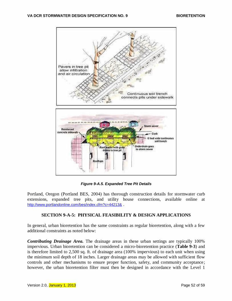
VA DCR STORMWATER DESIGN SPECIFICATION NO. 9 BIORETENTION
Version 2.0, January 1, 2013 Page 52 of 59
Figure 9-A.5. Expanded Tree Pit Details
Portland, Oregon (Portland BES, 2004) has thorough construction details for stormwater curb
extensions, expanded tree pits, and utility house connections, available online at
http://www.portlandonline.com/bes/index.cfm?c=44213& .
SECTION 9-A-5: PHYSICAL FEASIBILITY & DESIGN APPLICATIONS
In general, urban bioretention has the same constraints as regular bioretention, along with a few
additional constraints as noted below:
Contributing Drainage Area. The drainage areas in these urban settings are typically 100%
impervious. Urban bioretention can be considered a micro-bioretention practice (Table 9-3) and
is therefore limited to 2,500 sq. ft. of drainage area (100% impervious) to each unit when using
the minimum soil depth of 18 inches. Larger drainage areas may be allowed with sufficient flow
controls and other mechanisms to ensure proper function, safety, and community acceptance;
however, the urban bioretention filter must then be designed in accordance with the Level 1

VA DCR STORMWATER DESIGN SPECIFICATION NO. 9 BIORETENTION
Version 2.0, January 1, 2013 Page 53 of 59
bioretention filter criteria (Table 9-4). While multiple units can be installed adjacent to large
buildings, parking decks, etc., to maximize the treatment area in ultra-urban watersheds, urban
bioretention is not intended to be used as treatment for large impervious areas (such as parking
lots) as noted in Section 9-A-1.
Adequate Drainage. Urban bioretention practice elevations must allow the untreated stormwater
runoff to be discharged at the surface of the filter bed and ultimately connect to the local storm
drain system.
Available Hydraulic Head. In general, 3 to 5 feet of elevation difference is needed between the
downstream storm drain invert and the inflow point of the urban bioretention practice. This is
generally not a constraint, due to the standard depth of most storm drains systems.
Setbacks from Buildings or Roads. If an impermeable liner and an underdrain are used, no
setback is needed from the building. Otherwise, the standard 10 foot down-gradient setback
applies.
Proximity to Underground Utilities. Urban bioretention practices frequently compete for space
with a variety of utilities. Since they are often located parallel to the road right-of-way, care
should be taken to provide utility-specific horizontal and vertical setbacks. However, conflicts
with water and sewer laterals (e.g., house connections) may be unavoidable, and the construction
sequence must be altered, as necessary, to avoid impacts to existing service.
Overhead Wires. Designers should also check whether future tree canopy heights achieved in
conjunction with urban bioretention practices will interfere with existing overhead telephone,
cable communications and power lines.
Minimizing External Impacts. Because urban bioretention practices are installed in highly urban
settings, individual units may be subject to higher public visibility, greater trash loads, pedestrian
use traffic, vandalism, and even vehicular loads. Designers should design these practices in ways
that prevent, or at least minimize, such impacts. In addition, designers should clearly recognize
the need to perform frequent landscaping maintenance to remove trash, check for clogging, and
maintain vigorous vegetation. The urban landscape context may feature naturalized landscaping
or a more formal deign. When urban bioretention is used in sidewalk areas of high foot traffic,
designers should not impede pedestrian movement or create a safety hazard. Designers may also
install low fences, grates or other measures to prevent damage from pedestrian short-cutting
across the practices.
SECTION 9-A-6: DESIGN CRITERIA
Urban bioretention practices are similar in function to regular bioretention practices except they
are adapted to fit into “containers” within urban landscapes. Therefore, special sizing
accommodations are made to allow these practices to fit in very constrained areas where other
surface practices may not be feasible.

VA DCR STORMWATER DESIGN SPECIFICATION NO. 9 BIORETENTION
Version 2.0, January 1, 2013 Page 54 of 59
6.1. Sizing of Urban Bioretention
The requirements for sizing an urban bioretention filter are the same as that of bioretention and
micro-bioretention described in Section 6 of the conventional Bioretention design specification.
6.2 General Design Criteria for Urban Bioretention
Design of urban bioretention should follow the general guidance presented in the main part of
this Bioretention design specification. The actual geometric design of urban bioretention is
usually dictated by other landscape elements such as buildings, sidewalk widths, utility corridors,
retaining walls, etc. Designers can divert fractions of the runoff volume from small impervious
surfaces into micro-bioretention units that are integrated with the overall landscape design. Inlets
and outlets should be located as far apart as possible. The following is additional design guidance
that applies to all variations of urban bioretention:
Each individual urban bioretention unit should be stenciled or otherwise permanently marked
to designate it as a stormwater management facility. The stencil or plaque should indicate (1)
its water quality purpose, (2) that it may pond briefly after a storm, and (3) that it is not to be
disturbed except for required maintenance.
The ground surface of the micro-bioretention cell should slope 1% towards the outlet, unless
a stormwater planter is used.
The soil media depth should be a minimum of 18 inches.
If large trees and shrubs are to be installed, soil media depths should be a minimum of 4 feet .
All urban bioretention practices should be designed to fully drain within 24 hours.
Any grates used above urban bioretention areas must be removable to allow maintenance
access.
The inlet(s) to urban bioretention should be stabilized using VDOT #3 stone, splash block,
river stone or other acceptable energy dissipation measures. The following forms of inlet
stabilization are recommended:
o Downspouts to stone energy dissipaters.
o Sheet flow over a depressed curb with a 3-inch drop.
o Curb cuts allowing runoff into the bioretention area.
o Covered drains that convey flows across sidewalks from the curb or downspouts.
o Grates or trench drains that capture runoff from the sidewalk or plaza area.
Pre-treatment options overlap with those of regular bioretention practices. However, the
materials used may be chosen based on their aesthetic qualities in addition to their functional
properties. For example, river rock may be used in lieu of rip rap. Other pretreatment options
may include one of the following:
o A trash rack between the pre-treatment cell and the main filter bed. This will allow trash
to be collected from one location.
o A trash rack across curb cuts. While this trash rack may clog occasionally, it keeps trash
in the gutter, where it can be picked up by street sweeping equipment.
o A pre-treatment area above ground or a manhole or grate directly over the pre-treatment
area.
Overflows can either be diverted from entering the bioretention cell or dealt with via an
overflow inlet. Optional methods include the following:

VA DCR STORMWATER DESIGN SPECIFICATION NO. 9 BIORETENTION
Version 2.0, January 1, 2013 Page 55 of 59
o Size curb openings to capture only the Tv and bypass higher flows through the existing
gutter.
o Use landscaping type inlets or standpipes with trash guards as overflow devices.
o Use a pre-treatment chamber with a weir design that limits flow to the filter bed area.
6.3 Specific Design Issues for Stormwater Planters
Since stormwater planters are often located near building foundations, waterproofing by using a
watertight concrete shell or an impermeable liner is required to prevent seepage.
6.4 Specific Design Issues for Expanded Tree Pits
The bottom of the soil layer must be a minimum of 4 inches below the root ball of plants to
be installed.
Extended tree pits designs sometimes cover portions of the filter media with pervious pavers
or cantilevered sidewalks. In these situations, it is important that the filter media is connected
beneath the surface so that stormwater and tree roots can share this space.
Installing a tree pit grate over filter bed media is one possible solution to prevent pedestrian
traffic and trash accumulation.
Low, wrought iron fences can help restrict pedestrian traffic across the tree pit bed and serve
as a protective barrier if there is a drop-off from the pavement to the micro-bioretention cell.
A removable grate capable of supporting typical H-20 axel loads may be used to allow the
tree to grow through it.
Each tree needs a minimum of 400 cubic feet of shared root space.
6.5 Specific Design Issues for Stormwater Curb Extensions
Roadway stability can be a design issue where stormwater curb extensions are installed. Consult
design standards pertaining to roadway drainage. It may be necessary to provide a barrier to keep
water from saturating the road’s sub-base and demonstrate it is capable of supporting H-20 axel
loads.
6.6 Planting and Landscaping Considerations
Plant selection for urban bioretention areas should take into account the extreme conditions of
the urban landscape: reduced sunlight due to building shade, heat island effects, safety concerns
related to volume of pedestrian traffic and visibility, etc. Also, the degree of landscape
maintenance that can be provided will determine some of the planting choices for urban
bioretention areas. The planting cells can be formal gardens or naturalized landscapes.
In areas where less maintenance will be provided and where trash accumulation in shrubbery or
herbaceous plants is a concern, consider a “turf and trees” landscaping model. Spaces for
herbaceous flowering plants can be included. This may be attractive at a community entrance
location.

VA DCR STORMWATER DESIGN SPECIFICATION NO. 9 BIORETENTION
Version 2.0, January 1, 2013 Page 56 of 59
Native trees or shrubs are preferred for urban bioretention areas, although some ornamental
species may be used. As with regular bioretention, the selected perennials, shrubs, and trees must
be tolerant of salt, drought, and inundation. Additionally, tree species should be those that are
known to survive well in the compacted soils and polluted air and water of an urban landscape.
SECTION 9-A-7: URBAN BIORETENTION MATERIAL SPECIFICATIONS
Please consult the main part of this design specification (Table 9.7) for the typical materials
needed for filter media, stone, mulch and other bioretention features. The unique components for
urban bioretention may include the inlet control device, a concrete box or other containing shell,
protective grates, and an underdrain that daylights to another stormwater practice or connects to
the storm drain system. The underdrain should:
Consist of slotted pipe greater than or equal to 4 inches in diameter, placed in a layer of
washed (less than 1% passing a #200 sieve) VDOT #57 stone.
Have a minimum of 2 inches of gravel laid above and below the pipe.
Be laid at a minimum slope of 0.5 %.
Extend the length of the box filter from one wall to within 6 inches of the opposite wall, and
may be either centered in the box or offset to one side.
Be separated from the soil media by an appropriate filter fabric for the particular application,
based on AASHTO M288-06, or a 2 to 3 inch layer of either washed VDOT #8 stone or 1/8-
to 3/8-inch pea gravel.
SECTION 9-A.8: CONSTRUCTION
The construction sequence and inspection requirements for urban bioretention are generally the
same as micro-bioretention practices. Consult the construction sequence and inspection guidance
provided in the main part of this design specification. In cases where urban bioretention is
constructed in the road or right-of-way, the construction sequence may need to be adjusted to
account for traffic control, pedestrian access and utility notification.
Urban bioretention areas should only be constructed after the drainage area to the facility is
completely stabilized. The specified growth media should be placed and spread by hand with
minimal compaction, in order to avoid compaction and maintain the porosity of the media. The
media should be placed in 8 to 12 inch lifts with no machinery allowed directly on the media
during or after construction. The media should be overfilled above the proposed surface
elevation, as needed, to allow for natural settling. Lifts may be lightly watered to encourage
settling. After the final lift is placed, the media should be raked (to level it), saturated, and
allowed to settle for at least one week prior to installation of plant materials.
SECTION 9-A-9: MAINTENANCE
Routine operation and maintenance are essential to gain public acceptance of highly visible
urban bioretention areas. Weeding, pruning, and trash removal should be done as needed to
VA DCR STORMWATER DESIGN SPECIFICATION NO. 9 BIORETENTION
Version 2.0, January 1, 2013 Page 57 of 59
maintain the aesthetics necessary for community acceptance. During drought conditions, it may
be necessary to water the plants, as would be necessary for any landscaped area.
To ensure proper performance, inspectors should check that stormwater infiltrates properly into
the soil within 24 hours after a storm. If excessive surface ponding is observed, corrective
measures include inspection for soil compaction and underdrain clogging. Consult the
maintenance guidance outlined in the main part of this design specification.
SECTION 9-A-10: DESIGN REFERENCES
Center for Watershed Protection. 2006. Urban Watershed Forestry Manual. Part 2: Conserving
and Planting Trees at Development Sites. Ellicott City, MD. Available online at: http://www.cwp.org/forestry/index.htm
City of Portland. Bureau of Environmental Services. (Portland BES). 2004. Portland Stormwater
Management Manual. Portland, OR. http://www.portlandonline.com/bes/index.cfm?c=dfbcc
Credit Valley Conservation. 2008. Credit River Stormwater Management Manual. Mississauga,
Ontario.
Northern Virginia Regional Commission. 2007. Low Impact Development Supplement to the
Northern Virginia BMP Handbook. Fairfax, Virginia
Saxton, K.E., W.J. Rawls, J.S. Romberger, and R.I. Papendick. 1986. “Estimating generalized
soil-water characteristics from texture.” Soil Sci. Soc. Am. J. 50(4):1031-1036.
Schueler, T., D. Hirschman, M. Novotney and J. Zielinski. 2007. Urban stormwater retrofit
practices. Manual 3 in the Urban Subwatershed Restoration Manual Series. Center for
Watershed Protection, Ellicott City, MD.
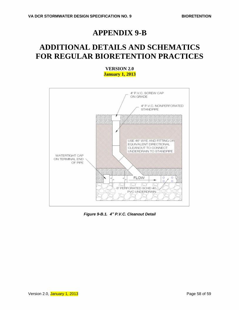
VA DCR STORMWATER DESIGN SPECIFICATION NO. 9 BIORETENTION
Version 2.0, January 1, 2013 Page 58 of 59
APPENDIX 9-B
ADDITIONAL DETAILS AND SCHEMATICS
FOR REGULAR BIORETENTION PRACTICES
VERSION 2.0
January 1, 2013
Figure 9-B.1. 4” P.V.C. Cleanout Detail

VA DCR STORMWATER DESIGN SPECIFICATION NO. 9 BIORETENTION
Version 2.0, January 1, 2013 Page 59 of 59
Figure 9-B.2. Typical Bioretention Basin Berm