1 procedures and interrupts chapter 5 n stack n procedure n software interrupt u bios-level access u...
Post on 19-Dec-2015
221 views
TRANSCRIPT

1
Procedures and InterruptsProcedures and Interrupts
Chapter 5Chapter 5 StackStack ProcedureProcedure Software InterruptSoftware Interrupt
BIOS-level accessDOS-level access
Video DisplayVideo Display Direct Video access

2
The StackThe Stack The stack resides in the stack segment (in
main memory) who’s segment number is in the SS register
The SP register holds the offset address of the last element added to the stack
If the stack was allocated with the directive .STACK 100h : Then SP should, initially, contain 100h
(pointing to the top of the empty stack)

3
PUSH (16-bit case)PUSH (16-bit case) PUSH source
will decrement SP by 2 and copy the content of
source into word at SS:SP little endian: low order byte
at lowest offset Ex: (see figure)
mov ax,06 push ax mov ax,0A5h push ax
This is for a source of type word (reg16 or mem16).
imm16 are allowed only on 286 and later processors)

4
PUSH (32-bit case)PUSH (32-bit case) With a 32-bit operand (.386 directive):
push source Decrements SP by 4 and copies the content of
source into the double word at address SS:SP Little endian convention. Ex:
mov eax,12345678h push eax
will decrease SP by 4 and will move: 78h at SS:SP 56h at SS:SP+1 34h at SS:SP+2 12h at SS:SP+4

5
POPPOP
The POP instruction undoes the action of PUSH POP destination
For a 16-bit destination operand: the word at SS:SP is copied into destination SP is incremented by 2
For a 32-bit destination operand: the dword at SS:SP is copied into destination SP is incremented by 4
The destination operand cannot be imm
6
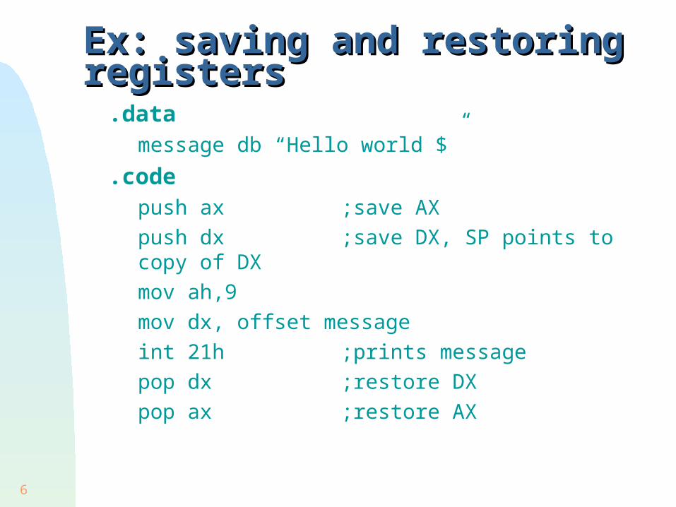
Ex: saving and restoring registersEx: saving and restoring registers .data
message db “Hello world $” .code
push ax ;save AX push dx ;save DX, SP points to copy of
DX mov ah,9 mov dx, offset message int 21h ;prints message pop dx ;restore DX pop ax ;restore AX

7
More Saving and RestoringMore Saving and Restoring
PUSHA (.286) pushes AX, CX, DX, BX, SP, BP, SI, DI on stack and POPA pops the same registers in reverse order
PUSHAD (.386) pushes EAX, ECX, EDX, EBX, ESP, EBP, ESI, EDI on stack and POPAD pops the same registers in reverse order
PUSHF and POPF pushes and pops the FLAGS register onto and from the stack
PUSHFD and POPFD (.386) pushes and pops the EFLAGS register onto and from the stack

8
ProceduresProcedures Procedures are defined like this:
name PROC [type] ... set of instructions... RET name ENDP
The “type” is either NEAR or FAR To transfer control to the procedure “name” we do:
CALL [type PTR] name RET transfers control to the instr. following CALL The default for “type” and “type PTR” is:
NEAR: for memory models: tiny, small, compact FAR: for memory models: medium, large, huge

9
CALL & RET (NEAR Procedures)CALL & RET (NEAR Procedures) Upon a CALL to a NEAR procedure:
SP is decremented by 2 The content of IP is copied at SS:SP
this is the offset address of the instruction following CALL (where the procedure must return)
The offset address of the first instruction in the called procedure is copied into IP
this will thus be the next instruction to execute Upon a RET from a NEAR procedure:
the word at SS:SP is popped into IP (so that SP is automatically incremented by 2)
(the instruction pointed by IP is then executed)

10
CALL & RET (NEAR Procedures)CALL & RET (NEAR Procedures)
0006IP 0080IP 0009IP

11
CALL & RET (FAR Procedures)CALL & RET (FAR Procedures) Upon a CALL to a FAR procedure:
CS and then IP are pushed onto the stack this is the segment:offset address of the instruction
following CALL (where the procedure must return) The segment:offset address of the first instruction in
the called procedure is copied into CS:IP this will thus be the next instruction to execute
A RET from a FAR procedure effectively does: POP IP POP CS
Hence: the instruction at CS:IP is then executed

12
CALL & RET (FAR Procedures)CALL & RET (FAR Procedures)
0006IP 0080IP 0009IP2FC0CS 2FC0CS2FC0CS

13
When does a procedure needs to be FAR?When does a procedure needs to be FAR?
A NEAR CALL is faster than a FAR CALL Procedures located in the same segment
as the code that CALLs them can be of type NEAR since the code segment number (in CS) is the
same for both the procedure and the caller Procedures located in a different segment
than the code that CALLs them must be of type FAR since the procedure and the caller have a
different code segment number

14
Using Procedures in irvine.libUsing Procedures in irvine.lib
Separately assembled procedures under the .model small will be combined, by the linker, into the same code segment this is the case for the procedures in irvine.lib so use a NEAR call to call these procedures you should also use .model small for your code
that call procedures in irvine.lib other memory models will be used when linking
with high level language (HLL) procedures (chap 9 and 13)

15
Passing Arguments to ProceduresPassing Arguments to Procedures
Arguments can be passed to procedures via the stack: this is the technique used in HLLs.
We will use this only later (chap 9) global variables: the scope of a variable is
the .ASM file into which it is defined must use PUBLIC and EXTRN directive to make
them visible to other .ASM files contrary to modular programming practice
registers: fastest way to pass arguments
16
Using ProceduresUsing Procedures
When a procedure returns to the caller it should preserve the content of the registers (except those used to return a value) should save first the content of the registers that
it will modify and restore them just before returning to the caller
Caution on stack usage: SP points to the return address when entering
the procedure. Make sure that this is the case just before executing RET !!
ProcEx.html

17
InterruptsInterrupts The term interrupt is used in many different ways A hardware interrupt is a signal generated by any
part of the hardware that needs immediate attention of the processor
A software interrupt (sometimes called a Trap) is a call to an Interrupt Service Routine (ISR) of the Operating System (here: either DOS or BIOS) produced by the instruction INT n in a program
A processor exception is an automatically generated trap in response to an exceptional condition (abnormal program execution). Ex: divide overflow, coprocessor not available...

18
Hardware InterruptsHardware Interrupts
When a hardware component (ex: a peripheral device) needs CPU attention, the controller associated with this component sends a Interrupt Request (INTR) signal to the CPU and puts an Interrupt Number (0 to FFh) onto the data bus
The CPU uses this interrupt number to index the interrupt vector table (IVT) located at physical addresses 00000h to 003FFh (pp.33)
Each entry of this table, called an interrupt vector, contains the segment:offset address of the Interrupt Handler (ISR) servicing that interrupt.
To service an interrupt, the CPU transfers control to the corresponding ISR

19
The Interrupt Vector Table (IVT)The Interrupt Vector Table (IVT) Each entry of the IVT
occupies 4 bytes At entry 0 of the IVT
we have the offset address and then the segment address of the ISR handling INT 0
At entry n of the IVT we have the offset address and then the segment address of the ISR handling INT n

20
Interrupt ProcessingInterrupt Processing
The same mechanisms are used to handle all types of interrupts (hardware, software, exception)
When an interrupt occurs: The CPU pushes the FLAGS register onto the stack The CPU pushes onto the stack the far (segment:offset)
return address (ie: that of the next instruction) From the interrupt number N, the CPU fetches the Nth
entry of the IVT and transfers control to that ISR The ISR execute a IRET instruction to return control to
the program at the point of interruption (this pops off the stack the far return address and the FLAGS register)

21
Ex: using INT 10h BIOS video servicesEx: using INT 10h BIOS video services

22
Interrupt Service RoutinesInterrupt Service Routines A ISR is like a procedure except that:
a transfer to a ISR pushes FLAGS in addition to a far return address
a ISR returns with IRET instead of RET But since the point of interruption can occur
anywhere in a program, it is crucial for a ISR to not modify the content of any register
How to write a ISR and how to initialize the corresponding entry in the IVT? (chap 15)
For now let us examine what are the ISRs that are provided by DOS and BIOS (and how to use them) to perform I/O operations
23
Common Software InterruptsCommon Software Interrupts
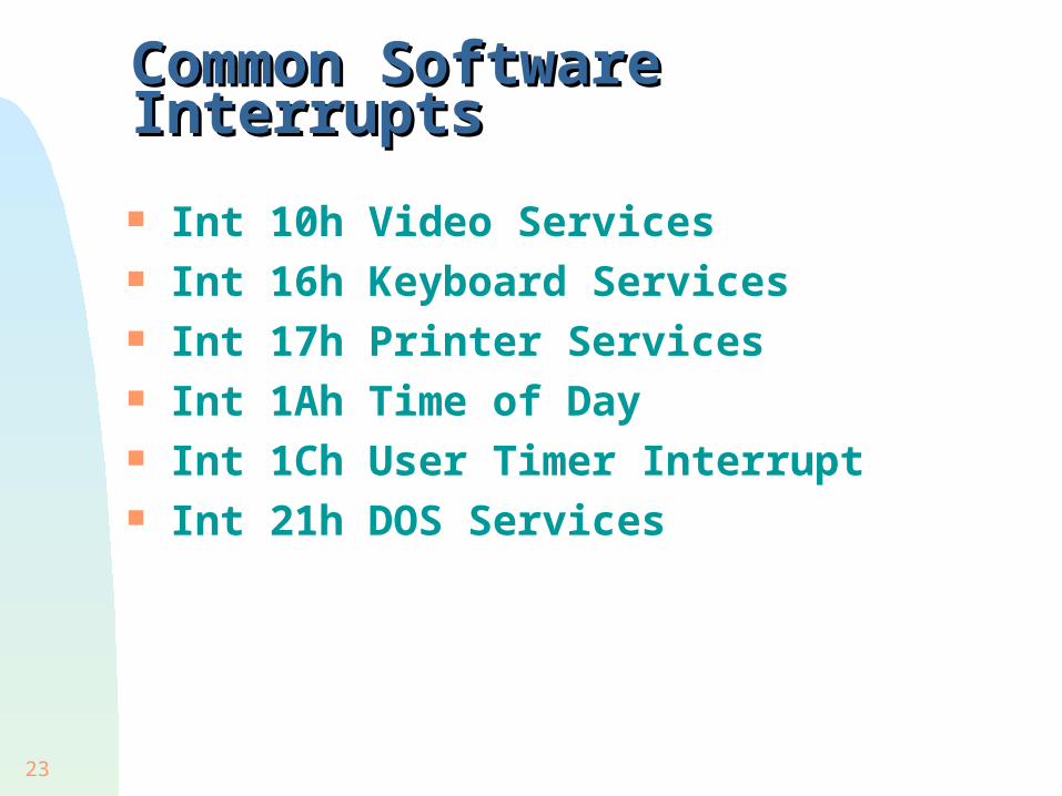
Int 10h Video Services Int 16h Keyboard Services Int 17h Printer Services Int 1Ah Time of Day Int 1Ch User Timer Interrupt Int 21h DOS Services

24
MS-DOS Function Calls MS-DOS Function Calls
A MS-DOS function is called upon the execution of INT 21h The actual function to be performed depends on
the function number stored in AH about 90 different functions are supported
We have already seen functions 01h, 02h, 09h and 4Ch
We now briefly view some other functions see more details in section 5.5 of your textbook

25
Output FunctionsOutput Functions
02h: Character Output 05h: Printer Output 06h: Direct Output 09h: String Output

26
Input FunctionsInput Functions
01h: Filtered Input With Echo 06h: Direct Input Without Waiting 07h: Direct Input, No Ctrl-Break 08h: Direct Input with Ctrl-Break 0Ah: Buffered Input 0Bh: Get Input Status 0Ch: Clear Input Buffer, Invoke Input Function 3Fh: Read From File or Device

27
Single Character input (DOS)Single Character input (DOS)
For all these functions, the next character in the keyboard buffer is stored in AL
Wait for keystroke: function 6 (with DL=FFh) always returns even when the buffer is empty
Function 1 and 8 will return control to DOS when Ctrl-Break is entered

28
Ex: AH=06h clear_keyboardEx: AH=06h clear_keyboard
Clear_keyboard procpush axpush dx
L1:mov ah, 6mov dl, 0FFhint 21hjnz L1pop dxpop axret
clear_keyboard endp

29
Buffered Input (DOS)Buffered Input (DOS) Function 0Ah reads (from stdin) a string of up to
255 characters and stores it in a buffer User input is terminated with 0Dh (CR) Non ASCII keys (ex: PgUp, arrows, Fn...) are
filtered out and Ctrl-Break is active DX contains the offset of the Buffer
1st char = max number of char allowed (including 0Dh) 2nd char = number of chars actually entered (excluding 0Dh)

30
Ex: Using buffered input function 0AhEx: Using buffered input function 0Ah
.data keyboardArea label byte maxkeys db 32 ;max # chars allowed charsInput db ? ;# of chars actually entered buffer db 32 dup('0') ;holds input string .code mov ah,0Ah mov dx,offset keyboardArea int 21h
the CR (0Dh) is the last char entered in the buffer

31
Date/Time FunctionsDate/Time Functions
2Ah: Get Date 2Bh: Set Date 2Ch: Get Time 2Dh: Set Time
cx: yeardh: monthdl: day
ch: hourcl: minutedh: second

32
Keyboard KeysKeyboard Keys ASCII keys:
those that have an ASCII code: letters, digits, punctuation’s, arithmitic’s, Esc, CR, Bksp, Tab
Shift Keys: normally used in combination with another key:
left and right shifts, Caps Lock, Ctrl, Alt, Num Lock, Scroll Lock
Function Keys: used in programs to perform special functions:
F1-F12, arrows, Home, PgUp, PgDn, End, Ins, Del

33
Scan CodesScan Codes Only ASCII keys have an ASCII code but all keys
have a SCAN CODE (1byte). See scancodes.html When we strike a key:
The keyboard interrupts (INT 9h) the CPU and sends the Scan Code to I/O port 60h
The BIOS INT 9h reads this I/O port and uses the scan code to index a table to get the ASCII code. Both codes are sent to the keyboard buffer only if it is not a shift key (used alone)
For each word in the keyboard buffer: low byte = ASCII code of the key, or 0 if it is not an
ASCII key high byte = Scan Code of key

34
BIOS input function INT 16hBIOS input function INT 16h When AH=10h, INT 16h will load AX with
the next word in the keyboard buffer: mov ah,10h int 16h ;AH = Scan Code, AL = ASCII code
The input character will not be echoed on screen
Useful for reading (and identify) the function key pressed by the user they can be identified only with their scan code
Keyboard input cannot be redirected on the DOS command line (unlike INT 21h)

35
Video AdaptersVideo Adapters
Screen display is controlled by a video adapter which consists of: A memory (video buffer) which contains all the
information displayed on screen A video controller that displays on screen the
content of the video buffer Typical resolutions (in pixels X pixels):
640 X 480 (standard VGA) 800 X 600 (super VGA) 1024 X 768 (extended VGA) ....(higher resolutions)....
36
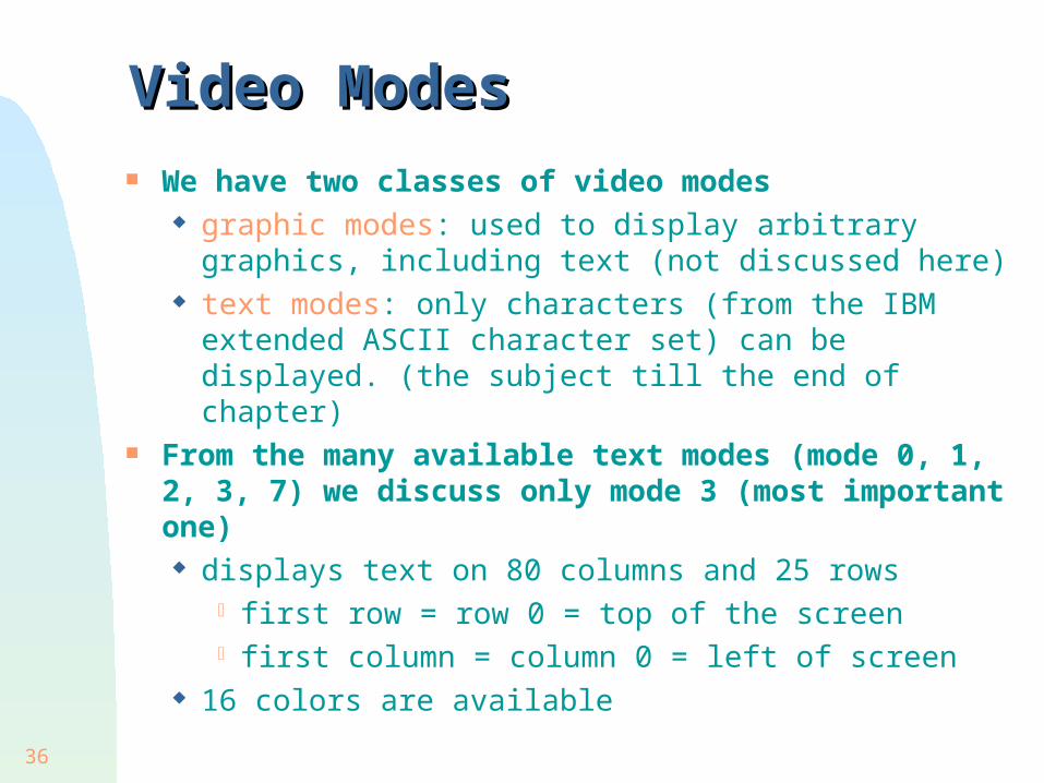
Video ModesVideo Modes We have two classes of video modes
graphic modes: used to display arbitrary graphics, including text (not discussed here)
text modes: only characters (from the IBM extended ASCII character set) can be displayed. (the subject till the end of chapter)
From the many available text modes (mode 0, 1, 2, 3, 7) we discuss only mode 3 (most important one) displays text on 80 columns and 25 rows
first row = row 0 = top of the screen first column = column 0 = left of screen
16 colors are available

37
Video PagesVideo Pages Each character displayed is represented by
1 word low order byte = ASCII code (IBM extended) high order byte = Attribute Byte (specify how the
character will be displayed) Each of these words is stored in the video
buffer starting at physical address B80000h One screen of text (80 X 25 X 2 = 4000 bytes)
requires 1 video page of 4KB VGA (and better) adapters can hold 8 video
pages: page 0 to 7

38
Video Pages (cont.)Video Pages (cont.)
only the active page is displayed: the first word of the page displays the character
at the upper left corner: (row,column) = (0,0) the second word displays the character at (row,
column) = (1,0) the 3rd word displays the char at (2,0)... ...the last word displays the char at (24,79)
(other pages can be modified while the active page is being displayed)

39
The Attribute ByteThe Attribute Byte
The foreground bits determine the color of the character
The background bits determine the color of the background
The msb of foreground is an intensity bit The blinking bit applies only to foreground
40
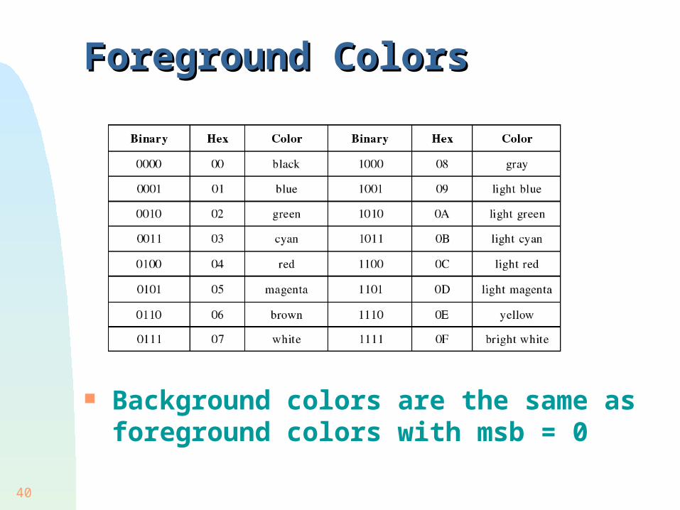
Foreground ColorsForeground Colors
Background colors are the same as foreground colors with msb = 0
41
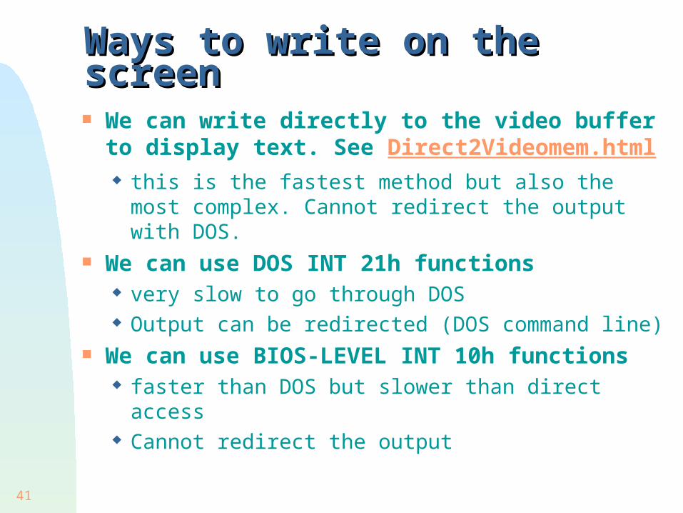
Ways to write on the screenWays to write on the screen
We can write directly to the video buffer to display text. See Direct2Videomem.html this is the fastest method but also the most
complex. Cannot redirect the output with DOS. We can use DOS INT 21h functions
very slow to go through DOS Output can be redirected (DOS command line)
We can use BIOS-LEVEL INT 10h functions faster than DOS but slower than direct access Cannot redirect the output

42
Some BIOS INT 10h functionsSome BIOS INT 10h functions
Function 00h: set video mode. AL contains the desired text mode. Ex: mov ah,0 ;set video mode mov al,3 ;choose text mode 3 int 10h ;mode is set
Function 05h: set active display page. AL contains the desired page number. Ex: mov ah,5 ;set display page mov al,1 ;page # to display int 10h ;display chosen page
Page 0 is the usual page displayed by DOS Each page has its own cursor.

43
Some BIOS INT 10h functions (cont.)Some BIOS INT 10h functions (cont.) Function 02h: Set cursor position.
Input: BH = chosen page number DH = chosen row, DL = chosen column
mov ah,2 ;set cursor position mov dh,10 ;row 10 mov dl,18 ;column 18 int 10h ;cursor is set
Function 03h: Get cursor position. Input: BH = chosen page number Output: DH = row, DL = column
mov ah,3 ;get cursor position int 10h ;DH=row, DL=column

44
Other BIOS INT 10h functionsOther BIOS INT 10h functions
See chap 5 of textbook for details 08h: Read Character and Attribute at
cursor position 09h: Set Character and Attribute at cursor
position 06h: Scroll window up (by n rows) 07h: Scroll window down (by n rows) ...and many more!!

45
Trace Program RecursionTrace Program Recursion
main proc
0000 mov ax, 8
0003 push ax
0004 call Factorial
0007 mov ax, 4C00h
000A int 21h
main endp
Factorial proc000C push bp000D mov bp, sp000F mov ax, [bp+4]0012 cmp ax, 10015 ja L10017 mov ax, 1001A jmp L2001D L1: dec ax001E push ax001F call Factorial0022 mov bx, [bp+4]0025 mul bx0027 L2: pop bp0028 ret 2
Factorial endp