1 nova mems, 2 cnes, 3 memscap
TRANSCRIPT

Copyright 2008 ‐ Reproduction is not allowed without authorization
Reliability assessment of RF MEMS switches
C. Seguineau1, A. Broué1, J. Dhennin1, T. Fourcade1,
J.M. Desmarres2, F. Courtade2,
M. Colin3
1‐
NOVA MEMS, 2‐
CNES, 3‐
MEMSCAP
7th ESA Round Table on MNT for Space Apps

Copyright 2008 ‐ Reproduction is not allowed without authorization 2
Reliability of a switch RF
Outline
•
Introduction
•
Approaches for Reliability assessment
•
Accelerated aging
•
Physics of Failure
•
Conclusion

Copyright 2008 ‐ Reproduction is not allowed without authorization 3
Reliability of a switch RF
Outline
•
Introduction
•
Approaches for Reliability assessment
•
Accelerated aging
•
Physics of Failure
•
Conclusion

Copyright 2008 ‐ Reproduction is not allowed without authorization 4
Reliability of a switch RF
The POLYNOE EDA Project
•
Aim: Prove the Physics of Failure concept for reliability assessment of MEMS switches

Copyright 2008 ‐ Reproduction is not allowed without authorization 5
Reliability of a switch RF
Introduction
•
Several technologies for switching operationMESFET PIN Diode MEMS
Series Resistance (Ω) 3 to 5 1 < 1
Loss @1GHz (dB) 0.5 to 1.0 0.5 to 1.0 0.1
Isolation @1GHz (dB) 20 to 40 40 > 40
IP3 (dBm) 40 to 60 30 to 45 > 66
1 dB compression (dBm) 20 to 35 25 to 30 >33
Size (mm²) 1 to 5 0.1 <0.1
Switching speed ~ ns ~ µs ~ µs
Control Voltage (V) 8 3 to 5 3 to 30
Control Current < 10 µA 10 mA < 10 µA
MESFET PIN Diode MEMS
Series Resistance (Ω) 3 to 5 1 < 1
Loss @1GHz (dB) 0.5 to 1.0 0.5 to 1.0 0.1
Isolation @1GHz (dB) 20 to 40 40 > 40
IP3 (dBm) 40 to 60 30 to 45 > 66
1 dB compression (dBm) 20 to 35 25 to 30 >33
Size (mm²) 1 to 5 0.1 <0.1
Switching speed ~ ns ~ µs ~ µs
Control Voltage (V) 8 3 to 5 3 to 30
Control Current < 10 µA 10 mA < 10 µA
XLIM Lab:
Nanogap switches
(a few tens of nanoseconds !)

Copyright 2008 ‐ Reproduction is not allowed without authorization 6
Reliability of a switch RF
Introduction
•
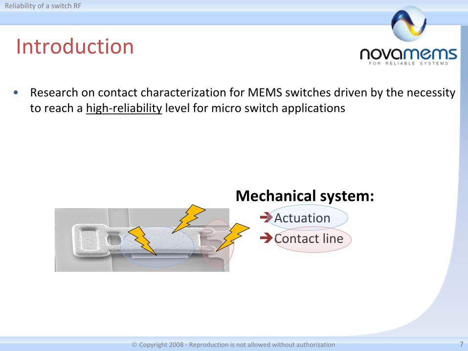
Research on contact characterization for MEMS switches driven by
the necessity
to reach a high‐reliability
level for micro switch applications
Copyright 2008 ‐ Reproduction is not allowed without authorization 7
Reliability of a switch RF
Introduction
Mechanical system:Actuation
Contact line
•
Research on contact characterization for MEMS switches driven by
the necessity
to reach a high‐reliability
level for micro switch applications

Copyright 2008 ‐ Reproduction is not allowed without authorization 8
Reliability of a switch RF
Introduction
•
FMEA: identification of the main failure mechanisms» Field induced dielectric charging
» Temperature induced deformation of the structures
» Degradation of the electrical micro‐contact
04/29/2010
+20°C +180°C

Copyright 2008 ‐ Reproduction is not allowed without authorization 9
Reliability of a switch RF
Outline
•
Introduction
•
Approaches for Reliability assessment
•
Accelerated aging
•
Physics of Failure
•
Conclusion

Copyright 2008 ‐ Reproduction is not allowed without authorization 10
Reliability of a switch RF
Reliability assessment
•
Several approaches
COTSCOTS
Black box approachBlack box approachTechnological
Analysis
Technological
Analysis
LifetestLifetest LifetestLifetest
Reliability assessmentReliability assessment
Physics of FailureVirtual prototypingPhysics of FailureVirtual prototyping
Adapted
Qualification
Adapted
Qualification
1 2 3
Simulation LifetestSimulation Lifetest
Copyright 2008 ‐ Reproduction is not allowed without authorization 11
Reliability of a switch RF
Reliability assessment
•
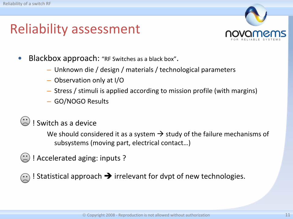
Blackbox
approach: “RF Switches as a black box”.
– Unknown die / design / materials / technological parameters
– Observation only at I/O – Stress / stimuli is applied according to mission profile (with margins)
– GO/NOGO Results
! Switch as a deviceWe should considered it as a system study of the failure mechanisms of
subsystems (moving part, electrical contact…)
! Accelerated aging: inputs ?
! Statistical approach irrelevant for dvpt
of new technologies.
Copyright 2008 ‐ Reproduction is not allowed without authorization 12
Reliability of a switch RF
Reliability assessment
•
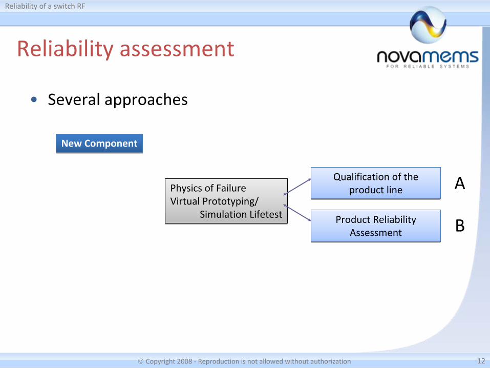
Several approaches
New ComponentNew Component
Qualification of the
product line
Qualification of the
product line
Product Reliability
Assessment
Product Reliability
Assessment
Physics of FailureVirtual Prototyping/
Simulation Lifetest
Physics of FailureVirtual Prototyping/
Simulation LifetestB
A

Copyright 2008 ‐ Reproduction is not allowed without authorization 13
Reliability of a switch RF
Reliability assessment
•
New technologies: Production line ? Materials & Design
The mechanical
properties differ from MacroWorld:
– Strong interaction between microstructural features and the
geometry of the thin coatings (eg. Thicknesses)
– Microstructural properties greatly influenced by the process (kind
of deposition, temperatures, sacrificial layers…)
Process flowProcess flow Mechanical
properties
Mechanical
properties
MicrostructureMicrostructure
IMPACT
Δ
parameters ?Δ
parameters ?Physical prop.Physical prop.
Elec. prop.Elec. prop. Performances Performances
Failure ?Failure ?
Copyright 2008 ‐ Reproduction is not allowed without authorization 14
Reliability of a switch RF
Reliability assessment
•
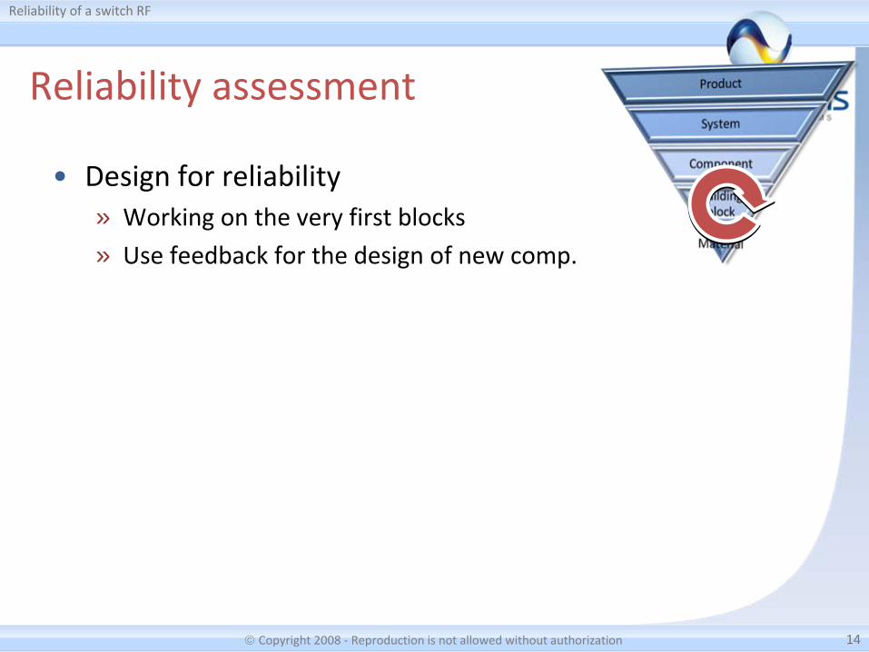
Design for reliability» Working on the very first blocks
» Use feedback for the design of new comp.

Copyright 2008 ‐ Reproduction is not allowed without authorization 15
Reliability of a switch RF
Plastic DeformationMaterial transferStrain hardening
Reliability assessment
Reproducible
contact area
Electrical
degradation‐Electron mobility-Alloys-Impurities
Material
resistivity
High E, H
low
deformation and
high contact
stability
High melting
point
to avoid
electro migration
?
Physical
properties
Resistance to
Oxidation,
contaminations…PerformancesPerformances ReliabilityReliability
Electrical arcingLocal welding
OxidationAdsorption
Mechanical
degradation
Chemical
degradation
•
Design for reliability: necessity of trade‐offs

Copyright 2008 ‐ Reproduction is not allowed without authorization 16
Reliability of a switch RF
Outline
•
Introduction
•
Approaches for Reliability assessment
•
Accelerated aging
•
Physics of Failure
•
Conclusion

Copyright 2008 ‐ Reproduction is not allowed without authorization 17
Reliability of a switch RF
Accelerated aging
•
Creep (1/2)» Model:
– Power law for secondary creep
(n
is the creep exponent)
– Arrhenius acceleration factor
(Q
is the activation energy)
» Experiment– Characterization of thermally
actuated MEMS switches
(MEMSCAP, EDA POLYNOE program)
– Loss of isolation with cycles: gap
between the electrodes
RTQ
dA p
n
exp
Before After 3 weeks @150°C(closed position)

Copyright 2008 ‐ Reproduction is not allowed without authorization 18
Reliability of a switch RF
Accelerated aging
•
Creep (2/2)» Modelling the evolution of the gap with temperature and
storage duration170°C
0
0.2
0.4
0.6
0.8
1
1.2
0 0.2 0.4 0.6 0.8 1 1.2Storage duration (h)
Gap
(A.U.)
Power law fit nAtgap
0
0.02
0.04
0.06
0.08
0.1
0.12
0.14
0.16
0.18
0 50 100 150 200Temperature (°C)
n
n
versus T° 0
2
4
6
8
10
12
14
0 100 200 300 400 500 600
Holding time in the closed position (h)
Gap
(µm) 200°C
170°C
150°C
120°C
100°C
80°C
50°C
Failure Failure
TTF200°C TTF170°C
TTF predictionTTF prediction

Copyright 2008 ‐ Reproduction is not allowed without authorization 19
Reliability of a switch RF
Accelerated aging
•
Cycling» Great influence of the
testing method on the
reliability– Progressive increase
of the contact
resistance for cold
switching
– Erratic behaviour in
hot switching

Copyright 2008 ‐ Reproduction is not allowed without authorization 20
Reliability of a switch RF
Accelerated aging
•
DC Stress / ESD aging for charging effect quantification
Shift of C‐V characteristic with
cycles / DC stress / ESD stress
J. Ruan et al. (LAAS‐CNRS) : FAME (ANR) project
TTF predictionTTF prediction
TTF
Copyright 2008 ‐ Reproduction is not allowed without authorization 21
Reliability of a switch RF
Accelerated aging
•
Radiations» Expected effects: Damage of the dielectric layer
– modification of Vpi
/Vpo
– Increase of leakage current– Single event transient: auto‐actuation

Copyright 2008 ‐ Reproduction is not allowed without authorization 22
Reliability of a switch RF
Outline
•
Introduction
•
Approaches for Reliability assessment
•
Accelerated aging
•
Physics of Failure
•
Conclusion

Copyright 2008 ‐ Reproduction is not allowed without authorization 23
Reliability of a switch RF
Physics of Failure
•
Material level» Evaluate the mechanical properties
through mechanical actuation of
dedicated specimens
» Wide range of materials
– Metals (and alloys)
– Ceramics
– Polymers
» Deposited on substrate or
freestanding thin coatings
Deposited
µtensile apparatusµtensile apparatus NanoindenterNanoindenter
Tensile testTensile test BendingBending nanoindentationnanoindentation
Freestanding thin coating
+ nanopositionning+ nanopositionning

Copyright 2008 ‐ Reproduction is not allowed without authorization 24
Reliability of a switch RF
•
Micro‐
tensile experiments» Home‐made Developments (NOVA MEMS : C. Seguineau), in
collaboration with SIMaP Laboratories (M. Ignat) and INL (C. Malhaire)
Physics of Failure
Copyright 2008 ‐ Reproduction is not allowed without authorization 25
Reliability of a switch RF
Physics of Failure
•
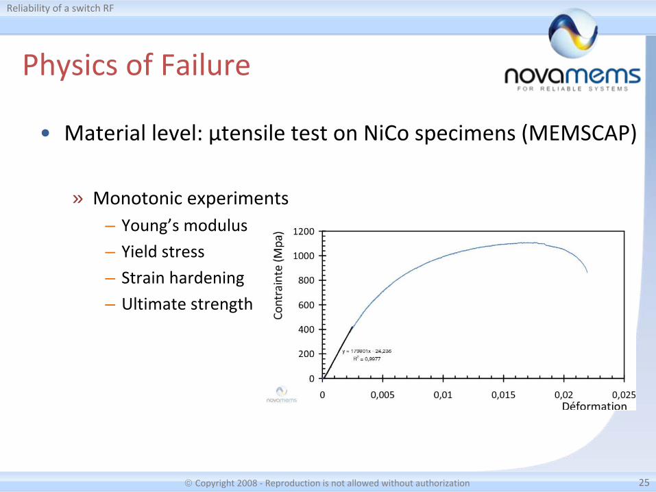
Material level: µtensile test on NiCo specimens (MEMSCAP)
» Monotonic experiments– Young’s modulus
– Yield stress– Strain hardening– Ultimate strength
Copyright 2008 ‐ Reproduction is not allowed without authorization 26
Reliability of a switch RF
Physics of Failure
•
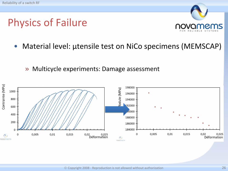
Material level: µtensile test on NiCo specimens (MEMSCAP)
» Multicycle experiments: Damage assessment

Copyright 2008 ‐ Reproduction is not allowed without authorization 27
Reliability of a switch RF
Physics of Failure
•
Electrical contact (subsystem level)» Monitoring Rc
evolution versus:– Intensity I– Load applied F– Compliance level U
– Switching mode (mechanical, cold, hot)
– Number of cycles n
– Hold duration t
(creep)
» High reproductibility of the actuation load (intensity, location on the beam)
Side viewSide view
Top viewTop view
Bump (fixed
contact)
Bridge (mobile contact)
Tip’s location
Contact line
Bridge
I+
I‐V+
V‐

Copyright 2008 ‐ Reproduction is not allowed without authorization 28
Reliability of a switch RF
Physics of Failure
•
Electrical contact (subsystem level)» Select the best
contact material»Investigate power
handling capability
A. Broué
et al., Characterization of Au/Au, Au/Ru and Ru/Ru ohmic
contacts in MEMS Switches improved by a novel methodology.
MOEMS/MEMS 2010, SF, CA.

Copyright 2008 ‐ Reproduction is not allowed without authorization 29
Reliability of a switch RF
Physics of Failure
•
Electrical contact (subsystem level)» Modeling of electrical resistance vs. load applied
– Great influence of contaminant films
Copyright 2008 ‐ Reproduction is not allowed without authorization 30
Reliability of a switch RF
Outline
•
Introduction
•
Approaches for Reliability assessment
•
Accelerated aging
•
Physics of Failure
•
Conclusion

Copyright 2008 ‐ Reproduction is not allowed without authorization 31
Reliability of a switch RF
Conclusion
•
Contact Material:» Performances of the electrical contact strongly linked with the materials used
to perform the contact
» Trade‐off between mechanical and electrical performances to reach the best
reliable operations : “Design for reliability”
» Contact material have to be :– Good electrical conductor for low loss– High melting point to handle power– Appropriate hardness to avoid stiction
phenomenon– Chemical inertness to avoid oxidation
•
Specific experiments and methods developed, but…
Characterization only. Which standards for a qualification ?