1. introduction - nikiet.runikiet.ru/eng/images/stories/nikiet/publications/conf/mntk_nikiet...india...
TRANSCRIPT

1
DESIGN AND DEVELOPMENT OF INDIAN PRESSURIZED WATER REACTOR
R. N. Sen (Advanced Light Water Reactor, BARC, Visakhapatnam, India)
A. K. Balasubramanian, (Engineering, NPCIL, Mumbai, India)
R. S. Yadav (Reactor Projects Group, BARC, Mumbai, India)
1. Introduction
The IPWR is an indigenous project of Department of Atomic Energy (DAE) with joint
participation of Bhabha Atomic Research Centre (BARC) and Nuclear Power Corporation of
India Limited (NPCIL). In this effort it is planned to construct a 900 MWe PWR (IPWR) plant.
It is also planned to source all raw material and equipment from various industries within India.
The plant is being designed as suitable for setting up at seismic zone-IV, which is the
highest seismic excitation in the country for any plant site. Once the design is standardized the
plant can be set up at any location in the country. Identification of an IPWR site for a twin
reactor plant is initiated.
Each of the proposed twin unit reactors is designed for 900 MWe power. Initially, first
IPWR will be operated at 700 MWe using available technology of secondary side of 700 MWe
PHWR. Latest regulatory requirements and state of the art technology is followed for design of
critical equipment and structures. The IPWR is designed for 60 years of plant life with average
80% times for full power operation. Irradiation damage of RPV core belt pressure boundary is
limited by providing large water gap between core and RPV wall. Also no weld is planned in
RPV in the active core region.
Slightly enriched UO2 is used as fuel. Light water is used as coolant and moderator for
the reactor. Off-line refueling is carried out for the reactor during shut-down after specific period
(~18 months) of full power operation.
Steam Generators supply nearly dry saturated steam to the turbine. Turbine is coupled in
tandem with an electrical generator, which produces electricity. Generator voltage is stepped up
by the generator transformer, which in turn is connected to the switchyard. Generated power is
transmitted to the grid from the IPWR station at 400KV.
Reactor protection system ensures shutdown requirements through fast acting shutdown
actuation. Reactor regulating system enables automatic control of reactor power and maintains
neutron flux profile.
The IPWR design incorporates use of modern technologies for reactor safety as well as
dedicated control systems. Any off-normal situation is detected through diverse control and
protection systems and immediate corrective action is actuated. In addition to computer based
control and protection systems, separate diverse protection system with conventional hardware is
provided.
In a situation of prolonged station black out condition, a passive decay heat removal
system starts working for cooling the core to give reactor autonomy for minimum 7 days. Also
separate air-cooled DG sets are placed at higher elevation to assure power supply for core
cooling under emergency conditions. In case of core-meltdown has happened, system exist for
corium retention and confinement.

2
Ultimate heat sink is atmosphere. Heat is rejected by use of draft cooling towers that will
draw make-up water from the nearby water resource at plant site.
Plant Data
• Reactor Power : 900 MWe
• Core discharge Burn-up : 46,260 MWD/T
• Primary System Design Pressure : 17.7 MPa
• Primary System Operating Pressure : 15.7 MPa
• Primary System Design temperature : 350⁰C
• Reactor Coolant inlet temperature : 292⁰C
• Reactor Coolant outlet temperature : 323⁰C
• Number of Fuel Assemblies : 151
• Refueling cycle : 1/3rd
core every 18 months
• Reactor Service life : 60 Years
2. Design Principles and Guidelines
The safety goal of protection of public from accidental release of radioactivity in IPWR
plant is achieved by adherence to the following well-established principles and guidelines.
1) Application of defense-in-depth approach, incorporating several levels of defense, by-
- Sound design, construction and operation to prevent failures and deviations from
normal operation.
- To protect and intercept incipient failures and deviation from normal operations
conditions, in order to prevent these from escalating into accidents.
- To limit the consequences of accident conditions.
- In addition to the above, for more severe events, protection of the public by making
use of ultimate safety capability of the plant and appropriate plans emergency actions.
2) Application of defense-in-depth concept for confinement of radioactive material by a
series of physical barriers, each backing the others.
3) Provision of more than one means / systems for performance of each of the three safety
functions viz. shutdown of reactor, core cooling and confinement of radioactivity.
4) Provision of redundancy in systems important to safety, having mitigation function,
including safety systems, such that at least the minimum safety function can be
performed even in the event of failure of a single active component in the system.
5) Analyzing reliability and unavailability targets of safety systems and equipment.
6) To prevent common cause failure provision of physical and functional separation and
independence to the extent possible (including cabling) in practical sense shall be
- Between process systems and related safety systems.
- Among systems performing the same safety function.
- Among redundant components within a system.
3
7) Consideration given at all stages of design for logics and instrumentation to fail in the
safe direction.
8) Provision of periodic testability of active components in systems important to safety
having mitigation function, preferably on power.
3. Plant Layout
The layout has following main provisions:
a) The layout is based on twin unit module concept with independent operation of each unit
with only some common facilities.
b) The Reactor Building, Safety Buildings, Fuel Building and the Access Tower form the
Nuclear Building which is located on a common basement.
c) Unprotected Safety Related Buildings are kept out of Low Trajectory Turbine Missile
zone of both units of IPWR turbines.
d) An equipment of particular seismic class is housed in same seismic class structure.
e) For each Reactor unit, four numbers of Class-3 power Emergency Diesel Generators are
housed in two separate Emergency Power Supply Buildings.
f) The twin unit module in the nuclear island has been so chosen that it will be possible to
enforce single point entry in the radiation zones and follow radiation-zoning philosophy.
g) Other aspects such as accessibility, maintainability and ease of construction has also been
given due consideration in arriving at the plant layout.
h) Special provision of adequate space adjacent to the Reactor Building, Fuel Building and
Turbine Building has been made to enable maneuvering of the high capacity outdoor
mobile crane during erection and handling of heavy equipment. Reactor components like
RPV, SG etc. will be taken inside the Reactor Building through Fuel Building via main
equipment hatch.
i) Main Control Room is located in Safety Building-2 and Separate Back-up Control Room
is located in Safety Building-3.
j) The Common Utility Building houses stores, laboratories, restaurants, health physics
room, warehouses, offices related to plant operations etc.
k) The Main Administrative Building consists of administrative wing, canteens,
auditoriums, nuclear training centre, simulators etc.
l) Buildings and roads are laid out to avoid permanent obstruction by planning proper entry
from nearby road as well as adjacent buildings. Turning radii at road curves around the
main plant area are suitably provided so that heavy duty cranes can also freely move, turn
and reverse.
4. Design of Reactor Systems and Equipment
4.1 Reactor Core Design
The IPWR is designed with enriched Uranium Oxide as fuel and light water as coolant in
a hexagonal lattice arrangement. An important feature of the IPWR is the use of Integrated Fuel
4
Burnable Absorber (IFBA) where Gadolinium is used as the burnable absorber in the fuel. This
helps in achieving a better power profile over the cluster. The absorber content is optimized with
the aim of maximizing the discharge burnup and achieving acceptable pin power profile in the
fuel assembly. The design aims to minimize the initial soluble boron content, achieve negative
temperature loads, monitoring capability at all stages of operation and to maximize fuel
utilization by optimizing the batch size. Also the design aims to achieve all the reactivity
coefficients to be negative.
The core has 151 fuel assemblies arranged in a hexagonal pitch. The core is designed for
a rated power of 2700 MWth (900 MWe) with acceptable linear heat generation rates. The fuel
management is governed by excess reactivity and power distribution profiles.
The reactivity control is achieved by control rods having neutron poison and chemical
shim in the form of soluble boron. The reactor shut down is achieved by control rod assemblies.
The design uses 121 fuel assemblies to house the rod control clusters made up of boron carbide
and Dysprosium Titanate. They provide reactivity control for power defect compensation
(reactivity changes due to temperature changes with power), for rapid shutdown, for reactivity
changes due to coolant temperature changes in the power range, and for reactivity changes due to
void formation. The control assemblies are grouped suitably in different working groups to
function for both control and shutdown of the reactor. Of these a few assemblies of the last
control group have partially inserted control rods to provide reactivity control. Burnup
compensation is achieved by regulating the soluble boron content. In addition IPWR has a
Liquid Boron Injection System (LBIS) for a fast injection of boron under certain shutdown
requirement conditions.
Nuclear instrumentation system consists of a system of in-core and ex-core monitoring
devices. Each fuel assembly is provided with one instrumentation tube. For in-core monitoring
Self-Powered Neutron Detectors (SPNDs) distributed in seven axial locations in a tube are used
and are provided in 50 fuel assemblies. A few detectors are located in the core baffle region to
aid in reactor start-up. The ex-core monitoring is achieved by ion chambers located in two rings
beyond the reactor pressure vessel. The first ring containing 6 detectors are used to monitor the
fuel loading. The next ring of 12 Ion Chambers will perform the protection function using
triplicated logic.
The design intent is to use a three batch refueling scheme with an effort to flatten the
power distribution and reduce the leakage fluxes. The fuel loading pattern and the use of thermal
shield minimizes the fluence at the Reactor Pressure Vessel.
4.2 Fuel Design
Each fuel assembly of IPWR is hexagonal with 331 lattice locations containing 311 fuel
pins, 18 locations for control guide tubes, 1 instrumentation location and a central water rod.
The fuel assembly uses an average enrichment of 4.5% which is estimated to give a targeted
discharge burnup of about 50,000 MWD/T. Gadolinium is used as burnable absorber in 24 pins
optimally located in the fuel assembly to provide reactivity suppression and acceptable local
peaking factors.
The fuel design is made based on effective burning of Gadolinium. Gd is used in the
fresh reload fuel assemblies. The design envisages that there is no reactivity penalty in
subsequent cycles. The core simulations have been done iteratively with the different Gd pins
and 5% Gd in 24 pins is optimally selected for required burnup characteristics.
5
Soluble boron is used in the moderator for compensating long term reactivity changes
such as fuel depletion and fission product build-up; cold to hot zero power reactivity change,
reactivity changes produced by intermediate-term fission products, such as xenon and samarium
and burnable absorber depletion. Over the operating cycle, soluble boron in the coolant is
gradually removed till the end of cycle where there is no boron. The boron removal rates are
specified with respect to the reactivity insertion criteria.
4.3 Equilibrium Core configuration
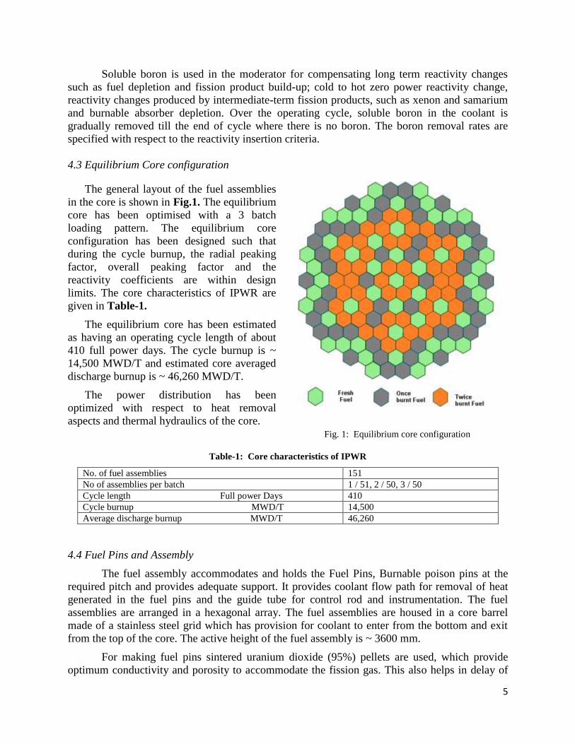
The general layout of the fuel assemblies
in the core is shown in Fig.1. The equilibrium
core has been optimised with a 3 batch
loading pattern. The equilibrium core
configuration has been designed such that
during the cycle burnup, the radial peaking
factor, overall peaking factor and the
reactivity coefficients are within design
limits. The core characteristics of IPWR are
given in Table-1.
The equilibrium core has been estimated
as having an operating cycle length of about
410 full power days. The cycle burnup is ~
14,500 MWD/T and estimated core averaged
discharge burnup is ~ 46,260 MWD/T.
The power distribution has been
optimized with respect to heat removal
aspects and thermal hydraulics of the core. Fig. 1: Equilibrium core configuration
Table-1: Core characteristics of IPWR
No. of fuel assemblies 151
No of assemblies per batch 1 / 51, 2 / 50, 3 / 50
Cycle length Full power Days 410
Cycle burnup MWD/T 14,500
Average discharge burnup MWD/T 46,260
4.4 Fuel Pins and Assembly
The fuel assembly accommodates and holds the Fuel Pins, Burnable poison pins at the
required pitch and provides adequate support. It provides coolant flow path for removal of heat
generated in the fuel pins and the guide tube for control rod and instrumentation. The fuel
assemblies are arranged in a hexagonal array. The fuel assemblies are housed in a core barrel
made of a stainless steel grid which has provision for coolant to enter from the bottom and exit
from the top of the core. The active height of the fuel assembly is ~ 3600 mm.
For making fuel pins sintered uranium dioxide (95%) pellets are used, which provide
optimum conductivity and porosity to accommodate the fission gas. This also helps in delay of
6
pellet clad interaction. Zr-1%Nb is used as clad material (~46,260 MWD/T burn-up) having
lower corrosion and hydrogen pick-up properties compared to other Zr-alloys.
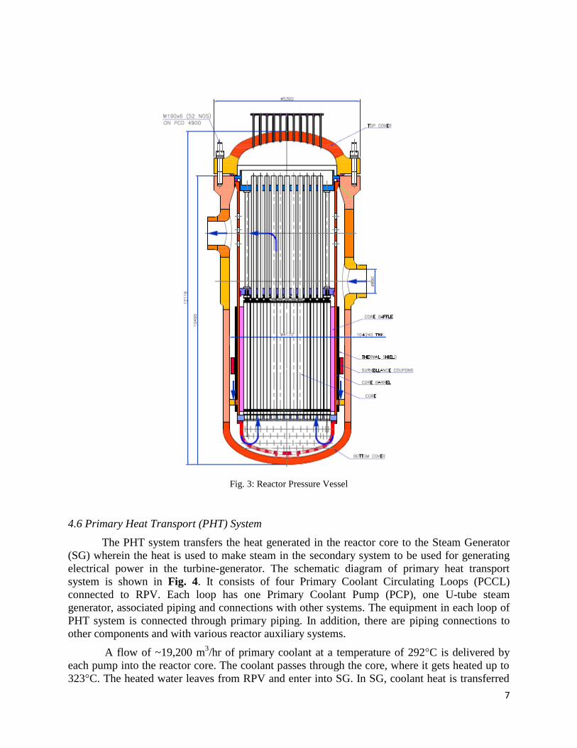
4.5 Reactor Pressure vessel
The Reactor Pressure Vessel (RPV) houses the heat generating reactor core and acts as a
boundary against the release of fuel fission products. It supports, locates & aligns the reactor
core and internals, and also properly locates & aligns the control rod drive mechanisms and in-
core instrumentations. The vessel is designed and manufactured to the requirements of Section
III-NB for class-1 components of the ASME Boiler and Pressure Vessel Code. The main
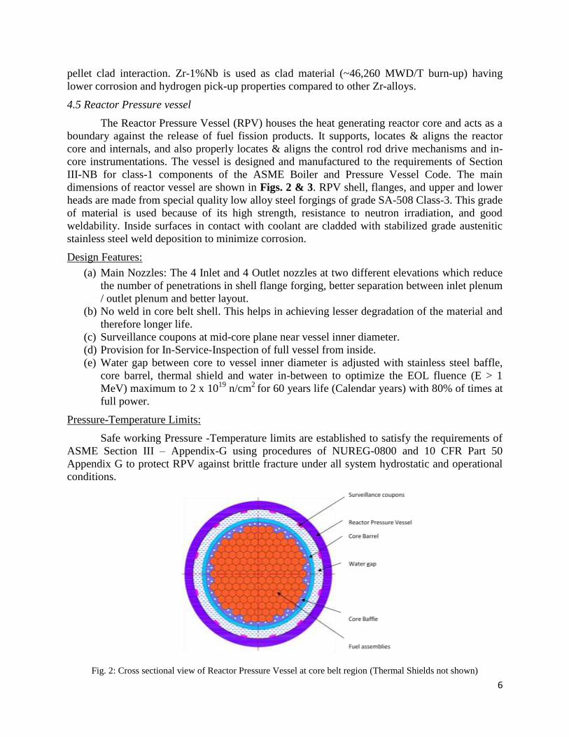
dimensions of reactor vessel are shown in Figs. 2 & 3. RPV shell, flanges, and upper and lower
heads are made from special quality low alloy steel forgings of grade SA-508 Class-3. This grade
of material is used because of its high strength, resistance to neutron irradiation, and good
weldability. Inside surfaces in contact with coolant are cladded with stabilized grade austenitic
stainless steel weld deposition to minimize corrosion.
Design Features:
(a) Main Nozzles: The 4 Inlet and 4 Outlet nozzles at two different elevations which reduce
the number of penetrations in shell flange forging, better separation between inlet plenum
/ outlet plenum and better layout.
(b) No weld in core belt shell. This helps in achieving lesser degradation of the material and
therefore longer life.
(c) Surveillance coupons at mid-core plane near vessel inner diameter.
(d) Provision for In-Service-Inspection of full vessel from inside.
(e) Water gap between core to vessel inner diameter is adjusted with stainless steel baffle,
core barrel, thermal shield and water in-between to optimize the EOL fluence (E > 1
MeV) maximum to 2 x 10¹⁹
n/cm2
for 60 years life (Calendar years) with 80% of times at
full power.
Pressure-Temperature Limits:
Safe working Pressure -Temperature limits are established to satisfy the requirements of
ASME Section III – Appendix-G using procedures of NUREG-0800 and 10 CFR Part 50
Appendix G to protect RPV against brittle fracture under all system hydrostatic and operational
conditions.
Fig. 2: Cross sectional view of Reactor Pressure Vessel at core belt region (Thermal Shields not shown)
7
Fig. 3: Reactor Pressure Vessel
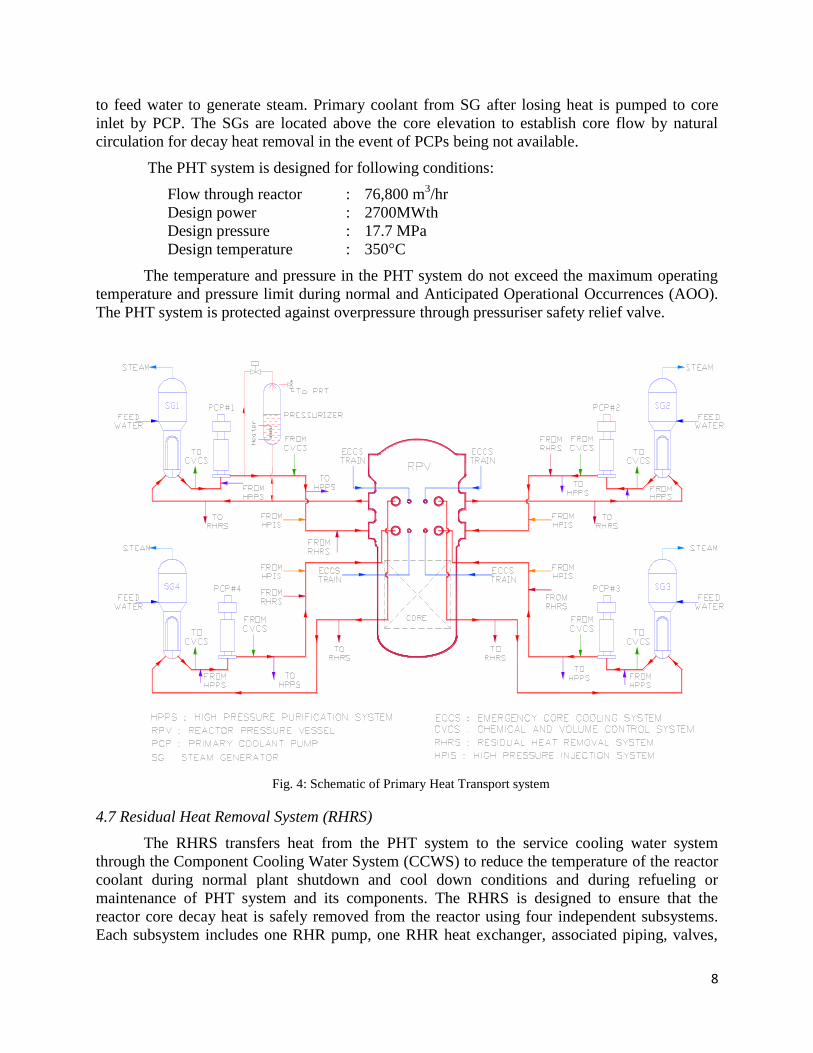
4.6 Primary Heat Transport (PHT) System
The PHT system transfers the heat generated in the reactor core to the Steam Generator
(SG) wherein the heat is used to make steam in the secondary system to be used for generating
electrical power in the turbine-generator. The schematic diagram of primary heat transport
system is shown in Fig. 4. It consists of four Primary Coolant Circulating Loops (PCCL)
connected to RPV. Each loop has one Primary Coolant Pump (PCP), one U-tube steam
generator, associated piping and connections with other systems. The equipment in each loop of
PHT system is connected through primary piping. In addition, there are piping connections to
other components and with various reactor auxiliary systems.
A flow of ~19,200 m3/hr of primary coolant at a temperature of 292°C is delivered by
each pump into the reactor core. The coolant passes through the core, where it gets heated up to
323°C. The heated water leaves from RPV and enter into SG. In SG, coolant heat is transferred
8
to feed water to generate steam. Primary coolant from SG after losing heat is pumped to core
inlet by PCP. The SGs are located above the core elevation to establish core flow by natural
circulation for decay heat removal in the event of PCPs being not available.
The PHT system is designed for following conditions:
Flow through reactor : 76,800 m3/hr
Design power : 2700MWth
Design pressure : 17.7 MPa
Design temperature : 350°C
The temperature and pressure in the PHT system do not exceed the maximum operating
temperature and pressure limit during normal and Anticipated Operational Occurrences (AOO).
The PHT system is protected against overpressure through pressuriser safety relief valve.
Fig. 4: Schematic of Primary Heat Transport system
4.7 Residual Heat Removal System (RHRS)
The RHRS transfers heat from the PHT system to the service cooling water system
through the Component Cooling Water System (CCWS) to reduce the temperature of the reactor
coolant during normal plant shutdown and cool down conditions and during refueling or
maintenance of PHT system and its components. The RHRS is designed to ensure that the
reactor core decay heat is safely removed from the reactor using four independent subsystems.
Each subsystem includes one RHR pump, one RHR heat exchanger, associated piping, valves,
9
and instrumentation necessary for operational control. Any two of the four subsystems have a
100% capability for safe shutdown heat removal.
4.8 Chemical and Volume Control System (CVCS)
This is a major reactor auxiliary system of PHT system. The functions of the system are
to maintain required water inventory in PHT system as required by the Pressuriser level
controller, to control the concentration of boric acid in the primary coolant and to provide
purification of coolant through purification ion exchangers. Besides these function, the system is
also used to add chemicals in primary coolant, to give seal injection water to seals of PCPs and
to give auxiliary spray to pressuriser. It consist of a Regenerative Heat Exchanger (RHX), Non-
Regenerative Heat Exchanger (NRHX), filters, ion exchangers, two charging pumps, Volume
Control Tank (VCT), piping and valves. Hydrogen atmosphere is maintained in VCT to control
the concentration of H2 in the PHT coolant. CVCS consists of various subsystems for reactor
coolant storage, boron recycling and boric acid storage.
During normal operation nominal flow is maintained as required for purification.
However, the flow varies during boric acid addition or removal from primary coolant for power
control.
4.9 Fuel pool cooling and purification system
The fuel pool cooling and purification system removes the decay heat generated by the
spent fuel clusters; maintains uniform temperature in the storage bay water (32°C to 35°C),
filters out the suspended impurities for good visibility of bay water and provides adequate water
shielding for working personnel. The fuel storage pool is located inside reactor building and the
Fuel Storage Bay (FSB) is located inside fuel building, outside the reactor containment. These
two bays are connected through fuel transfer tube. FSB is provided for under water storage of
spent fuel and new fuel. Storage capacity of ~ 10 years is provided. Fuel clusters are stored
vertically in rack. Water shielding of 10 m above the rack in fuel-stored condition is maintained.
Minimum water shielding of 5 m (approx.) is maintained during movement of fuel cluster to
maintain minimum acceptable radiation level.
5. Reactor Safety System
Reactor safety system reduces the consequences of postulated accidents. Ultimate aim of
the system is to ensure public safety in the unlikely event of an accidental release of radioactivity
from the Reactor Coolant System (RCS). The engineered safety system will automatically act to
limit, control, and terminate unplanned events, while maintaining the radiation exposure to the
public well below the applicable regulatory limits and guidelines.
5.1 Reactor Shut-down Systems
IPWR has independent quick and reliable fail safe shut down system. Reactor shut down
system is designed to immediately terminate the nuclear chain reaction and maintain the sub-
criticality for prolonged period of time. IPWR has the following reactor shutdown systems:
a) Reactor Control and Shut-off Rod Drive Mechanism (CSRDM) - These are a series of
solid absorber rods that can be quickly inserted into the core (through control rod guide
tubes) to absorb neutrons and rapidly terminate the nuclear reaction. The magnetic jack
10
type control and shut off mechanism is used for controlling and shutting down the
reactor. It can hold the absorber at fixed position or release it fast for quick shutdown.
b) Liquid Boron Injection System (LBIS) - This is an alternate mode to shut down the
reactor in Anticipated Transient Without Scram (ATWS) scenario. The nuclear reaction
is stopped by directly injecting a liquid poison (boric acid solution) into the core that
absorbs neutrons. This system is very effective during power excursion accident like Loss
Of Regulation Accident (LORA). The system is designed to automatically introduce
sufficient negative reactivity in few seconds on detection of ATWS event.
5.2 Emergency Core Cooling System (ECCS)
The primary function of the ECCS is to deliver emergency core cooling in the event
when primary coolant system is accidentally depressurized (i.e., a LOCA). The defense-in-depth
philosophy in terms of functional diversity, passive safety system, redundancy, independent
safety trains and fail safe design are incorporated. The system has four physically separated and
independent channels. The design criteria considers full spectrum of break sizes including a
break equivalent in size to the double ended guillotine break (DEGB) of the largest pipe in the
reactor coolant system. Flow Restriction Orifices (FROs) are used in Pressurizer surge line,
Purification line and other auxiliary system pipe lines to minimize blow down. The hydro
accumulator’s volume is selected on the basis that it should flood entire core at least 10 times.
The ECCS water is injected into core through cold leg and hot leg with 2x100% dedicated direct
pipe lines in each legs.
5.3 Passive Decay Heat Removal System (PDHRS)
This system removes decay heat from core continuously by natural recirculation of the
inventory on secondary side of SGs in the event of total loss of power supply. Four number
independent loops work simultaneously, each consisting of one water filled expansion tank of
50m3 capacity and two vertical emergency heat exchangers, connected to individual SG’s. The 8
numbers of emergency heat exchangers are kept submerged in two cooling water tanks each of
5000m3 capacity. The steam from SG is passed through water cooled HXs and condensate
returns back to SG. Steam pressure in expansion tanks is used to push water to SG feed line. The
water in the cooling water tanks acts as a heat sink. The capacity of the cooling water tanks is
designed in such a manner to enable passive cooling for a period of minimum seven (7) days
from the initiation of the event.
5.4 Core catcher (Molten Pool Retention System)
In IPWR design a corium retention system is provided. The in-vessel retention system
has a water flooding provision outside RPV following an accident requiring cooling of core for
removal of decay heat. In case a core melt happens, the core heat is removed through RPV body
by formation of steam of the flooded water outside.
6. Instrumentation and Control
The function of the instrumentation and control system in IPWR is to provide capability
to control, monitor and regulate the plant systems during normal operation of the plant and
protect the reactor against unsafe plant operation. The I&C systems also provides initiating
signals to actuate safety functions which are assigned to mitigate the consequences of accident
conditions and ensure safe shut down of the reactor. The design includes concepts on defense-in-

11
depth and Diversity, Single Failure Criterion, Redundancy, Physical separation Isolation and
Functional Independence, Equipment Qualification and Protection, Unified Architecture, Self-
Diagnostics Functions and Human-System Interface, etc. The overall I&C are such that all the
safety functions are normally achievable from Main Control Room (MCR). In case MCR is
inhabitable then all the safety functions can be carried out from Back-up Control room (BCR).
The MCR is designed to perform centralized monitoring and control of I&C systems that are
necessary for use during normal plant operation, AOOs, and PIEs. HSIS are also designed to
reduce the potential for human errors and to allow easy operation by adopting sound Human
Engineering principles with adequate intelligence in its design. Independent sensor and analogue
systems are provided for assuring reactor trip when design trip signal is exceeded.
7. Radiological Protection
Accessible areas in the station are divided into areas according to the radiation potential.
The Accessible and Shutdown Areas are clearly distinguished. The Shutdown Areas have doors
and interlock system to ensure that inadvertent personnel entries in these areas are avoided. Entry
to other locations of high radiation potential is restricted by administrative control. In order to
minimise contamination and also to control its spread, the entire plant area is divided into four
distinct zones of different contamination potential. Each zone is clearly demarcated and provided
with inter-zonal check points equipped with contamination monitors. The personnel movement to the
plant is arranged from zones of lower to higher contamination potential for entry and vice versa for
exit. At the final exit point (zone 2 to zone 1 interface) automatic portal surveillance monitor is
installed.
For demonstrating compliance with prescribed limits and providing information on
changes in radiation levels, radiation monitoring system is provided in the plant. Monitoring
includes individual, workplace and environmental monitoring. Individual external and internal
monitoring for the occupational workers will be carried out on a routine basis. Workplace
monitoring will be done for external radiation, airborne contamination and surface
contamination. Monitoring for protection of the public includes monitoring of effluents from the
plant as well as environmental monitoring during normal operation and accident conditions.
The on-site / off-site radiation emergency planning is incorporated to ensure adequate
preparedness for protection of the plant personnel and members of the public from significant
radiation exposures in the unlikely event of an accident. The probability of an accident though
brought to a very low level by incorporating defense-in-depth approach, however, can never be
reduced to absolute zero and therefore this residual risk is sought to be mitigated by appropriate
siting criteria and implementing suitable arrangements for emergency planning and
preparedness.
8. Safety Classification
In IPWR, the Structures, Systems, and Components (SSCs) are graded and classified
according to the role played by them in the measures to control radiological hazards. Based on
the classification, their design requirements are accordingly established without compromising
the overall safety objective. This is achieved by identifying the different safety functions
performed by individual SSCs in terms of their role in achieving the safety objective. These
safety functions are then grouped and ranked into safety classes, taking into consideration the
consequences of failure of the safety function performed by SSC and the probability of
occurrence of a failure.
12
9. Nuclear Security
Nuclear Security in IPWR will incorporate comprehensive technical, operating and
administrative measures which in association with nuclear safety measures will address any
possible potential threats of theft and sabotage by an external as well as insider adversary.
IPWR is provided with comprehensive Integrated Physical Protection System (IPPS)
backed up by strong administrative and operational measures which will be designed to address
site specific design basis threats (DBT). The security system of the plant will be operational at all
the time and for all credible scenarios. It is designed to perform the functions of detection, delay,
assessment and response as applicable to IPWR. The system provides adequate protection
following a multilayered architecture providing defense-in-depth, balance protection, graded
approach, tolerance to component failures using diversity and redundancy. Technical measures
for IPWR nuclear security includes multi-layered security arrangement whereby the most vital
and important areas / facilities are placed in the innermost layer.
10. Acknowledgement
The design and development of IPWR plant is a joint work of a group of engineers and
scientists working at Bhabha Atomic Research Centre (BARC) and Nuclear Power Corporation
of India Limited (NPCIL). The author acknowledges the effort put up by all these engineers and
scientists for their valuable contributions.
11. References
11.1 Conceptual design report of Indian PWR (IPWR) by R N Sen et. el. – Report No.
BARC/IPWR/RPG/09/2013/Rev.0, Sept-2013.
11.2 Detailed Project Report on 900 MWe Indian PWR (IPWR) by R N Sen et. el. – Report
No.: BARC-NPCIL/IPWR/10/2014/Rev.0, July-2014.