1 introduction 2 experimental details - uq espace - university of
TRANSCRIPT
Mechanical Properties and Removal Characteristic of Cemented Tungsten Carbide with Fine Microstructure Studied by Nanoindentation and Nanoscratch Rudy Irwan1 and Han Huang1
1School of Engineering, the University of Queensland, Brisbane, QLD 4072, Australia
Abstract: Nanoindentation and nanoscratch were used to investigate mechanical properties and removal characteristics of cemented tungsten carbide (WC) with fine microstructure. The elastic modulus and hardness of WC grains were found to be significantly greater than the respective values measured in cobalt binder rich regions. Few evidences of cracking or fragmentation were observed on the indented surfaces using in-situ atomic force microscopy. Nevertheless, pop-in events were observed from the indentation load-displacement relationships and associated acoustic emission signals were detected. Nanoscratch experiments were conducted to explore the removal mechanisms of the cemented WC. It revealed that the removal of the WC material varied from plastic deformation to fractured when the scratching load was increased. The scratching load and speed affected the material removal rate.
Keywords: elastic modulus, fracture, hardness, nanoindentation, nanoscratch, tungsten carbide
1 Introduction Tungsten carbide (WC) is a material of great technological interests due to its excellent mechanical properties [1], such as high hardness, corrosion resistance, chemical stability and high-temperature wear resistance. Cemented WC with fine microstructure is commonly used for making glass moulding dies or mould inserts. The fabrication of such mould inserts is usually via microgrinding [2].
Microgrinding is a grinding process that has a material removal unit at nanometric scale and is capable to machine components with feature size ranging from several to several hundreds microns [3]. The machine components are of high dimensional accuracy and high surface and subsurface integrity. In particular, when grinding a brittle material, the grinding process must be conducted in the ductile removal regime of the material. To successfully develop a ductile grinding process, it is essential to gain deep understanding of work material and the interaction between the cutting abrasive and the work material. This requires systematic investigations to the mechanical properties of the material and the effect of its microstructure on deformation and removal under microgrinding [4-5].
Nanoindentation has been extensively used as a tool to study the mechanical properties of materials [6], in particular for those materials with fine microstructure where highly localized properties need to be measured [7-10]. This is because a nanoindentation event is closely analogous to the penetration of a diamond abrasive grit into the specimen surface during nanogrinding. Similarly, nanoscratch that is analogous to a single-grit scratching event in a nanogrinding process is the most convenient method to study material removal involved in grinding at nanometric scale. Nanoscratch was used to investigate fundamental microstructure fracture in brittle materials [11-12] and the mechanisms of material removal during grinding, including plastic deformation, microstructure damage and fracture [13]. Previous studies showed that great efforts were directed towards investigating material fracture, wear and friction coefficient. Most of the studies were on thin films [14], but little was reported on brittle materials with fine microstructures.
This study investigated mechanical properties and deformation characteristics of cemented WC using the nanoindentation and nanoscratch methods. Hardness (H) and elastic modulus (E) of the WC grains and binder areas were measured. Topographies of impressions were examined using in-situ atomic force microscope (AFM). Pop-in events from indenting processes were monitored using an AE sensor. Scanning electron microscope (SEM) was employed to examine WC microstructure changes.
2 Experimental Details
2.1 Tungsten carbide specimen Cemented WC with fine microstructure (Toshiba Tangaloy, Japan) is the work material in this study. Cemented WC, also named as �hard metal�, is a material made by cementing hard tungste n mono-
carbide (WC) grains in a binder matrix of cobalt metal by liquid phase sintering [15]. The nominal Young�s modulus of the bulk material is 560 GPa [15]. Microhardness was measured using a Mitutoyo microhardness tester, and the value for the material is 18.1 GPa.
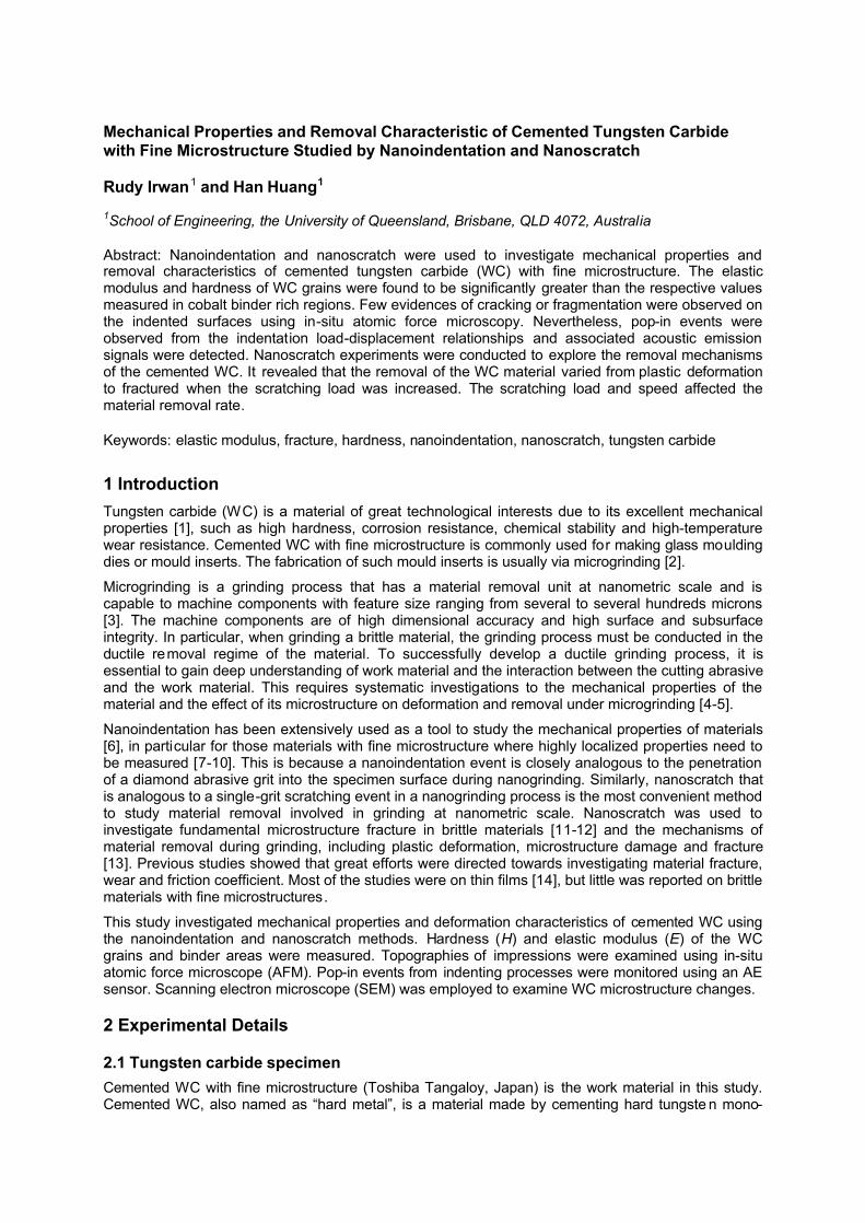
The specimens were polished using diamond lapping films of grit sizes down to 0.5 µm. The final polishing was carried out using silica suspension with particle size 0.1 µm on a soft pad. After polishing, WC grains were clearly exposed. As shown in Figure 1, it is seen that the microstructure consists of WC grains (grey phase) and cobalt binder (black phase). The WC grains have shapes of nearly triangle, rectangular and trapezoidal, with sizes ranging from ~200 nm to ~1 µm.
Figure 1. Microstructure of WC consists of grains (grey phase) and cobalt binders (black phase).
2.2 Nanoindentation test Nanoindentation experiments were conducted on a Hysitron Triboindenter® nanomechanical testing instrument. For measuring mechanical properties, a three-sided Berkovich indenter with a tip radius of 100 nm was used. The loads of indentation used were ranging from 500 µN to 30 mN. Indentation was purposely made on the grain or binder-rich regions. In-situ AFM was used to examine the surface topographies prior to and after indentation.
Determination of reduced elastic modulus, Er, and hardness was undertaken from the initial part of the unloading segment from each indentation load-displacement curve [6], over the indenter penetration depths. The elastic modulus of the material, E, was computed using the reduced elastic modulus measured from nanoindentation using the following equation:
22 11 1 i
r i
vvE E E
−−= +
(1)
Where Ei = 1141 GPa, υi = 0.07 are the elastic modulus and the Poisson�s ratio of the diamond tip, and υ = 0.27 was used for WC [15]. For monitoring the fracture events during indentation, a 90o cube corner diamond tip was employed, with an embedded acoustic emission (AE) sensor. To reduce the noise effect and get the appropriate detection of AE signals, a threshold of 69 dB was preset.
2.3 Nanoscratch test Nanoscratch experiments were also conducted on the Hysitron Triboindenter®. A conical diamond indenter with a 3 µm tip radius was used. The scratching was carried out at a linear velocity to up to 1 µm/s, and with maximum scratching length of 12 µm. Both normal and lateral forces were recorded. Normal loads ranged from 500 µN to 5 mN.
Both top and cross-sectional surfaces of the scratches were examined using a SEM (JEOL 6300 LA). For the cross-sectional surface examination, a bonded-interface sectioning procedure [12] was used. Two polished surfaces were bonded together using �super glue� adhesive and then were clamped, leaving a thin layer of glue, approximately 1 µm thickness. The top surface for scratching was then polished. Nanoscratches were made perpendicular to the interface. A constant normal load of 5 mN and a scratching rate of 1 µm/s were employed. After scratching, the adhesive joining the interfaces was dissolved in acetone. Separated samples were carbon coated for SEM examination.
3. Result and Discussion
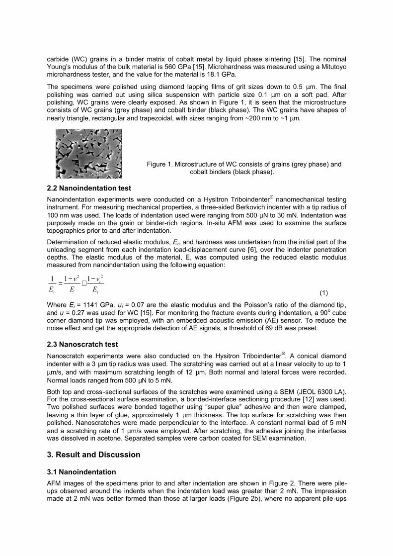
3.1 Nanoindentation AFM images of the specimens prior to and after indentation are shown in Figure 2. There were pile-ups observed around the indents when the indentation load was greater than 2 mN. The impression made at 2 mN was better formed than those at larger loads (Figure 2b), where no apparent pile-ups
were observed. A greater indentation loads used resulted in a larger pile-up, as can be seen from the AFM images in Figures 2d. There were no obvious cracks observed from the AFM examination, for loads up to 30 mN. It should be noted that the threshold load of 2 mN for the pile-up occurrence was obtained from the indentations made on the tungsten carbide grains. If the indentation was made on the binder-rich region, the threshold load for piling-up should be smaller. There was also a pile-up formed in the binder area.
Figure 2. AFM images of surfaces (a) prior to and (b) after indentation at 2 mN; (c) prior to and (d)
after indentation at 12 mN; Images (a) and (b) have a scan size of 2×2 µm, and (c) and (d) in 3×3 µm.
Table 1. Elastic modulus and hardness values
Values of E and H obtained from the nanoindentation tests are listed in Table 1.The results in Table 1 suggest that the elastic modulus of the WC grains is significantly higher than that in the binder-rich areas. As mentioned in Section 2, the cemented WC consists of WC grains (the stronger phase in the material) and cobalt binders (the weaker phase in the material). Therefore, it is expected that the bulk modulus should be smaller than the modulus of the WC grains, but greater than that of the binder-rich material. It is seen that the hardness for the WC grains are greater than that measured in the binder rich regions, which is similar to the modulus results. However, the hardness values measured in the binder rich region are slightly greater than the nominal value. For the measurements conducted in the binder-rich region, the hardness was slightly affected by the load. When the indentation load was greater, the indent would cover more WC grains and the influence of the grains was thus larger, resulting in a slightly larger hardness. The results also suggest that the local hardness is more sensitive to the microstructure than elastic modulus.
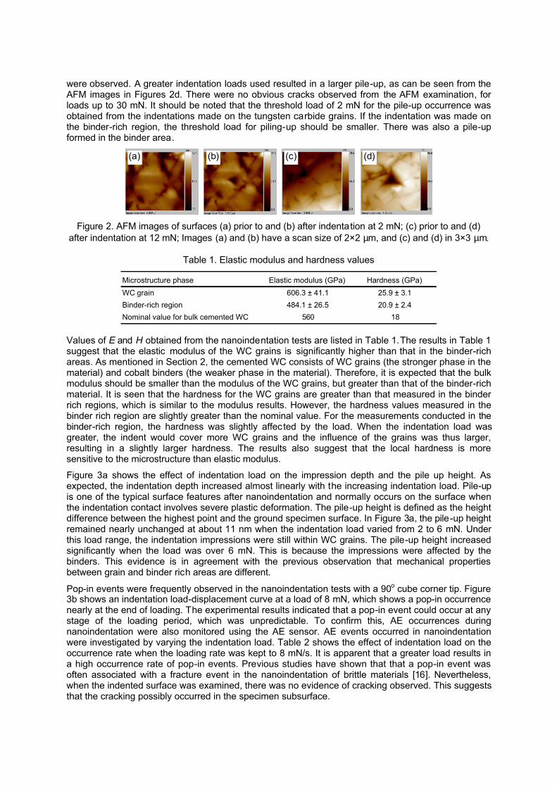
Figure 3a shows the effect of indentation load on the impression depth and the pile up height. As expected, the indentation depth increased almost linearly with the increasing indentation load. Pile-up is one of the typical surface features after nanoindentation and normally occurs on the surface when the indentation contact involves severe plastic deformation. The pile-up height is defined as the height difference between the highest point and the ground specimen surface. In Figure 3a, the pile-up height remained nearly unchanged at about 11 nm when the indentation load varied from 2 to 6 mN. Under this load range, the indentation impressions were still within WC grains. The pile-up height increased significantly when the load was over 6 mN. This is because the impressions were affected by the binders. This evidence is in agreement with the previous observation that mechanical properties between grain and binder rich areas are different.
Pop-in events were frequently observed in the nanoindentation tests with a 90o cube corner tip. Figure 3b shows an indentation load-displacement curve at a load of 8 mN, which shows a pop-in occurrence nearly at the end of loading. The experimental results indicated that a pop-in event could occur at any stage of the loading period, which was unpredictable. To confirm this, AE occurrences during nanoindentation were also monitored using the AE sensor. AE events occurred in nanoindentation were investigated by varying the indentation load. Table 2 shows the effect of indentation load on the occurrence rate when the loading rate was kept to 8 mN/s. It is apparent that a greater load results in a high occurrence rate of pop-in events. Previous studies have shown that that a pop-in event was often associated with a fracture event in the nanoindentation of brittle materials [16]. Nevertheless, when the indented surface was examined, there was no evidence of cracking observed. This suggests that the cracking possibly occurred in the specimen subsurface.
Microstructure phase Elastic modulus (GPa) Hardness (GPa)WC grain 606.3 ± 41.1 25.9 ± 3.1Binder-rich region 484.1 ± 26.5 20.9 ± 2.4Nominal value for bulk cemented WC 560 18
(a) (b) (c) (d)
0
50
100
150
200
0
50
100
150
200
0 5 10 15 20 25 30
Pile-UpDepth
Pile
-up
(nm
)
Dep
th (n
m)
Indentation Load (mN)
0
1000
2000
3000
4000
5000
6000
7000
8000
0 50 100 150 200 250 300
Inde
ntat
ion
Load
(µN
)
Displacement (nm)
Pop-in
Figure 3. (a) Pile-up height (rectangles) and indentation depth (circles); (b) Pop-in event associated
with indentation process at indentation load of 8 mN.
Table 2. Pop-in occurrence rates for various indentation loads and a constant loading rate 8 µN/s
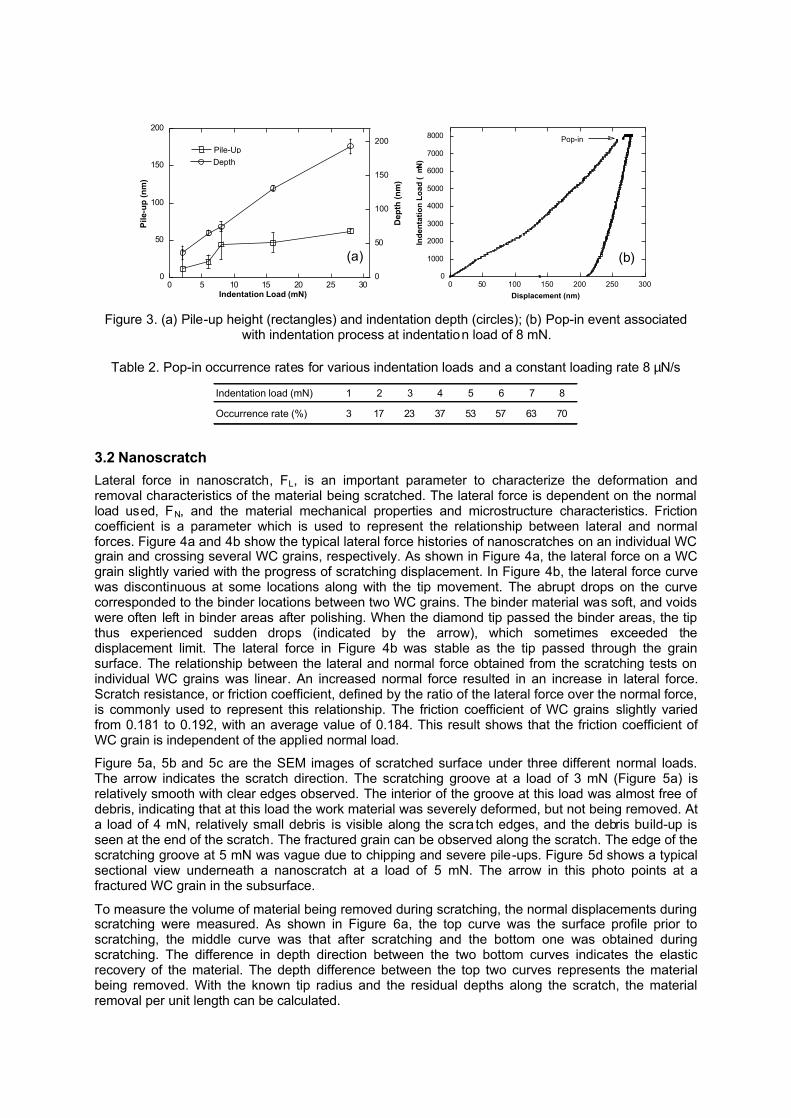
3.2 Nanoscratch Lateral force in nanoscratch, FL, is an important parameter to characterize the deformation and removal characteristics of the material being scratched. The lateral force is dependent on the normal load used, FN, and the material mechanical properties and microstructure characteristics. Friction coefficient is a parameter which is used to represent the relationship between lateral and normal forces. Figure 4a and 4b show the typical lateral force histories of nanoscratches on an individual WC grain and crossing several WC grains, respectively. As shown in Figure 4a, the lateral force on a WC grain slightly varied with the progress of scratching displacement. In Figure 4b, the lateral force curve was discontinuous at some locations along with the tip movement. The abrupt drops on the curve corresponded to the binder locations between two WC grains. The binder material was soft, and voids were often left in binder areas after polishing. When the diamond tip passed the binder areas, the tip thus experienced sudden drops (indicated by the arrow), which sometimes exceeded the displacement limit. The lateral force in Figure 4b was stable as the tip passed through the grain surface. The relationship between the lateral and normal force obtained from the scratching tests on individual WC grains was linear. An increased normal force resulted in an increase in lateral force. Scratch resistance, or friction coefficient, defined by the ratio of the lateral force over the normal force, is commonly used to represent this relationship. The friction coefficient of WC grains slightly varied from 0.181 to 0.192, with an average value of 0.184. This result shows that the friction coefficient of WC grain is independent of the applied normal load.
Figure 5a, 5b and 5c are the SEM images of scratched surface under three different normal loads. The arrow indicates the scratch direction. The scratching groove at a load of 3 mN (Figure 5a) is relatively smooth with clear edges observed. The interior of the groove at this load was almost free of debris, indicating that at this load the work material was severely deformed, but not being removed. At a load of 4 mN, relatively small debris is visible along the scra tch edges, and the debris build-up is seen at the end of the scratch. The fractured grain can be observed along the scratch. The edge of the scratching groove at 5 mN was vague due to chipping and severe pile-ups. Figure 5d shows a typical sectional view underneath a nanoscratch at a load of 5 mN. The arrow in this photo points at a fractured WC grain in the subsurface.
To measure the volume of material being removed during scratching, the normal displacements during scratching were measured. As shown in Figure 6a, the top curve was the surface profile prior to scratching, the middle curve was that after scratching and the bottom one was obtained during scratching. The difference in depth direction between the two bottom curves indicates the elastic recovery of the material. The depth difference between the top two curves represents the material being removed. With the known tip radius and the residual depths along the scratch, the material removal per unit length can be calculated.
Indentation load (mN) 1 2 3 4 5 6 7 8
Occurrence rate (%) 3 17 23 37 53 57 63 70
(a) (b)
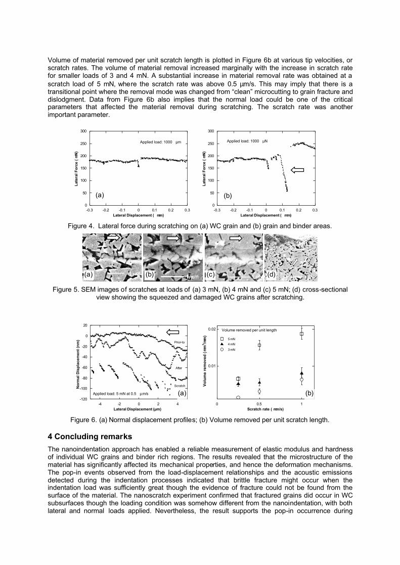
Volume of material removed per unit scratch length is plotted in Figure 6b at various tip velocities, or scratch rates. The volume of material removal increased marginally with the increase in scratch rate for smaller loads of 3 and 4 mN. A substantial increase in material removal rate was obtained at a scratch load of 5 mN, where the scratch rate was above 0.5 µm/s. This may imply that there is a transitional point where the removal mode was changed from �clean� microcutting to grain fracture and dislodgment. Data from Figure 6b also implies that the normal load could be one of the critical parameters that affected the material removal during scratching. The scratch rate was another important parameter.
0
50
100
150
200
250
300
-0.3 -0.2 -0.1 0 0.1 0.2 0.3
Applied load: 1000 µm
Late
ral F
orce
(µ
N)
Lateral Displacement ( µm)
0
50
100
150
200
250
300
-0.3 -0.2 -0.1 0 0.1 0.2 0.3
Applied load: 1000 µN
K
Late
ral F
orce
(µ
N)
Lateral Displacement ( µm) Figure 4. Lateral force during scratching on (a) WC grain and (b) grain and binder areas.
Figure 5. SEM images of scratches at loads of (a) 3 mN, (b) 4 mN and (c) 5 mN; (d) cross-sectional
view showing the squeezed and damaged WC grains after scratching.
-120
-100
-80
-60
-40
-20
0
20
-4 -2 0 2 4
Applied load: 5 mN at 0.5 µm/s
Nor
mal
Dis
plac
emen
t (nm
)
Lateral Displacement (µm)
Scratch
Prior-to
After 0.01
0.02
0 0.5 1
Volume removed per unit length
5 mN4 mN
3 mN
Volu
me
rem
oved
(µ
m3 /µ
m)
Scratch rate ( µm/s) Figure 6. (a) Normal displacement profiles; (b) Volume removed per unit scratch length.
4 Concluding remarks The nanoindentation approach has enabled a reliable measurement of elastic modulus and hardness of individual WC grains and binder rich regions. The results revealed that the microstructure of the material has significantly affected its mechanical properties, and hence the deformation mechanisms. The pop-in events observed from the load-displacement relationships and the acoustic emissions detected during the indentation processes indicated that brittle fracture might occur when the indentation load was sufficiently great though the evidence of fracture could not be found from the surface of the material. The nanoscratch experiment confirmed that fractured grains did occur in WC subsurfaces though the loading condition was somehow different from the nanoindentation, with both lateral and normal loads applied. Nevertheless, the result supports the pop-in occurrence during
(a) (b)
(a) (b) (c) (d)
(a) (b)
nanoindentation. This study also suggests that the nanoscratch approach is an important method to study material removal mechanisms involving in a nanogrinding process.
5 Acknowledgement The authors are grateful to acknowledge the financial support by the Australia Research Council (ARC) under Discovery Project Grant DP0557349.
6 References [1] W.A. Weimer (Ed.), Carbide, Nitride and Boride Materials-Synthesis and Processing, Chapman & Hall,
London, 1997.
[2] Chen, W.K., Kuriyagawa, T., Huang, H. and Yosihara, N. (2005), Machining of micro aspherical mould inserts, Precision Engineering, 29, 315-323.
[3] Masuzawa, T. and Tönshoff, H.K. (1997), Three-dimensional micromachining by machine tools, Annals of CIRP, 46/2, 621-628.
[4] Zarudi, I., Zhang, L. and Cockayne, D. (1998), Subsurface structure of alumina associated with single-point scratching, Journal of Materials Science, 33, 1639-1654
[5] Yin, L., Spowage, A. C., Ramesh, K., Huang, H., Pickering, J.P. and Vancoille, E.Y. J. (2004), Influence of microstructure on ultraprecision grinding of cemented carbides: International Journal of Machine Tools and Manufacture, 44, 533-543.
[6] Oliver, W.C. and Pharr, G.M. (2004), Measurement of hardness and elastic modulus by instrumented indentation: Advances in understanding and refinements to methodology, Journal of Materials Research, 19, 3-20.
[7] Vodenitcharova T. and Zhang L. (2003), A mechanics prediction of the behaviour of mono-crystalline silicon under nano-indentation, International Journal of Solids and Structures , 40, 2989-2998.
[8] Schoberl, T., Gupta, H.S. and Fratzl, P. (2003), Measurement of mechanical properties in Ni-based superalloys using nanoindentation and atomic force microscopy, Materials Science and Engineering, A363, 211-220.
[9] Huang, H. and Kuriyagawa, T. (2005), Effect of microstructure on material removal mechanisms in nano/micro grinding of tungsten carbide mould inserts, Proceedings of the International Conference on Leading Edge Manufacturing in 21st Century (Vol. 2), Nagoya, Japan, 20-22 October 2005, 877-882.
[10] Huang, H., Irwan, R. and Kuriyagawa, T. (2007), A study on deformation and removal mechanisms of tungsten carbide using nanoindentation, Key Engineering Materials, 329, 385-390.
[11] Subash, G. and Bandyo, R. (2005), A new scratch resistance measure for structural ceramics, Journal of American Ceramic Society, 88, 918-925.
[12] Xu, H.K.K. and Jahanmir, S. (1994), Simple technique for observing damage in machining ceramics, Journal of American Ceramic Society, 77, 1388-1390.
[13] Beake, B.D. and Ranganathan, N. (2006), An investigation of the nanoindentation and nano/micro-tribological behaviour of monolayer, bilayer and trilayer coatings on cemented carbide, Materials Science and Engineering A , 423, 46-51.
[14] Tayebi, N., Conry, T.F. and Polycarpou, A.A. (2003), Determination of hardness from nanoscratch experiments: Corrections for interfacial shear stress and elastic recovery, Journal of Material Research, 18, 2150-2162.
[15] Upadhyaya, G.S., Cemented Tungsten Carbides: Production, Properties and Testing, Texas, 2005.
[16] Tymiak, N.I., Daugela, A., Wyrobrek, T.J. and Warren, O.L. (2003), Highly localized acoustic emission monitoring of nanoscale indentation contacts, Journal of Materials Research, 18, 784-796.