1. general information - fluid transfer international ltd · filter differential pressure gauge –...
TRANSCRIPT

Nailsworth Mills Estate • Avening Road • Nailsworth • Gloucestershire • GL6 0BS • UK
T +44 (0)1453 833 381
F +44 (0)1453 833 529
3850 Litre/minute Hydrant Dispenser Specification APTUS OPTIMAS
– 1 –
KEY: – Standard – Option
1. GENERAL INFORMATION
The Hydrant Dispenser described in this specification is a truck mountedunit designed to pick up fuel from a hydrant pit. The basic vehicleconfiguration is with the elevating fuelling deck mounted immediately behindthe driver’s cab, the filter monitor over the rear axle and the hosereeltransversely mounted at the rear of the vehicle. The control station islocated on the driver’s side of the vehicle.
All pipework in the main system is constructed in Grade 304 stainless steeland is sized to reduce pressure loss to a minimum. Pipe joints are flanged,bends are smooth radiused type and all pipes are inert gas purged internallyduring welding.
Pipework and components have minimum working pressures of 10.2 bar(150 p.s.i.) and are pressure tested to 15.3 bar (225 p.s.i.).
The dispenser is fitted as standard with two pressure control systems,primary control being achieved at the delivery couplings via hose endpressure control valves, secondary control being achieved at the intakecoupling via a pressure control valve actuated by signal pressures receivedfrom venturis mounted in the delivery pipework.
The Ø100mm API type intake coupling is also fitted with a deadmanshutdown valve actuated by a hand held electric deadman switch attachedto a wanderlead.
The intake hose is stowed around the outside of the vehicle and is fittedwith hose trolleys which enable the hose to be positioned easily over theground. The intake coupling is stowed on the same side of the vehicle asthe control station.
Filtration is via an IP/API approved filter monitor manufactured in stainless steel.
Twin high flow deck hoses are provided and stowed on an elevating fuellingdeck. These can be used on large aircraft where it is possible to park thevehicle below the underwing mounted fuelling couplings.
28 Litre capacity shock alleviator can be fitted downstream of the meter.

Nailsworth Mills Estate • Avening Road • Nailsworth • Gloucestershire • GL6 0BS • UK
T +44 (0)1453 833 381
F +44 (0)1453 833 529
3850 Litre/minute Hydrant Dispenser Specification APTUS OPTIMAS
– 2 –
KEY: – Standard – Option
A single hosereel is provided and is fitted with a 30m long fuelling hose for stand-off fuelling duties. The hosereel is single volute (Catherine wheel)type mounted transversely across the back of the vehicle. It is fitted withguide roller box which enables easy hose pull-out and rewind.
The rewind system for the hosereel is hydraulically powered and is operatedby a lever operated control valve. The control valve incorporates 3 positions;‘free wheel, reel out’, ‘power rewind, reel in’ and ‘hosereel lock’. With theoperator in the locked position the hosereel rewind motor is hydraulicallylocked preventing the hosereel from rotating and therefore negating therequirement for an independent brake mechanism.
A single meter system is provided and records the volume of fuel deliveredthrough the deck hoses and the reel hose. It is fitted with a mechanicalregister / counter and rate of flow indicator.
All main structural members of the superstructure are constructed in boxsection steel which is shot blasted and etch primed, prior to theundercoating and finish painting process.
The dispenser is as standard, fitted with a pneumatic interlock systemacting on the chassis braking system.
Nailsworth Mills Estate • Avening Road • Nailsworth • Gloucestershire • GL6 0BS • UK
T +44 (0)1453 833 381
F +44 (0)1453 833 529
3850 Litre/minute Hydrant Dispenser Specification APTUS OPTIMAS
– 3 –
KEY: – Standard – Option
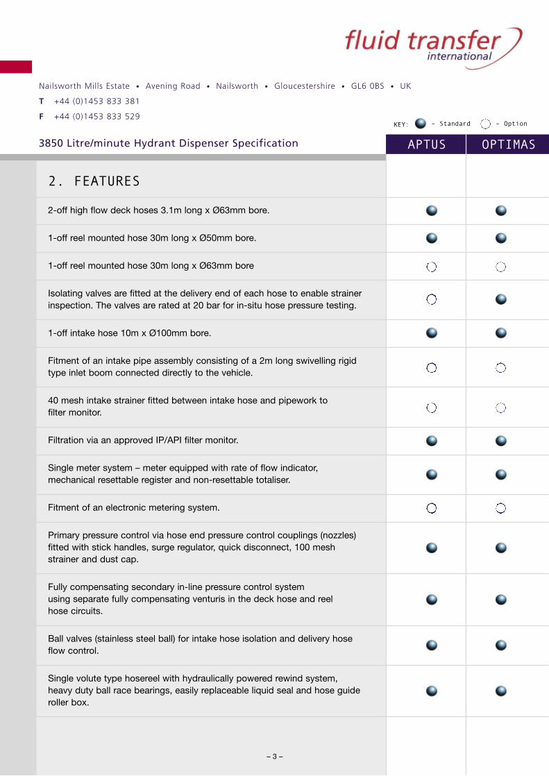
2. FEATURES
2-off high flow deck hoses 3.1m long x Ø63mm bore.
1-off reel mounted hose 30m long x Ø50mm bore.
1-off reel mounted hose 30m long x Ø63mm bore
Isolating valves are fitted at the delivery end of each hose to enable strainerinspection. The valves are rated at 20 bar for in-situ hose pressure testing.
1-off intake hose 10m x Ø100mm bore.
Fitment of an intake pipe assembly consisting of a 2m long swivelling rigidtype inlet boom connected directly to the vehicle.
40 mesh intake strainer fitted between intake hose and pipework to filter monitor.
Filtration via an approved IP/API filter monitor.
Single meter system – meter equipped with rate of flow indicator,mechanical resettable register and non-resettable totaliser.
Fitment of an electronic metering system.
Primary pressure control via hose end pressure control couplings (nozzles)fitted with stick handles, surge regulator, quick disconnect, 100 meshstrainer and dust cap.
Fully compensating secondary in-line pressure control system using separate fully compensating venturis in the deck hose and reel hose circuits.
Ball valves (stainless steel ball) for intake hose isolation and delivery hoseflow control.
Single volute type hosereel with hydraulically powered rewind system, heavy duty ball race bearings, easily replaceable liquid seal and hose guideroller box.

Nailsworth Mills Estate • Avening Road • Nailsworth • Gloucestershire • GL6 0BS • UK
T +44 (0)1453 833 381
F +44 (0)1453 833 529
3850 Litre/minute Hydrant Dispenser Specification APTUS OPTIMAS
– 4 –
KEY: – Standard – Option
Elevating fuelling deck – heavy duty maintenance free scissor lift adjustablein height between 1500mm and 4100mm with oil filled displacementcylinders and anti collapse valves. Fuelling deck is full vehicle width,1100mm long and is fitted with an aluminium open mesh strip type walkwaywhich does not cause damage to the fuelling hoses.
Fuelling deck bounded by 1000mm high stainless steel guard rails with kick-strip, intermediate rail and self closing gate. Deck access via aninclined ‘walk-up’ and ‘walk-down’ stairway and access landing areabounded by 1000mm high stainless steel guard rails, kick strip andintermediate rail. All access steps are constructed / covered in a non-slipmaterial. All control lines, hydraulic hoses etc. connecting the deck to thelower frame are protected from damage.
A ladder is fitted to allow descent from the deck when in the raised position.
The fuelling deck gate is mechanically locked in the closed position whenthe deck is in the elevated position.
The control valve for raising / lowering the deck is mounted in a shieldedlocation on the guard rails. Two emergency lowering valves are fitted, one adjacent to the above valve and one at ramp level. These valves can lower the deck withouthydraulic power.
An engine stop control valve (lock on type) is provided on the deck guard rails.
A bifurcated manifold attached to the rigid pipework via a swivel joint feedsdeck hoses. Design of the manifold ensures good hose support and easyhose handling. The deck can be fully lowered whilst the deck hoses remainconnected to the aircraft.
Fitment of a deck hose ‘Pantograph’ – this device enables shorter deckhoses to be fitted and raises automatically with the fuelling deck. When anozzle is unstowed the ‘Pantograph’ locks in the elevated position and will remain elevated even if the deck is lowered. The locking device isautomatically released when the nozzle is stowed and the ‘Pantograph’ will then retract with the deck as the deck is lowered.

Nailsworth Mills Estate • Avening Road • Nailsworth • Gloucestershire • GL6 0BS • UK
T +44 (0)1453 833 381
F +44 (0)1453 833 529
3850 Litre/minute Hydrant Dispenser Specification APTUS OPTIMAS
– 5 –
KEY: – Standard – Option
Intake coupling with integral pressure control and deadman valve and dust cap.
Intake and deck hose swivels are of the maintenance free (non-lubricated) type.
Intake hose fitted with robust hose trolleys and stowed around the perimeter of the vehicle.
Manually operated mechanical ‘easi-lift’ type stowages lift and stow theintake hose. The input coupler is stowed in bucket type manual ‘easi-lift’stowage located on the operating side of the vehicle.
Hydraulically powered lifting rail for the intake hose and intake coupling.
Sense and air reference pressure hoses are routed along the intake hoseand are clipped to the hose trolleys and strapped to the intake hose.
Main pipework constructed in Grade 304 schedule 5 stainless steel withstainless steel flanges.
Gauge lines are constructed in stainless steel with sense lines,depressurising lines and drain lines constructed in aluminium alloy.
Deadman system controlled by a hand held electrical switch operating atintrinsically safe levels attached to a coiled wanderlead via a Fluid Transferdeadman current limiting relay unit. A deadman override valve locatedunderneath a hinged cover with wire seal is fitted on the control stationpanel. This valve by-passes the electrically actuated deadman system andapplies air directly to the deadman valve via the air pressure regulator.
Deadman timer system requiring timed reset by the operator preventingillicit override of the system.
140 litres capacity fully draining fuel recovery tank with manual drain valveinward / outward vent valve, sight glass / observation window, largediameter lockable fill point with removable strainer and hinged lid with latch.The tank, located on the operating side of the vehicle for easy access andvisibility, is constructed in stainless steel.

Nailsworth Mills Estate • Avening Road • Nailsworth • Gloucestershire • GL6 0BS • UK
T +44 (0)1453 833 381
F +44 (0)1453 833 529
3850 Litre/minute Hydrant Dispenser Specification APTUS OPTIMAS
– 6 –
KEY: – Standard – Option
An automatic hydraulically powered recovery tank emptying system is fittedto the vehicle. The system pumps the contents of the recovery tank into thedispenser pipework upstream from the filter during the refuelling operationusing a hydraulically driven high pressure/low flow fuel pump. The system isautomatically controlled via a high / low level float switch and always leavesa deadstock in the recovery tank which should be regularly drained off. A pressure relief valve gives circuit protection. A high – high level alarm isprovided which automatically stops the flow of fuel into the vehicle if thefuel level in the recovery tank rises above a pre-determined level. This reduces the chances of a fuel spillage. The alarm also triggers aflashing red warning lamp and an audible alarm.
Filter monitor is fitted with an air separator and return line to the recoverytank, which incorporates a ‘visi-flow’ indicator.
Spring close ‘Conbrako’ type manual depressurising valve.
Thermal system relief valve air actuated by the PTO selector and also by the deadman system.
‘Back-up’ system pressure relief valve fitted to the filter and set to relieve at 11.2 bar (165 p.s.i.).
Manual and thermal pressure relief return line fitted with a 1.0 bar (14.7 p.s.i.)pressure maintaining valve.
Drain panel with drain / sample lines from upstream and downstream of thefilter. Drain lines terminate with 19mm (3/4") ball valves with Kamlok adaptorsand drip caps.
Pipework low points fitted with 3/4" BSPPF sockets and drain plugs.

Nailsworth Mills Estate • Avening Road • Nailsworth • Gloucestershire • GL6 0BS • UK
T +44 (0)1453 833 381
F +44 (0)1453 833 529
3850 Litre/minute Hydrant Dispenser Specification APTUS OPTIMAS
– 7 –
KEY: – Standard – Option
3. CONTROL STATION
All main controls and gauges are grouped together at a control stationsituated on the operating side of the vehicle. The control station instrumentpanel is constructed in stainless steel and as standard is fitted with the following:-
Intake pressure gauge – Ø100mm.
Filter differential pressure gauge – linear piston type. Fitted with test valve for free piston movement.
Fuel control (venturi) pressure gauge Ø100mm.
Air reservoir pressure gauge – Ø63mm.
Air reference pressure gauge – Ø100mm.
Hydraulic system pressure gauge – Ø63mm.
Engine stop control (lock-on type).
Deadman override valve.
Gauge test points for intake and fuel control pressure gauges.
All gauges are stainless steel and are glycerine filled.
Intake pressure, filter differential and fuel control gauges are fitted withisolating valve.
Meter register and rate of flow indicator.
Deck and reel hose flow control valves.
‘Visi-flow’ indicator.
Deadman cable and handswitch c/w stowage tray.

Nailsworth Mills Estate • Avening Road • Nailsworth • Gloucestershire • GL6 0BS • UK
T +44 (0)1453 833 381
F +44 (0)1453 833 529
3850 Litre/minute Hydrant Dispenser Specification APTUS OPTIMAS
– 8 –
KEY: – Standard – Option
Hand rewind bonding reel c/w 30m of insulated, braided copper cableand bonding clip.
Spring rewind bonding reel in lieu of manual rewind unit.
System depressurising valve.
Closed Circuit Fuel Sampling System comprising of a Fluid Transferseries, VCFS (Visual Check Fuel Sampler) with backlight for night operations. The VCFS is piped to draw fuel samples from bothupstream and downstream sides of the filter via ‘Combrako’ type spring close ball valves. The VCFS is drained under gravity into therecovery tank.
Closed Circuit Fuel Sampling System Accessories:-
A self sealing valve into which the Shell Water Detector syringe orExxon Hydrokit test tube can be inserted.
Housing for accepting a thermometer and hydrometer.
Fitment of a fuelling deck mounted control station allowing the vehicle to beoperated from the fuelling deck. A control panel is provided and includesthe following duplicated equipment:
Meter readout.Fuel control pressure gauge – Ø63mm.Deadman switch and wanderlead.Engine stop control.(Other gauges can be duplicated if specifically required by the customer.)
Nailsworth Mills Estate • Avening Road • Nailsworth • Gloucestershire • GL6 0BS • UK
T +44 (0)1453 833 381
F +44 (0)1453 833 529
3850 Litre/minute Hydrant Dispenser Specification APTUS OPTIMAS
– 9 –
KEY: – Standard – Option
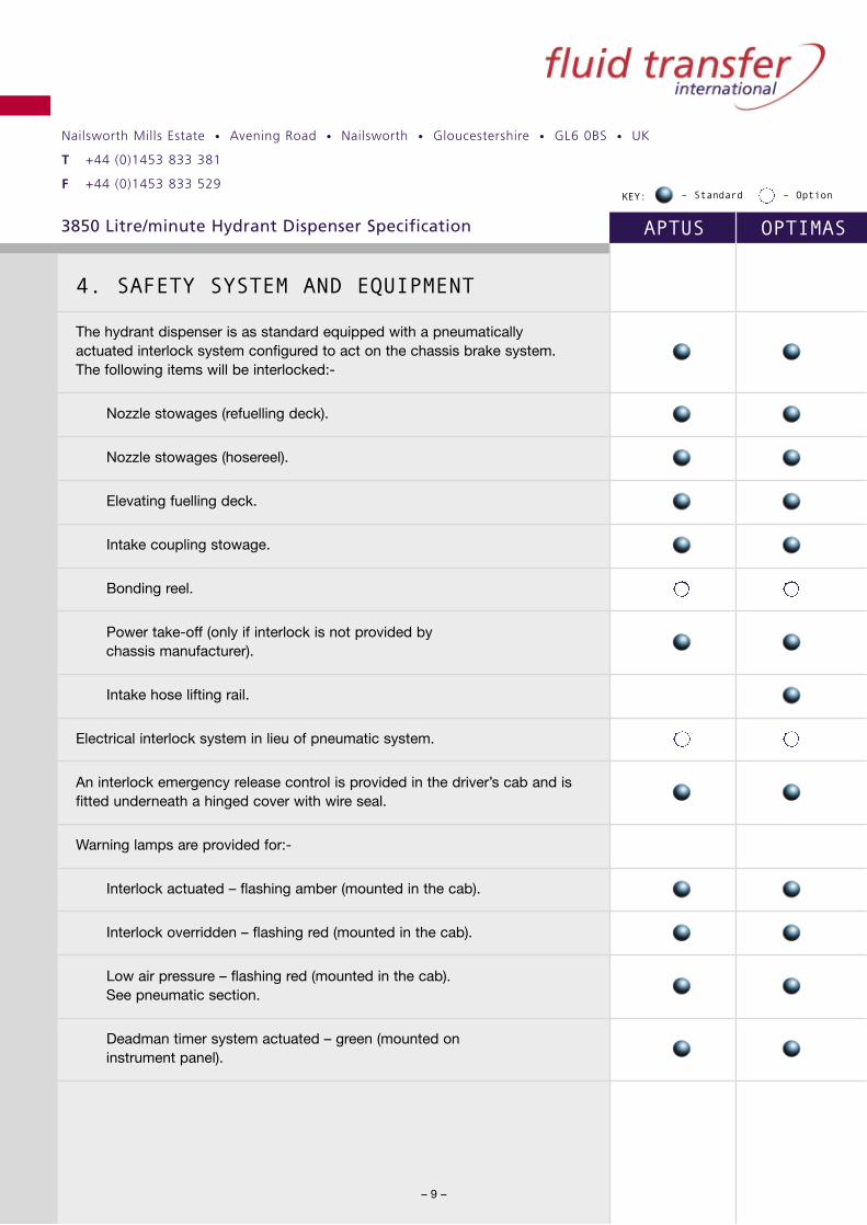
4. SAFETY SYSTEM AND EQUIPMENT
The hydrant dispenser is as standard equipped with a pneumaticallyactuated interlock system configured to act on the chassis brake system.The following items will be interlocked:-
Nozzle stowages (refuelling deck).
Nozzle stowages (hosereel).
Elevating fuelling deck.
Intake coupling stowage.
Bonding reel.
Power take-off (only if interlock is not provided by chassis manufacturer).
Intake hose lifting rail.
Electrical interlock system in lieu of pneumatic system.
An interlock emergency release control is provided in the driver’s cab and isfitted underneath a hinged cover with wire seal.
Warning lamps are provided for:-
Interlock actuated – flashing amber (mounted in the cab).
Interlock overridden – flashing red (mounted in the cab).
Low air pressure – flashing red (mounted in the cab).See pneumatic section.
Deadman timer system actuated – green (mounted on instrument panel).

Nailsworth Mills Estate • Avening Road • Nailsworth • Gloucestershire • GL6 0BS • UK
T +44 (0)1453 833 381
F +44 (0)1453 833 529
3850 Litre/minute Hydrant Dispenser Specification APTUS OPTIMAS
– 10 –
KEY: – Standard – Option
Audible alarms are provided for:-
Elevating fuelling deck descending.
Vehicle reversing.
Fitment of a brake interlock monitoring system. Consists of a display unitlocated in the driver’s cab, which indicates the status of each individualinterlocked item. If the brake interlock system is activated the display unitidentified which interlocked item or items is incorrectly stowed.

Nailsworth Mills Estate • Avening Road • Nailsworth • Gloucestershire • GL6 0BS • UK
T +44 (0)1453 833 381
F +44 (0)1453 833 529
3850 Litre/minute Hydrant Dispenser Specification APTUS OPTIMAS
– 11 –
KEY: – Standard – Option
5. ILLUMINATION
Illumination is by a fibre optical system and provides lighting for:-
Meter head.
Control panel.
Elevating fuelling deck access stairway.
A swivelling floodlamp is provided on the deck for illuminating the aircraft panel.
Switches for the above are provided in the cab and is enabled by thechassis side light system.
Nailsworth Mills Estate • Avening Road • Nailsworth • Gloucestershire • GL6 0BS • UK
T +44 (0)1453 833 381
F +44 (0)1453 833 529
3850 Litre/minute Hydrant Dispenser Specification APTUS OPTIMAS
– 12 –
KEY: – Standard – Option
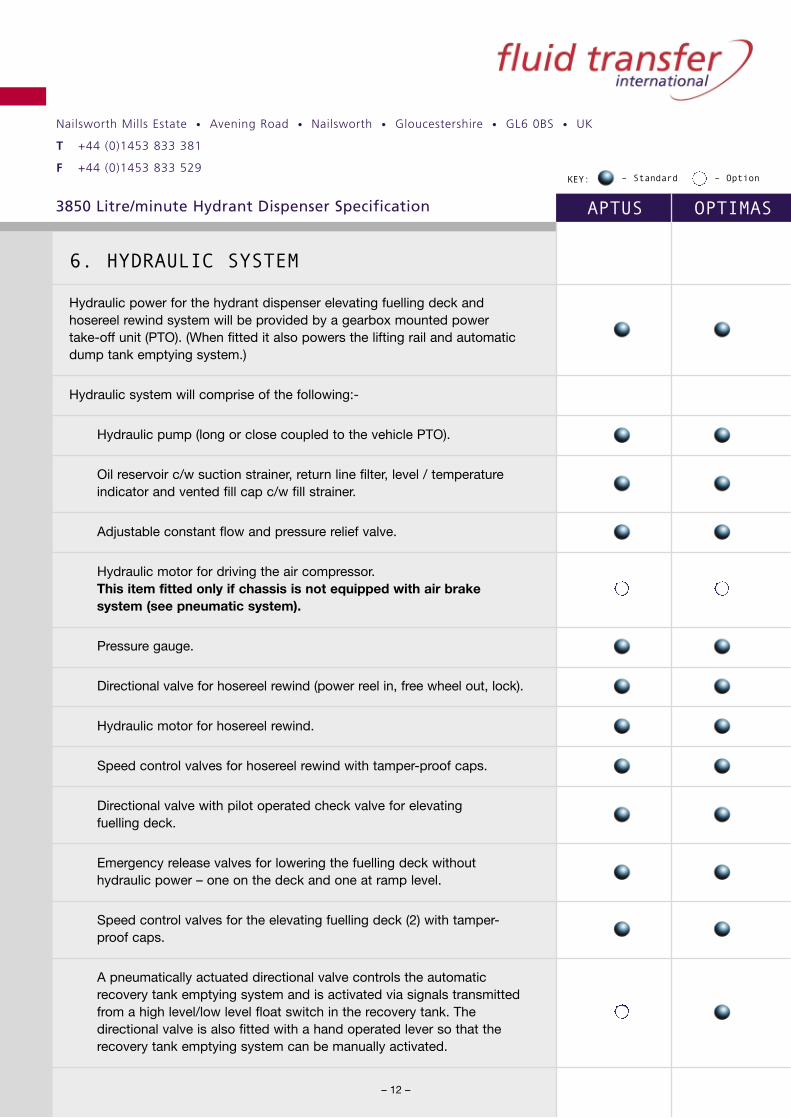
6. HYDRAULIC SYSTEM
Hydraulic power for the hydrant dispenser elevating fuelling deck andhosereel rewind system will be provided by a gearbox mounted power take-off unit (PTO). (When fitted it also powers the lifting rail and automaticdump tank emptying system.)
Hydraulic system will comprise of the following:-
Hydraulic pump (long or close coupled to the vehicle PTO).
Oil reservoir c/w suction strainer, return line filter, level / temperatureindicator and vented fill cap c/w fill strainer.
Adjustable constant flow and pressure relief valve.
Hydraulic motor for driving the air compressor. This item fitted only if chassis is not equipped with air brakesystem (see pneumatic system).
Pressure gauge.
Directional valve for hosereel rewind (power reel in, free wheel out, lock).
Hydraulic motor for hosereel rewind.
Speed control valves for hosereel rewind with tamper-proof caps.
Directional valve with pilot operated check valve for elevating fuelling deck.
Emergency release valves for lowering the fuelling deck withouthydraulic power – one on the deck and one at ramp level.
Speed control valves for the elevating fuelling deck (2) with tamper-proof caps.
A pneumatically actuated directional valve controls the automaticrecovery tank emptying system and is activated via signals transmittedfrom a high level/low level float switch in the recovery tank. Thedirectional valve is also fitted with a hand operated lever so that therecovery tank emptying system can be manually activated.

Nailsworth Mills Estate • Avening Road • Nailsworth • Gloucestershire • GL6 0BS • UK
T +44 (0)1453 833 381
F +44 (0)1453 833 529
3850 Litre/minute Hydrant Dispenser Specification APTUS OPTIMAS
– 13 –
KEY: – Standard – Option
7. PNEUMATIC SYSTEM
Compressed air for the hydrant dispenser pneumatic systems will be takenfrom the chassis air system at a safe designated point.*
Pneumatic system will comprise of the following:-
Pressure protection valve (if not already fitted).
Air reservoir with automatic drain valve, pressure protection valve andpressure gauge.
Air service unit.
Adjustable, lockable air pressure regulator (in-line pressure controladjustment) with pressure gauge.
Solenoid operated valve for deadman actuation.
Various spool valve (roller operated, pilot operated and lever operated),shuttle valves and pressure switches for actuation of the deadman,brake interlock and warning lamp systems.
* On hydrant dispenser utilising chassis not equipped with airbrake systems the air supply will be provided via a hydraulicallydriven, air compressor and unloader valve. The compressorassembly will be mounted to the hydrant dispenser superstructureand will operate only when the vehicle power take-off is engaged.A warning light indicating low air pressure when the power take-offis not engaged will be mounted in the vehicle cab.

Nailsworth Mills Estate • Avening Road • Nailsworth • Gloucestershire • GL6 0BS • UK
T +44 (0)1453 833 381
F +44 (0)1453 833 529
3850 Litre/minute Hydrant Dispenser Specification APTUS OPTIMAS
– 14 –
KEY: – Standard – Option
8. ELECTRICAL SYSTEM
Power for the hydrant dispenser electrical systems will be provided by theexisting chassis electrical system. Superstructure electrical components willbe positioned and mounted in accordance with accepted standards andpractices applicable to the nature of the vehicle.
Electrical system will comprise of the following:-
Deadman unit.
Deadman handswitch and cable.
Various warning lamps, audible alarms, pressure switches etc.
A flashing amber beacon is provided on the cab roof.
Operating lamps and floodlamp.
Fuse box with each circuit individually fused.
All wiring is routed in vapour and water-proof flexible conduit withsealed junction boxes and with an insulated return wiring system.
For electrical modifications to the chassis – see chassis section.
Nailsworth Mills Estate • Avening Road • Nailsworth • Gloucestershire • GL6 0BS • UK
T +44 (0)1453 833 381
F +44 (0)1453 833 529
3850 Litre/minute Hydrant Dispenser Specification APTUS OPTIMAS
– 15 –
KEY: – Standard – Option
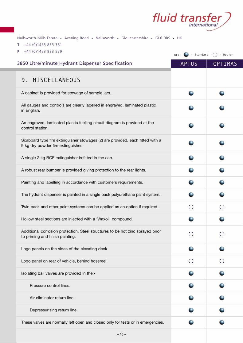
9. MISCELLANEOUS
A cabinet is provided for stowage of sample jars.
All gauges and controls are clearly labelled in engraved, laminated plastic in English.
An engraved, laminated plastic fuelling circuit diagram is provided at thecontrol station.
Scabbard type fire extinguisher stowages (2) are provided, each fitted with a9 kg dry powder fire extinguisher.
A single 2 kg BCF extinguisher is fitted in the cab.
A robust rear bumper is provided giving protection to the rear lights.
Painting and labelling in accordance with customers requirements.
The hydrant dispenser is painted in a single pack polyurethane paint system.
Twin pack and other paint systems can be applied as an option if required.
Hollow steel sections are injected with a ‘Waxoil’ compound.
Additional corrosion protection. Steel structures to be hot zinc sprayed priorto priming and finish painting.
Logo panels on the sides of the elevating deck.
Logo panel on rear of vehicle, behind hosereel.
Isolating ball valves are provided in the:-
Pressure control lines.
Air eliminator return line.
Depressurising return line.
These valves are normally left open and closed only for tests or in emergencies.

Nailsworth Mills Estate • Avening Road • Nailsworth • Gloucestershire • GL6 0BS • UK
T +44 (0)1453 833 381
F +44 (0)1453 833 529
3850 Litre/minute Hydrant Dispenser Specification APTUS OPTIMAS
– 16 –
KEY: – Standard – Option
Blanked sockets are provided for the retro fitment of self sealing couplingsfor the purpose of in-situ hose pressure testing and for retro fitment ofmillipore sample couplings.
Bonding lugs are provided adjacent to the recovery tank drain valve anddrain / sample valve panel.
The deck hose nozzles are stowed on the guard rails in an interlockstowage c/w hinged rain cover.
The reel hose nozzles are stowed in interlocked ‘bucket’ type stowages.
Pneumatic lines are constructed in UV resistant, colour coded andnumbered nylon tubing. All pneumatic valve exhaust ports are fitted withmufflers which help prevent ingress of moisture.
Electrical continuity is maintained throughout all components in the fuelling system.
Nailsworth Mills Estate • Avening Road • Nailsworth • Gloucestershire • GL6 0BS • UK
T +44 (0)1453 833 381
F +44 (0)1453 833 529
3850 Litre/minute Hydrant Dispenser Specification APTUS OPTIMAS
– 17 –
KEY: – Standard – Option
1O. TESTING
The superstructure will be flow and pressure tested in FTi Test House usingJet A1 fuel to verify pre-qualification performance.
Tests include:-
Static pressure test 15.3 bar (225 p.s.i.).
Maximum flow rate.
Venturi correlation.
Primary pressure control systems.
Secondary (in line) pressure control system.
Deadman opening / closing times.
Deadman fuel volume overshoot.
Functioning of all controls, warning devices, etc.
Electrical continuity test.
The vehicle is designed to permit ‘in-situ’ hose pressure testing of the intakeand delivery hoses to 20 bar (300 p.s.i.) without the need to remove hosesfrom the vehicle.

Nailsworth Mills Estate • Avening Road • Nailsworth • Gloucestershire • GL6 0BS • UK
T +44 (0)1453 833 381
F +44 (0)1453 833 529
3850 Litre/minute Hydrant Dispenser Specification APTUS OPTIMAS
– 18 –
KEY: – Standard – Option
11. PERFORMANCE
Based on a hydrant pressure of 8.6 bar (125 p.s.i.) at the pit coupler and a test rig back pressure of 2.1 bar (30 p.s.i.).
Deck hoses (Ø63mm) – up to 3850 LPM (850 IGPM).
Reel hose (Ø50mm) – up to 1000 LPM (220 IGPM).
Reel hose (Ø63mm) – up to 1370 LPM (300 IGPM).
Primary pressure control system (hose end pressure control) limitspressure into the aircraft manifold to 3.4 bar (50 p.s.i.) under flowconditions and normal shutdown conditions and to 8.2 bar (120 p.s.i.)under rapid shutdown (surge conditions).
The secondary (in line) pressure control system limits pressure into theaircraft manifold to 3.74 bar (55 p.s.i.) adjustable under flow conditions.
The deadman system will shut down flow completely within 5 secondsof releasing the deadman switch. Flow will be restored to 90% within10 seconds of re-gripping the switch. Valve opening and closing timesare pre-set and not adjustable.
Nailsworth Mills Estate • Avening Road • Nailsworth • Gloucestershire • GL6 0BS • UK
T +44 (0)1453 833 381
F +44 (0)1453 833 529
3850 Litre/minute Hydrant Dispenser Specification APTUS OPTIMAS
– 19 –
KEY: – Standard – Option
12. PUBLICATIONS
Each vehicle will be supplied with:-
Operating, maintenance and parts manuals for the hydrant dispenserrefuelling module in English
Recommended spare parts list.
Relevant Test Certificates and Certificates of Conformity will beprovided in accordance with Fluid Transfer International QualityAssurance Certification to ISO 9001:2000.

Nailsworth Mills Estate • Avening Road • Nailsworth • Gloucestershire • GL6 0BS • UK
T +44 (0)1453 833 381
F +44 (0)1453 833 529
3850 Litre/minute Hydrant Dispenser Specification APTUS OPTIMAS
KEY: – Standard – Option
13. FUELLING CIRCUIT COMPONENT INDEX
(Refer to attached circuit diagram)
1. Intake coupling with integral secondary pressure control anddeadman valve c/w retractable carriage.
2. Intake hose – aviation type conforming to BS3158 Type C, HDØ100mm bore x 10m long with reusable end fittings.
3. Intake swivel – FTi Ø100mm.
4. Intake valve – FTi Ø100mm stainless steel ball valve.
5. Filter monitor, horizontal type in stainless steel, meeting therequirements of I.P. specification at a maximum flow rate of 4087LPM (900 IGPM) when fitted with 34/36 off monitor elements.Designed and constructed to A.S.M.E. VIII. Cover fitted with swingbolts and ‘O’ ring seal.
5a. Monitor interlock plate to ensure correct number of elements fitted.
6. 28 litre capacity surge suppressor.
7. Meter, rotary valve, positive displacement meter fitted with amechanical register with resettable register, non-resettabletotaliser, mechanical rate of flow indicator.
8. Sampling point 3/8" BSPPF socket c/w blanking plug.
9. Deck hose flow control valve – FTi Ø100mm stainless steel ball valve.
10. Venturi – FTi Ø100mm fully compensating type.
11. Deck hose swivel – FTi Ø100mm.
– 20 –
Nailsworth Mills Estate • Avening Road • Nailsworth • Gloucestershire • GL6 0BS • UK
T +44 (0)1453 833 381
F +44 (0)1453 833 529
3850 Litre/minute Hydrant Dispenser Specification APTUS OPTIMAS
– 21 –
KEY: – Standard – Option
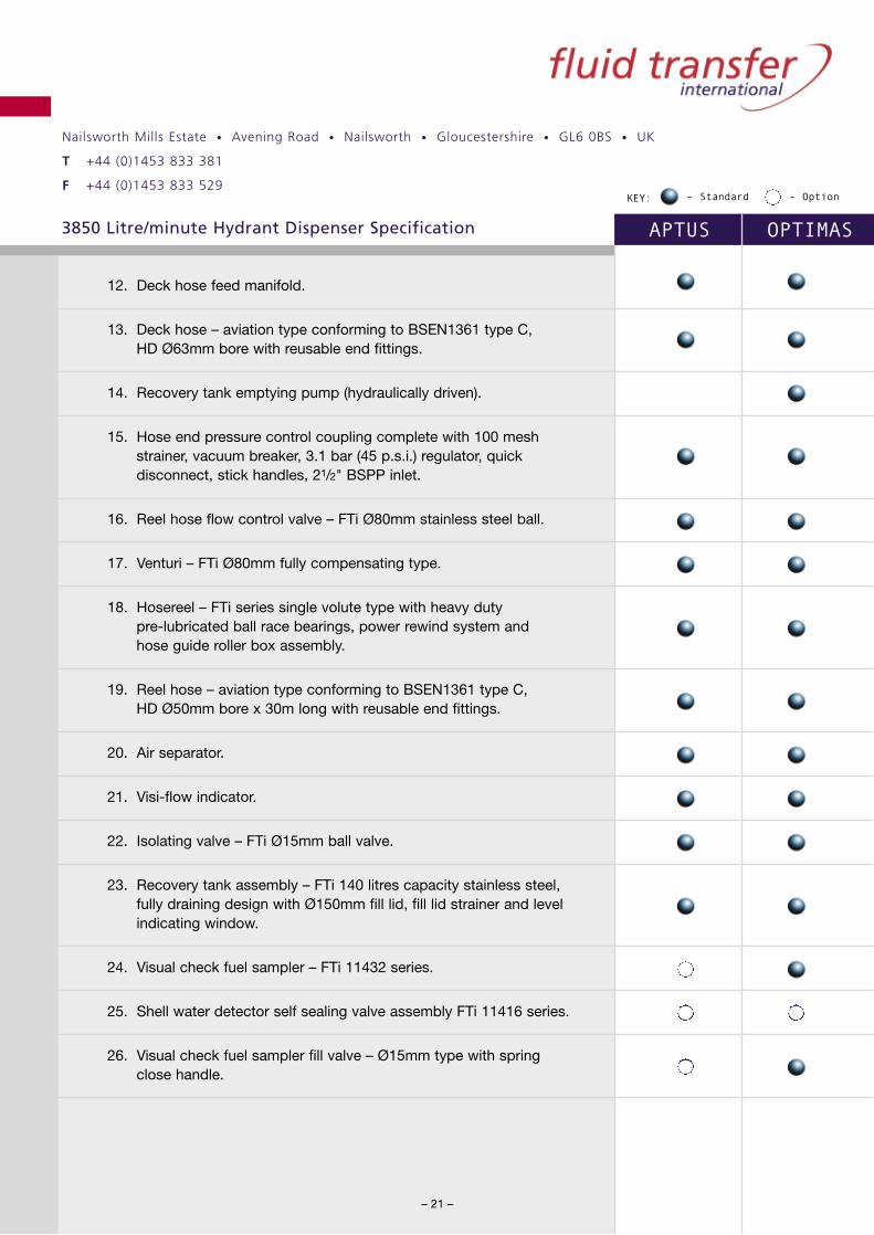
12. Deck hose feed manifold.
13. Deck hose – aviation type conforming to BSEN1361 type C, HD Ø63mm bore with reusable end fittings.
14. Recovery tank emptying pump (hydraulically driven).
15. Hose end pressure control coupling complete with 100 meshstrainer, vacuum breaker, 3.1 bar (45 p.s.i.) regulator, quickdisconnect, stick handles, 21/2" BSPP inlet.
16. Reel hose flow control valve – FTi Ø80mm stainless steel ball.
17. Venturi – FTi Ø80mm fully compensating type.
18. Hosereel – FTi series single volute type with heavy duty pre-lubricated ball race bearings, power rewind system and hose guide roller box assembly.
19. Reel hose – aviation type conforming to BSEN1361 type C, HD Ø50mm bore x 30m long with reusable end fittings.
20. Air separator.
21. Visi-flow indicator.
22. Isolating valve – FTi Ø15mm ball valve.
23. Recovery tank assembly – FTi 140 litres capacity stainless steel,fully draining design with Ø150mm fill lid, fill lid strainer and levelindicating window.
24. Visual check fuel sampler – FTi 11432 series.
25. Shell water detector self sealing valve assembly FTi 11416 series.
26. Visual check fuel sampler fill valve – Ø15mm type with spring close handle.

Nailsworth Mills Estate • Avening Road • Nailsworth • Gloucestershire • GL6 0BS • UK
T +44 (0)1453 833 381
F +44 (0)1453 833 529
3850 Litre/minute Hydrant Dispenser Specification APTUS OPTIMAS
– 22 –
KEY: – Standard – Option
27. Pressure maintaining valve (set at 1 bar) – FTi.
28. Manual depressurising valve – Ø15mm type with spring close handle.
29. Thermal pressure relief valve – FTi pneumatically actuated type.
30. Isolating valve FTi Ø15mm ball valve.
31. Non-return valve.
32. Drain / sample valve – FTi Ø19mm ball valve.
33. Drip cap – Ø19mm type.
34. Safety thermal pressure relief valve adjusted to relieve at 15.3 bar(225 p.s.i.) – FTi.
35. One way flow restrictor – FTi Ø15mm type DB4956.
36. Restrictor valve – FTi.
37. Isolating valve (closed only during ‘in-situ’ pressure testing of thehoses) – FTi Ø15mm ball valve.
38. Isolating valve – FTi Ø15mm ball valve.
39. Isolating valve (closed during in ‘in-situ’ hose pressure testing – FTi Ø15mm ball valve.
40. Non return valve (hose depressurising system) – FTi.
41. Filter differential pressure gauge – linear piston type 0-2 bar (0-30 p.s.i.).
42. Venturi sense pressure gauge – Ø100mm glycerine filled type 0-13 bar (0–200 p.s.i.).
43. Inlet pressure gauge – Ø100mm glycerine filled type 0-13 bar (0-200 p.s.i.).

Nailsworth Mills Estate • Avening Road • Nailsworth • Gloucestershire • GL6 0BS • UK
T +44 (0)1453 833 381
F +44 (0)1453 833 529
3850 Litre/minute Hydrant Dispenser Specification APTUS OPTIMAS
– 23 –
KEY: – Standard – Option
44. Test valve (differential pressure gauge)
45. Gauge isolating valve – FTi Ø6mm ball valve.
46. Gauge test point – self sealing coupling.
47. 3/8" BSPPF socket c/w blanking plug.
48. Control pressure signal hose – Ø10mm bore.
49. Air reference pressure hose – Ø6mm bore.
50. Deadman handswitch c/w coiled wanderlead and plug – FTi type DAA11115.
51. Deadman timer unit and current limiting relay – FTi DBA10826 integrated series.
52. Deadman actuating valve (solenoid operated).
53. Deadman override valve.
54. Deadman timer prompt lamp.
55. Air pressure regulator – Self relieving type.
56. Air reference pressure gauge – 100mm glycerine filled type 0-13 bar (0-200 psi).
Nailsworth Mills Estate • Avening Road • Nailsworth • Gloucestershire • GL6 0BS • UK
T +44 (0)1453 833 381
F +44 (0)1453 833 529
3850 Litre/minute Hydrant Dispenser Specification APTUS OPTIMAS
– 24 –
KEY: – Standard – Option
14. CHASSIS AND CHASSIS MODIFICATIONS
The hydrant dispenser superstructure will be configured to be mounted tothe following typical chassis:-
Mercedes Benz Vario – 612D/3700.– 614D/3700
Isuzu NPR65L-RPV or Mitsubishi equivalent.
DAF FA45-130.
The chassis will, where applicable, have the following basic specification:-
5500 / 6500 kgs GVW.
Diesel engine.
Manual gearbox.
12 / 24 volt electrical system.
4 x 2 wheel configuration.
Gearbox mounted power take-off.
Approximate chassis wheelbases will be:-
Fixed cab chassis @ 3700mm.
Tilt cab chassis @ 3365mm.
Chassis specifications will be adjusted where necessary to meet specificcustomer requirements and to suit local regulations.
Alternative chassis can be offered if requested (further details on request.

Nailsworth Mills Estate • Avening Road • Nailsworth • Gloucestershire • GL6 0BS • UK
T +44 (0)1453 833 381
F +44 (0)1453 833 529
3850 Litre/minute Hydrant Dispenser Specification APTUS OPTIMAS
– 25 –
KEY: – Standard – Option
The chassis will, where applicable, be modified to conform to the followingspecification:-
a) Modification of chassis exhaust system to discharge forward of thefront axle, discharging to the opposite side from the control station.On chassis where routing of the exhaust forward of the front axle isnot possible, the exhaust will be mounted transversely across thechassis as close to the rear of the front axle as possible withexposed parts shielded as required. Internal silencer/spark arrestorcan be installed, as an option, if required.
b) All electrical wiring behind the driver’s cab will be routed in a fireretardant and flexible protective casing.
c) Electrical components behind the driver’s cab will be wired inaccordance with current ‘CEN’ Requirements (unless otherwisespecified by the customer).
d) Single or double pole battery isolating switch (subject to wiring specification).
e) Firescreen behind the driver’s cab and enclosed batteries vehicleswith tilt type cabs.
All superstructure mounting methods and system interfaces will, where applicable, be in accordance with chassis manufacturer’s bodybuilder recommendations.