1 era of customization and specialization era of customization and specialization for...
Post on 18-Dec-2015
234 views
TRANSCRIPT

1
Era of Customization and Specialization Era of Customization and Specialization for Energy-Efficient Computing
Jason CongDirector, Center for Domain-Specific Computing
www.cdsc.ucla.edu
Chancellor’s Professor, UCLA Computer Science [email protected]

2
Is Semiconductor a Sunset Industry ?Is Semiconductor a Sunset Industry ?
Source : Shekhar Borkar, Intel
• Frequency scaling has stopped a decade ago due to power barrier• CMOS device scaling is coming to the end soon, with no sure replacement in sight

3
Current Solution to Power BarrierCurrent Solution to Power Barrier
Parallelization
• 10’s to 100’s cores in a processor
• 1000’s to 10,000’s servers in a data center

4
Cost and Energy are Still a Big Issue …Cost and Energy are Still a Big Issue …
Cost of computing
•HW acquisition
•Energy bill
•Heat removal
•Space
•…
5
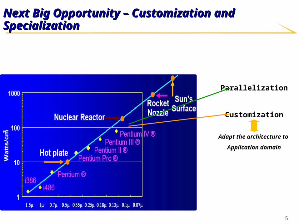
Next Big Opportunity – Customization and SpecializationNext Big Opportunity – Customization and Specialization
Parallelization
Customization
Adapt the architecture to
Application domain

6
[1] Amphion CS5230 on Virtex2 + Xilinx Virtex2 Power Estimator
[2] Dag Arne Osvik: 544 cycles AES – ECB on StrongArm SA-1110
[3] Helger Lipmaa PIII assembly handcoded + Intel Pentium III (1.13 GHz) Datasheet
[4] gcc, 1 mW/MHz @ 120 Mhz Sparc – assumes 0.25 u CMOS
[5] Java on KVM (Sun J2ME, non-JIT) on 1 mW/MHz @ 120 MHz Sparc – assumes 0.25 u CMOS
Justification 1 – Potential of CustomizationJustification 1 – Potential of Customization
648 Mbits/secAsm
Pentium III [3] 41.4 W 0.015 (1/800)
Java [5] Emb. Sparc450 bits/sec 120 mW 0.0000037 (1/3,000,000)
C Emb. Sparc [4]133 Kbits/sec 0.0011 (1/10,000)
350 mW
Power
1.32 Gbit/secFPGA [1]
11 (1/1)3.84 Gbits/sec0.18m CMOS
Figure of Merit(Gb/s/W)
ThroughputAES 128bit key128bit data
490 mW 2.7 (1/4)
120 mW
ASM StrongARM [2]240 mW 0.13
(1/85)31 Mbit/sec
Source: P. Schaumont, and I. Verbauwhede, "Domain specific codesign for embedded security," IEEE Computer 36(4), 2003.

7
Justification 2 -- Justification 2 -- Advance of Civilization Advance of Civilization For human brain, Moore’s Law scaling has long stoppedFor human brain, Moore’s Law scaling has long stopped
The number neurons and their firing speed did not change significantly
Remarkable advancement of civilization via specializationRemarkable advancement of civilization via specialization More advanced societies have higher degree of specializationMore advanced societies have higher degree of specialization

8
Our GoalsOur Goals A general, customizable platform
Can be customized to a wide-range of applications
• May focus on one or several given domains
Can be massively produced with cost efficiency
Can be programmed efficiently with novel compilation and runtime systems
Metric of success Metric of success
A “supercomputer-in-a-box” with 100X performance/power improvement via A “supercomputer-in-a-box” with 100X performance/power improvement via customization for the intended domain(s)customization for the intended domain(s)

9
Example of Customizable Platforms: FPGAsExample of Customizable Platforms: FPGAs Configurable logic Configurable logic
blocksblocks Island-style configurable Island-style configurable
mesh routingmesh routing Dedicated componentsDedicated components
Specialization allows Specialization allows optimizationoptimization
Memory/MultiplierMemory/Multiplier I/O, ProcessorI/O, Processor Anything that the FPGA Anything that the FPGA
architect wants to put in!architect wants to put in!
Source: I. Kuon, R. Tessier, J. Rose. FPGA Architecture: Survey and Challenges. 2008.

10
More Opportunities for Customization to be ExploredMore Opportunities for Customization to be Explored
Key questions: Optimal trade-off between efficiency & customizabilityWhich options to fix at CHP creation? Which to be set by CHP mapper?
Custom instructions & acceleratorsShared vs. private acceleratorsChoice of acceleratorsCustom instruction selectionAmount of programmable fabric …
Custom instructions & acceleratorsShared vs. private acceleratorsChoice of acceleratorsCustom instruction selectionAmount of programmable fabric …
Core parametersFrequency & voltageDatapath bit widthInstruction window sizeIssue widthCache size & configurationRegister file organization# of thread contexts…
Core parametersFrequency & voltageDatapath bit widthInstruction window sizeIssue widthCache size & configurationRegister file organization# of thread contexts…
NoC parametersInterconnect topology # of virtual channelsRouting policyLink bandwidthRouter pipeline depthNumber of RF-I enabled routersRF-I channel and bandwidth allocation…
NoC parametersInterconnect topology # of virtual channelsRouting policyLink bandwidthRouter pipeline depthNumber of RF-I enabled routersRF-I channel and bandwidth allocation…
Our Proposal: Customizable Heterogeneous Platform (CHP)
$$ $$ $$ $$
FixedCore
FixedCore
FixedCore
FixedCore
FixedCore
FixedCore
FixedCore
FixedCore
CustomCore
CustomCore
CustomCore
CustomCore
CustomCore
CustomCore
CustomCore
CustomCore
ProgFabricProg
FabricProg
FabricProg
Fabric acceleratoraccelerator acceleratoraccelerator
Reconfigurable RF-I busReconfigurable optical busTransceiver/receiverOptical interface
Cache parametersCache size & configurationCache vs SPM…
Cache parametersCache size & configurationCache vs SPM…

11
Examples of CustomizationExamples of Customization
Customization of processor coresCustomization of processor cores
Customization of on-chip memoryCustomization of on-chip memory
Customization of on-chip interconnectsCustomization of on-chip interconnects
12
Example 1 – Customization of CoresExample 1 – Customization of Cores Large cores or small cores?Large cores or small cores?
How many each type?How many each type?

13
Core spilling – [Cong et al Trans. on Parallel and Distributed Systems 2007] CMP systems focus on
improving overall throughput Sequential or legacy
applications might not see benefits
Key idea – allow execution to be spilt from one core to next at run-time Simulate increase in
register file, instruction queue, ROB and LSQ size
Allocate cores intelligently to spilling core

14
Core spilling – [Cong et al Trans. on Parallel and Distributed Systems 2007] Results
Core spilling achieves more than 50% of the performance of ‘ideal’ 32-issue core by using 4-issue cores for single applications
39% improvement for multiple application workload Up to 40% reduction in latency for changing workloads

15
Example 2: Customization of On-Chip MemoryExample 2: Customization of On-Chip Memory HW controlled cache or SW controlled cache (SPM)?HW controlled cache or SW controlled cache (SPM)?
How much to allocate for each type?How much to allocate for each type?

16
Customizable Hybrid L1 Cache [ISLPED’2011] Cache in conjunction with Scratchpad Memory (SPM) in L1
• Cache: Hardware-controlled Transparent to software: a fast local copy of the global memory address space
• SPM: Software-controlled Not transparent to software: a separate address space from the global address space
Customizable• Flexibly size the cache and SPM based on the application requirements
Cache: dynamic/random access SPM: regular data access pattern
Tag Array DecoderUnit
Column Circuitry
Data Array
(a) Cache memory organization
Column Circuitry
Data ArrayDecoderUnit
(b) SPM organization
Cache SPM
accesstime
hit : 1 cyclemiss : L cycles
1 cycle
energy 4.57 nJ 1.53 nJ
(c) Comparison (2KB)16

17
How to Customize?How to Customize?Way-wise reconfigurable cache
Configure several ways of cache as SPM
Column cache [Chiou et.al. DAC’00]
64B
Cache set
64B
Cache set
Hot set
Hot set
Cold set
Cache setsCache sets00
Run Run timetime
00
00
64B
Cache set
Run Run timetime
Run Run timetime
Cache setsCache sets
Cache setsCache sets
Block-wise reconfigurable
cache Virtual local store [Cook
et.al. UCB TR’09]
Unified mapping of SPM blocks onto cache blocks
Adaptive hybrid cache (AH-
Cache) Dynamically remap SPM
blocks from high-demand cache sets to low-demand cache sets.
rician-denoiserician-denoise
17
cache SPM

18
Challenge 1 : Fast SPM LocationChallenge 1 : Fast SPM Location
SPM Lookup and access in AH-Cache SPM Mapping Lookup Table (SMLT)
• Store SPM mapping information Additional SMLT lookup stage
• May increase the critical path
Zero-timing overhead SPM location• Hide SMLT lookup in EX pipeline with
address generation
The memory reference instructions to the SPM should be:• Base address: the base address of the SPM
array• Offset: the offset related to the SPM base
address
Set indexWay index
ID/EX
EX/
MEM
Comparator
ALUBase address
SPM base address
offset
Valid bit
Is_SPM_access
SMLT
Decoder
Output driver
Comp-arator
Comp-arator
Output driver
Word lines Word lines
Tag array Data arraySet index
Is_SPM_access
TLB
Tag
Block address
Way index
Way index decoder
Way index Set index
Set and way index
18

19
Challenge 2 : Efficient Adaptive MappingChallenge 2 : Efficient Adaptive Mapping Circular bouncing effect
Cache set A holds an SPM block and becomes hot
Cache set A sends the SPM block to a cold set B• A enable the cache way as a regular cache block
• B will evict one of its cache blocks to accommodate the SPM block
Cache set B becomes hot and sends the SPM block back to A
A->B->A->B….
Key idea to avoid circular bouncing effect Floating-block-holder (FBH) queue: record the cache sets currently holding the floating
cache blocks A hot set will not give up its floating blocks once re-inserted in the FBH queue in an
adaptation interval
Less than 6% per-cache-access energy overhead
Only 4.4 SPM remapping on average per 106-cycle interval for our benchmarks
19
20
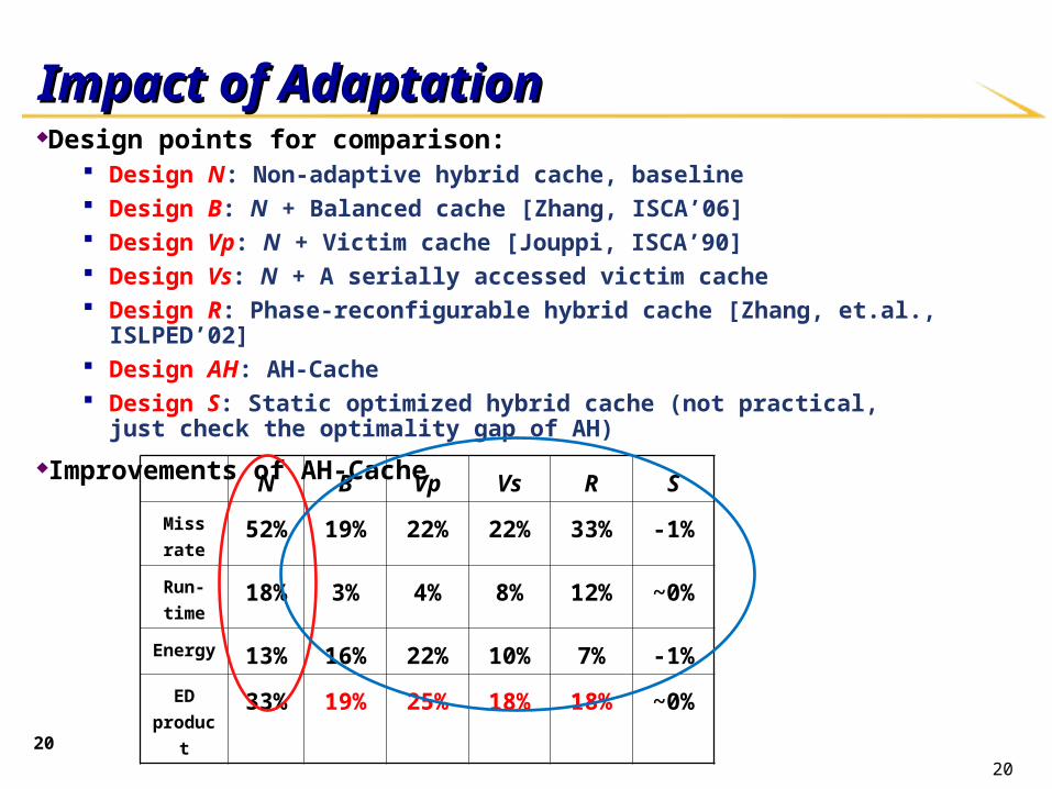
Impact of AdaptationImpact of AdaptationDesign points for comparison:
Design N: Non-adaptive hybrid cache, baseline Design B: N + Balanced cache [Zhang, ISCA’06] Design Vp: N + Victim cache [Jouppi, ISCA’90] Design Vs: N + A serially accessed victim cache Design R: Phase-reconfigurable hybrid cache [Zhang, et.al., ISLPED’02] Design AH: AH-Cache Design S: Static optimized hybrid cache (not practical, just check the optimality gap of AH)
Improvements of AH-Cache
N B Vp Vs R S
Miss rate 52% 19% 22% 22% 33% -1%
Run-time 18% 3% 4% 8% 12% ~0%
Energy 13% 16% 22% 10% 7% -1%
ED
product33% 19% 25% 18% 18% ~0%
20

21
Example 3: Customization of On-Chip InterconnectsExample 3: Customization of On-Chip Interconnects
How many wires to include for on-chip How many wires to include for on-chip
communication?communication?
Uniform distribution and dedicated connections?Uniform distribution and dedicated connections?

2222
Our Answer : Use of Multiband RF-Interconnect for Customization
• In TX, each mixer up-converts individual baseband streams into specific frequency band (or channel)
• N different data streams (N=6 in exemplary figure above) may transmit simultaneously on the shared transmission medium to achieve higher aggregate data rates
• In RX, individual signals are down-converted by mixer, and recovered after low-pass filter
10GHz 20GHz 30GHz 40GHz 50GHz 60GHzf
Sig
nal S
pec
trum
60GHz
10GHz
Transmission Line
Output BufferMixer Mixer LPF
frequency
Sig
na
l Po
we
r Data1
frequency
Sig
na
l Po
we
r Data6
frequency
Sig
nal
Pow
er Data1
frequency
Sig
nal
Po
we
r Data6
10GHz
X 6 TX
X6 RX
60GHz

23
Terahertz VCO in 65nm CMOSTerahertz VCO in 65nm CMOS Demonstrated an ultra high Demonstrated an ultra high
frequency and low power oscillator frequency and low power oscillator
structure in CMOS by adding a structure in CMOS by adding a
negative resistance parallel tank, negative resistance parallel tank,
with the fundamental frequency at with the fundamental frequency at
217GHz and 16.8 mW DC power 217GHz and 16.8 mW DC power
consumption. consumption.
The measured 4The measured 4thth and 6 and 6thth harmonics harmonics
are about 870GHz and 1.3THz, are about 870GHz and 1.3THz,
respectively. respectively.
Measured signal spectrum with uncalibrated power
higher harmonics (4th and 6th harmonics) may be substantially underestimated due to excessive water
and oxygen absorption and setup losses at these frequencies.
“Generating Terahertz Signals in 65nm CMOS with Negative-Resistance Resonator Boosting and Selective Harmonic Suppression” Symposium on VLSI Technology and Circuits, June 2010

2424
Mesh Overlaid with RF-I [HPCA’08]
10x10 mesh of pipelined routers NoC runs at 2GHz XY routing
64 4GHz 3-wide processor cores Labeled aqua 8KB L1 Data Cache 8KB L1 Instruction Cache
32 L2 Cache Banks Labeled pink 256KB each Organized as shared NUCA cache
4 Main Memory Interfaces Labeled green
RF-I transmission line bundle Black thick line spanning mesh

2525
RF-I Logical Organization
• Logically:- RF-I behaves as set of N express channels- Each channel assigned to src, dest router pair (s,d)
• Reconfigured by:- remapping shortcuts to
match needs of different applications LOGICAL ALOGICAL B

2626
Power Savings [MICROPower Savings [MICRO’’08]08]
We can thin the baseline mesh links From 16B… …to 8B …to 4B
RF-I makes up the difference in performance while saving overall power! RF-I provides bandwidth where
most necessary Baseline RC wires supply the
rest
16 bytes8 bytes4 bytes
Requires high bw to communicate w/ B
A
B
2727
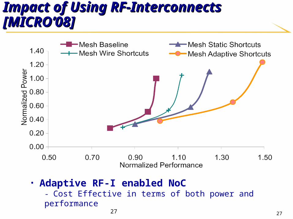
Impact of Using RF-Interconnects [MICROImpact of Using RF-Interconnects [MICRO’’08]08]
• Adaptive RF-I enabled NoC- Cost Effective in terms of both power and performance

28
Specialization is also ImportantSpecialization is also Important
Specialized accelerators used to be considered “wasteful”Specialized accelerators used to be considered “wasteful” A storyA story
Van Neumann architecture maximizes device reuseVan Neumann architecture maximizes device reuse Utilization wall Utilization wall
6.5% utilization for a 45 nm chip filled with 64bit operators, 6.5% utilization for a 45 nm chip filled with 64bit operators, assuming a power budget of 80 W [ASPLOS’2010]assuming a power budget of 80 W [ASPLOS’2010]

29
Our Proposal: Extensive Use of Accelerators Our Proposal: Extensive Use of Accelerators [SAW’2011] [SAW’2011]
Proposed solution: extensive use of Proposed solution: extensive use of accelerators (customized or implemented accelerators (customized or implemented using programmable fabric)using programmable fabric) Sea of acceleratorsSea of accelerators
Type of accelerators:Type of accelerators: Tightly vs. loosely coupledTightly vs. loosely coupled
BenefitsBenefits Better performanceBetter performance Higher power-efficiencyHigher power-efficiency It’s ok to be “wasteful”It’s ok to be “wasteful”
Critical needs:Critical needs: Efficient accelerator managementEfficient accelerator management
• SchedulingScheduling• SharingSharing
Ac
ce
lera
tor2
Ac
ce
lera
tor1
Core3
Core1
Core4
Core2
L1 L1
L1 L1
L2 L2
L2 L2
NoC
M B B C C B B M
B B B C C B B B
C C C C C C C C
A A A A A A A A
A A A GAM A A A A
C C C C C C C C
B B B C C B B B
M B B C C B B M
Router CoreC B L2 Banks
AAccelerator +
DMA MMemory Cotroller

30
Using Accelerators with OS ManagementUsing Accelerators with OS Management
Managing accelerator by OS is expensiveManaging accelerator by OS is expensive
In an accelerator rich CMP, management should be cheaper both in terms In an accelerator rich CMP, management should be cheaper both in terms of time and energyof time and energy
OperationLatency (# Cycles)
1 core 2 cores 4 cores 8 cores 16 cores
Invoke 214413 256401 266133 308434 316161
RD/WR 703 725 781 837 885
31
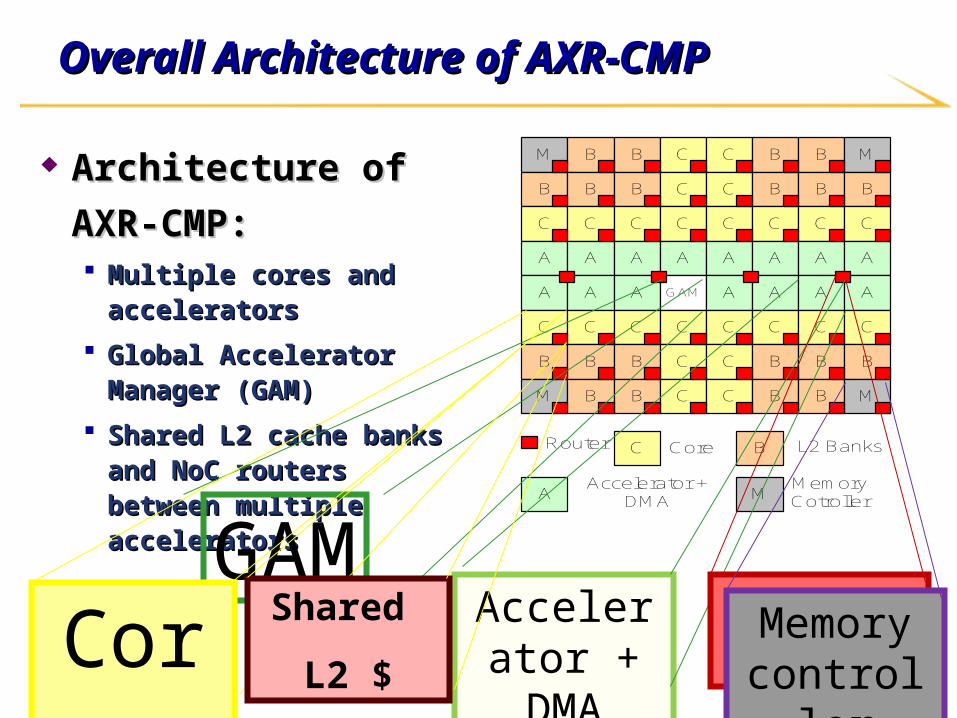
Overall Architecture of AXR-CMPOverall Architecture of AXR-CMP
Architecture of AXR-CMP:Architecture of AXR-CMP: Multiple cores and acceleratorsMultiple cores and accelerators
Global Accelerator Manager Global Accelerator Manager (GAM)(GAM)
Shared L2 cache banks and NoC Shared L2 cache banks and NoC routers between multiple routers between multiple accelerators accelerators
M B B C C B B M
B B B C C B B B
C C C C C C C C
A A A A A A A A
A A A GAM A A A A
C C C C C C C C
B B B C C B B B
M B B C C B B M
Router CoreC B L2 Banks
AAccelerator +
DMA MMemory Cotroller
GAMAccelerator
+ DMAShared RouterCore
Shared
L2 $Memory controller

32
Overall Communication Scheme in AXR-CMPOverall Communication Scheme in AXR-CMP
1. The core requests and the GAM responds with a list (lcacc-req).
2. The core reserves (lcacc-rsv) and waits.
3. The core shares a task description to accelerator in memory and starts it (lcacc-cmd), the accelerator reads the task description, and begins working.
4. When the accelerator finishes its current task it notifies the core. The core then sends a message to the GAM freeing the accelerator (lcacc-free).
New ISA
lcacc-req t
lcacc-rsrv t, e
lcacc-cmd id, f, addr
lcacc-free id

33
Light-weight Interrupt SupportLight-weight Interrupt Support
To reduce OS interrupt serviceTo reduce OS interrupt service No need to save contextNo need to save context
Two main components added:Two main components added: A table to store ISR infoA table to store ISR info
An interrupt controller to queue and prioritize An interrupt controller to queue and prioritize incoming interrupt packetsincoming interrupt packets
Each thread registers: Each thread registers: Address of the ISR and its argumentsAddress of the ISR and its arguments
lw-int sourcelw-int source
Sources of lw-int:Sources of lw-int: GAM responsesGAM responses
• Accelerator readyAccelerator ready• Wait time for acceleratorWait time for accelerator
Accelerator TLB miss Accelerator TLB miss
Accelerator task buffer emptyAccelerator task buffer empty
Limitations:Limitations: Only can be used when running the same Only can be used when running the same
thread which LW interrupt belongs tothread which LW interrupt belongs to
OS-handled interrupt otherwiseOS-handled interrupt otherwise
OperationLatency (# Cycles)
1 core 2 cores 4 cores 8 cores 16 cores
Interrupt 16383 20361 24022 26572 28574

34
Accelerator Chaining and CompositionAccelerator Chaining and Composition
ChainingChaining To have an efficient To have an efficient
accelerator to accelerator to accelerator accelerator communicationcommunication
CompositionComposition To create the virtual To create the virtual
feeling of having feeling of having larger accelerators larger accelerators for the applicationsfor the applications 10x10
MatrixMultiplier
TransformedScratchpad
5x5Matrix
Mul/Add
Scratchpad
5x5Matrix
Mul/Add
Scratchpad
5x5Matrix
Mul/Add
Scratchpad
5x5Matrix
Mul/Add

35
Hardware Overhead AnalysisHardware Overhead Analysis
AutoPilot to synthesize Global Accelerator Manager (GAM) AutoPilot to synthesize Global Accelerator Manager (GAM)
module and DMA-Cmodule and DMA-C Area is less than 0.01% of the chip (1cm X 1cm) using 65 nm Area is less than 0.01% of the chip (1cm X 1cm) using 65 nm
technology.technology.
Module Clock speed Area (u2m) Power (mW)
GAM 2 ns 12270 2.64DMA-C 2 ns 10071 0.09
AutoPilotDesign
CompilerC File Gate

36
Experimental Results – PerformanceExperimental Results – Performance((N cores, N threads, N acceleratorsN cores, N threads, N accelerators))
Performance improvement over OS based approaches:on average 51X, up to 292X
Performance improvement over SW only approaches:on average 168X, up to 380X

37
Experimental Results – Energy Experimental Results – Energy ((N cores, N threads, N acceleratorsN cores, N threads, N accelerators))
Energy improvement over OS based approaches:on average 17 X, up to 63X
Energy improvement over SW only approaches:on average 241X, up to 641X

38
Experimental results - Increasing number of accelerators Experimental results - Increasing number of accelerators and data sizeand data size
* 8 cores, 8 threads* Step-shape response when increasing the number of accelerators
* Increasing speedup when increasing data size

39
Experimental Results – Benefit of Light-Weight InterruptExperimental Results – Benefit of Light-Weight Interrupt
* Larger benefits for LW-Int when increasing the data size (D*D*D cube)

40
Experimental Results – Hardware GAM BenefitExperimental Results – Hardware GAM Benefit
* The best results is for registration (almost 2X), since the number of accelerators are more and it receives more requests. * The lowest is for segmentation since it has only one accelerator, which makes it faster for software to manage (only 10% benefit).

41
3D Integration for Customization or Specialization
Vertical integration: CMP layer + customization/acceleration layer
Accelerators can directly access caches L1 or L2
Low latency 1 cycle traversal across the TSV bundle 2-3 cycles to get from the TSV bundle to accelerator/cache
controller
Higher bandwidth Almost equal to the bandwidth of the L1/L2 cache
No single bottleneck Each cache can have its own TSV bundle
• Sharing TSV bundles possible
Early results: medical imaging benchmarks [ASAP’2011] > 7x performance gain
> 18x energy gain
TSVs
FPGA layer
CMP layer

42
Customizable Heterogeneous Platform (CHP)
$$ $$ $$ $$
FixedCore
FixedCore
FixedCore
FixedCore
FixedCore
FixedCore
FixedCore
FixedCore
CustomCore
CustomCore
CustomCore
CustomCore
CustomCore
CustomCore
CustomCore
CustomCore
ProgFabricProg
FabricProg
FabricProg
Fabric acceleratoraccelerator acceleratoraccelerator
DRAMDRAM
DRAMDRAM
I/OI/O
CHPCHP
CHPCHP
CHPCHP
Reconfigurable RF-I busReconfigurable optical busTransceiver/receiverOptical interface
Research Scope in CDSC (Center for Domain-Research Scope in CDSC (Center for Domain-Specific Computing)Specific Computing)
CHP mappingSource-to-source CHP mapper
Reconfiguring & optimizing backendAdaptive runtime
Domain characterizatio
n Application modeling
Domain-specific-modeling(healthcare applications)
CHP creationCustomizable computing engines
Customizable interconnects
Architecture
modeling
Design once Invoke many times
43
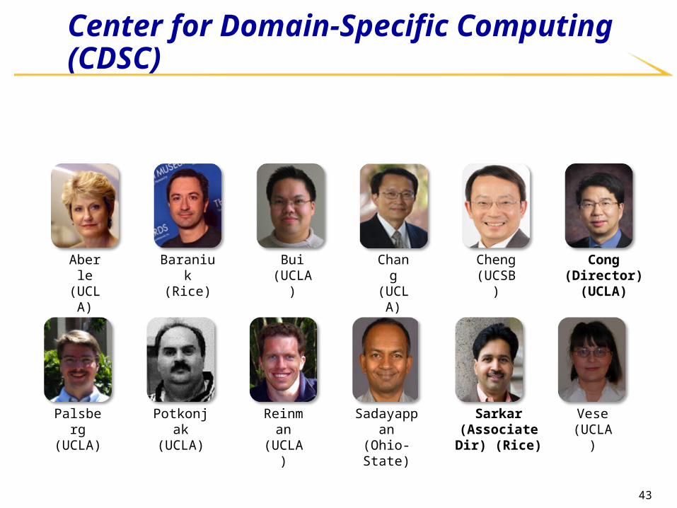
Center for Domain-Specific Computing (CDSC)
Reinman (UCLA)
Palsberg (UCLA)
Sadayappan (Ohio-State)
Sarkar(Associate Dir)
(Rice)
Vese (UCLA)
Potkonjak (UCLA)
Aberle (UCLA)
Baraniuk (Rice)
Bui (UCLA)
Cong (Director) (UCLA)
Cheng (UCSB)
Chang (UCLA)

44
CHP Mapping – Compilation and Runtime Software Systems CHP Mapping – Compilation and Runtime Software Systems for Customizationfor Customization
Goals: Efficient mapping of domain-specific specification to customizable hardware
– Adapt the CHP to a given application for drastic performance/power efficiency improvement
Domain-specific applications
Domain-specific applications
Abstract executionAbstract
execution ProgrammerProgrammer
Domain-specific programming model(Domain-specific coordination graph and domain-specific language extensions)
Source-to source CHP MapperSource-to source CHP Mapper
Application characteristics
CHP architecture models
C/C++ code
C/C++ front-endC/C++
front-end
Reconfiguring and optimizing back-endReconfiguring and optimizing back-end
Analysis annotations
Binary code for fixed & customized cores
Customized target code
RTL for programmable fabric
RTL Synthesizer
(xPilot)
RTL Synthesizer
(xPilot)
C/SystemC behavioral spec
Performance feedback
Adaptive runtimeLightweight threads and adaptive configuration
Adaptive runtimeLightweight threads and adaptive configuration
CHP architectural prototypes(CHP hardware testbeds, CHP simulation
testbed, full CHP)
CHP architectural prototypes(CHP hardware testbeds, CHP simulation
testbed, full CHP)

45
xPilot: Behavioral-to-RTL Synthesis Flow [SOCC’2006]
Behavioral spec. in C/C++/SystemC
RTL + constraints
SSDMSSDM
Arch-generation & RTL/constraints generation Verilog/VHDL/SystemC FPGAs: Altera, Xilinx ASICs: Magma, Synopsys, …
Advanced transformtion/optimizations Loop unrolling/shifting/pipelining Strength reduction / Tree height reduction Bitwidth analysis Memory analysis …
FPGAs/ASICsFPGAs/ASICs
Frontendcompiler
Frontendcompiler
Platform description
Core behvior synthesis optimizations Scheduling Resource binding, e.g., functional unit
binding register/port binding

46
AutoPilot Compilation Tool (based UCLA xPilot system)
Platform-based C to FPGA synthesis
Synthesize pure ANSI-C and C++, GCC-compatible compilation flow
Full support of IEEE-754 floating point data types & operations
Efficiently handle bit-accurate fixed-point arithmetic
More than 10X design productivity gain
High quality-of-results
C/C++/SystemCC/C++/SystemC
Timing/Power/Layout Timing/Power/Layout ConstraintsConstraints
RTL HDLs &RTL HDLs &RTL SystemCRTL SystemC
Platform Characterization
Library
FPGAFPGACo-ProcessorCo-Processor
=
Sim
ula
tion
, Verificatio
n, an
d
Pro
totyp
ing
Compilation & Compilation & ElaborationElaboration
Presynthesis OptimizationsPresynthesis Optimizations
Behavioral & CommunicationBehavioral & CommunicationSynthesis and OptimizationsSynthesis and Optimizations
AutoPilotTM
Co
mm
on
T
estben
ch
User ConstraintsUser Constraints
ES
L S
ynth
esis
Design Specification
Developed by AutoESL, acquired by Xilinx in Jan. 2011

47
Example: Versatile Scheduling Algorithm Based on SDC (DAC’06)Example: Versatile Scheduling Algorithm Based on SDC (DAC’06)
Scheduling problem in behavioral synthesis is NP-Scheduling problem in behavioral synthesis is NP-Complete under general design constraintsComplete under general design constraints
ILP-based solutions are versatile but very inefficientILP-based solutions are versatile but very inefficient Exponential time complexityExponential time complexity
Our solution: An efficient and versatile scheduler Our solution: An efficient and versatile scheduler based on SDC (system of difference constraints)based on SDC (system of difference constraints) Applicable to a broad spectrum of applicationsApplicable to a broad spectrum of applications
• Computation/Data-intensive, control-intensive, memory-Computation/Data-intensive, control-intensive, memory-intensive, partially timed.intensive, partially timed.
• Salable to large-size designs (finishes in a few seconds)Salable to large-size designs (finishes in a few seconds)
Amenable to a rich set of scheduling constraints:Amenable to a rich set of scheduling constraints:• Resource constraints, latency constraints, frequency Resource constraints, latency constraints, frequency
constraints, relative IO timing constraints.constraints, relative IO timing constraints.
Capable of a variety of synthesis optimizations:Capable of a variety of synthesis optimizations:• Operation chaining, pipelining, multi-cycle Operation chaining, pipelining, multi-cycle
communication, incremental scheduling, etc.communication, incremental scheduling, etc.
+4
+2
*5
*1
+3
CS0
* +
+3
*1
*5
+2
+4
CS1

48
Scheduling Scheduling Our Approach (DAC’06) Our Approach (DAC’06) Overall approachOverall approach
Current objective: high-performanceCurrent objective: high-performance Use a system of integer difference constraints to Use a system of integer difference constraints to
express all kinds of scheduling constraintsexpress all kinds of scheduling constraints Represent the design objective in a linear functionRepresent the design objective in a linear function
Dependency constraint Dependency constraint • vv11 v v33 : : xx33 – – xx11 0 0• vv22 v v33 : : xx33 – – xx22 0 0• vv33 v v55 : : xx44 – – xx33 0 0• vv44 v v55 : : xx55 – – xx44 0 0
Frequency constraint Frequency constraint • <<vv22 ,, v v55> : > : xx55 – – xx22 1 1
Resource constraintResource constraint• <<vv22 ,, v v33>: >: xx33 – – xx22 1 1
+ *
*
+v1v2
v3
v4
v5 Platform characterization:Platform characterization:• adder (+/–) 2nsadder (+/–) 2ns• multipiler (*): 5nsmultipiler (*): 5ns
Target cycle time: 10nsTarget cycle time: 10ns
Resource constraint: Only Resource constraint: Only ONE multiplier is availableONE multiplier is available
1 0 -1 0 0 0 1 -1 0 0 0 0 1 -1 0 0 0 0 1 -1 0 1 0 0 -1
X1
X2
X3
X4
X5
0-1 0 0-1
A x bTotally unimodular matrix: Totally unimodular matrix: guarantees integral solutionsguarantees integral solutions

49
Another Example: Efficient Pattern Mining [FPGA’08 and DATE’2010]
Programers may contain many patterns Prior work can only identify exact patterns We can efficiently identify “approximate” patterns in
large programs Based on the concept of editing distance
Use data-mining techniques
Efficient subgraph enumeration and pruning
Highly scalable – can handle programs with 100,000+ lines of code
Applications: Behavioral synthesis:
• 20+% area reduction due to sharing of approximate patterns
ASIP synthesis:
• Identify & extract customized instructions
+ +
<
+ +
-
+ +
-
Structure Variation
+ +
*
+ +
*
+ +
*
1616 1616
1616 3232
32323232 3232 3232
3232
+ +*
+ +*
+ +
*
Bitwidth Variation
Ports Variation

5050
Beyond C-to-RTL SynthesisBeyond C-to-RTL SynthesisCompilation Support for Hybrid Cache [DAC’2011]Compilation Support for Hybrid Cache [DAC’2011]
int amplitude[N]; // Global variableint state[N]; // Global variable...for (i = 0; i < N; ++i)
if( state[i] & pos )d += amplitude[i];
int amplitude[N]; // Global variableint state[N]; // Global variableint* SPM = &1itude[0];spm_pos(SPM);spm_size(2*N*sizof(int));...for (i = 0; i < N; ++i)
if( SPM[N+i] & pos)d += SPM[i];
SPM base address
SPM size
an SPM access
Manually coding ……RASP !

51
RASP (Reuse-Aware SPM Prefetching) flow Prefetch-enabled: hide memory access latency Reuse-enabled: reduce amount of data transfers
Compiler Support for Customizable Hybrid CacheCompiler Support for Customizable Hybrid Cache
Optimized Code for Hybrid Cache
Reuse Analysis
Reuse & Prefetching Co-Optimization
C/C++ ProgramHybrid Cache Configuration
Architecture Parameters
RASP
prefetch latencymaximal SPM size
Reuse Candidate
Graphs
LLVM-2.7 implementation
initiate SPM buffer size
update local/reuse regions of downstream vertices of v
caculate SPM utilization ratio r for inactive reuse dependency
exceed SPM size?
yes
no51
52
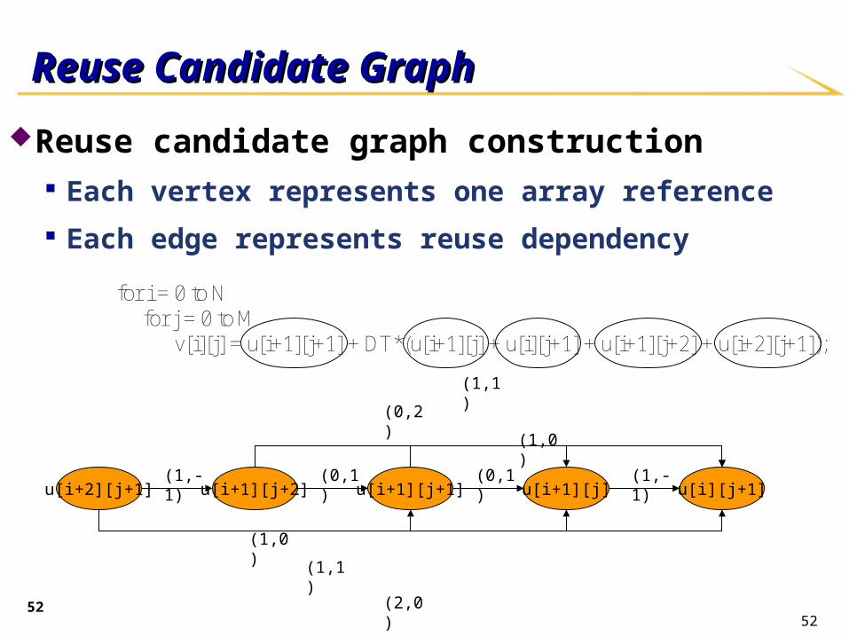
Reuse candidate graph construction Each vertex represents one array reference Each edge represents reuse dependency
52
u[i+1][j+1] u[i][j+1]u[i+1][j]
for i = 0 to N for j = 0 to M v[i][j] = u[i+1][j+1] + DT*(u[i+1][j] + u[i][j+1] + u[i+1][j+2] + u[i+2][j+1]);
u[i+1][j+2]u[i+2][j+1](0,1) (1,-1)(0,1)
(1,1)
(0,2)
(1,0)
(1,-1)
(1,0)
(1,1)
(2,0)
Reuse Candidate GraphReuse Candidate Graph

53
RASP Experimental ResultRASP Experimental Result
Performance and energy comparison
Average performance gain ~ 15.9%, 12.9% and 18.5%
Average energy gain ~ 22%, 31.2% and 10%53
54
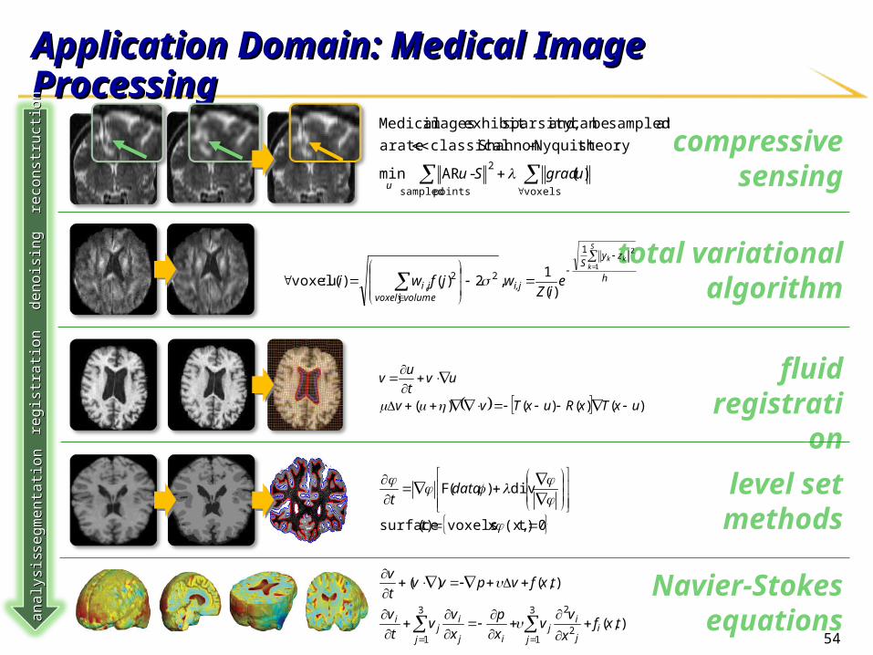
compressive sensing
level set methods
fluid registration
total variational algorithm
Application Domain: Medical Image ProcessingApplication Domain: Medical Image Processingde
noisi
ng
deno
ising
re
gist
ratio
nre
gist
ratio
nse
gmen
tatio
nse
gmen
tatio
nan
alys
isan
alys
is
h
zyS
i,jvolumevoxel
ji
S
kkk
eiZ
wjfwi
1
21
2
j
2, )(
1 ,2)()(u :voxel
)()()()( uxTxRuxTvv
uvt
uv
0t)(x, : xvoxels)(surface
div),(F
t
datat
3
12
23
1
),(
),()(
ji
j
ij
j ij
ij
i txfx
vv
x
p
x
vv
t
v
txfvpvvt
v
reco
nstru
ctio
nre
cons
truct
ion
voxels
2
points sampled
)(-ARmin
:theoryNyquist -Shannon classical rate aat sampled be can and sparsity,exhibit images Medical
ugradSuu
Navier-Stokes
equations

55
Will upgrade to HC-1 ex (with virtex 6) and fermi-
based Tesla card
Experimental Platform: Based on Convey HC-1
Xeon Dual Core LV513835W TDP
Tesla C1060100GB/s off-chip bandwidth200W TDP
4 XC5LX330 FPGAs80GB/s off-chip bandwidth90W Design Power
56
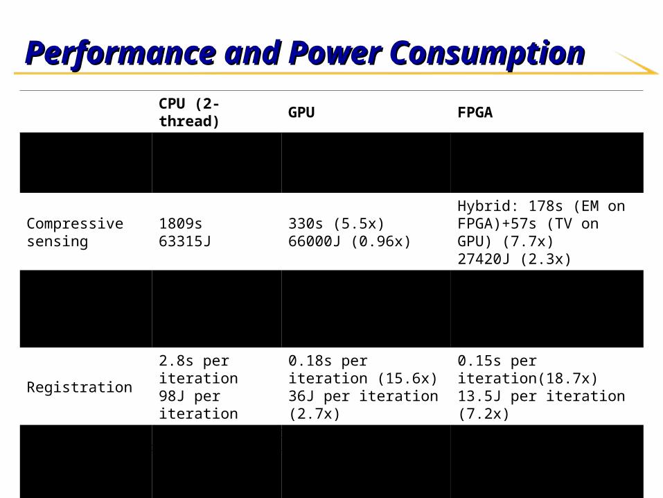
Performance and Power ConsumptionPerformance and Power Consumption
CPU (2-thread) GPU FPGA
Active power 35W (TDP) 200W(TDP) ~90W (4FPGAs)
Compressive sensing 1809s63315J
330s (5.5x)66000J (0.96x)
Hybrid: 178s (EM on FPGA)+57s (TV on GPU) (7.7x)27420J (2.3x)
Denoise 0.9s per iteration31.5J per iteration
0.02s per iteration (45x)4J per iteration (7.9x)
0.09s per iteration (10x)8.1J per iteration(3.9x)
Registration 2.8s per iteration98J per iteration
0.18s per iteration (15.6x)36J per iteration (2.7x)
0.15s per iteration(18.7x)13.5J per iteration (7.2x)
Segmentation 1.9s per iteration66.5J per iteration
0.05s per iteration (38x)10J per iteration (6.7x)
0.28s per iteration (6.8x)25.2J per iteration (2.6x)
Compressive sensing uses1283 dataset; all others use 2563 datasetFPGA-based compressive sensing and registration uses fixed-point

57
Concluding Remarks Despite of end of scaling, there is plenty of opportunity with Despite of end of scaling, there is plenty of opportunity with
customization and specialization for energy efficient computingcustomization and specialization for energy efficient computing
Many opportunities and challenges for architecture supportMany opportunities and challenges for architecture support Cores
Accelerators
Memory
Network-on-chips
Software support is also critical Software support is also critical

58
Acknowledgements
Reinman (UCLA)
Palsberg (UCLA)
Sadayappan (Ohio-State)
Sarkar(Associate Dir) (Rice)
Vese (UCLA)
Potkonjak (UCLA)
• A highly collaborative effort • thanks to all my co-PIs in four universities – UCLA, Rice, Ohio-State, and UC Santa Barbara
• Thanks the support from the National Science Foundation, GSRC, Intel, and Xilinx
Aberle (UCLA)
Baraniuk (Rice)
Bui (UCLA)
Cong (Director) (UCLA)
Cheng (UCSB)
Chang (UCLA)

59
Backup Slides

60
An overview of RASPAn overview of RASP
u[i+2][j+1]
u[i+1][j+2]
u[i+1][j+1]
u[i+1][j]
u[i] [j+1]
(1,-1) (0,1) (0,1) (1,-1)
(1,0)
(1,1)
(2,0)
(1,0)
(0,2)
(1,1)
u[i+2][j+1] u[i+1][j+2] u[i+1][j+1] u[i+1][j] u[i][j+1] SPM size
SPMSPM00 2121 2121 2121 2121 2121 105105
(N, M) =(256,256)
Prefetch latency: 20
SPMmax: 3KB
∆S = 257 ∆|LR| = 65025 ratio = 253
∆S = 256 ∆|LR| = 65280 ratio = 255
∆S = 512 ∆|LR| = 65024 ratio = 127
∆S = 257 ∆|LR| = 65025 ratio = 253
∆S = 256 ∆|LR| = 65280 ratio = 255 ∆S = 2 ∆|LR| = 65024 ratio = 32512
∆S = 255 ∆|LR| = 65025 ratio = 255
∆S = 1 ∆|LR|= 65280 ratio = 65280
∆S = 1 ∆|LR| = 65280 ratio = 65280
∆S = 255 ∆|LR| = 65025 ratio = 255
SPMSPM11 2121 2222 11 2121 2121 8686
∆S = 257 ∆|LR| = 65025 ratio = 253
∆S = 256 ∆|LR| = 65280 ratio = 255
∆S = 512 ∆|LR| = 65024 ratio = 127
∆S = 256 ∆|LR| = 65025 ratio = 254
∆S = 1 ∆|LR| = 1 ratio = 1
∆S = 1 ∆|LR| = 65024 ratio = 65024
∆S = 255 ∆|LR| = 65025 ratio = 255
∆S = 1 ∆|LR| = 1 ratio = 1
∆S = 255 ∆|LR| = 65025 ratio = 255
SPMSPM22 2121 2323 11 22 2121 6868
∆S = 257 ∆|LR| = 65025 ratio = 253
∆S = 256 ∆|LR| = 65280 ratio = 255
∆S = 512 ∆|LR| = 65024 ratio = 127
∆S = 255 ∆|LR| = 65025 ratio = 255
∆S = 1 ∆|LR| = 1 ratio = 1
∆S = 255 ∆|LR| = 65025 ratio = 255
∆S = 1 ∆|LR| = 1 ratio = 1
∆S = 255 ∆|LR| = 2 ratio = 0.01
∆S = 257 ∆|LR| = 65025 ratio = 253
∆S = 256 ∆|LR| = 65280 ratio = 255
∆S = 512 ∆|LR| = 65024 ratio = 127
∆S = 255 ∆|LR| = 65025 ratio = 255
∆S = 1 ∆|LR| = 1 ratio = 1
∆S = 255 ∆|LR| = 65025 ratio = 255
∆S = 1 ∆|LR| = 1 ratio = 1
∆S = 255 ∆|LR| = 2 ratio = 0.01
SPMSPM33 2121 278278 11 22 2121 323323
Less than 3KB SPM, reduce ~60% data transfers !Less than 3KB SPM, reduce ~60% data transfers !
initiate SPM buffer size update SPM utilization ratio for downstream vertices of v
caculate SPM utilization ratio r for unactive reuse edges
60

61
CDSC Simulation FrameworkCDSC Simulation Framework
OPAL(Timing model of processor)
RUBY(Timing model
of memory)
GARNET(Timing model of interconnection)
WATTCH(Power model of
processor)
SIMICS(Functional
model)
Heterogeneity
Tightly-coupled accelerator
Loosely-coupled accelerator
Dynamic NUCA
Scratchpad Memory
Customized routing for irregular
NoC
RF-I shortcut
Processor Power/Area
Model (Interface to McPAT)
Accelerator Power/Area Model (Interface to
AutoPilot)
Hierarchical RF-I enabled coherence protocol

62
Automatic Memory Partitioning [ICCAD09] Memory system is critical for high
performance and low power design Memory bottleneck limits maximum
parallelism Memory system accounts for a significant
portion of total power consumption
Goal Given platform information (memory port,
power, etc.), behavioral specification, and throughput constraints• Partition memories automatically • Meet throughput constraints• Minimize power consumption
A[i]A[i] A[i+1]A[i+1]
for (int i =0; i < n; i++)for (int i =0; i < n; i++)… … = A[i]+A[i+1]= A[i]+A[i+1]
(a) C code
R1 R2
A[0, 2, 4,…]A[0, 2, 4,…] A[1, 3, 5…]A[1, 3, 5…]
Decoder
(b) Scheduling
(c) Memory architecture after partitioning

63
Automatic Memory Partitioning (AMP) Techniques
Capture array access confliction in conflict graph for throughput optimization
Model the loop kernel in parametric polytopes to obtain array frequency
Contributions Automatic approach for
design space exploration Cycle-accurate Handle irregular array
accesses Light-weight profiling for
power optimization
Loop NestLoop Nest
Array Subscripts AnalysisArray Subscripts Analysis
Memory Platform Memory Platform InformationInformation
Partition Candidate GenerationPartition Candidate Generation
Try Partition Candidate CTry Partition Candidate Cii, ,
Minimize Accesses on Each BankMinimize Accesses on Each Bank
Meet Port Limitation?Meet Port Limitation?
Loop Pipelining and SchedulingLoop Pipelining and Scheduling
Pipeline ResultsPipeline Results
N
Power OptimizationPower Optimization
Y
Throughput Optimization

64
Automatic Memory Partitioning (AMP)
Original Partition Original Partition Area Power II II SLICES SLICES Comparsion Reduction
fir 3 1 241 510 2.12 26.82%idct 4 1 354 359 1.01 44.23%litho 16 1 1220 2066 1.69 31.58%matmul 4 1 211 406 1.92 77.64%motionEst 5 1 832 961 1.16 10.53%palindrome 2 1 84 65 0.77 0.00%avg 5.67x 1.45 31.80%
About 6x throughput improvement on average with 45% area
overhead
In addition, power optimization can further reduced 30% of power
after throughput optimization

65
Experimental Results - Increasing request for accelerator Experimental Results - Increasing request for accelerator
Flat speedup compare to OS-based approach when increasing the number of request for accelerators
• 8 cores, 1 accelerator• Slowdown due to accelerators sharing

66
Experimental results – Estimation ErrorsExperimental results – Estimation Errors
* Very low estimation error for both core and GAM (maximum 6% error, average 3% for core, 2% for GAM)* Decreasing GAM estimation error because of the canceling effect