1 agbell – eect 111 1 by andrew g. bell [email protected] (260) 481-2288 lecture 2
TRANSCRIPT

1AGBell – EECT 111
AGBell – EECT 111
1AGBell – EECT 111
by Andrew G. [email protected]
(260) 481-2288
Lecture 2

2AGBell – EECT 111
AGBell – EECT 111
2AGBell – EECT 111
CHAPTER 2
Electrical Quantities
and Components

3AGBell – EECT 111AGBell – EECT 111
3
Conductance
• Definition: Ability to allow current to flow
• Relationship to Resistance: Opposite of resistance
• Unit of Measure: Siemens (S)

4AGBell – EECT 111AGBell – EECT 111
4
Electrical Units and Abbreviations
Unit Measure Symbol
Potential Volt V
Current Ampere A
Resistance Ohm Conductance Siemens S
5AGBell – EECT 111AGBell – EECT 111
5
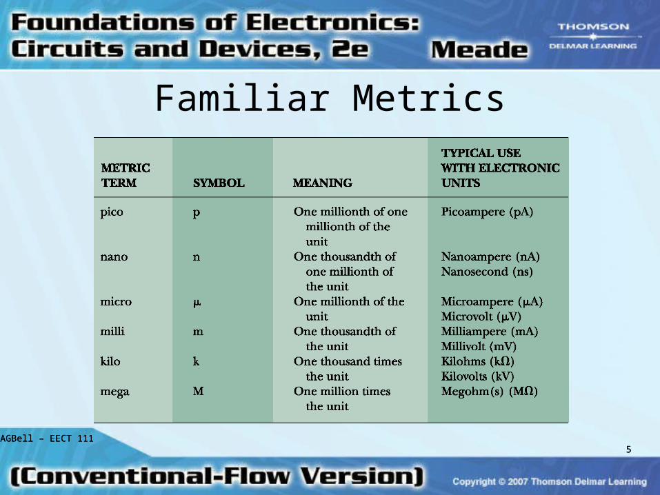
Familiar Metrics

6AGBell – EECT 111AGBell – EECT 111
6
Conductors
• Function:– To carry electrical energy from one point
to another or to provide a path for electrical current flow between components or circuits
• Numerous Types of Conductors– Determined by the nature of application
and the amount of current to be carried

7AGBell – EECT 111AGBell – EECT 111
7
Conductors (cont.)
• Ways of classifying conductors include:– Type of metal used– Size of the wire – Form of the wire (solid, stranded, or
braided)– Number of conductors used – Insulation characteristics

8AGBell – EECT 111AGBell – EECT 111
8
Superconductivity
• All conductors have some resistance at normal operating temperatures.
• Superconductivity: – Current flow through a material with nearly
zero resistance– Only occurs in certain materials– Only occurs at extremely cold temperatures
(e.g., –273°C)

9AGBell – EECT 111AGBell – EECT 111
9
Superconductivity (cont.)
• Certain ceramic materials have very low resistance at temperatures much higher than absolute zero (–273°C).– Low resistance at higher temperatures makes it
easier to take advantage of superconductivity.
• Some future possibilities:– More efficient motors and generators– Faster computers

10AGBell – EECT 111AGBell – EECT 111
10
Physical Factors of Conductors
• Factors that influence resistance:– Type of material– Length of conductor– Cross-sectional area of wire– Temperature of wire
• Temperature coefficients

11AGBell – EECT 111AGBell – EECT 111
11
Physical Factors of Conductors (cont.)
• Resistivity– Characteristic resistance in ohms of a
given material per standard length (meters or mils) and cross-sectional area (square meters or circular mils)
– Different materials have different resistivity characteristics.

12AGBell – EECT 111AGBell – EECT 111
12
Characteristics of Wire
• Standardized wire sizing by the American Standard Wire Gauge (AWG)
• Current-handling capabilities
• Types: Stranded and solid
• Resistance: Determined by material, length and cross-sectional area of the wire
A
lR

13AGBell – EECT 111
Resistors• Definition:
– Devices which oppose current
• Purpose:– To limit current and
divide voltage
• Types:– Fixed – Variable
14AGBell – EECT 111AGBell – EECT 111
14
Resistor Size
• The physical size of the resistor determines its ability to handle heat.
• The difference between a carbon or a chip resistor and a wire-wound resistor is merely its ability to handle current flow.
• Wire-wound resistors are designed to handle more heat than carbon or chip resistors.

15AGBell – EECT 111AGBell – EECT 111
15
Common Resistor Types
• Fixed Resistors:– One value only– Common values available– Value determined by color coding– Variety of wattage ratings– Quality ratings vary widely

16AGBell – EECT 111AGBell – EECT 111
16
Variable Resistors
• Potentiometer:– Variable from 0 ohms to labeled value– Popular due to flexibility– Found in use as volume controls– Physical sizes available vary widely– Resistance values vary widely– Resistance value generally stamped

17AGBell – EECT 111AGBell – EECT 111
17
Resistor Type Summary
• Wire-wound: High wattage
• Potentiometer: Variable resistance values
• Rheostat: Alternative to potentiometer
• Chip Resistor: Small size, common in compact circuits
• Carbon Composition: Fixed value, common, inexpensive
• Precision: Accurately controlled values

18AGBell – EECT 111AGBell – EECT 111
18
The Resistor Color Code
• Purpose: Indicate value efficiently
• Values: Standard values available
• Color Bands: Used to indicate value
• Tolerance: Indicates acceptable variance

19AGBell – EECT 111AGBell – EECT 111
19
Four Band Color Code
• First band indicates first significant number in value.
• Second band indicates second significant number in value.
• Third band indicates multiplier.
• Fourth band indicates tolerance.

20AGBell – EECT 111AGBell – EECT 111
20
Example Color Coding
Color Code Resistor Value
Red, Red, Orange, Gold 22 k ± 5%
Orange, Red, Brown, Silver
320 ± 10%
Yellow, Violet, Yellow,
Gold
470 k ± 5%

21AGBell – EECT 111AGBell – EECT 111
21
Five Band Color Code• First band indicates first significant number in
value.
• Second band indicates second significant number in value.
• Third band indicates third significant number in value.
• Fourth band indicates multiplier.
• Fifth band indicates tolerance.

22AGBell – EECT 111AGBell – EECT 111
22
Example Color Coding
Color Code Resistor Value
Red, Red, Red, Orange, Red
222 k ± 2%
Orange, Red, Blue,
Brown, Green
3.260 k ± 0.5%
Yellow, Violet, Yellow,
Red, Violet
47.4 k ± 0.1%
23AGBell – EECT 111AGBell – EECT 111
23
Resistor Tolerance
• Definition: The range of acceptable values
• Common tolerance values for four banded resistors: 20%, 10%, 5%
• Precision tolerance values for five banded resistors: 2%, 1%, 0.5%, 0.25%, 0.1%

24AGBell – EECT 111AGBell – EECT 111
24
Example of Tolerance
• Resistor Colors: Brown, Black, Brown, Gold
• Brown, Black, Brown = 100 ohms
• Gold = +/-5%
• Upper Limit = 100 + 5 = 105 ohms
• Lower Limit = 100 – 5 = 95 ohms

25AGBell – EECT 111AGBell – EECT 111
25
Typical Meters

26AGBell – EECT 111AGBell – EECT 111
26
Measuring Voltage with Meters
• Set meter to voltage function and proper range.
• Connect the meter test leads to the two points you wish to measure (across the device). The red or positive lead should be closest to the positive terminal of the source.
• The measured voltage will be displayed.

27AGBell – EECT 111AGBell – EECT 111
27
Measuring Resistance with Meters
• Remove power source.
• Set meter to resistance function and proper range.
• Meter leads are used like voltmeter.
• Isolate the component to be measured.
• Precautions: Power must be OFF!
28AGBell – EECT 111AGBell – EECT 111
28
Measuring Current with Meters
• Set meter to voltage function and proper range. Change position of the red lead for most meters.
• Break the circuit and insert meter test leads in line (series) with the current path.
• Precaution: Connection to circuit is critical!

29AGBell – EECT 111AGBell – EECT 111
29
Schematic Symbols
• Voltmeter:
• Ohmmeter:
• Ammeter :
V
A

30AGBell – EECT 111AGBell – EECT 111
30
The Schematic Diagram
• Wiring Conventions: – Connection/No connection
• The Switch– Basic On/Off
• The Resistor:– Fixed and Variable

31AGBell – EECT 111AGBell – EECT 111
31
The Circuit