1 – about sips and csips technologies/about...1 – about sips and csips ... we first review the...
TRANSCRIPT
18
1 – About SIPs and CSIPs
This report focuses on a relatively new technology and a relatively small industry within the larger scope
of the building community. In addition, by addressing cementitious-faced SIPs, this report addresses an
even narrower segment.
To put this report in perspective, we first review the current status and practices of the SIP industry.
1.1 – What are SIPs and CSIPs?
SIPs are high-performance composite
building panels used in floors, walls, and
roofs for residential and light commercial
buildings. These panels are fabricated in a
factory and shipped to a construction site,
where they can be quickly assembled to
form a tight, energy-efficient building
envelope.
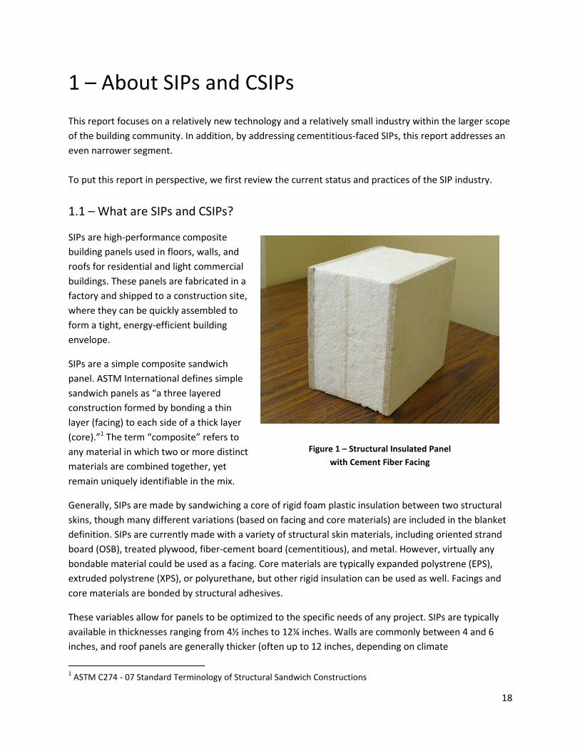
SIPs are a simple composite sandwich
panel. ASTM International defines simple
sandwich panels as “a three layered
construction formed by bonding a thin
layer (facing) to each side of a thick layer
(core).”1 The term “composite” refers to
any material in which two or more distinct
materials are combined together, yet
remain uniquely identifiable in the mix.
Generally, SIPs are made by sandwiching a core of rigid foam plastic insulation between two structural
skins, though many different variations (based on facing and core materials) are included in the blanket
definition. SIPs are currently made with a variety of structural skin materials, including oriented strand
board (OSB), treated plywood, fiber-cement board (cementitious), and metal. However, virtually any
bondable material could be used as a facing. Core materials are typically expanded polystrene (EPS),
extruded polystrene (XPS), or polyurethane, but other rigid insulation can be used as well. Facings and
core materials are bonded by structural adhesives.
These variables allow for panels to be optimized to the specific needs of any project. SIPs are typically
available in thicknesses ranging from 4½ inches to 12¼ inches. Walls are commonly between 4 and 6
inches, and roof panels are generally thicker (often up to 12 inches, depending on climate
1 ASTM C274 - 07 Standard Terminology of Structural Sandwich Constructions
Figure 1 – Structural Insulated Panel
with Cement Fiber Facing
19
conditions). SIPs with cementitious facings are
typically cut to 4 feet by 8 feet. SIPs may be as
large as 9 feet by 28 feet with OSB facings.
Custom sizes are also available, and many
manufacturers offer curved SIPs for curved
roof applications.2
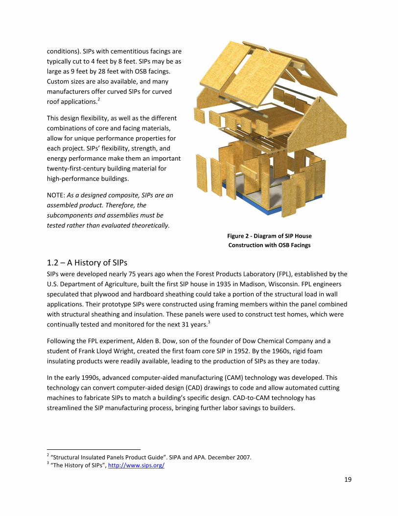
This design flexibility, as well as the different
combinations of core and facing materials,
allow for unique performance properties for
each project. SIPs’ flexibility, strength, and
energy performance make them an important
twenty-first-century building material for
high-performance buildings.
NOTE: As a designed composite, SIPs are an
assembled product. Therefore, the
subcomponents and assemblies must be
tested rather than evaluated theoretically.
1.2 – A History of SIPs
SIPs were developed nearly 75 years ago when the Forest Products Laboratory (FPL), established by the
U.S. Department of Agriculture, built the first SIP house in 1935 in Madison, Wisconsin. FPL engineers
speculated that plywood and hardboard sheathing could take a portion of the structural load in wall
applications. Their prototype SIPs were constructed using framing members within the panel combined
with structural sheathing and insulation. These panels were used to construct test homes, which were
continually tested and monitored for the next 31 years.3
Following the FPL experiment, Alden B. Dow, son of the founder of Dow Chemical Company and a
student of Frank Lloyd Wright, created the first foam core SIP in 1952. By the 1960s, rigid foam
insulating products were readily available, leading to the production of SIPs as they are today.
In the early 1990s, advanced computer-aided manufacturing (CAM) technology was developed. This
technology can convert computer-aided design (CAD) drawings to code and allow automated cutting
machines to fabricate SIPs to match a building’s specific design. CAD-to-CAM technology has
streamlined the SIP manufacturing process, bringing further labor savings to builders.
2 “Structural Insulated Panels Product Guide”. SIPA and APA. December 2007.
3 “The History of SIPs”, http://www.sips.org/
Figure 2 - Diagram of SIP House
Construction with OSB Facings
20
This development coincided with SIPA’s formation in 1990. SIPA was formed to provide support and
visibility for those manufacturing and building with this emerging building technology and to increase
SIPs’ market share through a partnership with the Engineered Wood Association (APA).
Taking advantage of the building industry’s growing interest in energy efficiency, SIPA collaborated with
the Partnership for Advanced Housing Technology to “develop a set of prescriptive performance
standards, which were submitted for inclusion in the International Code Council’s Residential Code
(IRC).”4 On May 22, 2007, structural insulated panel wall systems were adopted into the IRC. Section
R614 of the 2007 IRC Supplement and subsequent editions of the code include prescriptive standards
for SIP wall construction. The IRC Prescriptive Method for SIPs is attached as Appendix A. For more
information regarding the adoption of SIPs in building codes, as well as how this changes the design
decision process, see section 2.2.
Today, SIPs offer a high-tech solution for residential and low-rise nonresidential buildings, with a great
potential for multistory building applications.
1.3 – Current Material Options in the SIP Industry
A closer examination of SIP’s three components—the structural facing, insulating core, and adhesive
holding the pieces together—yields a greater understanding of their potential. The variety of available
materials allows panels to be tailored to each project and component materials to complement each
other, making the design of SIPs both a material selection problem and a dimensional problem. For
example, increasing the core thickness to obtain the proper design values can compensate for facing
materials that lack rigidity. This flexibility allows materials to be chosen for reasons other than
mechanical performance.
The rapid development of new technologies makes for new possibilities, and the material options are
essentially boundless. Thus, this review cannot touch on every available option. Instead, it includes the
most common and readily available material options currently used in the SIP industry and highlights the
material options focused upon in this research.
1.3.1 – Facing Materials
Ideally, SIP facings should have high stiffness (high flexural rigidity), high tensile and compressive
strength, high impact resistance, quality surface finish, resistance to environmental impacts (e.g.,
chemical, UV, heat, etc.), and durability.5
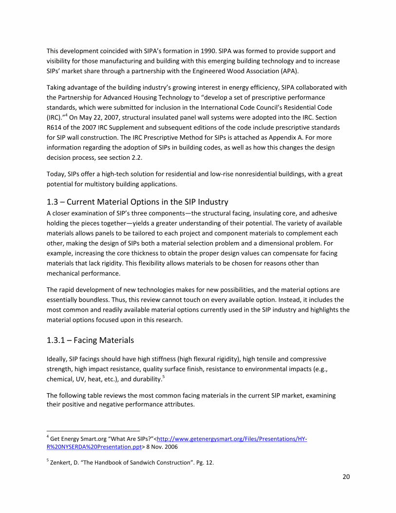
The following table reviews the most common facing materials in the current SIP market, examining
their positive and negative performance attributes.
4 Get Energy Smart.org “What Are SIPs?”<http://www.getenergysmart.org/Files/Presentations/HY-
R%20NYSERDA%20Presentation.ppt> 8 Nov. 2006
5 Zenkert, D. “The Handbook of Sandwich Construction”. Pg. 12.
21
Common SIP Facing Materials
Material Pros Cons
Oriented Strand
Board
• Inexpensive
• Readily available
• Recognized in current IRC
code
• Requires finishing on interior and
exterior
• Swells with moisture
Cement Fiber • Will not rot, burn, or corrode
• Acts as a finished interior and
exterior
• More durable and lasts longer
• Heavier than other options and more
difficult to handle
• Brittle and prone to cracking during
shipment
• More expensive than OSB
Metal • Inexpensive
• Readily available
• More durable and lasts longer
• Requires finishing on interior and
exterior
Others Magnesium oxide board, fiber-reinforced polymers
Table 1 – Common SIP Facing Materials
OSB facings are used for the vast majority of SIPs. OSB is an engineered wood product made from cross-
oriented layers of thin, rectangular wooden strips compressed and bonded together with wax and resin
adhesives. OSB has been extensively tested as a load-bearing material and is commonly available in
large sizes. In addition, the Prescriptive Method Supplement to the IRC (discussed in the next chapter)
requires OSB facings for SIPs to be recognized in the code for one- to two-story residential buildings.
Metal SIP manufacturers often use aluminum as a skin material. This structural panel system is used in
both residential sites, such as carports or walkways, as well as industrial systems, such as the
construction of cold storage facilities. Panel designers sometimes take advantage of their aluminum
siding and connect panels metal to metal with pop rivets. Another option is a cam-lock system or a
system in which internal gutters allow the panels to be reversed.
Fiber-cement board faced SIPs, referred to as CSIPs, are the focus of this research. CSIPs constitute a
smaller portion of the market than OSB faced SIPs, but they carry many added benefits. CSIPs are
typically manufactured from cellulose-reinforced cement boards for inside and outside skins, commonly
referred to as “fiber-reinforced cement,” or simply “fiber cement.” Table 2 – Required Evaluation of
Cement Fiber Panels” lists required testing.
Fiber-cement panels can have different finished looks, such as a wood grain, stucco, or smooth.6 This
removes the need for CSIPs to be finished on the interior or exterior, making it the entire wall assembly
6 http://www.toolbase.org/Building-Systems/Whole-House-Systems/fiber-cement-faced-sips
22
and removing the need for several steps in the construction process. If CSIPs are used as the interior
finish surface, they must comply with the appropriate fire codes. Where used as the exterior finish
surface, fiber-cement board must be tested for weather resistance, transverse and racking loading, and
fire resistance.
In addition to providing an interior and exterior finish, buildings constructed with CSIPs typically will last
longer and require less maintenance than those built with other types of SIPs. Fiber cement boards have
a high resistance to moisture absorption, will not support black mold growth, and are rot and vermin
resistant. CSIPs have a higher fire rating than OSB-faced SIPs, and in most residential applications, no
drywall is necessary. This lack or drywall requirements is determined by the fire-requirements of the
applicable building code. See Section 2.2.8 for a more detailed discussion of fire code requirements and
limitations of CSIPs.
While there are many benefits to CSIPs, there are negative aspects as well. CSIPs are significantly heavier
than OSB SIPs. A 4’x8’ CSIP panel weighs roughly 180 lbs., while a 4’x8’ OSB SIP weighs 111 lbs. This
makes CSIPs more cumbersome during construction. In addition, due to the free silica—a health hazard
if inhaled—contained in most cement fiber, in-field modifications (especially with rotary saws) should be
avoided.
The final difficulty with CSIPs is the relative infancy of the industry. Since few CSIP manufacturers and
large-scale organizations exist, CSIP prices are higher for the consumer than need be, and service is less
reliable and consistent.
23
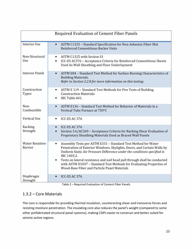
Required Evaluation of Cement Fiber Panels
Interior Use • ASTM C1325 – Standard Specification for Non-Asbestos Fiber-Mat Reinforced Cementitious Backer Units
Non-Structural Use
• ASTM C1325 with Section S1
• ICC-ES AC376 – Acceptance Criteria for Reinforced Cementitious Sheets Used As Wall Sheathing and Floor Underlayment
Interior Finish • ASTM E84 – Standard Test Method for Surface Burning Characteristics of Building Materials. Refer to Section 2.2.8 for more information on this testing.
Construction Types
• ASTM E 119 – Standard Test Methods for Fire Tests of Building Construction Materials
• IBC Table 601.
Non-Combustible
• ASTM E136 – Standard Test Method for Behavior of Materials in a Vertical Tube Furnace at 750°C
Vertical Use • ICC-ES AC 376
Racking Strength
• ICC-ES AC 376
• Section 3.6/AC269 – Acceptance Criteria for Racking Shear Evaluation of Proprietary Sheathing Materials Used as Braced Wall Panels
Water Resistive Barrier
• Assembly Tests per ASTM E331 – Standard Test Method for Water Penetration of Exterior Windows, Skylights, Doors, and Curtain Walls by Uniform Static Air Pressure Difference under the conditions specified in IBC 1403.2.
• Tests on lateral resistance and nail head pull through shall be conducted with ASTM D1037 – Standard Test Methods for Evaluating Properties of Wood-Base Fiber and Particle Panel Materials
Diaphragm Strength
• ICC-ES AC 376
Table 2 – Required Evaluation of Cement Fiber Panels
1.3.2 – Core Materials
The core is responsible for providing thermal insulation, counteracting shear and transverse forces and
resisting moisture penetration. The insulating core also reduces the panel’s weight (compared to some
other prefabricated structural panel systems), making CSIPs easier to construct and better suited for
seismic-active regions.
24
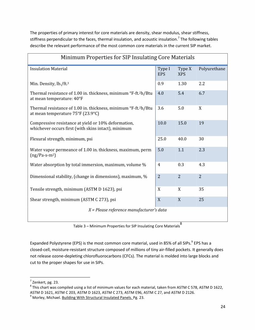
The properties of primary interest for core materials are density, shear modulus, shear stiffness,
stiffness perpendicular to the faces, thermal insulation, and acoustic insulation.7 The following tables
describe the relevant performance of the most common core materials in the current SIP market.
Minimum Properties for SIP Insulating Core Materials
Insulation Material Type I EPS
Type X XPS
Polyurethane
Min. Density, lb./ft.3 0.9 1.30 2.2
Thermal resistance of 1.00 in. thickness, minimum °F-ft.2h/Btu at mean temperature: 40°F
4.0 5.4 6.7
Thermal resistance of 1.00 in. thickness, minimum °F-ft.2h/Btu at mean temperature 75°F (23.9°C)
3.6 5.0 X
Compressive resistance at yield or 10% deformation, whichever occurs first (with skins intact), minimum
10.0 15.0 19
Flexural strength, minimum, psi 25.0 40.0 30
Water vapor permeance of 1.00 in. thickness, maximum, perm (ng/Pa-s-m2)
5.0 1.1 2.3
Water absorption by total immersion, maximum, volume % 4 0.3 4.3
Dimensional stability, (change in dimensions), maximum, % 2 2 2
Tensile strength, minimum (ASTM D 1623), psi X X 35
Shear strength, minimum (ASTM C 273), psi X X 25
X = Please reference manufacturer’s data
Table 3 – Minimum Properties for SIP Insulating Core Materials8
Expanded Polystyrene (EPS) is the most common core material, used in 85% of all SIPs.9 EPS has a
closed-cell, moisture-resistant structure composed of millions of tiny air-filled pockets. It generally does
not release ozone-depleting chlorofluorocarbons (CFCs). The material is molded into large blocks and
cut to the proper shapes for use in SIPs.
7 Zenkert, pg. 23.
8 This chart was compiled using a list of minimum values for each material, taken from ASTM C 578, ASTM D 1622,
ASTM D 1621, ASTM C 203, ASTM D 1623, ASTM C 273, ASTM E96, ASTM C 27, and ASTM D 2126. 9 Morley, Michael. Building With Structural Insulated Panels. Pg. 23.
25
The IRC Prescriptive Method requires that SIPs use molded EPS as a core material. This EPS must meet
the requirements of ASTM C 578 (referenced in “Minimum Properties for SIP Insulating Core Materials”),
a consensus document developed by producers of polystyrene foam, third-party testing companies,
regulatory agencies, and insulation users in North America. It covers the types, physical properties, and
dimensions of cellular polystyrene used as thermal insulation for temperatures from -65°F to 165°F.
Flame spread rating of SIP cores must be less than 75 and the smoke-development rating shall be less
than 450, as tested in accordance with ASTM E 84. This does not mean all SIPs must use EPS, but if
another material is used, it must be shown to be of equal or better performance by a professional
engineer.
Extruded Polystyrene (XPS) is similar to EPS, but is not used nearly as frequently within the SIP industry.
XPS performs almost twice as well as EPS in regards to compressive strength, flexural strength, and
shear resistance. However, these benefits come at a significant cost: sheets of XPS are far more
expensive, can only be made four inches thick, and do not create a perfectly flat gluing surface. Because
of these drawbacks, XPS is used infrequently in the SIP industry.
Polyurethane or polyisocyanurate (both commonly referred to as urethane) is also used by
manufacturers as an insulating material. Liquid foam is injected between two skins under considerable
pressure, which hardens to produce a strong bond between the foam core and the skins. The foam core
contains a blowing agent, some of which escapes over time, reducing the initial R-value of the SIP from
about R-9 to R-7 per inch (2.5 cm) of thickness. Wall panels made of polyisocyanurate or polyurethane
are typically 3.5 inches (89 mm) thick. Ceiling panels are up to 7.5 inches (190 mm) thick. These panels,
although more expensive, are more fire-resistant and water vapor-diffusion-resistant than EPS.10
1.3.3 – Adhesives
The final component of a SIP assembly is the adhesive that bonds the facing and core materials. As with
facing and core materials, there are several options for adhesive. No matter which option is chosen, this
glue must:
• Resist Forces: The adhesive joint must be able to transfer the design loads (have the desired
tensile and shear strength). They must resist buckling and racking forces.
• Thermal stresses: A frequent cause of debonding (and catastrophic failure of the panel) is due to
thermal stress.
• Moisture Penetration: The adhesive must be able to withstand any sort of moisture penetration
into the joint without delamination or bond failure.
Other variables of adhesive performance that must be considered include preparation requirements for
application, required bonding pressure, adhesive viscosity, bond thickness, viscoelastic properties, and
curing shrinkage.
10
http://www.eere.energy.gov/
26
Defining the common performance properties of available adhesives is difficult because each is a
proprietary material. However, any adhesive used in the construction of a SIP must comply with
International Code Council Acceptance Criteria AC05.
1.4 – Factory Fabrication
SIPs and CSIPs are prefabricated under factory-controlled settings prior to use on a building site. The
only code requirement for SIP fabrication is that the process must conform to quality documentation in
accordance with ICC Acceptance Criteria 10. Despite proprietary variations from manufacturer to
manufacturer, the process is relatively similar throughout the industry.
Prior to SIP fabrication, shop drawings are created for the panels, detailing exactly how each panel will
fit into the overall building design. A count of the required panels, their dimensions, and special cuts
(such as windows and doors) is created, and each panel is made specifically for its purpose within the
building.
Typically, fabricating EPS- and XPS-core SIPs begins by placing one facing out on the assembly area. The
desired thickness of core material is run through a glue-spreading machine, where the appropriate
amount of glue is spread on both sides of the core. The core section is then placed on top of the bottom
facing, and a top facing is positioned above it. This assembly is moved into a press, which applies even
pressure to the top and bottom facings. Specific adhesives require different pressure, curing time,
temperature, and humidity, all of which are controlled.
After the panels are removed from the press, they are set aside to cure for 24 hours. Once cured, they
are moved to the fabrication section of the plant, where windows, doors, electrical chases, and other
openings specific to the project are prepared.
The approach to urethane panels is rather different. Panel facings are separated at the required distance
by spacers, and the mixed components of the foam core are injected between the facings. As the foam
expands and fills the void, the foam bonds the two facings together without the need for an adhesive.
1.4.1 – CSIP Plant Optimization
Although the manufacturing of CSIPs is typologically similar to wood SIP manufacturing, the plant should
address the following key issues and concerns:
• Dust control: dust created by fiber cement contains free silica, which can result in silicosis if
inhaled. Dust control for the fabrication and handling of FCB is critical.
• Smaller unit sizes: FCB comes in dimensions of 4’x8’, 4’x10’, and 4’x12’, while OSB ranges as high
as 8’x24’.
• Higher weights per unit size: FCB is denser than OSB.
• Optimization of shop drawings to reduce fabrication.
27
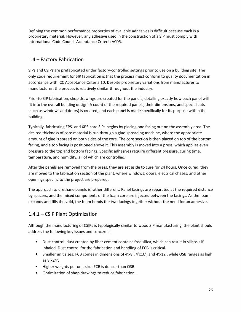
Illustrated below is a 10,000 square foot SIP operation capable of producing roughly 1Mn square feet of
panels per year (or roughly 250 to 300 affordable single-family homes per year). The capital costs in
equipment are in the four SIP presses (roughly $25K each), the glue spreader (roughly $5K), the
equipment to properly cut EPS to the desired size (roughly $5K), the vertical panel saw (roughly $5K) and
the CNC machines (roughly $15K each). The total investment required is roughly $150K.
Figure 3 – Basic CSIP Manufacturing and Fabricating
This plant has three major zones: lamination (where the panels are laminated, denoted by A, B, C), basic
fabrication (where the panels are cut, denoted by D), and final fabrication (where the panels are
finished, labeled, organized, and shipped, denoted by E, F). These areas are outlined in the floor colors.
28
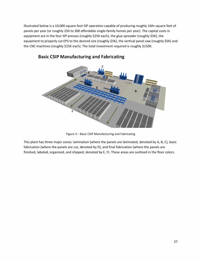
Figure 4 - Lamination
The process flow through the factory starts with the EPS station, where large blocks of EPS are
inventoried and cut down to the desired panel size and thickness. Inventorying large blocks of foam is
more cost-effective than inventorying various sizes of foam. This station’s primary tool is a hot wire
station (1) that can rapidly tool the foam. From this station, the foam is delivered to the individual panel
presses (3).
The panel presses (3) are hydraulic presses that deliver a consistent amount of pressure to properly
adhere the foam and the facing. Because the glue is exothermic and expansive, the press must offset
this pressure. Large bundles of fiber-cement board, which by themselves are extremely heavy, are pre-
positioned at the head of the presses to reduce time and fatigue. Additionally, the mobile glue spreader
(2) is prepositioned near the press and foam to decrease travel distances. The presses should contain
built-in pallets, so removing the CSIPs from the presses is a nominal task.
29
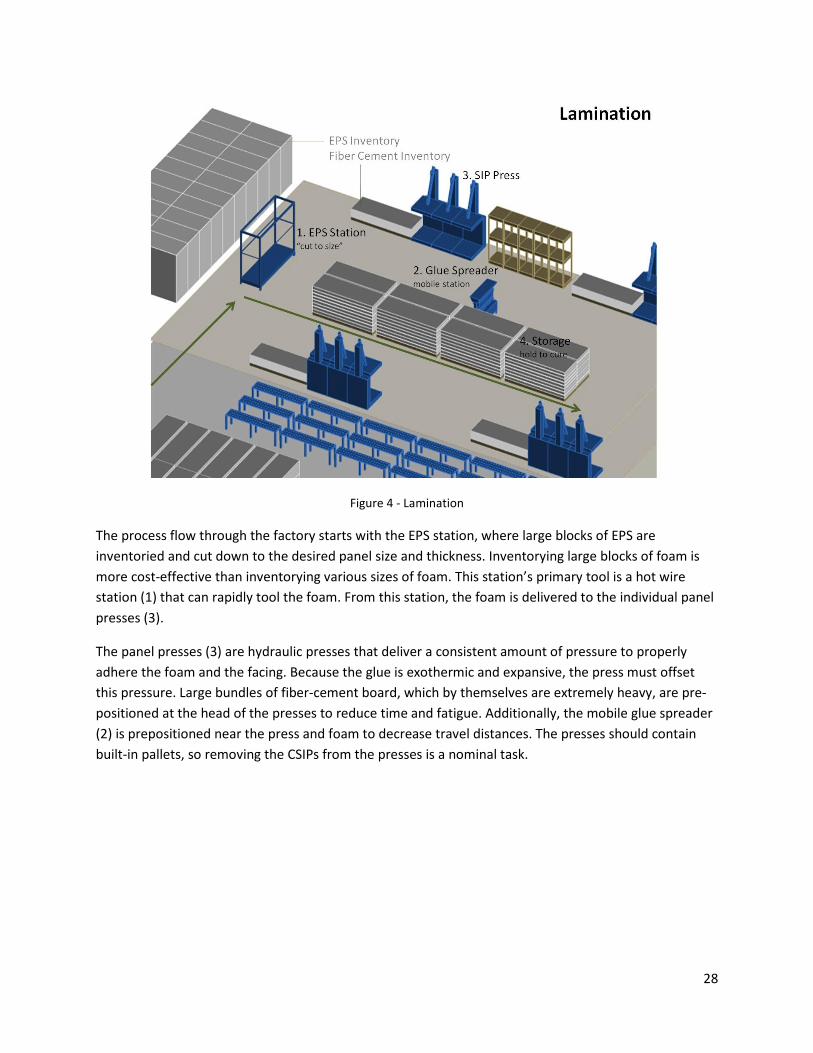
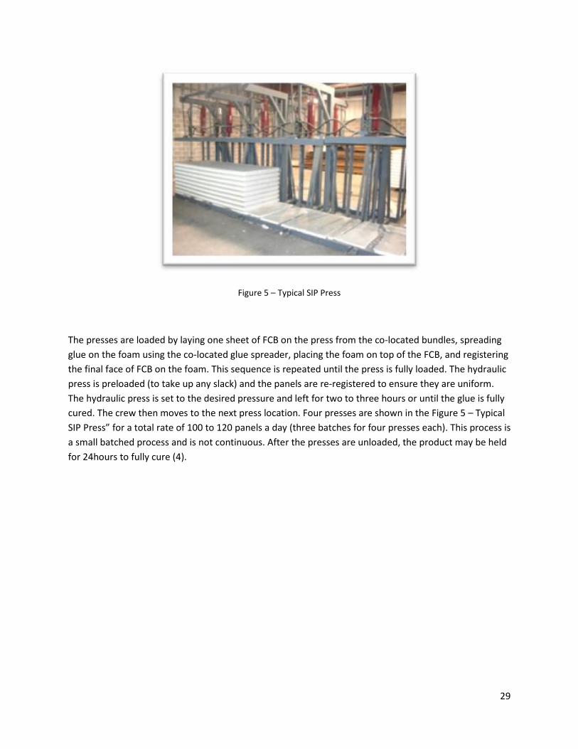
Figure 5 – Typical SIP Press
The presses are loaded by laying one sheet of FCB on the press from the co-located bundles, spreading
glue on the foam using the co-located glue spreader, placing the foam on top of the FCB, and registering
the final face of FCB on the foam. This sequence is repeated until the press is fully loaded. The hydraulic
press is preloaded (to take up any slack) and the panels are re-registered to ensure they are uniform.
The hydraulic press is set to the desired pressure and left for two to three hours or until the glue is fully
cured. The crew then moves to the next press location. Four presses are shown in the Figure 5 – Typical
SIP Press” for a total rate of 100 to 120 panels a day (three batches for four presses each). This process is
a small batched process and is not continuous. After the presses are unloaded, the product may be held
for 24hours to fully cure (4).
30
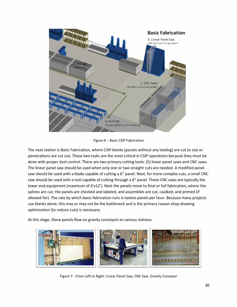
Figure 6 – Basic CSIP Fabrication
The next station is Basic Fabrication, where CSIP blanks (panels without any tooling) are cut to size or
penetrations are cut out. These two tasks are the most critical in CSIP operations because they must be
done with proper dust control. There are two primary cutting tools: (5) linear panel saws and CNC saws.
The linear panel saw should be used when only one or two straight cuts are needed. A modified panel
saw should be used with a blade capable of cutting a 6” panel. Next, for more complex cuts, a small CNC
saw should be used with a tool capable of cutting through a 6” panel. These CNC saws are typically the
lower end equipment (maximum of 4’x12’). Next the panels move to final or full fabrication, where the
splines are cut, the panels are checked and labeled, and assemblies are cut, caulked, and primed (if
allowed for). The rate by which basic fabrication runs is twelve panels per hour. Because many projects
use blanks alone, this may or may not be the bottleneck and is the primary reason shop drawing
optimization (to reduce cuts) is necessary.
At this stage, these panels flow on gravity conveyors to various stations.
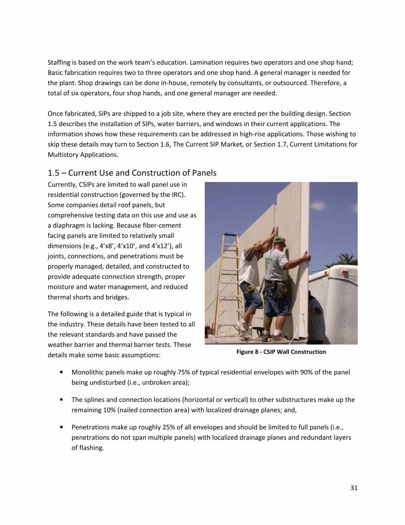
Figure 7 - From Left to Right: Linear Panel Saw, CNC Saw, Gravity Conveyor
31
Staffing is based on the work team’s education. Lamination requires two operators and one shop hand;
Basic fabrication requires two to three operators and one shop hand. A general manager is needed for
the plant. Shop drawings can be done in-house, remotely by consultants, or outsourced. Therefore, a
total of six operators, four shop hands, and one general manager are needed.
Once fabricated, SIPs are shipped to a job site, where they are erected per the building design. Section
1.5 describes the installation of SIPs, water barriers, and windows in their current applications. The
information shows how these requirements can be addressed in high-rise applications. Those wishing to
skip these details may turn to Section 1.6, The Current SIP Market, or Section 1.7, Current Limitations for
Multistory Applications.
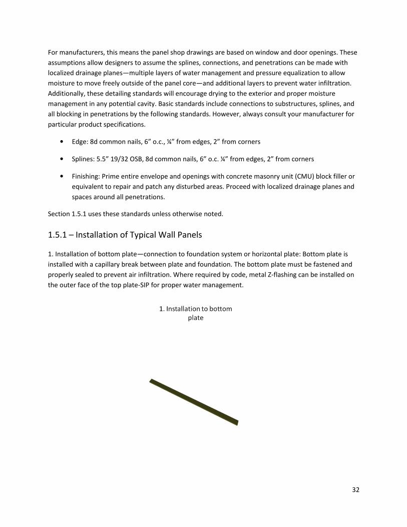
1.5 – Current Use and Construction of Panels
Currently, CSIPs are limited to wall panel use in
residential construction (governed by the IRC).
Some companies detail roof panels, but
comprehensive testing data on this use and use as
a diaphragm is lacking. Because fiber-cement
facing panels are limited to relatively small
dimensions (e.g., 4’x8’, 4’x10’, and 4’x12’), all
joints, connections, and penetrations must be
properly managed, detailed, and constructed to
provide adequate connection strength, proper
moisture and water management, and reduced
thermal shorts and bridges.
The following is a detailed guide that is typical in
the industry. These details have been tested to all
the relevant standards and have passed the
weather barrier and thermal barrier tests. These
details make some basic assumptions:
• Monolithic panels make up roughly 75% of typical residential envelopes with 90% of the panel
being undisturbed (i.e., unbroken area);
• The splines and connection locations (horizontal or vertical) to other substructures make up the
remaining 10% (nailed connection area) with localized drainage planes; and,
• Penetrations make up roughly 25% of all envelopes and should be limited to full panels (i.e.,
penetrations do not span multiple panels) with localized drainage planes and redundant layers
of flashing.
Figure 8 - CSIP Wall Construction
32
For manufacturers, this means the panel shop drawings are based on window and door openings. These
assumptions allow designers to assume the splines, connections, and penetrations can be made with
localized drainage planes—multiple layers of water management and pressure equalization to allow
moisture to move freely outside of the panel core—and additional layers to prevent water infiltration.
Additionally, these detailing standards will encourage drying to the exterior and proper moisture
management in any potential cavity. Basic standards include connections to substructures, splines, and
all blocking in penetrations by the following standards. However, always consult your manufacturer for
particular product specifications.
• Edge: 8d common nails, 6” o.c., ¼” from edges, 2” from corners
• Splines: 5.5” 19/32 OSB, 8d common nails, 6” o.c. ¼” from edges, 2” from corners
• Finishing: Prime entire envelope and openings with concrete masonry unit (CMU) block filler or
equivalent to repair and patch any disturbed areas. Proceed with localized drainage planes and
spaces around all penetrations.
Section 1.5.1 uses these standards unless otherwise noted.
1.5.1 – Installation of Typical Wall Panels
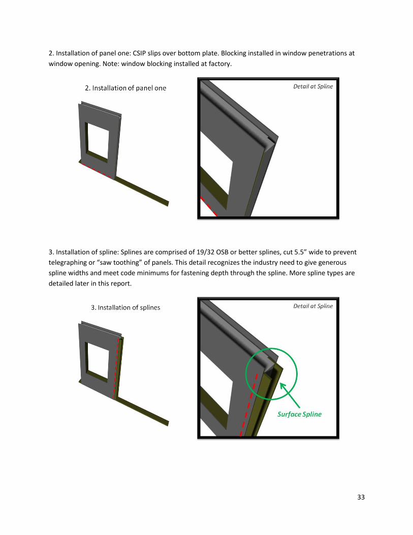
1. Installation of bottom plate—connection to foundation system or horizontal plate: Bottom plate is
installed with a capillary break between plate and foundation. The bottom plate must be fastened and
properly sealed to prevent air infiltration. Where required by code, metal Z-flashing can be installed on
the outer face of the top plate-SIP for proper water management.
33
2. Installation of panel one: CSIP slips over bottom plate. Blocking installed in window penetrations at
window opening. Note: window blocking installed at factory.
3. Installation of spline: Splines are comprised of 19/32 OSB or better splines, cut 5.5” wide to prevent
telegraphing or “saw toothing” of panels. This detail recognizes the industry need to give generous
spline widths and meet code minimums for fastening depth through the spline. More spline types are
detailed later in this report.
34
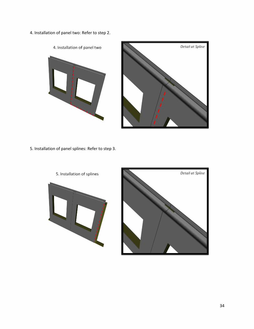
4. Installation of panel two: Refer to step 2.
5. Installation of panel splines: Refer to step 3.
35
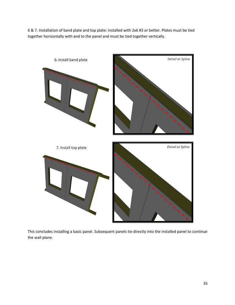
6 & 7. Installation of band plate and top plate: installed with 2x6 #3 or better. Plates must be tied
together horizontally with and to the panel and must be tied together vertically.
This concludes installing a basic panel. Subsequent panels tie directly into the installed panel to continue
the wall plane.
36
1.5.2 – Construction of Weather Barrier and Window/Other Penetrations
The construction of the weather barrier follows. These details are shown both as an individual panel and
as two combined panels.
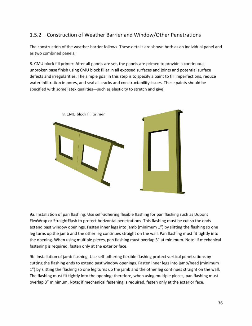
8. CMU block fill primer: After all panels are set, the panels are primed to provide a continuous
unbroken base finish using CMU block filler in all exposed surfaces and joints and potential surface
defects and irregularities. The simple goal in this step is to specify a paint to fill imperfections, reduce
water infiltration in pores, and seal all cracks and constructability issues. These paints should be
specified with some latex qualities—such as elasticity to stretch and give.
9a. Installation of pan flashing: Use self-adhering flexible flashing for pan flashing such as Dupont
FlexWrap or StraightFlash to protect horizontal penetrations. This flashing must be cut so the ends
extend past window openings. Fasten inner legs into jamb (minimum 1”) by slitting the flashing so one
leg turns up the jamb and the other leg continues straight on the wall. Pan flashing must fit tightly into
the opening. When using multiple pieces, pan flashing must overlap 3” at minimum. Note: if mechanical
fastening is required, fasten only at the exterior face.
9b. Installation of jamb flashing: Use self-adhering flexible flashing protect vertical penetrations by
cutting the flashing ends to extend past window openings. Fasten inner legs into jamb/head (minimum
1”) by slitting the flashing so one leg turns up the jamb and the other leg continues straight on the wall.
The flashing must fit tightly into the opening; therefore, when using multiple pieces, pan flashing must
overlap 3” minimum. Note: if mechanical fastening is required, fasten only at the exterior face.
37
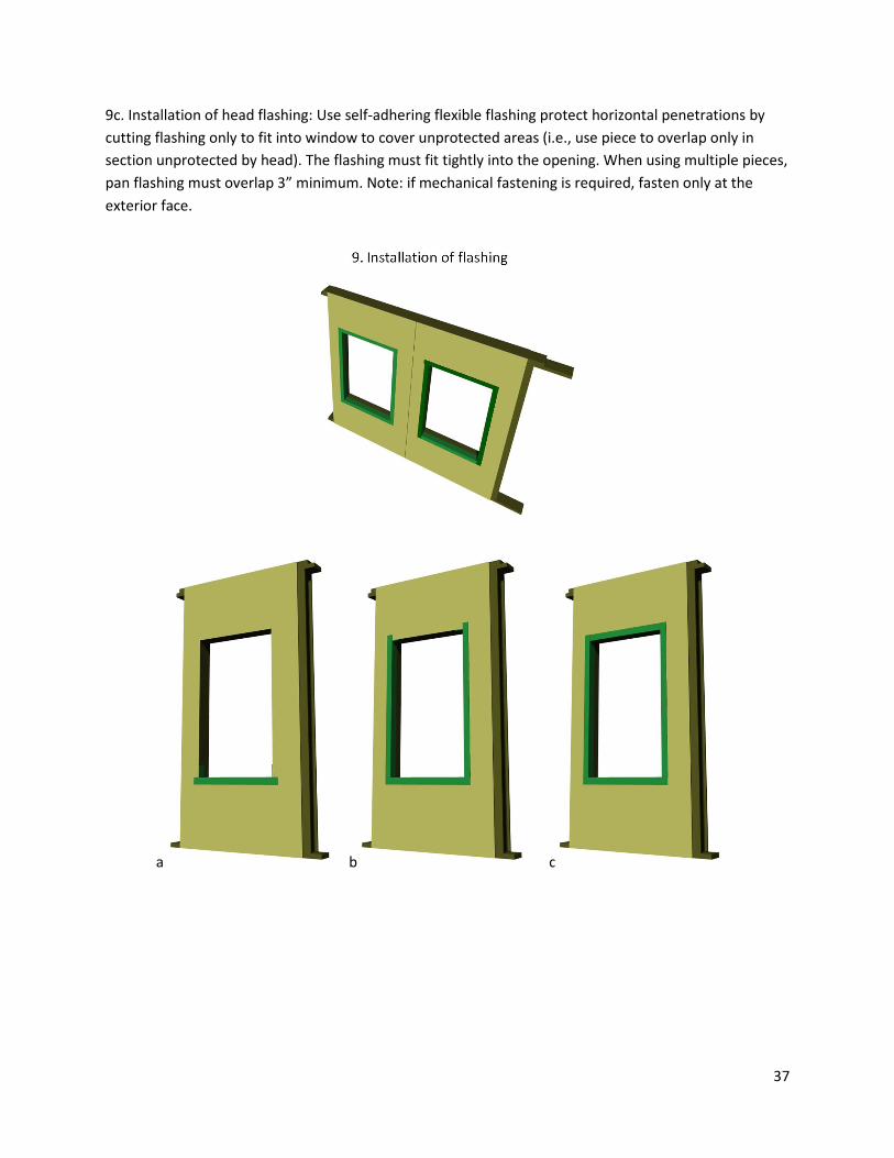
9c. Installation of head flashing: Use self-adhering flexible flashing protect horizontal penetrations by
cutting flashing only to fit into window to cover unprotected areas (i.e., use piece to overlap only in
section unprotected by head). The flashing must fit tightly into the opening. When using multiple pieces,
pan flashing must overlap 3” minimum. Note: if mechanical fastening is required, fasten only at the
exterior face.
a b c
38
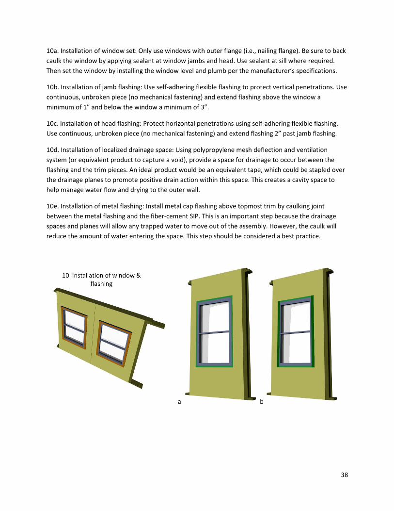
10a. Installation of window set: Only use windows with outer flange (i.e., nailing flange). Be sure to back
caulk the window by applying sealant at window jambs and head. Use sealant at sill where required.
Then set the window by installing the window level and plumb per the manufacturer’s specifications.
10b. Installation of jamb flashing: Use self-adhering flexible flashing to protect vertical penetrations. Use
continuous, unbroken piece (no mechanical fastening) and extend flashing above the window a
minimum of 1” and below the window a minimum of 3”.
10c. Installation of head flashing: Protect horizontal penetrations using self-adhering flexible flashing.
Use continuous, unbroken piece (no mechanical fastening) and extend flashing 2” past jamb flashing.
10d. Installation of localized drainage space: Using polypropylene mesh deflection and ventilation
system (or equivalent product to capture a void), provide a space for drainage to occur between the
flashing and the trim pieces. An ideal product would be an equivalent tape, which could be stapled over
the drainage planes to promote positive drain action within this space. This creates a cavity space to
help manage water flow and drying to the outer wall.
10e. Installation of metal flashing: Install metal cap flashing above topmost trim by caulking joint
between the metal flashing and the fiber-cement SIP. This is an important step because the drainage
spaces and planes will allow any trapped water to move out of the assembly. However, the caulk will
reduce the amount of water entering the space. This step should be considered a best practice.
a b
39
c d e
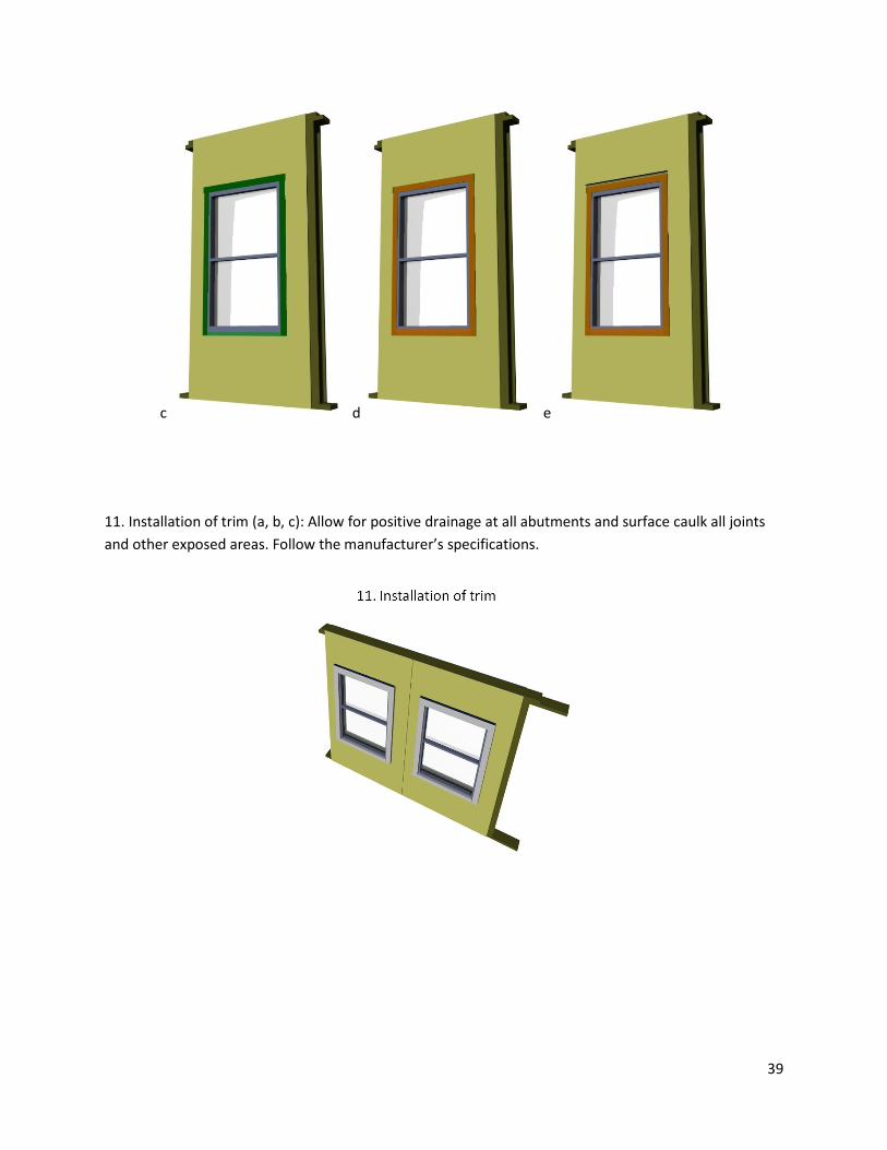
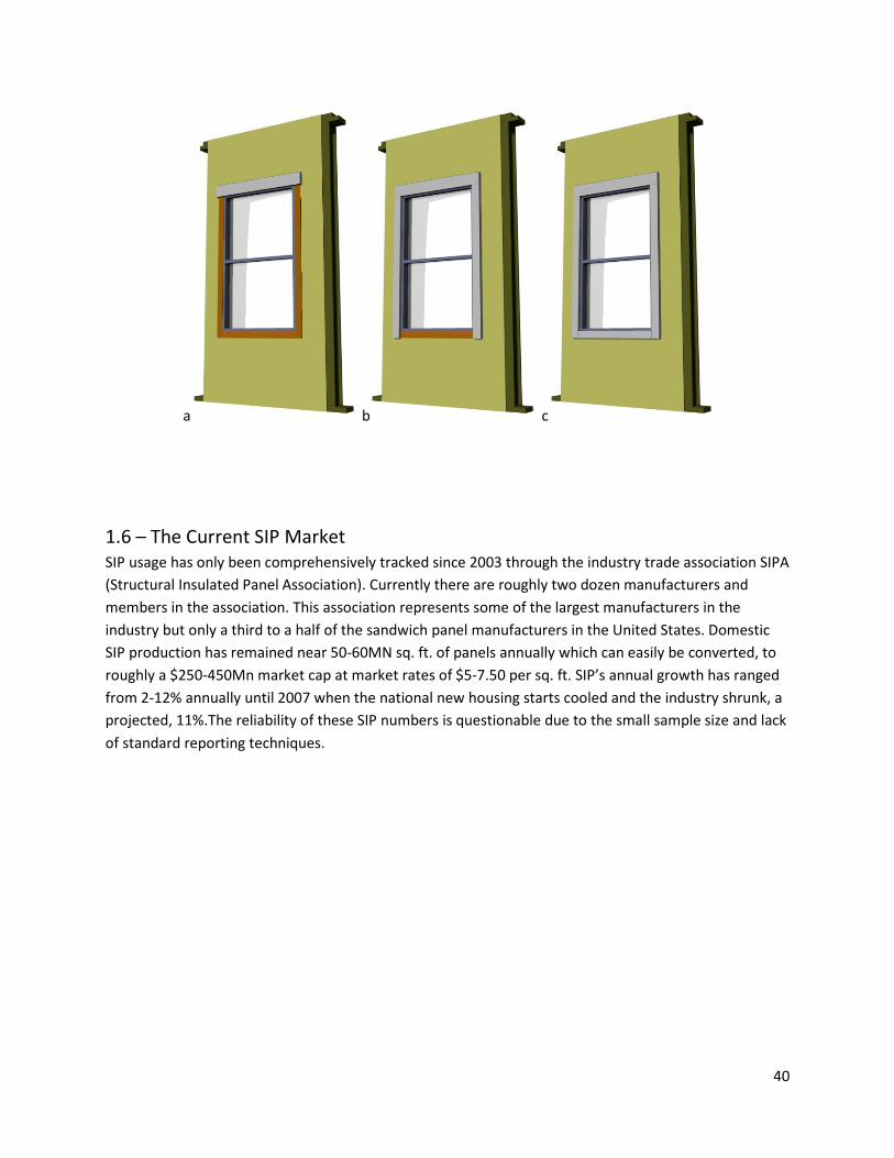
11. Installation of trim (a, b, c): Allow for positive drainage at all abutments and surface caulk all joints
and other exposed areas. Follow the manufacturer’s specifications.
40
a b c
1.6 – The Current SIP Market
SIP usage has only been comprehensively tracked since 2003 through the industry trade association SIPA
(Structural Insulated Panel Association). Currently there are roughly two dozen manufacturers and
members in the association. This association represents some of the largest manufacturers in the
industry but only a third to a half of the sandwich panel manufacturers in the United States. Domestic
SIP production has remained near 50-60MN sq. ft. of panels annually which can easily be converted, to
roughly a $250-450Mn market cap at market rates of $5-7.50 per sq. ft. SIP’s annual growth has ranged
from 2-12% annually until 2007 when the national new housing starts cooled and the industry shrunk, a
projected, 11%.The reliability of these SIP numbers is questionable due to the small sample size and lack
of standard reporting techniques.
41
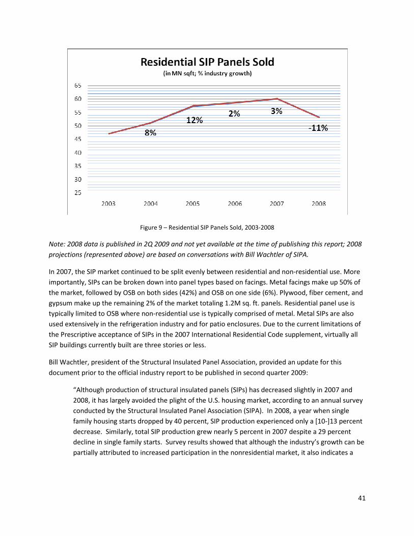
Figure 9 – Residential SIP Panels Sold, 2003-2008
Note: 2008 data is published in 2Q 2009 and not yet available at the time of publishing this report; 2008
projections (represented above) are based on conversations with Bill Wachtler of SIPA.
In 2007, the SIP market continued to be split evenly between residential and non-residential use. More
importantly, SIPs can be broken down into panel types based on facings. Metal facings make up 50% of
the market, followed by OSB on both sides (42%) and OSB on one side (6%). Plywood, fiber cement, and
gypsum make up the remaining 2% of the market totaling 1.2M sq. ft. panels. Residential panel use is
typically limited to OSB where non-residential use is typically comprised of metal. Metal SIPs are also
used extensively in the refrigeration industry and for patio enclosures. Due to the current limitations of
the Prescriptive acceptance of SIPs in the 2007 International Residential Code supplement, virtually all
SIP buildings currently built are three stories or less.
Bill Wachtler, president of the Structural Insulated Panel Association, provided an update for this
document prior to the official industry report to be published in second quarter 2009:
“Although production of structural insulated panels (SIPs) has decreased slightly in 2007 and
2008, it has largely avoided the plight of the U.S. housing market, according to an annual survey
conducted by the Structural Insulated Panel Association (SIPA). In 2008, a year when single
family housing starts dropped by 40 percent, SIP production experienced only a [10-]13 percent
decrease. Similarly, total SIP production grew nearly 5 percent in 2007 despite a 29 percent
decline in single family starts. Survey results showed that although the industry’s growth can be
partially attributed to increased participation in the nonresidential market, it also indicates a
42
sizable gain in residential market share [projected to have increased from 0.75% of all new
housing starts to 1.0% of all new housing starts].”11
1.6.1 – Market Growth Potential
The CSIP (and larger SIP) industry currently faces many obstacles to growth, but it carries significant
potential for expansion within current and new markets.
The major current problem is a significant lack of awareness and technical knowledge from owners,
builders, architects, engineers, and the general public. If these key members in the construction process
aren’t aware of CSIPs, they will not specify their use. This problem is compounded by a shortage of case
histories and case studies, a lack of standardization and specifications within the industry, and a lack of
knowledgeable installers, as well as the diverse base of small manufacturers. In addition, fire resistance
performance and building codes limit large-scale growth. These issues are addressed in Sections 1.7,
2.2.8, 3.5, and 4.2.
Like any new building system, a builder’s first SIP construction project is likely to have problems.
However, SIP construction has a fast learning curve, and we must avoid the perception that SIPs are
difficult to install.
In addition, CSIPs face the need for industry development. Since the industry is small, production
capacity is limited and slow to respond to market opportunities. Also, the CSIP supply chain is in its
infancy and has only limited distribution channels and lacks a strong, national brand name. Growth
depends on finding more CSIP manufacturer start-ups to generate demand for the product, rather than
waiting for the OSB-faced SIP industry to recognize the new market value of CSIPs and expand to include
the new material in production lines. The potential for product failure due to a lack of technical
background, a lack of continued service after sale, and a concern that a poor quality product could ruin
the SIP industry’s reputation are other potential problems for such a young industry.
Finally, testing, national standards, and inconsistencies in manufacturing facilities slow the industry’s
growth. CSIP needs industry partnerships to leverage applications testing, including producing more
data on the panels’ seismic, moisture, durability, and weatherization. This testing must also work toward
informing a standardized process for manufacturing and acceptance. CSIP manufacturers must develop
and conform to consensus-based reference standards (ANSI). This formal development of processes and
standards is important for a certified CSIP to spread and pick up new manufacturing locations.
Despite these obstacles, SIPs are gaining market share within the construction industry, which is good
and bad for CSIPs. Within the SIP industry, the overwhelming trend is to use OSB facings, so the
technical approach is focused on one facing material. Even so, this use is also spreading an awareness of
SIPs as a building technology independent of facing materials, making the recognition of and transition
to cement-fiber facings easier.
11
Email correspondence and conversations between Joe Hagerman and Bill Wachtler of SIPA.
43
For CSIPs to become a recognized substitute to SIPs, it requires code recognition and the removal of
building size limitations. In addition, CSIPs must work for inclusion in the SIP Prescriptive Method for the
IRC, and must work to extend a similar prescriptive method accepted into the International Building
Code (IBC). Without being accepted directly into the code, every CSIP project will require engineering to
show compliance. Overcoming this step will make it much easier for builders to choose CSIPs for their
building projects.
Despite these obstacles, SIPs offer many qualities that are becoming increasingly desirable, and there is
tremendous opportunity for CSIPs in current and new construction markets. This opportunity is largely
driven by rapidly increasing energy and construction costs, and the ever-growing interest in “green”
building. Due to their inherent energy-efficient performance and ease of construction, CSIPs are an
attractive candidate for addressing these variables. When paired with other energy-efficient and green
technologies, CSIPs favorably affect a building owner’s return on investment, asset turnover,
opportunity cost, and environmentalism.
SIPs’ composite nature makes them versatile and desirable for both single- and multistory construction.
For both building types, CSIPs are an enabling technology that reduce substructure demands. CSIPs also
offer an easily constructed, thermally efficient, cost-effective alternative building envelope. The wealth
of materials and design options available allows considerable flexibility for new designs and uses.
In sum, CSIPs require significant development to fully embrace their potential. This report systematically
compiles data based on the current CSIP industry and includes a detailed description of its potential
extensions and future development.
1.7 – Current Limitations for Multistory Application
Two major factors currently limit the application of CSIPs to multistory construction: building codes and CSIP
performance. Building code limitations will be explained here, while the latter will be discussed in-depth in
Section 2.
Currently, CSIPs are used in construction up to three stories. This report uses the term “multistory” to focus
on buildings above this threshold. While the applicable building code for a project is determined by the
municipality providing the building permit, the majority of municipalities have adopted the I-Codes, a set of
codes created by the ICC. The ICC has created distinct codes for one- and two-story residential construction
(IRC), larger commercial and industrial construction (IBC), energy conservation in buildings (IECC), and more.
For multistory construction, the IBC is the most widely adopted code and will govern the majority of the
buildings within the scope of this report.
Despite this baseline, local codes dictate the decisions and understanding of acceptable CSIP applications.
The basis for panels used in multistory construction is restricted by the following:
• Combustibility (discussed in Section 2.2.8.1) based on ASTM E136 - 04 Standard Test Method for
Behavior of Materials in a Vertical Tube Furnace at 750°C and ISO 1182 Non-Combustibility Test
for Building Materials limit CSIPs to:
44
o Type V construction (three story maximum per Table 503 ); limitations dictated by the
building code in Chapter 6, Types of Construction, and Chapter 5, General Building
Heights and Areas, and
o Exterior wall coverings in Type I buildings per 603.1.10.
• Fire Rating (discussed in Section 2.2.8.2) based on ASTM E119 - 08a Standard Test Methods for
Fire Tests of Building Construction require CSIPs to conform to IBC 2603.4 Thermal Barrier. Note:
each vendor must show compliance as a thermal barrier.
• Weather Barrier based on ASTM E331-00 Standard Test Method for Water Penetration of
Exterior Windows, Skylights, Doors, and Curtain Walls by Uniform Static Air Pressure Difference
require CSIPs to:
o Conform to IBC 1403.2 as a weather barrier resistant to water intrusion and vapor
permeance to allow drying while reducing vapor intrusion.
o Weather barriers are manufacturer/vendor specific. Typical details shown in Section
1.5.3 have been known to pass the weather barrier requirements, but each
manufacturer/vendor must show compliance as a weather barrier.
• Fiber-Cement Siding under IBC 1405.15 Fiber-Cement Siding as a Metal Veneer assembly
(requiring the same fasteners, finishes, and other performance requirements of Metal Veneer
assemblies.
The ways panels can be used in multistory construction are further limited by the following code
provisions:
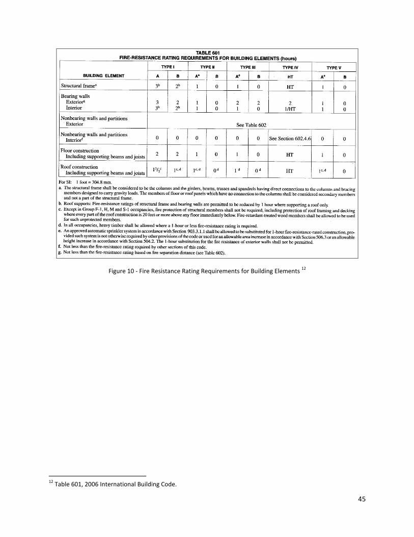
• Required fire ratings, Table 601 (discussed in 2.2.8)
o CSIPs must obtain a fire separation distance greater than or equally to 30’ (per Table
602) for exterior walls.
o Joints in exterior walls are not required to have a fire rating (per 704.13).
45
Figure 10 - Fire Resistance Rating Requirements for Building Elements 12
12
Table 601, 2006 International Building Code.
46
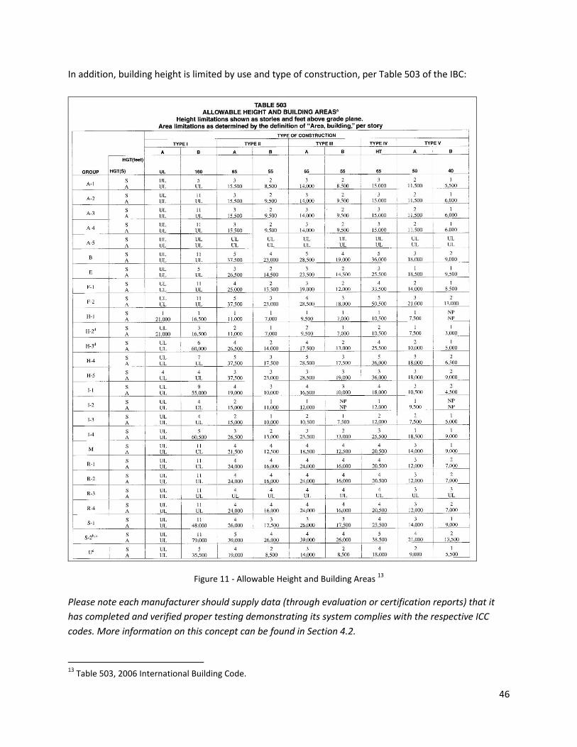
In addition, building height is limited by use and type of construction, per Table 503 of the IBC:
Figure 11 - Allowable Height and Building Areas 13
Please note each manufacturer should supply data (through evaluation or certification reports) that it
has completed and verified proper testing demonstrating its system complies with the respective ICC
codes. More information on this concept can be found in Section 4.2.
13
Table 503, 2006 International Building Code.