1 (a) ans. (b) ans. fa = 34.9 kn + c ©f y = 0; fa - 4.5 - 4.5 - 5.89 - 6
TRANSCRIPT

1
(a)
Ans.
(b)
Ans. FA = 34.9 kN
+ c ©Fy = 0; FA - 4.5 - 4.5 - 5.89 - 6 - 6 - 8 = 0
FA = 13.8 kip
+ c ©Fy = 0; FA - 1.0 - 3 - 3 - 1.8 - 5 = 0
1–1. Determine the resultant internal normal force actingon the cross section through point A in each column. In(a), segment BC weighs 180 >ft and segment CD weighs250 >ft. In (b), the column has a mass of 200 >m.kglb
lb
© 2010 Pearson Education, Inc., Upper Saddle River, NJ. All rights reserved. This material is protected under all copyright laws as they currentlyexist. No portion of this material may be reproduced, in any form or by any means, without permission in writing from the publisher.
8 kN
3 m
1 m
6 kN6 kN
4.5 kN4.5 kN
200 mm200 mm
A
(b)
200 mm200 mm3 kip3 kip
5 kip
10 ft
4 ft
4 ft
8 in.8 in.
A
C
D
(a)
B
1–2. Determine the resultant internal torque acting on thecross sections through points C and D.The support bearingsat A and B allow free turning of the shaft.
Ans.
Ans.©Mx = 0; TD = 0
TC = 250 N # m
©Mx = 0; TC - 250 = 0
A
BD
C300 mm
200 mm
150 mm200 mm
250 mm
150 mm
400 N�m
150 N�m
250 N�m
Ans.
Ans. TC = 500 lb # ft
©Mx = 0; TC - 500 = 0
TB = 150 lb # ft
©Mx = 0; TB + 350 - 500 = 0
1–3. Determine the resultant internal torque acting on thecross sections through points B and C.
3 ft
2 ft
2 ft
1 ft
B
A
C
500 lb�ft
350 lb�ft
600 lb�ft
01 Solutions 46060 5/6/10 2:43 PM Page 1

2
© 2010 Pearson Education, Inc., Upper Saddle River, NJ. All rights reserved. This material is protected under all copyright laws as they currentlyexist. No portion of this material may be reproduced, in any form or by any means, without permission in writing from the publisher.
*1–4. A force of 80 N is supported by the bracket asshown. Determine the resultant internal loadings acting onthe section through point A.
Equations of Equilibrium:
Ans.
Ans.
a
Ans.
or
a
Ans.
Negative sign indicates that MA acts in the opposite direction to that shown on FBD.
MA = -0.555 N # m
-80 cos 15°(0.1 cos 30°) = 0
+ ©MA = 0; MA + 80 sin 15°(0.3 + 0.1 sin 30°)
MA = -0.555 N # m
- 80 sin 45°(0.1 + 0.3 sin 30°) = 0
+ ©MA = 0; MA + 80 cos 45°(0.3 cos 30°)
VA = 20.7 N
a+ ©Fy¿= 0; VA - 80 sin 15° = 0
NA = 77.3 N
+Q©Fx¿= 0; NA - 80 cos 15° = 0
0.1 m
0.3 m
30�
80 N
A
45�
01 Solutions 46060 5/6/10 2:43 PM Page 2

3
Support Reactions: For member AB
a
Equations of Equilibrium: For point D
Ans.
Ans.
a
Ans.
Equations of Equilibrium: For point E
Ans.
Ans.
a
Ans.
Negative signs indicate that ME and VE act in the opposite direction to that shownon FBD.
ME = -24.0 kip # ft
+ ©ME = 0; ME + 6.00(4) = 0
VE = -9.00 kip
+ c ©Fy = 0; -6.00 - 3 - VE = 0
:+ ©Fx = 0; NE = 0
MD = 13.5 kip # ft
+ ©MD = 0; MD + 2.25(2) - 3.00(6) = 0
VD = 0.750 kip
+ c ©Fy = 0; 3.00 - 2.25 - VD = 0
:+ ©Fx = 0; ND = 0
+ c ©Fy = 0; By + 3.00 - 9.00 = 0 By = 6.00 kip
:+ ©Fx = 0; Bx = 0
+ ©MB = 0; 9.00(4) - Ay(12) = 0 Ay = 3.00 kip
•1–5. Determine the resultant internal loadings in thebeam at cross sections through points D and E. Point E isjust to the right of the 3-kip load.
© 2010 Pearson Education, Inc., Upper Saddle River, NJ. All rights reserved. This material is protected under all copyright laws as they currentlyexist. No portion of this material may be reproduced, in any form or by any means, without permission in writing from the publisher.
6 ft 4 ft
A
4 ft
B CD E
6 ft
3 kip
1.5 kip/ ft
01 Solutions 46060 5/6/10 2:43 PM Page 3

4
Support Reactions:
a
Equations of Equilibrium: For point C
Ans.
Ans.
a
Ans.
Negative signs indicate that NC and VC act in the opposite direction to that shownon FBD.
MC = 6.00 kN # m
+ ©MC = 0; 8.00(0.75) - MC = 0
VC = -8.00 kN
+ c ©Fy = 0; VC + 8.00 = 0
NC = -30.0 kN
:+ ©Fx = 0; -NC - 30.0 = 0
+ c ©Fy = 0; Ay - 8 = 0 Ay = 8.00 kN
:+ ©Fx = 0; 30.0 - Ax = 0 Ax = 30.0 kN
+ ©MA = 0; 8(2.25) - T(0.6) = 0 T = 30.0 kN
1–6. Determine the normal force, shear force, and momentat a section through point C. Take P = 8 kN.
© 2010 Pearson Education, Inc., Upper Saddle River, NJ. All rights reserved. This material is protected under all copyright laws as they currentlyexist. No portion of this material may be reproduced, in any form or by any means, without permission in writing from the publisher.
0.75 m
C
P
A
B
0.5 m0.1 m
0.75 m 0.75 m
Support Reactions:
a
Ans.
Equations of Equilibrium: For point C
Ans.
Ans.
a
Ans.
Negative signs indicate that NC and VC act in the opposite direction to that shownon FBD.
MC = 0.400 kN # m
+ ©MC = 0; 0.5333(0.75) - MC = 0
VC = -0.533 kN
+ c ©Fy = 0; VC + 0.5333 = 0
NC = -2.00 kN
:+ ©Fx = 0; -NC - 2.00 = 0
+ c ©Fy = 0; Ay - 0.5333 = 0 Ay = 0.5333 kN
:+ ©Fx = 0; 2 - Ax = 0 Ax = 2.00 kN
P = 0.5333 kN = 0.533 kN
+ ©MA = 0; P(2.25) - 2(0.6) = 0
1–7. The cable will fail when subjected to a tension of 2 kN.Determine the largest vertical load P the frame will supportand calculate the internal normal force, shear force, andmoment at the cross section through point C for this loading.
0.75 m
C
P
A
B
0.5 m0.1 m
0.75 m 0.75 m
01 Solutions 46060 5/6/10 2:43 PM Page 4

5
© 2010 Pearson Education, Inc., Upper Saddle River, NJ. All rights reserved. This material is protected under all copyright laws as they currentlyexist. No portion of this material may be reproduced, in any form or by any means, without permission in writing from the publisher.
Referring to the FBD of the entire beam, Fig. a,
a
Referring to the FBD of this segment, Fig. b,
Ans.
Ans.
a Ans.+ ©MC = 0; MC + 6(0.5) - 7.5(1) = 0 MC = 4.50 kN # m
+ c ©Fy = 0; 7.50 - 6 - VC = 0 VC = 1.50 kN
:+ ©Fx = 0; NC = 0
+ ©MB = 0; -Ay(4) + 6(3.5) +
12
(3)(3)(2) = 0 Ay = 7.50 kN
*1–8. Determine the resultant internal loadings on thecross section through point C. Assume the reactions atthe supports A and B are vertical.
0.5 m 0.5 m1.5 m1.5 m
CA B
3 kN/m6 kN
D
Referring to the FBD of the entire beam, Fig. a,
a
Referring to the FBD of this segment, Fig. b,
Ans.
Ans.
a
Ans. = 3.94 kN # m
+ ©MD = 0; 3.00(1.5) -
12
(1.5)(1.5)(0.5) - MD = 0 MD = 3.9375 kN # m
+ c ©Fy = 0; VD -
12
(1.5)(1.5) + 3.00 = 0 VD = -1.875 kN
:+ ©Fx = 0; ND = 0
+ ©MA = 0; By(4) - 6(0.5) -
12
(3)(3)(2) = 0 By = 3.00 kN
•1–9. Determine the resultant internal loadings on thecross section through point D. Assume the reactions atthe supports A and B are vertical.
0.5 m 0.5 m1.5 m1.5 m
CA B
3 kN/m6 kN
D
01 Solutions 46060 5/6/10 2:43 PM Page 5

6
© 2010 Pearson Education, Inc., Upper Saddle River, NJ. All rights reserved. This material is protected under all copyright laws as they currentlyexist. No portion of this material may be reproduced, in any form or by any means, without permission in writing from the publisher.
Equations of Equilibrium: For point A
Ans.
Ans.
a
Ans.
Negative sign indicates that MA acts in the opposite direction to that shown on FBD.
Equations of Equilibrium: For point B
Ans.
Ans.
a
Ans.
Negative sign indicates that MB acts in the opposite direction to that shown on FBD.
Equations of Equilibrium: For point C
Ans.
Ans.
a
Ans.
Negative signs indicate that NC and MC act in the opposite direction to that shownon FBD.
MC = -8125 lb # ft = -8.125 kip # ft
+ ©MC = 0; -MC - 650(6.5) - 300(13) = 0
NC = -1200 lb = -1.20 kip
+ c © Fy = 0; -NC - 250 - 650 - 300 = 0
;+ © Fx = 0; VC = 0
MB = -6325 lb # ft = -6.325 kip # ft
+ © MB = 0; -MB - 550(5.5) - 300(11) = 0
VB = 850 lb
+ c © Fy = 0; VB - 550 - 300 = 0
;+ © Fx = 0; NB = 0
MA = -1125 lb # ft = -1.125 kip # ft
+ ©MA = 0; -MA - 150(1.5) - 300(3) = 0
VA = 450 lb
+ c © Fy = 0; VA - 150 - 300 = 0
;+ © Fx = 0; NA = 0
1–10. The boom DF of the jib crane and the column DEhave a uniform weight of 50 lb/ft. If the hoist and load weigh300 lb, determine the resultant internal loadings in the craneon cross sections through points A, B, and C. 5 ft
7 ft
C
D F
E
B A
300 lb
2 ft 8 ft 3 ft
01 Solutions 46060 5/6/10 2:43 PM Page 6

7
© 2010 Pearson Education, Inc., Upper Saddle River, NJ. All rights reserved. This material is protected under all copyright laws as they currentlyexist. No portion of this material may be reproduced, in any form or by any means, without permission in writing from the publisher.
Equations of Equilibrium: For section a–a
Ans.
Ans.
a
Ans. MA = 14.5 lb # in.
+ ©MA = 0; -MA - 80 sin 15°(0.16) + 80 cos 15°(0.23) = 0
NA = 20.7 lb
a+ ©Fy¿= 0; NA - 80 sin 15° = 0
VA = 77.3 lb
+Q©Fx¿= 0; VA - 80 cos 15° = 0
1–11. The force acts on the gear tooth.Determine the resultant internal loadings on the root of thetooth, i.e., at the centroid point A of section a–a.
F = 80 lb a
30�
a
F � 80 lb
0.23 in.
45�
A
0.16 in.
Support Reactions:
Equations of Equilibrium: For point D
Ans.
Ans.
Ans.
Equations of Equilibrium: For point E
Ans.
Ans.
Ans. ME = 18.0 kN # m
d+ © ME = 0; 90.0(0.2) - ME = 0
+ c © Fy = 0; NE = 0
VE = 90.0 kN
:+ © Fx = 0; 90.0 - VE = 0
MD = 21.6 kN # m
d+ © MD = 0; MD + 18(0.3) - 90.0(0.3) = 0
ND = 18.0 kN
+ c © Fy = 0; ND - 18 = 0
VD = 90.0 kN
:+ © Fx = 0; VD - 90.0 = 0
:+ ©Fx = 0; NC - 90.0 = 0 NC = 90.0 kN
NA = 90.0 kN
d+ ©MC = 0; 18(0.7) - 18.0(0.2) - NA(0.1) = 0
+ c ©Fy = 0; NB - 18 = 0 NB = 18.0 kN
*1–12. The sky hook is used to support the cable of ascaffold over the side of a building. If it consists of a smoothrod that contacts the parapet of a wall at points A, B, and C,determine the normal force, shear force, and moment onthe cross section at points D and E.
0.2 m
0.2 m 0.2 m
0.2 m
0.2 m
0.3 m
0.3 m
18 kN
A
D E
B
C
01 Solutions 46060 5/6/10 2:43 PM Page 7

8
© 2010 Pearson Education, Inc., Upper Saddle River, NJ. All rights reserved. This material is protected under all copyright laws as they currentlyexist. No portion of this material may be reproduced, in any form or by any means, without permission in writing from the publisher.
•1–13. The 800-lb load is being hoisted at a constant speedusing the motor M, which has a weight of 90 lb. Determinethe resultant internal loadings acting on the cross sectionthrough point B in the beam. The beam has a weight of40 lb>ft and is fixed to the wall at A.
M
4 ft 3 ft 4 ft
C B
1.5 ftA
0.25 ft
4 ft 3 ft
D
1–14. Determine the resultant internal loadings acting onthe cross section through points C and D of the beam inProb. 1–13.
M
4 ft 3 ft 4 ft
C B
1.5 ftA
0.25 ft
4 ft 3 ft
D
Ans.
Ans.
a
Ans. MB = -3.12 kip # ft
+ ©MB = 0; - MB - 0.16(2) - 0.8(4.25) + 0.4(1.5) = 0
VB = 0.960 kip
+ c ©Fy = 0; VB - 0.8 - 0.16 = 0
NB = - 0.4 kip
:+ ©Fx = 0; - NB - 0.4 = 0
For point C:
Ans.
Ans.
a
Ans.
For point D:
Ans.
Ans.
a
Ans. MD = -15.7 kip # ft
+ ©MD = 0; - MD - 0.09(4) - 0.04(14)(7) - 0.8(14.25) = 0
+ c ©Fy = 0; VD - 0.09 - 0.04(14) - 0.8 = 0; VD = 1.45 kip
;+ ©Fx = 0; ND = 0
MC = -6.18 kip # ft
+ ©MC = 0; - MC - 0.8(7.25) - 0.04(7)(3.5) + 0.4(1.5) = 0
+ c ©Fy = 0; VC - 0.8 - 0.04 (7) = 0; VC = 1.08 kip
;+ ©Fx = 0; NC + 0.4 = 0; NC = - 0.4kip
01 Solutions 46060 5/6/10 2:43 PM Page 8

© 2010 Pearson Education, Inc., Upper Saddle River, NJ. All rights reserved. This material is protected under all copyright laws as they currentlyexist. No portion of this material may be reproduced, in any form or by any means, without permission in writing from the publisher.
1–15. Determine the resultant internal loading on thecross section through point C of the pliers. There is a pin atA, and the jaws at B are smooth.
120 mm 40 mm
15 mm
80 mm
A
C
D
30�
20 N
20 N
B
9
*1–16. Determine the resultant internal loading on thecross section through point D of the pliers. 120 mm 40 mm
15 mm
80 mm
A
C
D
30�
20 N
20 N
B
Ans.
Ans.
+d Ans.©MC = 0; -MC + 60(0.015) = 0; MC = 0.9 N.m
:+ ©Fx = 0; NC = 0
+ c ©Fy = 0; -VC + 60 = 0; VC = 60 N
Ans.
Ans.
+d Ans.©MD = 0; MD - 20(0.08) = 0; MD = 1.60 N.m
+b©Fx = 0; ND - 20 sin 30° = 0; ND = 10 N
R+ ©Fy = 0; VD - 20 cos 30° = 0; VD = 17.3 N
01 Solutions 46060 5/6/10 2:43 PM Page 9

10
© 2010 Pearson Education, Inc., Upper Saddle River, NJ. All rights reserved. This material is protected under all copyright laws as they currentlyexist. No portion of this material may be reproduced, in any form or by any means, without permission in writing from the publisher.
45�
1.5 m
1.5 m
3 m
45�
A
C
B
b a
ab
5 kN
Referring to the FBD of the entire beam, Fig. a,
a
Referring to the FBD of this segment (section a–a), Fig. b,
Ans.
Ans.
a Ans.
Referring to the FBD (section b–b) in Fig. c,
Ans.
Ans.
a
Ans.Mb - b = 3.75 kN # m
+ ©MC = 0; 5.303 sin 45° (3) - 5(1.5) - Mb - b = 0
+ c ©Fy = 0; Vb - b - 5 sin 45° = 0 Vb - b = 3.536 kN = 3.54 kN
= -1.77 kN
;+ ©Fx = 0; Nb - b - 5 cos 45° + 5.303 = 0 Nb - b = -1.768 kN
+ ©MC = 0; 5.303 sin 45°(3) - 5(1.5) - Ma - a = 0 Ma - a = 3.75 kN # m
+a ©Fy¿= 0; Va - a + 5.303 sin 45° - 5 = 0 Va - a = 1.25 kN
+b©Fx¿= 0; Na - a + 5.303 cos 45° = 0 Na - a = -3.75 kN
+ ©MA = 0; NB sin 45°(6) - 5(4.5) = 0 NB = 5.303 kN
•1–17. Determine resultant internal loadings acting onsection a–a and section b–b. Each section passes throughthe centerline at point C.
01 Solutions 46060 5/6/10 2:43 PM Page 10

11
© 2010 Pearson Education, Inc., Upper Saddle River, NJ. All rights reserved. This material is protected under all copyright laws as they currentlyexist. No portion of this material may be reproduced, in any form or by any means, without permission in writing from the publisher.
Segment AC:
Ans.
Ans.
a Ans.+ ©MC = 0; MC + 80(6) = 0; MC = -480 lb # in.
+ c ©Fy = 0; VC = 0
:+ ©Fx = 0; NC + 80 = 0; NC = -80 lb
1–18. The bolt shank is subjected to a tension of 80 lb.Determine the resultant internal loadings acting on thecross section at point C.
A B
C
90� 6 in.
Referring to the FBD of the entire beam, Fig. a,
a
Referring to the FBD of this segment, Fig. b,
Ans.
Ans.
a
Ans. MC = 31.5 kip # ft
+ ©MC = 0; MC + (3)(3)(1.5) +
12
(3)(3)(2) - 18.0(3) = 0
+ c ©Fy = 0; 18.0 -
12
(3)(3) - (3)(3) - VC = 0 VC = 4.50 kip
:+ ©Fx = 0; NC = 0
+ ©MB = 0; 12
(6)(6)(2) +
12
(6)(6)(10) - Ay(12) = 0 Ay = 18.0 kip
1–19. Determine the resultant internal loadings acting onthe cross section through point C. Assume the reactions atthe supports A and B are vertical.
3 ft 3 ft
DCA B
6 ft
6 kip/ft6 kip/ft
01 Solutions 46060 5/6/10 2:43 PM Page 11

12
© 2010 Pearson Education, Inc., Upper Saddle River, NJ. All rights reserved. This material is protected under all copyright laws as they currentlyexist. No portion of this material may be reproduced, in any form or by any means, without permission in writing from the publisher.
Referring to the FBD of the entire beam, Fig. a,
a
Referring to the FBD of this segment, Fig. b,
Ans.
Ans.
a Ans.+ ©MA = 0; MD - 18.0 (2) = 0 MD = 36.0 kip # ft
+ c ©Fy = 0; 18.0 -
12
(6)(6) - VD = 0 VD = 0
:+ ©Fx = 0; ND = 0
+ ©MB = 0; 12
(6)(6)(2) +
12
(6)(6)(10) - Ay(12) = 0 Ay = 18.0 kip
*1–20. Determine the resultant internal loadings actingon the cross section through point D. Assume the reactionsat the supports A and B are vertical.
3 ft 3 ft
DCA B
6 ft
6 kip/ft6 kip/ft
Internal Loadings: Referring to the free-body diagram of the section of the clampshown in Fig. a,
Ans.
Ans.
a Ans.+ ©MA = 0; 900(0.2) - Ma - a = 0 Ma - a = 180 N # m
©Fx¿= 0; Va - a - 900 sin 30° = 0 Va - a = 450 N
©Fy¿= 0; 900 cos 30° - Na - a = 0 Na - a = 779 N
•1–21. The forged steel clamp exerts a force of Non the wooden block. Determine the resultant internalloadings acting on section a–a passing through point A.
F = 900 200 mm
a
aF � 900 N
F � 900 N
30�A
01 Solutions 46060 5/6/10 2:43 PM Page 12

13
© 2010 Pearson Education, Inc., Upper Saddle River, NJ. All rights reserved. This material is protected under all copyright laws as they currentlyexist. No portion of this material may be reproduced, in any form or by any means, without permission in writing from the publisher.
Support Reactions: We will only need to compute FEF by writing the momentequation of equilibrium about D with reference to the free-body diagram of thehook, Fig. a.
a
Internal Loadings: Using the result for FEF, section FG of member EF will beconsidered. Referring to the free-body diagram, Fig. b,
Ans.
Ans.
a Ans.+ ©MG = 0; MG = 0
+ c ©Fy = 0; VG = 0
:+ ©Fx = 0; 9810 - NG = 0 NG = 9810 N = 9.81 kN
+ ©MD = 0; FEF(0.3) - 600(9.81)(0.5) = 0 FEF = 9810 N
1–22. The floor crane is used to lift a 600-kg concrete pipe.Determine the resultant internal loadings acting on thecross section at G.
0.2 m0.2 m
0.4 m
0.3 m
0.5 m
75�
0.6 m
C
A
E
B
F
DH
G
01 Solutions 46060 5/6/10 2:43 PM Page 13

14
© 2010 Pearson Education, Inc., Upper Saddle River, NJ. All rights reserved. This material is protected under all copyright laws as they currentlyexist. No portion of this material may be reproduced, in any form or by any means, without permission in writing from the publisher.
Support Reactions: Referring to the free-body diagram of the hook, Fig. a.
a
Subsequently, referring to the free-body diagram of member BCD, Fig. b,
a
Internal Loadings: Using the results of Bx and By, section BH of member BCD willbe considered. Referring to the free-body diagram of this part shown in Fig. c,
Ans.
Ans.
a
Ans.
The negative signs indicates that NH, VH, and MH act in the opposite sense to thatshown on the free-body diagram.
= -4.12 kN # m
+ ©MD = 0; MH + 20601(0.2) = 0 MH = -4120.2 N # m
+ c ©Fy = 0; -VH - 2060 = 0 VH = -20601 N = -20.6 kN
:+ ©Fx = 0; NH + 2712.83 = 0 NH = -2712.83 N = -2.71 kN
+ c ©Fy = 0; 27 421.36 sin 75° - 5886 - By = 0 By = 20 601 N
:+ ©Fx = 0; Bx + 27 421.36 cos 75° - 9810 = 0 Bx = 2712.83 N
+ ©MB = 0; FAC sin 75°(0.4) - 5886(1.8) = 0 FAC = 27 421.36 N
+ c ©Fy = 0; Dy - 600(9.81) = 0 Dy = 5886 N
+ ©MF = 0; Dx(0.3) - 600(9.81)(0.5) = 0 Dx = 9810 N
1–23. The floor crane is used to lift a 600-kg concrete pipe.Determine the resultant internal loadings acting on thecross section at H.
0.2 m0.2 m
0.4 m
0.3 m
0.5 m
75�
0.6 m
C
A
E
B
F
DH
G
01 Solutions 46060 5/6/10 2:43 PM Page 14

15
© 2010 Pearson Education, Inc., Upper Saddle River, NJ. All rights reserved. This material is protected under all copyright laws as they currentlyexist. No portion of this material may be reproduced, in any form or by any means, without permission in writing from the publisher.
Support Reactions: We will only need to compute NA by writing the momentequation of equilibrium about B with reference to the free-body diagram of thesteamroller, Fig. a.
a
Internal Loadings: Using the result for NA, the free-body diagram of the front rollershown in Fig. b will be considered.
Ans.
Ans.
a
Ans.= 4.46 kN # m
+ ©MC = 0; 53.51(103)(2) - 5(103)(9.81)(2) - 2MC = 0 MC = 4459.10 N # m
= -2.23 kN
+ c ©Fy = 0; 2VC + 53.51(103) - 5(103)(9.81) = 0 VC = -2229.55 N
;+ ©Fx = 0; 2NC = 0 NC = 0
+ ©MB = 0; NA (5.5) - 20(103)(9.81)(1.5) = 0 NA = 53.51(103) N
*1–24. The machine is moving with a constant velocity. Ithas a total mass of 20 Mg, and its center of mass is located atG, excluding the front roller. If the front roller has a mass of5 Mg, determine the resultant internal loadings acting onpoint C of each of the two side members that support theroller. Neglect the mass of the side members. The frontroller is free to roll.
4 m
2 m
1.5 m
A
C
B
G
01 Solutions 46060 5/6/10 2:43 PM Page 15
16
© 2010 Pearson Education, Inc., Upper Saddle River, NJ. All rights reserved. This material is protected under all copyright laws as they currentlyexist. No portion of this material may be reproduced, in any form or by any means, without permission in writing from the publisher.
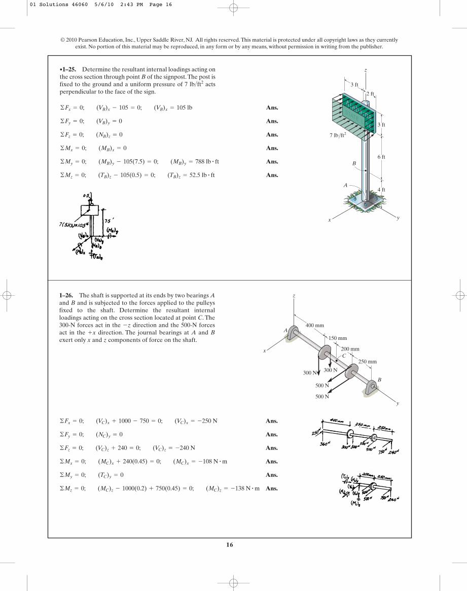
Ans.
Ans.
Ans.
Ans.
Ans.
Ans.©Mz = 0; (TB)z - 105(0.5) = 0; (TB)z = 52.5 lb # ft
©My = 0; (MB)y - 105(7.5) = 0; (MB)y = 788 lb # ft
©Mx = 0; (MB)x = 0
©Fz = 0; (NB)z = 0
©Fy = 0; (VB)y = 0
©Fx = 0; (VB)x - 105 = 0; (VB)x = 105 lb
•1–25. Determine the resultant internal loadings acting onthe cross section through point B of the signpost.The post isfixed to the ground and a uniform pressure of 7 > actsperpendicular to the face of the sign.
ft2lb
4 ft
z
y
6 ft
x
B
A
3 ft
2 ft
3 ft
7 lb/ft2
1–26. The shaft is supported at its ends by two bearings Aand B and is subjected to the forces applied to the pulleysfixed to the shaft. Determine the resultant internalloadings acting on the cross section located at point C. The300-N forces act in the �z direction and the 500-N forcesact in the �x direction. The journal bearings at A and Bexert only x and z components of force on the shaft.
y
B
C
400 mm
150 mm
200 mm
250 mm
A
x
z
300 N 300 N
500 N
500 N
Ans.
Ans.
Ans.
Ans.
Ans.
Ans.©Mz = 0; (MC)z - 1000(0.2) + 750(0.45) = 0; (MC)z = -138 N # m
©My = 0; (TC)y = 0
©Mx = 0; (MC)x + 240(0.45) = 0; (MC)x = -108 N # m
©Fz = 0; (VC)z + 240 = 0; (VC)z = -240 N
©Fy = 0; (NC)y = 0
©Fx = 0; (VC)x + 1000 - 750 = 0; (VC)x = -250 N
01 Solutions 46060 5/6/10 2:43 PM Page 16

17
© 2010 Pearson Education, Inc., Upper Saddle River, NJ. All rights reserved. This material is protected under all copyright laws as they currentlyexist. No portion of this material may be reproduced, in any form or by any means, without permission in writing from the publisher.
Ans.
Ans.
Ans.
Ans.
Ans.
Ans.©Mz = 0; (MB)z = 0
(MB)y = 6.23 N # m
©My = 0; (MB)y + (0.2)(12)(9.81)(0.1) + (0.4)(12)(9.81)(0.2) - 60(0.3) = 0
(TB)x = 9.42 N # m
©Mx = 0; (TB)x + 60(0.4) - 60(0.4) - (0.4)(12)(9.81)(0.2) = 0
(VB)z = 70.6 N
©Fz = 0; (VB)z - 60 + 60 - (0.2)(12)(9.81) - (0.4)(12)(9.81) = 0
©Fy = 0; (VB)y = 0
©Fx = 0; (NB)x = 0
1–27. The pipe has a mass of 12 >m. If it is fixed to thewall at A, determine the resultant internal loadings acting onthe cross section at B. Neglect the weight of the wrench CD.
kg
300 mm
200 mm
150 mm
60 N
60 N400 mm
150 mm
B
A
x
y
z
C
D
01 Solutions 46060 5/6/10 2:43 PM Page 17
18
© 2010 Pearson Education, Inc., Upper Saddle River, NJ. All rights reserved. This material is protected under all copyright laws as they currentlyexist. No portion of this material may be reproduced, in any form or by any means, without permission in writing from the publisher.
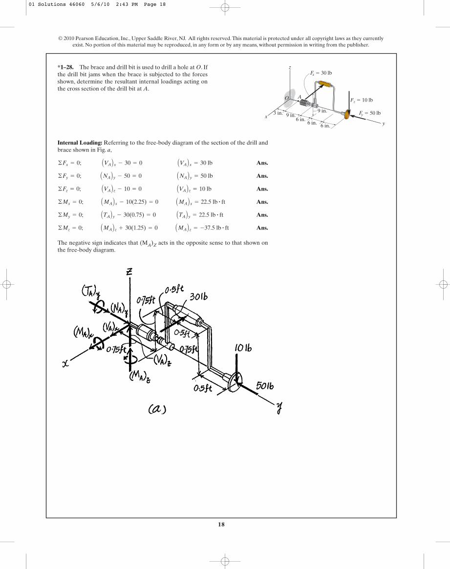
Internal Loading: Referring to the free-body diagram of the section of the drill andbrace shown in Fig. a,
Ans.
Ans.
Ans.
Ans.
Ans.
Ans.
The negative sign indicates that (MA)Z acts in the opposite sense to that shown onthe free-body diagram.
©Mz = 0; AMA Bz + 30(1.25) = 0 AMA Bz = -37.5 lb # ft
©My = 0; ATA By - 30(0.75) = 0 ATA By = 22.5 lb # ft
©Mx = 0; AMA Bx - 10(2.25) = 0 AMA Bx = 22.5 lb # ft
©Fz = 0; AVA Bz - 10 = 0 AVA Bz = 10 lb
©Fy = 0; ANA By - 50 = 0 ANA By = 50 lb
©Fx = 0; AVA Bx - 30 = 0 AVA Bx = 30 lb
*1–28. The brace and drill bit is used to drill a hole at O. Ifthe drill bit jams when the brace is subjected to the forcesshown, determine the resultant internal loadings acting onthe cross section of the drill bit at A.
z
xy
AO
9 in.6 in.
6 in. 6 in.
9 in.3 in.
Fx � 30 lb
Fy � 50 lb
Fz � 10 lb
01 Solutions 46060 5/6/10 2:43 PM Page 18

19
© 2010 Pearson Education, Inc., Upper Saddle River, NJ. All rights reserved. This material is protected under all copyright laws as they currentlyexist. No portion of this material may be reproduced, in any form or by any means, without permission in writing from the publisher.
Equations of Equilibrium: For point A
Ans.
Ans.
Ans. MA = Pr(1 - cos u)
d+ ©MA = 0; MA - P[r(1 - cos u)] = 0
VA = P sin u
Q+ ©Fy = 0; VA - P sin u = 0
NA = P cos u
R+ ©Fx = 0; P cos u - NA = 0
•1–29. The curved rod has a radius r and is fixed to thewall at B. Determine the resultant internal loadings actingon the cross section through A which is located at an angle ufrom the horizontal.
rA
B
P
U
01 Solutions 46060 5/6/10 2:43 PM Page 19

20
© 2010 Pearson Education, Inc., Upper Saddle River, NJ. All rights reserved. This material is protected under all copyright laws as they currentlyexist. No portion of this material may be reproduced, in any form or by any means, without permission in writing from the publisher.
(1)
(2)
(3)
(4)
Since is can add, then ,
Eq. (1) becomes
Neglecting the second order term,
QED
Eq. (2) becomes
Neglecting the second order term,
QED
Eq. (3) becomes
Neglecting the second order term,
QED
Eq. (4) becomes
Neglecting the second order term,
QEDdM
du= -T
Tdu + dM = 0
Tdu + dM +
dTdu
2= 0
dT
du= M
Mdu - dT = 0
Mdu - dT +
dMdu
2= 0
dV
du= -N
Ndu + dV = 0
Ndu + dV +
dNdu
2= 0
dN
du= V
Vdu - dN = 0
Vdu - dN +
dVdu
2= 0
cos du
2= 1sin
du
2=
du
2du
2
T sin du
2- M cos
du
2+ (T + dT) sin
du
2+ (M + dM) cos
du
2= 0
©My = 0;
T cos du
2+ M sin
du
2- (T + dT) cos
du
2+ (M + dM) sin
du
2= 0
©Mx = 0;
N sin du
2- V cos
du
2+ (N + dN) sin
du
2+ (V + dV) cos
du
2= 0
©Fy = 0;
N cos du
2+ V sin
du
2- (N + dN) cos
du
2+ (V + dV) sin
du
2= 0
©Fx = 0;
1–30. A differential element taken from a curved bar isshown in the figure. Show that
and dT>du = M.dM>du = -T,dV>du = -N,dN>du = V,
M V
N du
M � dM T � dT
N � dNV � dV
T
01 Solutions 46060 5/6/10 2:43 PM Page 20

21
© 2010 Pearson Education, Inc., Upper Saddle River, NJ. All rights reserved. This material is protected under all copyright laws as they currentlyexist. No portion of this material may be reproduced, in any form or by any means, without permission in writing from the publisher.
Ans.s =
P
A=
8 (103)
4.4 (10- 3)= 1.82 MPa
= 4400 mm2= 4.4 (10-3) m2
A = (2)(150)(10) + (140)(10)
1–31. The column is subjected to an axial force of 8 kN,which is applied through the centroid of the cross-sectionalarea. Determine the average normal stress acting at sectiona–a. Show this distribution of stress acting over the area’scross section.
8 kN
aa
75 mm
10 mm
10 mm 10 mm75 mm
70 mm
70 mm
a
Ans.tavg =
V
A=
833.33p4( 6
1000)2= 29.5 MPa
+ ©MO = 0; -F(12) + 20(500) = 0; F = 833.33 N
*1–32. The lever is held to the fixed shaft using a taperedpin AB, which has a mean diameter of 6 mm. If a couple isapplied to the lever, determine the average shear stress inthe pin between the pin and lever.
20 N 20 N
250 mm 250 mm
12 mm
A
B
01 Solutions 46060 5/6/10 2:43 PM Page 21

22
© 2010 Pearson Education, Inc., Upper Saddle River, NJ. All rights reserved. This material is protected under all copyright laws as they currentlyexist. No portion of this material may be reproduced, in any form or by any means, without permission in writing from the publisher.
Equations of Equilibrium:
Average Normal Stress and Shear Stress: Area at plane, .
Ans.
Ans. =
P
A sin u cos u =
P
2A sin 2u
tavg =
V
A¿
=
P cos uA
sin u
s =
N
A¿
=
P sin uA
sin u
=
P
A sin2 u
A¿ =
A
sin uu
Q+ ©Fy = 0; N - P sin u = 0 N = P sin u
R+ ©Fx = 0; V - P cos u = 0 V = P cos u
•1–33. The bar has a cross-sectional area A and issubjected to the axial load P. Determine the averagenormal and average shear stresses acting over the shadedsection, which is oriented at from the horizontal. Plot thevariation of these stresses as a function of u 10 … u … 90°2.
u
P
u
P
A
At D:
Ans.
At E:
Ans.sE =
P
A=
8(103)p4 (0.0122)
= 70.7 MPa (T)
sD =
P
A=
4(103)p4 (0.0282
- 0.022)= 13.3 MPa (C)
1–34. The built-up shaft consists of a pipe AB and solidrod BC. The pipe has an inner diameter of 20 mm and outerdiameter of 28 mm. The rod has a diameter of 12 mm.Determine the average normal stress at points D and E andrepresent the stress on a volume element located at each ofthese points.
C
ED
A4 kN
8 kN
B 6 kN
6 kN
01 Solutions 46060 5/6/10 2:43 PM Page 22

23
© 2010 Pearson Education, Inc., Upper Saddle River, NJ. All rights reserved. This material is protected under all copyright laws as they currentlyexist. No portion of this material may be reproduced, in any form or by any means, without permission in writing from the publisher.
Joint A:
Ans.
Ans.
Joint E:
Ans.
Ans.
Joint B:
Ans.
Ans.sBD =
FBD
ABD=
23.331.25
= 18.7 ksi (C)
sBC =
FBC
ABC=
29.331.25
= 23.5 ksi (T)
sEB =
FEB
AEB=
6.01.25
= 4.80 ksi (T)
sED =
FED
AED=
10.671.25
= 8.53 ksi (C)
sAE =
FAE
AAE=
10.671.25
= 8.53 ksi (C)
sAB =
FAB
AAB=
13.331.25
= 10.7 ksi (T)
1–35. The bars of the truss each have a cross-sectionalarea of Determine the average normal stress ineach member due to the loading State whetherthe stress is tensile or compressive.
P = 8 kip.1.25 in2.
3 ft
4 ft 4 ft
P0.75 P
E DA
B C
01 Solutions 46060 5/6/10 2:43 PM Page 23

24
© 2010 Pearson Education, Inc., Upper Saddle River, NJ. All rights reserved. This material is protected under all copyright laws as they currentlyexist. No portion of this material may be reproduced, in any form or by any means, without permission in writing from the publisher.
Joint A:
Joint E:
Joint B:
The highest stressed member is BC:
Ans.P = 6.82 kip
sBC =
(3.67)P
1.25= 20
FBC = (3.67)P
:+ ©Fx = 0; FBC - (2.9167)Pa45b - (1.667)Pa
45b = 0
FBD = (2.9167)P
+ c ©Fy = 0; a35bFBD - (0.75)P - (1.667)Pa
35b = 0
FED = (1.333)P
:+ ©Fx = 0; (1.333)P - FED = 0
FEB = (0.75)P
+ c ©Fy = 0; FEB - (0.75)P = 0
FAE = (1.333)P
:+ ©Fx = 0; -FAE + (1.667)Pa45b = 0
FAB = (1.667)P
+ c ©Fy = 0; -P + a35bFAB = 0
*1–36. The bars of the truss each have a cross-sectionalarea of If the maximum average normal stress inany bar is not to exceed 20 ksi, determine the maximummagnitude P of the loads that can be applied to the truss.
1.25 in2.
3 ft
4 ft 4 ft
P0.75 P
E DA
B C
01 Solutions 46060 5/6/10 2:43 PM Page 24

25
© 2010 Pearson Education, Inc., Upper Saddle River, NJ. All rights reserved. This material is protected under all copyright laws as they currentlyexist. No portion of this material may be reproduced, in any form or by any means, without permission in writing from the publisher.
The resultant force dF of the bearing pressure acting on the plate of area dA = b dx= 0.5 dx, Fig. a,
Ans.
Equilibrium requires
a
Ans. d = 2.40 m
L
4m
0x[7.5(106)x
12 dx] - 40(106) d = 0
+ ©MO = 0; L
xdF - Pd = 0
P = 40(106) N = 40 MN
L
4m
07.5(106)x
12 dx - P = 0
+ c ©Fy = 0; L
dF - P = 0
dF = sb dA = (15x12)(106)(0.5dx) = 7.5(106)x
12 dx
•1–37. The plate has a width of 0.5 m. If the stress distri-bution at the support varies as shown, determine the force Papplied to the plate and the distance d to where it is applied.
4 m
30 MPa
Pd
� (15x ) MPa1/2s
x
01 Solutions 46060 5/6/10 2:43 PM Page 25

26
© 2010 Pearson Education, Inc., Upper Saddle River, NJ. All rights reserved. This material is protected under all copyright laws as they currentlyexist. No portion of this material may be reproduced, in any form or by any means, without permission in writing from the publisher.
Ans.
Ans.t =
V
A¿
=
346.413
= 115 psi
s =
N
A¿
=
2003
= 66.7 psi
A¿ =
1.5(1)
sin 30°= 3 in2
400 cos 30° - V = 0; V = 346.41 lb
N - 400 sin 30° = 0; N = 200 lb
1–38. The two members used in the construction of anaircraft fuselage are joined together using a 30° fish-mouthweld. Determine the average normal and average shearstress on the plane of each weld. Assume each inclinedplane supports a horizontal force of 400 lb.
800 lb 800 lb
30�
1 in.1 in.
1.5 in. 30�
1–39. If the block is subjected to the centrally appliedforce of 600 kN, determine the average normal stress in thematerial. Show the stress acting on a differential volumeelement of the material.
50 mm
150 mm
150 mm50 mm
100 mm100 mm
600 kN150 mm
150 mm
The cross-sectional area of the block is .
Ans.
The average normal stress distribution over the cross-section of the block and thestate of stress of a point in the block represented by a differential volume elementare shown in Fig. a
savg =
P
A=
600(103)
0.12= 5(106) Pa = 5 MPa
A = 0.6(0.3) - 0.3(0.2) = 0.12 m2
01 Solutions 46060 5/6/10 2:43 PM Page 26
27
© 2010 Pearson Education, Inc., Upper Saddle River, NJ. All rights reserved. This material is protected under all copyright laws as they currentlyexist. No portion of this material may be reproduced, in any form or by any means, without permission in writing from the publisher.
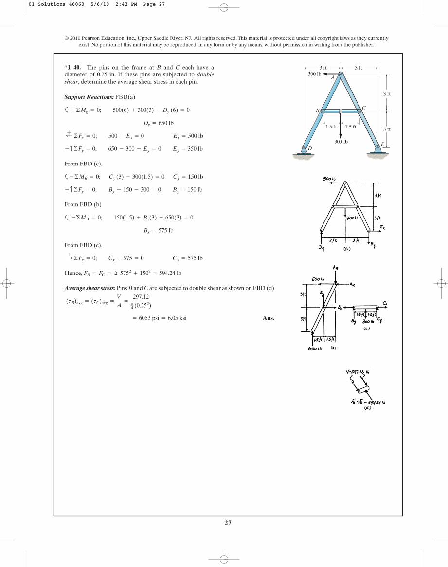
Support Reactions: FBD(a)
a
From FBD (c),
a
From FBD (b)
a
From FBD (c),
Hence,
Average shear stress: Pins B and C are subjected to double shear as shown on FBD (d)
Ans. = 6053 psi = 6.05 ksi
(tB)avg = (tC)avg =
V
A=
297.12p4 (0.252)
FB = FC = 2 5752+ 1502
= 594.24 lb
:+ ©Fx = 0; Cx - 575 = 0 Cx = 575 lb
Bx = 575 lb
+ ©MA = 0; 150(1.5) + Bx(3) - 650(3) = 0
+ c ©Fy = 0; By + 150 - 300 = 0 By = 150 lb
+ ©MB = 0; Cy (3) - 300(1.5) = 0 Cy = 150 lb
+ c ©Fy = 0; 650 - 300 - Ey = 0 Ey = 350 lb
;+ ©Fx = 0; 500 - Ex = 0 Ex = 500 lb
Dy = 650 lb
+ ©Mg = 0; 500(6) + 300(3) - Dy (6) = 0
*1–40. The pins on the frame at B and C each have adiameter of 0.25 in. If these pins are subjected to doubleshear, determine the average shear stress in each pin.
3 ft 3 ft
3 ft
3 ft
1.5 ft
CB
A
DE300 lb
500 lb
1.5 ft
01 Solutions 46060 5/6/10 2:43 PM Page 27

28
© 2010 Pearson Education, Inc., Upper Saddle River, NJ. All rights reserved. This material is protected under all copyright laws as they currentlyexist. No portion of this material may be reproduced, in any form or by any means, without permission in writing from the publisher.
Support Reactions: FBD(a)
a
From FBD (c),
a
From FBD (b)
From FBD (c),
Hence,
Average shear stress: Pins B and C are subjected to single shear as shown on FBD (d)
Ans. = 12106 psi = 12.1 ksi
(tB)avg = (tC)avg =
V
A=
594.24p4 (0.252)
FB = FC = 2 5752+ 1502
= 594.24 lb
:+ ©Fx = 0; Cx - 575 = 0 Cx = 575 lb
Bx = 575 lb
d+ ©MA = 0; 150(1.5) + Bx(3) - 650(3) = 0
+ c ©Fy = 0; By + 150 - 300 = 0 By = 150 lb
+ ©MB = 0; Cy (3) - 300(1.5) = 0 Cy = 150 lb
+ c ©Fy = 0; 650 - 300 - Ey = 0 Ey = 350 lb
;+ ©Fx = 0; 500 - Ex = 0 Ex = 500 lb
Dy = 650 lb
+ ©Mg = 0; 500(6) + 300(3) - Dy (6) = 0
•1–41. Solve Prob. 1–40 assuming that pins B and C aresubjected to single shear.
3 ft 3 ft
3 ft
3 ft
1.5 ft
CB
A
DE300 lb
500 lb
1.5 ft
01 Solutions 46060 5/6/10 2:43 PM Page 28

29
© 2010 Pearson Education, Inc., Upper Saddle River, NJ. All rights reserved. This material is protected under all copyright laws as they currentlyexist. No portion of this material may be reproduced, in any form or by any means, without permission in writing from the publisher.
Support Reactions: FBD(a)
a
Average shear stress: Pins D and E are subjected to double shear as shown on FBD(b) and (c).
For Pin D, then
Ans.
For Pin E, then
Ans. = 6217 psi = 6.22 ksi
(tE)avg =
VE
AE=
305.16p4 (0.252)
VE =
Fg
z = 305.16 lbFE = 2 5002+ 3502
= 610.32 lb
= 6621 psi = 6.62 ksi
(pD)avg =
VD
AD=
325p4 (0.25)2
VD =
FD
z = 325 lbFD = Dy = 650 lb
+ c ©Fy = 0; 650 - 300 - Ey = 0 Ey = 350 lb
;+ ©Fx = 0; 500 - Ex = 0 Ex = 500 lb
Dy = 650 lb
+ ©ME = 0; 500(6) + 300(3) - Dy(6) = 0
1–42. The pins on the frame at D and E each have adiameter of 0.25 in. If these pins are subjected to doubleshear, determine the average shear stress in each pin.
3 ft 3 ft
3 ft
3 ft
1.5 ft
CB
A
DE300 lb
500 lb
1.5 ft
01 Solutions 46060 5/6/10 2:43 PM Page 29

30
© 2010 Pearson Education, Inc., Upper Saddle River, NJ. All rights reserved. This material is protected under all copyright laws as they currentlyexist. No portion of this material may be reproduced, in any form or by any means, without permission in writing from the publisher.
Support Reactions: FBD(a)
a
Average shear stress: Pins D and E are subjected to single shear as shown on FBD(b) and (c).
For Pin D,
Ans.
For Pin E,
Ans. = 12433 psi = 12.4 ksi
(tE)avg =
VE
AE=
610.32p4(0.252)
VE = FE = 2 5002+ 3502
= 610.32 lb
= 13242 psi = 13.2 ksi
(tD)avg =
VD
AD=
650p4(0.252)
VD = FD = Dy = 650 lb
+ c ©Fy = 0; 650 - 300 - Ey = 0 Ey = 350 lb
;+ ©Fx = 0; 500 - Ex = 0 Ex = 500 lb
Dy = 650 lb
+ ©ME = 0; 500(6) + 300(3) - Dy(6) = 0
1–43. Solve Prob. 1–42 assuming that pins D and E aresubjected to single shear.
3 ft 3 ft
3 ft
3 ft
1.5 ft
CB
A
DE300 lb
500 lb
1.5 ft
*1–44. A 175-lb woman stands on a vinyl floor wearingstiletto high-heel shoes. If the heel has the dimensionsshown, determine the average normal stress she exerts onthe floor and compare it with the average normal stressdeveloped when a man having the same weight is wearingflat-heeled shoes. Assume the load is applied slowly, so thatdynamic effects can be ignored. Also, assume the entireweight is supported only by the heel of one shoe.
Stiletto shoes:
Ans.
Flat-heeled shoes:
Ans.s =
P
A=
175 lb3.462 in2 = 50.5 psi
A =
12
(p)(1.2)2+ 2.4(0.5) = 3.462 in2
s =
P
A=
175 lb0.2014 in2 = 869 psi
A =
12
(p)(0.3)2+ (0.6)(0.1) = 0.2014 in2
1.2 in.
0.5 in.
0.1 in.0.3 in.
01 Solutions 46060 5/6/10 2:43 PM Page 30

31
Joint B:
Ans.
Ans.
Joint A:
Ans.sœ
AC =
FAC
AAC=
5000.6
= 833 psi (T)
sBC =
FBC
ABC=
3750.8
= 469 psi (T)
sAB =
FAB
AAB=
6251.5
= 417 psi (C)
•1–45. The truss is made from three pin-connectedmembers having the cross-sectional areas shown in thefigure. Determine the average normal stress developed ineach member when the truss is subjected to the load shown.State whether the stress is tensile or compressive.
© 2010 Pearson Education, Inc., Upper Saddle River, NJ. All rights reserved. This material is protected under all copyright laws as they currentlyexist. No portion of this material may be reproduced, in any form or by any means, without permission in writing from the publisher.
3 ft
4 ft
B
A
C
500 lb
AA
C �
0.6
in.2
ABC � 0.8 in.2
A AB
� 1
.5 in
.2a
Ans.s =
P
A=
135.61(103)
400(10- 6)= 339 MPa
P = 135.61 kN
= 0
+ ©ME = 0; P cos 20°(0.2) - (29.43 cos 30°)(1.2) + (29.43 sin 30°)(0.4 cos 30°)
F = 29.43 kN
+ c ©Fy = 0; 2(F sin 30°) - 29.43 = 0
1–46. Determine the average normal stress developed inlinks AB and CD of the smooth two-tine grapple thatsupports the log having a mass of 3 Mg. The cross-sectionalarea of each link is 400 mm2.
30�
0.2 m
1.2 m
A C
E DB
20�
0.4 m30�
01 Solutions 46060 5/6/10 2:43 PM Page 31

32
© 2010 Pearson Education, Inc., Upper Saddle River, NJ. All rights reserved. This material is protected under all copyright laws as they currentlyexist. No portion of this material may be reproduced, in any form or by any means, without permission in writing from the publisher.
a
Ans.tA = tB =
V
A=
135.61(103)2
p4 (0.025)2 = 138 MPa
P = 135.61 kN
= 0
+ ©ME = 0; P cos 20°(0.2) - (29.43 cos 30°)(1.2) + (29.43 sin 30°)(0.4 cos 30°)
F = 29.43 kN
+ c ©Fy = 0; 2(F sin 30°) - 29.43 = 0
1–47. Determine the average shear stress developed in pinsA and B of the smooth two-tine grapple that supports the loghaving a mass of 3 Mg. Each pin has a diameter of 25 mm andis subjected to double shear.
30�
0.2 m
1.2 m
A C
E DB
20�
0.4 m30�
For pins B and C:
Ans.
For pin A:
Ans.tA =
V
A=
82.5 (103)p4 ( 18
1000)2= 324 MPa
FA = 2 (82.5)2+ (142.9)2
= 165 kN
tB = tC =
V
A=
82.5 (103)p4 ( 18
1000)2= 324 MPa
*1–48. The beam is supported by a pin at A and a shortlink BC. If P = 15 kN, determine the average shear stressdeveloped in the pins at A, B, and C. All pins are in doubleshear as shown, and each has a diameter of 18 mm.
C
BA
0.5m1 m 1.5 m 1.5 m
0.5 mP 4P 4P 2P
30�
01 Solutions 46060 5/6/10 2:43 PM Page 32
33
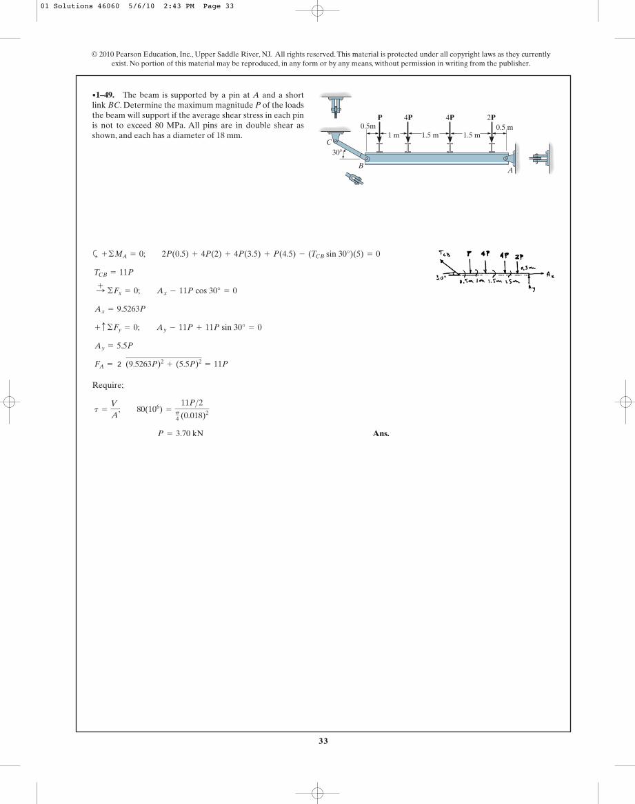
a
Require;
Ans. P = 3.70 kN
t =
V
A; 80(106) =
11P>2p4 (0.018)2
FA = 2 (9.5263P)2+ (5.5P)2
= 11P
Ay = 5.5P
+ c ©Fy = 0; Ay - 11P + 11P sin 30° = 0
Ax = 9.5263P
:+ ©Fx = 0; Ax - 11P cos 30° = 0
TCB = 11P
+ ©MA = 0; 2P(0.5) + 4P(2) + 4P(3.5) + P(4.5) - (TCB sin 30°)(5) = 0
•1–49. The beam is supported by a pin at A and a shortlink BC. Determine the maximum magnitude P of the loadsthe beam will support if the average shear stress in each pinis not to exceed 80 MPa. All pins are in double shear asshown, and each has a diameter of 18 mm.
© 2010 Pearson Education, Inc., Upper Saddle River, NJ. All rights reserved. This material is protected under all copyright laws as they currentlyexist. No portion of this material may be reproduced, in any form or by any means, without permission in writing from the publisher.
C
BA
0.5m1 m 1.5 m 1.5 m
0.5 mP 4P 4P 2P
30�
01 Solutions 46060 5/6/10 2:43 PM Page 33

34
© 2010 Pearson Education, Inc., Upper Saddle River, NJ. All rights reserved. This material is protected under all copyright laws as they currentlyexist. No portion of this material may be reproduced, in any form or by any means, without permission in writing from the publisher.
Force equilibrium equations written perpendicular and parallel to section a–a gives
The cross sectional area of section a–a is . Thus
Ans.
Ans.(ta - a)avg =
Va - a
A=
1.732(103)
0.015= 115.47(103)Pa = 115 kPa
(sa - a)avg =
Na - a
A=
1.00(103)
0.015= 66.67(103)Pa = 66.7 kPa
A = a0.15
sin 30°b(0.05) = 0.015 m2
+a©Fy¿= 0; 2 sin 30° - Na - a = 0 Na - a = 1.00 kN
+Q©Fx¿= 0; Va - a - 2 cos 30° = 0 Va - a = 1.732 kN
1–50. The block is subjected to a compressive force of2 kN. Determine the average normal and average shearstress developed in the wood fibers that are oriented alongsection a–a at 30° with the axis of the block.
150 mm2 kN 2 kN
a
30�
50 mm
a
01 Solutions 46060 5/6/10 2:43 PM Page 34

35
Internal Loading: The normal force developed on the cross section of the middleportion of the specimen can be obtained by considering the free-body diagramshown in Fig. a.
Referring to the free-body diagram shown in fig. b, the shear force developed in theshear plane a–a is
Average Normal Stress and Shear Stress: The cross-sectional area of the specimen is. We have
Ans.
Using the result of P, . The area of the shear plane is
. We obtain
Ans.Ata - a Bavg =
Va - a
Aa - a=
2(103)
8= 250 psi
Aa - a = 2(4) = 8 in2
Va - a =
P
2=
4(103)
2= 2(103) lb
P = 4(103)lb = 4 kip
savg =
N
A; 2(103) =
P
2
A = 1(2) = 2 in2
+ c ©Fy = 0; P
2- Va - a = 0 Va - a =
P
2
+ c ©Fy = 0; P
2+
P
2- N = 0 N = P
1–51. During the tension test, the wooden specimen issubjected to an average normal stress of 2 ksi. Determinethe axial force P applied to the specimen. Also, find theaverage shear stress developed along section a–a of the specimen.
© 2010 Pearson Education, Inc., Upper Saddle River, NJ. All rights reserved. This material is protected under all copyright laws as they currentlyexist. No portion of this material may be reproduced, in any form or by any means, without permission in writing from the publisher.
P
P
1 in.2 in.
4 in.
4 in.
a
a
01 Solutions 46060 5/6/10 2:43 PM Page 35

36
*1–52. If the joint is subjected to an axial force of, determine the average shear stress developed in
each of the 6-mm diameter bolts between the plates and themembers and along each of the four shaded shear planes.
P = 9 kN
© 2010 Pearson Education, Inc., Upper Saddle River, NJ. All rights reserved. This material is protected under all copyright laws as they currentlyexist. No portion of this material may be reproduced, in any form or by any means, without permission in writing from the publisher.
P
P
100 mm
100 mmInternal Loadings: The shear force developed on each shear plane of the bolt andthe member can be determined by writing the force equation of equilibrium alongthe member’s axis with reference to the free-body diagrams shown in Figs. a. and b,respectively.
Average Shear Stress: The areas of each shear plane of the bolt and the member
are and , respectively.
We obtain
Ans.
Ans.Atavg Bp =
Vp
Ap=
2.25(103)
0.01= 225 kPa
Atavg Bb =
Vb
Ab=
2.25(103)
28.274(10- 6)= 79.6 MPa
Ap = 0.1(0.1) = 0.01 m2Ab =
p
4 (0.0062) = 28.274(10- 6)m2
©Fy = 0; 4Vp - 9 = 0 Vp = 2.25 kN
©Fy = 0; 4Vb - 9 = 0 Vb = 2.25 kN
01 Solutions 46060 5/6/10 2:43 PM Page 36

37
Internal Loadings: The shear force developed on each shear plane of the bolt andthe member can be determined by writing the force equation of equilibrium alongthe member’s axis with reference to the free-body diagrams shown in Figs. a. and b,respectively.
Average Shear Stress: The areas of each shear plane of the bolts and the members
are and , respectively.
We obtain
Ans.
P = 20 000 N = 20 kN
Atallow Bp =
Vp
Ap ; 500(103) =
P>4
0.01
P = 9047 N = 9.05 kN (controls)
Atallow Bb =
Vb
Ab; 80(106) =
P>4
28.274(10- 6)
Ap = 0.1(0.1) = 0.01m2Ab =
p
4 (0.0062) = 28.274(10- 6)m2
©Fy = 0; 4Vp - P = 0 Vp = P>4
©Fy = 0; 4Vb - P = 0 Vb = P>4
•1–53. The average shear stress in each of the 6-mm diameterbolts and along each of the four shaded shear planes is notallowed to exceed 80 MPa and 500 kPa, respectively.Determine the maximum axial force P that can be appliedto the joint.
© 2010 Pearson Education, Inc., Upper Saddle River, NJ. All rights reserved. This material is protected under all copyright laws as they currentlyexist. No portion of this material may be reproduced, in any form or by any means, without permission in writing from the publisher.
P
P
100 mm
100 mm
01 Solutions 46060 5/6/10 2:43 PM Page 37

38
Referring to the FBDs in Fig. a,
Here, the cross-sectional area of the shaft and the bearing area of the collar are
and . Thus,
Ans.
Ans.Asavg Bb =
Nb
Ab=
40(103)
0.4(10- 3)p= 31.83(106)Pa = 31.8 MPa
Asavg B s =
Ns
As=
40(103)
0.225(10- 3)p= 56.59(106) Pa = 56.6 MPa
Ab =
p
4 (0.042) = 0.4(10- 3)p m2As =
p
4 (0.032) = 0.225(10- 3)p m2
+ c ©Fy = 0; Nb - 40 = 0 Nb = 40 kN
+ c ©Fy = 0; Ns - 40 = 0 Ns = 40 kN
1–54. The shaft is subjected to the axial force of 40 kN.Determine the average bearing stress acting on the collar Cand the normal stress in the shaft.
© 2010 Pearson Education, Inc., Upper Saddle River, NJ. All rights reserved. This material is protected under all copyright laws as they currentlyexist. No portion of this material may be reproduced, in any form or by any means, without permission in writing from the publisher.
40 kN
30 mm
40 mm
C
01 Solutions 46060 5/6/10 2:43 PM Page 38

39
© 2010 Pearson Education, Inc., Upper Saddle River, NJ. All rights reserved. This material is protected under all copyright laws as they currentlyexist. No portion of this material may be reproduced, in any form or by any means, without permission in writing from the publisher.
1–55. Rods AB and BC each have a diameter of 5 mm. Ifthe load of is applied to the ring, determine theaverage normal stress in each rod if .u = 60°
P = 2 kN
u
C
B
P
A
Consider the equilibrium of joint B, Fig. a,
The cross-sectional area of wires AB and BC are
. Thus,
Ans.
Ans.Asavg BBC =
FBC
ABC=
1.155(103)
6.25(10- 6)p= 58.81(106) Pa = 58.8 MPa
Asavg BAB =
FAB
AAB=
2.309(103)
6.25(10- 6)p= 117.62(106) Pa = 118 MPa
= 6.25(10- 6)p m2
AAB = ABC =
p
4 (0.0052)
+ c ©Fy = 0; 2.309 cos 60° - FBC = 0 FBC = 1.155 kN
:+ ©Fx = 0; 2 - FAB sin 60° = 0 FAB = 2.309 kN
01 Solutions 46060 5/6/10 2:43 PM Page 39
40
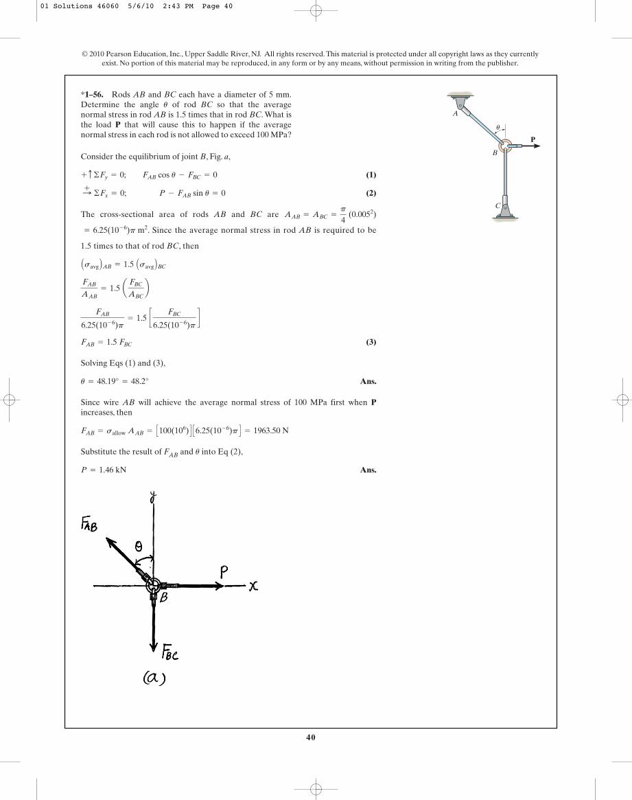
Consider the equilibrium of joint B, Fig. a,
(1)
(2)
The cross-sectional area of rods AB and BC are
. Since the average normal stress in rod AB is required to be
1.5 times to that of rod BC, then
(3)
Solving Eqs (1) and (3),
Ans.
Since wire AB will achieve the average normal stress of 100 MPa first when Pincreases, then
Substitute the result of FAB and into Eq (2),
Ans.P = 1.46 kN
u
FAB = sallow AAB = C100(106) D C6.25(10- 6)p D = 1963.50 N
u = 48.19° = 48.2°
FAB = 1.5 FBC
FAB
6.25(10- 6)p= 1.5 c
FBC
6.25(10- 6)pd
FAB
AAB= 1.5 a
FBC
ABCb
Asavg BAB = 1.5 Asavg BBC
= 6.25(10- 6)p m2
AAB = ABC =
p
4 (0.0052)
:+ ©Fx = 0; P - FAB sin u = 0
+ c ©Fy = 0; FAB cos u - FBC = 0
*1–56. Rods AB and BC each have a diameter of 5 mm.Determine the angle of rod BC so that the averagenormal stress in rod AB is 1.5 times that in rod BC. What isthe load P that will cause this to happen if the averagenormal stress in each rod is not allowed to exceed 100 MPa?
u
© 2010 Pearson Education, Inc., Upper Saddle River, NJ. All rights reserved. This material is protected under all copyright laws as they currentlyexist. No portion of this material may be reproduced, in any form or by any means, without permission in writing from the publisher.
u
C
B
P
A
01 Solutions 46060 5/6/10 2:43 PM Page 40

41
Inclined plane:
Ans.
Ans.
Cross section:
Ans.
Ans.tavg =
V
A ; tavg = 0
s =
P
A ; s =
19.80p(0.25)2 = 101 ksi
tœ
avg =
V
A ; tœ
avg =
12.19p(0.25)2
sin 52°
= 48.9 ksi
s¿ =
P
A ; s¿ =
15.603p(0.25)2
sin 52°
= 62.6 ksi
N = 15.603 kip
+a © Fy = 0; N - 19.80 sin 52° = 0
V = 12.19 kip
+b © Fx = 0; V - 19.80 cos 52° = 0
•1–57. The specimen failed in a tension test at an angle of52° when the axial load was 19.80 kip. If the diameter of thespecimen is 0.5 in., determine the average normal andaverage shear stress acting on the area of the inclinedfailure plane. Also, what is the average normal stress actingon the cross section when failure occurs?
© 2010 Pearson Education, Inc., Upper Saddle River, NJ. All rights reserved. This material is protected under all copyright laws as they currentlyexist. No portion of this material may be reproduced, in any form or by any means, without permission in writing from the publisher.
52�
0.5 in.
Average Normal Stress:
For the frustum,
Average Shear Stress:
For the cylinder,
Equation of Equilibrium:
Ans. P = 68.3 kN
+ c ©Fy = 0; P - 21.21 - 66.64 sin 45° = 0
F2 = 21.21 kN
tavg =
V
A ; 4.5 A106 B =
F2
0.004712
A = p(0.05)(0.03) = 0.004712 m2
F1 = 66.64 kN
s =
P
A ; 3 A106 B =
F1
0.02221
= 0.02221 m2
A = 2pxL = 2p(0.025 + 0.025) A 2 0.052+ 0.052 B
1–58. The anchor bolt was pulled out of the concrete walland the failure surface formed part of a frustum andcylinder. This indicates a shear failure occurred along thecylinder BC and tension failure along the frustum AB. Ifthe shear and normal stresses along these surfaces have themagnitudes shown, determine the force P that must havebeen applied to the bolt.
30 mm4.5 MPa
3 MPa 3 MPa
P
50 mm
A
25 mm 25 mm
B
C
45�45�
01 Solutions 46060 5/6/10 2:43 PM Page 41
42
© 2010 Pearson Education, Inc., Upper Saddle River, NJ. All rights reserved. This material is protected under all copyright laws as they currentlyexist. No portion of this material may be reproduced, in any form or by any means, without permission in writing from the publisher.
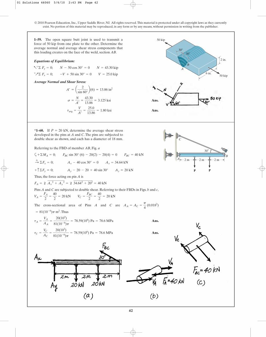
1–59. The open square butt joint is used to transmit aforce of 50 kip from one plate to the other. Determine theaverage normal and average shear stress components thatthis loading creates on the face of the weld, section AB.
30�
30�
50 kip
50 kip
2 in.
6 in.A
BEquations of Equilibrium:
Average Normal and Shear Stress:
Ans.
Ans.tavg =
V
A¿
=
25.013.86
= 1.80 ksi
s =
N
A¿
=
43.3013.86
= 3.125 ksi
A¿ = a2
sin 60°b(6) = 13.86 in2
+
Q© Fx = 0; -V + 50 sin 30° = 0 V = 25.0 kip
a+
© Fy = 0; N - 50 cos 30° = 0 N = 43.30 kip
*1–60. If , determine the average shear stressdeveloped in the pins at A and C. The pins are subjected todouble shear as shown, and each has a diameter of 18 mm.
P = 20 kN
C
P P
2 m2 m2 mAB
30�Referring to the FBD of member AB, Fig. a
a
Thus, the force acting on pin A is
Pins A and C are subjected to double shear. Referring to their FBDs in Figs. b and c,
The cross-sectional area of Pins A and C are
. Thus
Ans.
Ans.tC =
VC
AC=
20(103)
81(10- 6)p= 78.59(106) Pa = 78.6 MPa
tA =
VA
AA=
20(103)
81(10- 6)p= 78.59(106) Pa = 78.6 MPa
= 81(10- 6)p m2
AA = AC =
p
4 (0.0182)
VA =
FA
2=
402
= 20 kN VC =
FBC
2=
402
= 20 kN
FA = 2 Ax 2
+ Ay 2
= 2 34.642+ 202
= 40 kN
+ c ©Fy = 0; Ay - 20 - 20 + 40 sin 30° Ay = 20 kN
:+ ©Fx = 0; Ax - 40 cos 30° = 0 Ax = 34.64 kN
+ ©MA = 0; FBC sin 30° (6) - 20(2) - 20(4) = 0 FBC = 40 kN
01 Solutions 46060 5/6/10 2:43 PM Page 42

43
© 2010 Pearson Education, Inc., Upper Saddle River, NJ. All rights reserved. This material is protected under all copyright laws as they currentlyexist. No portion of this material may be reproduced, in any form or by any means, without permission in writing from the publisher.
Referring to the FBD of member AB, Fig. a,
a
Thus, the force acting on pin A is
All pins are subjected to same force and double shear. Referring to the FBD of thepin, Fig. b,
The cross-sectional area of the pin is . Thus,
Ans. P = 15 268 N = 15.3 kN
tallow =
V
A ; 60(106) =
P
81.0(10- 6)p
A =
p
4 (0.0182) = 81.0(10- 6)p m2
V =
F
2=
2P
2= P
FA = 2 Ax 2
+ Ay 2
= 2 (1.732P)2+ P2
= 2P
+ c ©Fy = 0; Ay - P - P + 2P sin 30° = 0 Ay = P
:+ ©Fx = 0; Ax - 2P cos 30° = 0 Ax = 1.732P
+ ©MA = 0; FBC sin 30°(6) - P(2) - P(4) = 0 FBC = 2P
•1–61. Determine the maximum magnitude P of the loadthe beam will support if the average shear stress in each pinis not to allowed to exceed 60 MPa.All pins are subjected todouble shear as shown, and each has a diameter of 18 mm.
C
P P
2 m2 m2 mAB
30�
01 Solutions 46060 5/6/10 2:43 PM Page 43

44
© 2010 Pearson Education, Inc., Upper Saddle River, NJ. All rights reserved. This material is protected under all copyright laws as they currentlyexist. No portion of this material may be reproduced, in any form or by any means, without permission in writing from the publisher.
Support Reactions:
From FBD(a)
a
From FBD(b)
a
Average Shear Stress: Pin A is subjected to double shear. Hence,
Ans. = 3714 psi = 3.71 ksi
(tA)avg =
VA
AA=
116.67p4 (0.22)
VA =
FA
2=
Ay
2= 116.67 lb
Ay = 233.33 lb
+ ©ME = 0; Ay (1.5) - 100(3.5) = 0
:+ ©Fx = 0; Ax = 0
:+ ©Fx = 0; Bx = 0
+ ©MD = 0; 20(5) - By (1) = 0 By = 100 lb
1–62. The crimping tool is used to crimp the end of thewire E. If a force of 20 lb is applied to the handles,determine the average shear stress in the pin at A.The pin issubjected to double shear and has a diameter of 0.2 in. Onlya vertical force is exerted on the wire.
A
20 lb
20 lb
5 in.1.5 in. 2 in. 1 in.
E C
B D
Support Reactions:
From FBD(a)
a
Average Shear Stress: Pin B is subjected to double shear. Hence,
Ans. = 1592 psi = 1.59 ksi
(tB)avg =
VB
AB=
50.0p4 (0.22)
VB =
FB
2=
By
2= 50.0 lb
:+ ©Fx = 0; Bx = 0
+ ©MD = 0; 20(5) - By (1) = 0 By = 100 lb
1–63. Solve Prob. 1–62 for pin B. The pin is subjected todouble shear and has a diameter of 0.2 in.
A
20 lb
20 lb
5 in.1.5 in. 2 in. 1 in.
E C
B D
01 Solutions 46060 5/6/10 2:43 PM Page 44

45
© 2010 Pearson Education, Inc., Upper Saddle River, NJ. All rights reserved. This material is protected under all copyright laws as they currentlyexist. No portion of this material may be reproduced, in any form or by any means, without permission in writing from the publisher.
*1–64. The triangular blocks are glued along each side ofthe joint. A C-clamp placed between two of the blocks isused to draw the joint tight. If the glue can withstand amaximum average shear stress of 800 kPa, determine themaximum allowable clamping force F.
50 mm
45�
25 mm
F
F
glue
50 mm
45�
25 mm
F
F
glue
Internal Loadings: The shear force developed on the glued shear plane can beobtained by writing the force equation of equilibrium along the x axis withreference to the free-body diagram of the triangular block, Fig. a.
Average Normal and Shear Stress: The area of the glued shear plane is. We obtain
Ans. F = 1414 N = 1.41 kN
tavg =
V
A ; 800(103) =
2 22
F
1.25(10- 3)
A = 0.05(0.025) = 1.25(10- 3)m2
:+ ©Fx = 0; F cos 45° - V = 0 V =
2 22
F
Internal Loadings: The shear force developed on the glued shear plane can beobtained by writing the force equation of equilibrium along the x axis withreference to the free-body diagram of the triangular block, Fig. a.
Average Normal and Shear Stress: The area of the glued shear plane is. We obtain
Ans.tavg =
V
A=
636.401.25(10- 3)
= 509 kPa
A = 0.05(0.025) = 1.25(10- 3)m2
:+ ©Fx = 0; 900 cos 45° - V = 0 V = 636.40 N
•1–65. The triangular blocks are glued along each side ofthe joint. A C-clamp placed between two of the blocks isused to draw the joint tight. If the clamping force is
, determine the average shear stress developedin the glued shear plane.F = 900 N
01 Solutions 46060 5/6/10 2:43 PM Page 45

46
© 2010 Pearson Education, Inc., Upper Saddle River, NJ. All rights reserved. This material is protected under all copyright laws as they currentlyexist. No portion of this material may be reproduced, in any form or by any means, without permission in writing from the publisher.
Analyse the equilibrium of joint C using the FBD Shown in Fig. a,
Referring to the FBD of the cut segment of member BC Fig. b.
The cross-sectional area of section a–a is
. For Normal stress,
For Shear Stress
Ans. P = 62.5(103) N = 62.5 kN (Controls!)
tallow =
Va - a
Aa - a ; 60(106) =
P
1.0417(10- 3)
P = 208.33(103) N = 208.33 kN
sallow =
Na - a
Aa - a ; 150(106) =
0.75P
1.0417(10- 3)
= 1.0417(10- 3)m2
Aa - a = (0.025)a0.0253>5b
+ c ©Fy = 0; 1.25Pa45b - Va - a = 0 Va - a = P
:+ ©Fx = 0; Na - a - 1.25Pa35b = 0 Na - a = 0.75P
+ c ©Fy = 0; FBC a45b - P = 0 FBC = 1.25P
1–66. Determine the largest load P that can be a appliedto the frame without causing either the average normalstress or the average shear stress at section a–a to exceed
and , respectively. Member CBhas a square cross section of 25 mm on each side.
t = 60 MPas = 150 MPa
2 m
B
AC
1.5 m
a
a
P
01 Solutions 46060 5/6/10 2:43 PM Page 46
47
© 2010 Pearson Education, Inc., Upper Saddle River, NJ. All rights reserved. This material is protected under all copyright laws as they currentlyexist. No portion of this material may be reproduced, in any form or by any means, without permission in writing from the publisher.
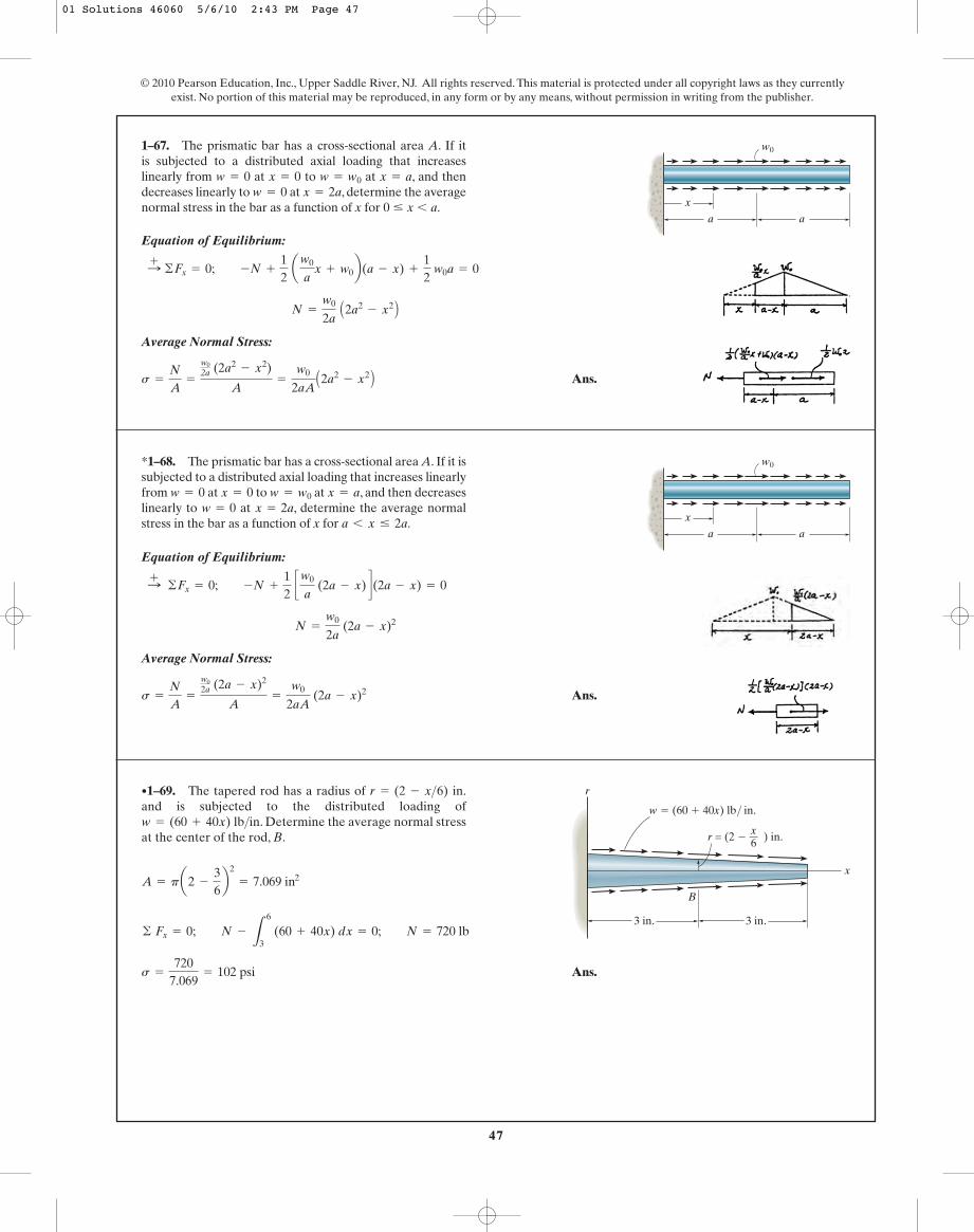
Equation of Equilibrium:
Average Normal Stress:
Ans.s =
N
A=
w02a (2a2
- x2)
A=
w0
2aAA2a2
- x2 B
N =
w0
2a A2a2
- x2 B
:+ ©Fx = 0; -N +
12
aw0
ax + w0b(a - x) +
12
w0
a = 0
1–67. The prismatic bar has a cross-sectional area A. If itis subjected to a distributed axial loading that increaseslinearly from at to at , and thendecreases linearly to at , determine the averagenormal stress in the bar as a function of x for 0 … x 6 a.
x = 2aw = 0x = aw = w0x = 0w = 0
x
a a
w0
Equation of Equilibrium:
Average Normal Stress:
Ans.s =
N
A=
w02a (2a - x)2
A=
w0
2aA (2a - x)2
N =
w0
2a (2a - x)2
:+ ©Fx = 0; -N +
12
cw0
a (2a - x) d(2a - x) = 0
*1–68. The prismatic bar has a cross-sectional area A. If it issubjected to a distributed axial loading that increases linearlyfrom at to at , and then decreaseslinearly to at , determine the average normalstress in the bar as a function of x for .a 6 x … 2a
x = 2aw = 0x = aw = w0x = 0w = 0
x
a a
w0
Ans.s =
7207.069
= 102 psi
© Fx = 0; N -
L
6
3 (60 + 40x) dx = 0; N = 720 lb
A = pa2 -
36b
2
= 7.069 in2
•1–69. The tapered rod has a radius of in.and is subjected to the distributed loading of
>in. Determine the average normal stressat the center of the rod, B.w = (60 + 40x) lb
r = (2 - x>6)
w � (60 � 40x) lb/ in.
r = (2 � ) in.
x
3 in. 3 in.
r
x—6
B
01 Solutions 46060 5/6/10 2:43 PM Page 47

48
© 2010 Pearson Education, Inc., Upper Saddle River, NJ. All rights reserved. This material is protected under all copyright laws as they currentlyexist. No portion of this material may be reproduced, in any form or by any means, without permission in writing from the publisher.
Require:
(1)
From Eq. (1)
However,
Ans.r = r1 e(p r1
2rg2P
)z
s =
P
p r12
rg z
2s= ln
rr1
; r = r1 e(p2a)z
rg
2s L
z
0dz =
L
r
r1
drr
r rg dz
2 dr= s
pr2(rg) dz
2p r dr= s
dW = pr2(rg) dt
dA = p(r + dr)2- pr2
= 2p r dr
dW
dA=
P + W1
A= s
P dA + W1 dA = A dW
s =
P + W1
A=
P + W1 + dW
A + dA
1–70. The pedestal supports a load P at its center. If thematerial has a mass density determine the radialdimension r as a function of z so that the average normalstress in the pedestal remains constant. The cross sectionis circular.
r,
z
r
P
r1
01 Solutions 46060 5/6/10 2:43 PM Page 48

49
Consider the FBD of member BC, Fig. a,
a
Referring to the FBD in Fig. b,
Referring to the FBD in Fig. c.
The cross-sectional areas of section a–a and b–b are and
. Thus
Ans.
Ans.tb - b =
Vb - b
Ab - b=
3000.5
= 600 psi
sa - a =
Na - a
Aa - a=
346.410.25
= 1385.64 psi = 1.39 ksi
Ab - b = 0.5 a0.5
cos 60°b = 0.5 in2
Aa - a = 0.5(0.5) = 0.25 in2
+ c ©Fy = 0; Vb - b - 346.41 sin 60° = 0 Vb - b = 300 lb
+
b©Fx¿= 0; Na - a + 346.41 = 0 Na - a = -346.41 lb
+ ©MC = 0; FAB sin 60°(4) - 150(4)(2) = 0 FAB = 346.41 lb
1–71. Determine the average normal stress at section a–aand the average shear stress at section b–b in member AB.The cross section is square, 0.5 in. on each side.
© 2010 Pearson Education, Inc., Upper Saddle River, NJ. All rights reserved. This material is protected under all copyright laws as they currentlyexist. No portion of this material may be reproduced, in any form or by any means, without permission in writing from the publisher.
150 lb/ft
B
A
C 4 ft
b
b
a
a
60�
01 Solutions 46060 5/6/10 2:43 PM Page 49

50
© 2010 Pearson Education, Inc., Upper Saddle River, NJ. All rights reserved. This material is protected under all copyright laws as they currentlyexist. No portion of this material may be reproduced, in any form or by any means, without permission in writing from the publisher.
Ans.Use h = 2 34
in.
h = 2.74 in.
tallow = 300 =
307.7
(32) h
•1–73. Member B is subjected to a compressive force of800 lb. If A and B are both made of wood and are thick,determine to the nearest the smallest dimension h ofthe horizontal segment so that it does not fail in shear. Theaverage shear stress for the segment is tallow = 300 psi.
14 in.
38 in.
800 lbB
hA
12
513
a
Ans. d = 0.00571 m = 5.71 mm
tallow =
Fa - a
Aa - a ; 35(106) =
5000d(0.025)
Fa - a = 5000 N
+ ©MA = 0; Fa - a (20) - 200(500) = 0
1–74. The lever is attached to the shaft A using a key thathas a width d and length of 25 mm. If the shaft is fixed anda vertical force of 200 N is applied perpendicular to thehandle, determine the dimension d if the allowable shearstress for the key is tallow = 35 MPa. 500 mm
20 mm
daa
A
200 N
Ans.d = 0.0135 m = 13.5 mm
tallow = 140(106) =
20(103)p4 d2
350(106)
2.5= 140(105)
1–75. The joint is fastened together using two bolts.Determine the required diameter of the bolts if the failureshear stress for the bolts is Use a factor ofsafety for shear of F.S. = 2.5.
tfail = 350 MPa.
80 kN
40 kN
30 mm
30 mm
40 kN
01 Solutions 46060 5/6/10 2:43 PM Page 50

51
© 2010 Pearson Education, Inc., Upper Saddle River, NJ. All rights reserved. This material is protected under all copyright laws as they currentlyexist. No portion of this material may be reproduced, in any form or by any means, without permission in writing from the publisher.
Allowable Normal Stress: Design of belt thickness.
Ans.
Allowable Shear Stress: Design of lap length.
Ans.
Allowable Shear Stress: Design of pin size.
Ans. dr = 0.004120 m = 4.12 mm
(tallow)P =
VB
A ; 30 A106 B =
400p4 dr
2
dt = 0.01185 m = 11.9 mm
(tallow)g =
VA
A ; 0.750 A106 B =
400(0.045) dt
t = 0.001778 m = 1.78 mm
(st)allow =
P
A ; 10 A106 B =
800(0.045)t
*1–76. The lapbelt assembly is to be subjected to a forceof 800 N. Determine (a) the required thickness t ofthe belt if the allowable tensile stress for the materialis (b) the required lap length if the glue can sustain an allowable shear stress of
and (c) the required diameter ofthe pin if the allowable shear stress for the pin is(tallow)p = 30 MPa.
dr(tallow)g = 0.75 MPa,
dl(st)allow = 10 MPa,
800 N
800 N
t
dr
dl
45 mm
Allowable Shear Stress: Shear limitation
Ans.
Allowable Normal Stress: Tension limitation
Ans. b = 0.03333 m = 33.3 mm
sallow =
P
A ; 12.0 A106 B =
10(103)
(0.025) b
t = 0.1667 m = 167 mm
tallow =
V
A ; 1.2 A106 B =
5.00(103)
(0.025) t
•1–77. The wood specimen is subjected to the pull of 10 kN in a tension testing machine. If the allowable normalstress for the wood is and the allowableshear stress is determine the requireddimensions b and t so that the specimen reaches thesestresses simultaneously.The specimen has a width of 25 mm.
tallow = 1.2 MPa,(st)allow = 12 MPa
10 kN
10 kN
A t
b
01 Solutions 46060 5/6/10 2:43 PM Page 51

52
Consider the equilibrium of the FBD of member B, Fig. a,
Referring to the FBD of the wood segment sectioned through glue line, Fig. b
The area of shear plane is . Thus,
Ans. Use a = 612 in.
a = 6.40 in
tallow =
V
A ; 50 =
4801.5a
A = 1.5(a)
:+ ©Fx = 0; 480 - V = 0 V = 480 lb
:+ ©Fx = 0; 600a45b - Fh = 0 Fh = 480 lb
1–78. Member B is subjected to a compressive force of600 lb. If A and B are both made of wood and are 1.5 in.thick, determine to the nearest the smallest dimensiona of the support so that the average shear stress along theblue line does not exceed . Neglect friction.tallow = 50 psi
1>8 in.
© 2010 Pearson Education, Inc., Upper Saddle River, NJ. All rights reserved. This material is protected under all copyright laws as they currentlyexist. No portion of this material may be reproduced, in any form or by any means, without permission in writing from the publisher.
600 lb
a
A
B4
53
01 Solutions 46060 5/6/10 2:43 PM Page 52
53
© 2010 Pearson Education, Inc., Upper Saddle River, NJ. All rights reserved. This material is protected under all copyright laws as they currentlyexist. No portion of this material may be reproduced, in any form or by any means, without permission in writing from the publisher.
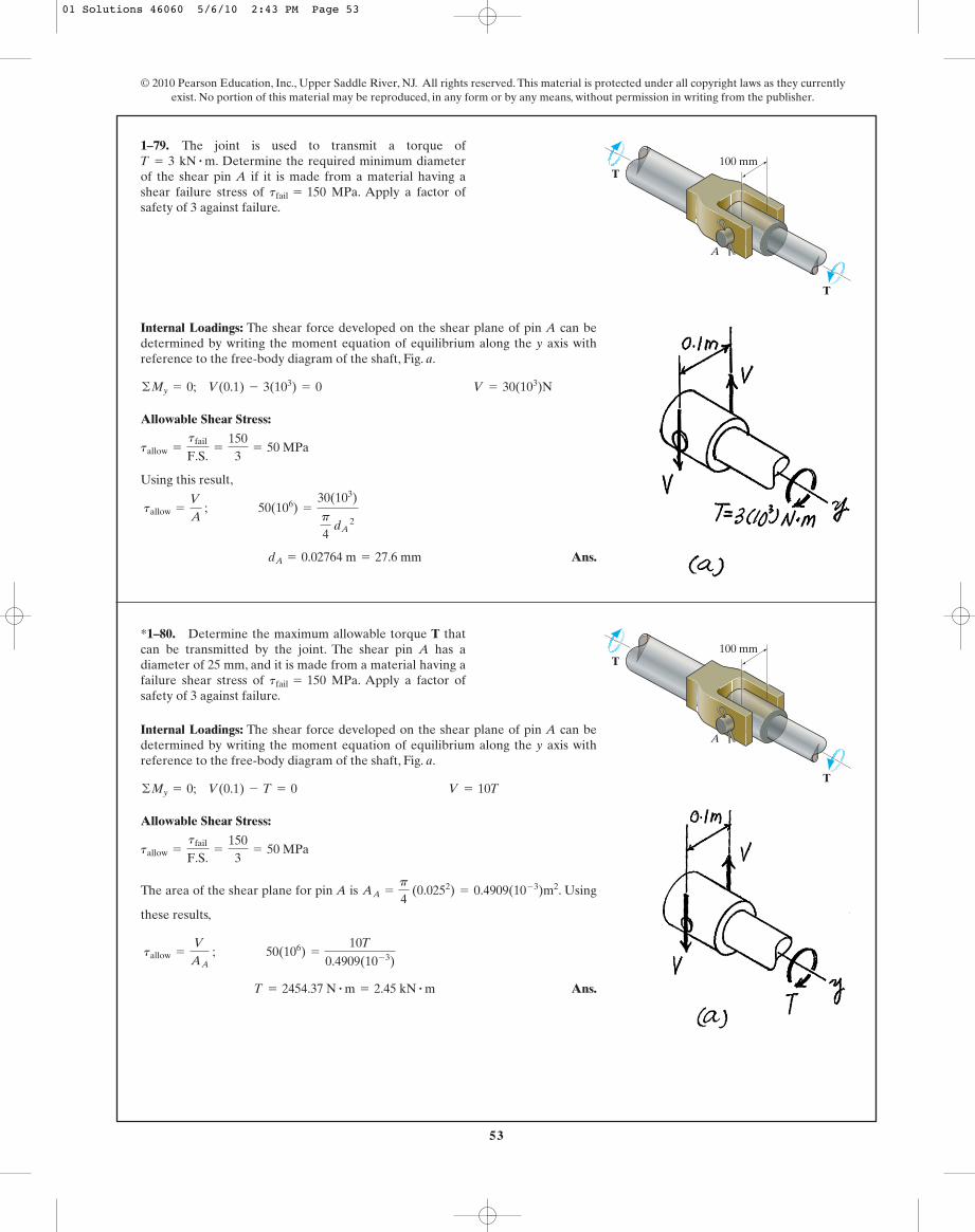
Internal Loadings: The shear force developed on the shear plane of pin A can bedetermined by writing the moment equation of equilibrium along the y axis withreference to the free-body diagram of the shaft, Fig. a.
Allowable Shear Stress:
Using this result,
Ans. dA = 0.02764 m = 27.6 mm
tallow =
V
A ; 50(106) =
30(103)
p
4 dA
2
tallow =
tfail
F.S.=
1503
= 50 MPa
©My = 0; V(0.1) - 3(103) = 0 V = 30(103)N
1–79. The joint is used to transmit a torque of. Determine the required minimum diameter
of the shear pin A if it is made from a material having ashear failure stress of MPa. Apply a factor ofsafety of 3 against failure.
tfail = 150
T = 3 kN # m
A
T
T100 mm
Internal Loadings: The shear force developed on the shear plane of pin A can bedetermined by writing the moment equation of equilibrium along the y axis withreference to the free-body diagram of the shaft, Fig. a.
Allowable Shear Stress:
The area of the shear plane for pin A is . Using
these results,
Ans. T = 2454.37 N # m = 2.45 kN # m
tallow =
V
AA ; 50(106) =
10T
0.4909(10- 3)
AA =
p
4 (0.0252) = 0.4909(10- 3)m2
tallow =
tfail
F.S.=
1503
= 50 MPa
©My = 0; V(0.1) - T = 0 V = 10T
*1–80. Determine the maximum allowable torque T thatcan be transmitted by the joint. The shear pin A has adiameter of 25 mm, and it is made from a material having afailure shear stress of MPa. Apply a factor ofsafety of 3 against failure.
tfail = 150
A
T
T100 mm
01 Solutions 46060 5/6/10 2:43 PM Page 53

54
© 2010 Pearson Education, Inc., Upper Saddle River, NJ. All rights reserved. This material is protected under all copyright laws as they currentlyexist. No portion of this material may be reproduced, in any form or by any means, without permission in writing from the publisher.
(1)
(2)
Assume failure due to shear:
From Eq. (2),
Assume failure due to normal force:
From Eq. (1),
Ans.P = 3.26 kip (controls)
N = 2.827 kip
sallow = 20 =
N
(2) p4 (0.3)2
P = 3.39 kip
V = 1.696 kip
tallow = 12 =
V
(2) p4 (0.3)2
P = 2 V
b+ ©Fx = 0; V - P cos 60° = 0
P = 1.1547 N
a+ ©Fy = 0; N - P sin 60° = 0
•1–81. The tension member is fastened together using twobolts, one on each side of the member as shown. Each bolthas a diameter of 0.3 in. Determine the maximum load Pthat can be applied to the member if the allowable shearstress for the bolts is and the allowableaverage normal stress is .sallow = 20 ksi
tallow = 12 ksi
60�
PP
01 Solutions 46060 5/6/10 2:43 PM Page 54

55
© 2010 Pearson Education, Inc., Upper Saddle River, NJ. All rights reserved. This material is protected under all copyright laws as they currentlyexist. No portion of this material may be reproduced, in any form or by any means, without permission in writing from the publisher.
The force in wire BD is equal to the applied load; ie, . Analysingthe equilibrium of joint B by referring to its FBD, Fig. a,
(1)
(2)
Solving Eqs. (1) and (2),
For wire BD,
Ans.
For wire AB,
Ans.
For wire BC,
Ans. dBC = 6.00 mm
dBC = 0.005822 m = 5.822 mm
sallow =
FBC
ABC ; 165(106) =
4.392(103)p4 dBC
2
Use dAB = 6.50 mm
dAB = 0.006443 m = 6.443 mm
sallow =
FAB
AAB ; 165(106) =
5.379(103)p4 dAB
2
Use dBD = 7.00 mm
dBD = 0.006804 m = 6.804 mm
sallow =
FBD
ABD ; 165(106) =
6(103)p4dBD
2
FAB = 5.379 kN FBC = 4.392 kN
+ c ©Fy = 0; FBC sin 30° + FAB sin 45° - 6 = 0
:+ ©Fx = 0; FBC cos 30° - FAB cos 45° = 0
FBD = P = 6 kN
1–82. The three steel wires are used to support theload. If the wires have an allowable tensile stress of
, determine the required diameter of eachwire if the applied load is .P = 6 kNsallow = 165 MPa
30�45� B
D
P
A
C
01 Solutions 46060 5/6/10 2:43 PM Page 55

56
© 2010 Pearson Education, Inc., Upper Saddle River, NJ. All rights reserved. This material is protected under all copyright laws as they currentlyexist. No portion of this material may be reproduced, in any form or by any means, without permission in writing from the publisher.
The force in wire BD is equal to the applied load; ie, . Analysing theequilibrium of joint B by referring to its FBD, Fig. a,
(1)
(2)
Solving Eqs. (1) and (2),
For wire BD,
For wire AB,
For wire BC,
Ans. P = 4425.60 N = 4.43 kN (Controls!)
sallow =
FBC
ABC ; 165(106) =
0.7321 Pp4 (0.0052)
P = 5203.42 N = 5.203 kN
sallow =
FAB
AAB ; 165(106) =
0.8966 Pp4 (0.0062)
P = 6349.94 N = 6.350 kN
sallow =
FBD
ABD ; 165(106) =
Pp4 (0.0072)
FAB = 0.8966 P FBC = 0.7321 P
+ c ©Fy = 0; FBC sin 30° + FAB sin 45° - P = 0
:+ ©Fx = 0; FBC cos 30° - FAB cos 45° = 0
FBD = P
1–83. The three steel wires are used to support theload. If the wires have an allowable tensile stress of
, and wire AB has a diameter of 6 mm, BChas a diameter of 5 mm, and BD has a diameter of 7 mm,determine the greatest force P that can be applied beforeone of the wires fails.
sallow = 165 MPa
30�45� B
D
P
A
C
01 Solutions 46060 5/6/10 2:43 PM Page 56

57
© 2010 Pearson Education, Inc., Upper Saddle River, NJ. All rights reserved. This material is protected under all copyright laws as they currentlyexist. No portion of this material may be reproduced, in any form or by any means, without permission in writing from the publisher.
Solution
Allowable Bearing Stress: Assume bearing failure for disk B.
Allowable Shear Stress: Assume shear failure for disk C.
Ans.
Allowable Bearing Stress: Assume bearing failure for disk C.
Ans.
Since , disk B might fail due to shear.
Therefore, Ans.d1 = 22.6 mm
t =
V
A=
140(103)
p(0.02257)(0.02)= 98.7 MPa 6 tallow = 125 MPa (O. K !)
d3 = 27.6 mm 7 d1 = 22.6 mm
d3 = 0.02760 m = 27.6 mm
(sb)allow =
P
A ; 350 A106 B =
140(103)p4 A0.035652
- d32 B
d2 = 0.03565 m = 35.7 mm
tallow =
V
A ; 125 A106 B =
140(103)
pd2 (0.01)
d1 = 0.02257 m = 22.6 mm
(sb)allow =
P
A ; 350 A106 B =
140(103)p4 d1
2
*1–84. The assembly consists of three disks A, B, and Cthat are used to support the load of 140 kN. Determine thesmallest diameter of the top disk, the diameter withinthe support space, and the diameter of the hole in thebottom disk. The allowable bearing stress for the materialis and allowable shear stress istallow = 125 MPa.1sallow2b = 350 MPa
d3
d2d110 mm
20 mm
140 kN
d2
d3
d1
AB
C
Ans.
FAB = 1442.9 lb
W = 431 lb
+ c ©Fy = 0; -W + FAB cos 45° - 1178.10 sin 30° = 0
:+ ©Fx = 0; -1178.10 cos 30° + FAB sin 45° = 0
T = 1178.10 lb
s =
P
A ; 24(103) =
Tp4 (0.25)2;
•1–85. The boom is supported by the winch cable that hasa diameter of 0.25 in. and an allowable normal stress of
Determine the greatest load that can besupported without causing the cable to fail when and Neglect the size of the winch.f = 45°.
u = 30°sallow = 24 ksi.
20 ft
f
u
A
B
d
01 Solutions 46060 5/6/10 2:43 PM Page 57

58
Maximum tension in cable occurs when .
Ans.Use d = 1 1
16 in.
d = 1.048 in.
s =
P
A ; 24(103) =
20 698.3p4 (d)2
FAB = 22 896 lb
T = 20 698.3 lb
+ c ©Fy = 0; FAB sin 31.842° - T sin 20° - 5000 = 0
:+ © Fx = 0; -T cos 20° + FAB cos 31.842° = 0
c = 11.842°
sin 20°
20=
sin c
12
u = 20°
1–86. The boom is supported by the winch cable that hasan allowable normal stress of If it isrequired that it be able to slowly lift 5000 lb, from to determine the smallest diameter of the cable tothe nearest The boom AB has a length of 20 ft.Neglect the size of the winch. Set d = 12 ft.
116 in.
u = 50°,u = 20°
sallow = 24 ksi.
© 2010 Pearson Education, Inc., Upper Saddle River, NJ. All rights reserved. This material is protected under all copyright laws as they currentlyexist. No portion of this material may be reproduced, in any form or by any means, without permission in writing from the publisher.
20 ft
f
u
A
B
d
For failure of pine block:
Ans.
For failure of oak post:
Area of plate based on strength of pine block:
Ans.
Ans. Pmax = 155 kN
A = 6.19(10- 3)m2
s =
P
A; 25(106) =
154.8(10)3
A
P = 154.8 kN
s =
P
A; 43(106) =
P
(0.06)(0.06)
P = 90 kN
s =
P
A; 25(106) =
P
(0.06)(0.06)
1–87. The oak post is supported onthe pine block. If the allowable bearing stresses forthese materials are and ,determine the greatest load P that can be supported. Ifa rigid bearing plate is used between these materials,determine its required area so that the maximum load P canbe supported. What is this load?
spine = 25 MPasoak = 43 MPa
60 mm * 60 mm P
01 Solutions 46060 5/6/10 2:43 PM Page 58

59
© 2010 Pearson Education, Inc., Upper Saddle River, NJ. All rights reserved. This material is protected under all copyright laws as they currentlyexist. No portion of this material may be reproduced, in any form or by any means, without permission in writing from the publisher.
*1–88. The frame is subjected to the load of 4 kN whichacts on member ABD at D. Determine the requireddiameter of the pins at D and C if the allowable shear stressfor the material is Pin C is subjected todouble shear, whereas pin D is subjected to single shear.
tallow = 40 MPa.
B
1.5 m
4 kN
45� 1.5 m1 m
1.5 m
DCE
A
Referring to the FBD of member DCE, Fig. a,
a (1)
(2)
Referring to the FBD of member ABD, Fig. b,
a (3)
Solving Eqs (2) and (3),
Substitute the result of into (1)
Thus, the force acting on pin D is
Pin C is subjected to double shear white pin D is subjected to single shear. Referringto the FBDs of pins C, and D in Fig c and d, respectively,
For pin C,
Ans.
For pin D,
Ans. Use dD = 14 mm
dD = 0.01393 m = 13.93 mm
tallow =
VD
AD; 40(106) =
6.093(103)p4 dD
2
Use dC = 12 mm
dC = 0.01128 m = 11.28 mm
tallow =
VC
AC; 40(106) =
4.00(103)p4 dC
2
VC =
FBC
2=
8.002
= 4.00 kN VD = FD = 6.093 kN
FD = 2 Dx 2
+ Dy 2
= 2 5.6572+ 2.2632
= 6.093 kN
Dy = 2.263 kN
FBC
FBC = 8.00 kN Dx = 5.657 kN
+ ©MA = 0; 4 cos 45° (3) + FBC sin 45° (1.5) - Dx (3) = 0
:+ ©Fx = 0 FBC cos 45° - Dx = 0
+ ©ME = 0; Dy(2.5) - FBC sin 45° (1) = 0
01 Solutions 46060 5/6/10 2:43 PM Page 59

60
© 2010 Pearson Education, Inc., Upper Saddle River, NJ. All rights reserved. This material is protected under all copyright laws as they currentlyexist. No portion of this material may be reproduced, in any form or by any means, without permission in writing from the publisher.
Allowable Normal Stress: Design of bolt size
Ans.
Allowable Shear Stress: Design of support thickness
Ans. Use h =
38
in.
tallow =
V
A ; 5(103) =
5(103)
p(1)(h)
Use d =
58
in.
d = 0.5506 in.
sallow =
P
Ab ; 21.0(103) =
5(103)p4 d2
•1–89. The eye bolt is used to support the load of 5 kip.Determine its diameter d to the nearest and the requiredthickness h to the nearest of the support so that thewasher will not penetrate or shear through it. The allowablenormal stress for the bolt is and the allowableshear stress for the supporting material is tallow = 5 ksi.
sallow = 21 ksi
18 in.
18 in.
1 in.
d
5 kip
h
01 Solutions 46060 5/6/10 2:43 PM Page 60

61
© 2010 Pearson Education, Inc., Upper Saddle River, NJ. All rights reserved. This material is protected under all copyright laws as they currentlyexist. No portion of this material may be reproduced, in any form or by any means, without permission in writing from the publisher.
Internal Loadings: The forces acting on pins B and C can be determined byconsidering the equilibrium of the free-body diagram of the soft-ride suspensionsystem shown in Fig. a.
a
Thus,
Since both pins are in double shear,
Allowable Shear Stress:
Using this result,
Ans.
Ans. dC = 0.006294 m = 6.29 mm
tallow =
VC
AC; 75(106) =
2333.49p
4 dC
2
dB = 0.007080 m = 7.08 mm
tallow =
VB
AB ; 75(106) =
2952.68p
4 dB
2
tallow =
tfail
F.S.=
1502
= 75 MPa
VB =
FB
2=
5905.362
= 2952.68 N VC =
FC
2=
4666.982
= 2333.49 N
= 4666.98 N
FB = FBD = 5905.36 N FC = 2 Cx 2
+ Cy 2
= 2 2952.682+ 3614.202
+ c ©Fy = 0; 5905.36 sin 60° - 1500 - Cy = 0 Cy = 3614.20 N
:+ ©Fx = 0; Cx - 5905.36 cos 60° = 0 Cx = 2952.68 N
FBD = 5905.36 N
+ ©MC = 0; 1500(0.4) - FBD sin 60°(0.1) - FBD cos 60°(0.03) = 0
1–90. The soft-ride suspension system of the mountainbike is pinned at C and supported by the shock absorberBD. If it is designed to support a load ,determine the required minimum diameter of pins B and C.Use a factor of safety of 2 against failure. The pins are madeof material having a failure shear stress of ,and each pin is subjected to double shear.
tfail = 150 MPa
P = 1500 N
CB
D
A
P
300 mm100 mm
30 mm
60�
01 Solutions 46060 5/6/10 2:43 PM Page 61

62
© 2010 Pearson Education, Inc., Upper Saddle River, NJ. All rights reserved. This material is protected under all copyright laws as they currentlyexist. No portion of this material may be reproduced, in any form or by any means, without permission in writing from the publisher.
Internal Loadings: The forces acting on pins B and C can be determined byconsiderning the equilibrium of the free-body diagram of the soft-ride suspensionsystem shown in Fig. a.
Thus,
Since both pins are in double shear,
Allowable Shear Stress: The areas of the shear plane for pins B and C are
and .
We obtain
Using these results,
Ans.
Ans.(F.S.)C =
tfail
Atavg BC=
15070.32
= 2.13
(F.S.)B =
tfail
Atavg BB=
15066.84
= 2.24
Atavg BC =
VC
AC=
2333.49
33.183(10- 6)= 70.32 MPa
Atavg BB =
VB
AB=
2952.68
44.179(10- 6)= 66.84 MPa
AC =
p
4 (0.00652) = 33.183(10- 6)m2AB =
p
4 (0.00752) = 44.179(10- 6)m2
VB =
FB
2=
5905.362
= 2952.68N VC =
FC
2=
4666.982
= 2333.49 N
= 4666.98 N
FB = FBD = 5905.36 N FC = 2 Cx 2
+ Cy 2
= 2 2952.682+ 3614.202
+ c ©Fy = 0; 5905.36 sin 60° - 1500 - Cy = 0 Cy = 3614.20 N
:+ ©Fx = 0; Cx - 5905.36 cos 60° = 0 Cx = 2952.68 N
FBD = 5905.36 N
+ ©MC = 0; 1500(0.4) - FBD sin 60°(0.1) - FBD cos 60°(0.03) = 0
1–91. The soft-ride suspension system of the mountainbike is pinned at C and supported by the shock absorberBD. If it is designed to support a load of ,determine the factor of safety of pins B and C againstfailure if they are made of a material having a shear failurestress of . Pin B has a diameter of 7.5 mm,and pin C has a diameter of 6.5 mm. Both pins are subjectedto double shear.
tfail = 150 MPa
P = 1500 N
CB
D
A
P
300 mm100 mm
30 mm
60�
01 Solutions 46060 5/6/10 2:43 PM Page 62

63
© 2010 Pearson Education, Inc., Upper Saddle River, NJ. All rights reserved. This material is protected under all copyright laws as they currentlyexist. No portion of this material may be reproduced, in any form or by any means, without permission in writing from the publisher.
From FBD (a):
a
(1)
From FBD (b):
a
(2)
Solving Eqs. (1) and (2) yields
For bolt:
Ans.
For washer:
Ans.dw = 0.0154 m = 15.4 mm
sallow = 28 (104) =
4.40(103)p4 (d2
w - 0.006112)
= 6.11 mm
dB = 0.00611 m
sallow = 150(106) =
4.40(103)p4 (dB)2
FB = 4.40 kN; FC = 4.55 kN
5.5 FB - 4 FC = 6
+ ©MD = 0; FB(5.5) - FC(4) - 3(2) = 0
4.5 FB - 6 FC = -7.5
+ ©MD = 0; FB(4.5) + 1.5(3) + 2(1.5) - FC(6) = 0
*1–92. The compound wooden beam is connected togetherby a bolt at B.Assuming that the connections at A, B, C, andD exert only vertical forces on the beam, determine therequired diameter of the bolt at B and the required outerdiameter of its washers if the allowable tensile stress for thebolt is and the allowable bearing stressfor the wood is Assume that the hole inthe washers has the same diameter as the bolt.
1sb2allow = 28 MPa.1st2allow = 150 MPa
1.5 m1.5 m1.5 m1.5 m2 m2 m
B
C DA
3 kN 1.5 kN2 kN
For rod BC:
Ans.
For pins B and C:
Ans. F. S. =
ty
t=
1811.79
= 1.53
t =
V
A=
0.8333p4 (0.32)
= 11.79 ksi
F. S. =
sy
s=
3613.26
= 2.71
s =
P
A=
1.667p4 (0.42)
= 13.26 ksi
•1–93. The assembly is used to support the distributedloading of . Determine the factor of safety withrespect to yielding for the steel rod BC and the pins at B andC if the yield stress for the steel in tension is and in shear . The rod has a diameter of 0.40 in.,and the pins each have a diameter of 0.30 in.
ty = 18 ksisy = 36 ksi
w = 500 lb>ft C
B
A
4 ft
3 ft
1 ft
w
01 Solutions 46060 5/6/10 2:43 PM Page 63

64
Assume failure of pins B and C:
Ans.
Assume failure of pins A:
Assume failure of rod BC:
w = 0.829 kip>ft
sallow = 22 =
3.333wp4 (0.42)
w = 0.735 kip>ft
tallow = 12.5 =
1.202wp4 (0.32)
FA = 2 (2w)2+ (1.333w)2
= 2.404 w
w = 0.530 kip>ft (controls)
tallow = 12.5 =
1.667wp4 (0.32)
1–94. If the allowable shear stress for each of the 0.30- in.-diameter steel pins at A, B, and C is ,and the allowable normal stress for the 0.40-in.-diameterrod is , determine the largest intensity w ofthe uniform distributed load that can be suspended fromthe beam.
sallow = 22 ksi
tallow = 12.5 ksi
© 2010 Pearson Education, Inc., Upper Saddle River, NJ. All rights reserved. This material is protected under all copyright laws as they currentlyexist. No portion of this material may be reproduced, in any form or by any means, without permission in writing from the publisher.
C
B
A
4 ft
3 ft
1 ft
w
Referring to the FBD of the bean, Fig. a
a
a
For plate ,
Ans.
For plate ,
Ans. aB¿= 0.300 m = 300 mm
sallow =
NB
AB¿
; 1.5(106) =
135(103)
a2B¿
B¿
aA¿= 0.1291 m = 130 mm
(sb)allow =
NA
AA¿
; 1.5(106) =
25.0(103)
a2A¿
A¿
+ ©MB = 0; 40(1.5)(3.75) - 100(1.5) - NA(3) = 0 NA = 25.0 kN
+ ©MA = 0; NB(3) + 40(1.5)(0.75) - 100(4.5) = 0 NB = 135 kN
1–95. If the allowable bearing stress for the materialunder the supports at A and B is determine the size of square bearing plates and required to support the load. Dimension the plates to thenearest mm.The reactions at the supports are vertical.TakeP = 100 kN.
B¿A¿
1sb2allow = 1.5 MPa,
3 m
P
A¿ B¿A B
40 kN/m
1.5 m 1.5 m
01 Solutions 46060 5/6/10 2:43 PM Page 64

65
© 2010 Pearson Education, Inc., Upper Saddle River, NJ. All rights reserved. This material is protected under all copyright laws as they currentlyexist. No portion of this material may be reproduced, in any form or by any means, without permission in writing from the publisher.
*1–96. If the allowable bearing stress for the material underthe supports at A and B is determinethe maximum load P that can be applied to the beam. Thebearing plates and have square cross sections of
and respectively.250 mm * 250 mm,150 mm * 150 mmB¿A¿
1sb2allow = 1.5 MPa,
3 m
P
A¿ B¿A B
40 kN/m
1.5 m 1.5 m
Referring to the FBD of the beam, Fig. a,
a
a
For plate ,
For plate ,
Ans. P = 72.5 kN (Controls!)
(sb)allow =
NB
AB¿
; 1.5(106) =
(1.5P - 15)(103)
0.25(0.25)
B¿
P = 82.5 kN
(sb)allow =
NA
AA¿
; 1.5(106) =
(75 - 0.5P)(103)
0.15(0.15)
A¿
+ ©MB = 0; 40(1.5)(3.75) - P(1.5) - NA(3) = 0 NA = 75 - 0.5P
+ ©MA = 0; NB(3) + 40(1.5)(0.75) - P(4.5) = 0 NB = 1.5P - 15
Support Reactions:
a
a
Allowable Normal Stress: Design of rod sizes
For rod AB
Ans.
For rod CD
Ans. dCD = 0.005410 m = 5.41 mm
sallow =
sfail
F.S=
FCD
ACD ; 510(106)
1.75=
6.70(103)p4 d2
CD
dAB = 0.006022 m = 6.02 mm
sallow =
sfail
F.S=
FAB
AAB ; 510(106)
1.75=
8.30(103)p4 d2
AB
FAB = 8.30 kN
+ ©MC = 0; 4(8) + 6(6) + 5(3) - FAB(10) = 0
FCD = 6.70 kN
+ ©MA = 0; FCD(10) - 5(7) - 6(4) - 4(2) = 0
•1–97. The rods AB and CD are made of steel having afailure tensile stress of Using a factor ofsafety of for tension, determine their smallestdiameter so that they can support the load shown. Thebeam is assumed to be pin connected at A and C.
F.S. = 1.75sfail = 510 MPa.
B
A
D
C
4 kN
6 kN5 kN
3 m2 m2 m 3 m
01 Solutions 46060 5/6/10 2:43 PM Page 65

66
Equation of Equilibrium:
Allowable Shear Stress: Design of the support size
Ans. h = 1.74 in.
tallow =
tfail
F.S=
V
A ; 23(103)
2.5=
8.00(103)
h(0.5)
+ c ©Fy = 0; V - 8 = 0 V = 8.00 kip
1–98. The aluminum bracket A is used to support thecentrally applied load of 8 kip. If it has a constant thicknessof 0.5 in., determine the smallest height h in order toprevent a shear failure. The failure shear stress is
Use a factor of safety for shear of F.S. = 2.5.tfail = 23 ksi.
© 2010 Pearson Education, Inc., Upper Saddle River, NJ. All rights reserved. This material is protected under all copyright laws as they currentlyexist. No portion of this material may be reproduced, in any form or by any means, without permission in writing from the publisher.
8 kip
hA
Allowable Normal Stress: For the hanger
Allowable Shear Stress: The pin is subjected to double shear. Therefore,
Allowable Bearing Stress: For the bearing area
Ans. P = 55.0 kN (Controls!)
(sb)allow =
P
A ; 220 A106 B =
P>2
(0.005)(0.025)
P = 65.0 kN
tallow =
V
A ; 130 A106 B =
P>2
(0.01)(0.025)
V =
P
2
P = 67.5 kN
(st)allow =
P
A ; 150 A106 B =
P
(0.075)(0.006)
1–99. The hanger is supported using the rectangular pin.Determine the magnitude of the allowable suspended loadP if the allowable bearing stress is MPa, theallowable tensile stress is MPa, and theallowable shear stress is Take
and b = 25 mm.a = 5 mm,t = 6 mm,tallow = 130 MPa.
(st)allow = 150(sb)allow = 220
20 mm
75 mm
10 mm
aa b
tP
37.5 mm
37.5 mm
01 Solutions 46060 5/6/10 2:43 PM Page 66

67
© 2010 Pearson Education, Inc., Upper Saddle River, NJ. All rights reserved. This material is protected under all copyright laws as they currentlyexist. No portion of this material may be reproduced, in any form or by any means, without permission in writing from the publisher.
Allowable Normal Stress: For the hanger
Ans.
Allowable Shear Stress: For the pin
Ans.
Allowable Bearing Stress: For the bearing area
Ans. a = 0.00431 m = 4.31 mm
(sb)allow =
P
A ; 290 A106 B =
30(103)
(0.0240) a
b = 0.0240 m = 24.0 mm
tallow =
V
A ; 125 A106 B =
30(103)
(0.01)b
t = 0.005333 m = 5.33 mm
(st)allow =
P
A; 150 A106 B =
60(103)
(0.075)t
*1–100. The hanger is supported using the rectangularpin. Determine the required thickness t of the hanger, anddimensions a and b if the suspended load is The allowable tensile stress is theallowable bearing stress is and theallowable shear stress is tallow = 125 MPa.
(sb)allow = 290 MPa,(st)allow = 150 MPa,
P = 60 kN.
20 mm
75 mm
10 mm
aa b
tP
37.5 mm
37.5 mm
01 Solutions 46060 5/6/10 2:43 PM Page 67

68
© 2010 Pearson Education, Inc., Upper Saddle River, NJ. All rights reserved. This material is protected under all copyright laws as they currentlyexist. No portion of this material may be reproduced, in any form or by any means, without permission in writing from the publisher.
Referring to the FBD of the upper segment of the cylinder sectional through a–ashown in Fig. a,
Section a–a of the cylinder is an ellipse with and . Thus,
.
Ans.
Ans.
The differential element representing the state of stress of a point on section a–a isshown in Fig. b
Ata - a Bavg =
Va - a
Aa - a=
150(103)
0.03628= 4.135(106) Pa = 4.13 MPa
Asa - a Bavg =
Na - a
Aa - a=
259.81(103)
0.03628= 7.162(106) Pa = 7.16 MPa
Aa - a = pab = p(0.1)a0.1
cos 30°b = 0.03628 m2
b =
0.1cos 30°
ma = 0.1 m
+a©Fy¿= 0; Va - a - 300 sin 30° = 0 Va - a = 150 kN
+Q©Fx¿= 0; Na - a - 300 cos 30° = 0 Na - a = 259.81 kN
•1–101. The 200-mm-diameter aluminum cylinder supportsa compressive load of 300 kN. Determine the average normaland shear stress acting on section a–a. Show the results on adifferential element located on the section.
30�
300 kN
a
d
a
Ans.
Ans.
Ans.(tavg)b =
V
A=
8 (103)
p (0.007)(0.008)= 45.5 MPa
(tavg)a =
V
A=
8 (103)
p (0.018)(0.030)= 4.72 MPa
ss =
P
A=
8 (103)p4 (0.007)2 = 208 MPa
1–102. The long bolt passes through the 30-mm-thickplate. If the force in the bolt shank is 8 kN, determine theaverage normal stress in the shank, the average shear stressalong the cylindrical area of the plate defined by the sectionlines a–a, and the average shear stress in the bolt head alongthe cylindrical area defined by the section lines b–b.
8 kN18 mm
7 mm
30 mm
8 mm a
a
b
b
01 Solutions 46060 5/6/10 2:43 PM Page 68
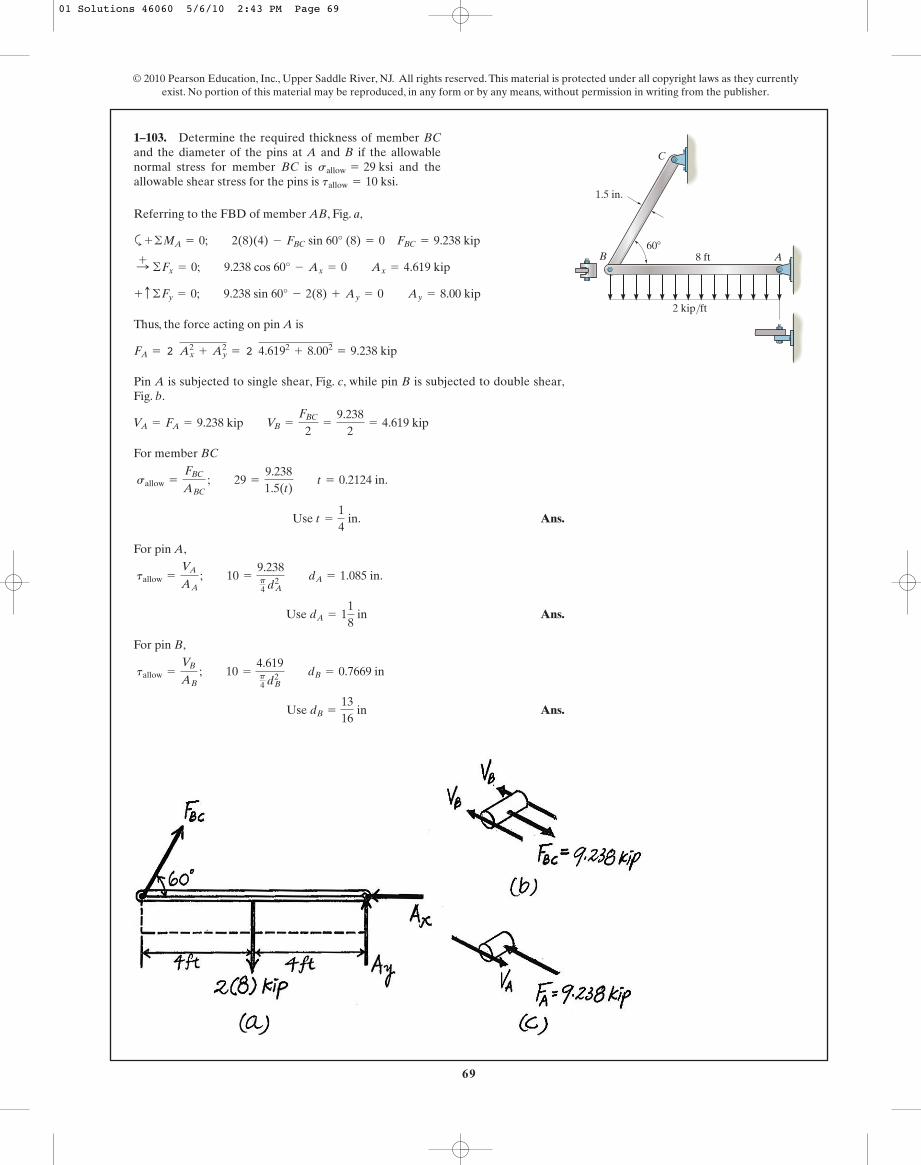
69
Referring to the FBD of member AB, Fig. a,
a
Thus, the force acting on pin A is
Pin A is subjected to single shear, Fig. c, while pin B is subjected to double shear,Fig. b.
For member BC
Ans.
For pin A,
Ans.
For pin B,
Ans. Use dB =
1316
in
tallow =
VB
AB ; 10 =
4.619p4 dB
2 dB = 0.7669 in
Use dA = 118
in
tallow =
VA
AA ; 10 =
9.238p4 d2
A dA = 1.085 in.
Use t =
14
in.
sallow =
FBC
ABC ; 29 =
9.2381.5(t) t = 0.2124 in.
VA = FA = 9.238 kip VB =
FBC
2=
9.2382
= 4.619 kip
FA = 2 Ax2
+ Ay2
= 2 4.6192+ 8.002
= 9.238 kip
+ c ©Fy = 0; 9.238 sin 60° - 2(8) + Ay = 0 Ay = 8.00 kip
:+ ©Fx = 0; 9.238 cos 60° - Ax = 0 Ax = 4.619 kip
+ ©MA = 0; 2(8)(4) - FBC sin 60° (8) = 0 FBC = 9.238 kip
1–103. Determine the required thickness of member BCand the diameter of the pins at A and B if the allowablenormal stress for member BC is and theallowable shear stress for the pins is tallow = 10 ksi.
sallow = 29 ksi
© 2010 Pearson Education, Inc., Upper Saddle River, NJ. All rights reserved. This material is protected under all copyright laws as they currentlyexist. No portion of this material may be reproduced, in any form or by any means, without permission in writing from the publisher.
C
60�8 ftB A
2 kip/ft
1.5 in.
01 Solutions 46060 5/6/10 2:43 PM Page 69

70
Segment AD:
Ans.
Ans.
a
Ans.
Segment CE:
Ans.
Ans.
a Ans.+ ©ME = 0; ME = 0
R+ ©Fy = 0; VE = 0
Q+ ©Fx = 0; NE + 2.0 = 0; NE = -2.00 kip
MD = -0.769 kip # ft
+ ©MD = 0; MD + 0.225(0.75) + 0.4(1.5) = 0
+ T ©Fy = 0; VD + 0.225 + 0.4 = 0; VD = -0.625 kip
:+
©Fx = 0; ND - 1.2 = 0; ND = 1.20 kip
*1–104. Determine the resultant internal loadings acting onthe cross sections located through points D and E of the frame.
© 2010 Pearson Education, Inc., Upper Saddle River, NJ. All rights reserved. This material is protected under all copyright laws as they currentlyexist. No portion of this material may be reproduced, in any form or by any means, without permission in writing from the publisher.
4 ft
1.5 ftA
D
5 ft3 ftC
2.5 ft
E
B
150 lb/ft
a
Ans.tavg =
V
A=
3678.75(0.005)(0.012)
= 61.3 MPa
F = 3678.75 N
+ ©MO = 0; F (10) - 490.5 (75) = 0
•1–105. The pulley is held fixed to the 20-mm-diametershaft using a key that fits within a groove cut into the pulleyand shaft. If the suspended load has a mass of 50 kg,determine the average shear stress in the key along sectiona–a. The key is 5 mm by 5 mm square and 12 mm long. 75 mm
a a
01 Solutions 46060 5/6/10 2:43 PM Page 70

71
© 2010 Pearson Education, Inc., Upper Saddle River, NJ. All rights reserved. This material is protected under all copyright laws as they currentlyexist. No portion of this material may be reproduced, in any form or by any means, without permission in writing from the publisher.
Equation of Equilibrium:
Averge Normal Stress And Shear Stress: The cross sectional Area at section a–a is
.
Ans.
Ans.ta - a =
Va - a
A=
3.00(103)
0.02598= 115 kPa
sa - a =
Na - a
A=
5.196(103)
0.02598= 200 kPa
A = a0.15
sin 60°b(0.15) = 0.02598 m2
a+ ©Fy = 0; Na - a - 6 sin 60° = 0 Na - a = 5.196 kN
+Q©Fx = 0; Va - a - 6 cos 60° = 0 Va - a = 3.00 kN
1–106. The bearing pad consists of a 150 mm by 150 mmblock of aluminum that supports a compressive load of6 kN. Determine the average normal and shear stress actingon the plane through section a–a. Show the results on adifferential volume element located on the plane.
30�
150 mm
6 kN
a
a
For the 40 – mm – dia rod:
Ans.
For the 30 – mm – dia rod:
Ans.
Average shear stress for pin A:
Ans.tavg =
P
A=
2.5 (103)p4 (0.025)2 = 5.09 MPa
s30 =
V
A=
5 (103)p4 (0.03)2 = 7.07 MPa
s40 =
P
A=
5 (103)p4 (0.04)2 = 3.98 MPa
1–107. The yoke-and-rod connection is subjected to atensile force of 5 kN. Determine the average normal stressin each rod and the average shear stress in the pin Abetween the members.
25 mm
40 mm
30 mm
A
5 kN
5 kN
01 Solutions 46060 5/6/10 2:43 PM Page 71

72
Equation of Equilibrium:
a
Average Normal Stress:
Ans.s =
T
A=
gAL2
8 s
A=
gL2
8 s
T =
gAL2
8 s
+ ©MA = 0; Ts -
gAL
2 a
L
4b = 0
*1–108. The cable has a specific weight and cross-sectional area A. If the sag s is small, so that itslength is approximately L and its weight can be distributeduniformly along the horizontal axis, determine the averagenormal stress in the cable at its lowest point C.
(weight>volume)g
© 2010 Pearson Education, Inc., Upper Saddle River, NJ. All rights reserved. This material is protected under all copyright laws as they currentlyexist. No portion of this material may be reproduced, in any form or by any means, without permission in writing from the publisher.
s
L/2 L/2
C
A B
01 Solutions 46060 5/6/10 2:43 PM Page 72