08tkm366lect8 force torqu strain
DESCRIPTION
klnlnln ljjjjjjjjjjjjjjjjjj jjjjjjjjjjjjjjjjjjjjjjjjjjjjjjjjjjjjjjjjjjjjjjjjjjjjjjjjjjjjjjj jjjjjjjjjjjjjjjjjjjjjjjjjjjjj jjjjjjjjjj jjjjjjjjjjjjjjjjjjTRANSCRIPT

Force, Torque & Strain Measurement
Teknik Pengukuran
Universitas Diponegoro 2011 TKM328 Teknik Pengukuran 2
Presentation Overview Strain gages Load cell Wheatstone bridge circuit Torque cell
Universitas Diponegoro 2011 TKM328 Teknik Pengukuran 3
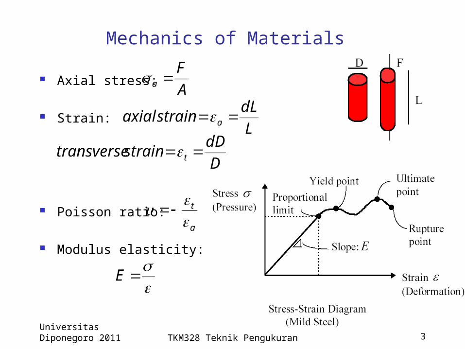
Mechanics of Materials Axial stress:
Strain:
Poisson ratio:
Modulus elasticity:
LdLstrainaxial a
DdDstraintransverse t
AF
a
a
t
E
Universitas Diponegoro 2011 TKM328 Teknik Pengukuran 4
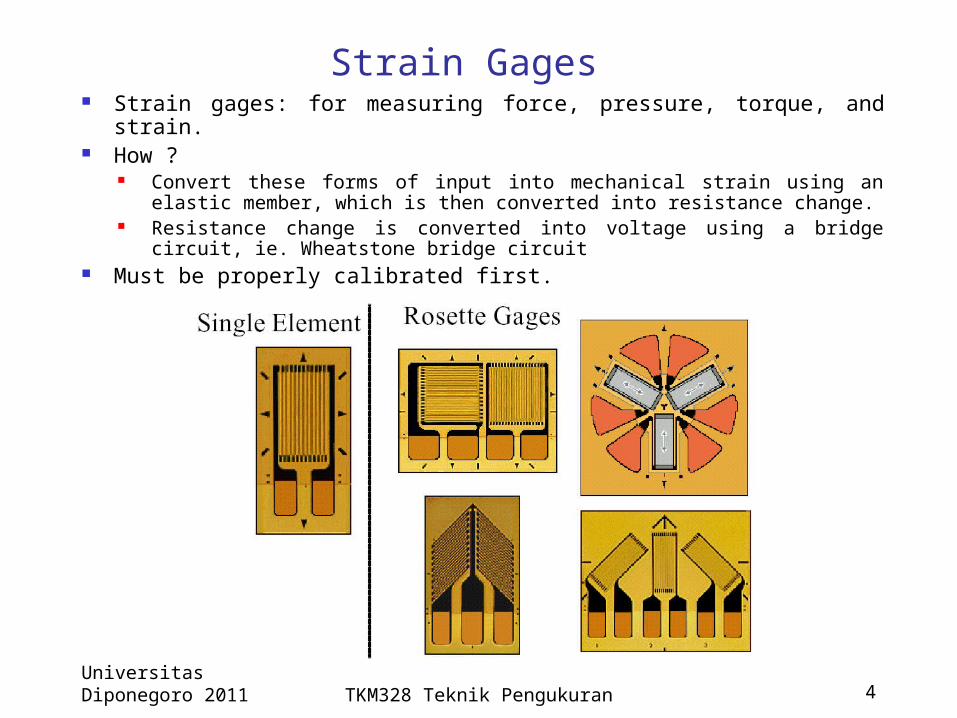
Strain Gages Strain gages: for measuring force, pressure, torque, and strain. How ?
Convert these forms of input into mechanical strain using an elastic member, which is then converted into resistance change.
Resistance change is converted into voltage using a bridge circuit, ie. Wheatstone bridge circuit
Must be properly calibrated first.
Universitas Diponegoro 2011 TKM328 Teknik Pengukuran 5
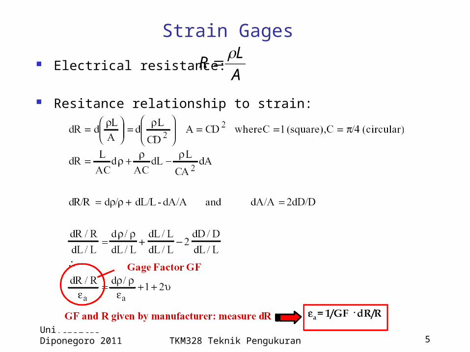
Strain Gages Electrical resistance:
Resitance relationship to strain:
ALR

Universitas Diponegoro 2011 TKM328 Teknik Pengukuran 6
Strain Gages: Calculation Example

Universitas Diponegoro 2011 TKM328 Teknik Pengukuran 7
Strain Gages: Calculation Example
Universitas Diponegoro 2011 TKM328 Teknik Pengukuran 8
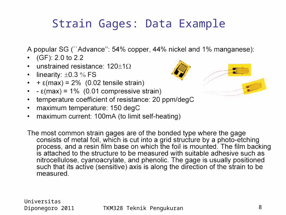
Strain Gages: Data Example

Universitas Diponegoro 2011 TKM328 Teknik Pengukuran 9
Strain Gages Typical Values Electrical Resistance, R 120 Ohm or 350 Ohm 1000 Ohm with plastic materials
A high Gage Factor is desirable because a large change in R is produced for a given strain Metal GF= 1.6 to 4 Resistivity does not change with the strain
Semiconductor GF= 80 to 200 Fragile and sensitive to changes in temperature
Axial strain range = 10-6 to 103
dR=0.00024 Ohm to 0.24 Ohm Notice how small this dR Need to utilize Wheatstone bridge circuit

Universitas Diponegoro 2011 TKM328 Teknik Pengukuran 10
Strain Gages: Gage Factor Table
Most GF decreases as temperature increase (NTC)

Universitas Diponegoro 2011 TKM328 Teknik Pengukuran 11
Strain Gages Calibration A measurement instrument
must be calibrated by applying the inputs of known values (standards) and measuring its output.
It involves a comparison of the instrument with a higher standard and, thus, reduces bias errors.
Once this relationship is established or verified, the input values can be inferred from the measured values (often voltage) accurately.
Force (F=mg)(Standard brass-weight)
Load Cell(Cantilever Beam)
SGBridge Circuit +Power Source
OutputVoltage
Force Load Cell Strain Gage(s) Bridge Circuit
Voltage
ExcitationVoltage
The voltage vs force relationshipmust be determined experimentally.(Calibration)
Voltage
Force
Universitas Diponegoro 2011 TKM328 Teknik Pengukuran 12
Load Cell
Transducers which measure force, torque, or pressure usually contain an elastic member that converts the mechanical quantity into a deflection or strain.
Load cell= elastic members employed in these transducers include link, column, rings, beams, cylinders, tubes, washers, diaphragms, etc.
Two main types of load cell Bending-beam load-cell and Axial load-cell.

Universitas Diponegoro 2011 TKM328 Teknik Pengukuran 13
Load Cell: Bending Beam The most popular types
due to its simple design and low cost. To measure an applied force F, strain gages are mounted on the beam.
F H b l L
Support
Beam
F
EbhL
material ofproperty
beamofgeometry
2
locationSGat
16

Universitas Diponegoro 2011 TKM328 Teknik Pengukuran 14
Load Cell: Axial
F
Ebh
material ofproperty
beamofgeometry
11
h F b

Universitas Diponegoro 2011 TKM328 Teknik Pengukuran 15
Strain Gages Selection Gage selections based on
Alloy selection, number of gages, gage length, gage width, solder tab type, gage pattern, temperature compensation, grid resistance, accuracy, stability, cyclic endurance, operating environment and installation requirements
Transverse sensitivity Smaller Kt is desirable
a
tt GF
GFK
Universitas Diponegoro 2011 TKM328 Teknik Pengukuran 16
Potential Error Sources with Strain Gages Application errors:
Gage may be damaged during installation Need to verify resistance before stress
Electrical and magnetic field noise Uneed shielded lead wires and insulated coatings Utilize twisted lead wires
Temperature effects Thermal expansion of material Self heating of strain gages
Universitas Diponegoro 2011 TKM328 Teknik Pengukuran 17
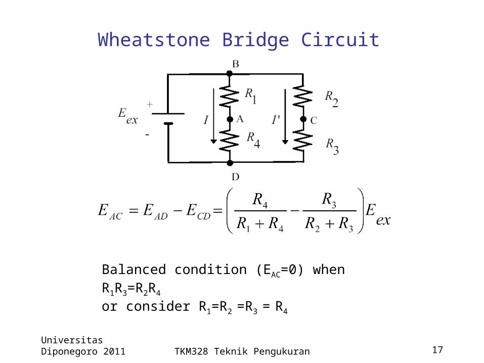
Wheatstone Bridge Circuit
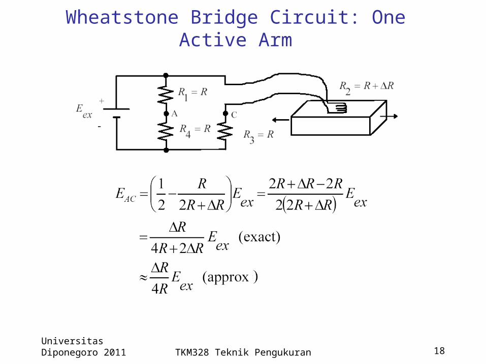
Balanced condition (EAC=0) when R1R3=R2R4or consider R1=R2 =R3 = R4
Universitas Diponegoro 2011 TKM328 Teknik Pengukuran 18
Wheatstone Bridge Circuit: One Active Arm

Universitas Diponegoro 2011 TKM328 Teknik Pengukuran 19
Wheatstone Bridge Circuit: Two Active Arms

Universitas Diponegoro 2011 TKM328 Teknik Pengukuran 20
Wheatstone Bridge Circuit: Two Active Arms
Temperature compensation:
Universitas Diponegoro 2011 TKM328 Teknik Pengukuran 21
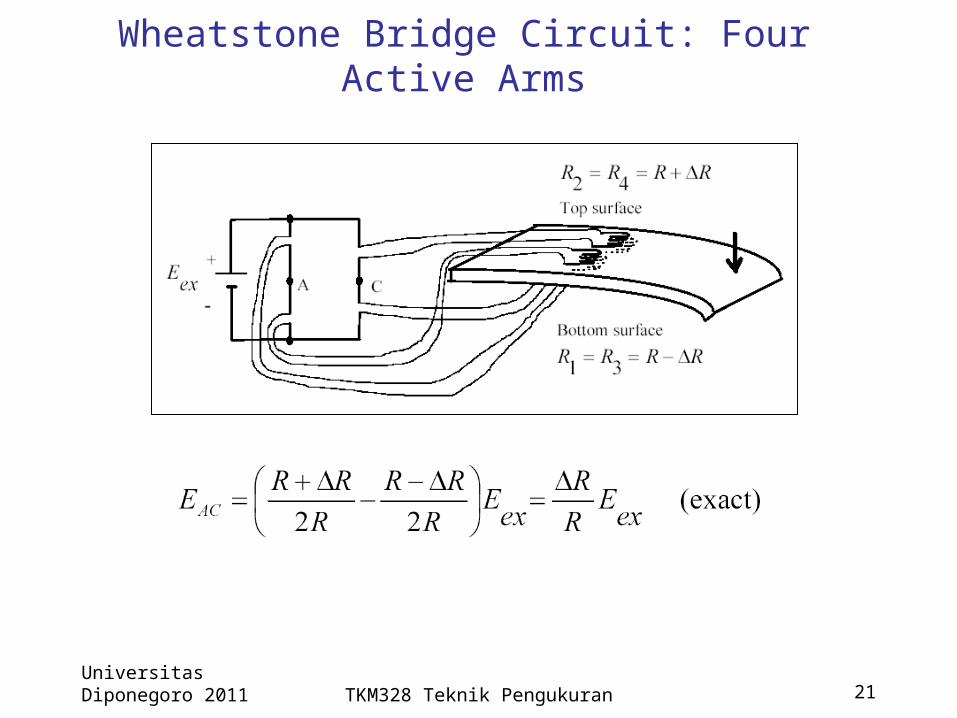
Wheatstone Bridge Circuit: Four Active Arms

Universitas Diponegoro 2011 TKM328 Teknik Pengukuran 22
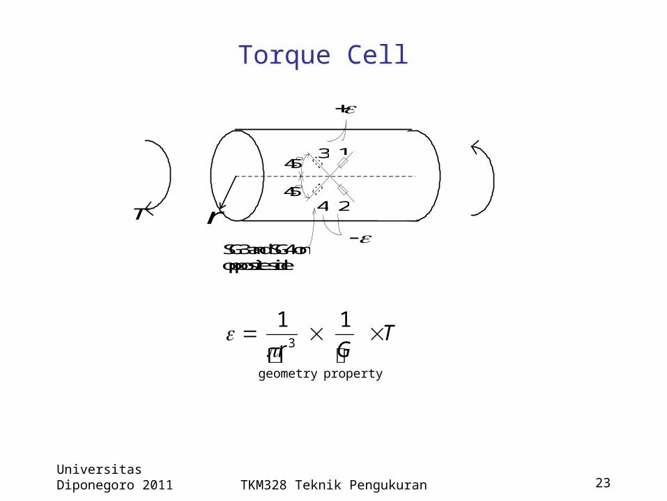
Torque CellA (static) torque may be measured by observing the angular deflection of
a bar or hollow cylinder.The torque is related to the deflection angle by
where, T : applied torque (Nm)G : Shear Modulus of elasticity(N/m2)
E = Young’s Modulus(N/m2) = Poisson’s ratioro = Outside radius (m) L = Length of cylinder (m)ri = Inside radius (m) φ = angular deflection (rad)
L
rrGT io
2
44
T
ro
ri
L
No torque applied
Torque T applied
12EG
Universitas Diponegoro 2011 TKM328 Teknik Pengukuran 23
Torque Cell
T
r
1
2
3
4
SG3 and SG4 onopposite side
45
45
T
Gr
propertygeometry
3
11