08-14 wrx/08+sti air oil separator for top mounted
TRANSCRIPT

08-14 WRX/08+STI Air Oil Separator for Top Mounted Intercooler Setups
2021-03-01 PSP-ENG-606 Thank you for purchasing this PERRIN product for your car! Installation of this product should only be performed by persons experienced with installation of aftermarket performance
parts and proper operation of high performance vehicles. If vehicle needs to be raised off the ground for installation, the installer must use proper jacks, jack-stands and/or a professional vehicle hoist for safety of the installer and to protect property. If the vehicle is lifted improperly, serious injury or death may occur! Please read through all instructions before performing any portion of installation. Always use appropriate personal proection equipment such as gloves, eye and hearing protection for installation of this product. If you
have any questions, please contact our tech department prior to starting installation. We can be reached in any of the following methods:
Email [email protected] Instant Chat off the main page of www.PERRINperformance.com
Or simply call our tech team at 503-693-1702
WARNING: This product can expose you to chemicals including Lead which is known to the State of California to cause cancer birth defects or other reproductive harm. For more information, go to www.P65Warnings.ca.gov
GENERAL MODIFICATION NOTE Modifications to any vehicle can change the handling and performance. As with any vehicle extreme care must be used to prevent loss of control or roll-over during sharp turns or
abrupt maneuvers. Always wear seat belts, and drive safely, recognizing that reduced speeds and specialized driving techniques may be required. Failure to drive a vehicle safely may result in serious injury or death. Do not drive a vehicle unless you are familiar with its unique handling characteristics and are confident of your ability to maintain control under all driving conditions. Some modifications (and combinations of modifications) are not recommended and may not be permitted in your state or country. Consult the owner’s manual, service manual, instructions accompanying these products, and local laws before purchasing and installing these modifications. You are responsible for the legality and safety of the
vehicle you modify using these components.
SPECIAL NOTES: • Installation of this part should be performed by a qualified technician as this is a complicated and time-consuming installation with many different steps and optional hook
ups along the way.
• Read through entire installation before starting this project. There is a decent amount of planning needed for hose routing, and it is important to understand the full installation before beginning installation of the AOS.
• The included foam filter/diffuser is not recommended to be used in climates that drop below freezing temps. Normal water vapor that travels through the engine can collect on this and freeze, causing a restriction in flow through the AOS. The AOS will function perfectly fine with this piece removed. This diffuser is recommended for race cars that can see excessive oil sloshing into the heads during high “G” cornering, as this helps diffuse any massive amounts of oil that could reach the AOS.
• We have provided a couple of methods on how to hook this up to your engine. Keep in mind there are many variations of how this can be installed. Consult your tuner or qualified technician before installing this part on your car to better determine how it should be setup on your vehicle.
• The PERRIN Air Oil Separator (AOS) was designed to remove a significant amount of the oil and water vapor that normally gets sent to your intake system to be ingested by your engine. There are many variables as to how much oil will make it past our AOS, but expect it to remove a significant amount of the crank case blow by. For cars with built engines with excessive blow-by, you may still experience oil getting past our Air Oil Separator.
NPT Notes: • There are many NPT (National Pipe Thread) fittings included with your Air Oil Separator. Throughout the instructions, these notes below will be referred to, and it’s
important to understand these types of fittings and how they work.
• NPT fittings are a tapered thread that seals when tightened, not bottomed out. Thread fittings in by hand and tighten roughly 1/2 to 1 full turn more until fitting is tight. NOTE: Using a small amount of Teflon tape on threads is a good idea to ensure a proper seal. Teflon tape is rated to work up to 500F and is impervious to all chemicals that your AOS will see. This is highly recommended to use over any other sealant.
• Angle of 90 degree fittings can be adjusted after tightening, as long as they are not backed off more than 1/4 of a turn.
Included Parts with PERRIN Air Oil Separator for Top Mount Intercoolers: • (1) PERRIN Universal Air Oil Separator (AOS)
• (1) O-rings
• (1) 08-13 TMIC AOS Bracket
• (1) Crank Case Vent Adapter
• (9’) 1/2” Crank Case Vent Hose
• (1.625”) 3/4” Crank Case Vent Hose
• (3’) 3/8” Fuel Injection Hose
• (5’) 5/16” Coolant Hose
• (4’) 5/16” Fuel Injection Hose
• (9) #3 Hose Clamps
• (4) #2 Hose Clamps
• (2) #27mm Hose Clamp
• (1) 1/2” Vacuum Cap
• (2) 3/8 NPT 1/2” Straight Fitting
• (2) 3/8 NPT 1/2" 90 Degree Fitting
• (1) 1/4 NPT 3/8” Barb Straight Fitting
• (1) 3/8 NPT- 1/2” Barb Female Fitting

• (2) 1/4 NPT 1/2” Barb Straight Fitting
• (2) 1/8 NPT 5/16” 90 Degree Barb Fitting
• (1) 1/8NPT 5/16” 90 Degree Barb Fitting
• (2) 1/8 NPT 5/16” Straight Barb Fitting
• (2) 1/2" Y Connector
• (1) 1/2” Tee Connector
• (2) 1/2”-1/2” Connector
• (1) 5/16”-5/16” Connector
• (1) 5/8-1/2” Connector
• (3) 3/8 NPT Plug
• (2) 1/4 NPT Plug
• (1) M10x80mm Hex Bolt
• (1) M10 Nut
• (8) 3/8” Washers
• (3) M8x16mm Button Head Cap Screw
• (3) M8 SS Washers
• (2) M6x14mm Button Head Cap Screw
• (2) M6 SS Washer
• (1) M4 Hex Wrench
• (1) M5 Hex Wrench
• (1) M6 Hex Wrench
• (20) Zip Ties
Installation Instructions 1. Using the above diagram as a guide, take note of all fittings and our recommended connections. There are many options and many ways to install this.
Please read through all instructions before proceeding with install. 2. Locate and remove intercooler (including Y-pipe and throttle body coupler) from engine or any boost tubes connected to turbo and throttle body. This is
necessary to gain access to center crank case vent, PCV system and other items.
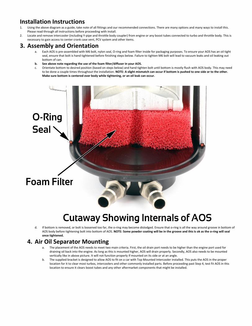
3. Assembly and Orientation a. Each AOS is pre-assembled with M6 bolt, nylon seal, O-ring and foam filter inside for packaging purposes. To ensure your AOS has an oil tight
seal, ensure that bolt is hand tightened before finishing steps below. Failure to tighten M6 bolt will lead to vacuum leaks and oil leaking out bottom of can.
b. See above note regarding the use of the foam filter/diffuser in your AOS. c. Orientate bottom to desired position (based on steps below) and hand tighten bolt until bottom is mostly flush with AOS body. This may need
to be done a couple times throughout the installation. NOTE: A slight mismatch can occur if bottom is pushed to one side or to the other. Make sure bottom is centered over body while tightening, or an oil leak can occur.
d. If bottom is removed, or bolt is loosened too far, the o-ring may become dislodged. Ensure that o-ring is all the way around groove in bottom of
AOS body before tightening bolt into bottom of AOS. NOTE: Some powder coating will be in the groove and this is ok as the o-ring will seal once tightened.
4. Air Oil Separator Mounting a. The placement of the AOS needs to meet two main criteria. First, the oil drain port needs to be higher than the engine port used for
draining oil back into the engine. As long as this is mounted higher, AOS will drain properly. Secondly, AOS also needs to be mounted vertically like in above picture. It will not function properly if mounted on its side or at an angle.
b. The supplied bracket is designed to allow AOS to fit on a car with Top Mounted Intercooler installed. This puts the AOS in the proper location for it to clear most turbos, intercoolers and other commonly installed parts. Before proceeding past Step 4, test fit AOS in this location to ensure it clears boost tubes and any other aftermarket components that might be installed.

c. Locate main engine wire harness and bracket holding it to chassis. Remove wire harness from bracket by lifting tab under plug and sliding off toward engine. Rear portion of wire harness is secured to bracket with a plastic loop fastener. Pinch small tabs (holding harness and fastener to bracket) and pull harness toward firewall. Note: 2015+ STI models will not have any clips to deal with as described above.
d. Locate then remove (2) M6 bolts holding bracket to shock tower. Note: 2015+ STI models only have one bolt securing bracket to chassis, and will not reuse bracket.
e. Bend rear tab of OEM bracket down toward chassis as shown below. Note: 2015+ STI models can skip this step. f. Using diagrams below for reference, install bracket to AOS body using supplied M8 bolts and SS washers. Slide bracket up as far as it can
go in the slots and tighten bolts. Note: This can be readjusted in a later step.
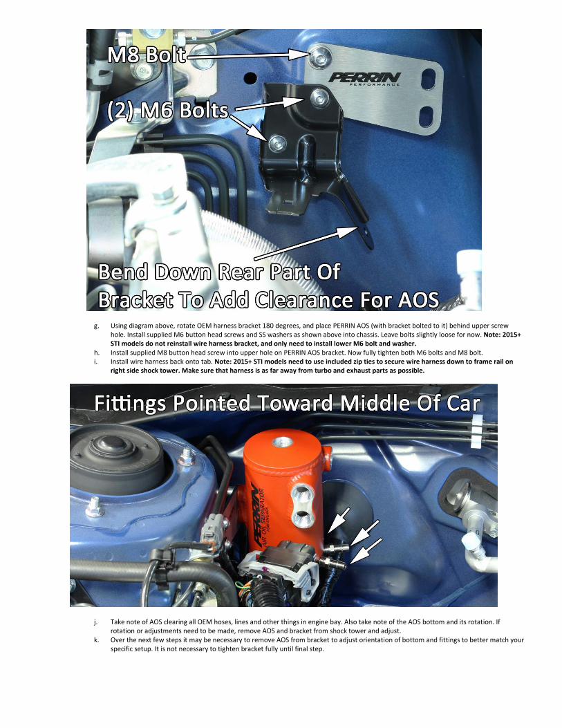
g. Using diagram above, rotate OEM harness bracket 180 degrees, and place PERRIN AOS (with bracket bolted to it) behind upper screw hole. Install supplied M6 button head screws and SS washers as shown above into chassis. Leave bolts slightly loose for now. Note: 2015+ STI models do not reinstall wire harness bracket, and only need to install lower M6 bolt and washer.
h. Install supplied M8 button head screw into upper hole on PERRIN AOS bracket. Now fully tighten both M6 bolts and M8 bolt. i. Install wire harness back onto tab. Note: 2015+ STI models need to use included zip ties to secure wire harness down to frame rail on
right side shock tower. Make sure that harness is as far away from turbo and exhaust parts as possible.
j. Take note of AOS clearing all OEM hoses, lines and other things in engine bay. Also take note of the AOS bottom and its rotation. If rotation or adjustments need to be made, remove AOS and bracket from shock tower and adjust.
k. Over the next few steps it may be necessary to remove AOS from bracket to adjust orientation of bottom and fittings to better match your specific setup. It is not necessary to tighten bracket fully until final step.
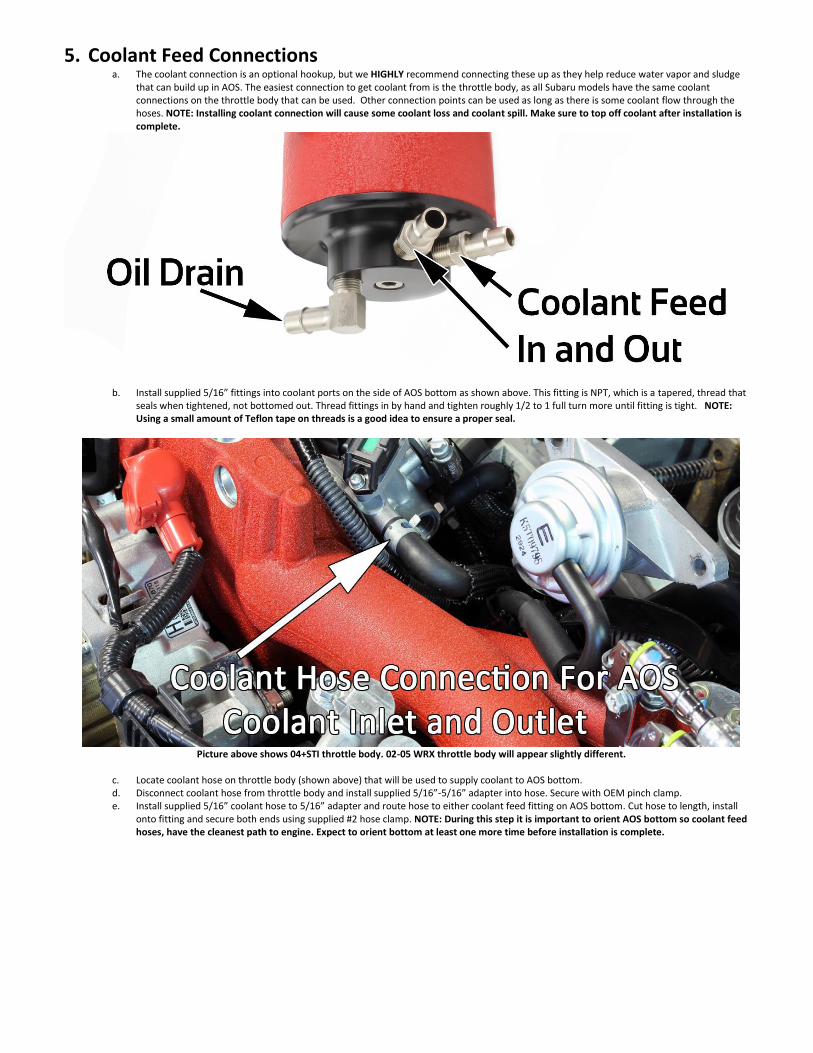
5. Coolant Feed Connections a. The coolant connection is an optional hookup, but we HIGHLY recommend connecting these up as they help reduce water vapor and sludge
that can build up in AOS. The easiest connection to get coolant from is the throttle body, as all Subaru models have the same coolant connections on the throttle body that can be used. Other connection points can be used as long as there is some coolant flow through the hoses. NOTE: Installing coolant connection will cause some coolant loss and coolant spill. Make sure to top off coolant after installation is complete.
b. Install supplied 5/16” fittings into coolant ports on the side of AOS bottom as shown above. This fitting is NPT, which is a tapered, thread that
seals when tightened, not bottomed out. Thread fittings in by hand and tighten roughly 1/2 to 1 full turn more until fitting is tight. NOTE: Using a small amount of Teflon tape on threads is a good idea to ensure a proper seal.
Picture above shows 04+STI throttle body. 02-05 WRX throttle body will appear slightly different.
c. Locate coolant hose on throttle body (shown above) that will be used to supply coolant to AOS bottom. d. Disconnect coolant hose from throttle body and install supplied 5/16”-5/16” adapter into hose. Secure with OEM pinch clamp. e. Install supplied 5/16” coolant hose to 5/16” adapter and route hose to either coolant feed fitting on AOS bottom. Cut hose to length, install
onto fitting and secure both ends using supplied #2 hose clamp. NOTE: During this step it is important to orient AOS bottom so coolant feed hoses, have the cleanest path to engine. Expect to orient bottom at least one more time before installation is complete.

Actual routing of hoses may not be represented above. Diagram shows simplified path to help visualize routing.
2008+ WRX coolant hose routing shown above. Diagram shows simplified path to help visualize routing.
f. Install remaining 5/16” coolant hose to 5/16” fitting on AOS bottom and secure with supplied #2 clamp. Route hose back to fitting left open on
throttle body and secure with supplied #2 hose clamp. NOTE: Orient AOS bottom again, to ensure the cleanest path to engine. Expect to orient bottom at least one more time before installation is complete.
g. Using above diagram, you can visualize the coolant hose connections for all cars. This diagram has been simplified to show the hose routing. Hoses can be routed differently depending on where the AOS is mounted or if intercooler plumbing requires this. Keep in mind that the coolant fittings on the AOS become part of the coolant path from engine to throttle body.

6. Oil Drain and Crank Case Vent Connection The AOS oil drain is NOT an optional hook-up as the AOS is not designed to contain oil within itself. This fitting is used to drain the oil that is captured within the AOS body back to the engine through a crank case vent.
a. There are three different sets of instructions below depending on which vehicle you have (08+STI, 08-10 WRX, and 11-14 WRX).
b. Install supplied 5/16” 90 degree fitting into oil drain outlet (shown in diagram above) in bottom of AOS keeping in mind that this needs to point
in the direction the drain hose will be routed. See NPT Notes above regarding installation of this fitting. c. Using diagrams below, locate OEM PCV/crank case vent junction and remove from engine, turbo inlet hose, and intake manifold. This step will
vary depending on car this is being installed on. The same basic steps need to be taken, with removal of junction from car, then capping connection at turbo inlet hose.
i. When removing PCV Junction from the 08+ STI, there is a PCV diagnosis connector (electrical connection) where hose meets the turbo inlet hose. Remove hose from PCV diagnosis connector, leaving nipple open and electrical connection connected to turbo inlet hose, as well as crank case vent on block fitting open. See diagram below which shows throttle body removed to make picture clearer. Continue to step “e”.
Picture above shows typical 2008+ STI PCV Junction and Inlet Hose
Above picture shows 2008 STI with PCV junction exposed.

ii. When removing PCV Junction on 2008-10 WRX models, there is a PCV diagnosis connector where the PCV junction meets a hose going to turbo inlet hose (See diagram below). Disconnect PCV diagnosis connector from PCV junction, disconnect electrical plug from PCV junction and remove junction with hoses going to intake manifold and turbo inlet hose. This will leave nipple on turbo inlet hose open as well as crank case vent on block.
Above diagram shows 2008-10 WRX PCV junction.
iii. Using pictures below locate pin inside of PCV diagnosis connector and remove using needle nose pliers. Install pin into female pins
on PCV diagnosis harness. Use electrical tape to secure fitting and protect against it grounding out on components. This step will bypass this sensor so there is no check engine light. Continue to step “e”.
Above diagrams show pin being removed from PCV diagnosis connector and the connector with female pins to reinstall it to.
iv. When removing PCV Junction on 2011-14 WRX models, there is a PCV diagnosis connector where the PCV junction meets a hose
going to turbo inlet hose (See diagrams below). Remove PVC diagnosis connector from the PCV junction (leaving electrical connection alone). Remove junction with hose going to intake manifold. This will leave nipple on PCV diagnosis connector as well as crank case vent on block. Alternatively, you can remove PCV diagnosis connector and follow instructions for 2008-10 WRX models. This makes for a cleaner installation but also requires bypassing the PCV diagnosis connector.
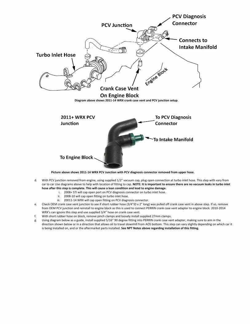
Diagram above shows 2011-14 WRX crank case vent and PCV junction setup.
Picture above shows 2011-14 WRX PCV Junction with PCV diagnosis connector removed from upper hose.
d. With PCV junction removed from engine, using supplied 1/2” vacuum cap, plug open connection at turbo inlet hose. This step with vary from
car to car Use diagrams above to help with location of fitting to cap. NOTE: It is important to ensure there are no vacuum leaks in turbo inlet hose after this step is complete. This will cause a lean condition and lead to engine damage.
i. 2008+ STI will cap open port on PCV diagnosis connector on turbo inlet hose. ii. 2008-10 will cap open fitting on turbo inlet hose.
iii. 20011-14 WRX will cap open fitting on PCV diagnosis connector. e. Check OEM crank case vent junction to see if short rubber hose (3/4”ID x 2” long) was pulled off crank case vent in above step. If so, remove
from OEM PCV junction and reinstall to engine block as this is used to connect PERRIN crank case vent adapter to engine block. 2010-2014 WRX’s can ignore this step and use supplied 3/4” hose on crank case vent.
f. With short rubber hose on block, remove pinch clamps and loosely install supplied 27mm clamps. g. Using diagram below as a guide, install supplied 5/16” 90 degree fitting into PERRIN crank case vent adapter, making sure to aim in the
direction shown below or in a direction that allows oil to travel downhill from AOS bottom. This step can vary slightly depending on which car it is being installed on, and or the aftermarket parts installed. See NPT Notes above regarding installation of this fitting.

Direction of fitting shown that works for most installations. Fitting can be rotated in any other direction as long as oil draining from the AOS can maintain a
downhill path to fitting.
h. Using diagram above, install supplied 1/2" straight fitting into PERRIN crank case vent adapter. See NPT Notes above regarding installation of this fitting.
i. Install PERRIN crank case adapter into supplied 3/4" hose on engine crank case vent and secure using supplied 27mm hose clamp.
Diagram shows a typical 2008+ STI with simplified path to help visualize routing.

Diagram shows a typical 2008-14 WRX with simplified path to help visualize routing.
a. Using diagrams above and supplied 5/16” fuel injection hose, connect oil drain outlet on bottom of AOS to 5/16” 90 degree fitting on PERRIN
crank case vent junction. Secure both ends using supplied #2 hose clamps. NOTE: It is very important to route this hose such that it NEVER travels uphill from bottom of AOS to crank case vent fitting. Also during this step it is important to orient bottom so drain and the next step of installing coolant feed, has the cleanest path to engine.
b. Using diagrams above and supplied 1/2" Emissions Hose, connect 1/2" fitting on PERRIN crank case vent junction to 1/2" fitting on side of AOS. The direction of this fitting is not critical and can be adjusted to fit your installation. Use supplied #3 clamps to secure both ends. NOTE: Routing of this vent hose is not that important, just makes sure it is not pinched off while traveling to AOS body.
c. For cars that see an extreme amount of high G’s or an excessive amount of blow by, we recommend a slightly different installation for the crank case vent hoses. See special notes below for this.
7. Valve Cover Vent Inlet Connections Your Subaru engine has a valve cover vent on both left and right heads that need to be routed to the AOS. The method for doing this can vary depending on the desired setup. Read through all 3 options below before deciding which is best for your setup.
a. Most all models will appear to have two vents on each valve cover and two crank case vents, only one set of these are considered vents, the other set we consider balance vents. These balance vents connect both valve covers to center crank case vent together with piping and hoses, and are to be left alone. Using diagram below, locate valve cover vents that toward the front of the engine, and connect to piping on intercooler.
b. Once proper set of valve cover vents are located, decide if you want to:
i. Use OEM piping on top mounted intercooler as the “T” connection, and use only one of the two AOS valve cover inlet ports. This is the simplest and cleanest method (Shown below in picture of AOS in engine bay). Continue to Step “c” below.
ii. Join both valve cover vents using supplied “T” or ”Y” connector, replacing all OEM hoses with supplied 1/2” emissions hose and using only one valve cover vent inlet port on AOS. This method is preferred if OEM hoses are old and hard, or aftermarket parts may be installed affecting installation. (Shown below in picture of AOS on engine stand). Continue to Step “d” below.

iii. Connect each valve cover vent separately to each of the AOS valve cover vent inlet ports. This method is what we recommend to provide the best venting while under high lateral G forces. If connecting each vent separately, skip to step “g”.
c. If you are using the OEM piping as your “T” connection, install (1) supplied 1/2” barbed 3/8NPT straight fitting into one of the AOS valve cover vent inlets. Install supplied 3/8NPT plug into remaining valve cover vent inlet. See NPT Notes above regarding installation of these fittings.
i. For STI models, remove OEM rubber hose from piping on intercooler connecting to turbo inlet hose. Using supplied 1/2" emissions hose connect pipe on intercooler to 1/2" fitting installed on AOS valve cover vent inlet port. See diagram below showing piping or “T” Junction on intercooler and hose connecting it to the AOS. Continue to Step 8.
The above setup shows a simple setup that uses the OEM valve cover vent piping (bolted to the intercooler). The extra port on AOS that gets plugged, is not
seen in the picture above as the hose is covering it up.
ii. For WRX models, locate OEM rubber hose connecting plastic valve cover vent piping to turbo inlet hose. Remove bolts securing plastic piping to intake manifold and pull away from engine to remove rubber hose from inlet hose. Install supplied 5/8”-1/2" connector into rubber hose. Install supplied 1/2” emissions hose to fitting and route hose under manifold to AOS valve cover vent inlet port. See diagram below showing piping or “T” Junction on intake manifold. Reinstall plastic valve cover piping to intake manifold. Continue to Step 8.

d. If you are connecting each valve cover vent to the AOS using supplied hose and “Tee” or “Y” fitting, install (1) supplied 1/2” barbed 3/8NPT
straight fitting into one of the AOS valve cover vent inlets. Install supplied 3/8NPT plug into remaining valve cover vent inlet. See NPT Notes above regarding installation of this fitting.
e. Remove all OEM valve cover vent hoses and piping up to turbo inlet hose. This step varies from WRX to STI and model year to model year. i. For 2008+ STI and 2008-10 WRX models, install supplied 1/2" emissions hose onto each valve cover vent, join left and right side
with supplied “Y” or “T” connector, and secure with supplied clamps. See diagram below showing “Y” connector being used. NOTE: We recommend removing all OEM rubber valve cover vent hoses as they become very brittle over time.
ii. For 2017+ STI models, take note of additional PCV diagnosis connectors on each hose coming off valve cover vents. See diagram below showing this. Remove hose between PCV diagnosis connectors and intercooler piping (leaving them electrically connected) and install supplied 1/2" emissions hose onto each fitting. Join left and right side with supplied “Y” or “T” connector, and secure with supplied clamps. If done correct, hoses from valve covers to PCV diagnosis connector will be left alone. See additional diagram below showing “Y” connector being used
Actual routing of hoses may not be represented above. Diagram shows simplified path to help visualize routing.

iii. For 2008-11 WRX models, locate and remove plastic valve cover vent piping from engine. See diagram above and below showing plastic piping and its location. Install supplied 1/2" emissions hose onto each valve cover vent port. Join left and right side with supplied “Y” or “T” connector, and secure with supplied clamps.
Actual routing of hoses may not be represented above. Diagram shows 08-14 WRX with simplified path to help visualize routing whether using OEM
hoses or supplied.

iv. For 2012-14 WRX models, take note of additional PCV diagnosis connectors on each hose coming off valve cover vents. See
diagram above showing this. Remove hose between PCV diagnosis connectors and piping (leaving them electrically connected) and install supplied 1/2" emissions hose onto each fitting. Join left and right side with supplied “Y” or “T” connector, and secure with supplied clamps. If done correct, hoses from valve covers to PCV diagnosis connector will be left alone. See additional diagram above showing “Y” connector being used.
f. Connect third leg of “Y” or “T” to 1/2" fitting used on AOS valve cover vent inlet port. You can see in the diagrams typical routing found on the most common setups. Continue onto Step 8. NOTE: Make sure that the routing of hoses does not interfere with moving parts or travel over extremely hot parts like a turbo or downpipe.
g. If you are connecting each valve cover vent separately to the AOS, install supplied 1/2” barbed 3/8NPT straight fittings into each of the valve cover vent inlet ports. See NPT Notes above regarding installation of this fitting.
h. Follow above instructions, but instead of using a “T” or “Y” to join each valve cover together, run 1/2” emissions hose to each of the 1/2" fittings installed into the AOS valve cover vent inlet ports. Secure with supplied #3 hose clamps. NOTE: Make sure that the routing of hoses does not interfere with moving parts or travel over extremely hot parts like turbo or downpipe.
8. Outlet and PCV Connection The AOS outlet is the top threaded hole on body. This connection needs to be connected to the turbo intake system in front of the turbocharger, and behind the air filter. NOTE: We do not recommend leaving this fitting open as oil and oil vapor can still come out under certain conditions, which can create a mess or combust if exposed to extreme heat. There are two options to connect the AOS to your intake system. One is installing it with the PCV system functioning, and the other is removing the PCV system. The PCV is a 1-way valve that provides crank case ventilation during idle and light load situations, but it can also be a partial source of oil vapors getting into sucked into the intake manifold. For most street driven vehicles, installing the PCV valve is a good idea, but for built motors and track cars, we recommend removing this. Read through all instructions below, then read PCV Delete Instructions, before deciding how to proceed.
a. Along this hose (connecting AOS top to intake system) we recommend installing the “Y” connection used for the PCV (positive crankcase vent). The PCV is a 1-way valve that provides crank case ventilation during idle and light load situations. This valve is important to install as described or boost pressure will be lost and there will be no positive crankcase ventilation occurring. NOTE: The PCV connection can be skipped for certain applications, see special note below regarding this.
b. Locate PCV junction removed from engine block in earlier step and remove PCV valve from junction as shown below.

Rubber junction from 2011+ WRX model shown above.
i. For models with plastic junction, this can be tight to remove and may require a vise to hold housing while fitting is unscrewed.
It may be necessary to use solvent or a thread penetrating oil to free from housing. ii. Once PCV is removed, install into supplied fitting and tighten down. See NPT Notes above regarding installation of this fitting.
iii. Models (WRX only) that have the rubber type junction, simply remove PCV valve and install into hoses as shown in later steps. c. Install supplied 1/2” barb 3/8NPT 90 degree connector into top of AOS. See NPT Notes above regarding installation of this fitting. d. Locate previous PCV vacuum connection on intake manifold and connect supplied 3/8” hose to fitting and secure with clamp.
i. For STI models, this port is located under the throttle body as shown below. ii. For WRX models, this port is located on a steel plate bolted to the middle of the back of the intake manifold as shown below.

Above picture shows PCV port connection on STI model.
Above picture shows PCV port on 2008-14 WRX manifold.
e. Using supplied 1/2” emissions hose, connect AOS outlet (top fitting) to intake vacuum source at turbo inlet hose.
i. For 2002-07 WRX and 2004-11 STI models, cut OEM rubber vacuum hose after bends. Use supplied 1/2"-1/2” connector to join OEM rubber hose to 1/2" emissions hose. See diagram below.

ii. For 2012+ STI models, remove OEM rubber vacuum hose at white PCV diagnosis connector and connect 1/2” emissions hose to
fitting. Make sure to leave electrical connection connected or a check engine light will occur. See example diagram below.
iii. For 2008-14 WRX models, locate fitting on turbo inlet hose (as shown below) located under intake manifold. Make sure that short rubber hose is left on turbo inlet hose. Install supplied 1/2"-1/2” fitting into short rubber hose and secure with supplied clamps.
iv. Vehicles with aftermarket turbo inlet hose will use one of the above installation methods depending on what is supplied with the inlet hose. If installing with PERRIN inlet hose, no additional fittings are needed.

Above picture shows intake vacuum source at turbo inlet hose on 2012+ STI engine with extra PCV diagnosis connector.
f. Decide where to install PCV valve (one- way valve) and “Y” connector along 1/2" emissions hose coming from AOS outlet. NOTE: The location of
this is not important as long as it’s along the hose between the AOS top and the turbo intake system. Below are a couple diagrams with different options as to where to make this junction.
Picture shows Y junction installed at AOS, and PCV location. PCV location does not need to be this close to AOS.
g. Once desired location is found, cut 1/2" emissions hose and install supplied “Y” connector making sure to aim 3rd leg back toward AOS away
from Turbo Intake Vacuum source. Use above and below diagrams to give you a better idea how this can be setup. It is not critical as to the location of PCV valve itself. It can be located close to intake manifold or right at AOS outlet and it will not affect how system works.

Above diagram shows an example of an STI model.
h. For both WRX and STI models, cut a piece of 1/2" emissions hose (2” is what is shown in pictures) and install over 3rd leg of “Y” connector as
shown in above and below diagrams. Install 1/2" side of PCV valve assembly (assembled earlier in step 8) into 1/2" emissions hose. Install supplied clamp and tighten down on hose.
i. Route previously installed 3/8” fuel hose from intake manifold PCV fitting to 3/8” fitting on PCV valve. Cut hose to length and secure hose with supplied clamps. Using above diagram, ensure that PCV valve (one-way valve) is installed in the correct direction and on the correct leg of “Y” connector.
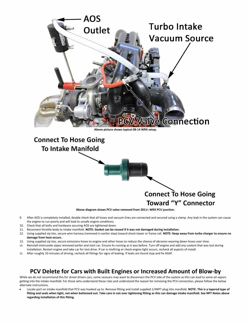
Above picture shows typical 08-14 WRX setup.
Above diagram shows PCV valve removed from 2011+ WRX PCV junction.
9. After AOS is completely installed, double check that all hoses and vacuum lines are connected and secured using a clamp. Any leak in the system can cause
the engine to run poorly and will lead to unsafe engine conditions. 10. Check that all bolts and hardware securing AOS are tightened down. 11. Reconnect throttle body to intake manifold. NOTE: Gasket can be reused if it was not damaged during installation. 12. Using supplied zip ties, secure wire harness (removed in earlier step) toward shock tower or frame rail. NOTE: Keep away from turbo charger to ensure no
damage from heat occurs. 13. Using supplied zip ties, secure emissions hoses to engine and other hoses to reduce the chance of abrasion wearing down hoses over time. 14. Reinstall intercooler pipes removed earlier and start car. Ensure its running as it was before. Turn off engine and add any coolant that was lost during
installation. Restart engine and take car for test drive. If car is misfiring or check engine light occurs, recheck all aspects of install. 15. After roughly 10 minutes of driving, recheck all fittings for signs of leaking. If leaks are found stop and fix ASAP.
PCV Delete for Cars with Built Engines or Increased Amount of Blow-by While we do not recommend this for street driven cars, some racecars may want to disconnect the PCV side of the system as this can lead to some oil vapors getting into the intake manifold. For those who understand these risks and understand the reason for removing the PCV connection, please follow the below alternate instructions. • Locate port on intake manifold that PCV was hooked up to. Remove fitting and install supplied 1/4NPT plug into manifold. NOTE: This is a tapered type of
fitting and seals when tight, not when bottomed out. Take care in not over tightening fitting as this can damage intake manifold. See NPT Notes above regarding installation of this fitting.
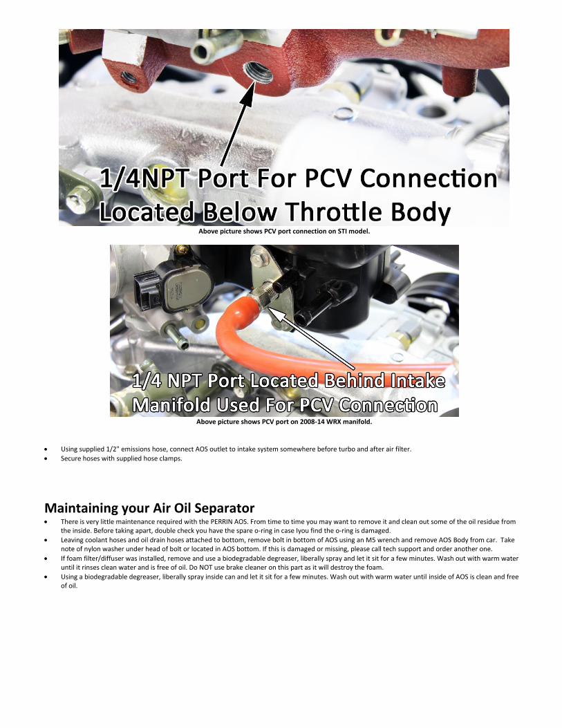
Above picture shows PCV port connection on STI model.
Above picture shows PCV port on 2008-14 WRX manifold.
• Using supplied 1/2" emissions hose, connect AOS outlet to intake system somewhere before turbo and after air filter.
• Secure hoses with supplied hose clamps.
Maintaining your Air Oil Separator • There is very little maintenance required with the PERRIN AOS. From time to time you may want to remove it and clean out some of the oil residue from
the inside. Before taking apart, double check you have the spare o-ring in case Iyou find the o-ring is damaged.
• Leaving coolant hoses and oil drain hoses attached to bottom, remove bolt in bottom of AOS using an M5 wrench and remove AOS Body from car. Take note of nylon washer under head of bolt or located in AOS bottom. If this is damaged or missing, please call tech support and order another one.
• If foam filter/diffuser was installed, remove and use a biodegradable degreaser, liberally spray and let it sit for a few minutes. Wash out with warm water until it rinses clean water and is free of oil. Do NOT use brake cleaner on this part as it will destroy the foam.
• Using a biodegradable degreaser, liberally spray inside can and let it sit for a few minutes. Wash out with warm water until inside of AOS is clean and free of oil.
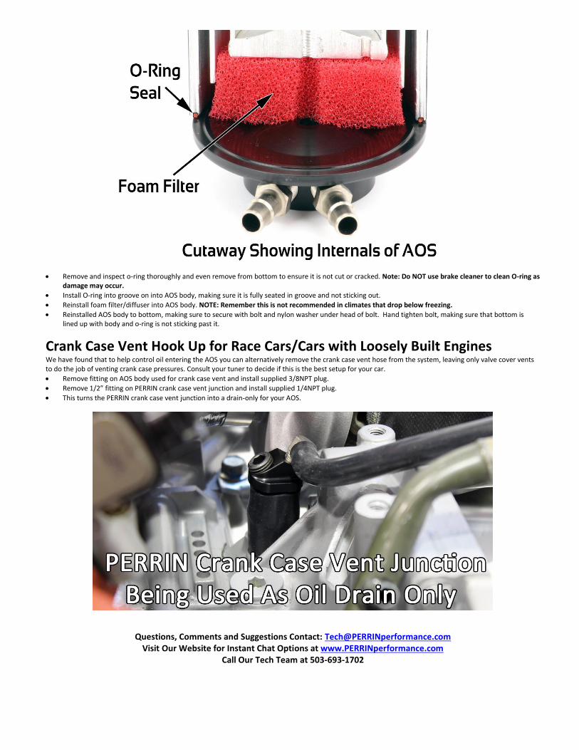
• Remove and inspect o-ring thoroughly and even remove from bottom to ensure it is not cut or cracked. Note: Do NOT use brake cleaner to clean O-ring as damage may occur.
• Install O-ring into groove on into AOS body, making sure it is fully seated in groove and not sticking out.
• Reinstall foam filter/diffuser into AOS body. NOTE: Remember this is not recommended in climates that drop below freezing.
• Reinstalled AOS body to bottom, making sure to secure with bolt and nylon washer under head of bolt. Hand tighten bolt, making sure that bottom is lined up with body and o-ring is not sticking past it.
Crank Case Vent Hook Up for Race Cars/Cars with Loosely Built Engines We have found that to help control oil entering the AOS you can alternatively remove the crank case vent hose from the system, leaving only valve cover vents to do the job of venting crank case pressures. Consult your tuner to decide if this is the best setup for your car.
• Remove fitting on AOS body used for crank case vent and install supplied 3/8NPT plug.
• Remove 1/2” fitting on PERRIN crank case vent junction and install supplied 1/4NPT plug.
• This turns the PERRIN crank case vent junction into a drain-only for your AOS.
Questions, Comments and Suggestions Contact: [email protected] Visit Our Website for Instant Chat Options at www.PERRINperformance.com
Call Our Tech Team at 503-693-1702