06 ra41236en06gla1 mobility operation and signaling
DESCRIPTION
06 RA41236EN06GLA1 Mobility Operation and SignalingTRANSCRIPT

RA41236EN06GLA1
Mobility Operation and Signaling
1

RA41236EN06GLA1
Mobility Operation and Signaling
2
RA41236EN06GLA1
Mobility Operation and Signaling
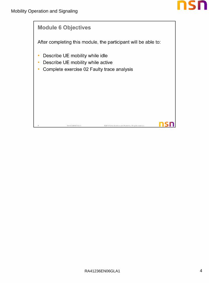
4

RA41236EN06GLA1
Mobility Operation and Signaling
5

RA41236EN06GLA1
Mobility Operation and Signaling
6
When registered to the EPS network, UE may move from one cell to another, from one registration area to another or even leave the EPS network and return back in other time. When moving, UE is possibly in active connection (ECM_CONNECTED) or idle conditions (ECM_IDLE).
The EPS mobility management (EMM) comprises functions and procedures that maintain the connectivity between UE and EPS as UE moves between the coverage areas of different base stations or access networks.

RA41236EN06GLA1
Mobility Operation and Signaling
7
To support EMM, set of mobility management functions and procedures have been implemented on LTE/EPC network elements.
Mobility management in the E-UTRAN comprises:
• Cell selection. UE performs cell selection e.g. as part of PLMN selection and when moves to RRC_IDLE.
• Cell reselection. UE performs cell reselection in ECM_IDLE in order to ensure that it is camped on to the best cell in providing normal services.
• Handover. It is the main mobility management procedures when UE is in ECM_CONNECTED.
• Path Switching. This is the procedure to switch downlink user data path during inter-eNB handover without SGW relocation.
• Data Forwarding. This is the procedure to forward user data from source eNB to target eNB during inter-eNB handover.
• Mobility management in the EPC comprises:
• Reachability management for the UE in ECM_IDLE. The function within EPC to ensure that the UE is always reachable by paging for new data arrival.
• Tracking Area (TA) list management. Tracking Area list management comprises the functions to allocate and reallocate a Tracking Area Identity list to the UE.
• Mobility anchor point. The functional entity that anchors the user plane for E-UTRAN mobility and mobility toward others 3GPP Radio Access Technology .
• Idle mode signaling reduction. This function provides a mechanism to limit signaling during inter-RAT cell-reselection in idle mode.
• Mobility restriction. It comprises functions for restrictions to mobility handling of a UE in E-UTRAN access.

RA41236EN06GLA1
Mobility Operation and Signaling
8
The UE mobility in ECM_IDLE is handled by:
• Cell selection/reselection.
• Attach/detach.
• Tracking Area Update procedure.

RA41236EN06GLA1
Mobility Operation and Signaling
9
Mobility Management in ECM_CONNECTED state is handled by handover procedure.

RA41236EN06GLA1
Mobility Operation and Signaling
10
In RRC_CONNECTED state , the network controls UE mobility, i.e. the network decides when the UE shall move to which cell (which may be on another frequency or RAT). The network triggers the handover procedure e.g. based on for example radio conditions or load. To facilitate this, the network may configure the UE to perform measurement reporting (possibly including the configuration of measurement gaps). The network may also initiate handover blindly, i.e. without having received measurement information from the UE. Blind handovers are usually used when both source and target cells occupy the same physical area so mobility can be more-or-less guaranteed.

RA41236EN06GLA1
Mobility Operation and Signaling
11
The UE will deliver a measurement report to the eNodeB based upon the content of the measurement configuration message delivered to the UE

RA41236EN06GLA1
Mobility Operation and Signaling
12

RA41236EN06GLA1
Mobility Operation and Signaling
13
Reporting Configurations
A list of reporting configurations where each reporting configuration consists of the following:
• Reporting criteria: The criteria that triggers the UE to send a measurement report. This can either be periodical or a single event description.
• Reporting format: The quantities that the UE includes in the measurement report and associated information (e.g. number of cells to report).
Types of Cells to be Measured
The UE measures and reports the following types of cells:
• The serving cell.
• Listed cells - these are cells listed within the measurement object(s).
• Detected cells - these are cells that are not listed within the measurement object(s) but are detected by the UE on the carrier frequency(ies) indicated by the measurement object(s).
For E-UTRA, the UE measures and reports on the serving cell, listed cells and detected cells. For Inter-RAT UTRA the UE measures and reports on listed cells. For Inter-RAT GERAN the UE measures and reports on detected cells. For Inter-RAT cdma2000 the UE measures and reports on listed cells.
PCell = Primary Cell
SCell = Secondary Cell LTE Advanced component carriers

RA41236EN06GLA1
Mobility Operation and Signaling
14
Inter-RAT Measurements in Connected Mode
The UE reports measurement information in accordance with the measurement configuration as provided by E-UTRAN. E-UTRAN provides the measurement configuration applicable for a UE in RRC_CONNECTED state by means of dedicated signaling, i.e. using the
RRCConnectionReconfiguration message.
Measurement Types
The following measurement types have been defined for Inter-RAT handovers:
• Inter-RAT measurements of UTRA frequencies.
• Inter-RAT measurements of GERAN frequencies.
• Inter-RAT measurements of cdma2000 HRPD or 1xRTT frequencies.
Measurement Objects The objects on which the UE shall perform the measurements for Inter-RAT handovers:
• For inter-RAT UTRA measurements a measurement object is a set of cells on a single UTRA carrier frequency.
• For inter-RAT GERAN measurements a measurement object is a set of GERAN carrier frequencies.
• For inter-RAT cdma2000 (HRPD or 1xRTT) measurements a measurement object is a set of cells on a single (HRPD or 1xRTT) carrier frequency.

RA41236EN06GLA1
Mobility Operation and Signaling
15
RA41236EN06GLA1
Mobility Operation and Signaling
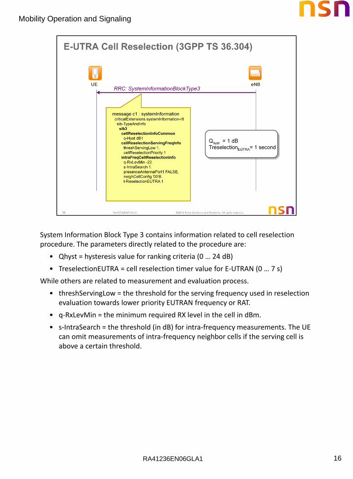
16
System Information Block Type 3 contains information related to cell reselection procedure. The parameters directly related to the procedure are:
• Qhyst = hysteresis value for ranking criteria (0 … 24 dB)
• TreselectionEUTRA = cell reselection timer value for E-UTRAN (0 … 7 s)
While others are related to measurement and evaluation process.
• threshServingLow = the threshold for the serving frequency used in reselection evaluation towards lower priority EUTRAN frequency or RAT.
• q-RxLevMin = the minimum required RX level in the cell in dBm.
• s-IntraSearch = the threshold (in dB) for intra-frequency measurements. The UE can omit measurements of intra-frequency neighbor cells if the serving cell is above a certain threshold.

RA41236EN06GLA1
Mobility Operation and Signaling
17
The System Information Block Type 4 contains neighboring cells information
• physCellId = physical-layer cell identity of neighbor cells.
• Qoffset = the offset value used for cell reselection process between serving and neighbor cells (-24 … 24 dB)

RA41236EN06GLA1
Mobility Operation and Signaling
18
The figure illustrates the cell reselection process based on parameters from SystemInformationBlockType3 and SystemInformationBlockType4 above.

RA41236EN06GLA1
Mobility Operation and Signaling
19

RA41236EN06GLA1
Mobility Operation and Signaling
20
A Tracking Area (TA) is a defined group of cells which can be used by the MME to page idle UEs. Within a Tracking Area, a UE is associated with a single MME and S-GW. As it moves to a new Tracking Area, an idle UE must announce its new “location” to the serving MME. That process is called a Tracking Area Update (TAU).
Instead of using a single Tracking Area, the MME may supply a Tracking Area List to reduce the location update signaling from the UE. As long as the UE is located in any of the listed Tracking Areas, a Tracking Area Update is not necessary.

RA41236EN06GLA1
Mobility Operation and Signaling
21
A Tracking Area ID (TAI) uniquely identifies the tracking area for paging and location updates. The TAI consists of the Mobile Country Code (MCC), Mobile Network Code (MNC), and Tracking Area Code (TAC). The graphic shows a Tracking Area consisting of two eNodeBs supporting five cells.
Together, the MCC and MNC identify the carrier’s PLMN identity. A Tracking Area (and TA Code) may be shared by more than one carrier. In that case, each carrier will identify the Tracking Area with its MCC and MNC values.
Mobile Country Code – 3 binary-coded decimal digits which uniquely identify the network operator’s country.
Mobile Network Code – 3 binary-coded decimal digits which uniquely identify the network operator within a country
Tracking Area Code – 16-bit code which uniquely identifies the Tracking Area within the PLMN. If the Tracking Area is used by more than one PLMN, each carrier must use the same TAC.
RA41236EN06GLA1
Mobility Operation and Signaling
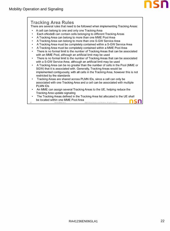
22
RA41236EN06GLA1
Mobility Operation and Signaling
23
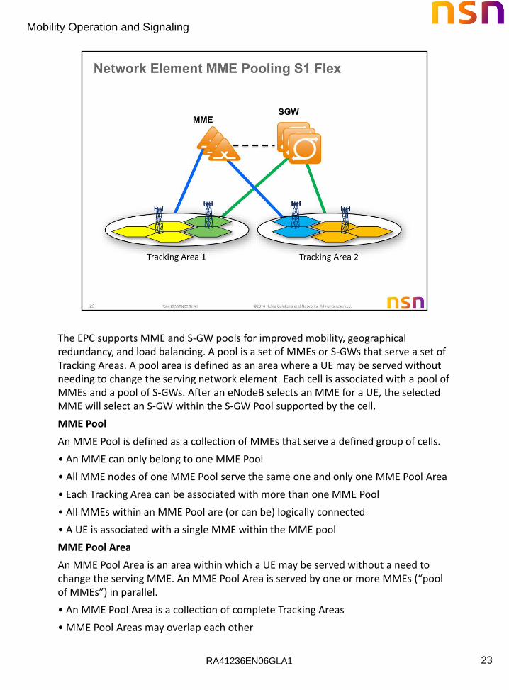
The EPC supports MME and S-GW pools for improved mobility, geographical redundancy, and load balancing. A pool is a set of MMEs or S-GWs that serve a set of Tracking Areas. A pool area is defined as an area where a UE may be served without needing to change the serving network element. Each cell is associated with a pool of MMEs and a pool of S-GWs. After an eNodeB selects an MME for a UE, the selected MME will select an S-GW within the S-GW Pool supported by the cell.
MME Pool
An MME Pool is defined as a collection of MMEs that serve a defined group of cells.
• An MME can only belong to one MME Pool
• All MME nodes of one MME Pool serve the same one and only one MME Pool Area
• Each Tracking Area can be associated with more than one MME Pool
• All MMEs within an MME Pool are (or can be) logically connected
• A UE is associated with a single MME within the MME pool
MME Pool Area
An MME Pool Area is an area within which a UE may be served without a need to change the serving MME. An MME Pool Area is served by one or more MMEs (“pool of MMEs”) in parallel.
• An MME Pool Area is a collection of complete Tracking Areas
• MME Pool Areas may overlap each other

RA41236EN06GLA1
Mobility Operation and Signaling
24
Serving Gateway (S-GW) Service Area
A S-GW Service Area is an area within which a UE may be served without a need to change the S-GW which is currently in use. An S-GW Service Area is served by one or more S-GWs at the same time.
• An S-GW Service Area is a collection of complete Tracking Areas associated with the S-GW Service Area
• S-GW Service Areas may overlap each other
S-GW Serving Area
• An S-GW serving area is served by one or more S-GWs acting in parallel (S-GW Pool)
• All S-GWs within an S-GW Pool are (or can be) logically connected
• A UE is associated with a single S-GW within the S-GW pool
Serving Gateway (S-GW) Pool
An S-GW Pool is a collection of S-GWs that serve an S-GW Service Area
• An S-GW can belong to only one S-GW Pool
• An S-GW Pool serves its associated S-GW Service Area
• Each cell can be associated with more than one S-GW Pool
• All S-GWs within an S-GW Pool are (or can be) connected for communication purposes
• An S-GW within one S-GW Pool can communicate with S-GWs in other S-GW Pools
• Connections between S-GWs within a pool or across pools are used for indirect packet forwarding
RA41236EN06GLA1
Mobility Operation and Signaling
25
RA41236EN06GLA1
Mobility Operation and Signaling
26
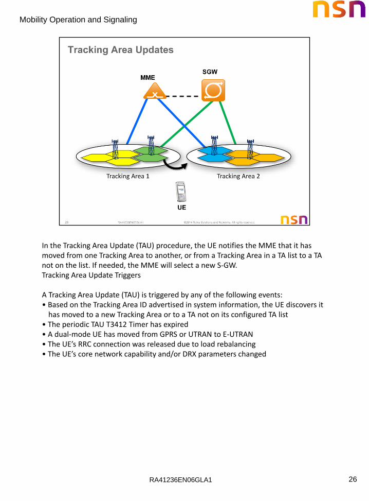
In the Tracking Area Update (TAU) procedure, the UE notifies the MME that it has moved from one Tracking Area to another, or from a Tracking Area in a TA list to a TA not on the list. If needed, the MME will select a new S-GW. Tracking Area Update Triggers A Tracking Area Update (TAU) is triggered by any of the following events: • Based on the Tracking Area ID advertised in system information, the UE discovers it
has moved to a new Tracking Area or to a TA not on its configured TA list • The periodic TAU T3412 Timer has expired • A dual-mode UE has moved from GPRS or UTRAN to E-UTRAN • The UE’s RRC connection was released due to load rebalancing • The UE’s core network capability and/or DRX parameters changed

RA41236EN06GLA1
Mobility Operation and Signaling
27
A successful Tracking Area Update (TAU) procedure is completed by 3-way handshake NAS messages:
1. TRACKING AREA UPDATE REQUEST
2. TRACKING AREA UPDATE ACCEPT
3. TRACKING AREA UPDATE COMPLETE
“EPS update type” field in the TRACKING AREA UPDATE REQUEST message inform the TAU type (e.g. TA updating, periodic updating etc.) as specified in TS 24.301
Depending on the update type, the fields on TRACKING AREA UPDATE ACCEPT may vary (e.g. new TAI list, new T3412 value etc.)

RA41236EN06GLA1
Mobility Operation and Signaling
28
RA41236EN06GLA1
Mobility Operation and Signaling
29
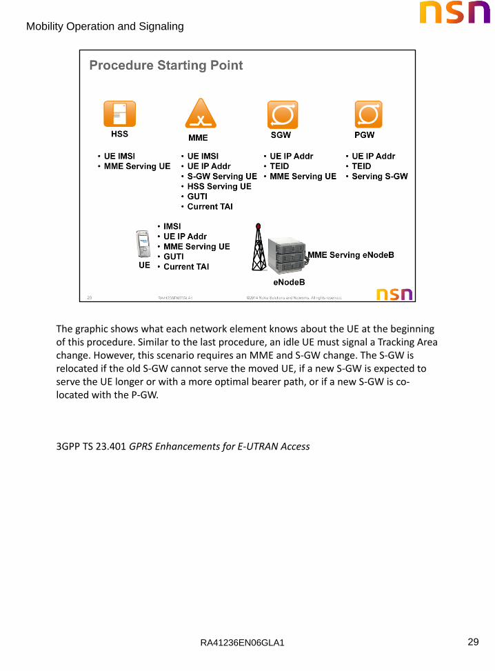
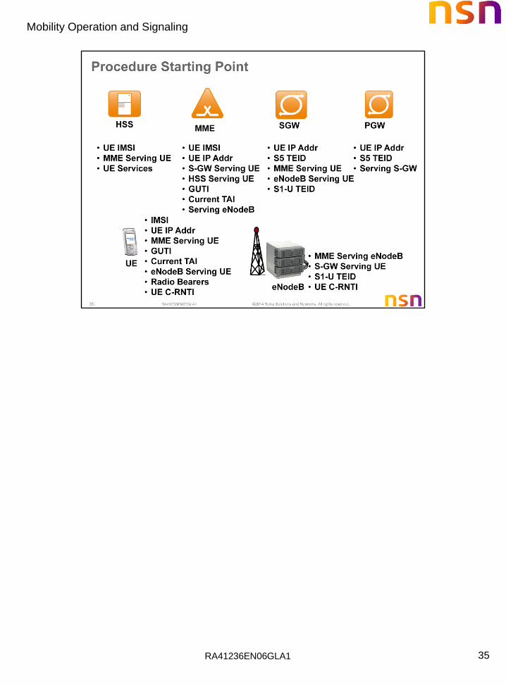
The graphic shows what each network element knows about the UE at the beginning of this procedure. Similar to the last procedure, an idle UE must signal a Tracking Area change. However, this scenario requires an MME and S-GW change. The S-GW is relocated if the old S-GW cannot serve the moved UE, if a new S-GW is expected to serve the UE longer or with a more optimal bearer path, or if a new S-GW is co-located with the P-GW.
3GPP TS 23.401 GPRS Enhancements for E-UTRAN Access
RA41236EN06GLA1
Mobility Operation and Signaling
30
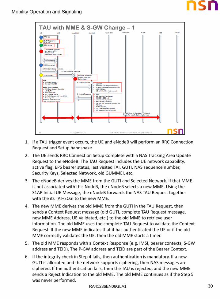
1. If a TAU trigger event occurs, the UE and eNodeB will perform an RRC Connection Request and Setup handshake.
2. The UE sends RRC Connection Setup Complete with a NAS Tracking Area Update Request to the eNodeB. The TAU Request includes the UE network capability, active flag, EPS bearer status, last visited TAI, GUTI, NAS sequence number, Security Keys, Selected Network, old GUMMEI, etc.
3. The eNodeB derives the MME from the GUTI and Selected Network. If that MME is not associated with this NodeB, the eNodeB selects a new MME. Using the S1AP Initial UE Message, the eNodeB forwards the NAS TAU Request together with the its TAI+ECGI to the new MME.
4. The new MME derives the old MME from the GUTI in the TAU Request, then sends a Context Request message (old GUTI, complete TAU Request message, new MME Address, UE Validated, etc.) to the old MME to retrieve user information. The old MME uses the complete TAU Request to validate the Context Request. If the new MME indicates that it has authenticated the UE or if the old MME correctly validates the UE, then the old MME starts a timer.
5. The old MME responds with a Context Response (e.g. IMSI, bearer contexts, S-GW address and TEID). The P-GW address and TEID are part of the Bearer Context.
6. If the integrity check in Step 4 fails, then authentication is mandatory. If a new GUTI is allocated and the network supports ciphering, then NAS messages are ciphered. If the authentication fails, then the TAU is rejected, and the new MME sends a Reject Indication to the old MME. The old MME continues as if the Step 5 was never performed.

RA41236EN06GLA1
Mobility Operation and Signaling
31
7. The new MME decides whether to relocate the S-GW or not. If a new S-GW is selected, the new MME sends a Context ACK (S-GW Change Indication) message to the old MME. The old MME marks in its context that the information in the S-GW, P-GW, and HSS must be updated.
8. Using the UE context received from the old MME, the new MME constructs a Mobility Management (MM) context for the UE. The new MME releases any network resources related to EPS bearers that are not active in the UE. If no default bearer context exists, the MME rejects the TAU Request. If a new S-GW was selected, the MME sends a GTP-C Create Bearer Request (IMSI, bearer contexts, MME Context ID, Type, Protocol Type over S5/S8) message to the new S-GW. Type instructs the S-GW to send Update Bearer Request the P-GW. Protocol Type over S5/S8 tells the S-GW which IP mobility protocol should be used over the S5/S8 interface.
9. The new S-GW sends the GTP-C Modify Bearer Request (S-GW address, S-GW TEID) to the P-GW.
10. PCEF Initiated IP-CAN Session Modification, If the PCRF response leads to an EPS bearer modification the P-GW should initiate a bearer update procedure.
11. The P-GW updates the bearer contexts and returns GTP-C Modify Bearer Response (P-GW address, TEIDs, etc.).
12. The S-GW updates its bearer context. The S-GW is now able to route bearer PDUs from the eNodeB to the P-GW. The S-GW returns a GTP-C Create Bearer Response to the new MME.

RA41236EN06GLA1
Mobility Operation and Signaling
32
13. The new MME verifies whether it holds subscription data for the UE identified
by the GUTI. If there are no subscription data in the new MME for this UE then the new MME sends a Diameter Update Location (Update Type) message to the HSS. Update Type instructs the HSS to update the MME registration, and whether the HSS should cancel the UE location in the old MME.
14. The HSS sends the Diameter Cancel Location (IMSI, Cancellation Type) message to the old MME with Cancellation Type set to Update Procedure.
15. The old MME acknowledges with the Diameter Cancel Location Ack (IMSI) message. When the timer started in step 5 expires, the old MME removes the UE’s MM context. (The timer ensures that the MM context is kept in the old MME in case the UE initiates another TAU procedure before completing the ongoing TAU procedure.)
16. The HSS acknowledges the Update Location message by sending a Diameter Update Location Answer to the new MME.
17. S1-AP DL NAS Transport including IMSI and subscription data
18. RRC DL information transfer to Ue including GUTI, TAI list, EPS bearer status, Security Context.
If a GUTI was included in the TAU Accept, the UE returns a NAS TAU Complete message to the MME. If the UE is in idle mode, the MME will release any signaling resources with the UE.
RA41236EN06GLA1
Mobility Operation and Signaling
33
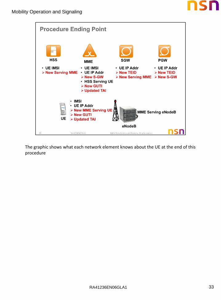
The graphic shows what each network element knows about the UE at the end of this procedure

RA41236EN06GLA1
Mobility Operation and Signaling
34
RA41236EN06GLA1
Mobility Operation and Signaling
35
RA41236EN06GLA1
Mobility Operation and Signaling
36
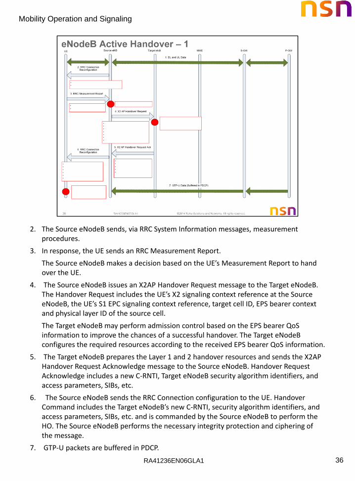
2. The Source eNodeB sends, via RRC System Information messages, measurement procedures.
3. In response, the UE sends an RRC Measurement Report.
The Source eNodeB makes a decision based on the UE’s Measurement Report to hand over the UE.
4. The Source eNodeB issues an X2AP Handover Request message to the Target eNodeB. The Handover Request includes the UE’s X2 signaling context reference at the Source eNodeB, the UE’s S1 EPC signaling context reference, target cell ID, EPS bearer context and physical layer ID of the source cell.
The Target eNodeB may perform admission control based on the EPS bearer QoS information to improve the chances of a successful handover. The Target eNodeB configures the required resources according to the received EPS bearer QoS information.
5. The Target eNodeB prepares the Layer 1 and 2 handover resources and sends the X2AP Handover Request Acknowledge message to the Source eNodeB. Handover Request Acknowledge includes a new C-RNTI, Target eNodeB security algorithm identifiers, and access parameters, SIBs, etc.
6. The Source eNodeB sends the RRC Connection configuration to the UE. Handover Command includes the Target eNodeB’s new C-RNTI, security algorithm identifiers, and access parameters, SIBs, etc. and is commanded by the Source eNodeB to perform the HO. The Source eNodeB performs the necessary integrity protection and ciphering of the message.
7. GTP-U packets are buffered in PDCP.

RA41236EN06GLA1
Mobility Operation and Signaling
37
The UE detaches from the Source eNodeB and synchronizes to the Target eNodeB. At this point the UE no longer has radio resources with the Source eNodeB.
8. The Source eNodeB sends the X2AP SN Status Transfer message to the Target
eNodeB to convey the PDCP DL and UL sequence numbers for the UE’s bearers. The Source and Target eNodeBs set up the X2 user plane tunnel. The Source eNodeB will now forward DL UE traffic to the Target eNodeB. The DL packets are buffered in the Target eNodeB.
9 . The UE sends a Random Access Preamble to the Target eNodeB.
10. The Target eNodeB returns a MAC Random Access Response (RAR) containing an UL grant and Timing Advance (TA).
11. The UE sends the connection Reconfig Complete message along with a MAC Buffer Status Report indicating the pending UL traffic in the UE. The Target eNodeB can now begin sending DL data to the UE.
12. The Target eNodeB sends an S1AP Path Switch message to the MME to signal that the UE has changed cells.
13. The MME sends a GTP-C User Plane Modify Bearer Request (eNodeB address and TEIDs for the EPS bearers) message to the serving S-GW.

RA41236EN06GLA1
Mobility Operation and Signaling
38
The S-GW switches the DL data path to the Target eNodeB. The S-GW may start sending DL packets to the Target eNodeB using the newly received address and TEIDs. However, the Target eNodeB will buffer any packets received over the new S1-U bearer path. The S-GW sends one or more "end marker" packets on the old path to the Source eNodeB and then releases any resources towards the Source eNodeB.
14. The S-GW sends a GTP-C User Plane Modify Bearer Response message to the MME.
15. The MME confirms the Path Switch Request (Step x) message with the S1AP Path Switch Request ACK message.
16. The Target eNodeB sends the X2AP UE Context Release message to inform the Source eNodeB that the handover was successful.
17. The Source eNodeB will flush its DL buffer and continue to deliver any in-transit packets. When finished, the Source eNodeB forwards the end marker packets to the Target eNodeB. All DL packets (except the end marker packets) are forwarded from the Target eNodeB to the Ue. After receiving the end marker packets, the Target eNodeB sends an X2AP Release Resource message to the Source eNodeB. Upon receiving the X2AP Release Resources message, the Source eNodeB will release any resources associated with the UE.

RA41236EN06GLA1
Mobility Operation and Signaling
39
RA41236EN06GLA1
Mobility Operation and Signaling
40
RA41236EN06GLA1
Mobility Operation and Signaling
41
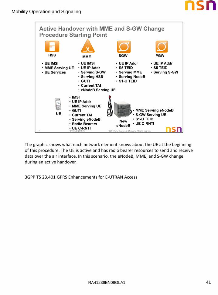
The graphic shows what each network element knows about the UE at the beginning of this procedure. The UE is active and has radio bearer resources to send and receive data over the air interface. In this scenario, the eNodeB, MME, and S-GW change during an active handover.
3GPP TS 23.401 GPRS Enhancements for E-UTRAN Access

RA41236EN06GLA1
Mobility Operation and Signaling
42
The inter eNodeB handover with MME relocation procedure is used to relocate the MME only, or both the MME and the S-GW. The procedure is initiated in the source eNodeB which also selects the target MME. The MME will not be relocated during inter-eNodeB handover unless the UE leaves the MME Pool Area where the UE is served. If the target MME determines the S-GW needs to be relocated, then it is selected by the target MME. The source eNodeB decides which of the EPS bearers are subject for forwarding of packets from the source eNodeB to the target eNodeB. The EPC does not change the decisions taken by the RAN node. Packet forwarding can take place either directly from the source eNodeB to the target eNodeB, or indirectly from the source eNodeB to the target eNodeB via the source and target S-GWs (or if the S-GW is not relocated, only the single S-GW). The availability of a direct forwarding path is determined in the source eNodeB and indicated to the source MME. If X2 connectivity is available between the source and target eNodeBs, a direct forwarding path is available. If a direct forwarding path is not available, indirect forwarding may be used. The MMEs (source and target) use configuration data to determine whether indirect forwarding paths are to be established. Depending on configuration data, the source MME determines and indicates to the target MME whether indirect forwarding paths should be established. Based on this indication and on its configuration data, the target MME determines whether indirect forwarding paths are established.
RA41236EN06GLA1
Mobility Operation and Signaling
43
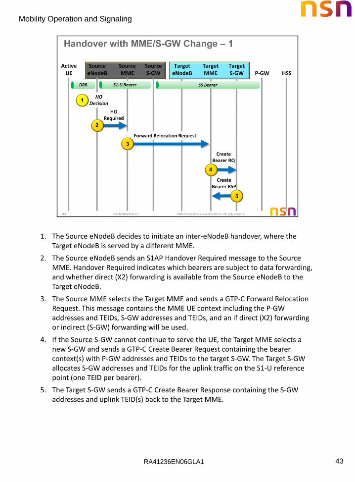
1. The Source eNodeB decides to initiate an inter-eNodeB handover, where the Target eNodeB is served by a different MME.
2. The Source eNodeB sends an S1AP Handover Required message to the Source MME. Handover Required indicates which bearers are subject to data forwarding, and whether direct (X2) forwarding is available from the Source eNodeB to the Target eNodeB.
3. The Source MME selects the Target MME and sends a GTP-C Forward Relocation Request. This message contains the MME UE context including the P-GW addresses and TEIDs, S-GW addresses and TEIDs, and an if direct (X2) forwarding or indirect (S-GW) forwarding will be used.
4. If the Source S-GW cannot continue to serve the UE, the Target MME selects a new S-GW and sends a GTP-C Create Bearer Request containing the bearer context(s) with P-GW addresses and TEIDs to the target S-GW. The Target S-GW allocates S-GW addresses and TEIDs for the uplink traffic on the S1-U reference point (one TEID per bearer).
5. The Target S-GW sends a GTP-C Create Bearer Response containing the S-GW addresses and uplink TEID(s) back to the Target MME.
RA41236EN06GLA1
Mobility Operation and Signaling
44
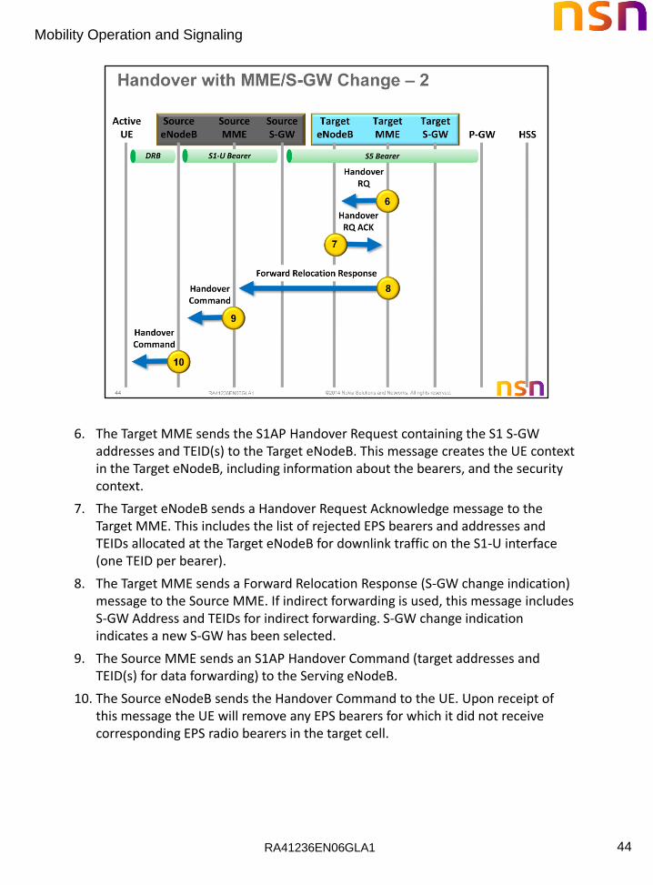
6. The Target MME sends the S1AP Handover Request containing the S1 S-GW addresses and TEID(s) to the Target eNodeB. This message creates the UE context in the Target eNodeB, including information about the bearers, and the security context.
7. The Target eNodeB sends a Handover Request Acknowledge message to the Target MME. This includes the list of rejected EPS bearers and addresses and TEIDs allocated at the Target eNodeB for downlink traffic on the S1-U interface (one TEID per bearer).
8. The Target MME sends a Forward Relocation Response (S-GW change indication) message to the Source MME. If indirect forwarding is used, this message includes S-GW Address and TEIDs for indirect forwarding. S-GW change indication indicates a new S-GW has been selected.
9. The Source MME sends an S1AP Handover Command (target addresses and TEID(s) for data forwarding) to the Serving eNodeB.
10. The Source eNodeB sends the Handover Command to the UE. Upon receipt of this message the UE will remove any EPS bearers for which it did not receive corresponding EPS radio bearers in the target cell.
RA41236EN06GLA1
Mobility Operation and Signaling
45
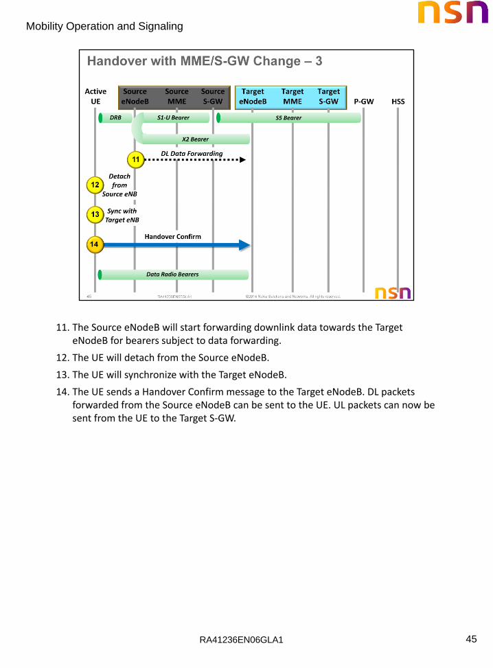
11. The Source eNodeB will start forwarding downlink data towards the Target eNodeB for bearers subject to data forwarding.
12. The UE will detach from the Source eNodeB.
13. The UE will synchronize with the Target eNodeB.
14. The UE sends a Handover Confirm message to the Target eNodeB. DL packets forwarded from the Source eNodeB can be sent to the UE. UL packets can now be sent from the UE to the Target S-GW.

RA41236EN06GLA1
Mobility Operation and Signaling
46
15. The Target eNodeB sends a Handover Notify message to the Target MME.
16. The Target MME sends Forward Relocation Complete to the Source MME.
17. The Source MME returns a Forward Relocation Complete Ack to the Target MME. A timer in the Source MME is started to supervise when resources in the Source eNodeB and Source S-GW will be released.
18. The Target MME sends an Update Bearer Request message to the Target S-GW. Modify Bearer Request contains the eNodeB addresses and TEIDs allocated at the Target eNodeB for DL traffic on S1–U for the accepted EPS bearers, and the P-GW address and TEIDs for UL traffic.

RA41236EN06GLA1
Mobility Operation and Signaling
47
19. If the S-GW is relocated, the Target S-GW assigns addresses and TEIDs (one per bearer) for DL traffic from the P-GW. It sends Modify Bearer Request to inform the P-GW of the S-GW and TEID(s) changes. If the S-GW is not relocated, no message is sent in this step and DL packets from the S-GW are immediately sent on to the Target eNodeB.
20. The P-GW updates its context field and returns Modify Bearer Response (P-GW address and TEID, MSISDN, etc.) to the Target S-GW. The P-GW starts sending DL packets to the Target S-GW using the newly received address and TEIDs.
21. The Target S-GW sends Modify Bearer Response (P-GW addresses and TEIDs at the P-GW for uplink traffic) to the Target MME.
RA41236EN06GLA1
Mobility Operation and Signaling
48
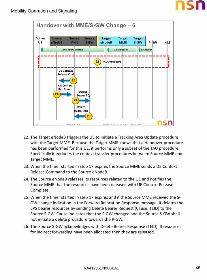
22. The Target eNodeB triggers the UE to initiate a Tracking Area Update procedure with the Target MME. Because the Target MME knows that a Handover procedure has been performed for this UE, it performs only a subset of the TAU procedure. Specifically it excludes the context transfer procedures between Source MME and Target MME.
23. When the timer started in step 17 expires the Source MME sends a UE Context Release Command to the Source eNodeB.
24. The Source eNodeB releases its resources related to the UE and notifies the Source MME that the resources have been released with UE Context Release Complete.
25. When the timer started in step 17 expires and if the Source MME received the S-GW change indication in the Forward Relocation Response message, it deletes the EPS bearer resources by sending Delete Bearer Request (Cause, TEID) to the Source S-GW. Cause indicates that the S-GW changed and the Source S-GW shall not initiate a delete procedure towards the P-GW.
26. The Source S-GW acknowledges with Delete Bearer Response (TEID). If resources for indirect forwarding have been allocated then they are released.

RA41236EN06GLA1
Mobility Operation and Signaling
49
The graphic shows what each network element knows about the UE at the end of this procedure

RA41236EN06GLA1
Mobility Operation and Signaling
50

RA41236EN06GLA1
Mobility Operation and Signaling
51
RA41236EN06GLA1
Mobility Operation and Signaling
52

RA41236EN06GLA1
Mobility Operation and Signaling
53

RA41236EN06GLA1
Mobility Operation and Signaling
54
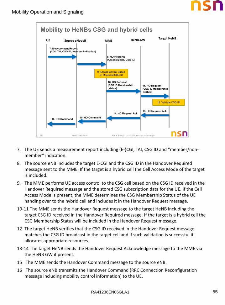
Mobility from eNB/HeNB to a HeNBs CSG/hybrid cell takes place with the S1 Handover procedure. In the following call flow the source cell can be an eNB or a HeNB. The procedure applies to any scenario where the CSG ID is provided by the UE or provided by the source eNB.
1. The source eNB configures the UE with proximity indication control.
2. The UE sends an “entering” proximity indication when it determines it may be near a cell (based on autonomous search procedures) whose CSG ID is in the UE’s CSG whitelist. The proximity indication includes the RAT and frequency of the cell.
3. If a measurement configuration is not present for the concerned frequency/RAT the source eNB configures the UE with relevant measurement configuration including measurement gaps as needed, so that the UE can perform measurements on the reported RAT and frequency. The network may also use the proximity indication to minimize the requesting of handover preparation information of CSG/hybrid cells by avoiding requesting such information when the UE is not in the geographical area where cells whose CSG IDs are in the UEs CSG White-list are located.
4. The UE sends a measurement report including the PCI (e.g., due to triggered event A3).
5. The source eNB configures the UE to perform SI acquisition and reporting of a particular PCI.
6. The UE performs SI acquisition using autonomous gaps, i.e., the UE may suspend reception and transmission with the source eNB within the limits defined in [TS 36.133] to acquire the relevant system information from the target HeNB.
RA41236EN06GLA1
Mobility Operation and Signaling
55
7. The UE sends a measurement report including (E-)CGI, TAI, CSG ID and “member/non-member” indication.
8. The source eNB includes the target E-CGI and the CSG ID in the Handover Required message sent to the MME. If the target is a hybrid cell the Cell Access Mode of the target is included.
9. The MME performs UE access control to the CSG cell based on the CSG ID received in the Handover Required message and the stored CSG subscription data for the UE. If the Cell Access Mode is present, the MME determines the CSG Membership Status of the UE handing over to the hybrid cell and includes it in the Handover Request message.
10-11 The MME sends the Handover Request message to the target HeNB including the target CSG ID received in the Handover Required message. If the target is a hybrid cell the CSG Membership Status will be included in the Handover Request message.
12 The target HeNB verifies that the CSG ID received in the Handover Request message matches the CSG ID broadcast in the target cell and if such validation is successful it allocates appropriate resources.
13-14 The target HeNB sends the Handover Request Acknowledge message to the MME via the HeNB GW if present.
15 The MME sends the Handover Command message to the source eNB.
16 The source eNB transmits the Handover Command (RRC Connection Reconfiguration message including mobility control information) to the UE.

RA41236EN06GLA1
Mobility Operation and Signaling
56

RA41236EN06GLA1
Mobility Operation and Signaling
57
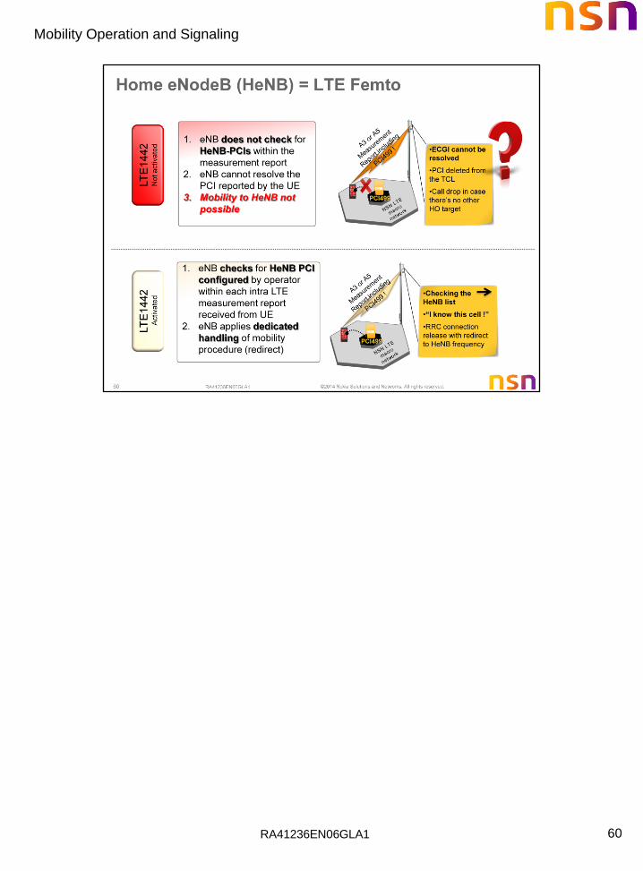
For release 10 of the specification no interface between the L-GW and the PCRF is specified and there is no support for Dedicated bearers on the PDN connection used for Local IP Access. The Local GW (L-GW) shall reject any UE requested bearer resource modification.
The direct user plane path between the HeNB and the collocated L-GW is enabled with a Correlation ID parameter that is associated with the default EPS bearer on a PDN connection used for Local IP Access. Upon establishment of the default EPS bearer the MME sets the Correlation ID equal to the PDN GW TEID (GTP-based S5) or the PDN GW GRE key (PMIP-based S5). The Correlation ID is then signaled by the MME to the HeNB as part of E-RAB establishment and is stored in the E-RAB context in the HeNB. The Correlation ID is used in the HeNB for matching the radio bearers with the direct user plane path connections from the collocated L-GW.
LIPA is supported for APNs that are valid only when the UE is connected to a specific CSG. LIPA is also supported for "conditional" APNs that can be authorized to LIPA service when the UE is using specific CSG. APNs marked as "LIPA prohibited" or without a LIPA permission indication cannot be used for LIPA. MME shall release a LIPA PDN connection to an APN if it detects that the UE's LIPA CSG authorization data for this APN has changed and the LIPA PDN connection is no longer allowed in the current cell.
As mobility of the LIPA PDN connection is not supported in release 10 of the specification, the LIPA PDN connection shall be released when the UE moves away from H(e)NB.

RA41236EN06GLA1
Mobility Operation and Signaling
58
RA41236EN06GLA1
Mobility Operation and Signaling
59
RA41236EN06GLA1
Mobility Operation and Signaling
60

RA41236EN06GLA1
Mobility Operation and Signaling
61
RA41236EN06GLA1
Mobility Operation and Signaling
62

RA41236EN06GLA1
Mobility Operation and Signaling
63
RA41236EN06GLA1
Mobility Operation and Signaling
64