0430 power/electronics replacement - umass amherst · jun 2001 mainframe 3 of 26 agilent 6890 gas...
TRANSCRIPT
430 Power/Electronics Replacement
Replacing the main board
WARNING Before proceeding, turn off the main power switch and unplug the power cord.
Caution Make sure you are properly grounded with an ESD strap before continuing.
The main printed circuit board in the 6890 GC is mounted on a metal carrier bracket on the right side of the instrument. The board and the bracket are replaced as an assembly.
1. If any external detectors are installed on the right side of the instrument through the large cut out on the main board, disconnect them now.
2. Remove any detector interface boards (P1, P2) from the main board.
3. Disconnect the cables from the following connectors:
J7 AC Power
J8 Integrated ALS PCB (6890 Plus only)
P3 EPC Board
P11 Display
P12 Keyboard
P13 Keyboard
P16 Oven sensor
P17 Oven door switch
P18 Inlet fan, oven flap, oven cryo
1 of 26Jun 2001 Mainframe
Agilent 6890 Gas Chromatograph Service Manual
430 Power/Electronics ReplacementReplacing the main board
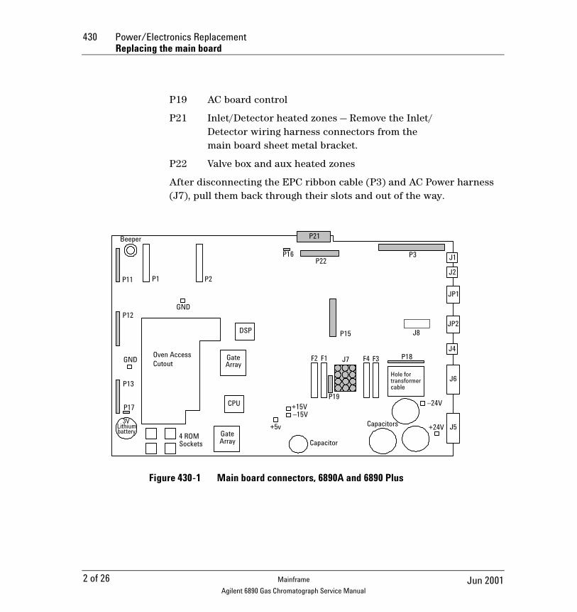
P19 AC board control
P21 Inlet/Detector heated zones — Remove the Inlet/Detector wiring harness connectors from the main board sheet metal bracket.
P22 Valve box and aux heated zones
After disconnecting the EPC ribbon cable (P3) and AC Power harness (J7), pull them back through their slots and out of the way.
Figure 430-1 Main board connectors, 6890A and 6890 Plus
Hole for transformer
Oven AccessCutout
Beeper
P11 P2
P12
P13
P17
P15DSP
GateArray
CPU
GND
4 ROMSockets
3VLithiumbattery Gate
Array
P16
P21
P22P3 J1
J2
JP1
JP2
J4
J6
J5
F2 F1 F4 F3 P18
+24V
–24V+15V–15V
+5v
Capacitor
Capacitors
cable
J8
GND
P1
J7
P19
2 of 26 Jun 2001Mainframe
Agilent 6890 Gas Chromatograph Service Manual

Power/Electronics Replacement 430Replacing the main board
Figure 430-2 Main board connectors, 6890N
4. Unplug any cables from the connectors on the back of the instrument.
5. If any valve actuators were installed, unclip the wiring harness from each actuator and pull the connectors out of the actuator bracket.
6. Remove the two screws securing the actuator bracket and remove the bracket.
-24V-15VGND
+24V+15V+5V
-10V REF GND
P2
F4 F5
P11
P12
P13
P1 P2 P21 P3
P22
P18
J7
P16
P19
P17
P4
P5
P6
J1
J2
JP1
J4
J6
P14
3 of 26Jun 2001 Mainframe
Agilent 6890 Gas Chromatograph Service Manual
430 Power/Electronics ReplacementReplacing the main board
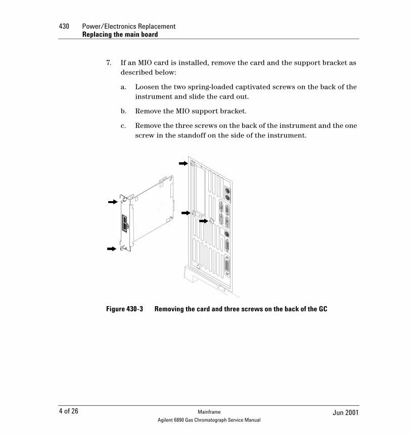
7. If an MIO card is installed, remove the card and the support bracket as described below:
a. Loosen the two spring-loaded captivated screws on the back of the instrument and slide the card out.
b. Remove the MIO support bracket.
c. Remove the three screws on the back of the instrument and the one screw in the standoff on the side of the instrument.
Figure 430-3 Removing the card and three screws on the back of the GC
4 of 26 Jun 2001Mainframe
Agilent 6890 Gas Chromatograph Service Manual

Power/Electronics Replacement 430Replacing the main board
Figure 430-4 Removing the MIO support bracket and jumper card
d. Pull out the MIO jumper card (P15) from the main board.
8. Remove the three 1/4-inch hex screws and the two Torx T-20 grounding screws holding the board to the instrument body.
Remove
Jumper card
Standoff
5 of 26Jun 2001 Mainframe
Agilent 6890 Gas Chromatograph Service Manual

430 Power/Electronics ReplacementReplacing the main board
Figure 430-5 Screw locations on the main board (6890A/Plus board shown. 6890N is the same.)
9. Holding the main board by the metal bracket at the top left and the capacitors at the bottom right, slide it slightly to the left and pull it out of the instrument being careful not to catch the board on any wiring harnesses.
10. Installation of the new board is the reverse of this procedure.
Caution Changing the board loses the GC serial number.
Cutout
Hole for transformer
Oven AccessCutout
Beeper
P11 P1 P2
P12
P13
P17
GND
P15DSP
GateArray
CPU
GND
4 ROMSockets
3VLithiumbattery Gate
Array
P16
P21
P22
P3
J1
J2
JP1
JP2
J4
J6
J5
F2 F1 F4 F3 P18
+24V
–24V+15V–15V
+5v
Capacitor
Capacitors
cable
J8
6 of 26 Jun 2001Mainframe
Agilent 6890 Gas Chromatograph Service Manual

Power/Electronics Replacement 430Installing an MIO card (6890A and 6890 Plus)
11. Re-configure the GC serial number. Press [Options], then select Diagnostic Instrument Status. Press [•] [•], type in the GC serial number (shown below the GC keypad), and press [Enter].
Installing an MIO card (6890A and 6890 Plus)
Two Modular Input/Output (MIO) cards are available for the 6890 GC. The INET card allows the 6890 GC to communicate and transmit data over an INET network to a Chemserver. The LAN communications interface card allows the 6890 GC to communicate and transmit data over a LAN to a Chemserver. While only one card can be installed at a time, the installation procedure is similar for either type of MIO card.
WARNING Before proceeding, turn off the main power switch and unplug the power cord.
Caution Make sure you are properly grounded with an ESD strap before continuing.
Follow the procedure below to install an MIO card:
1. Remove the electronics cover and the right side cover.
2. On the back of the GC, snip out the plastic plate that covers the MIO card slot. Discard the plate.
3. Remove the Torx T-10 screw located over the F2 fuse on the main board.
7 of 26Jun 2001 Mainframe
Agilent 6890 Gas Chromatograph Service Manual

430 Power/Electronics ReplacementInstalling an MIO card (6890A and 6890 Plus)
Figure 430-6 Location for MIO bracket standoff
4. Screw the hexagonal metal standoff provided with the MIO kit into the hole vacated by the T-10 screw. Use a 3/16-inch nut driver to tighten the standoff 1⁄8 turn past finger-tight.
5. Route the oven sensor wires (P16) and the main power wire harness (J7) underneath the standoff.
6. Plug the jumper board from the MIO kit into the P15 socket on the main board. Make sure the P7 connector on the jumper card points toward the back of the instrument.
7. From the back of the instrument, insert the metal bracket into the MIO card slot.
Hole for transformer
Oven AccessCutout
Beeper
P11 P1 P2
P12
P13
P17
GND
P15DSP
GateArray
CPU
GND
4 ROMSockets
3VLithiumbattery Gate
Array
P16
P21
P22P3 J1
J2
JP1
JP2
J4
J6
J5
F2 F1 F4 F3 P18
+24V
–24V+15V–15V
+5v
Capacitor
Capacitors
cable
J8
8 of 26 Jun 2001Mainframe
Agilent 6890 Gas Chromatograph Service Manual
Power/Electronics Replacement 430Installing an MIO card (6890A and 6890 Plus)
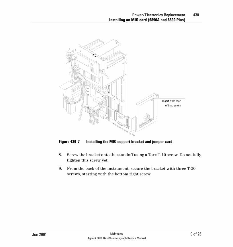
Figure 430-7 Installing the MIO support bracket and jumper card
8. Screw the bracket onto the standoff using a Torx T-10 screw. Do not fully tighten this screw yet.
9. From the back of the instrument, secure the bracket with three T-20 screws, starting with the bottom right screw.
Insert from rear
of instrument
9 of 26Jun 2001 Mainframe
Agilent 6890 Gas Chromatograph Service Manual
430 Power/Electronics ReplacementInstalling an MIO card (6890A and 6890 Plus)
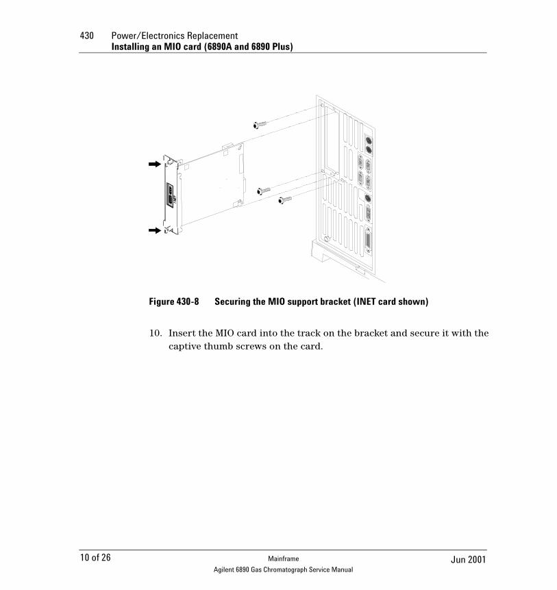
Figure 430-8 Securing the MIO support bracket (INET card shown)
10. Insert the MIO card into the track on the bracket and secure it with the captive thumb screws on the card.
10 of 26 Jun 2001Mainframe
Agilent 6890 Gas Chromatograph Service Manual
Power/Electronics Replacement 430Replacing ROMs on the main board (6890A and 6890 Plus)
Replacing ROMs on the main board (6890A and 6890 Plus)
WARNING Before proceeding, turn off the main power switch and unplug the power cord.
Caution Make sure you are properly grounded with an ESD strap before continuing.
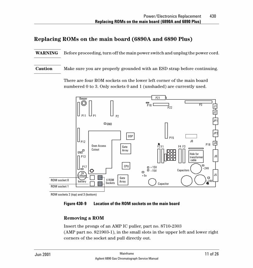
There are four ROM sockets on the lower left corner of the main board numbered 0 to 3. Only sockets 0 and 1 (unshaded) are currently used.
Figure 430-9 Location of the ROM sockets on the main board
Removing a ROM
Insert the prongs of an AMP IC puller, part no. 8710-2303 (AMP part no. 821903-1), in the small slots in the upper left and lower right corners of the socket and pull directly out.
Hole for transformer
Oven AccessCutout
Beeper
P11 P1 P2
P12
P13
P17
GND
P15DSP
GateArray
CPU
GND
4 ROMSockets
3VLithium
batteryGateArray
P16
P21
P22P3 J1
J2
JP1
JP2
J4
J6
J5
F2 F1 F4 F3 P18
+24V
–24V+15V–15V
+5v
Capacitor
Capacitors
cable
J8
ROM socket 0
ROM socket 1
ROM sockets 2 (top) and 3 (bottom)
11 of 26Jun 2001 Mainframe
Agilent 6890 Gas Chromatograph Service Manual

430 Power/Electronics ReplacementReplacing ROMs on the main board (6890A and 6890 Plus)
Inserting a ROM
Caution Before inserting a ROM (new or used), make sure that all of the prongs are straight. Straighten any bent prongs with a small flat-blade screwdriver or a small pair of needle nosed pliers before continuing.
ROMs are supplied in sets of two:
• The lower part number goes in socket 0.• The higher part number ROM goes in socket 1.If the positions are reversed, the system will not boot up.
To insert a ROM, align the flattened corner of the chip with the upper right corner of the socket (a small dot and the word AMP mark it). Check to make sure all the prongs are aligned with their appropriate slots, then push the chip into the socket until it is firmly seated and level.
12 of 26 Jun 2001Mainframe
Agilent 6890 Gas Chromatograph Service Manual

Power/Electronics Replacement 430Replacing the battery
Replacing the battery
WARNING Before proceeding, turn off the main power switch.
Caution Make sure you are properly grounded with an ESD strap before continuing. Removing the battery while the instrument is unplugged erases all user entered setpoints, methods and sequences.
The 3V battery for the 6890 GC supplies the power to retain user entries in memory, such as programmed methods and sequences, in the event of a power failure or when the instrument is unplugged. The battery is located in the lower left corner of the main board.
To replace the battery, slide the battery down and pull the battery out of the bottom first.
Figure 430-10 Location of the battery on the main board
Hole forOven AccessCutout
Beeper
P11 P1 P2
P12
P13
P17
GND
P15DSP
GateArray
CPU
GND
4 ROMSockets
3VLithiumbattery Gate
Array
P16
P21
P22P3 J1
J2
JP1
JP2
J4
J6
J5
F2 F1 F4 F3 P18
+24V
–24V+15V–15V
+5v
Capacitor
Capacitors
J8
transformercable
13 of 26Jun 2001 Mainframe
Agilent 6890 Gas Chromatograph Service Manual
430 Power/Electronics ReplacementReplacing the pneumatics board
Replacing the pneumatics board
WARNING Before proceeding, turn off the main power switch and unplug the power cord.
Caution Make sure you are properly grounded with an ESD strap before continuing.
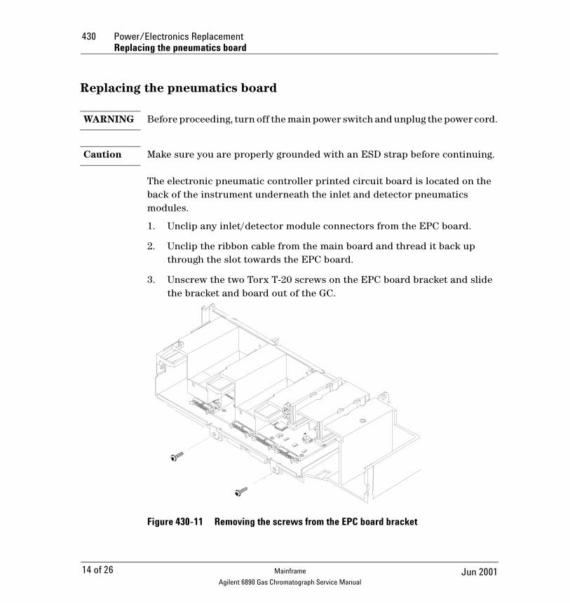
The electronic pneumatic controller printed circuit board is located on the back of the instrument underneath the inlet and detector pneumatics modules.
1. Unclip any inlet/detector module connectors from the EPC board.
2. Unclip the ribbon cable from the main board and thread it back up through the slot towards the EPC board.
3. Unscrew the two Torx T-20 screws on the EPC board bracket and slide the bracket and board out of the GC.
Figure 430-11 Removing the screws from the EPC board bracket
14 of 26 Jun 2001Mainframe
Agilent 6890 Gas Chromatograph Service Manual

Power/Electronics Replacement 430Replacing the pneumatics board
4. Reassembly is the reverse of removal.
Replacing the PCB bracket
The PCB bracket must be replaced when changing from a Type 1 auxiliary manifold to a Type 2 auxiliary manifold. See Installing a type 2 manifold, for more information.
1. Compare the PCB bracket under the pneumatics PC board with the one included in the accessory kit. Check for the differences in the three mounting screw tabs. If they are the same, proceed to the next section. If they are different, the existing bracket must be replaced with the new one.
WARNING Before proceeding, turn off the main power switch and unplug the power cord.
2. Remove the GC lower back panel.
Caution Make sure you are properly grounded with an ESD strap before continuing.
3. If an MIO card is present, remove it and the jumper card.
4. Disconnect all cables from the pneumatics PC board.
5. Trace the ribbon cable on the end of the board to the main board and disconnect it there. Feed the cable up through the PCB bracket to the top.
6. Remove the screws holding the PCB bracket and slide it and the board out of the GC.
7. Remove the eight screws that fasten the board to the PCB bracket. Transfer the board to the new bracket and secure it with the eight screws.
8. Slide the board and bracket assembly back into the GC. Use the 10 mm screw provided in the kit for the left-most position, on the side of the GC. Use the screws removed earlier for the other positions.
9. Pass the ribbon cable down through the slot in the PCB bracket and connect it to the main board. Reconnect all cables to the pneumatics board.
15 of 26Jun 2001 Mainframe
Agilent 6890 Gas Chromatograph Service Manual

430 Power/Electronics ReplacementReplacing the pneumatics board
10. Re-install the MIO card and the jumper card.
11. Re-install the lower back panel.
16 of 26 Jun 2001Mainframe
Agilent 6890 Gas Chromatograph Service Manual

Power/Electronics Replacement 430Replacing the transformer—GC serial number < 10225
Replacing the transformer—GC serial number < 10225
WARNING Before proceeding, turn off the main power switch and unplug the power cord.
Caution Make sure you are properly grounded with an ESD strap before continuing.
When you are facing the back of the instrument, you will see the transformer on the bottom, left side.
1. Unclip the transformer wiring harness from connector J7 on the main board.
2. Unclip the transformer wiring harness from connector J1 on the AC power board.
3. Unclip the connector from P9 on the AC power board and move the wires out of the way of the transformer.
17 of 26Jun 2001 Mainframe
Agilent 6890 Gas Chromatograph Service Manual

430 Power/Electronics ReplacementReplacing the transformer—GC serial number < 10225
Figure 430-12 Removing the transformer
4. Remove the four No. 2 Pozidriv screws from the top corners of the transformer.
WARNING The transformer is very heavy! Make sure you have a firm grip on the transformer before lifting it out of the instrument.
5. Lift out the transformer.
Remove mounting
screws (four corners)
18 of 26 Jun 2001Mainframe
Agilent 6890 Gas Chromatograph Service Manual

Power/Electronics Replacement 430Replacing the transformer—GC serial number ≥ 10225
Replacing the transformer—GC serial number ≥ 10225
WARNING Before proceeding, turn off the main power switch and unplug the power cord.
Caution Make sure you are properly grounded with an ESD strap before continuing.
When you are facing the back of the instrument, you will see the transformer on the bottom, left side.
1. Unclip the transformer wiring harness from connector J7 on the main board.
2. 6890A and 6890 Plus. Unclip the wires from J5 on the ALS Interface PCB, if installed.
6890N. Most 6890N transformers have a single cable going to connector J7 on the main board. A few early models have two cables; one goes to J7 and the other to an adapter (G1530-61590 Conversion Cable) that goes to the back of P1, the cable-end plug that connects to J7.
Figure 430-13 Some early 6890N transformers require a conversion cable for autosampler power
1 3
10 13
P7(connects to J7on main board)
Transformer
G1530-61590
19 of 26Jun 2001 Mainframe
Agilent 6890 Gas Chromatograph Service Manual

430 Power/Electronics ReplacementReplacing the transformer—GC serial number ≥ 10225
3. Unclip the transformer wiring harness from connector J1 on the AC power board.
4. Unclip the connector from P9 on the AC power board and move the wires out of the way of the transformer.
20 of 26 Jun 2001Mainframe
Agilent 6890 Gas Chromatograph Service Manual

Power/Electronics Replacement 430Replacing the transformer—GC serial number ≥ 10225
Figure 430-14 Removing the transformer
5. Remove the long bolt that secures the transformer.
WARNING The transformer is very heavy! Make sure you have a firm grip on the transformer before lifting it out of the instrument.
6. Lift out the transformer, gaskets, and plate. Save the gaskets.
To install a new transformer:
1. If you removed the bracket, install it over the PEM in the base of the GC. The open side of the bracket should face left, towards the main board.
2. Lay a gasket over the PEM, then loosely install the mounting bolt. Tighten only a few turns.
3. Install the transformer over the bolt. Once the transformer is in place, remove the bolt.
Remove mounting
bolt
Bracket
21 of 26Jun 2001 Mainframe
Agilent 6890 Gas Chromatograph Service Manual

430 Power/Electronics ReplacementReplacing the transformer—GC serial number ≥ 10225
4. Install the remaining gasket onto the transformer, then install the plate on the gasket.
5. Install the bolt and tighten.
22 of 26 Jun 2001Mainframe
Agilent 6890 Gas Chromatograph Service Manual

Power/Electronics Replacement 430Replacing the ALS Interface Board
Replacing the ALS Interface Board
The G2612A ALS Interface board is required to operate the 7683 Automatic Liquid Sampler. It can only be installed in a 6890 Plus Gas Chromatograph with a serial number >20,000. While an ALS Interface Board is installed in the GC, the GC can use only the 7683 ALS.
WARNING Before proceeding, turn off the main power switch and unplug the power cord.
Caution Make sure you are properly grounded with an ESD strap before continuing.
Follow the procedure below to replace the G2612A ALS Interface board.
1. Remove the GC rear panels and the right side cover.
2. If an MIO card (LAN card) is installed, loosen its two mounting screws and slide the card out of the instrument as shown below.
Figure 430-15 Removing the card from the GC
23 of 26Jun 2001 Mainframe
Agilent 6890 Gas Chromatograph Service Manual

430 Power/Electronics ReplacementReplacing the ALS Interface Board
3. Disconnect the 6890 Controller PCB Cable, part no. G2612-60510, from the ALS Interface board at P5. See Figure 430-16 and Figure 430-17. If you are replacing this cable, disconnect it from the main board at J8.
Figure 430-16 ALS Interface board connectors
Figure 430-17 GC Main board
Battery
P2
P4
P3 F1
J5 P5 P1
J8
24 of 26 Jun 2001Mainframe
Agilent 6890 Gas Chromatograph Service Manual

Power/Electronics Replacement 430Replacing the ALS Interface Board
4. Remove the two screws that secure the board to the chassis. See Figure 430-18.
5. Gently pull the board out of the GC until the cutouts in the board line up with the locking tabs in the bracket. Tilt the board away from the GC until clear of the tabs, then remove. See Figure 430-18.
To re-install the board:
Caution Attempting to slide the entire board under the locking tab will damage the board’s components.
1. Hold the board upright and slightly angled as shown in Figure 430-18.
2. Place the board onto the mounting bracket.
3. Slide it into the bracket until the cutouts in the board are aligned with the locking tabs in the bracket.
4. Lay the board against the chassis then slide it in until it stops. The locking tabs should hold the board in place.
Figure 430-18 Install the ALS Interface board
5. Install screws
1. Hold board at angle
3. Align cutouts and tabs
2. Place board in
bracket
25 of 26Jun 2001 Mainframe
Agilent 6890 Gas Chromatograph Service Manual

430 Power/Electronics ReplacementReplacing the ALS Interface Board
5. Secure the board to the chassis using the two mounting screws. The board should not be stressed or bowed against the locking tab. See Figure 430-18.
6. Locate the 2-wire cable leading from the transformer and connect it to the ALS Interface board at J5. See Figure 430-18 and Figure 430-16.
7. Connect the 6890 Controller PCB Cable, part no. G2612-60510, to the ALS Interface board at P5. If replacing the cable, route the new cable through the cutout in the main board and connect it to J8. SeeFigure 430-16 and Figure 430-17.
8. If an MIO card was removed from the GC, re-install it.
9. Re-install the GC covers.
10. Restore power to the GC.
26 of 26 Jun 2001Mainframe
Agilent 6890 Gas Chromatograph Service Manual