04 tributary
DESCRIPTION
xgdhghTRANSCRIPT

7/18/2019 04 Tributary
http://slidepdf.com/reader/full/04-tributary-56d5f13716c0d 1/14
Tributary load Prof Schierle 1
Tributary Load and Load Path
Child horse post
rotating platform
supporting gear
Assume 1’ tributary

7/18/2019 04 Tributary
http://slidepdf.com/reader/full/04-tributary-56d5f13716c0d 2/14
Tributary load Prof Schierle 2
Load Path and
Tributary Load• Load path is the path load
travels from where it acts
to where it is resisted
• Tributary load is the load
acting on a member
(needed to design it)
It is convenient to visualize and
compute load on a strip of unit
width (1 foot or 1 meter)
For example:
• 1’ slab, resting on
• 1’ wall, resting on
• 1’ footing, resting on
• 1’ soil

7/18/2019 04 Tributary
http://slidepdf.com/reader/full/04-tributary-56d5f13716c0d 3/14
Tributary load Prof Schierle 3
Lateral wind load
Load path: A > B > C
• A wind wall• B floor and roof diaphragms
• C shear walls
Tributary load:
A Wind wall resists wind pressure
B Floor/roof diaphragms resist wind wall load
(½ of wall above & ½ of wall below)C Shear walls resist ½ each (2 walls) of
floor and roof diaphragms

7/18/2019 04 Tributary
http://slidepdf.com/reader/full/04-tributary-56d5f13716c0d 4/14
Tributary load Prof Schierle 4
Load Path1 Slab / wall
Slab rests on walls
2 Deck / joist / wall
Deck rests on joists
Joists rest on walls
3 Slab / beam / wallSlab rests on beams
Beams rest on walls
4 Deck / joist / beam / wallDeck rests on joists
Joists rest on beams
Beams rest on walls
5 Deck / joist / beam / girder / postDeck rests on joists
Joists rest on beams
Beams rest on girders
Girders rest on post (column) All supported by footing

7/18/2019 04 Tributary
http://slidepdf.com/reader/full/04-tributary-56d5f13716c0d 5/14
Tributary load Prof Schierle 5
Tributary load
Uniform loadw = 100 psf (pounds per square foot)
Post reactions
Ra = Rb = Rc = R
R = 100 x 12’ x 10’ / 4 = 3000 #R = 3000 # / 1000 R = 3.0 k
Note:
# = pound
k = kip (1 kip = 1000 pounds)
Point load
P = 8kPost reactions
Ra = Rb = Rc = R
R = 8 / 4 R = 2.0 k

7/18/2019 04 Tributary
http://slidepdf.com/reader/full/04-tributary-56d5f13716c0d 6/14Tributary load Prof Schierle 6
Tributary load
Simple beam on 2 columns
Assume:w = 200 plf (pounds per linear foot)
Reactions
Ra = Rb = R = w L/2R = 200 x 30 / 2 = 3000 #
R = 3000 #/ 1000 R = 3.0 k
Two simple beams on three columns
Assume:
w = 2 klf
ReactionsRa = 2 x 10 / 2 Ra = 10 k
Rb = 2 x (10+20) / 2 Rb = 30 k
Rc = 2x20 / 2 Rc = 20 k
7/18/2019 04 Tributary
http://slidepdf.com/reader/full/04-tributary-56d5f13716c0d 7/14Tributary load Prof Schierle 7
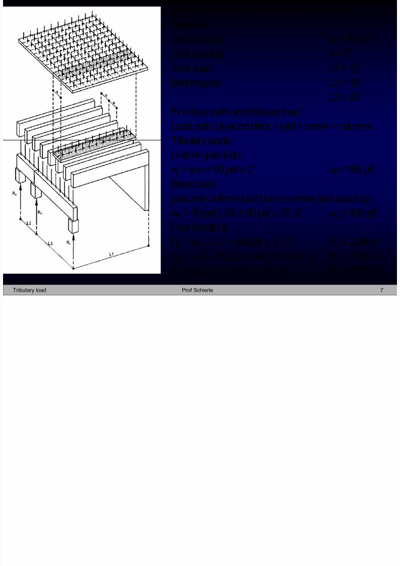
Tributary load: deck / joist / beam / column
Assume
Uniform load w = 80 psf
Joist spacing e = 2’Joist span L1 = 12’
Beam spans L2 = 10’
L3 = 20’
Find load path and tributary load
Load path: plywood deck > joist > beam > columns
Tributary loads:
Uniform joist loadw j = w e = 80 psf x 2’ w j = 160 plf
Beam load
(assume uniform load due to narrow joist spacing)
wb = 80 psf L1/2 = 80 psf x 12’ /2 wb = 480 plf
Post reactions
Ra = wbL2 / 2 = 480 plf x 10 /2 Ra = 2,400 #
Rb = wb (L2+L3)/2 = 480 (10+20) / 2 Rb = 7,200 #Rc = wb L3 / 2 = 480 x 20 / 2 Rc = 4,800 #

7/18/2019 04 Tributary
http://slidepdf.com/reader/full/04-tributary-56d5f13716c0d 8/14Tributary load Prof Schierle 8
Tributary load
Three-story building
1 Isometric view2 Exploded visualization
3 Dimensions
Wind wall > diaphragms > shear walls
AssumeWind pressure P = 20 psf
Shear wall shear (2 walls)
Third floor
V3 = 20 psf x 100’ x 5’/1000 V3 = 10 kSecond floor
V2 = 20 psf x 100’ x 15’/1000 V2 = 30 k
First floor = base shear V
V = 20 psf x 100’ x 25’/1000 V = 50 kNote:
Each diaphragm resists wind pressure from half the
wall above and below. Lower half of 1st floor resisted
by footing; hence shear walls don’t resist lower half.

7/18/2019 04 Tributary
http://slidepdf.com/reader/full/04-tributary-56d5f13716c0d 9/14Tributary load Prof Schierle 9
Tributary load
1 Concrete slab > wall
Concrete slab t = 8”, span L = 20’
LL = 50 psf DL =120 psf (150 pcf)
=170 psf
Slab load on wall (per linear foot of wall)
w = 170 psf x 20’/2 w =1700 plf
2 Deck > joist > wall
Plywood roof deck2x12 wood joists at 24”, span L = 18’
LL =30 psf
DL= 20 psf
= 50 psf
Roof load on wall (per linear foot of wall)
w = 50 psf x 18’/2 w = 450 plf

7/18/2019 04 Tributary
http://slidepdf.com/reader/full/04-tributary-56d5f13716c0d 10/14Tributary load Prof Schierle 10
Beam
P = 16 k
Tributary load
3 Concrete slab / beam / wall
Slab span L = 10’, t = 5”
Beam span L = 30’
LL = 20 psf
DL = 70 psf (including beam DL)
=90 psf
Beam load w = 90 psf x10’ / 1000 w = 0.9 klf
Wall reaction R = 0.9 klf x 30’ / 2 R = 13.5 k
4 Concrete slab on metal deck / joist/ beam
Deck span L = 8’
Joist span L = 20’
Beam span L = 40’LL = 40 psf
DL = 60 psf (including joist and beam DL)
=100 psf
Joist load w = 100 psf x 8’ / 1000 w = 0.8 klf Beam point loads P = 0.8 klf x 20’ P = 16 k
Beam reaction R = 4 P /2 = 4 x 16 k / 2 R = 32 k
Uniform wall load w = 100 psf x 4’ / 1000 w = 0.4 klf
Note:
Wall requires pilaster to support beams

7/18/2019 04 Tributary
http://slidepdf.com/reader/full/04-tributary-56d5f13716c0d 11/14Tributary load Prof Schierle 11
P=35k P=35k
Girder
Beam
7 x P=10k
Tributary load
Concrete slab on metal deck / joist/ beam / girder
Assume:
Spans:Deck L = 5’
Joist L = 20’
Beam L = 40’
Girder L = 60’
Loads:LL = 50 psf
DL = 50 psf (combined framing and deck load)
=100 psf
Uniform joist loadw = 100 psf x 5’/1000 w = 0.5 klf
Beam point loads (from joists)
P = 0.5 klf x 20’ P = 10 k
Girder point loads (from beams)P = 7 x 10 k/2 P = 35
Girder uniform load
w = 100 psf x 2.5’ / 1000 w = 0.25 klf
Column reaction
R=(100 psf/1000)x40’x60’/4 R = 60 k

7/18/2019 04 Tributary
http://slidepdf.com/reader/full/04-tributary-56d5f13716c0d 12/14Tributary load Prof Schierle 12
One-story concrete structure
Loads:
Roofing 3 psf
Ceiling 2 psf
10” concrete slab 125 psf (150 pcf x 10” / 12”)
DL 130 psf
LL 20 psf
150 psf
Lx = 30’
Lxc = 34
Ly = 25’
Columns, 12”x12” (t=12”, t/2 = 6” = 0.5’)
Column reactions A, B, C, D
Ra = 150 psf (30+34)/2 (25) Ra = 120,000 #
Rb = 150 (30+34)/2 (25/2+0.5) Rb = 62,400 #
Rc = 150 (30/2+0.5) (25) Rc = 58,125 #
Rd = 150 (30/2+0.5) (25/2+0.5) Rd = 30,225 #

7/18/2019 04 Tributary
http://slidepdf.com/reader/full/04-tributary-56d5f13716c0d 13/14Tributary load Prof Schierle 13
Level 2 column reactions w = 150 psf
Ra = 150 psf (30+34)/2 (25) = 150 (800) Ra = 120,000 #
Rb = 150 (30+34)/2 (25/2+1) = 150 (432) Rb = 64,800 #
Rc = 150 (30/2+1) (25) = 150 (400) Rc = 60,000 #
Rd = 150 (30/2+1) (25/2+1) = 150 (216) Rd = 32,400 #Level 1 reactions w=150+200 w = 350 psf
Ra = 350 (800) Ra = 280,000 #
Rb = 350 (432) Rb = 151,200 #
Rc = 350 (400) Rc = 140,000 #Rd = 350 (216) Rd = 75,600 #
Level 0 reactions w=150+200+200 w = 550 psf
Ra = 550 (800) Ra = 440,000 #
Rb = 550 (432) Rb = 237,600 #
Rc = 550 (400) Rc = 220,000 #
Rd = 550 (216) Rd = 118,800 #
Three-story concrete structure
Roof DL 130 psf
Roof LL 20 psf
Roof 150 psf
Floor DL 150 psf (includes columns, etc.)
Floor LL 50 psf (Office LL)
Floor 200 psf
Columns, 2’x2’ (t =2’, t/2 =1’)

7/18/2019 04 Tributary
http://slidepdf.com/reader/full/04-tributary-56d5f13716c0d 14/14Tributary load Prof Schierle 14
h p p y e n d