04 marine radar - university of rijeka · on ships having a gyro compass the display has a gyro...
TRANSCRIPT

1
04
THE MARINE RADAR
Basic terms
radar
tracking
range
bearing
target
reference source
echo
scanner
radar beam
indirect echo
side-lobe effect
radar range
scanning
display
cathode ray tube (CRT)
console
radar repeater
radarscope
scope
plan position indicator
(PPI)
LOP
true motion radar
relative motion radar
racon
CPA
TCPA
screen
presentation
bearing cursor
range
strobe
pip
readings
tuning of radar
errors
bearing resolution
range resolution
radar shadow
multiple echo
false echo
Radar is a word derived from "radio detection and ranging". It is of great practical
value to the navigator in the piloting waters. Radars are not only used to locate
navigational aids and to perform radar navigation, but they are also used for tracking
other vessels in the vicinity so as to avoid risk of collision.
Radar determines distance to an object by measuring the time required for a radio
signal to travel from a transmitter to the object and return. Such measurements can be
converted into lines of position (LOP’s) comprised of circles with radius equal to the
distance to the object. Since marine radars use directional antennae, they can also
determine an object’s bearing. However, due to its design, a radar’s bearing measurement
is less accurate than its distance measurement. Understanding this concept is crucial to
ensuring the optimal employment of the radar for safe navigation.

2
Insert the missing words
Radar is a word derived from "radio detection and __________". It is of great practical
value to the navigator in the __________ waters. Radars are not only used to locate
navigational aids and to perform radar navigation, but they are also used for __________
other vessels in the vicinity so as to avoid risk of collision.
Radar determines distance to an object by measuring the time required for a radio
signal to travel from a __________ to the object and return. Such measurements can be
converted into lines of __________ (LOP’s) comprised of circles with radius equal to the
distance to the object. Since marine radars use directional __________, they can also
determine an object’s bearing. However, due to its design, a radar’s __________
measurement is less accurate than its distance measurement.
The basic principle of radar is to determine the range to an object or "target" by
measuring the time required for an extremely short pulse of very high radio frequency,
transmitted as a radio wave, to travel from a reference source (own ship) to a target and
return as a reflected echo. The radar antenna (called the scanner) rotates to scan the entire
surrounding area. Bearings to the target are determined by the orientation of the antenna
at the moment when the reflected echo returns.
Supply the appropiate term
The basic principle of radar is to determine the radius/range/circle to an object or
"target" by measuring the time required for an extremely short post/pump/pulse of very
high radio frequency, transmitted as a radio wave, to travel from a reference source (own
ship) to a charge/target/place and return as a reflected echo. The radar antenna (called
the scanner) rotates to see/scan/screen the entire surrounding area. Bearings to the target
are determined by the orientation of the antenna at the moment when the reflected
signal/echo/sound returns.
Complete the text below
Marine Radar FURUNO 1832 : 4 kW output, 36 nm range 3 NMEA 0183 ports ( 2 inputs and 1 output) User-programmable function keys Automatic optimization of radar picture Newly enhanced short range performance Cursor position and radar system data output ( TTM target data with ARP-10) Head-up, Course-up, North-up and True Motion Economy Mode, Guard Zone Alarm and Watch Mode Optional Autoplotter ARP-10 ( 10 targets auto/ manual acquisition and auto tracking)

3
The basic principle of radar is to determine the ................... or "target" by measuring the
time required for an extremely short pulse of very high radio frequency, transmitted as a
radio wave, to travel from a reference source (own ship) to a target and return
........................... .
The radar antenna (called the __________ ) rotates to scan the entire surrounding area.
Bearings to the target are determined by the orientation of the antenna at the moment
when .......................... .
The radar incorporates a display device, i.e. a cathode ray tube located within a console
called a radar repeater. The most common of such displays is called the plan position
indicator scope, or PPI. Bearing on the PPI scope is indicated around the periphery of the
screen. On ships having a gyro compass the display has a gyro input and the presentation
is oriented so that the true north lies under the 000 degrees mark. Most radars are now
fitted with bearing cursors and range strobes. As the antenna rotates a thin line sweeps
around the center of the screen and illuminates or "paints" any objects within the range of
the radarscope. The presentation of objects is called a "pip" or "blip".
Insert the missing term
The radar incorporates a __________ , i.e. a cathode ray tube located within a console
called a radar __________ .
The most common of such displays is called the plan position indicator scope, or
__________.
Bearing on the PPI scope is indicated around the periphery of the __________.
On ships having a gyro compass the display has a gyro input and the presentation is
oriented so that the true __________ lies under the 000 degrees mark.
Most radars are now fitted with bearing cursors and range strobes.
As the antenna rotates a thin line sweeps around the center of the screen and illuminates
or "paints" any objects within the range of the __________.
The presentation of objects is called a "__________" or "blip".
Factors Affecting Radar Interpretation
• Radar’s value as a navigational aid depends on the navigator’s understanding its
characteristics and limitations. Whether measuring the range to a single reflective

4
object or trying to find a shoreline lost amid severe clutter, knowledge of the
characteristics of the individual radar used are crucial.
• Marine radars are usually short range radars that are used by ships to pinpoint
locations about other ships and land in the area. The frequencies with which these
radars are operated are known as x-band or s-band frequencies. The x stands for
secret, as the ship radar was mainly a hidden frequency while used for the purpose
of tracking ship during the Second World War. The s stands for small range in the
second type.
Complete the text below
• Radar’s value as a navigational aid depends on the navigator’s understanding its
................ and .................. .
• Whether measuring the range to a single reflective object or trying to
.......................... lost amid severe clutter, knowledge of the characteristics of the
individual radar used are crucial.
• Marine radars are usually short range radars that are used by ships to
.............................. about other ships and land in the area.
• The frequencies with which these radars are operated are known as x-band or s-
band ___________.
• The x stands for ___________ , as the ship radar was mainly a hidden frequency
while used for the purpose of tracking ship during the Second World War.
• The s stands for ........................ in the second type.
Radar Resolution
There are two important factors in radar resolution: bearing resolution and
range resolution.
Bearing Resolution
Bearing resolution is the ability of the radar to display as separate pips the
echoes received from two targets which are at the same range and close
together. It is proportional to the antenna length and reciprocally
proportional to the wavelength.
Supply the missing word
Radar Resolution
There are two important factors in radar ___________ : bearing resolution and
range resolution.
Bearing Resolution
Bearing resolution is the ability of the radar to display as separate pips the
___________ received from two targets which are at the same ___________ and close
together.

5
It is proportional to the antenna length and reciprocally proportional to the ___________.
Range Resolution
Range resolution is the ability to display as separate pips the echoes
received from two targets which are on the same bearing and close to each
other. This is determined by pulselength only. Practically, a 0.08
microsecond pulse offers the discrimination better than 25 meters as do so
with all Furuno radars.
Test targets for determining the range and bearing resolution are radar
reflectors having an echo area of 10 square meters.
Read the text below and separatae the words in each sentence
Range Resolution
Rangeresolutionistheabilitytodisplayasseparatepipstheechoes
receivedfromtwotargetswhichareonthesamebearingandclosetoeach
other.Testtargetsfordeterminingtherangeandbearingresolutionareradar
reflectorshavinganechoareaof10squaremeters.
Bearing Accuracy
One of the most important features of the radar is how accurately the
bearing of a target can be measured. The accuracy of bearing measurement
basically depends on the narrowness of the radar beam. However, the
bearing is usually taken relative to the ship’s heading, and thus, proper
adjustment of the heading marker at installation is an important factor in
ensuring bearing accuracy. To minimize error when measuring the bearing of
a target, put the target echo at the extreme position on the screen by selecting
a suitable range.
TRUE or FALSE?
Bearing Accuracy
• One of the most important features of the gyro compass is how accurately the bearing of a target can be measured.
• The accuracy of bearing measurement basically depends on how wide the radar
beam is.
• The bearing is usually taken relative to the ship’s course.
• So, proper adjustment of the heading marker at installation is an important factor
in ensuring range accuracy.
• To minimize error when measuring the bearing of a target, put the target echo at
the closest position on the screen by selecting a suitable range.
6
Discussion:
Work in pairs and discuss the above text using the questions above:
1. What are the main uses of marine radar?
2. Explain the basic principle of the radar function.
3. How does the radar determine distance to an object?
4. What do the directional antennae enable?
5. How are the bearings determined?
6. What is a PPI?
7. How is the presentation oriented in radars with the gyro input?
8. What happens on the radarscope as the antenna rotates?
9. Explain the concepts of difraction, attenuation and refraction.
10. What are the factors affecting the interpretation of the radar picture?
11. What is bearing resolution?
12. What is range resolution?
13. When do the radar shadows occur?
14. What is the cause of the multiple echo?
15. What are the two instances of false echoes?
16. What is the accuracy of the radar bearings and range?
17. Explain the difference between a true and relative motion radar.
18. Explain the difference between an x-band or s-band radar.
19. Why is tracking ships compulsory?

7

8

9
Part II.
Operation of the Marine Radars
The operation of the marine radars can be explained as follows:
• There is an antenna on the top of the radar that continuously rotates and flashes
• The flashes actually are frequency beams that are transmitted from the radar to
find out whether there any objects present in the path of the ship
• The frequency and the time taken by the flashes to return (reflections) to the radar
receiver of the ship helps to find out whether the route of the boat can be
continued with or not
• On the display screen, the reflections can be seen so that identifying the actual
distance of the objects can be even more easy

10
Interpretation of information on a radarscope
Interpretation of information on a radarscope is not always easy and requires much skill
of the radar operator to obtain correct readings. These are affected by unfavorable
meterological conditions, possible component failures, bad tuning errors.
Among the factors producing errors in interpretation are: bearing resolution,
range resolution, radar shadows, multiple echoes and false echoes.
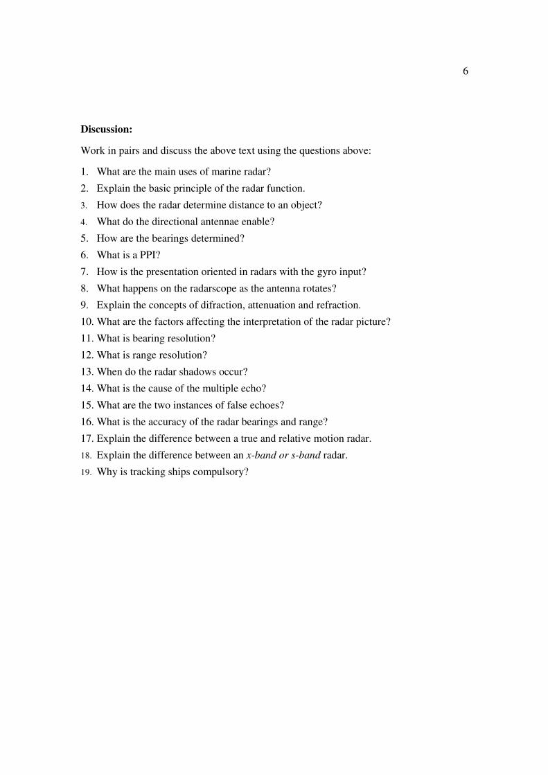
- Bearing resolution is the minimum difference in bearing between two targets at
same range which can be seen clearly. If two objects are close together their pips
may merge giving the impression of one target only. Such faulty presentations often
appear in coastal areas ("false shoreline").
- Range resolution is the minimum difference in range between two objects at the
same bearing to be clearly distinguished on the radar display. False interpretation may
occur if small boats or rocks are merged with the shoreline.
- Radar shadows occur when a large radar target masks another small object positioned
behind it or when an objeet is obscured by the curvature of the Earth.
- The multiple echo occurs when a radar beam bounces back and forth between the
ship and a relatively close-in target, i.e. another ship.
- A false echo is a type of false pip that appears on the display where there is actually
no target at all. It occurs when a part of the energy is reflected to the antenna from a
part of the ship's structure (indirect echo) or if energy from side lobes (in addition to
the main lobe of the radar beam) is reflected back by a target (side-lobe effect).
In piloting most radar bearings are accurate only to within 3 to 5 degrees. A well-
tuned radar gives ranges precise to within ±100 yards out to the radar horizon. Therefore
radar range LOP's are preferred over radar bearings.
In a true motion radar, one's own ship and other moving targets move on the PPI in
accordance with their true courses and speeds. All fixed targets appear as stationary
echoes. It needs own ship's speed and course input. In a relative motion radar the position
of one's own ship is usually fixed at the centre of the PPI, and all detected targets move
relative to one's own ship.
- Bearing resolution is the minimum difference in bearing between two targets at
same range which can be seen clearly. If two objects are close together their pips
may merge giving the impression of one target only. Such faulty presentations often
appear in coastal areas ("false shoreline").
- Range resolution is the minimum difference in range between two objects at the
same bearing to be clearly distinguished on the radar display. False interpretation may
occur if small boats or rocks are merged with the shoreline.
- Radar shadows occur when a large radar target masks another small object positioned
behind it or when an objeet is obscured by the curvature of the Earth.
- The multiple echo occurs when a radar beam bounces back and forth between the

11
ship and a relatively close-in target, i.e. another ship.
- A false echo is a type of false pip that appears on the display where there is actually
no target at all. It occurs when a part of the energy is reflected to the antenna from a
part of the ship's structure (indirect echo) or if energy from side lobes (in addition to
the main lobe of the radar beam) is reflected back by a target (side-lobe effect).
Basic Block Diagram of a Radar
A PPI Radarscope, with Range Rings Illuminated
12
Tug and Tow Merged Because
of Lack of Range Resolution
A False Shoreline Caused
by Lack of Bearing Resolution

13
IMO STANDARD MARINE COMMUNICATION PHRASES
III/6.2.2 - NAVIGATIONAL ASSISTANCE SERVICE
6.2.2.1 - Request, identification, begin and end
Is shore based radar assistance available?
- Yes, shore based radar assistance available.
- No, shore based radar assistance not available.
- Shore based radar assistance available from ... UTC to ... UTC.
Do you want navigational assistance to reach ... ?
- Yes, I want navigational assistance to reach ... .
- No, I do not want navigational assistance.
What is your position?
- My position ... degrees from ... distance ... kilometres/nautical miles.
How was your position obtained?
- Position obtained by GPS.
- Position obtained by DECCA.
- Position obtained by RADAR.
- Position obtained by cross-bearing.
- Position obtained by astronomical observation.
- Position obtained by ... .
Repeat your position for identification.
I have located you on my radar screen - your position ... degrees from….
I cannot lacate you on my radar screen.
What is your present course and speed?
- My present course ... degrees, speed ... knots.
What is course to reach you?
- Course to reach me ... degrees.
Is your radar working?
- Yes, radar working.
- No, radar not working.
What range scale are you using?
- I am using ... miles range scale.
Advise you change to larger range scale.
Advise you change to smaller range scale.
You are leaving my radar screen. Change to radar ... (name) VHF Channel ... .
Changing to radar ... (name) VHF Channel... .
l have lost radar contact.

14
A. Comprehension & vocabulary
A.1 Decide whether the following statements are true or false: 1. The pulses transmitted from the ship's antenna are reflected from the targets and
are received and displayed on the screen.
2. Radar is based upon the time interval between the transmitting of the pulse and
the return of its echo.
3. Range resolution requires two targets to be separated in bearing.
4. CRT is short for Cathode Ray Tube.
5. CPA is short for Closest Point of Approach.
6. TCPA indicates the time of CPA.
7. In the Head up display the radar display bears to the true north.
8. In the North-upward display the north is 0° on the display.
A.2 Explain the terms:
Ramark Racon CPA TCPA gain CRT PPI VRM sea clutter rain clutter
Consult any handbook on marine radars on the web or in your library!
A.3 Complete the text below with the appropriate words:
bearings distance crossing bearings radar landmarks
Determining ship's position by radar
There are three ways, generally, of determining the position of a vessel by 1.__________.
The first is by determining the distances to known 2.__________ . This method is useful
when you are not sure of the 3.__________ of these landmarks either because of gyro
error or uncertainty of the magnetic compass.
The second is by obtaining the true bearing and 4.__________ from known landmark. In
this case you only need one object clearly visible on radar.
The third would be by 5.__________ such as tangent bearings.
A.4 Choose the right answer: 1. The ability of a radar to distinguish separate targets on the same bearing, but having
small difference in range, is called:
a) bearing resolution
b) range resolution
c) range elongation
d) propagation
2. The maximum measurable range of a radar set depends on:

15
a) peak power in relation to the pulse repetition rate
b) beam width
c) range resolution
d) refraction
3. The common wave length in a marine radar is:
a) 3 and 10 cm
b) 3 and 10m
c) 600 m
d) 500 kilocycles
4. Of the following the most accurate position by radar fix is:
a) radar range and visual bearing
b) intersection of radar range circles
c) radar range and bearing
d) intersection of two radar bearings
5. You are observing a pip of a small ship by radar. Between you and the ship is a point
of land. You are not able to see the pip because of:
a) poor bearing resolution
b) super-refraction
c) shadow effect
d) side lobes
6. When the range of a ship is decreasing and its bearing remains constant,the ships are
on:
a) parallel courses
b) opposite courses
c) diverging courses
d) collision courses
A5 . Supply the right term:
The radar display is often referred to as the ______________ (PPI). On a PPI, the sweep
appears as a radial line, centered at the center of the _______ and rotating in
synchronization with the antenna. Any returned _______ causes a brightening of the
display screen at the bearing and _______ of the object. Because of a luminescent coating
on the inside of the tube, the glow continues after the trace rotates past the _______. On a
PPI, a target’s actual range is proportional to its _______ from the center of the scope. A
moveable _______ helps to measure ranges and bearings. In the “headingupward”
_______, which indicates _______ bearings, the top of the scope represents the direction
of the ship’s _______. In this unstabilized presentation, the orientation changes as the
ship changes _______. In the _______ “north-upward” presentation, gyro _______ is
always at the top of the scope.
A6 Match the term with the right definition:

16
multiple echo
the minimum difference in bearing the azimuth two
targets at same range which can be seen clearly. If two
objects are close together their pips may merge giving the
impression of one target only. Such faulty presentations
often appear in coastal areas ("false shoreline").
false echo the minimum difference in distance between two objects
at the same bearing to be clearly distinguished on the
radar display. False interpretation may occur if small
boats or rocks are merged with the shoreline.
bearing resolution These occur when a large radar target masks another
small object positioned behind it or when an objeet is
obscured by the curvature of the Earth.
radar shadows This occurs when a radar beam bounces back and forth
between the ship and a relatively close-in target, i.e.
another ship.
range resolution A type of wrong pip that appears on the display where
there is actually no target at all. It occurs when a part of
the energy is reflected to the antenna from a part of the
ship's structure (indirect echo) or if energy from side
lobes (in addition to the main lobe of the radar beam) is
reflected back by a target (side-lobe effect).
A7 Writing and speaking skills
Write down the operation of the radar using the Basic Block Diagram of a Radar and
then present it orally to the student next to you.

17
B. Grammar
B.1 Supply the right link word to camplete the sentences below. The meaning of the
link word is given in brackets:
Radar provides a means of fixing the ship's position (time) 1.__________ other methods
may not be available.
(Reason) 2.__________ both range and bearing could be obtained, only one identifiable
object is necessary.
(Condition) 3.__________ a visual bearing is available, it is undoubtedly , more reliable
than any radar bearing.
(Reason) 4.__________ radar range is more accurate than a radar bearing, the best fix is
obtained by two or more ranges.
Fixes (relative) 5.__________ are obtained by a bearing and range are less accurate
(comparison) 6.__________ those obtained by using intersecting range areas.
B.2 Re-write all instances in the reading text where the word radar occurs as a "noun
" and as a "noun modifier ":
NOUN NOUN MODIFIER
true motion radar radar shadow
B.3 Supply the correct form of the verb in brackets:
Various aids to radar navigation (develop) 1.__________ to aid the navigator in (search)
2.__________ for radar targets and in (amplify) 3.__________ the echoes. Corner
reflectors (fit) 4.__________ generally on the tops of buoys or on cornered buoys. Radar
beacons are transmitters (operate) 5.__________ in the marine radar frequency band.
Racon (provide) 6.__________ both bearing and range to the target and Ramark
(provide) 7.__________ bearing information only. However, when the Ramark
installation (delect) 8.__________ as an echo on the radarscope, the range (be)
9.__________ available too.

18
Writing skills
C.1 Summarize the reading text using the answers to the questions below as a guide:
20. What are the main uses of marine radar?
21. Explain the basic principle of the radar function.
22. How are the bearings determined?
23. What is a PPI?
24. How is the presentation oriented in radars with the gyro input?
25. What happens on the radarscope as the antenna rotates?
26. What are the factors affecting the interpretation of the radar picture?
27. What is bearing resolution?
28. What is range resolution?
29. When do radar shadows occur?
30. What is the cause of the multiple echo?
31. What are the two instances of false echoes?
32. What is the accuracy of the radar bearings and range?
33. Explain the difference between a true and relative motion radar.
A PPI Presentation Oriented
to True North
A PPI Presentation Oriented
Relative to Ship’s Head

19
FURTHER READING
RADAR OBSERVATION
GENERAL
Minimum Range
The minimum range, Rmin, is defined by the shortest distance at which, using a
scale of 1.5 or 0.75 nm, a target having an echoing area of 10 square meters
is still shown separate from the point representing the antenna position.
It is mainly dependent on the pulse length, antenna height, and signal
processing such as main bang suppression and digital quantization. It is good
practice to use a shorter range scale as far as it gives favorable definition or
clarity of picture. The IMO Resolution A. 477 (XII) and IEC 936 require the
minimum range to be less than 50m.
Maximum Range
The maximum detecting range of the radar, Rmax, varies considerably
depending on several factors such as the height of the antenna above the
waterline, the height of the target above the sea, the size, shape and material
of the target, and the atmospheric conditions.
Under normal atmospheric conditions, the maximum range is equal to the
radar horizon or a little shorter. The radar horizon is longer than the optical
one about 6% because of the diffraction property of the radar signal. It
should be noted that the detection range is reduced by precipitation (which
absorbs the radar signal).
X-BAND and S-BAND
In fair weather, the above equation does not give a significant difference
between X and S band radars. However, in heavy precipitation condition, an
S band radar would have better detection than X band.
Radar Resolution There are two important factors in radar resolution: bearing resolution and
range resolution.
Bearing Resolution
Bearing resolution is the ability of the radar to display as separate pips the
echoes received from two targets which are at the same range and close
together. It is proportional to the antenna length and reciprocally
proportional to the wavelength. The length of the antenna radiator should be
chosen for a bearing resolution better than 2.5 (IMO Resolution). This
condition is normally satisfied with a radiator of 1.2 meters (4 feet) or longer
in the X band. The S band radar requires a radiator of about 12 feet (3.6
meters) or longer.
Range Resolution

20
Range resolution is the ability to display as separate pips the echoes
received from two targets which are on the same bearing and close to each
other. This is determined by pulselength only. Practically, a 0.08
microsecond pulse offers the discrimination better than 25 meters as do so
with all Furuno radars.
Test targets for determining the range and bearing resolution are radar
reflectors having an echo area of 10 square meters.
Bearing Accuracy
One of the most important features of the radar is how accurately the
bearing of a target can be measured. The accuracy of bearing measurement
basically depends on the narrowness of the radar beam. However, the
bearing is usually taken relative to the ship’s heading, and thus, proper
adjustment of the heading marker at installation is an important factor in
ensuring bearing accuracy. To minimize error when measuring the bearing of
a target, put the target echo at the extreme position on the screen by selecting
a suitable range.
Range Measurement
Measurement of the range to a target is also a very important function of
the radar. Generally, there are two means of measuring range: the fixed range
rings and the variable range marker (VRM). The fixed range rings appear on
the screen with a predetermined interval and provide a rough estimate of the
range to a target. The variable range marker’s diameter is increased or
decreased so that the marker touches the inner edge of the target, allowing
the operator to obtain more accurate range measurements.

21
RADAR OBSERVATION - EXERCISES
GENERAL
1. Supply the missing terms:
Minimum Range
The minimum range is defined by the shortest distance at which, using a
scale of 1.5 or 0.75 nm, a __________ having an echoing area of 10 square meters
is still shown separate from the point representing the __________ position.
It is mainly dependent on the __________ length, antenna __________, and signal
processing such as main bang suppression and digital quantization. It is good
practice to use a shorter range __________ as far as it gives favorable definition or
clarity of picture. The IMO Resolution A. 477 (XII) and IEC 936 require the
minimum __________ to be less than 50m. All FURUNO radars satisfy this
requirement.
2. Rearrange the chunks below to make sensible sentences:
Maximum Range
The maximum detecting range of the radar, Rmax,
of the target,
waterline, the height of the target above the sea, the size, shape and material
varies considerably
the height of the antenna above the
depending on several factors such as
and the atmospheric conditions.
the maximum range is equal to
the radar horizon or a little shorter
under normal atmospheric conditions,
the optical one about 6%
The radar horizon is longer than
because of the diffraction property of the radar signal
by precipitation
the detection range is reduced
It should be noted that
which absorbs the radar signal.

22
3. Match the terms with the corresponding definitions:
Range Resolution
In fair weather, the above equation does
not give a significant difference
between X and S band radars.
However, in heavy precipitation
condition, an S band radar would have
better detection than X band.
Bearing Resolution
the ability of the radar to display as
separate pips the echoes received from
two targets which are at the same range
and close together. It is proportional to
the antenna length and reciprocally
proportional to the wavelength.
X-BAND and S-BAND
the ability to display as separate pips
the echoes received from two targets
which are on the same bearing and
close to each other.
Range Measurement
One of the most important features of
the radar is how precisely the
bearing of a target can be measured.
This basically depends on the
narrowness of the radar beam.
However, the bearing is usually taken
relative to the ship’s heading, and thus,
proper adjustment of the heading
marker at installation is an important
factor in ensuring preciseness. To
minimize error when measuring the
bearing of
a target, put the target echo at the
extreme position on the screen by
selecting a suitable range.
Bearing Accuracy
Measurement of the distance to a target
is also a very important function of the
radar. Generally, there are two means
of measuring range: the fixed range
rings and the variable range marker
(VRM). The fixed range rings appear
on
the screen with a predetermined interval
and provide a rough estimate of the
range to a target.

23
4. Put the slash marks between the words in the text below and the read the
txt aloud.
FALSEECHOES
Occasionallyechosignalsappearonthescreenatpositionswherethereis
Notargetordisappeareveniftherearetargets.Theyare,however,recognizedifyouunderstandth
ereasonwhytheyaredisplayed.Typicalfalseechoesareshownbelow.
5. Write down question-word questions (i.e those beginning in Who,
Which, Whose, What, Why, How, When, Where, etc.?) to which the
following sentences are responses:
Multiple echoes
Multiple echoes occur when a transmitted pulse returns from a solid
object like a large ship, bridge, or breakwater. A second, a third or more
echoes may be observed on the display at double, triple or other multiples of
the actual range of the target. Multiple reflection echoes can be reduced and
often removed by decreasing the gain (sensitivity) or properly adjusting the
A/C SEA control.
e.g. When do multiple echoes occur?
Multiple echoes occur when a transmitted pulse returns from a solid
object like a large ship, bridge, or breakwater.
_______________________________________ ?
_______________________________________ ?
_______________________________________ ?
_______________________________________ ?
_______________________________________ ?
_______________________________________ ?
6. Match the parts of the sentences on the right with the ones on the left:
Sidelobe echoes
Every time the radar pulse is transmitted, short ranges and from strong targets.
If a target exists where it can be
detected by the side lobe as well as the
main lobe,
careful reduction of the gain or proper
adjustment of the A/C SEA
control.
Side lobes show
usually only on
some radiation escapes on each
side of the beam, called “sidelobes”.
They can be reduced
through
the side echoes may be
represented on both sides of the true echo
at the same range.
24
Virtual image
A relatively large target close to your ship may be represented at two
positions on the screen. One of them is the true echo directly reflected by the
target and the other is a false echo which is caused by the mirror effect of a
large object on or close to your ship. If your ship comes close to a large
metal bridge, for example, such a false echo may temporarily be seen on the
screen.
Shadow sectors
Funnels, stacks, masts, or derricks in the path of the antenna block the
radar beam. If the angle subtended at the scanner is more than a few degrees,
a non-detecting sector may be produced.Within this sector targets cannot be
detected.

25
SEARCH AND RESCUE TRANSPONDER (SART)
A Search and Rescue Transponder (SART) may be triggered by any XBand
(3 cm) radar within a range of approximately 8 nautical miles. Each
radar pulse received causes it to transmit a response which is swept
repetitively across the complete radar frequency band. When interrogated, it
first sweeps rapidly (0.4 microseconds) through the band before beginning a
relatively slow sweep (7.5 microseconds) through the back band to the
starting frequency. This process is repeated for a total of twelve complete
cycles. At some point in each sweep, the SART frequency will match that of
the interrogating radar and be within the pass band of the radar receiver. If
the STRT is within range, the frequency match during each of the 12 slow
sweeps will produce a response in the radar display, thus a line of 12 dots
equally spaced by about 0.64 nautical miles will be shown.
Search and Rescue Transponder (SART)
SART or Search and Rescue Transponder, is an extremely vital equipment on the ship as
it performs the job of a signal-man. It is a vital machine during distress for it helps in
locating the position of the vessel in case it goes off-track. SARTs are made of water
proof components which protects it against damage by water. SARTs are essentially
battery-operated, hence can be operative for a long time, as long as 100-hours if need
arises in case of emergencies.
SARTs are of use in ships, lifeboats and life rafts. They are the most supportive machines
in case of an unprecedented emergency. SARTs are designed to remain afloat on water
for a long time in case the vessel finds itself submerged in water. The bright color of
SARTs enables their quick detection, whereas the combination of transmitter and receiver
enables it to transmit as well as receive radio signals. SART machines have been
instrumental in rescuing several crafts and ships by reacting to the search signal sent from
an X-band radar, typically of 9 GHz. These signals are known as homing signals. The
response is usually displayed on radar screens as a sequence of dots on a S band-radar,
which helps rescuers reach the vessels in time.

26
The battery of SART is kept safe and can last long because it lies dormant when not
needed. The equipment is activated only when it needs to be, like when it comes in
contact with water. Standard vessels of 500 tons or less are not supposed to go in the sea
without a SART, whereas vessels above 500 tons are not supposed to venture out in the
seas without two transponders. This signifies the importance of a SART on a ship.
The device remains dormant until an emergency switch is on. This way, it saves on
several watts of power, crucial for other equipments. It turns itself on, when it gets
signals emitted by the radar of a vessel passing by. The crew on the ship is thus alerted
that another vessel in the vicinity of 100 meters requires assistance. Audio and visual
signals do the trick in most cases.
SARTs find themselves useful in rescue operations involving airplanes or ships stranded
by air and sea accidents. They are designed to survive the toughest conditions and stay
active on elevated positions like on a pole so that they could cover a diverse range.
Talking of heights, a SART transponder on an airplane could have a range of 30 to 40
miles. This helps to scrutinize a huge range and huge area.
SART emits a sequence of 12 dots, the first dot represents the starting point, and the rest
would simply rush to the ends. As the rescuing vessel or individual approaches the
SART, the circumference of the arc would go up. The pattern differentiates it from that of
a RADAR, which simply reflects the signals.
Looking at the facts, one can determine that SARTs are a marvel of human engineering,
making them significant equipments on the ship venturing out in deep oceans.

27
Radar Reflectors
Marine radar reflectors are an important device that are fitted in boats especially in
today’s times when there is a constant threat of boats, ships, and yachts entering unknown
water borders. Boats that are made of fibreglass do not reflect the radar pulses; this could
cause unwanted collisions between boats or with ships. For this reason radar reflectors
are designed specifically to help boats get located and avert any untowardly accident.
In order to understand how a radar reflector works, it is important to understand how the
system of radar works. The Radar (Radio Detection and Ranging) system basically
involves sending electromagnetic pulses or waves across in an intended direction. The
difference in the time it takes for these pulses to reach back to the point from where they
were emitted proves whether there are any objects that are moving or not.

28

29
30

31

32

33

34

35

36

37
ARPA
The availability of low cost microprocessors and the development of
advanced computer technology during the 1970s and 1980s have made it
possible to apply computer techniques to improve commercial marine radar
systems. Radar manufactures used this technology to create the Automatic
Radar Plotting Aids (ARPA). ARPAs are computer assisted radar data
processing systems which generate predictive vectors and other ship
movement information.
The International Maritime Organization (IMO) has set out certain
standards amending the International Convention of Safety of Life at Sea
requirements regarding the carrying of suitable automated radar plotting aids
(ARPA). The primary function of ARPAs can be summarized in the
statement found under the IMO Performance Standards. It states a
requirement of ARPAs....“in order to improve the standard of collision
avoidance at sea: Reduce the workload of observers by enabling them to
automatically obtain information so that they can perform as well with
multiple targets as they can by manually plotting a single target”. As we can
see from this statement the principal advantages of ARPA are a reduction in
the workload of bridge personnel and fuller and quicker information on
selected targets.
computer technology to predict future situations. An ARPA assesses the risk
of collision, and enables operator to see proposed maneuvers by own ship.
While many different models of ARPAs are available on the market, the
following functions are usually provided:
1. True or relative motion radar presentation.
2. Automatic acquisition of targets plus manual acquisition.
3. Digital read-out of acquired targets which provides course, speed, range,
bearing, closest point of approach (CPA, and time to CPA (TCPA).
4. The ability to display collision assessment information directly on the
PPI, using vectors (true or relative) or a graphical Predicted Area of
Danger (PAD) display.
5. The ability to perform trial maneuvers, including course changes, speed
changes, and combined course/speed changes.
6. Automatic ground stabilization for navigation purposes.
ARPA processes radar information much more rapidly than conventional
radar but is still subject to the same limitations. ARPA data is only as
accurate as the data that comes from inputs such as the gyro and speed log.
ARPA DISPLAY
From the time radar was first introduced to the present day the radar
picture has been presented on the screen of a cathode ray tube. Although the
cathode ray tube has retained its function over the years, the way in which
the picture is presented has changed considerably. From about the mid-1980s

38
the first raster-scan displays appeared. The radial-scan PPI was replaced by a
raster-scan PPI generated on a television type of display. The integral ARPA
and conventional radar units with a raster-scan display will gradually replace
the radial-scan radar sets.
The development of commercial marine radar entered a new phase in the
1980s when raster-scan displays that were compliant with the IMO
Performance Standards were introduced.
The radar picture of a raster-scan synthetic display is produced on a
television screen and is made up of a large number of horizontal lines which
form a pattern known as a raster. This type of display is much more complex
than the radial-scan synthetic display and requires a large amount of
memory. there are a number of advantages for the operator of a raster-scan
display and concurrently there are some deficiencies too. The most obvious
advantage of a raster-scan display is the brightness of the picture. This
allows the observer to view the screen in almost all conditions of ambient
light. Out of all the benefits offered by a raster-scan radar it is this ability
which has assured its success. Another difference between the radial-scan
and raster-scan displays is that the latter has a rectangular screen. The screen
size is specified by the length of the diagonal and the width and height of the
screen with an approximate ratio of 4:3. The raster-scan television tubes
have a much longer life than a traditional radar CRT. Although the tubes are
cheaper over their counterpart, the complexity of the signal processing
makes it more expensive overall.
Raster-scan PPI
The IMO Performance Standards for radar to provide a plan display with
an effective display diameter of 180mm, 250mm, or 340mm depending upon
the gross tonage of the vessel. With the diameter parameters already chosen,
the manufacturer has then to decide how to arrange the placement of the
digital numerical data and control status indicators. The raster-scan display
makes it easier for design engineers in the way auxiliary data can be written.
Monochrome and Color CRT
A monochrome display is one which displays one color and black. The
general monochrome television uses white as the color. This however is not
an appropriate color for the conditions under which a commercial marine
radar is viewed. Unlike a television screen, marine radar displays tend to be
viewed from the shorter distance and the observer has a greater
concentration on the details of the screen and therefore is subject to
eyestrain. For this reason the color most common to monochrome rasterscan
applications was green. The green phosphor provides comfortable
viewing by reducing eye strain and stress.
The color tube CRT differs from its monochrome counterpart in that it has
three electron guns, which are designated as red, green, and blue.

39
FEATURES
The FR-2805 and FAR-2805 series of Radar and ARPAs are designed to
fully meet the exacting rules of the International Maritime Organization
(IMO) for installations on all classes of vessels.
The display unit employs a 28 inch diagonal multicolored CRT. It
provides an effective radar picture of 360 mm diameter leaving sufficient
space for on screen alpha-numeric data.
Target detection is enhanced by the sophisticated signal processing
technique such as multi-level quantization (MLQ), echo stretch, echo
average, and a built-in radar interference rejector. Audible and visual guard
zone alarms are provided as standard. Other ship’s movement is assessed by
trails of target echoes or by electronic plotting. The FAR-2805 series ARPA
further provides target assessment by historical plots, vectors and target data
table.
On screen data readouts include CPA, TCPA, range, bearing, speed/course
on up to 3 targets at a time. The ARPA functions include automatic
acquisition of up to 20 targets, or manual acquisition of 40 targets. In
addition, the ARPA features display of a traffic lane, buoys, dangerous
points, and other important reference points.

40
General Features
• Daylight-bright high-resolution display
• 28 inch diagonal CRT presents radar picture of 360 mm effective diameter
with alphanumeric data area around it
• User friendly operation by combination of tactile backlit touchpads, a
trackball and rotary controls
• Audio-visual alert for targets in guard zone
• Echo trail to assess targets’ speed and course by simulated afterglow
• Electronic plotting of up to 10 targets in different symbols (This function
is disabled when ARPA is activated)
• Electronic parallel index lines
• Interswitch (optional) built in radar or ARPA display unit
• Enhanced visual target detection by Echo Average, Echo Stretch,
Interference Rejector, and multi-level quantization
• Stylish display
• Choice of 10, 25 or 50 KW output for X-band; 30 KW output for S-band,
either in the transceiver aloft (gearbox) or RF down (transceiver in bridge)
• Exclusive FURUNO MIC low noise receiver
ARPA Features
• Acquires up to 20 targets automatically
• Movement of tracked targets shown by true or relative vectors (Vector
length 1 to 99 min. selected in 1 min steps)
• Setting of nav lines, buoy marks and other symbols to enhance navigation
safety
• On-screen digital readouts of range, bearing, course, speed, CPA, TCPA,
BCR (Bow Crossing Range) and BCT (Bow Crossing Time) of two targets
out of all tracked targets.
• Audible and visual alarms against threatening targets coming into
operator-selected CPA/TCPA limits, lost targets, two guard rings, visual
alarm against system failure and target full situation
• Electronic plotting of up to 10 targets in different symbols (This function
is disabled when ARPA is activated)
• Electronic parallel index lines
• Interswitching (optional) built in radar or ARPA display unit
• Enhanced visual target detection by Echo Average, Echo Stretch,
Interference Rejector, and multi-level quantization
• Stylish display
• Choice of 10,25 or 50 kW output for X-band; 30kw output for S-band,
either in the transceiver aloft (gearbox) or RF down (transceiver in bridge)
• Exclusive FURUNO MIC low noise receiver

41

42
DISPLAY CONTROLS - MODE PANEL
HM OFF
Temporarily erases the heading marker.
ECHO TRAILS
Shows trails of target echoes in the form of simulated afterglow.
MODE
Selects presentation modes: Head-up, Head-up/TB, North-up, Course-up,
and True Motion.
GUARD ALARM
Used for setting the guard alarm.
EBL OFFSET
Activates and deactivates off-centering of the sweep origin.
BKGR COLOR
Selects the background color.
INDEX LINES
Alternately shows and erases parallel index lines.
X2 ZOOM
enlarges a user selected portion of picture twice as large as normal. (R-type
only)
CU, TM RESET
Resets the heading line to 000 in course-up mode; moves own ship position
50% radius in stern direction in the true motion mode.
INT REJECT
Reduces mutual radar interference
RANGE RINGS
Adjusts the brightness of range rings.

43

44
DEGAUSSING THE CRT SCREEN Each time the radar is turned on, the degaussing circuit automatically
demagnetizes the CRT screen to eliminate color contamination caused by
earth’s magnetism or magnetized ship structure.
The screen is also degaussed automatically when own ship has made a

45
significant course change. While being degaussed, the screen may be
disturbed momentarily with vertical lines. If you wish to degauss by manual
operation at an arbitrary time, open and press the Degauss switch in the
tuning compartment.
INITIALIZING THE GYRO READOUT
Provided that your radar is interfaced with a gyrocompass, ship’s heading
is displayed at the top of the screen. Upon turning on the radar, align the onscreen
GYRO readout with the gyrocompass reading by the procedure
shown below. Once you have set the initial heading correctly, resetting is not
usually required. However, if the GYRO readout goes wrong for some
reason, repeat the procedure to correct it.
1. Open the tuning compartment and press the HOLD button. The Gyro
LED lights.
2. Press the UP or DOWN button to duplicate the gyrocompass reading at
the on screen GYRO readout. Each press of these buttons changes the
readout by 0.1-degree steps. To change the readout quickly, hold the UP
or DOWN button for over two seconds.
3. Press the HOLD switch when the on screen GYRO readout has matched
the gyrocompass reading. The Gyro LED goes out.
Note: The HOLD button is used to disengage the built-in gyro interface from
the gyrocompass input in the event that you have difficulty in fine-adjusting
the GYRO readout due to ship’s yawing, for example. When initializing the
GYRO readout at a berth (where the gyrocompass reading is usually stable),
you may omit steps 1 and 3 above.
PRESENTATION MODES
This radar has the following presentation modes:
Relative Motion (RM)
Head-up: Unstabilized
Head-up TB: Head-up with compass-stabilized bearing scale (True
Bearing)
Course-up: Compass-stabilized relative to ship’s intended course
North-up: Compass-stabilized with reference to north)
True Motion (TM)
North-up: Ground or sea stabilized with compass and speed inputs
SELECTING PRESENTATION MODE
Press the MODE key on the mode panel. Each time the MODE key is
pressed, the presentation mode and mode indication at the upper-left corner
of the screen change cyclically.
Loss of Gyro Signal: When the gyro signal is lost, the presentation mode
automatically becomes head-up and the GYRO readout at the screen top
shows asterisks(***.*). The message SET HDG appears at the upper of the
screen. This warning stays on when the gyro signal is restored, to warn the
operator that the readout may be unreadable. Press the MODE key to select
another presentation mode (the asterisks are erased at this point). Then, align
the GYRO readout with the gyrocompass reading and press the CANCEL
key to erase the message SET HDG.
46
Head-up Mode (Figure 5.7)
A display without azimuth stabilization in which the line connecting the
center with the top of the display indicates own ship’s heading.
The target pips are painted at their measured distances and in their
directions relative to own ship’s heading.
A short line on the bearing scale is the north marker indicating compass
north. A failure of the gyro input will cause the north marker to disappear
and the GYRO readout to show asterisks (***.*) and the message SET HDG
appears on the screen.
Course-up Mode (Figure 5.8)
An azimuth stabilized display in which a line connecting the center with

47
the top of the display indicates own ship’s intended course (namely, own
ship’s previous heading just before this mode has been selected). Target pips
are painted at their measured distances and in their directions relative to the
intended course which is maintained at the 0 position while the heading
marker moves in accordance with ship’s yawing and course changes. This
mode is useful to avoid smearing of picture during course change. After a
course change, press the (CU, TM RESET) key to reset the picture
orientation if you wish to continue using the course up mode.
Head-up TB (True Bearing) Mode (Figure 5.9)
Radar echoes are shown in the same way as in the head-up mode. The
difference from normal head-up presentation lies in the orientation of the
bearing scale. The bearing scale is compass stabilized, that is, it rotates in
accordance with the compass signal, enabling you to know own ship’s
heading at a glance.
This mode is available only when the radar in interfaced with a
gyrocompass.
North-up Mode (Figure 5.10)
48
In the north-up mode, target pips are painted at their measured distances
and in their true (compass) directions from own ship, north being maintained
UP of the screen. The heading marker changes its direction according to the
ship’s heading.
If the gyrocompass fails, the presentation mode changes to head-up and
the north marker disappears. Also, the GYRO readout shows asterisks
(***.*) and the message SET HDG appears on the screen.
True Motion Mode (Figure 5.11)

49
Own ship and other moving objects move in accordance with their true
courses and speeds. All fixed targets, such as landmasses, appear as
stationary echoes.
When own ship reaches a point corresponding to 75% of the radius of the
display, the own ship is automatically reset to a point of 50% radius opposite
to the extension of the heading marker passing through the display center.
Resetting can be made at any moment before the ship reaches the limit by
pressing the (CU, TM RESET) key. Automatic resetting is preceded by a
beep sound.
If the gyrocompass fails, the presentation mode is changed to the head-up
mode and the north marker disappears. The GYRO readout at the top of the
screen shows asterisks (***.*) and the message SET HDG appears on the
screen.

50
MEASURING THE RANGE (FIGURE 5.12)
Use the fixed range rings to obtain a rough estimate of the range to the
target. They are concentric solid circles about own ship, or the sweep origin.
The number of rings is automatically determined by the selected range scale
and their interval is displayed at the upper left position of the screen. Press
the RINGS key on the mode panel to show the fixed range rings if they are
not displayed. Successive presses of the RINGS key gradually increase their
brightness in 4 steps and fifth press erases the range rings.
Use the Variable Range Markers (VRM) for more accurate measurement
of the range of the target. There are two VRMs, No.1 and No.2, which
appear as dashed rings so that you can discriminate them from the fixed
range rings. The two VRMs can be distinguished from each other by
different lengths of dashes.
Press the VRM ON key to display either of the VRMs. Successive presses
of the VRM ON key toggle the active VRM between No.1 and No.2 and the
currently active VRM readout is circumscribed by >.....<.
Align the active VRM with the inner edge of the target of interest and read
its distance at the lower right corner of the screen. Each VRM remains at the
same geographical distance when you operate the RANGE+ or RANGEkey.
This means that the apparent radius of the VRM ring changes in
proportion to the selected range scale. Press the VRM OFF key to erase each
VRM.
MEASURING THE BEARING (FIGURE 5.13)
Use the Electronic Bearing Lines (EBL) to take bearings of a target. There
are two EBLs, No.1 and No.2 which are toggled by successive presses of the
EBL ON key. Each EBL is a straight dashed line extending out from the own
ship position up to the circumference of the radar picture. The fine dashed
line is the No.1 EBL and the course dashed one is the No.2 EBL.
Press the ELB ON key to display either of the EBLs. Successive presses
of the EBL ON key toggle the active ELB between No.1 and No.2 and the
currently active EBL readout is circumscribed by >... <.

51
Rotate the EBL rotary control clockwise or counterclockwise until the
active EBL bisects the target of interest, and read its bearing at the lower left
corner of the screen. The EBL readout is affixed by “R” (relative) if it is
relative to own ship’s heading, T (true) if it is referenced to the north, as
determined by RADAR 2 menu settings.
Each EBL carries a range marker, or a short line crossing the EBL at right
angles and its distance from the EBL origin is indicated at the VRM readout
whether or not the corresponding VRM is displayed. The range marker
changes its position along the EBL with the rotation of the VRM control.
Press the EBL OFF key to erase each EBL.
COLLISION ASSESSMENT BY OFFSET EBL
The origin of the EBL can be placed anywhere with the trackball to enable
measurement of range and bearing between any targets. This function is also
useful for assessment of the potential risk of collision. To assess possibility
of collision:
1. Press the EBL ON key to display or activate an EBL (No.1 or 2).
2. Place the cursor (+) on a target of interest (A in the illustrated example) by
operating the trackball.
3. Press the EBL OFFSET key on the mode panel, and the origin of the
active EBL shifts to the cursor position. Press the EBL OFFSET key again
to anchor the EBL origin.
4. After waiting for a few minutes (at least 3 minutes), operate the EBL
control until the EBL bisects the target at the new position (A’). The EBL
readout shows the target ship’s course, which may be true or relative
depending on the settings on the RADAR 2 menu.
If relative motion is selected, it is also possible to read CPA by using a
VRM as shown in figure 5.14. If the EBL passes through the sweep origin
(own ship) as illustrated in figure 5.15, the target ship is on a collision
course.

52
5. To return the EBL origin to the own ship’s position, press the EBL
OFFSET key again.
Figure 5.14 - Evaluating target ship’s course and CPA in relative motion mode Figure 5.15 - Target ship on collision course

53
OPERATION OF ARPA
GENERAL
The FAR-2805 series with ARP-25 board provide the full ARPA
functions complying with IMO A. 823 and IEC-60872-1 as well as
complying with the radar performance MSC.64(67) Annex 4.
PRINCIPAL SPECIFICATIONS
Acquisition and tracking
Automatic acquisition of up to 20 targets plus manual acquisition of 20
targets, or fully manual acquisition of 40 targets between 0.1 and 32 nm (0.1
and 24 nm depending on initial setting)
Automatic tracking of all acquired targets between 0.1 and 32 nm (0.1 and
24 nm depending on initial setting)
Vectors
Vector length: 30 sec, 1, 2, 3, 6, 12, 15, 30 min.
Orientation: True velocity or relative velocity
Motion trend: Displayed within 20 scans, full accuracy within 60 scans
after acquisition.
Past positions: Choice of 5 or 10 past positions at intervals of 30 sec,
1,2,3 or 6 min.
Alarms: Visual and audible alarms against targets violating CPA/
TCPA limits, lost targets, targets crossing guard zone
(guard ring), system failure and target full status.
Trial maneuver: Predicted situation appears in 1 min after selected delay
(1-60 minutes).
KEYS USED FOR ARPA
The Auto Plotter uses the keys on the plotting keypad on the right side of
the radar screen and two keys on the control panel. Below is a brief
description of these keys.
CANCEL: Terminates tracking of a single target specified by the trackball if
the key is pressed with a hit-and-release action. If the key is held depressed
for about 3 seconds, tracking of all targets is terminated.
ENTER: Registers menu options selected.
VECTOR TRUE/REL: Selects a vector length of 30s 1, 2, 3, 6, 12, 15 or
30min.
TARGET DATA: Displays data on one of tracked targets selected by the
trackball.
TARGET BASED SPEED: Own ship’s speed is measured relative to a fixed
target.
AUTO PLOT: Activates and deactivates the ARPA functions.
TRIAL: Shows consequences of own ship’s speed and course against all
tracked targets.
LOST TARGET: Silences the lost target aural alarm and erases the lost target
symbol.
HISTORY: shows and erases pat positions of tracked targets.
ACQ: (on control panel): Manually acquires a target.
AUDIO OFF: (on control panel): Silences aural alarm.

54
AUTOMATIC ACQUISITION
The ARPA can acquire up to 40 targets (20 automatically and 20
manually or all 40 manually). If AUTO ACQ is selected after more than 20
targets have been manually acquired, only the remaining capacity of targets
can be automatically acquired. For example, when 30 targets have been
acquired manually, then the ARPA is switched to AUTO ACQ. Only 10targets can be acquired
automatically. A target just acquired automatically is
marked with a broken square and a vector appears about one minute after
acquisition indicating the target’s motion trend. Three minutes after
acquisition, the initial tracking stage is finished and the target becomes ready
for stable tracking. At this point, the broken square mark changes to a solid
circle. (Targets automatically acquired are distinguished from those acquired
manually, displayed by bold symbol).
Enabling and disabling auto acquisition
1. Press the E, AUTO PLOT key if the ARPA is not yet activated. Note that
the label ARPA appears in the box at the upper right on the screen.
2. Press the E, AUTO PLOT MENU key to show the ARPA 1 menu.
3. Press the (1) key to select menu item 1 AUTO ACQ.
4. Further press the (1) key to select (or highlight) ON (enable auto
acquisition) or OFF (disable auto acquisition) as appropriate.
5. Press the ENTER key to conclude your selection followed by the E,
AUTO PLOT MENU key to close the AUTO PLOT 1 menu. Note that the
label AUTO+MAN is displayed in the box at the upper right on the screen
when auto acquisition is enabled; MAN when auto acquisition is disabled.
Note: When the ARPA has acquired 20 targets automatically, the message
AUTO TARGET FULL is displayed in the box at the right hand side of the
screen.
Setting auto acquisition areas
Instead of limits lines, auto acquisition areas are provided in the system.
There are two setting methods:
3, 6 Nautical Miles: Two predefined auto acquisition areas; one between
3.0 and 3.5 nautical miles and the other between 5.5 and 6.0 nautical miles.
SET: Two sector shaped or full circle auto acquisition areas set by using
the trackball.
To activate two predefined auto acquisition areas (3 & 6 NM):
1. Press the E, AUTO PLOT MENU key to show the ARPA 1 menu.
2. Press the (2) key to select menu item 2 AUTO ACQ AREA.
3. Further press the (2) key to select (or highlight) menu option 3, 6 nautical
miles.
4. Press the ENTER key to confirm your selection followed by the E, AUTO
PLOT MENU key to close the ARPA 1 menu.
To set auto acquisition areas with trackball:
1. Press the E, AUTO PLOT MENU key to show the ARPA 1 menu.
2. Press the (2) key to select menu item 2 AUTO ACQ AREA.
3. Further press the (2) key to select (or highlight) SET option.
4. Press the ENTER key to conclude your selection. At this point the AUTO
ACQ SETTING menu is displayed at the screen bottom.
5. Press the (2) key to select menu item 2 1/2 and press the ENTER key.
6. Place the cursor at the outer counterclockwise corner of the area and press
the ENTER key.
7. Place the cursor at the clockwise edge of the area and press the ENTER
key.
Note: If you wish to create an auto acquisition area having a 360 degree
coverage around own ship, set point B in almost the same direction (approx.

55
+/-3) as point A and press the ENTER key.
8. Repeat steps 5 and 7 above if you want to set another auto acquisition area
with the trackball.
9. Press the (1) key followed by the E, AUTO PLOT MENU key to close the
ARPA 1 menu.
An auto acquisition area like the example shown above appears on the
display. Note that each auto acquisition area has a fixed radial extension
width of 0.5 nautical miles.
Note that the auto acquisition areas are preserved in an internal memory
of the ARPA even when auto acquisition is disabled or the ARPA is turned
off.

56
SETTING CPA/TCPA ALARM RANGES
The ARPA continuously monitors the predicted range at the CPA and
predicted time to CPA (TCPA) of each tracked target to own ship.
When the predicted CPA of any target becomes smaller than a preset CPA
alarm range and its predicted TCPA less than a preset TCPA alarm limit, the
ARPA releases an aural alarm and displays the warning label COLLISION
on the screen. In addition, the ARPA symbol changes to a triangle and
flashes together with its vector.
Provided that this feature is used correctly, it will help prevent the risk of
collision by alerting you to threatening targets. It is important that GAIN, A/
C SEA, A/C RAIN and other radar controls are properly adjusted.
CPA/TCPA alarm ranges must be set up properly taking into
consideration the size, tonnage, speed, turning performance and other
characteristics of own ship.
CAUTION: The CPA/TCPA alarm feature should never be relied upon as the
sole means for detecting the risk of collision. The navigator is not relieved of
the responsibility to keep visual lookout for avoiding collisions, whether or
not the radar or other plotting aid is in use.
To set the CPA/TCPA alarm ranges:
1. Press the E, AUTO PLOT MENU key on the plotting keypad to show the
ARPA 1 menu.
2. Press the (6) key to select menu item 6 CPA, TCPA SET. At this point, a
highlight cursor appears at the “CPAx.xNM” field.
3. Enter the CPA alarm range in nautical miles (max 9.9 min) without
omitting leading zeroes, if any, and press the ENTER key. The highlight
cursor now moves to the:TCPAxx.xMIN” field.
4. Enter the TCPA alarm limit in minutes (max.99.0 min) without omitting

57
leading zeroes, if any, and press the ENTER key.
5. Press the E, AUTO PLOT MENU key to close the menu.
Setting a Guard Zone
When a target transits the operator-set guard zone, the buzzer sounds and
the indication GUARD RING appears at the screen bottom. The target
causing the warning is clearly indicated with an inverted flashing triangle.
CAUTION: The Guard Zone (Guard Ring) should never be relied upon as a
sole means for detecting the risk of collision. The navigator is not relieved of
the responsibility to keep a visual lookout for avoiding collisions, whether or
not the radar or other plotting aid is in use.
Activating the guard zone
No. 1 Guard Zone is available between 3 and 6 nm with a fixed range
depth of 0.5 nm. No. 2 GZ may be set anywhere when No. 1 GZ is valid.
To set and activate the guard zone:
1. Press the E, AUTO PLOT MENU key on the plotting keyboard to show
the ARPA 1 menu.
2. Press the (3) key to select menu item 3 GUARD RING.
3. Further press the (3) key to select (or highlight) ON to activate the guard
zone.
4. Press the ENTER key to conclude your selection.
5. Press the (4) key to select menu item 4 GUARD RING SET. At this point
the GUARD SETTING menu is displayed at the screen bottom.
6. Press the (2) key and enter key. (2) (2) (ENTER) when setting the no. 2
ring.
7. Place the cursor at the outer left corner of the area (point 1) and press the
ENTER key.
8. Place the cursor at the right edge of the area (point 2) and press the
ENTER key.
Note: If you wish to create a guard zone having a 360-degree coverage
around own ship, set point 2 in almost the same direction (approx. +/- 3 ) as
point 1 and press the ENTER key.
9. Press the (1) key followed by the E, AUTO PLOT MENU key to close the
ARPA 1 menu.
Deactivating the guard zone (guard ring)
1. Press the E, AUTO PLOT MENU key on the plotting keyboard to show
the ARPA 1 menu.
2. Press the (3) key to select menu item 3 GUARD RING.
3. Further press the (3) key to select (or highlight) OFF to deactivate the
guard zone.
4. Press the ENTER key to conclude your selection followed by the E,
AUTO PLOT MENU key to close the ARPA 1 menu.
Silencing the guard zone (guard ring) audible alarm
Press the AUDIO OFF key to acknowledge and silence the guard zone
audible alarm.
Operational Warnings
There are six main situations which cause the Auto Plotter to trigger
visual and aural alarms:
• CPA/TCPA alarm
• Guard zone alarm
• Lost target alarm
• Target full alarm for manual acquisition
• Target full alarm for automatic acquisition
• System failures

58
The audible alarm can be set to OFF through the AUTO PLOT 2 menu.

59
INTEGRATED NAVIGATION SYSTEMS (INS)
MantaDigital™ Integrated Bridge Systems - At the forefront of navigation technology.
MantaDigital™ Multi-functionality
MantaDigital™ Bridges provides multi-function displays which are able to access information from any processor connected to the system. Each display can show ARPA, ECDIS, CAAS/HAP conning, AIS, VDR real time recording or auxiliary data from engine, fire or cargo control systems. TFT high resolution displays are available in 17” diagonal size (MANTA 1700), 20” diagonal size
MantaDigital™ provides wide-screen bridge operation with screen sizes of 20" and 26". It is available in pedestal, console and desktop mountings with a range of control options. It can provide the following functionality: Radar, Chart-Radar, ECDIS, Conning Display, Machinery/Engine Monitoring, BNWAS and alarm transfer system, Platform Management, DP and much more Bridge Features
Commercial Vessels
Navigation Solutions
With solutions ranging from complete integrated bridge packages to retrofit Radar aimed at vessels from cruise liners to fishing boats, Kelvin Hughes state of the art bridge equipment offers the ultimate in terms of performance and reliability. Mantadigital™ is at the core of our product range, this is a multi-function display platform which can host Radar, ECDIS and conning functionality on a wide-screen display surface. SharpEye™ solid-state Radar transceivers complete the picture giving the ultimate in radar performance combined with lowest through-life costs. The combination has to be the "best Radar in the world". Combined with an unrivalled product offering, our global service network ensures that you can get the service you need wherever you need it. We can supply the following solutions:
Radar - X-band, S-band both magnetron based and SharpEye™ based all using the MantaDigital™ wide-screen display platform.
ECDIS - The latest wide-screen ECDIS systems together with the ECDISplus equipment and data package designed to make ECDIS compliance easy...
VDR - Voyage data recorders for all types of vessels with options of fixed and float-free data storage options, replay kits and global Annual Performance Testing.
Integrated Bridge Systems - Design, manufacture and implementation of complete integrated bridge systems including the latest MantaDigital™ wide-screen workstation and SharpEye™ solid-state radar.

60
The radar display is often referred to as the plan position indicator (PPI). On a PPI, the
sweep appears as a radial line, centered at the center of the scope and rotating in
synchronization with the antenna. Any returned echo causes a brightening of the display
screen at the bearing and range of the object. Because of a luminescent coating on the
inside of the tube, the glow continues after the trace rotates past the target. On a PPI, a
target’s actual range is proportional to its distance from the center of the scope. A
moveable cursor helps to measure ranges and bearings. In the “headingupward”
presentation, which indicates relative bearings,
the top of the scope represents the direction of the ship’s head. In this unstabilized
presentation, the orientation changes as the ship changes heading. In the stabilized
“north-upward” presentation, gyro north is always at the top of the scope.
Diffraction is the bending of a wave as it passes an obstruction. Because of diffraction
there is some illumination of the region behind an obstruction or target by the radar beam.
Diffraction effects are greater at the lower frequencies. Thus, the radar beam of a lower
frequency radar tends to illuminate more of the shadow region behind an obstruction than
the beam of a radar of higher frequency
or shorter wavelength.
Attenuation is the scattering and absorption of the energy in the radar beam as it passes
through the atmosphere. It causes a decrease in echo strength. Attenuation is greater at
the higher frequencies or shorter Wavelengths.
Refraction
If the radar waves traveled in straight lines, the distance to the radar horizon would be
dependent only on the power output of the transmitter and the height of the
antenna. In other words, the distance to the radar horizon would be the same as that of the
geometrical horizon for the antenna height. However, atmospheric density gradients
bend radar rays as they travel to and from a target. This bending is called refraction.
Factors Affecting Radar Interpretation
Radar’s value as a navigational aid depends on the navigator’s understanding its
characteristics and limitations. Whether measuring the range to a single reflective object
or trying to discern a shoreline lost amid severe clutter, knowledge of the characteristics
of the individual radar used are crucial.
Marine radars are usually short range radars that are used by ships to pinpoint
locations about other ships and land in the area. The frequencies with which these radars
are operated are known as x-band or s-band frequencies. The x stands for secret, as the
ship radar was mainly a hidden frequency while used for the purpose of tracking ship
during the Second World War. The s stands for small range in the second type.
The Display