0248 - eclisse pocket door systems | pocket door superstore
TRANSCRIPT
2x4
024808
EN FRAME KIT ASSEMBLY INSTRUCTIONS FOR 2x4 WALLS
INSTRUCCIONES DE MONTAJE DEL KIT PARA PAREDES 2x4ES
– 1 –
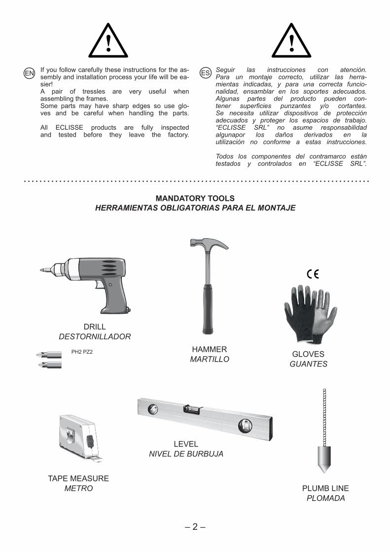
iEN If you follow carefully these instructions for the as-
sembly and installation process your life will be ea-sier!A pair of tressles are very useful whenassembling the frames.Some parts may have sharp edges so use glo-ves and be careful when handling the parts.
All ECLISSE products are fully inspected and tested before they leave the factory.
Seguir las instrucciones con atención.Para un montaje correcto, utilizar las herra-mientas indicadas, y para una correcta funcio-nalidad, ensamblar en los soportes adecuados.Algunas partes del producto pueden con-tener superficies punzantes y/o cortantes.Se necesita utilizar dispositivos de protección adecuados y proteger los espacios de trabajo.“ECLISSE SRL” no asume responsabilidad algunapor los daños derivados en la utilización no conforme a estas instrucciones.
Todos los componentes del contramarco están testados y controlados en “ECLISSE SRL”.
ES
– 2 –
MANDATORY TOOLSHERRAMIENTAS OBLIGATORIAS PARA EL MONTAJE
DRILLDESTORNILLADOR
GLOVESGUANTES
HAMMERMARTILLO
PH2 PZ2
PLUMB LINEPLOMADA
TAPE MEASUREMETRO
LEVELNIVEL DE BURBUJA
i
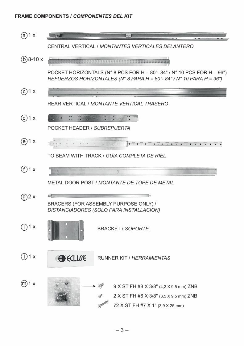
FRAME COMPONENTS / COMPONENTES DEL KIT
– 3 –
a 1 x
CENTRAL VERTICAL / MONTANTES VERTICALES DELANTERO
8-10 x
POCKET HORIZONTALS (N° 8 PCS FOR H = 80"- 84" / N° 10 PCS FOR H = 96")REFUERZOS HORIZONTALES (N° 8 PARA H = 80"- 84" / N° 10 PARA H = 96")
b
c 1 x
REAR VERTICAL / MONTANTE VERTICAL TRASERO
d 1 x
POCKET HEADER / SUBREPUERTA
e 1 x
TO BEAM WITH TRACK / GUIA COMPLETA DE RIEL
f 1 x
METAL DOOR POST / MONTANTE DE TOPE DE METAL
g 2 xBRACERS (FOR ASSEMBLY PURPOSE ONLY) / DISTANCIADORES (SOLO PARA INSTALLACION)
i 1 x BRACKET / SOPORTE
l 1 x RUNNER KIT / HERRAMIENTAS
9 X ST FH #8 X 3/8" (4,2 X 9,5 mm) ZNB
2 X ST FH #6 X 3/8" (3,5 X 9,5 mm) ZNB
72 X ST FH #7 X 1" (3,9 X 25 mm)
m 1 x
d
c
a
a
b
c
click
i
i
i
click
– 4 –
1 2
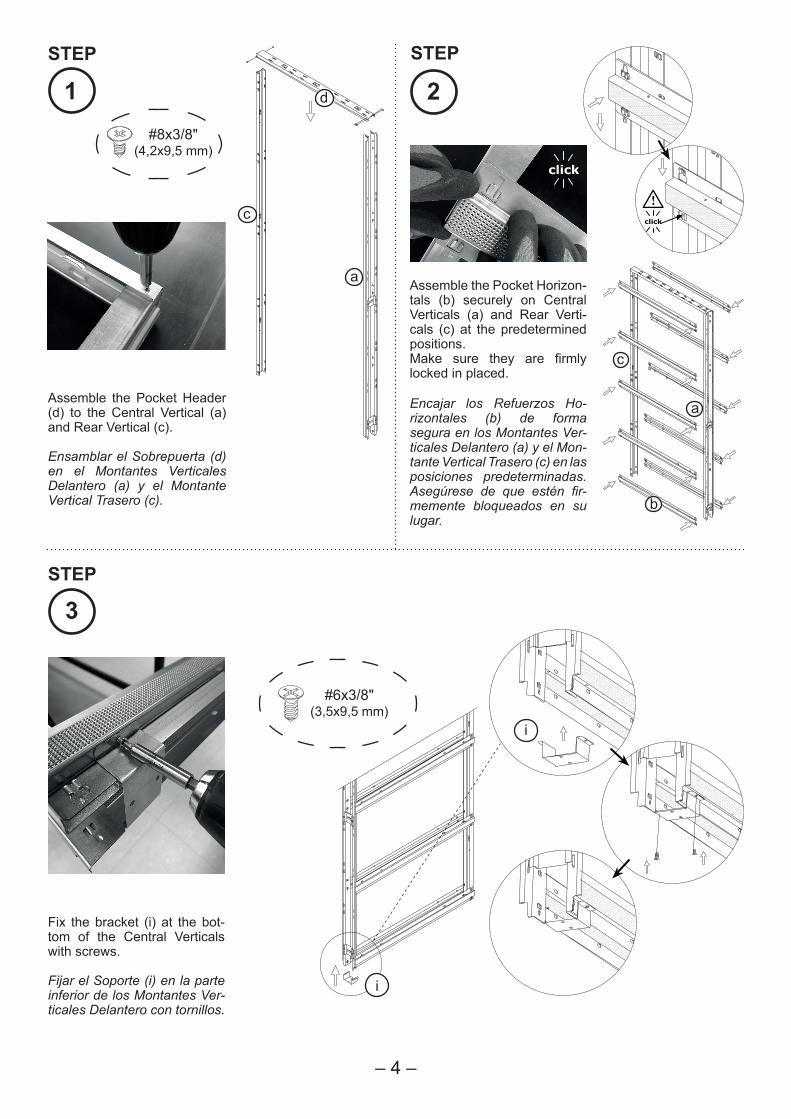
Assemble the Pocket Header (d) to the Central Vertical (a) and Rear Vertical (c).
Ensamblar el Sobrepuerta (d) en el Montantes Verticales Delantero (a) y el Montante Vertical Trasero (c).
#8x3/8"(4,2x9,5 mm)
Assemble the Pocket Horizon-tals (b) securely on Central Verticals (a) and Rear Verti-cals (c) at the predetermined positions.Make sure they are firmly locked in placed.
Encajar los Refuerzos Ho-rizontales (b) de forma segura en los Montantes Ver-ticales Delantero (a) y el Mon-tante Vertical Trasero (c) en las posiciones predeterminadas. Asegúrese de que estén fir-memente bloqueados en su lugar.
3
#6x3/8"(3,5x9,5 mm)
Fix the bracket (i) at the bot-tom of the Central Verticals with screws.
Fijar el Soporte (i) en la parte inferior de los Montantes Ver-ticales Delantero con tornillos.
STEP STEP
STEP
eclick
dclick
e
e
f
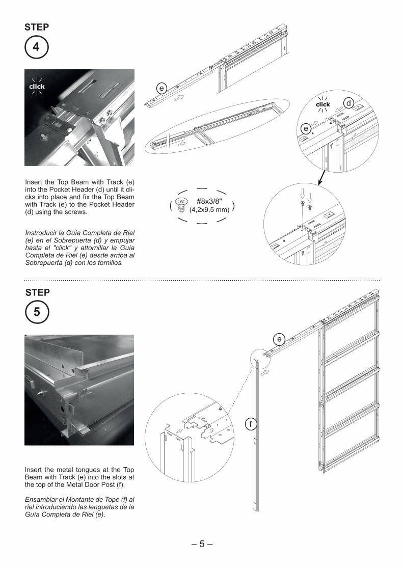
4
Insert the Top Beam with Track (e) into the Pocket Header (d) until it cli-cks into place and fix the Top Beam with Track (e) to the Pocket Header (d) using the screws.
#8x3/8"(4,2x9,5 mm)
Instroducir la Guìa Completa de Riel (e) en el Sobrepuerta (d) y empujar hasta el "click" y attornillar la Guìa Completa de Riel (e) desde arriba al Sobrepuerta (d) con los tornillos.
STEP
5
Insert the metal tongues at the Top Beam with Track (e) into the slots at the top of the Metal Door Post (f).
Ensamblar el Montante de Tope (f) al riel introduciendo las lenguetas de la Guía Completa de Riel (e).
STEP
– 5 –
e
f
g
g
g
– 6 –
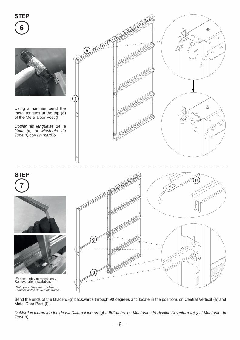
6
Using a hammer bend the metal tongues at the top (e) of the Metal Door Post (f).
Doblar las lenguetas de la Guìa (e) al Montante de Tope (f) con un martillo.
7
Bend the ends of the Bracers (g) backwards through 90 degrees and locate in the positions on Central Vertical (a) and Metal Door Post (f).
Doblar las extremidades de los Distanciadores (g) a 90° entre los Montantes Verticales Delantero (a) y el Montante de Tope (f).
* For assembly purposes only. Remove prior installation.* Solo para fines de montaje. Eliminar antes de la instalación.
STEP
STEP
Finished FloorLevel
Acabado al
Ras
del Suelo
Finished FloorLevel
Acabado al Ras del Suelo
ii
i
i
i
d
e
f
c
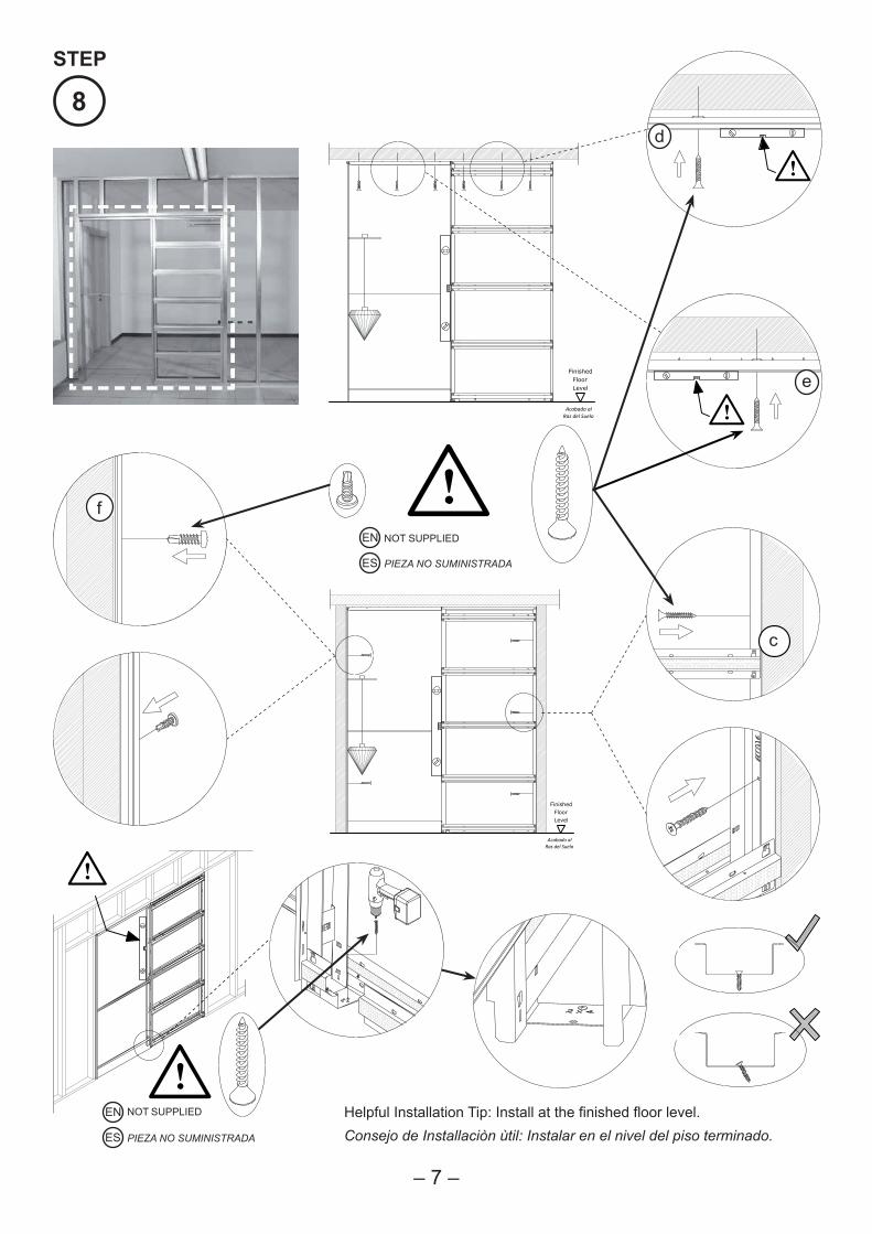
8
Helpful Installation Tip: Install at the finished floor level.Consejo de Installaciòn ùtil: Instalar en el nivel del piso terminado.
– 7 –
EN NOT SUPPLIED
PIEZA NO SUMINISTRADAES
EN NOT SUPPLIED
PIEZA NO SUMINISTRADAES
STEP
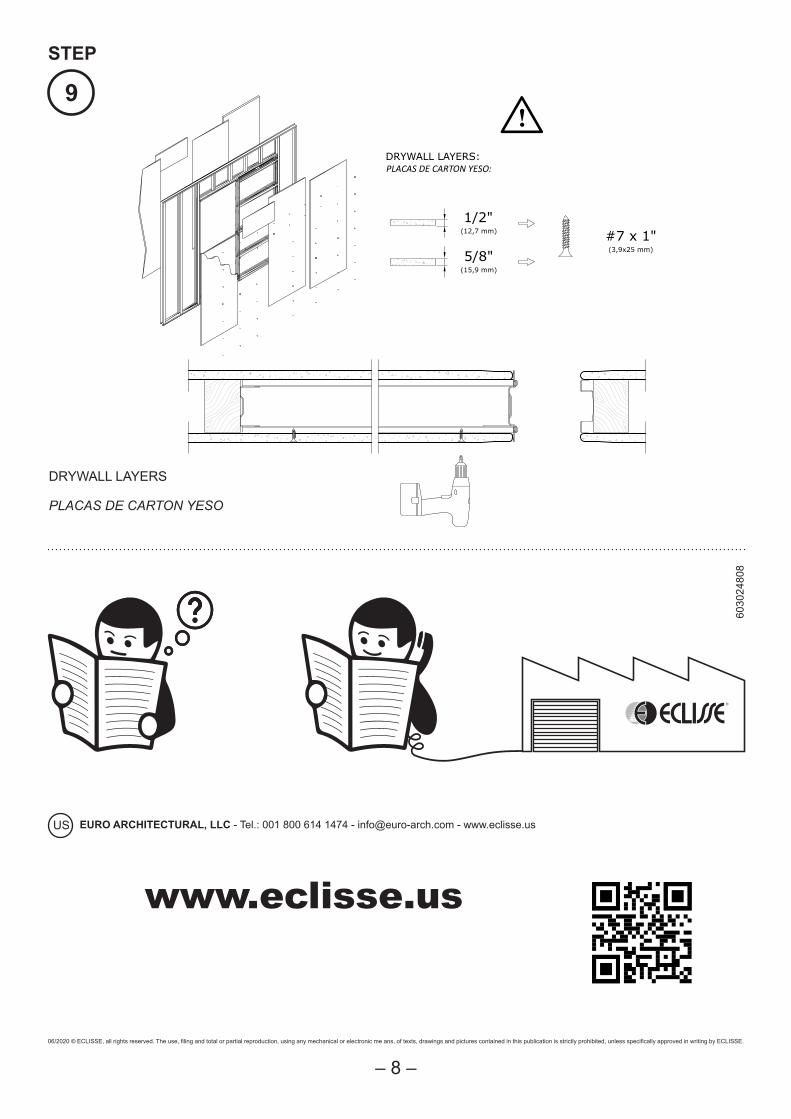
#7 x 1"(3,9x25 mm)
1/2"(12,7 mm)
5/8"(15,9 mm)
DRYWALL LAYERS:PLACAS DE CARTON YESO:
i9
DRYWALL LAYERS
PLACAS DE CARTON YESO
www.eclisse.us
EURO ARCHITECTURAL, LLC - Tel.: 001 800 614 1474 - [email protected] - www.eclisse.usUS
06/2020 © ECLISSE, all rights reserved. The use, filing and total or partial reproduction, using any mechanical or electronic me ans, of texts, drawings and pictures contained in this publication is strictly prohibited, unless specifically approved in writing by ECLISSE.
6030
2480
8
– 8 –
STEP