02454a precast concrete piling
TRANSCRIPT
**************************************************************************USACE / NAVFAC / AFCESA UFGS-02454A (February 1998) ----------------------------Preparing Activity: USACE Replacing without revision CEGS of same number and date
UNIFIED FACILITIES GUIDE SPECIFICATIONS
**************************************************************************
SECTION TABLE OF CONTENTS
DIVISION 02 - SITE CONSTRUCTION
SECTION 02454A
PRECAST CONCRETE PILING
02/98
PART 1 GENERAL
1.1 REFERENCES 1.2 MEASUREMENT AND PAYMENT 1.2.1 Lump Sum 1.2.1.1 Piling Quantities 1.2.1.2 Variations in Pile Quantities 1.2.1.3 Variations in the Number of Pile Load Tests 1.2.1.4 Variations in Test Pile Withdrawals 1.2.2 Unit Price 1.2.2.1 Piling 1.2.2.2 Load Test 1.2.2.3 Pile Withdrawals 1.3 SUBMITTALS 1.4 EXPERIENCE 1.5 STORAGE AND HANDLING 1.6 SUBSURFACE DATA
PART 2 PRODUCTS
2.1 PILES 2.1.1 Length 2.1.2 Ordering 2.1.3 Concrete 2.1.4 Reinforcing Steel 2.2 FABRICATION 2.2.1 Forms 2.2.2 Concrete Placement 2.2.3 Curing 2.2.4 Build-Up and Splicing 2.2.5 Chamfering
SECTION 02454A Page 1
PART 3 EXECUTION
3.1 INSTALLATION 3.1.1 Pile Hammers 3.1.2 Driving Helmets and Pile Cushions 3.1.3 Pile Driving 3.1.4 Splices 3.1.5 Tolerances in Driving 3.1.6 Cutting of Piles 3.1.7 Rejected Piles 3.1.8 Predrilling 3.1.9 Pile Heave 3.1.10 Long Piles 3.1.11 Jetting of Piles 3.2 FIELD TEST AND INSPECTIONS 3.2.1 Test Piles 3.2.2 Load Tests 3.2.3 Safe Design Capacity 3.2.4 Inspection 3.2.5 Pile Capacity 3.3 SPECIAL INSPECTION AND TESTING FOR SEISMIC-RESISTING SYSTEMS
-- End of Section Table of Contents --
SECTION 02454A Page 2
**************************************************************************USACE / NAVFAC / AFCESA UFGS-02454A (February 1998) ----------------------------Preparing Activity: USACE Replacing without revision CEGS of same number and date
UNIFIED FACILITIES GUIDE SPECIFICATIONS
**************************************************************************
SECTION 02454A
PRECAST CONCRETE PILING02/98
**************************************************************************NOTE: This guide specification covers the requirements for precast, reinforced concrete pilings.
Comments and suggestions on this guide specification are welcome and should be directed to the technical proponent of the specification. A listing of technical proponents, including their organization designation and telephone number, is on the Internet.
Recommended changes to a UFGS should be submitted as a Criteria Change Request (CCR).
Use of electronic communication is encouraged.**************************************************************************
PART 1 GENERAL
1.1 REFERENCES
**************************************************************************NOTE: Issue (date) of references included in project specifications need not be more current than provided by the latest change (Notice) to this guide specification.
**************************************************************************
The publications listed below form a part of this specification to the extent referenced. The publications are referred to in the text by basic designation only.
AMERICAN SOCIETY FOR TESTING AND MATERIALS (ASTM)
ASTM A 615/A 615M (1996a) Deformed and Plain Billet-Steel Bars for Concrete Reinforcement
SECTION 02454A Page 3
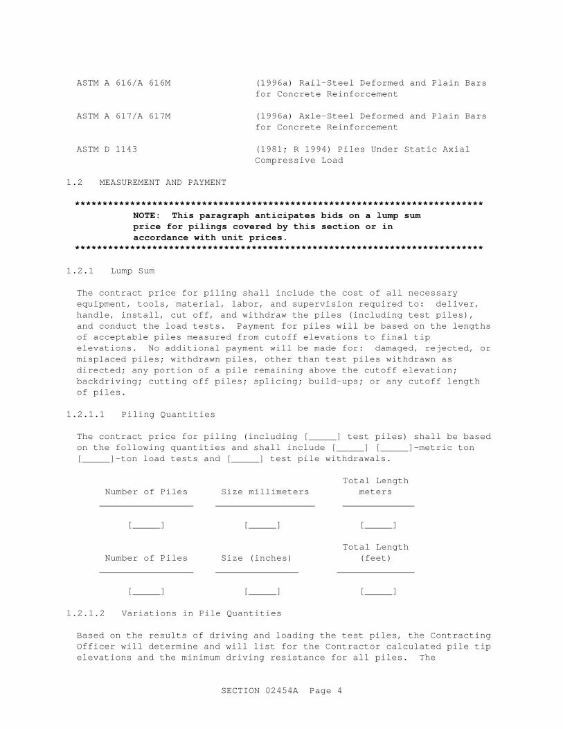
ASTM A 616/A 616M (1996a) Rail-Steel Deformed and Plain Bars for Concrete Reinforcement
ASTM A 617/A 617M (1996a) Axle-Steel Deformed and Plain Bars for Concrete Reinforcement
ASTM D 1143 (1981; R 1994) Piles Under Static Axial Compressive Load
1.2 MEASUREMENT AND PAYMENT
**************************************************************************NOTE: This paragraph anticipates bids on a lump sum price for pilings covered by this section or in accordance with unit prices.
**************************************************************************
1.2.1 Lump Sum
The contract price for piling shall include the cost of all necessary equipment, tools, material, labor, and supervision required to: deliver, handle, install, cut off, and withdraw the piles (including test piles), and conduct the load tests. Payment for piles will be based on the lengths of acceptable piles measured from cutoff elevations to final tip elevations. No additional payment will be made for: damaged, rejected, or misplaced piles; withdrawn piles, other than test piles withdrawn as directed; any portion of a pile remaining above the cutoff elevation; backdriving; cutting off piles; splicing; build-ups; or any cutoff length of piles.
1.2.1.1 Piling Quantities
The contract price for piling (including [_____] test piles) shall be based on the following quantities and shall include [_____] [_____]-metric ton [_____]-ton load tests and [_____] test pile withdrawals.
Total Length Number of Piles Size millimeters meters _________________ __________________ _____________
[_____] [_____] [_____]
Total Length Number of Piles Size (inches) (feet) _________________ _______________ ______________
[_____] [_____] [_____]
1.2.1.2 Variations in Pile Quantities
Based on the results of driving and loading the test piles, the Contracting Officer will determine and will list for the Contractor calculated pile tip elevations and the minimum driving resistance for all piles. The
SECTION 02454A Page 4

Contracting Officer reserves the right to increase or decrease the total length of piles to be furnished and installed by changing the pile locations or elevations, requiring the installation of additional piles, or directing the omission of piles from the requirements shown and specified. Should the length of piles installed vary from that specified because of added or omitted piles or variations in the pile lengths, the contract price for piling shall be adjusted by the applicable contract unit price per meter foot (by size) for "Additional Pile Length" or "Omitted Pile Length" multiplied by the actual length added or omitted.
1.2.1.3 Variations in the Number of Pile Load Tests
The Contracting Officer reserves the right to increase or decrease the number of pile load tests from that specified. For each load test added or deleted, the contract price shall be adjusted by the applicable contract unit price for "Each Additional Pile Load Test" or "Each Omitted Pile Load Test."
1.2.1.4 Variations in Test Pile Withdrawals
Should the number of test pile withdrawals be increased above the specified number at the direction of the Contracting Officer, the contract price for piling shall be adjusted by the contract unit price for "Each Additional Test Pile Withdrawn" multiplied by the number of additional test piles withdrawn.
1.2.2 Unit Price
**************************************************************************NOTE: Where the contract is based on unit price, paragraph Lump Sum should be deleted and the following paragraph used.
**************************************************************************
1.2.2.1 Piling
The Contractor will be paid at the contract unit price per meter foot (including test piles), for "Piling" multiplied by the total length in meters feet of acceptable piles actually installed. The Contracting Officer reserves the right to increase or decrease the total length of piles to be furnished and installed by changing the foundation pile locations or elevations, requiring the installation of additional piles, or requiring omission of piles. Payment shall constitute full compensation for furnishing, delivering, handling, and installing all material, labor, and equipment necessary to install the foundation piles. The Contractor will not be allowed payment for withdrawn, broken, or rejected piles or (except for test piles) for any portion of any pile remaining above the cutoff point.
1.2.2.2 Load Test
The contract includes [_____] [_____]-metric ton [_____]-ton pile load tests. The Contracting Officer reserves the right to increase or decrease the number of load tests. Adjustments in the contract price will be made
SECTION 02454A Page 5
for such increase or decrease by the contract price for "Additional Pile Load Test" or "Omitted Pile Load Test."
1.2.2.3 Pile Withdrawals
The Contractor will be paid at the contract unit price each for "Pile Withdrawals" multiplied by the number of piles withdrawn as directed. The Contracting Officer reserves the right to increase or decrease the number of pile withdrawals.
1.3 SUBMITTALS
**************************************************************************NOTE: Submittals must be limited to those necessary for adequate quality control. The importance of an item in the project should be one of the primary factors in determining if a submittal for the item should be required.
Indicate submittal classification in the blank space following the name of the item requiring the submittal by using "G" when the submittal requires Government approval. Submittals not classified as "G" will show on the submittal register as "Information Only". For submittals requiring Government approval on Army projects, a code of up to three characters within the submittal tags may be used following the "G" designation to indicate the approving authority. Codes for Army projects using the Resident Management System (RMS) are: "AE" for Architect-Engineer; "DO" for District Office (Engineering Division or other organization in the District Office); "AO" for Area Office; "RO" for Resident Office; and "PO" for Project Office.
**************************************************************************
Government approval is required for submittals with a "G" designation; submittals not having a "G" designation are for information only. When used, a designation following the "G" designation identifies the office that will review the submittal for the Government. The following shall be submitted in accordance with Section 01330 SUBMITTAL PROCEDURES:
SD-02 Shop Drawings
Installation; [_____], [_____]
Detail drawings to demonstrate compliance of driving equipment, including hammer and pile cushions, and to indicate methods of forming, reinforcing, splicing, and casting of piles.
Pile Driving; [_____], [_____].
A complete and accurate record of each driven pile. The record shall indicate the pile location (as driven), size, length, final
SECTION 02454A Page 6
elevation of tip and top, pile weight, number of splices and locations, blows required for each meter foot of penetration throughout the entire length of the pile and for the final 150 mm 6 inches of penetration, and the total driving time. The record also shall include the type and size of the hammer used, the rate of operation, and the type and dimensions of driving helmet and cushion block used. Any unusual conditions encountered during pile installation shall be recorded and immediately reported to the Contracting Officer.
SD-06 Test Reports
Field Test and Inspections; [_____], [_____]
A complete report on the pile test within [seven] [_____] days of completion of each pile test, including, but not limited to, a description of the pile driving equipment, driving records for both test piles and reaction piles, complete test data, analysis of test data, and recommended allowable design loads based on the pile test results. The report shall be prepared by or under the direct supervision of a registered professional engineer experienced in pile load testing and load test analysis.
1.4 EXPERIENCE
The work shall be performed by a Contractor specializing in the required foundation system and having experience installing the specified foundation system under similar subsurface conditions.
1.5 STORAGE AND HANDLING
Piles shall not be subject to overstress or any other condition that may cause damage to the piles during storing and/or handling.
1.6 SUBSURFACE DATA
Subsurface soil data logs are [shown on the drawings.] [appended to the SPECIAL CLAUSES.] The subsurface investigation report and samples of materials as taken from subsurface investigations may be examined at [_____].
PART 2 PRODUCTS
2.1 PILES
2.1.1 Length
From the results of test-pile driving and test-pile loading specified in paragraph FIELD TEST AND INSPECTIONS, the Contracting Officer will specify the necessary driving resistances and pile tip elevation at various locations of the work. [At least 305 mm 1 foot of overlength will be allowed for cutting at the required cutoff elevation] [Where piles longer than the designated effective lengths, measured from tip to cutoff elevation, are required to provide specified bearings capacities, the
SECTION 02454A Page 7

longer piles shall be provided] [Where the specified bearing capacities are obtained with piles of lengths less than the designated effective lengths, shorter piles may be used, subject to approval].
2.1.2 Ordering
Except piles for test purposes, any piles ordered or delivered to the work site prior to verification of the required lengths and establishment of criteria for driving permanent piles shall be at the risk of the Contractor.
2.1.3 Concrete
Concrete shall conform to Section 03300 CAST-IN-PLACE STRUCTURAL CONCRETE with minimum compressive strength of [_____] MPa psi at 28 days. The maximum size of coarse aggregate shall be [_____] mm inches. Slump shall be [_____] to [_____] mm inches for manual compaction and [_____] to [_____] mm inches when mechanical vibration is used.
2.1.4 Reinforcing Steel
Reinforcing steel shall be of the dimensions and sizes indicated and shall comply with [ASTM A 615/A 615M, Grade [40] [60]] [ASTM A 616/A 616M, Grade [50] [60]] [ASTM A 617/A 617M, Grade [40] [60]].
2.2 FABRICATION
Pre-cast concrete piles shall be produced by a manufacturer certified under the PCI Plant Certification Program.
2.2.1 Forms
Forms shall be wood, metal, or other approved material, built to provide piles that conform to the dimensions and shapes indicated. Forms shall be constructed sufficiently tight to prevent seepage of the mortar from the mix and shall be of sufficient strength to prevent distortion. Piles shall be independently cast. Forms shall be thoroughly cleaned and oiled with a nonstaining mineral oil before initial use and before each reuse. The use of any other form-release agent shall require prior approval. Forms shall be constructed accurately and set on unyielding bases.
2.2.2 Concrete Placement
Each unit shall be poured in one continuous operation, starting at one end of the pile and continuing to the other without interruption. Exposed surfaces shall be screeded to a uniform even surface and finished to match formed sides of the pile. Piles shall be cast so that the lifting points indicated are clearly marked and accessible for moving the piles as required. Each pile shall have the date of casting plainly indented in the concrete. Piles shall not be cast or piled in tiers except when and as directed. Piles shall be lifted and supported only at predesignated lifting points. Side forms shall remain in place for at least 48 hours after placement of concrete if regular portland cement is used or at least 24 hours if high-early-strength cement is used. The exposed or top face of piles shall be protected from the direct rays of the sun and from wind by
SECTION 02454A Page 8
wet-burlap covering, an approved impervious sheet material, or an approved membrane-forming curing compound; and the sides shall be likewise protected after forms are removed.
2.2.3 Curing
Concrete shall be cured as specified in Section 03300 CAST-IN-PLACE STRUCTURAL CONCRETE except as modified herein. All concrete shall be maintained above 10 degrees C 50 degrees F and in a moist condition for at least 7 days if made with regular portland cement or at least 3 days if made with high-early-strength cement after placing or until design strength is obtained. Where extreme conditions of hot weather or wind produce surface crazing or cracks, all exposed surfaces shall be fog-sprayed starting immediately after strike-off of the fresh concrete. In cold weather all precautions for placing concrete shall be as specified in Section 03300 CAST-IN-PLACE STRUCTURAL CONCRETE. Where piles are cured by steam or other approved methods, the curing time may be reduced provided the required compressive strength of the concrete is obtained. Piles may be removed from the forms when the concrete has attained sufficient strength to prevent deformation, subject to prior approval.
2.2.4 Build-Up and Splicing
[The Contractor will not be permitted to build up piles] [The Contractor will be permitted to lengthen piles by build-up [upon approval] [as indicated]] [Sectional precast piles will not be permitted] [The Contractor will be permitted to install sectional precast piles [with not more than [_____] splices per pile]] [Splices shall be of those types as indicated] [Proprietary prefabricated splices may be used with prior approval] [Driving of a pile after build-up or splicing shall not be resumed until approved] [Splices shall possess sufficient tensile strength to resist any tension due to uplift, pressures, heave, tensile waves in driving, or any other forces that might generate tension in the splice area].
2.2.5 Chamfering
The edges and corners of the pile shall be chamfered as shown.
PART 3 EXECUTION
3.1 INSTALLATION
3.1.1 Pile Hammers
The hammer used shall have a delivered energy suitable for the total weight of the pile, the character of subsurface material to be encountered, and the pile capacity to be developed. The driving energy of the hammer shall be not less than 20,337 N-m (15,000 foot-pounds). 15,000 foot-pounds. Diesel-powered hammers shall be operated at the rate recommended by the manufacturer throughout the entire driving period. Sufficient pressure shall be maintained at the steam hammer so that: (a) for a double-acting hammer, the number of blows per minute during and at the completion of driving of a pile is equal approximately to that at which the hammer is rated; (b) for a single-acting hammer, there is full upward stroke of the
SECTION 02454A Page 9

ram; and (c) for a differential type hammer, there is a slight rise of the hammer base during each upward stroke.
3.1.2 Driving Helmets and Pile Cushions
A driving helmet or cap, including a pile cushion, shall be used between the top of the pile and the ram to prevent impact damage to the pile. The driving helmet, or cap and pile cushion combination, shall be capable of protecting the head of the pile, minimizing energy absorption and dissipation, and transmitting hammer energy uniformly over the top of the pile. The driving helmet or cap shall fit loosely around the top of the pile so that the pile is not restrained by the driving cap if the pile tends to rotate during driving. The pile cushion may be of solid wood, of laminated construction using plywood, softwood, or hardwood boards, or of other approved cushioning material. The pile cushion shall completely cover the top surface of the pile and shall be retained by the driving helmet. The minimum thickness of the pile cushion shall be 75 mm (3 inches), 3 inches, and the thickness shall be increased to suit the size and length of pile, character of subsurface material encountered, hammer characteristics, and required driving resistance. The pile cushion shall be replaced at any time it becomes highly compressed, charred, burned, or becomes deteriorated in any manner during driving.
3.1.3 Pile Driving
Driving shall be done with fixed leads to hold the pile firmly in position, alignment, and in axial alignment with the hammer. Piles shall be driven continuously and without interruption to or below the "calculated" tip elevation to reach a driving resistance in accordance with the schedule that the Contracting Officer will prepare from the load test results. The pile hammer used for driving shall be the same type and operated at the same rate and in the same manner as that used for driving the test piles. If a pile fails to reach the "calculated" tip elevation or if a pile reaches the "calculated" tip elevation without reaching the required driving resistance, the Contractor shall notify the Contracting Officer and perform the corrective measures as directed. No pile shall be driven until the excavation or fill in the area that piles are to occupy has been completed to within 305 mm 1 foot of the grade indicated. Final grading shall be accomplished after the pile driving has been completed. Piles shall be carefully located to the lines and spacing indicated and shall be driven either to the plumb position or the batter indicated. The hammer shall be operated at its short stroke when the tip of the pile encounters soft material of little resistance either at the start of the driving or in passing into poor subsoil. The hammer should continue at its short stroke until sufficient resistance is built up to prevent damage due to tensile wave stresses. When driving is interrupted before final penetration is reached, the record of the penetration shall not be taken until after at least a 305 mm 12 inch penetration has been obtained on the resumption of driving.
3.1.4 Splices
Unless otherwise directed, field splices shall be constructed as indicated. Splices shall maintain the true alignment and position of the pile sections
SECTION 02454A Page 10
and shall develop the full strength of the pile in both bearing and bending. Proprietary prefabricated splicer sleeves may be used upon approval.
3.1.5 Tolerances in Driving
**************************************************************************NOTE: Foundation piles should not be more than 75 to 150 mm (3 to 6 inches) from their intended plan position.
**************************************************************************
Top of any pile at elevation of cutoff shall be within [_____] mm inches of the planar location indicated. Manipulation of piles to force them into position will not be permitted. Piles shall be checked for heave, and those found to have heaved shall be redriven to the required tip elevation. Piles damaged or driven outside the above tolerances shall be replaced, or additional piles driven at locations specified by the Contracting Officer at no expense to the Government.
3.1.6 Cutting of Piles
Piles shall be cut off at the elevations indicated by an approved method and the surplus material shall be removed from the job site.
3.1.7 Rejected Piles
Piles damaged, mislocated, or driven out of alignment beyond the maximum tolerance shall be withdrawn and replaced by new piles or shall be cut off and abandoned. Additional piles shall be driven as directed, and excess cut off from piles; unacceptable piles shall be removed from the site of work. All work in connection with withdrawing and removing from the site rejected piles shall be done without additional cost to the Government.
3.1.8 Predrilling
**************************************************************************NOTE: Predrilling is normally terminated at a depth equal to two thirds of the total length of the pile embedment.
**************************************************************************
Predrilling will be permitted only when approved. The hole shall be [_____] mm inches less in diameter than the diagonal dimension of the pile. Predrilled piles shall be seated by final driving to provide the required pile capacity.
3.1.9 Pile Heave
When large pile clusters or piles are driven with very close spacing, periodic elevations shall be taken on the tops of all piles to observe and determine pile heave. When such checking indicates that pile heave has occurred, and when pile driving progresses beyond effective pile heave range, all heaved piles shall be redriven to either the original resistance
SECTION 02454A Page 11

or the elevation, or both, as directed.
3.1.10 Long Piles
Piles having a slenderness ratio greater than [22] [_____] shall be handled and driven with special precautions to ensure against overstress or leaning from a plumb or true position. The slenderness ratio shall be the pile length divided by the least radius of gyration of the pile. When a high-resistance strata lying near the surface must be penetrated, spud piles may be used only when authorized by the Contracting Officer to minimize hard driving of long piles during the early stages of driving operations.
3.1.11 Jetting of Piles
**************************************************************************NOTE: Jetting generally should not be permitted:
a. For piles dependent on side friction in fine-grained soils (high clay or silt content) with low-permeability where considerable time is required for the soil to reconsolidate around the piles.
b. For piles subject to uplift or lateral forces.
c. For piles adjacent to existing structures.
d. For piles in closely spaced clusters unless the load capacity is confirmed by test.
**************************************************************************
[Jetting of piles will not be permitted] [Jetting shall be discontinued at a depth approximately 1.5 m 5 feet above the "calculated" tip elevation; the remaining penetration shall be achieved by driving. Before the driving of the final 1.5 m 5 feet is started, the pile shall be firmly seated in place by the application of a number of reduced-energy hammer blows].
3.2 FIELD TEST AND INSPECTIONS
3.2.1 Test Piles
Test piles shall be of the type and shall be driven in the manner specified herein. The Contracting Officer will use test pile and load test data to determine "calculated" pile tip elevations and the necessary driving resistance. Test piles that are located within the tolerances indicated and that provide a safe design capacity as determined by the results of a satisfactory load test may be used in the finished work. Test piles shall be driven [at the locations indicated] [in the vicinity of the soil boring test holes No. [_____]] [Jetting will be authorized only when pile testing clearly establishes the validity of its use]. Test piles shall be driven to the tip elevation specified or indicated. The specified number of test piles shall be withdrawn as indicated after reaching the "calculated" tip elevation for visual inspection of the pile.
SECTION 02454A Page 12
3.2.2 Load Tests
**************************************************************************NOTE: This paragraph anticipates bids on a lump sum price for piling covered by this section, or in accordance with unit prices.
**************************************************************************
Load tests at locations shown or directed shall be made on test piles placed to the tip elevation indicated except as otherwise directed. Loading, testing, and recording of data shall be under the direct supervision of a registered professional engineer. The analysis of the load test data shall be under the supervision of the registered professional engineer. The installation of piles shall not proceed in a new area with substantially different subsurface conditions until a satisfactory load test has been performed in that area and the results approved. A minimum of [_____] days after submission of the test pile data shall be allowed for approval. A minimum of 3 days shall elapse after driving the pile before the initiation of the pile testing, unless otherwise directed. Test loading shall conform to the apparatus and methods stated in ASTM D 1143, cyclic loading method. The load shall be applied to the pile or pile group by [hydraulic jacks acting against an anchored reaction frame] [hydraulic jacks acting against a weighted platform or box] [direct loading of a weighted platform] using a spherical bearing to transmit the load to the pile.
3.2.3 Safe Design Capacity
The safe design capacity of a test pile as determined from the results of load tests shall be the lesser of the two values computed according to the following:
a. One-half of that load which causes a net settlement after rebound of not more than 0.23 mm per metric ton 0.01 inch per ton of total test load.
b. One-half of the load that causes a gross settlement of not more than 25 mm, 1 inch, provided the load settlement curve shows no sign of failure.
3.2.4 Inspection
The Contracting Officer may require that certain test piles be withdrawn for test and inspection to determine the condition of the piles. When so required, such piles shall be redriven only when approved. Withdrawn piles not suitable for redriving shall be treated as rejected piles as specified in paragraph INSTALLATION.
3.2.5 Pile Capacity
**************************************************************************The capacity, as driven, of single piles not in clusters in the structure should be not less than determined by the following formulas, modified
SECTION 02454A Page 13
according to the data obtained by the load tests:**************************************************************************
For single-acting hammers: R = 166.7WH/(S + 2.54 P/W) R = 2WH/(S + 0.1 P/W)
And double-acting hammers: R = 166.7E/(S + 2.54 P/W) R = 2E/(S + 0.1 P/W)
Where: R is the allowable static pile load in N. pounds.
W is the weight of the striking part of the hammer in N. pounds.
H is the effective height of fall in meters. feet.
E is the actual energy delivered by the hammer per blow in N-m. foot-pounds.
S is the average net penetration in mm inches per blow for the last five blows after the pile has been driven to a depth where successive blows produce approximately equal net penetration (a minimum distance of 1 meter 3 feet for friction piles).
P is the weight of the pile in N. pounds. (If P is less than W, P/W shall be taken as unity.)
3.3 SPECIAL INSPECTION AND TESTING FOR SEISMIC-RESISTING SYSTEMS
**************************************************************************NOTE: Include this paragraph only when special inspection and testing for seismic-resisting systems is required by paragraph 3.2 of FEMA 302, NEHRP RECOMMENDED PROVISIONS FOR SEISMIC REGULATIONS FOR NEW BUILDINGS AND OTHER STRUCTURES.
This paragraph will be applicable to both new buildings designed according to TI 809-04, SEISMIC DESIGN FOR BUILDINGS, and to existing building seismic rehabilitation designs done according to TI 809-05, SEISMIC EVALUATION AND REHABILITATION FOR BUILDINGS.
The designer must indicate on the drawings all locations and all features for which special inspection and testing is required in accordance with Chapter 3 of FEMA 302. This includes indicating the locations of all structural components and connections requiring inspection.
Add any additional requirements as necessary.**************************************************************************
Special inspections and testing for seismic-resisting systems and components shall be done in accordance with Section 01452 SPECIAL INSPECTION FOR SEISMIC-RESISTING SYSTEMS.
-- End of Section --
SECTION 02454A Page 14

SECTION 02454A Page 15