01 techrotation2 water
TRANSCRIPT

1
CE467: Senior Design II
Shikha RahmanCalPoly at SLOSpring 2013
Learning Objectives State Culvert design criteria.
Design Culverts.
Analyze existing culvert performances.
Use Nomographs for culvert design &analysis.
Culverts on StreetsCulverts in Detention Ponds

2
Culverts A culvert is a short conduit that conveys stormwater
under an embankment. Culverts typically used in roadway crossings and
detention pond outlets.
Culverts Allowable upstream water depth (headwater – HW)
Downstream water surface elevation (tailwater – TW)
Slope
Length.HW Depth
TW Depth
Culverts
Outlet
Entrance geometry. This includesheadwalls, wingwalls, alignment and culvertedge configuration.
Culverts Culvert material. Culvert material usually are
concrete and Corrugated Metal Pipe (CMP).
3
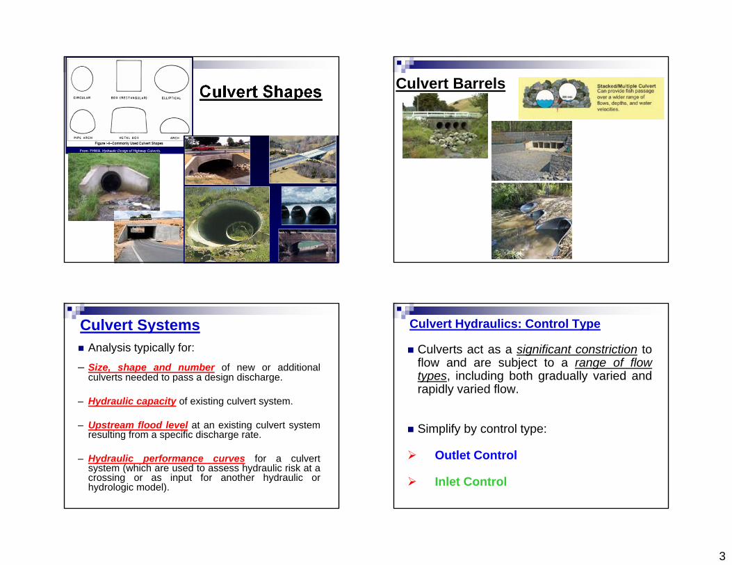
Culvert Shapes Culvert Barrels
Culvert Systems Analysis typically for:
– Size, shape and number of new or additionalculverts needed to pass a design discharge.
– Hydraulic capacity of existing culvert system.
– Upstream flood level at an existing culvert systemresulting from a specific discharge rate.
– Hydraulic performance curves for a culvertsystem (which are used to assess hydraulic risk at acrossing or as input for another hydraulic orhydrologic model).
Culvert Hydraulics: Control Type
Culverts act as a significant constriction toflow and are subject to a range of flowtypes, including both gradually varied andrapidly varied flow.
Simplify by control type:
Outlet Control
Inlet Control
4
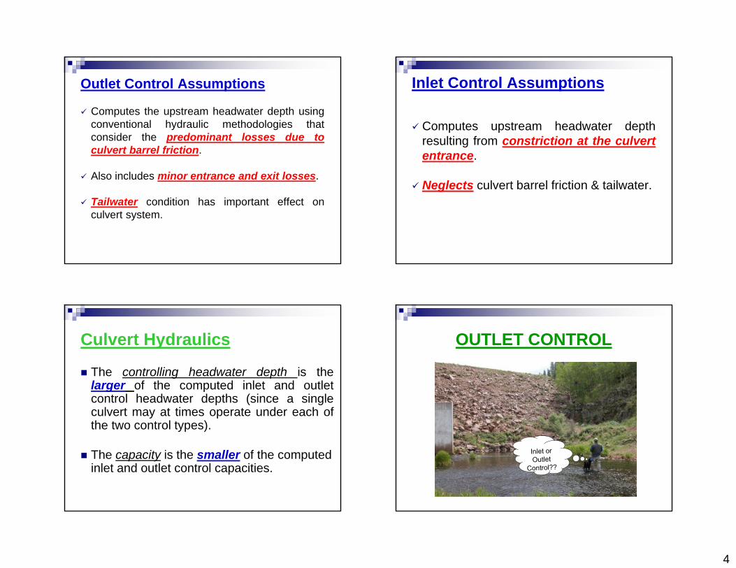
Outlet Control Assumptions
Computes the upstream headwater depth usingconventional hydraulic methodologies thatconsider the predominant losses due toculvert barrel friction.
Also includes minor entrance and exit losses.
Tailwater condition has important effect onculvert system.
Inlet Control Assumptions
Computes upstream headwater depthresulting from constriction at the culvertentrance.
Neglects culvert barrel friction & tailwater.
Culvert Hydraulics
The controlling headwater depth is thelarger of the computed inlet and outletcontrol headwater depths (since a singleculvert may at times operate under each ofthe two control types).
The capacity is the smaller of the computed inlet and outlet control capacities.
OUTLET CONTROL

1
Culvert Hydraulics: Outlet Control
Outlet Submerged
TWD≥ Culvert D
Outlet Unsubmerged
TWD< Culvert D
Culvert Hydraulics: Outlet Control

2
Culvert Hydraulics: Outlet Control
under outlet control
Culvert Hydraulics: Outlet Control
Four standard inlet types(schematic) (from Normann etal. (1985)).

3
Culvert Inlets at Entrance
Culvert Hydraulics: Outlet Control

Culvert Hydraulics: Outlet Control

Culvert Hydraulics: Outlet Control

1
Friction Losses in Barrel Calculated using Manning’s Equation.
unitSI 1.0
unit US94.1
3/42
22
2/13/22/13/2
Cm
RC
LnVh
L
hR
n
CSR
n
CV
ml
lmm
Outlet Control: Exit Losses
2
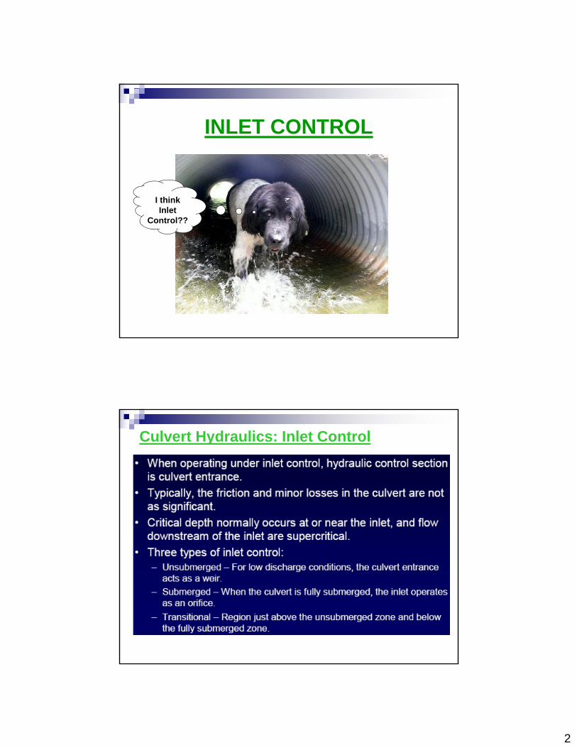
INLET CONTROL
I think Inlet
Control??
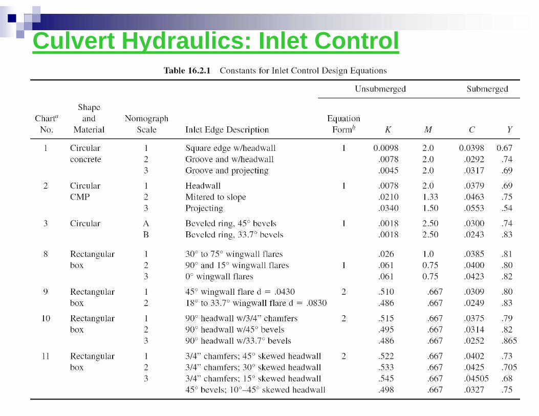
Culvert Hydraulics: Inlet Control

3
Culvert Hydraulics: Inlet Control
Types of inlet control.
(a) Outlet & inlet unsubmerged;
(b) Outlet submerged, inlet unsubmerged;
(c) Inlet submerged;
(d) Outlet & inlet submerged (from Normann et al. (1985)).
Inlet Unsubmerged
HWD<Culvert D
Inlet Submerged
HWD>Culvert D
Culvert Hydraulics: Inlet Control
Culvert Hydraulics: Inlet Control

Culvert Hydraulics: Inlet Control

Culvert Hydraulics: Inlet Control

2.0

English is the US unit
Not power of S, refers to notes


1
The maximum velocity allowed is 10 ft/s.

2
Nomographs: Inlet Control


1
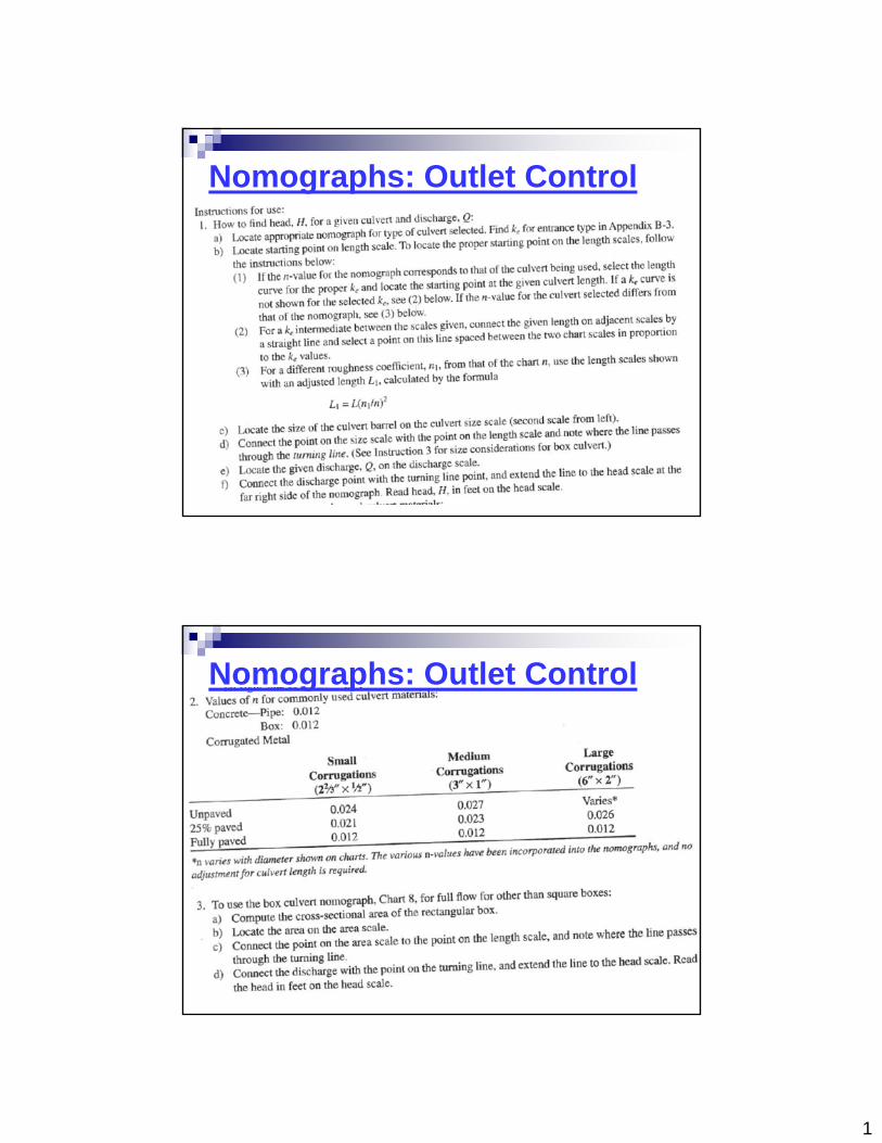
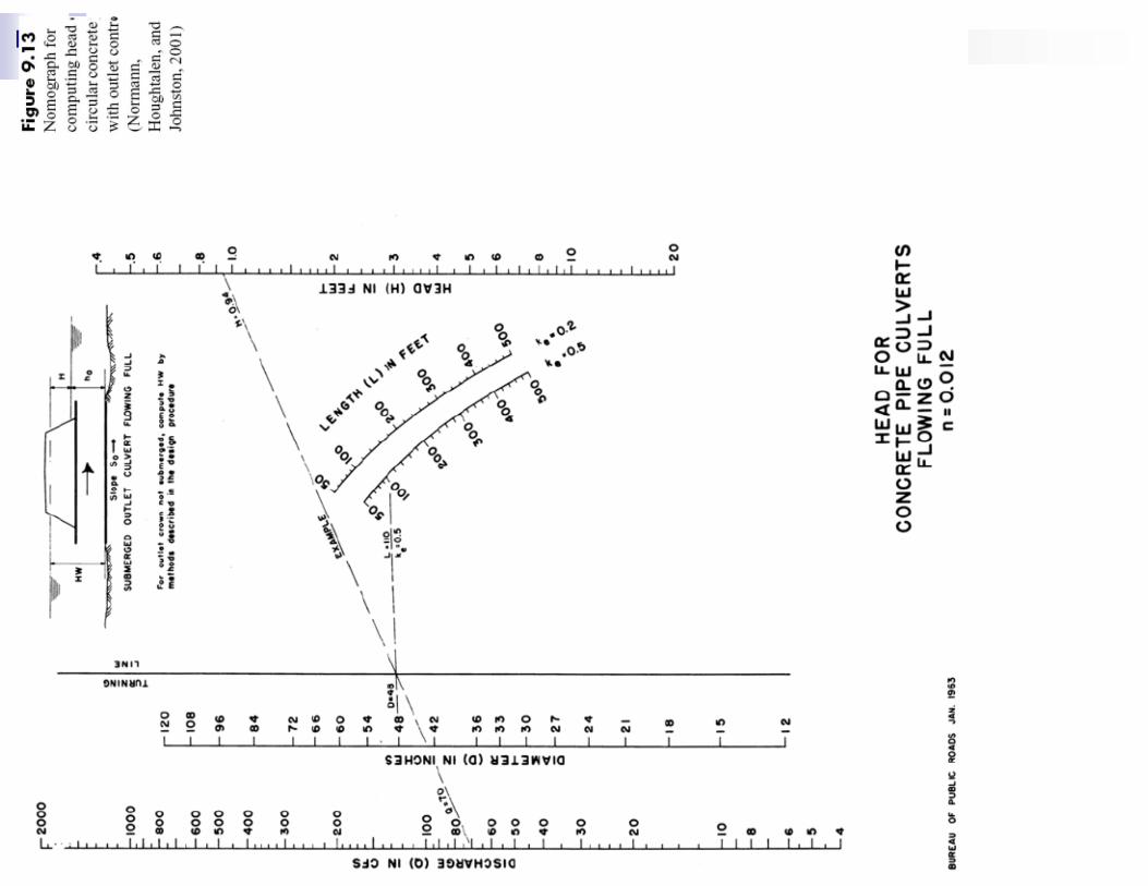
Nomographs: Outlet Control
Nomographs: Outlet Control


1
Example #3:A circular concrete pipe culvert has a diameter of 36 in., a length of 100 ft, anda slope of 0.50 percent, as illustrated in Figure below. The invert of the culvertwill match the channel bottom elevation, which is 125.30 ft at the upstream end.
Assuming that the culvert operates under inlet control, use nomograph(attached) to estimate the headwater elevations corresponding to discharges of30 and 60 cfs. The culvert inlet consists of a headwall with a square edge at thebarrel entrance.
1
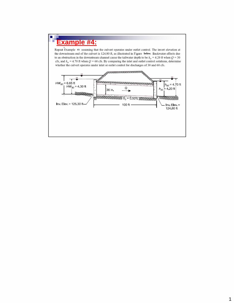
Example #4:#3
below.
