007565, 008667 & 009965 5hfrpphqghg,qvwdoodwlrq
TRANSCRIPT
1. Locate the most visible location to install control panel. 2. Securely (not permanently) mount control panel to wall. 3. Remove eyelet connector from end of chain and save. 4. Determine tank depth in inches. 5. Stand float on end on a flat work surface alongside a measuring tape and pull chain taut to desired
measurement. 6. Subtract 2" (50.8 mm) from determined measurement and mark chain. 7. Cut chain on mark then feed chain through bottom center hole in shaft and back out of either hole on
sides of shaft. 8. Secure chain with eyelet by crimping eyelet closed. 9. Loosen thumbscrews on sensor.10. Slide sensor, positioning arrow just inside top of clear window.11. Connect an ohmmeter to sensor leads.12. Using chain, pull orange indicator to bottom of gauge and confirm circuit is closed.13. Slowly release chain tension allowing spring to raise orange indicator to its full extension.14. Confirm circuit is now open.15. Tighten thumbscrews firmly, approximately 1 to 2 turns past hand tight - do no overtighten.16. Apply appropriate sealant (not Teflon® tape) to male threads of bung adaptor.17. Slowly lower weighted float into tank and tighten gauge, approximately 1 to 2 turns past hand tight. Do
not overtighten.18. Confirm orange indicator is at proper level - it tank is empty it should not be visible. (If visible, remove
sight glass and depress orange indicator. Reinstall sight glass. If orange indicator is still visible, recheck measurements (steps 4 - 6) and shorten chain as required.)
19. Solder (or wire nut) sensor leads then tape the connections.20. Seal hole with silicone or appropriate sealant.21. Connect wire to printed circuit board terminals marked "N/C SENSOR IN". Select a non-switched
24-hour hot 115v outlet, preferably dedicated solely for use with the 007.22. Connect transformer wires to printed circuit board terminal marked "12VDC POWER IN" .23. Secure transformer to outlet using outlet plate screw.24. Test control panel to confirm audible siren sounds and strobe light flashes.
DO NOT PLUG IN THE TRANSFORMER PRIOR TO CONNECTING WIRES TO CONTROL PANEL. ONLY USE BJE® BRAND TRANSFORMER WITH 007 TANK MONITORS.
TESTING / MAINTENANCE / INSPECTION
007
TAN
K
WARNING Never use with gasoline or highly flammable liquids.
Husky Corporation • 2325 Husky Way • Pacific, MO 63069 • Phone: (800) 325-3558 • Fax: (636) 825-7300 • www.husky.com Page 1 009312-8 12/2020
INSTALLATION INSTRUCTIONS
Daily• Confirm the AC power indicator is lit.• Confirm Siren toggle switch is in the "ON"
position.• Confirm audible siren sounds.• Confirm strobe light flashes.
Monthly• Remove sensor from tank and manually
raise / lower float to verify system goes into alarm mode.
• Manually test all accessories for proper function.
• Confirm all wires are properly connected to control panel and accessories.
• Follow all city, state, or federal wiring code requirements as appropriate.
• Apply city, state, or federal testing regulations as appropriate.
ANY TEST / INSPECTION FAILURE REQUIRES IMMEDIATE EQUIPMENT REPLACEMENT OR
REMOVAL FROM SERVICE.
MADE IN THE USA
007 Tank Monitor with Overfill Guard Tank Gauge
007565, 008667 & 009965Recommended Installation, Maintenance
and Inspection Instructions
Important safety instructions - save these instructions in a readily accessible location.WARNING: Cancer and Reproductive Harm - www.p65warnings.ca.gov

CAUTION: DO NOT EXCEED THE MAXIMUM MILLIAMP LOAD!Designed to drive up to 1000 milliamps of optional accessories.
ALWAYS ADHERE TO INSTALLATION / USAGE INSTRUCTIONS AND WARNINGS. Improper use may result in injury, damage, or hazardous spill.
Husky Corporation will, at its option, repair, replace, or credit the purchase price of any BJE® product deemed to be defective in material and/or workmanship for a period of one (1) year.
Buyer must return the products to Husky®, transportation charges prepaid. The warranty excludes damages due to malfunction, failure to follow manufacturer's installation, operation or maintenance instructions and guidelines, unauthorized modifications or alterations, abuse, or misuse.
The warranty provisions contained herein apply only to original purchasers who use the equipment for commercial or industrial purposes. There are not other warranties of merchantability, fitness for a particular purpose, or otherwise, and any other such warranties are hereby specifically disclaimed.
Husky assumes no liability for labor charges or other costs incurred by Buyer incidental to the service, adjustment, repair, return, removal or replacement of products. Husky is not responsible for any losses (including loss of profits or revenues) incurred by the purchaser during the time necessary to repair the equipment. Husky assumes no liability for any incidental, consequential, or other damages under any warranty, express or implied, and all such liability is hereby expressly excluded.
Husky reserves the right to change or improve the design of any Husky Oil Filter Crushers, Tank Monitors, Tank Gauges, Overfill Alarms, Overfill Accessories, Air Shut-off Valves, Solenoid Valves, and Electronic Drain Valves without assuming any obligations to modify any Husky Oil Filter Crushers, Tank Monitors, Tank Gauges, Overfill Alarms, Overfill Accessories, Air Shut-off Valves, Solenoid Valves, and Electronic Drain Valves previously manufactured.
WARRANTY
Husky Corporation • 2325 Husky Way • Pacific, MO 63069 • Phone: (800) 325-3558 • Fax: (636) 825-7300 • www.husky.com Page 2 009312-8 12/2020
• Use of equipment is at individuals’ own risk.
• Always abide and adhere to city, state, and federal regulations regarding use and installation of monitoring equipment.
• Always follow the product manufacturer’s installation and maintenance instructions.
• Always turn off all power to monitor during maintenance activities.
• Always replace or remove from service damaged equipment immediately.
• Always report leaks / spills / accidents to appropriate authorities.
• Always wear appropriate safety equipment during maintenance and inspection activities.
• Always have appropriate fire extinguishing equipment within 5 ft / 1.5 m of tanks.
• Always use Teflon® tape or appropriate thread sealant.
• The tank contents are the sole responsibility of the tank owner.
• Never allow waste product to touch eyes or skin.
• Never install monitors outdoors without proper protection from the elements.
• Never use on below ground storage tanks.
• Never exceed the maximum milliamps specified in manufacturer's installation and maintenance instructions.
• Never solely rely on this product; there is no substitute for human supervision.
• Never to be used as a component of any automatically controlled pump transfer system.
GENERAL WARNINGS / INSTRUCTIONS PERTAINING TO A RISK OF FIRE, ELECTRIC SHOCK OR INJURY TO PERSONS:
Important safety instructions - save these instructions in a readily accessible location.
Audible alarm won't shut off... 1. Replace control panel.
System won't go into alarm mode... 1. Verify all wires are connected properly. 2. Confirm transformer is plugged in. Audible alarm won't sound... 1. Confirm toggle switch is in "ON" position. Strobe light won't stop flashing... 1. Replace control panel.
Bulk Product Sensor activates alarm prematurely... 1. Confirm float is in the correct position. 2. Confirm pipe is not over 10 ft / 3 m long.
Applications Single or double walled above ground tanks.Fluids Test and warranty for oil, waste oil, diesel fuel, antifreeze, water and other fluids with a low
flash pointMilliamp load 750 mA maximum / 1000 mA maximum of optional accessoriesPipe ½" x 6" (12.7 mm x 152.4 mm) NPT PVCSensor BunaShipping Weight 8 lbs / 3.6 kgThread 2" / 50.8 mm NPTCase Quantity 5
TROUBLESHOOTING GUIDE
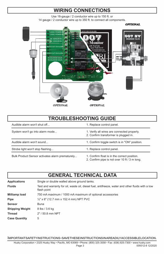
WIRING CONNECTIONS
GENERAL TECHNICAL DATA
Husky Corporation • 2325 Husky Way • Pacific, MO 63069 • Phone: (800) 325-3558 • Fax: (636) 825-7300 • www.husky.com Page 3 009312-8 12/2020
12VDC POWER IN12VDC POWER IN
NC SENSOR INNC SENSOR IN
-MUTED OUT ON ALARM
+-
POWER OUT ON ALARM+
TO SOLENOID VALVETO SOLENOID VALVE
Use 18-gauge / 2 conductor wire up to 150 ft. or 14 gauge / 2 conductor wire up to 350 ft. to connect all components.
Important safety instructions - save these instructions in a readily accessible location.
Husky Corporation • 2325 Husky Way • Pacific, MO 63069 • Phone: (800) 325-3558 • Fax: (636) 825-7300 • www.husky.com Page 4 009312-8 12/2020
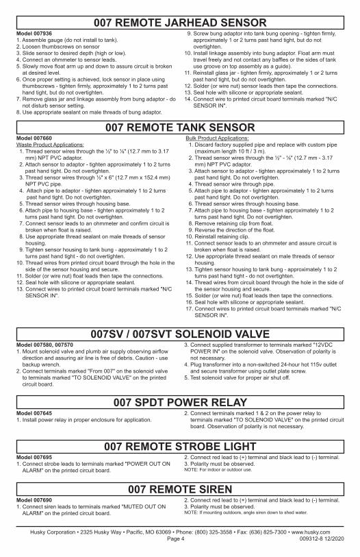
007 SPDT POWER RELAY
007 REMOTE STROBE LIGHT
007 REMOTE SIREN
Model 0076451. Install power relay in proper enclosure for application.
2. Connect terminals marked 1 & 2 on the power relay to terminals marked "TO SOLENOID VALVE" on the printed circuit board. Observation of polarity is not necessary.
Model 0076951. Connect strobe leads to terminals marked "POWER OUT ON
ALARM" on the printed circuit board.
2. Connect red lead to (+) terminal and black lead to (-) terminal.3. Polarity must be observed.NOTE: For indoor or outdoor use.
Model 0076901. Connect siren leads to terminals marked "MUTED OUT ON
ALARM" on the printed circuit board.
2. Connect red lead to (+) terminal and black lead to (-) terminal.3. Polarity must be observed.NOTE: If mounting outdoors, angle siren down to shed water.
007SV / 007SVT SOLENOID VALVE
007 REMOTE TANK SENSOR
Model 007580, 0075701. Mount solenoid valve and plumb air supply observing airflow
direction and assuring air line is free of debris. Caution - use backup wrench.
2. Connect terminals marked "From 007" on the solenoid valve to terminals marked "TO SOLENOID VALVE" on the printed circuit board.
3. Connect supplied transformer to terminals marked "12VDC POWER IN" on the solenoid valve. Observation of polarity is not necessary.
4. Plug transformer into a non-switched 24-hour hot 115v outlet and secure transformer using outlet plate screw.
5. Test solenoid valve for proper air shut off.
007 REMOTE JARHEAD SENSORModel 0079361. Assemble gauge (do not install to tank).2. Loosen thumbscrews on sensor3. Slide sensor to desired depth (high or low).4. Connect an ohmmeter to sensor leads.5. Slowly move float arm up and down to assure circuit is broken
at desired level.6. Once proper setting is achieved, lock sensor in place using
thumbscrews - tighten firmly, approximately 1 to 2 turns past hand tight, but do not overtighten.
7. Remove glass jar and linkage assembly from bung adaptor - do not disturb sensor setting.
8. Use appropriate sealant on male threads of bung adaptor.
9. Screw bung adaptor into tank bung opening - tighten firmly, approximately 1 or 2 turns past hand tight, but do not overtighten.
10. Install linkage assembly into bung adaptor. Float arm must travel freely and not contact any baffles or the sides of tank use groove on top assembly as a guide).
11. Reinstall glass jar - tighten firmly, approximately 1 or 2 turns past hand tight, but do not overtighten.
12. Solder (or wire nut) sensor leads then tape the connections.13. Seal hole with silicone or appropriate sealant.14. Connect wire to printed circuit board terminals marked "N/C
SENSOR IN".
Model 007660Waste Product Applications: 1. Thread sensor wires through the ½" to ⅛" (12.7 mm to 3.17
mm) NPT PVC adaptor. 2. Attach sensor to adaptor - tighten approximately 1 to 2 turns
past hand tight. Do not overtighten. 3. Thread sensor wires through ½" x 6" (12.7 mm x 152.4 mm)
NPT PVC pipe. 4. Attach pipe to adaptor - tighten approximately 1 to 2 turns
past hand tight. Do not overtighten. 5. Thread sensor wires through housing base. 6. Attach pipe to housing base - tighten approximately 1 to 2
turns past hand tight. Do not overtighten. 7. Connect sensor leads to an ohmmeter and confirm circuit is
broken when float is raised. 8. Use appropriate thread sealant on male threads of sensor
housing. 9. Tighten sensor housing to tank bung - approximately 1 to 2
turns past hand tight - do not overtighten.10. Thread wires from printed circuit board through the hole in the
side of the sensor housing and secure.11. Solder (or wire nut) float leads then tape the connections.12. Seal hole with silicone or appropriate sealant.13. Connect wires to printed circuit board terminals marked "N/C
SENSOR IN".
Bulk Product Applications: 1. Discard factory supplied pipe and replace with custom pipe
(maximum length 10 ft / 3 m). 2. Thread sensor wires through the ½" - ⅛" (12.7 mm - 3.17
mm) NPT PVC adaptor. 3. Attach sensor to adaptor - tighten approximately 1 to 2 turns
past hand tight. Do not overtighten. 4. Thread sensor wire through pipe. 5. Attach pipe to adaptor - tighten approximately 1 to 2 turns
past hand tight. Do not overtighten. 6. Thread sensor wires through housing base. 7. Attach pipe to housing base - tighten approximately 1 to 2
turns past hand tight. Do not overtighten. 8. Remove retaining clip from float. 9. Reverse the direction of the float.10. Reinstall retaining clip.11. Connect sensor leads to an ohmmeter and assure circuit is
broken when float is raised.12. Use appropriate thread sealant on male threads of sensor
housing.13. Tighten sensor housing to tank bung - approximately 1 to 2
turns past hand tight - do not overtighten.14. Thread wires from circuit board through the hole in the side of
the sensor housing and secure.15. Solder (or wire nut) float leads then tape the connections.16. Seal hole with silicone or appropriate sealant.17. Connect wires to printed circuit board terminals marked "N/C
SENSOR IN".