0 gauge - jimmcgeown.com
TRANSCRIPT

They were configured to individual railways requirements.
These 153hp, 0-4-0’s, built in considerable numbers, were ideal for working the restricted sidings & tight curves of factories, gasworks & dock sides. A number of these locos remain in operation today on preserved railways & heritage sites.
Jim McGeown, Connoisseur Models, 1 Newton Cottages, Nr Weobley, Herefordshire, HR4 8QX, Telephone 01544 318263
- 0 Gauge - Drewry 153hp Diesel Mechanical Shunter
Parts Identification & Chassis Assembly Instructions
Parts Required To Complete Slater’s Drewry Shunter Wheel Pack (Slater’s Catalogue Number 7839id) This pack contains 4 X wheels, 3 X axles, 6 X crankpins, all that’s required. Plunger Pickups if desired (Slater’s Catalogue Number 7157) Available From Slater’s Plastikard, Old Road, Darley Dale, Matlock, Derbyshire, DE4 2ER, Telephone 01629 734053. 1833 Motor and 40/1 Gear set, available from Connoisseur Models.
SKILL
BUILDER KIT
This Skill Builder Kit is intended to aid the newcomer to 0 gauge diesel era modelling to enjoy the construction of a sophisticated etched kit. Which once completed will have a level of finish & detail that will enable it to sit alongside their existing collection of the excellent factory produced locomotives from Heljan, Dapol & Minerva.
This is achieved through the physical parts design & photo instructions illustrating the step by step assembly of parts & the tools & techniques used. Assisting the modeller to build up their skills & confidence to tackle a wide variety of future etched metal kit building projects. Looking for a starter, diesel, loco kit? Then this is it!
Prototype The Drewry Car Co supplied bespoke Diesel Mechanical Shunting Locos to operators throughout Britain & across the world.
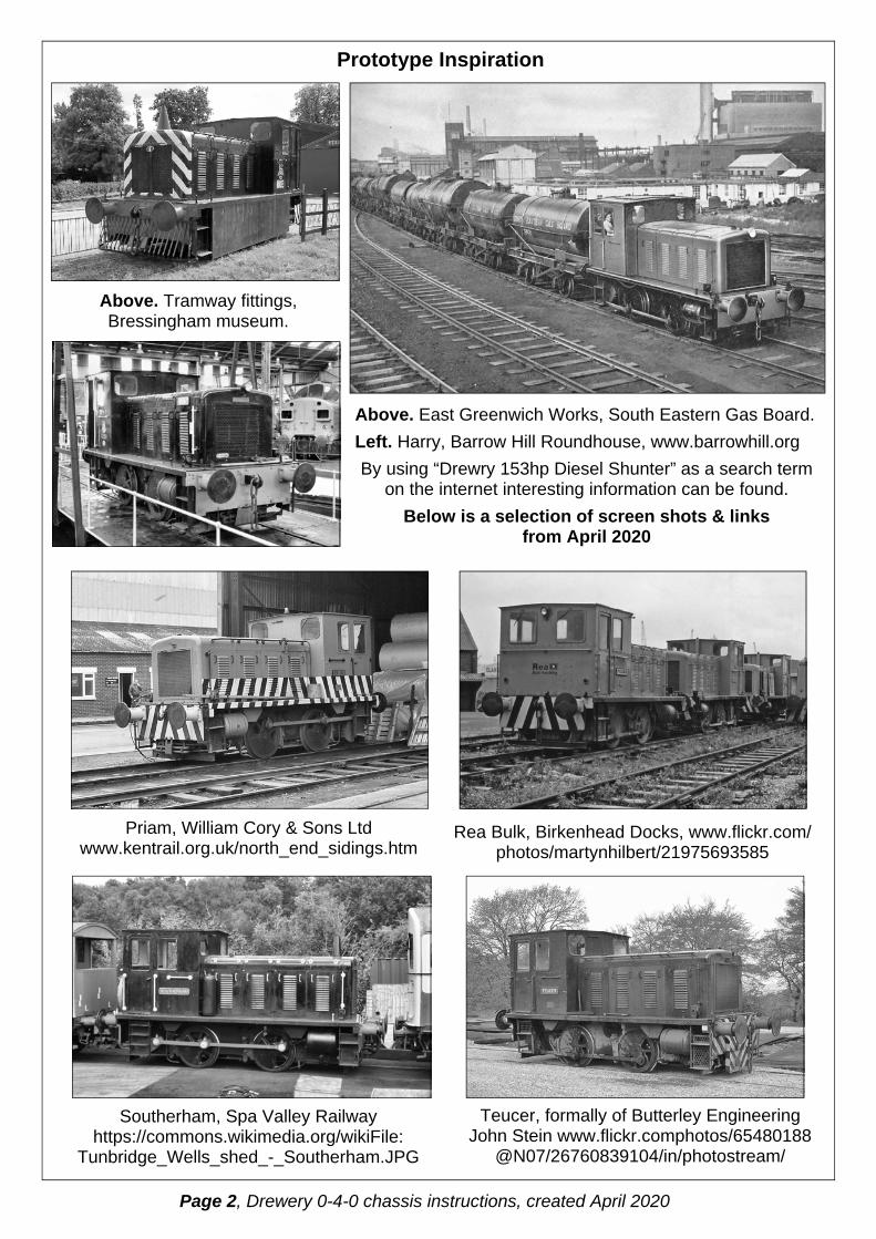
Priam, William Cory & Sons Ltd www.kentrail.org.uk/north_end_sidings.htm
Prototype Inspiration
Above. East Greenwich Works, South Eastern Gas Board.
Left. Harry, Barrow Hill Roundhouse, www.barrowhill.org
By using “Drewry 153hp Diesel Shunter” as a search term on the internet interesting information can be found.
Below is a selection of screen shots & links from April 2020
Above. Tramway fittings, Bressingham museum.
Rea Bulk, Birkenhead Docks, www.flickr.com/photos/martynhilbert/21975693585
Southerham, Spa Valley Railway https://commons.wikimedia.org/wikiFile:
Tunbridge_Wells_shed_-_Southerham.JPG
Teucer, formally of Butterley Engineering John Stein www.flickr.comphotos/65480188
@N07/26760839104/in/photostream/
Page 2, Drewery 0-4-0 chassis instructions, created April 2020

Brake mounting brackets X 4
Alternative cast brake gear X 4
L/H & R/H Sandboxes X 2
Flycrank X 2
Air Whistle X 1
Air Horn X 1
Spotlight X 2
Fuel filler caps X 2
Radiator filler cap X 1
Main line lamp boxes X 8 Industrial lamp
boxes X 2 Exhaust
X 1
Buffers X 4
Air tank X 2
L/H & R/H Cab floor X 1
Drivers seat X 2
Control Knobs X 7 Transmission
tunnel X 1 Handbrake column X 1
Control desk X 1
Instrument panel X 1
Nose for etched radiator grill X 1
Fully cast Alternative nose X 1
Alternative cast bonnet top sections X 2
Driver Dan “Hell Raiser”
Hains X 1 Driver “Steady Hand” Jim X 1
Etched bonnet top forming bar X 1
Casting Identification
Additional resources are available to download & print off from my website (www.jimmcgeown.com/Print Outs.html) or if preferred contact me & I will be pleased to send a printed version. Scan of Manufacturers Catalogue from 1957. Etched Kit Building Hints & Tips.
Page 3, Drewery 0-4-0 chassis instructions, created April 2020

56
44
44
44
48
48
47 53
54 39 37
45
4
39
46
T2
55
47
50
4
49 42
43
49
50
4
4 36
Spa
re
Not
use
d on
this
bui
ld
Spare Spare
27
26
52 51
15
16
30
28
30
27
31
29
32 33
Etched Parts Identification
Page 4, Drewery 0-4-0 chassis instructions, created April 2020

40 T5
T8
T10
T10 T9 1
1 1
1
40 41
1
2
2
1
T11
1 1
2
T1
T4
38 35
3
T3 T3
T7
T4
T6
T6
T7
25
Spa
re
22 21 9
10 34
12
13
13
20
14
12
14
11
10
20
19
17
24
18
6 6
8
8
23
7
5
9
Sundry Parts:- 2 X pieces copper clad PCB. 2 X electrical wire for pickups. 6 X axle bearings. 2 X 6BA short screws. 2 X 6BA nuts. 2 X thick & 2 X thin axle spacer washers. 35 X short handrail knobs. 4 X brass grab handle pillars. 6 X coupling links. 1” X 2.4mm brass rod. 2” X 1.4mm copper rod.
Wire:- 3 X 0.45mm brass wire. 4 X 0.7mm brass wire. 3 X 0.9mm brass wire. 6” X 24swg tinned copper wire.
Page 5, Drewery 0-4-0 chassis instructions, created April 2020

Pass 0.9mm wire (slight force required) through holes.
This will approximately determine the correct motor angle.
Locate motor & cradle between frames using lose bearings.
Then solder all spacer joints solid.
Check that chassis is not twisted
or banana shaped & that you are happy with alignment.
Cut off back motor shaft using
carbide cutting disc & mini drill.
The etching process can not produce holes of consistent diameter. So ho les are des igned deliberately undersize so that they can be opened up gently with a tapered reamer/broach to accurately accept a component.
Fold up spacers & check for snug, but not tight, location of tabs into sideframe location cutouts.
Open up hole a turn at a time (half a turn when almost there) offering up bearing
until a snug fit is achieved.
Stage 1, Chassis Sideframe Assembly
Solder spacers solid to first sideframe.
Temporarily fit motor into mounting cradle
43
44
43 44
44
Tack solder second side frame at tabs only. Work from alternate ends towards centre.
45
I find a magnetised screwdriver very useful.
Open out to clear bearings.
Check that worm gear is easy fit through hole. Enlarge hole if required.
Page 6, Drewery 0-4-0 chassis instructions, created April 2020

Offer up to body to check that motor angle is such that back bearing
will clear bonnet frame cutout. File extra clearance if required.
With bearings fitted the motor mounting cradle can be soldered to frames at every place possible to achieve maximum strength & rigidity.
If desired body construction can now be completed with the confidence that a potential problem has been avoided.
With an axle passing through bearings solder a length of 2.4mm brass rod so that it bears down on the axle. Remove the axle and file (sharp/new half round file) the top & bottom of the bearing hole into a slight oval.
Refit the axle & you should have a slight rock of about 5 thou on each side, this does wonders for electrical pickup.
An optional refinement is to introduce a little sloppy axle compensation.
When clearance is correct tack solder cradle to frames &
remove motor.
Stage 2, Fitting Bearings
Pass a well oiled axle through bearings to aid alignment as they are soldered generously into frames.
Stage 2a, Sloppy Axle Compensation
File top & bottom only. Don’t file sides as this will affect wheel/coupling rod centres matching.
Second sideframe omitted for photo purposes only.
Page 7, Drewery 0-4-0 chassis instructions, created April 2020

Stage 2b
Fit guard iron brackets locating end into etched rebate to aid positioning.
Fit brake cross shaft bracket overlays.
Stage 3, Flycrank & wheel Preparation The cast flycranks are designed to be used with Slaters axle & crankpins in exactly the same way as their wheels.
Gently dress square hole in flycrank to achieve snug fit on axle end.
Drill Ø2.6mm countersink hole for crankpin screw head. The screw is intended to self tap into the plastic but I feel this provides insufficient strength.
Fit balance weights using a generous application of Araldite. An etched rear rebate should aid positioning just below turned wheel rim.
Cut nicks at joint of spoke and wheel boss on bottom four spokes (horizontal spokes may also require slight dressing).
Pare away curved sections back towards nicks to leave level spoke tops.
So fill hole with Araldite before making last few turns of crankpin screw, so that the head is encapsulated.
Also dress square axle ends so that wheels are a gentle push on & (more importantly because of brake block clearances) pull off fit.
46 46
47
Ø1.2mm to clear screw thread
Ø2.6mm to clear Screw head countersink
Secure screw end/head with Araldite
48
Page 8, Drewery 0-4-0 chassis instructions, created April 2020
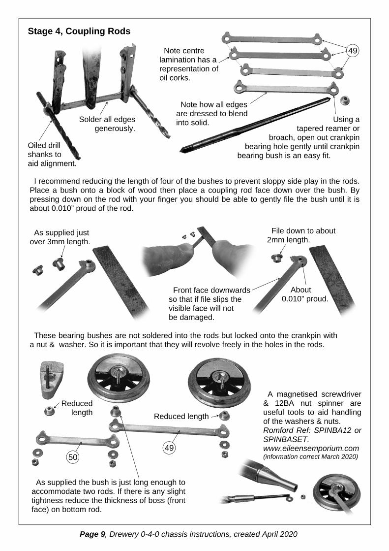
Using a tapered reamer or
broach, open out crankpin bearing hole gently until crankpin
bearing bush is an easy fit.
Stage 4, Coupling Rods
I recommend reducing the length of four of the bushes to prevent sloppy side play in the rods. Place a bush onto a block of wood then place a coupling rod face down over the bush. By pressing down on the rod with your finger you should be able to gently file the bush until it is about 0.010” proud of the rod.
These bearing bushes are not soldered into the rods but locked onto the crankpin with a nut & washer. So it is important that they will revolve freely in the holes in the rods.
A magnetised screwdriver & 12BA nut spinner are useful tools to aid handling of the washers & nuts. Romford Ref: SPINBA12 or SPINBASET. www.eileensemporium.com (information correct March 2020)
Solder all edges generously.
Oiled drill shanks to aid alignment.
Note centre lamination has a representation of oil corks.
Note how all edges are dressed to blend into solid.
49
As supplied just over 3mm length.
File down to about 2mm length.
Front face downwards so that if file slips the visible face will not be damaged.
About 0.010” proud.
Reduced length Reduced
length
As supplied the bush is just long enough to accommodate two rods. If there is any slight tightness reduce the thickness of boss (front face) on bottom rod.
49 50
Page 9, Drewery 0-4-0 chassis instructions, created April 2020

If using Slater’s plungers open pilot holes up to provide snug fit. Make up a sample pickup and using this check with sample wheel and
axle that pickup point will run correctly on back of flange avoiding V shaped notch.
Stage 5, Free Rolling Chassis
Included in packet with Slater’s pickups are (use if required) etched spacing washers. I fitted them but then dressed the faces back slightly.
If required bearings can be eased out, using tapered broache, to allow free revolving of axle. Packing washers (full & Half thickness) to reduce sideplay can be slipped onto axle end, always a good idea for gearwheel axle, if required on others. On this build I found a full thickness each side and a single half thickness one side only was about right but you may need half thickness both sides.
Fit reduced length bushes onto the crankpin screws & fit the wheelset coupling rods. Gently locking them into place with the washers and nuts. Check that the wheels will turn without
binding or tight spots.
At this stage you are looking to push the chassis along the bench without the wheels skidding. If not achieved remove a rod & using a tapered reamer or broach gently
open out each crankpin hole an equal amount. Try again & if required then repeat for rod on other side until satisfactory.
Remove wheelset rods, fit long bush on rear wheel crankpin & shortened onto flycrank, and repeat procedure for wheelset to flycrank rods.
Its usual for this operation to be required for most kit builds as during construction imperfections occur with each component fitted and these tend to compound. Its not precise but you will soon get the feel for what clearance is required for this technique.
To give you an idea, the turned bush is just over Ø2.4mm, on this build the wheelset rods required all four holes opening to Ø2.6mm & wheel to flycrank rods Ø2.7mm.
52
51
Page 10, Drewery 0-4-0 chassis instructions, created April 2020
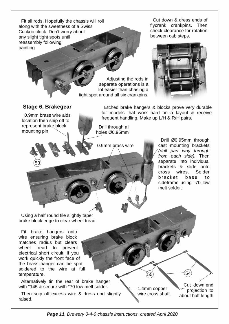
Fit all rods. Hopefully the chassis will roll along with the sweetness of a Swiss Cuckoo clock. Don’t worry about any slight tight spots until reassembly following painting
Adjusting the rods in separate operations is a lot easier than chasing a
tight spot around all six crankpins.
Cut down & dress ends of flycrank crankpins. Then check clearance for rotation between cab steps.
Stage 6, Brakegear
Drill through all holes Ø0.95mm
Etched brake hangers & blocks prove very durable for models that work hard on a layout & receive frequent handling. Make up L/H & R/H pairs.
Fit brake hangers onto wire ensuring brake block matches radius but clears wheel tread to prevent electrical short circuit. If you work quickly the front face of the brass hanger can be spot soldered to the wire at full temperature.
Alternatively tin the rear of brake hanger with °145 & secure with °70 low melt solder.
Then snip off excess wire & dress end slightly raised.
0.9mm brass wire aids location then snip off to represent brake block mounting pin
53
0.9mm brass wire
Using a half round file slightly taper brake block edge to clear wheel tread.
Drill Ø0.95mm through cast mounting brackets (drill part way through from each side). Then separate into individual brackets & slide onto cross wires. Solder b r a c k e t b a s e t o sideframe using °70 low melt solder.
54 55
1.4mm copper wire cross shaft.
Cut down end projection to
about half length
Page 11, Drewery 0-4-0 chassis instructions, created April 2020
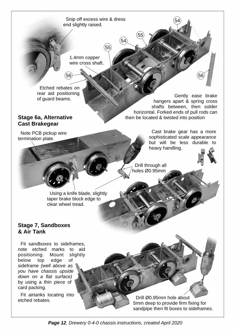
Gently ease brake hangers apart & spring cross
shafts between, then solder horizontal. Forked ends of pull rods can
then be located & twisted into position Stage 6a, Alternative Cast Brakegear
1.4mm copper wire cross shaft.
Etched rebates on rear aid positioning of guard beams.
Cast brake gear has a more sophisticated scale appearance but will be less durable to heavy handling.
Snip off excess wire & dress end slightly raised.
Note PCB pickup wire termination plate.
54
56
55
54
56
55
Using a knife blade, slightly taper brake block edge to clear wheel tread.
Drill through all holes Ø0.95mm
Stage 7, Sandboxes & Air Tank
Fit sandboxes to sideframes, note etched marks to aid positioning. Mount slightly below top edge of sideframe (well above as you have chassis upside down on a flat surface) by using a thin piece of card packing.
Fit airtanks locating into etched rebates. Drill Ø0.95mm hole about
5mm deep to provide firm fixing for sandpipe then fit boxes to sideframes.
Page 12, Drewery 0-4-0 chassis instructions, created April 2020

3mm 12.5mm 3mm
18mm
Chassis width About 25mm
Taper edge.
Wiring from pickups can be connected direct to the
motor tags but there is wisdom in having a termination plate.
Stage 8, Pickups & Electrics
Solder PCB plate to sideframes, inside faces.
Use packing (coffee stirers)
to slightly set termination plate below
sideframe tops.
About 9mm between casting & bend.
Note how boxes are mounted slightly below top edge of sideframe.
8mm Insulating gaps made with triangular file
Note double sided PCB, wire termination plate, positioned slightly below sideframe tops.
0.9mm brass wire sand pipes, fit over length to aid manipulation & positioning, then trim to clear rail top.
A suggestion for a wire wiper pickup system.
PCB Pickup plate
Wire loops filled with solder.
0.45mm spring brass wire. Fit over length to aid positioning & application of slight spring tension on wheel back. Then spot solder into position.
Wire formed to pass over brake pull rods.
Page 13, Drewery 0-4-0 chassis instructions, created April 2020

Fit electrical wire to run through holes back to motor/terminal plate. Snip off over length wire tails & tidy up. Check that there is sufficient electrical clearance to avoid a short circuit through chassis components.
I would now recommend removing wheelsets, masking off the wire loop pickup ends, & spray painting the entire chassis, including pickups, with primer & black.
If fitting Slater’s plunger pickups, my preference, I would still recommend painting the chassis now.
During reassembly I would fit the Slater’s plunger pickups and wiring. If you are not familiar with the techniques for fitting pickups, motor & achieving a sweet running chassis. Then on my website (www.jimmcgeown.com/Print Outs.html) downloadable detailed help sheets cover these operations in full detail or please contact me for a free copy of my hints and tips booklet.
PCB soldered to sideframe.
Solder lengths of wire (around 90mm long) to the tags included with Slater’s pickups. Then snip out of fret to separate.
Wire & tags are fitted to plungers by locking between 12BA nuts.
Then threaded through chassis holes. Wheels & gear are fitted & plunger
operation checked.
Flying leads soldered to motor terminal tags.
Page 14, Drewery 0-4-0 chassis instructions, created April 2020

When you are satisfied that the chassis runs like that Swiss Cuckoo clock, don't forget to oil all bearings with light oil & thick oil on gearset, then Electricians tape moulded over the motor will tidy away the electrical wires. Final job is to snip off excess crankpin screw & dress down to the nut with a flat file.
Painting is covered in more detail in my downloadable hints and tips booklet, (www.jimmcgeown.com/Print Outs.html) or please contact me for a free printed copy of my hints and tips booklet. This chassis has been painted using, rattle can type, car touch up spray paint from Halfords (their own brand). Undercoat with, grey, Etch Primer & finish with Matt Black.
Secure pickup housings with a dab of Araldite applied using a match stick onto the inside face of
the sideframes. When hardened reassemble flycranks & rods & check for free running.
Sometimes swapping wheels around will address any tightspot that may have
appeared but if unsuccessful find the tight rod and slightly oval
the crankpin holes with a round file. Then route
w i r e s t o t e r m i n a t i o n
plate & fit motor.
Flying leads from motor should be positioned for ease of unsoldering so that they can be swapped over to change motor direction. I leave a generous loop of wire from the pickups to make handling easier when soldering at the PCB termination plate.
Stage 9, reassembly & Finishing
Page 15, Drewery 0-4-0 chassis instructions, created April 2020
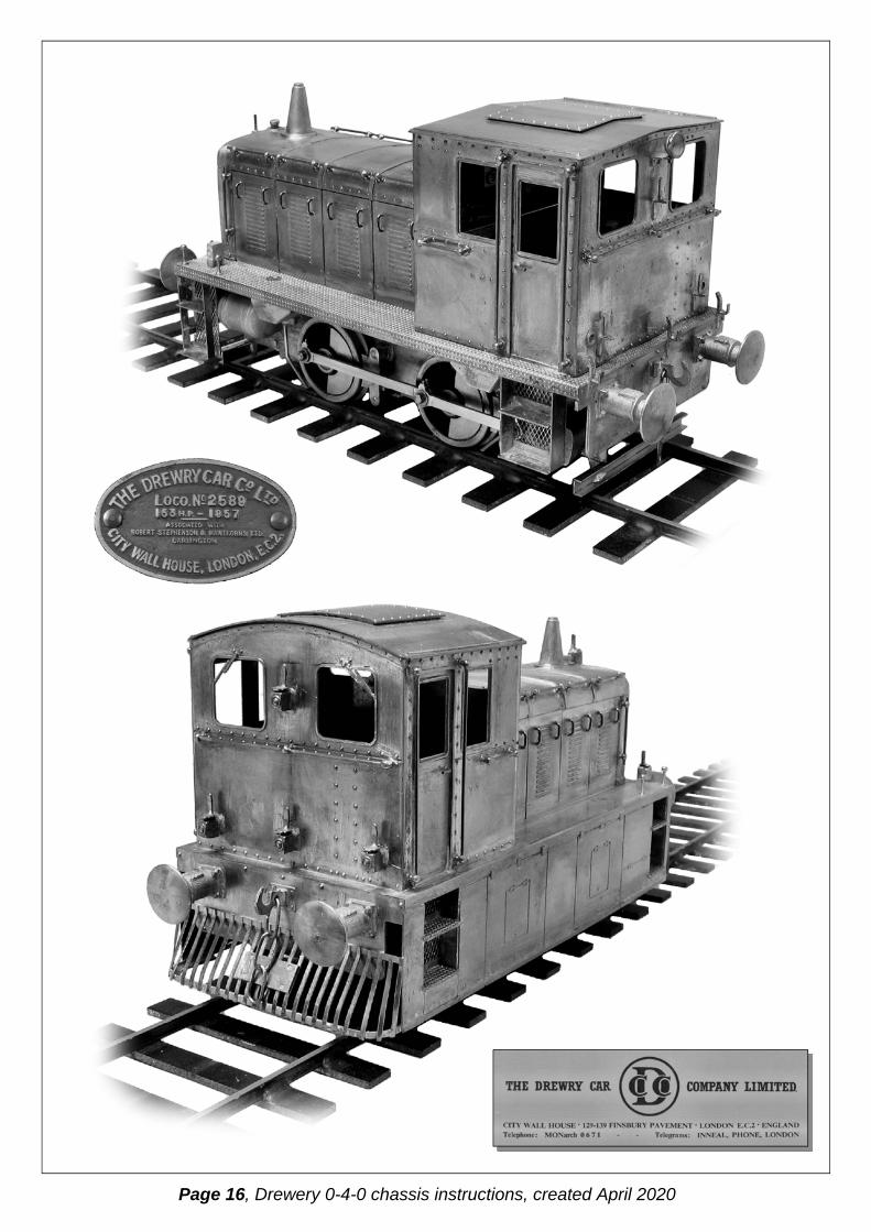
Page 16, Drewery 0-4-0 chassis instructions, created April 2020