! why do women like having their nipples licked !
TRANSCRIPT

188 IEEE TRANSACTIONS ON SMART GRID, VOL. 5, NO. 1, JANUARY 2014
Joint Optimization of Electric Vehicle andHome Energy Scheduling Considering
User Comfort PreferenceDuong Tung Nguyen and Long Bao Le, Senior Member, IEEE
Abstract—In this paper, we investigate the joint optimization ofelectric vehicle (EV) and home energy scheduling. Our objective isto minimize the total electricity cost while considering user com-fort preference. We take both household occupancy and EV travelpatterns into account. The novel contributions of this paper lie inthe exploitation of EVs as dynamic storage facility as well as de-tailed modeling of user comfort preference, thermal dynamics, EVtravel, and customer occupancy patterns in a concrete optimiza-tion framework. Extensive numerical results are presented to illus-trate the efficacy of the proposed design. Specifically, we show thatthe proposed design can achieve significant saving in electricitycost, allow more flexibility in setting the tradeoff between cost anduser comfort, and enable to reduce energy demand during peakhours. We also demonstrate the benefits of applying the proposedframework to a residential community compared to optimizationof individual household separately.
Index Terms—Electric vehicle, HVAC system, energy manage-ment system, aggregator, day-ahead electricity price, occupancypattern, travel pattern, cost minimization, user comfort.
NOMENCLATURE
Duration of time slot (hours).
Maximum acceptable temperature deviation whenhouse is occupied ( C).
Coefficient of performance (COP) of heater/ACin house .
Charging efficiency of EV .
Discharging efficiency of EV .
Travel time of EV during trip .
Solar irradiance in time slot (kW/m ).
Dummy variable, “ ” for AC cooling, “1” forheating.
The effective window area of house .
Manuscript received November 22, 2012; revised May 07, 2013; acceptedJuly 18, 2013. Date of publication September 12, 2013; date of current versionDecember 24, 2013. Paper no. TSG-00810-2012.The authors are with the Institut National de la Recherche Scientifique—Én-
ergie, Matériaux et Télécommunications (INRS-EMT), Université du Québec,Montréal, QC H5A 1K6, Canada (e-mail: [email protected]; [email protected]).Color versions of one or more of the figures in this paper are available online
at http://ieeexplore.ieee.org.Digital Object Identifier 10.1109/TSG.2013.2274521
Occupancy state of house in time slot , “1” foroccupied, “0” otherwise.
Availability state of EV in time slot , “1” forparking at home, “0” otherwise.
Thermal capacitance (kWh/ C).
Travel distance of EV during trip (mile).
Electricity price at time slot ($/kWh).
Battery capacity of EV (kWh).
Time slot index, .
Number of EVs in house .
Household index, .
Number of households.
Travel efficiency of EV (kWh/mile).
Number of time slots.
Imported power from the grid during time slot(kW).
Power rating of heater/AC in house (kW).
Output power of heater/AC in house at time slot(kW).
Power supplied to heater/AC in house at timeslot (kW).
Charging power of EV at time slot (kW).
Discharging power of EV at time slot (kW).
Maximum charging power of EV (kW).
Maximum discharging power of EV (kW).
The fraction of solar radiation entering the innerwalls and floor.
Thermal resistance between two heat exchangemedia ( C/kW).
State of charge of EV at time slot .
Maximum allowable state of charge of EV .
Minimum allowable state of charge of EV .
Ambient temperature in time slot ( C).
1949-3053 © 2013 IEEE

NGUYEN AND LE: JOINT OPTIMIZATION OF ELECTRIC VEHICLE AND HOME ENERGY SCHEDULING 189
Desired indoor temperature of house in timeslot ( C).
The temperature of the house envelope ( C).
Indoor temperature of house in time slot ( C).
The temperature of the thermal accumulatinglayer in the inner walls and floor ( C).
Time slot index when EV leaves home for trip.
Time slot index when EV returns home fortrip .
Weighting coefficient between electricity cost anddiscomfort cost for house C).
I. INTRODUCTION
D EMAND SIDEmanagement in the residential sector (i.e.,residential buildings) is an important research topic since
buildings contribute a significant fraction of overall electricityconsumption. In fact, it accounted for 72% of total U.S. en-ergy consumption in 2006 out of that residential buildings ac-counted for 51% according to the U.S. Environmental Protec-tion Agency (EPA) [1]. This research topic has received lots ofattention from the research community [2]–[8]. In [2], Shengnanet al. assessed the use of demand response as a load shaping toolto improve the distribution transformer utilization and avoidoverloading for the transformer. Mohsenian-Rad et al. [3] pro-posed an optimization framework that aims to minimize elec-tricity bills considering user comfort. However, the assumptionon homogeneous appliances and using waiting time to representuser comfort in this paper would be too simple to represent dif-ferent characteristics of home appliances and user requirements.In a typical household, thermostatically controlled appliances
(TCAs) including refrigerator, electric water heater, and theheating, ventilation, and air-conditioning (HVAC) system ac-count for more than half of total residential energy consumption[1]. Research on optimal control for TCA loads has been a hotresearch topic in the last several years. References [4] and [5]proposed optimal control schemes to minimize the electricitycost for the HVAC system considering user climate comfort.Dynamic programming was employed in [6] to compare severaloptimal control algorithms applied to a thermostat. In [7], theauthors introduced an appliance commitment algorithm thatschedules electric water heater power consumption to minimizeuser payment.Electric vehicle (EV) is another important grid element that
has significant economic and environmental advantages com-pared to normal cars. The penetration of EVs is expected to in-crease drastically in the next few years, which can reach onemillion by 2015 in US [9]. Therefore, EV charging will havesignificant impacts on the power distribution network if it isnot controlled appropriately [10]–[12]. EV travel pattern is animportant factor to model potential impacts of EVs on the grid[13], [14] and to develop efficient EV charging strategies [15].Given electricity prices and EV driving pattern, Rotering et al.proposed a dynamic programming based control scheme to opti-mize the charging for one EV [16]. In [17], Wu et al. consideredload scheduling and dispatch problem for a fleet of EVs in both
the day-ahead market and real-time energy market. In [18], anoptimal charging strategy for EVs was proposed that considersvoltage and power constraints.The problems of scheduling of home energy usage and EV
charging are often addressed separately in the literature. In thispaper, we propose a unified optimization model that jointly op-timizes the scheduling of EVs and TCAs. In particular, we uti-lize EVs as dynamic storage facility to supply energy for resi-dential buildings during peak hours where energy can be trans-ferred from EVs to charge other EVs and to provide energy forHVAC in a residential community. Our proposed model aimsto minimize the total electricity cost considering user comfort,house occupancy and EV travel patterns, thermal dynamics, EVelectricity demand, and other operation constraints. There aresome recent works that discuss potential benefits of vehicle tobuilding interactions [19], [20]. However, to the best of ourknowledge, none of previous works have considered detaileddesign and joint optimization of EV and building energy man-agement. The main contributions of this paper can be summa-rized as follows:• We propose a comprehensive model to optimize the EVand HVAC scheduling in a residential area. The formula-tion aims to achieve flexible tradeoff between minimizingtotal electricity cost and maintaining user comfort pref-erence. The model accounts for the characteristics of theHVAC system, thermal dynamics, user climate comfortpreference, battery state model, user travel patterns, andhousehold occupancy patterns. We also discuss potentialextensions of the proposed framework to capture variousmodeling uncertainty factors.
• We show the impacts of different design and system param-eters, which control the electricity cost and user comfort,on the system operation and performance as well as theeconomic benefits of applying our proposed control frame-work compared to a non-optimized control scheme for asingle-house scenario.
• We illustrate the advantages of applying the proposed con-trol model for the multiple-house scenario compared tothe case where each household optimizes its energy con-sumption separately. Specifically, we demonstrate that op-timization of EV and home energy scheduling for multiplehouses in a residential community can achieve the signif-icant saving in electricity cost and reduce the high powerdemand during peak hours.
The remaining of this paper is organized as follows. Thesystem model is presented in Section II. Thermal dynamicsmodel is described in Section III. Detailed problem formulationis described in Section IV. The case studies and numericalresults are provided in Section V followed by conclusion inSection VI.
II. SYSTEM MODEL
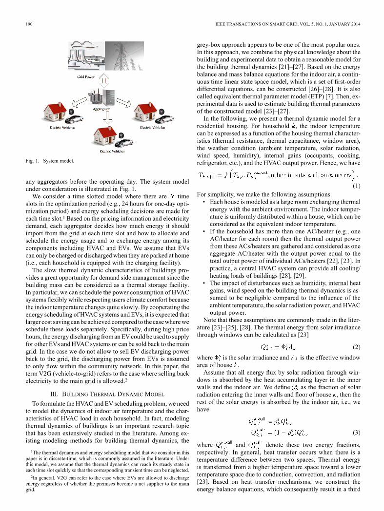
We consider the interaction among EVs and HVAC systemsin the residential community. We assume that there is an ag-gregator that collects all required information from EVs andHVAC systems from all households to make control decisions.At the higher level, several aggregators can be connected to acentral aggregator that coordinates the overall operations andparticipates in the wholesale day-ahead electricity market. Theday-ahead market clearing price is assumed to be available to
190 IEEE TRANSACTIONS ON SMART GRID, VOL. 5, NO. 1, JANUARY 2014
Fig. 1. System model.
any aggregators before the operating day. The system modelunder consideration is illustrated in Fig. 1.We consider a time slotted model where there are time
slots in the optimization period (e.g., 24 hours for one-day opti-mization period) and energy scheduling decisions are made foreach time slot.1 Based on the pricing information and electricitydemand, each aggregator decides how much energy it shouldimport from the grid at each time slot and how to allocate andschedule the energy usage and to exchange energy among itscomponents including HVAC and EVs. We assume that EVscan only be charged or discharged when they are parked at home(i.e., each household is equipped with the charging facility).The slow thermal dynamic characteristics of buildings pro-
vides a great opportunity for demand side management since thebuilding mass can be considered as a thermal storage facility.In particular, we can schedule the power consumption of HVACsystems flexibly while respecting users climate comfort becausethe indoor temperature changes quite slowly. By cooperating theenergy scheduling of HVAC systems and EVs, it is expected thatlarger cost saving canbe achieved compared to the casewhereweschedule these loads separately. Specifically, during high pricehours, the energydischarging fromanEVcould beused to supplyfor other EVs andHVAC systems or can be sold back to themaingrid. In the case we do not allow to sell EV discharging powerback to the grid, the discharging power from EVs is assumedto only flow within the community network. In this paper, theterm V2G (vehicle-to-grid) refers to the case where selling backelectricity to the main grid is allowed.2
III. BUILDING THERMAL DYNAMIC MODEL
To formulate the HVAC and EV scheduling problem, we needto model the dynamics of indoor air temperature and the char-acteristics of HVAC load in each household. In fact, modelingthermal dynamics of buildings is an important research topicthat has been extensively studied in the literature. Among ex-isting modeling methods for building thermal dynamics, the
1The thermal dynamics and energy scheduling model that we consider in thispaper is in discrete-time, which is commonly assumed in the literature. Underthis model, we assume that the thermal dynamics can reach its steady state ineach time slot quickly so that the corresponding transient time can be neglected.2In general, V2G can refer to the case where EVs are allowed to discharge
energy regardless of whether the premises become a net supplier to the maingrid.
grey-box approach appears to be one of the most popular ones.In this approach, we combine the physical knowledge about thebuilding and experimental data to obtain a reasonable model forthe building thermal dynamics [21]–[27]. Based on the energybalance and mass balance equations for the indoor air, a contin-uous time linear state space model, which is a set of first-orderdifferential equations, can be constructed [26]–[28]. It is alsocalled equivalent thermal parameter model (ETP) [7]. Then, ex-perimental data is used to estimate building thermal parametersof the constructed model [23]–[27].In the following, we present a thermal dynamic model for a
residential housing. For household , the indoor temperaturecan be expressed as a function of the housing thermal character-istics (thermal resistance, thermal capacitance, window area),the weather condition (ambient temperature, solar radiation,wind speed, humidity), internal gains (occupants, cooking,refrigerator, etc.), and the HVAC output power. Hence, we have
(1)For simplicity, we make the following assumptions.• Each house is modeled as a large room exchanging thermalenergy with the ambient environment. The indoor temper-ature is uniformly distributed within a house, which can beconsidered as the equivalent indoor temperature.
• If the household has more than one AC/heater (e.g., oneAC/heater for each room) then the thermal output powerfrom these ACs/heaters are gathered and considered as oneaggregate AC/heater with the output power equal to thetotal output power of individual ACs/heaters [22], [23]. Inpractice, a central HVAC system can provide all cooling/heating loads of buildings [28], [29].
• The impact of disturbances such as humidity, internal heatgains, wind speed on the building thermal dynamics is as-sumed to be negligible compared to the influence of theambient temperature, the solar radiation power, and HVACoutput power.
Note that these assumptions are commonly made in the liter-ature [23]–[25], [28]. The thermal energy from solar irradiancethrough windows can be calculated as [23]
(2)
where is the solar irradiance and is the effective windowarea of house .Assume that all energy flux by solar radiation through win-
dows is absorbed by the heat accumulating layer in the innerwalls and the indoor air. We define as the fraction of solarradiation entering the inner walls and floor of house , then therest of the solar energy is absorbed by the indoor air, i.e., wehave
(3)
where and denote these two energy fractions,respectively. In general, heat transfer occurs when there is atemperature difference between two spaces. Thermal energyis transferred from a higher temperature space toward a lowertemperature space due to conduction, convection, and radiation[23]. Based on heat transfer mechanisms, we construct theenergy balance equations, which consequently result in a third
NGUYEN AND LE: JOINT OPTIMIZATION OF ELECTRIC VEHICLE AND HOME ENERGY SCHEDULING 191
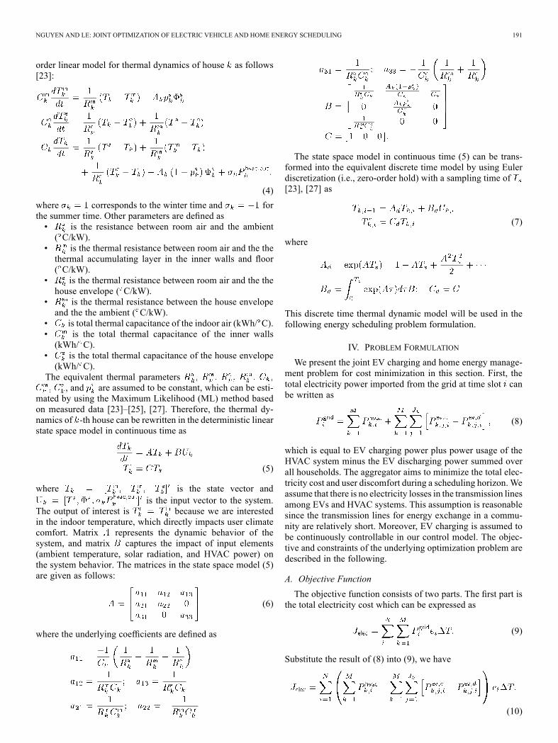
order linear model for thermal dynamics of house as follows[23]:
(4)
where corresponds to the winter time and forthe summer time. Other parameters are defined as• is the resistance between room air and the ambient( C/kW).
• is the thermal resistance between room air and the thethermal accumulating layer in the inner walls and floor( C/kW).
• is the thermal resistance between room air and the thehouse envelope ( C/kW).
• is the thermal resistance between the house envelopeand the the ambient ( C/kW).
• is total thermal capacitance of the indoor air (kWh/ C).• is the total thermal capacitance of the inner walls(kWh/ C).
• is the total thermal capacitance of the house envelope(kWh/ C).
The equivalent thermal parameters, and are assumed to be constant, which can be esti-
mated by using the Maximum Likelihood (ML) method basedon measured data [23]–[25], [27]. Therefore, the thermal dy-namics of -th house can be rewritten in the deterministic linearstate space model in continuous time as
(5)
where is the state vector andis the input vector to the system.
The output of interest is because we are interestedin the indoor temperature, which directly impacts user climatecomfort. Matrix represents the dynamic behavior of thesystem, and matrix captures the impact of input elements(ambient temperature, solar radiation, and HVAC power) onthe system behavior. The matrices in the state space model (5)are given as follows:
(6)
where the underlying coefficients are defined as
The state space model in continuous time (5) can be trans-formed into the equivalent discrete time model by using Eulerdiscretization (i.e., zero-order hold) with a sampling time of[23], [27] as
(7)
where
This discrete time thermal dynamic model will be used in thefollowing energy scheduling problem formulation.
IV. PROBLEM FORMULATION
We present the joint EV charging and home energy manage-ment problem for cost minimization in this section. First, thetotal electricity power imported from the grid at time slot canbe written as
(8)
which is equal to EV charging power plus power usage of theHVAC system minus the EV discharging power summed overall households. The aggregator aims to minimize the total elec-tricity cost and user discomfort during a scheduling horizon. Weassume that there is no electricity losses in the transmission linesamong EVs and HVAC systems. This assumption is reasonablesince the transmission lines for energy exchange in a commu-nity are relatively short. Moreover, EV charging is assumed tobe continuously controllable in our control model. The objec-tive and constraints of the underlying optimization problem aredescribed in the following.
A. Objective Function
The objective function consists of two parts. The first part isthe total electricity cost which can be expressed as
(9)
Substitute the result of (8) into (9), we have
(10)

192 IEEE TRANSACTIONS ON SMART GRID, VOL. 5, NO. 1, JANUARY 2014
The second part of the objective function is the discomfort cost.It is assumed that each household will inform its preferredtemperature for each time slot when the house is occupiedand amaximum acceptable deviation to the aggregator. Then,the aggregator controls the power supplied to HVAC system sothat the temperature lies within the acceptable range
in each occupied house . The closer to the desiredtemperature, the more comfortable users would be. There is noindoor temperature constraint for the period when the house isunoccupied. The power supplied to an HVAC system at timeslot will decide the temperature at time slot , which con-sequently affects user comfort at time slot but time slot .Therefore, we define the discomfort cost function as
(11)
where represents the occupancy status of house at timeslot . If , the discomfort cost for house at timeslot is equal to zero regardless of the indoor temperature atthat time slot because the house is not occupied. The weightingfactor can be viewed as the price ($) that aggregator has topay household when the temperature in house deviates 1C from the desired temperature in each time slot. The value ofwill influence the optimal solution of the underlying opti-
mization problem. The objective function, which is the sum ofelectricity cost and the discomfort cost, can be written as fol-lows:
(12)
We are now ready to describe all constraints for the consideredoptimization problem.
B. Thermal Constraints
1) Thermal Dynamics Model: The thermal dynamics modelfor a residential house has been presented in Section III. It canbe seen from (7), for each household, the indoor temperature atthe next time slot is determined by the current indoor tempera-ture , the current outdoor temperate , the solar radi-ation power , and the output power of the HVAC system
at the current time slot. The output power is related to
the power supplied to the HVAC system aswhere is the performance coefficient of the HVAC system inhousehold . The discrete time thermal dynamic model (7) rep-resents one constraint of the considering optimization problem
.2) Temperature Constraints: Each household informs its de-
sired temperature to the aggregator. Then, the aggregator con-trols power supplied to the HVAC system in the house at eachtime slot to keep the indoor temperature as close as possibleto the desired temperature. The indoor temperature requirementfor each house is expressed as
(13)
for and . There is no temper-ature requirement when a house is not occupied. Note that thepower provided to an HVAC system in the current time slot willaffect the indoor temperature in the next time slot, so the tem-perature constraint is only applied from the second time slot.3) HVAC Power Constraints: The power supplied to an
HVAC system cannot be negative and it cannot take valuesgreater than the heater/AC’s power rating. Therefore, we have
(14)
for and .Remark 1: In our proposed system model, each household
needs to report its desired temperature at each time slot duringwhich the household is occupied as well as the level of discom-fort (i.e., parameters ) to the aggregator to determine the op-timal control solution. In practice, if a particular user does notwish to report its desired temperature in the occupied time slotsto the aggregator then the aggregator can simply choose a typ-ical temperature value for this household to calculate the op-timal solution.
C. SOC and Charging Power Constraints
For EVs, we need to model the characteristics and the travelpatterns for each EV. In particular, we are interested in the bat-tery capacity (kW), the travel efficiency (kWh/mile), and thecharging type. These properties can be retrieved from the man-ufacturer’s website. The travel pattern of each EV can be de-scribed by the number of trips per day, the starting and endingtimes, and the travel distance of each trip. A trip is defined as thetime period between the instants when the EV leaves and arriveshome. This information is related to user traveling schedule,which can be sent by users to the aggregator before the oper-ating day. In Section V, we use the real-world travel pattern datafrom the 2009 National Household Travel Survey [30] to buildtravel patterns used to obtain numerical results.1) SOC Dynamics: Assume that each EV of house can
take several trips during the optimization period (e.g., one day).Let and be the time slots when EV of houseleaves and arrives home for trip , respectively. Then, we havefollowing constraints
(15)
(16)
(17)
Here, the SOC for EV of house changes according to thecharging and discharging powers when it parks at home (15) andthe difference of SOCs at leaving and returning home instantsaccounts for the energy usage in driving (16). Equation (17) en-sures that the SOC level is non-increasing when an EV travels.2) SOC Constraints: To maintain long lifetime of battery, an
EV should maintain its battery level within a certain range that

NGUYEN AND LE: JOINT OPTIMIZATION OF ELECTRIC VEHICLE AND HOME ENERGY SCHEDULING 193
is recommended by its manufacturer [31]. Therefore, we imposethe following constraints
(18)
where and denote the minimum and max-imum recommended SOCs for EV of house .3) Charging and Discharging Constraints: We assume that
an EV is only charged or discharged when it is parked at home.Moreover, EVs are connected to home chargers as soon as theyarrive home. Therefore, constraints on charging and dischargingpower applied to only time slots when an EV is parked at homeas
(19)
where represents the availability of EV of house athome during time slot and denote the max-imum charging and discharging limits, respectively. From theseconstraints, the charging and discharging powers for each EVof household (i.e., and ) are equal zero if the EVis not at home (i.e., as ).
D. Grid Constraints
If it is not allowed to sell EV discharging energy back to themain grid, the energy imported from the grid in each time slotmust be non-negative and it must be upper-bounded by somepredetermined limit. Hence, we have
(20)
or
(21)
where is the maximum power that can be imported fromthe grid, which can be a contracted amount between the aggre-gator and the grid, or a particular parameter capturing grid con-ditions over time. In contrast, if the selling EV discharging en-ergy service is allowed and the maximum power that can be soldback to the main grid is equal to . Then, we have the fol-lowing constraint
(22)
For simplicity, we assume that the selling back electricity priceis equal to the buying electricity price. In summary, we can for-mulate the EV charging and HVAC scheduling to minimize thecost function given in (12) as
(23)
where the optimization variables are , and .Despite the absolute term in the objective function of our model,this optimization problem can be transformed into an equivalentlinear program by introducing some auxiliary variables [32].Thus, the aggregator can easily calculate and implement its op-timal solution upon collecting all required information.It can be observed that we do not impose constraints in the
optimization problem (23) to prevent any EV of house fromcharging and discharging simultaneously at any time slot (i.e.,
and for any EV of house are both positive at thesame time slot ). In fact, this is not needed since the optimalsolution of (23) always satisfies these hidden constraints.
E. Extensions to Consider Modeling Uncertainties and OtherResidential Loads
In the above formulation, we have assumed that all modelingparameters such as outdoor temperature, household occupancypattern, and EV travel pattern are known without errors and thethermal dynamics model is perfect. In practice, they have tobe estimated with potential errors. We can employ the ModelPredictive Control (MPC) technique to tackle these estimationuncertainties [33], which can be implemented as follows. TheMPC controller solves the minimization problem (23) for theprediction horizon from current time slot to time slotwith assumption that estimated parameters are certain ones
(i.e., no estimation errors). The uncertainties are compensatedby refinement and update of the prediction at each time step. Thesequences of control variables such as power consumption ofHVAC and EVs are calculated for the whole prediction horizon;however, the controller applies only the control action for thefirst time slot. The MPC controller repeats the process at nexttime step, solving new optimization with the most updated datafor the new time horizon shifted one step forward.We have only considered EVs and HVAC systems in our
proposed optimization framework so far. However, integrationof other types of residential loads into this framework is pos-sible. Moreover, extension of our system model to consider dis-tributed renewable energy sources is also possible. Here, theMPC technique can be employed again to tackle the uncer-tainty due to the intermittent nature of the underlying renewablesources (e.g., wind or solar energy).
V. NUMERICAL RESULTS
We present numerical results to illustrate the desirable per-formance of the proposed framework. We assume that the out-door temperature and solar irradiance can be predicted perfectly.The temperature data is taken fromWeather Underground web-site [34], and the solar irradiance data is taken from the Renew-able Resource Data Center (RReDC) website [35]. Solar radi-ation power contributes to increase the indoor house tempera-ture; therefore, it results in more cooling energy needed in thesummer and less heating energy needed in the winter. Moreover,the solar irradiance is low during the winter months and highduring summer months as we can observe in Fig. 2(d). Hence,

194 IEEE TRANSACTIONS ON SMART GRID, VOL. 5, NO. 1, JANUARY 2014
the decreasing amount of heating energy required in the winteris relatively small compared to the increasing amount of coolingenergy needed in the summer.For the electricity price data, we use day-ahead pricing data
retrieved from PJM [36]. We will first evaluate the performanceof our control scheme for a single-house scenario. Then, weinvestigate the benefits of applying the control strategy in themultiple-house setting. Results for the single-house scenarioare presented to reveal insights into the interaction among theHVAC system, EV, pricing, and temperature patterns.When solving the joint scheduling optimization for EVs and
HVAC systems we set and for all corre-sponding to the summer and winter time, respectively. The op-timization period is one day with 24 time slots each of whichis one hour ( ). Fig. 2(a) shows the day-ahead electricity prices of a typical summer and winter week-days, which are used to obtain numerical results. Three differenttemperature profiles for summer days (very hot, hot, mild) andwinter days (very cold, cold, mild) are considered to representthe diversity of weather conditions, as shown in Fig. 2(b) and(c), respectively. The average hourly solar irradiance profiles forthe summer and winter cases used in the simulation are shownin Fig. 2(d). We use CVX [37] to solve the proposed optimiza-tion problem.
A. Single-House Scenario
We analyze the performance due to our proposed optimalscheme to the single-house scenario. For simplicity, we assumethat the considering residential house has only one EV and oneHVAC where the varying ownership aspect will be capturedlater in Section V-B for the multiple-house case. The housingthermal parameters including , andare taken from [23]. We assume that the house is equipped
with a heat pump which can be operated in both heating andcooling modes. The parameters of the heat pump are set asfollows: power rating kW and HVAC coeffi-cient of performance (COP) . We consider Nissan LeafEVs whose specifications are obtained from [31] with the fol-lowing parameter setting: battery capacity of 24 kWh; max-imum charging and discharging power ( and )are set equally to 6 kW [38]; charging and discharging efficiencyfactors ( and ) are both set equal to 0.9; travel efficiencyis 0.316 kWh/mile; and . Theinitial SOC of the EV is set equal to 0.5. To obtain numericalresults for the single-house scenario, we simply set inall related constraints and quantities.We assume that the EV’s owner leaves home at 8 A.M. and
comes back at 5 P.M. Driving distance is assumed to be 32miles, which is the average daily travel distance in the U.S.[17], [30], [41]. This is a typical driving pattern [16] in the U.S.,which is used to obtain the numerical results in several scenariosbelow. However, other different driving patterns are also exam-ined where we will investigate the impacts of varying departuretime, arrival time, and travel distance on the optimal solution.In addition to the above parameter settings for HVAC systemand EV, the power limit is set equal to 25 kW. The desiredindoor temperature in summer days and winter days are 23 Cand 21 C, respectively. Initial temperature at 0 A.M. is assumed
Fig. 2. Electricity price and weather profiles. (a) Day-ahead electricity price.(b) Summer temperature profiles. (c) Winter temperature profiles. (d) Solar ir-radiance.
to be equal to the desired indoor temperature. Assuming that theconsidered house is occupied all day, so the desired indoor tem-perature is equal to 23 C (summer) or 21 C (winter) at everytime slot.

NGUYEN AND LE: JOINT OPTIMIZATION OF ELECTRIC VEHICLE AND HOME ENERGY SCHEDULING 195
Fig. 3. Impacts of parameters and on electricity cost (No V2G).(a) Summer (very hot). (b) Winter (cold).
Fig. 3(a) and (b) show the impacts of parameters and onthe total electricity cost in a summer day and a winter day, re-spectively. The weighting factor is varied in a certain interval,and takes one of three values: 1 C, 2 C, and 3 C. To en-force the stricter user comfort requirement, we would choosea higher value for and a smaller value for . These figuresshow that the electricity cost increases as increases. Thisis intuitive since the cost of electricity increases with stricteruser comfort requirement. Moreover, for small values of (i.e.,
C for the summer day, and C for thewinter day), the electricity cost decreases as increases. This isbecause small values of allow the indoor temperature to de-viate more significantly from the preferred value to save elec-tricity cost, especially for large values of . However, as be-comes sufficiently large (i.e., C for the summer day,and C for the winter day), the electricity costs cor-responding to the three different values of are the same. This isbecause sufficiently high values of penalty value results in thetemperature being close to the desired value for the whole day.These figures also show that the electricity cost due to optimalcontrol without discharging is much higher than that exploitingEV discharging capability. This result confirms the great bene-fits of exploiting interactions among EVs and between EVs andHVAC systems. To obtain numerical results for the optimal con-trol without discharging, we simply set maximum dischargingpower to zero in our problem formulation.Due to the space constraint, we consider only the summer
case to present other numerical results in the following. Fig. 4(a)
Fig. 4. Impacts of parameters and on indoor temperature (No V2G).(a) Impact of on indoor temperature ( C). (b) Impact of on indoortemperature ( C).
illustrates the indoor temperature variation over time forC and different values of . This figure confirms our ob-
servation from Fig. 3(a) where higher values of reduce thefluctuation of indoor temperature around its preferred value. InFig. 4(b) we plot the indoor temperature over time for a fixedand different values of . This figure again indicates that the
indoor temperature oscillates more around the preferred valueas increases.Fig. 5(a) shows the power imported from the grid under our
control scheme exploiting EV discharging capability comparedto optimal solution without discharging and the uncontrolledscheme in the summer day. For the uncontrolled scheme, EVcharging occurs at midnight when EV is plugged, regardlessof electricity price. The charging terminates when the EVmeets the energy consumption requirement for the day. Forfair comparison, the energy charged to EV is chosen so thatthe remaining energy in the EV battery at the end of the dayequal to the energy in the controlled case. In addition, forthe uncontrolled case, the AC is controlled by a thermostat tokeep the indoor temperature equal to the desired temperatureat every time slots. It can be observed that our optimal schemewith discharging reduces the significantly load during peakhours (from 2 P.M. to 9 P.M.) when the electricity price is veryhigh [cf. Fig. 2(a)]. The negative value of imported power inthe V2G case represents the power selling back to the grid.To supply energy for the HVAC system, the EV discharges itsremaining battery right after it arrives home as indicated inFigs. 5(b), (c). Moreover, during high-price hours the amount

196 IEEE TRANSACTIONS ON SMART GRID, VOL. 5, NO. 1, JANUARY 2014
Fig. 5. Imported power and power consumption (very hot day, C,C). (a) Imported power. (b) Power consumption, charging/discharging
(No V2G). (c) Power consumption, charging/discharging (V2G).
of the EV discharging power for the V2G case in Fig. 5(c)is much higher than the amount of the EV discharging powerwithout V2G service in Fig. 5(b). EV charging occurs at timeslots when electricity prices are low (from 3 A.M. to 4 A.M.).In Figs. 6(a), (b), we present the impacts of different temper-
ature profiles on electricity cost saving compared to the uncon-trolled scheme in a summer day. It can be observed that the costsaving decreases with increasing since larger values of re-duces the flexibility in controlling HVAC consumption. Also,the absolute cost saving in dollars is larger for a hot or veryhot day than that for a mild day. This is because more EV dis-charging energy to the HVAC system would be expected in ahot or very hot day, which translates into more significant costsaving. Fig. 6(b) shows that for a small value of (e.g., less than0.04 C), the cost saving of more than 25% can be achieved
Fig. 6. Impact of temperature profiles and on cost saving (No V2G,C). (a) Absolute cost saving. (b) Relative cost saving.
in a mild or hot day where the relative cost saving is calculatedas
%
We illustrate the absolute and relative cost saving com-pared to the uncontrolled scheme versus users’ arrival anddeparture times for different summer temperature profiles inFigs. 7(a), (b), (c), (d), respectively. These figures show thatthe absolute cost and the relative cost saving decrease withincreasing users’ arrival time (departure time is fixed at 8 A.M.)while it increases with increasing users’ departure time (arrivaltime is fixed at 5 P.M.). These results can be interpreted asfollows. The relative cost saving would increase if EVs areavailable at home for a longer duration per day. This is becauseby connecting with the power grid longer, EVs can charge theirbatteries during off-peak hours and discharge energy to supplythe HVAC system in on-peak hours more efficiently. However,EV parking time at home is directly related to users’ arrival anddeparture times. Also, it is easy to recognize that by using V2Gservice, more cost saving would be achieved.To investigate the impact of travel distance on the cost saving
of the proposed scheme compared to the uncontrolled one, wefix the departure time (8 A.M.) and the arrival time (5 P.M.) andvary the travel distance of the EV. The EV battery SOC whenit returns home depends on its energy consumption which, inturn, depends on the travel distance. Moreover, the electricity

NGUYEN AND LE: JOINT OPTIMIZATION OF ELECTRIC VEHICLE AND HOME ENERGY SCHEDULING 197
Fig. 7. Impact of departure time and arrival time on cost saving ( C,C). (a) Varying arrival time (absolute). (b) Varying arrival time
(relative). (c) Varying departure time (absolute). (d) Varying departure time (rel-ative)
price is high around 5 P.M.; therefore, the higher SOC when EVgets home, the more energy can be discharged from the EV tosupply power to the HVAC system, which consequently resultsin larger cost saving. The numerical results in Figs. 8(a), (b)confirm this point by showing that the cost saving decrease asthe travel distance increases.
Fig. 8. Impact of travel distance on cost saving (very hot, C,C) (a) Absolute saving. (b) Relative saving.
B. Multiple-House Scenario
In the previous section, we have shown the strength of ourproposed control scheme for the single-house scenario com-pared to the optimal scheme without discharging and the uncon-trolled one. In this section, we will demonstrate that, it is evenmore cost-efficient if we apply our proposed control scheme tomanage a group of households. Toward this end, we considera community of 100 households . We also assumethat all EVs are Nissan Leaf whose specifications such as batterycapacity, maximum charging/discharging power are describedin the previous section. We take building thermal parametersfrom [23] as mean values for thermal parameters of houses inthe community. Each thermal parameter (resistance and capac-itance) of each house is chosen to be uniformly distributed inthe interval of % around the mean value to represent thediversify of houses in the community. In practice, the size ofAC/heater units would be chosen based on the size and shape ofthe building. To capture the variety of HVAC systems, we as-sume that the power rating and COP of HVAC units in the com-munity are uniformly distributed in [4 kW, 6 kW] and [2.5, 3.5]intervals. We assume that all households are occupied all dayand the desired indoor temperature for all households is 23 Cin the summer. The initial indoor temperature is set randomly in[22, 24] C interval and the maximum imported power from thegrid is set equal to 1 MW. The initial SOC of EVs are chosen tobe uniformly distributed in the range .The travel patterns of EVs in the community are randomly
generated based on statistical data from National HouseholdTravel Survey (NHTS) data set, which collects daily travel in-formation of households in U.S. [30]. For simplicity, only thedeparture time of the first trip and the arrival time of the last

198 IEEE TRANSACTIONS ON SMART GRID, VOL. 5, NO. 1, JANUARY 2014
Fig. 9. Comparison optimal electricity cost under community-based optimaland individual-based optimal solutions (No V2G).
trip are taken into account even though our proposed model cancovermultiple trips per day. This assumption can be justified be-cause if an EV comes back home for a short time during the day,its available time for charging/discharging between the trips issmall and the benefit due to the energy exchange would be in-significant.We choose the departure times for different EVs ran-domly according to a normal distribution with the mean of 7A.M. and the standard deviation of 2 hours. The arrival time isdrawn randomly according to another normal distribution withthe mean of 6 P.M. and the standard deviation of 2 hours. Theseparameter settings were suggested by [42], which were estab-lished by using the data set given in [30]. Daily travel distancealso follows a log-normal distribution with the mean of 32 milesand a standard deviation of 24 miles [41]. Based on EV owner-ship information [30], we assume that there are 9 householdswhich have no EV, 32 households each of which has 1 EV, 36households each of which has 2 EVs, 12 households with 3 EVseach, and 11 households each of which has 4 EVs. Therefore,there are 184 EVs under consideration. There are about 35%of vehicles do not travel all day according to [14], [17], [30];therefore, we set 64 EVs out of the 184 EVs to be available athome all day. For remaining EVs, their travel patterns (depar-ture time, arrival time, and travel distance) follow the normaland lognormal distributions as described above.To ease the analysis and presentation, we assume that all
households choose the same value of and same thevalue of in our model. We evaluate the performance fortwo cases where the proposed optimization framework is ap-plied for the whole community with 100 households and for in-dividual households, respectively. The results corresponding tothese two cases are indicated as “Community” and “Individual”in Figs. 9, 10(a), respectively. Fig. 9 shows the optimal costs forboth control schemes in the very hot summer day. It can be ob-served that the total electricity cost is reduced quite significantlywhen we optimize the energy usage for the whole communitycompared to the case when each household optimizes its energyconsumption separately. The performance gain is about 20%.Fig. 10(a) plots the power imported from the grid for a hot
summer day and C. Fig. 10(b) illustrates the totalpower consumption and charging/discharging due to ACs andEVs in the community. As can be seen, the total energy im-ported from the grid in the community-optimization scheme iszero during peak hours (1 P.M. to 6 P.M.). When each house-hold applies our optimal scheme separately, the total energy im-ported from the grid is non-zero for several high-price hours.
Fig. 10. Imported power and power consumption, charging/discharging (veryhot day, no V2G, C, C). (a) Imported power. (b) Powerconsumption, charging/discharging (community).
This “demand response” effect achieved by the proposed com-munity-optimization scheme is very desirable since it helps re-duce the peak demand in on-peak hours. In addition, Fig. 10(b)shows that by exploiting EV discharging capability we can re-duce the demand and save the electricity cost during high-pricehours.
VI. CONCLUSION
We have proposed a unified framework to jointly optimizethe EV and home energy scheduling considering user comfortpreference. The proposed control model captures different keymodeling aspects including thermal dynamics, EV travel, anduser occupancy patterns, as well as operational constraints of theHVAC system and EVs.We have presented extensive numericalresults to demonstrate the impacts of different parameters on theelectricity cost, the significant gain achieved by the proposedmodel, and benefits of optimization of EV and home energyscheduling for multiple houses in a residential community.
REFERENCES
[1] U.S. Environmental Protection Agency [Online]. Available: www.epa.gov/greenbuilding/pubs/gbstats.pdf
[2] S. Shao, M. Pipattanasomporn, and S. Rahman, “Demand response asa load shaping tool in an intelligent grid with electric vehicles,” IEEETrans. Smart Grid, vol. 2, no. 4, pp. 624–631, Dec. 2011.
[3] A.-H. Mohsenian-Rad and A. Leon-Garcia, “Optimal residential loadcontrol with price prediction in real-time electricity pricing environ-ments,” IEEE Trans. Smart Grid, vol. 1, no. 2, pp. 120–133, Sep. 2010.

NGUYEN AND LE: JOINT OPTIMIZATION OF ELECTRIC VEHICLE AND HOME ENERGY SCHEDULING 199
[4] P. Constantopoulos, F. Schweppe, and R. Larson, “ESTIA: A real-timeconsumer control scheme for space conditioning usage under spot elec-tricity pricing,” Comput. Oper. Res., vol. 19, no. 8, pp. 751–765, 1991.
[5] M. C. Mozer, L. Vidmar, and R. H. Dodier, , M. C. Mozer, M. I.Jordan, and T. Petsche, Eds., “The neurothermostat: Adaptive con-trol of residential heating systems,” in Advances in Neural InformationProcessing Systems 9. Cambridge, MA, USA: MIT Press, 1997.
[6] Y. Liang, D. I. Levine, and Z.-J. Shen, “Thermostats for the smart grid:Models, benchmarks, and insights,” Energy J., vol. 33, no. 4, Mar.2012.
[7] P. Du and N. Lu, “Appliance commitment for household load sched-uling,” IEEE Trans. Smart Grid, vol. 2, no. 2, pp. 411–419, June 2011.
[8] J. Kondoh, N. Lu, and D. J. Hammerstrom, “An evaluation of the waterheater load potential for providing regulation service,” IEEE Trans.Power Syst., vol. 26, no. 3, pp. 1309–1316, Aug. 2011.
[9] A. Y. Saber and G. K. Venayagamoorthy, “One million plug-in electricvehicles on the road by 2015,” in Proc. IEEE Conf. Intell. Transp. Syst.,Oct. 2009.
[10] R. C. Green, II, L. Wang, and M. Alam, “The impact of plug-in hybridelectric vehicles on distribution networks: A review and outlook,” Re-newable Sustain. Energy Rev., vol. 15, no. 1, pp. 544–553, Jan. 2011.
[11] S.W.Hadley and A. A. Tsvetkova, “Potential impacts of plug-in hybridelectric vehicles on regional power generation,” Electr. J., vol. 22, no.10, pp. 56–68, Dec. 2009.
[12] K. Clement-Nyns, E. Haesen, and J. Driesen, “The impact of chargingplug-in hybrid electric vehicles on a residential distribution grid,” IEEETrans. Power Syst., vol. 25, no. 1, pp. 371–380, Feb. 2010.
[13] T.-K. Lee, Z. Bareket, T. Gordon, and Z. S. Filipi, “Stochastic mod-eling for studies of real-world PHEV usage: Driving schedule and dailytemporal distributions,” IEEE Trans. Veh. Tech., vol. 61, no. 4, pp.1493–1502, May 2012.
[14] D. Wu, D. C. Aliprantis, and K. Gkritza, “Electric energy and powerconsumption by light-duty plug-in electric vehicles,” IEEE Trans.Power Syst., vol. 26, no. 2, pp. 738–746, May 2011.
[15] A. Ashtari, E. Bibeau, S. Shahidinejad, and T. Molinski, “PEVcharging profile prediction and analysis based on vehicle usage data,”IEEE Trans. Smart Grid, vol. 3, no. 1, pp. 341–350, Mar. 2012.
[16] N. Rotering andM. Ilic, “Optimal charge control of plug-in hybrid elec-tric vehicles in deregulated electricity markets,” IEEE Trans. PowerSyst., vol. 26, no. 3, pp. 1021–1029, Aug. 2011.
[17] D. Wu, D. C. Aliprantis, and L. Ying, “Load scheduling and dispatchfor aggregators of plug-in electric vehicles,” IEEE Trans. Smart Grid,vol. 3, no. 1, pp. 368–376, Mar. 2012.
[18] O. Sundstrom and C. Binding, “Flexible charging optimization forelectric vehicles considering distribution grid constraints,” IEEETrans. Smart Grid, vol. 3, no. 1, pp. 26–37, Mar. 2012.
[19] S. Beer, T. Gomez, D. Dallinger, T. Momber, C. Marnay, M. Stadler,and J. Lai, “An economic analysis of used electric vehicle batteriesintegrated into commercial building microgrids,” IEEE Trans. SmartGrid, vol. 3, no. 1, pp. 517–525, Mar. 2012.
[20] J. Lassila, J. Haakana, V. Tikka, and J. Partanen, “Methodology to an-alyze the economic effects of electric cars as energy storages,” IEEETrans. Smart Grid, vol. 3, no. 1, pp. 506–516, Mar. 2012.
[21] A. Molina-Garciá, M. Kessler, J. A. Fuentes, and E. Gómez-Lázaro,“Probabilistic characterization of thermostatically controlled loads tomodel the impact of demand response programs,” IEEE Trans. PowerSyst., vol. 26, no. 1, pp. 241–251, Feb. 2011.
[22] Yi Zong, D. Kullmann, A. Thavlov, O. Gehrke, and H. W. Bindner,“Application of model predictive control for active load managementin a distributed power systemwith high wind penetration,” IEEE Trans.Smart Grid, vol. 3, no. 2, pp. 1055–1062, Jun. 2012.
[23] A. Thavlov, “Dynamic optimization of power consumption,” M.S.thesis, Tech. Univ. Denmark, Kongens Lyngby, Denmark, 2008.
[24] H. Madsen and J. Holst, “Estimation of continuous-time models forthe heat dynamics of a building,” Energy Buildings, vol. 22, no. 1, pp.67–79, Mar. 1995.
[25] P. Bacher and H. Madsen, “Identifying suitable models for the heat dy-namics of buildings,” Energy Buildings, vol. 43, no. 7, pp. 1511–1522,Jul. 2011.
[26] D. Bargiotas and J. D. Birdwell, “Residential air conditioner dynamicmodel for direct load control,” IEEE Trans. Power Del., vol. 3, no. 4,pp. 2119–2126, Oct. 1988.
[27] J. Siroký, F. Oldewurtel, J. Cigler, and S. Prívara, “Experimental anal-ysis of model predictive control for an energy efficient building heatingsystem,” Appl. Energy, vol. 88, no. 9, pp. 3079–3087, Sep. 2011.
[28] R. Halvgaard, N. K. Poulsen, H. Madsen, and J. B. Jorgensen, “Eco-nomic model predictive control for building climate control in a smartgrid,” in Proc. IEEE PES Innov. Smart Grid Technol. (ISGT), Jan.2012, pp. 1–6.
[29] T. S. Pedersen, P. Andersen, K. M. Nielsen, H. L. Starmose, and P.D. Pedersen, “Using heat pump energy storage in the power grid,” inProc. IEEE Int. Conf. Control Appl. (CCA), Sep. 2011, pp. 1106–1111.
[30] U.S. Department of Transportation, 2009, National Household TravelSurvey [Online]. Available: http://nhts.ornl.gov/index.shtml
[31] [Online]. Available: http://www.nissanusa.com/leaf-electric-car/index[32] S. Boyd and L. Vandenberghe, Convex Optimization. Cambridge,
U.K.: Cambridge Univ. Press, 2004.[33] E. F. Camacho and C. B. Alba, Model Predictive Control, 2nd ed.
London, U.K.: Springer-Verlag, 2004.[34] Weather website [Online]. Available: http://www.wunderground.com/
history[35] [Online]. Available: http://rredc.nrel.gov/solar/old_data/nsrdb/1991-
2010/hourly/siteonthefly.cgi?id=722265[36] [Online]. Available: http://pjm.com/markets-and-operations.aspx[37] CVX solver [Online]. Available: http://cvxr.com/cvx[38] [Online]. Available: http://www.nissan-global.com/EN/TECH-
NOLOGY/OVERVIEW/leaf_to_home.html[39] [Online]. Available: http://www.eia.gov/consumption/residential/re-
ports/2009/square-footage.cfm[40] [Online]. Available: http://www.energystar.gov/?c=roomac.pr_prop-
erly_sized[41] W. Su and M. Y. Chow, “Performance evaluation of an EDA-based
large-scale plug-in hybrid electric vehicle charging algorithm,” IEEETrans. Smart Grid, vol. 3, no. 1, pp. 308–315, Mar. 2012.
[42] C. Jin, J. Tang, and P. Ghosh, “Optimizing electric vehicle chargingwith energy storage in the electricity market,” IEEE Trans. Smart Grid,vol. 4, no. 1, pp. 311–320, Mar. 2013.
Duong Tung Nguyen received the B.Eng. fromHanoi University of Technology, Vietnam, in 2011.He is currently a Graduate Student at the InstitutNational de la Recherche Scientifique (INRS),Université du Québec, Montréal, QC, Canada. Hisresearch lies in the smart grids area with currentfocus on home energy management, chargingoptimization for electric vehicles, and control andoptimization issues for microgrids.
Long Bao Le (S’04–M’07–SM’12) received theB.Eng. (with Highest Distinction) degree from HoChi Minh City University of Technology, Vietnam,in 1999, the M.Eng. degree from Asian Institute ofTechnology, Pathumthani, Thailand, in 2002, andthe Ph.D. degree from the University of Manitoba,Winnipeg, MB, Canada, in 2007.From 2008 to 2010, he was a Postdoctoral Re-
search Associate with Massachusetts Institute ofTechnology, Cambridge, MA, USA. Since 2010,he has been an assistant professor with the Institut
National de la Recherche Scientifique (INRS), Université du Québec, Montréal,QC, Canada, where he leads a research group working on smartgrids, cognitiveradio and dynamic spectrum sharing, radio resource management, networkcontrol and optimization for wireless networks.Dr. Le is a member of the editorial board of IEEE Communications Surveys
and Tutorials and IEEE Wireless Communications Letters. He has served astechnical program committee co-chair of the Wireless Networks track at IEEEVTC2011-Fall and the Cognitive Radio and Spectrum Management track atIEEE PIMRC2011.