pipe fittings & steel nipples - torrco€¦ · having major distribution centers located...
TRANSCRIPT

www.anvilintl.com
NOVEMBER 2013For the most current product/pricing information on Anvil products, please visit our website at www.anvilintl.com
Pipe Fittings & Steel Nipples

For over 160 years, Anvil has worked diligently to
build a strong, vibrant tradition of making connections —
pipe to pipe and people to people.
We pride ourselves in providing the finest quality pipe products and
services with integrity and dedication to superior customer service at all levels.
We provide expertise and product solutions for a wide range of applications,
from plumbing, mechanical, HVAC, industrial and fire protection to mining,
oil and gas. Our comprehensive line of products includes: grooved pipe
couplings, grooved and plain-end fittings, valves, cast and malleable iron fittings,
forged steel fittings, steel pipe nipples and couplings, pipe hangers and supports,
channel and strut fittings, mining and oil field fittings, along with much more.
As an additional benefit to our customers, Anvil offers a complete and
comprehensive Design Services Analysis for mechanical equipment rooms, to
help you determine the most effective and cost-efficient piping solutions.
Anvil is a proud member of the United States Green Building Council (USGBC).
Go to the Anvil website to obtain manufacturer recycled certificates and other
Green information.
At Anvil, we believe that responsive and accessible customer support is
what makes the difference between simply delivering products —
and delivering solutions.
B U I L D I N G C O N N E C T I O N S T H AT L A S T

HistoryFor over 150 years, Anvil has been a trusted name in piping solutions by consistently
providing quality products, service, and support to the PVF industry. Our ability to
provide cost-efficient piping packages that are tailored to individual markets is
unmatched in the industry. From plumbing, mechanical, and fire protection, to mining,
oil and gas, our innovative responses are designed to meet your specific demands.
ProductsOur manufacturing facilities produce an unrivaled package of piping products, while
setting a world-wide industry standard for quality and dependability. Our ISO certified
facilities use recycled materials in the manufacturing of our product as well as being a
proud member of the USGBC.
Distribution ChannelThe wholesaler has always been the key to Anvil’s business. Our dedication to the
wholesale trade is the driving force for our services and these relationships remain a
primary focus of Anvil’s innovation. Our value-added services including a proprietary
suite of inventory management tools signifies a strong commitment to our customers needs.
Customer ServiceHaving major distribution centers located throughout North America, you can count on
getting the product you need - when you need it. Customer satisfaction has always
been Anvil’s #1 objective. Our experienced Sales and Customer Service Teams are
knowledgeable and eager to serve our customers, validating our company’s motto
“Building Connections that Last."
Pipe Fitting Product Line
Threaded Fittings Class 150 (Standard) Class 300 (XS/XH)
Threaded Fittings Class 125 (Standard) Class 250 (Extra Heavy) Flanged Fittings Class 125 (Standard) Drainage Fittings
Seamless and Welded
Threaded Fittings Class 2000 Class 3000 Class 6000 Socket Weld Fittings Class 3000 Class 6000
Pipe Fittings
PF-6.13

TABLE OF CONTENTS
www.anvilintl.com4
Malleable Iron through Forged Steel
Malleable IronTechnical Data ................................................................17
CLASS 150 (STANDARD)Fig. 1101 90˚ Elbow ........................................................18Fig. 1101R Reducing Elbow .........................................18Fig. 1102 45˚ Elbow ........................................................19Fig. 1103 (Straight) & Fig. 1103R (Reducing) 90˚ Street Elbow ...................................................19Fig. 1104 45˚ Street Elbow ....................................... 20Fig. 1105 Straight Tee .................................................. 20Fig. 1105R Reducing Tee .....................................21 - 23Fig. 1106 (Straight) & Fig. 1106R (Reducing) Street or Service Tee ..........................................24Fig. 1107 Cross .................................................................24Fig. 1108 45˚ Y-Branch or Lateral ...........................24Fig. 1119 Return Bend Open Pattern, R.H. .........25Fig. 1121 Coupling ...........................................................25Fig. 1124 Cap .....................................................................25Fig. 1125 Reducer ............................................................26Fig. 1134 Hex Locknut ..................................................27Fig. 1190 Floor Flange (Ductile Iron) ....................27Fig. 1133 Waste Nut ......................................................27Fig. 1138 Extension Piece............................................27
CLASS 300 (XS/XH)Fig. 1161 90˚ Elbow Straight .....................................28Fig. 1161R 90˚ Reducing Elbow ...............................28Fig. 1160 45˚ Street Elbow ........................................28Fig. 1162 45˚ Elbow ........................................................29Fig. 1170 90˚ Street Elbow ........................................29Fig. 1164 Straight Tee ...................................................29Fig. 1164R Reducing Tee .............................................30Fig. 1165 Cross .................................................................30Fig. 1166 Coupling ..........................................................31Fig. 1167 Reducer.............................................................31Fig. 1163 Cap ..................................................................... 32Fig. 390 Square Countersunk Plug ....................... 32
ALL IRON UNIONSFig. J-3300 All Iron Union Class 300 ................... 32
MALLEABLE IRON UNIONS – CLASS 150; 250; 300Fig. 463 Class 150 Union ............................................ 33Fig. 554 Class 250 Union ........................................... 33Fig. 459 Class 300 Union ........................................... 33Fig. 551 Class 300 Union male & female ........... 33Fig. 552 Class 300 90˚ Female Union .................34Fig. 832 Dart Union Bronze Seat to Bronze Seat Union..............34
MALLEABLE HEX AND FACE BUSHINGFig. 383 Hex Bushing .................................................... 35Fig. 385 Face Bushing .................................................. 35
Cast IronTechnical Data ...............................................................36
THREADED FITTINGS – CLASS 125 (STANDARD)Fig. 351 90˚ Elbow ......................................................... 37Fig. 371 90˚ Elbow, Flange & Screw ...................... 37Fig. 356 (Straight) & Fig. 356R (Reducing) 45˚ Elbow ..................38Fig. 356A 221/2˚ Elbow ...............................................38Fig. 352 90˚ Elbow, Reducing ..................................39Fig. 358 Tee ...................................................................... 40Fig. 359 Tee, Reducing ......................................40 - 44Fig. 360 Cross ..................................................................45Fig. 361 Cross, Reducing .............................................45Fig. 366 Screwed Hex Coupling ............................46Fig. 487 Flanged Union Gasket Type ..................46Fig. 367 Concentric Reducer ...................................47Fig. 368 Eccentric Reducer ......................................48Fig. 383 Hex Bushing ..........................................49 - 50Fig. 385 Face Bushing ................................................. 50Fig. 387 Square Head Plug, Cored .........................51Fig. 388 Square Head Plug, Solid ...........................51Fig. 389 Bar Plug, Cored ..............................................51Fig. 380 Bar Plug, Solid ................................................51Fig. 390 Countersunk Plug ........................................51Fig. 381 Cap........................................................................51Fig. 370 Locknut .............................................................52
THREADED FITTINGS – CLASS 250 (EXTRA HEAVY)Fig. 421 90˚ Elbow .........................................................52Fig. 424 45˚ Elbow ........................................................52Fig. 425 Tee ....................................................................... 53Fig. 426 Reducing Tee ................................................. 53
DRAINAGE FITTINGSTechnical Data ........................................................54, 57Fig. 701 90˚ Short Turn Elbow ................................55Fig. 701R 90˚ Reducing Short Turn Elbow .......55Fig. 702 90˚ Long Turn Elbow ................................55Fig. 702A 90˚ Extra Long Turn Elbow .................55Fig. 703 60˚ Short Turn Elbow ...............................55Fig. 705 45˚ Short Turn Elbow................................56Fig. 706 45˚ Long Turn Elbow .................................56Fig. 707 221/2˚ Elbow ..................................................56Fig. 708 111/4˚ Elbow ....................................................56Fig. 718 90˚ Street Elbow ..........................................58Fig. 719 45˚ Street Elbow ..........................................58Fig. 722 Tee .......................................................................58Fig. 723 Reducing Tee .................................................58Fig. 726 90˚ Short Turn Y-Branch Tee Pattern ...59Fig. 727 90˚ Reducing Short Turn Y-Branch Tee Pattern ..........................................59Fig. 729 Reducing Double Short Turn Tee .......59Fig. 730 90˚ Long Turn Y-Branch Tee Pattern ....59Fig. 731 90˚ Reducing Long Turn Y-Branch Tee Pattern .........................................60
Cast Iron (continued)Fig. 734 45˚ Y-Branch .................................................60Fig. 735 45˚ Reducing Y-Branch ............................60Fig. 736 45˚ Double Y-Branch ................................60Fig. 753 Coupling ............................................................61Fig. 744 Tucker Connection ......................................61Fig. 752 P-Trap ..................................................................61Fig. 754 Bath P-Trap .......................................................61
FLANGED FITTINGS – CLASS 125 (STANDARD)Technical Data ........................................................62, 75Fig. 801 90˚ Flanged Elbow ......................................63Fig. 802 45˚ Flanged Elbow .....................................63Fig. 803 90˚ Reducing Flanged Elbow ...............64Fig. 804 90˚ Long Radius Flanged Elbow .........64Fig. 804R 90˚ Long Radius Reducing Flanged Elbow ................................................... 64Fig. 805 90˚ Flanged Base Elbow..........................65Fig. 808 90˚ Flanged Side Outlet Elbow ..........65Fig. 811 Flanged Tee ..................................................... 66Fig. 812 Flanged Reducing Tee ...............................67Fig. 821 Flanged Cross ................................................ 68Fig. 823 Flanged Lateral ............................................ 68Fig. 825 Flanged Concentric Reducer ................69Fig. 826 Flanged Eccentric Reducer ....................69
IRON FLANGES – CLASS 125 (STANDARD)Fig. 1011 Companion Flange .....................................70Fig. 1018 Blind Flange ..................................................70Fig. 1016 Reducing Flange ..........................................71
IRON FLANGES – CLASS 250 (EXTRA HEAVY)Fig. 1025 Companion Flange ...................................72Fig. 1030 Reducing Flange ........................................72Fig. 1021 Blind Flange ................................................... 73
THREADED FITTING - SAFETY VALVEDISCHARGE ELBOWFig. 1538 Screwed Cast Iron ..................................... 74
Small Steel FittingsMERCHANT STEELHex Bushings ...................................................................76 Countersunk Plugs (Square and Hex Socket) .76Flush Bushings ................................................................77Caps .....................................................................................77Solid Square Head Plugs ...........................................77
Pipe Nipples and Pipe CouplingsTechnical Data ....................................................... 78, 84 Seamless Pipe Nipples ...............................................79Welded Pipe Nipples .......................................80 - 83Fig. 336 Standard, Full & Half Couplings ...........85Fig. 337 Extra Strong (XS), Full & Half Couplings ..................................... 86Fig. 346 Standard, Right & Left Couplings ...................................87
PF-6.13

TABLE OF CONTENTS
www.anvilintl.com 5
Forged Steel through Technical Data
Anvil reserves the right to make specification changes without notice. While every effort has been made to assure the accuracy of information contained in this catalog at the time of publication, we cannot accept responsibility for inaccuracies resulting from undetected errors or omissions.
Pipe Nipples and Pipe Couplings (continued)Fig. 347 Extra Strong (XS), Right & Left Couplings ...................................87Fig. 348 API Line Pipe Coupling ......................... 88Fig. 349 Water Well Reamed & Drifted Coupling .............................................. 89Fig. 350 #9 Drive Coupling .......................................89Fig. 379 Shallow Well Coupling ............................89
Forged SteelTechnical Data ..............................................................90
THREADED – CLASS 2000Fig. 2101 90˚ Elbow........................................................91Fig. 2102 45˚ Elbow .......................................................91Fig. 2103 Tee .....................................................................92Fig. 2104 Cross ................................................................92
THREADED – CLASS 3000Fig. 2111 90˚ Elbow ........................................................93Fig. 2112 45˚ Elbow ........................................................93Fig. 2114 Tee ......................................................................93Fig. 2115 Cross ..................................................................94Fig. 2113 90˚ Street Elbow .........................................94Fig. 2116 Lateral ...............................................................94Fig. 2117 Coupling ..........................................................95Fig. 2119 Half Coupling ...............................................95Fig. 2118 Reducing Coupling ................................... 96Fig. 2120 Pipe Cap ........................................................ 96
THREADED – CLASS 6000Fig. 2131 90˚ Elbow .......................................................97Fig. 2132 45˚ Elbow .......................................................97Fig. 2134 Tee .....................................................................97Fig. 2135 Cross ................................................................ 98Fig. 2133 90˚ Street Elbow ....................................... 98Fig. 2136 Lateral ............................................................. 98Fig. 2137 Coupling ........................................................ 99Fig. 2141 Half Coupling .............................................. 99Fig. 2138 Reducing Coupling ................................ 100Fig. 2143 Pipe Cap ...................................................... 100
SOCKET WELD – CLASS 3000Fig. 2150 90˚ Elbow .....................................................101Fig. 2151 45˚ Elbow .......................................................101Fig. 2152 Tee ...................................................................102Fig. 2153 Cross ...............................................................102Fig. 2158 Lateral ............................................................103Fig. 2154 Coupling .......................................................103Fig. 2155 Half Coupling.............................................104Fig. 2156 Reducing Coupling .................................104Fig. 2157 Pipe Cap ........................................................105
SOCKET WELD – CLASS 6000Fig. 2170 90˚ Elbow ....................................................106Fig. 2171 45˚ Elbow......................................................106Fig. 2172 Tee ...................................................................107Fig. 2173 Cross ...............................................................107
Forged Steel (continued)Fig. 2178 Lateral ............................................................107Fig. 2174 Coupling .......................................................108Fig. 2175 Half Coupling.............................................108Fig. 2176 Reducing Coupling .................................109Fig. 2177 Pipe Cap .......................................................109HIGH PRESSURE PLUGS & BUSHINGSFig. 2122 Square Head Plug .....................................110Fig. 2142 Hex Head Plug ............................................110Fig. 2121 Round Head Plug .......................................110Fig. 2139 Hex Head Bushing ..................................... 111Fig. 2140 Flush Bushing ............................................... 111
SOCKET-WELD REDUCER INSERTSClass 3000 ....................................................................... 112Class 6000 ...................................................................... 113
FORGED STEEL UNIONSFig. 2125 Class 3000 Threaded Union ............... 114Fig. 2126 Class 3000 Socket-Weld Union ....... 114Fig. 2127 Class 6000 Threaded Union ............... 115Fig. 2128 Class 6000 Socket-Weld Union ....... 115
AnviletsTechnical Data ......................................................116, 121Universal Forged Steel Buttweld Anvilets ..................................117 - 118Universal Forged Steel Threaded Anvilets ..............................................119Universal Forged Steel Socket-Weld Anvilets ......................................120Universal Elbowlet .................................................... 122Lateral Anvilet .............................................................. 123Flat Anvilet .................................................................... 124
CatawissaTechnical Data ............................................................. 125Fig. 100 Wing Union .................................................. 126Fig. 100C Wing Union ............................................... 126Fig. 200 Wing Union ................................................. 127Fig. 200 Wing Union (Buttweld Ends) ............. 128Fig. 200C Wing Union .............................................. 128Fig. 206 Wing Union ................................................. 129Fig. 206 Wing Union (Buttweld Ends) ..............130Fig. 202 Blanking Cap Only with O-Ring .......130Fig. 211 Insulating Union............................................ 131Fig. 300 Flat-Face Union .......................................... 131Fig. 301 Steam Service Union ................................132Fig. 400 Wing Union ..................................................132Fig. 400 Wing Union (Buttweld Ends) ..............133Fig. 600 Wing Union ..................................................133Fig. 602 Wing Union ................................................. 134Fig. 602 Wing Union (Buttweld Ends) ...............135Fig. 607 Well Service Union ...................................135Fig. 1002 Wing Union ............................................... 136Fig. 1002 Wing Union (Buttweld Ends-Sch. 160) ...137
Catawissa (continued)Fig. 1002 Wing Union (Buttweld Ends-Sch. XXH) ... 137Fig. 1502 Wing Union ................................................ 138Fig. 1502 Wing Union (Buttweld Ends-Sch. 160) ... 138Fig. 1502 Wing Union (Buttweld Ends-Sch. XXH) ....138Fig. S1A High Speed Union ..................................... 139Fig. 3L S1A Tri-Lug High Speed Union .............. 139Catawissa Quick Reference Chart .....................140
J.B. Smith ProductsTechnical Data ............................................141, 142, 149Concentric Swage Nipples ......................... 143 - 144Eccentric Swage Nipple .......................................... 145Stainless & Alloy Steel Swage Nipple .............146Carbon Steel Bull Plug ..............................................147Solid Refinery Plug......................................................147Adapter Nipples .........................................................148
OIL COUNTRY FITTINGSLarge End Upset Reduced to Regular Swage Nipple .......................................................150Large End Non-Upset Reduced to Upset Swage Nipple .......................................................150Swage Nipple Oil Country Tubing & Casing non EUE ends ........................................................ 151Tubing Bull Plug ........................................................... 152Casing Bull Plug ........................................................... 152API Bull Plug Female ................................................. 152Bell Nipple ......................................................................153Tubing Nipple (Standard Weight) .......................153Tubing Nipple (Extra Heavy Weight) ................153Oil Country Casing Nipple ................................... 154API Casing Coupling (Short Thread) ................. 155API Casing Coupling (Long Thread) .................. 155Combination Coupling J-55 .................................. 155Sub Tubing Couplings J-55 ..................................... 156API Tubing Coupling ................................................. 156Special Clearance Tubing Coupling .................. 156Chambers/Pressure Vessels ..................................157Coated Products ......................................................... 158
Technical DataGeneral Assembly of Threaded Fittings ........ 159Conditions and Terms of Sale .............................160Engineering Information ..........................................161Figure Number Index ................................................ 162
PF-11.13

PICTORIAL TABLE OF CONTENTS
www.anvilintl.com6
Malleable Iron
MALLEABLE IRON FITTINGS – CLASS 150 (STANDARD)
Fig. 110190˚ Elbow
Size Range: 1/8" thru 6"Page 18
Fig. 1101R90˚ Reducing Elbow
Size Range: 1/4" x 1/8" thru 4" x 3"Page 18
Fig. 110245˚ Elbow
Size Range: 1/8" thru 6"Page 19
Fig. 1103 & 1103R90˚ Street Elbow
(Straight & Reducing)Size Range: 1/8" thru 4" (Straight)1/2" x 3/8" thru 2" x 11/2" (Reducing)
Page 19
Fig. 110445˚ Street Elbow
Size Range: 1/8" thru 2"Page 20
Fig. 1105Straight Tee
Size Range: 1/8" thru 6"Page 20
Fig. 1105RReducing TeeSize Range:
1/8" x 1/8" x 1/4" thru 4" x 4" x 3"Page 21 - 23
Fig. 1106 & 1106RStreet or Service Tee
(Straight & Reducing)Size Range: 1/4" thru 2" (Straight)
11/4" x 1" x 11/4" (Reducing)Page 24
Fig. 1107Cross
Size Range: 1/8" thru 4"Page 24
Fig. 110845˚ Y-Branch or LateralSize Range: 3/8" thru 4"
Page 24
Fig. 1119Return Bend - Open Pattern, R.H.
Size Range: 1/2" thru 2"Page 25
Fig. 1121Coupling
Size Range: 1/8" thru 4"Page 25
Fig. 1124Cap
Size Range: 1/2" thru 6"Page 25
Fig. 1125Reducer
Size Range: 1/4" x 1/8" thru 6" x 4"Page 26
Fig. 1134Hex Locknut
Size Range: 1/4" thru 2"Page 27
Fig. 1190Floor Flange (Ductile Iron)
Size Range: 1/4" thru 2"Page 27
Fig. 1133Waste Nut
Size Range: 1/2" & 3/4""Page 27
Fig. 1138Extension Piece
Size Range: 1/2" thru 1"Page 27
MALLEABLE HEX AND FACE BUSHING
Fig. 383Hex Bushing
Size Range: 3/4" x 1/8" thru 21/2" x 2"Page 35
Fig. 385Face Bushing
Size Range: 3/4" x 3/8" thru 3" x 21/2"Page 35
PF-11.13
Fi 1119

PICTORIAL TABLE OF CONTENTS
www.anvilintl.com 7
Malleable Iron (Continued)
MALLEABLE IRON FITTINGS – CLASS 300 (XS/XH)
Fig. 116190˚ Elbow
Size Range: 1/4" thru 4"Page 28
Fig. 1161R90˚ Reducing Elbow
Size Range: 3/8" x 1/4" thru 2" x 11/2"Page 28
Fig. 116045˚ Street Elbow
Size Range: 1/2" thru 2"Page 28
Fig. 116245˚ Elbow
Size Range: 1/4" thru 4"Page 29
Fig. 117090˚ Street Elbow
Size Range: 1/4" thru 3"Page 29
Fig. 1164Straight Tee
Size Range: 1/4" thru 4"Page 29
Fig. 1164RReducing TeeSize Range:
3/8" x 3/8" x 1/4" thru 3" x 3" x 2"Page 30
Fig. 1165Cross
Size Range: 1/4" thru 2"Page 30
Fig. 1166Coupling
Size Range: 1/4" thru 3"Page 31
Fig. 1167Reducer
Size Range: 3/8" x 1/4" thru 4" x 3"Page 31
Fig. 1163Cap
Size Range: 1/4" thru 3"Page 32
Fig. 390Square Countersunk Plugs
Size Range: 1/2" & 3/4"Page 32
ALL IRON UNION
Fig. J-3300All Iron Union Class 300Size Range: 1/4" thru 3"
Page 32
MALLEABLE IRON UNIONS (CLASS 150; 250, 300)
Fig. 463Class 150 Union
Size Range: 1/8" thru 3"Page 33
Fig. 554Class 250 Union
Size Range: 1/8" thru 4"Page 33
Fig. 459Class 300 Union
Size Range: 1/8" thru 4"Page 33
Fig. 551Class 300 Union Male & Female
Size Range: 1/2" thru 2"Page 33
Fig. 552Class 300 90˚ Elbow Female Union
Size Range: 3/8" thru 1""Page 34
Fig. 832Dart Union Bronze to Bronze Seat Union
Size Range: 3/8" thru 2"Page 34
PF-6.13

PICTORIAL TABLE OF CONTENTS
www.anvilintl.com8
Cast Iron
CAST IRON THREADED FITTINGS – CLASS 125 (STANDARD)
Fig. 35190˚ Elbow
Size Range: 1/4" thru 8"Page 37
Fig. 37190˚ Elbow - Flange & Screw
Size Range: 21/2" thru 6"Page 37
Fig. 356 & 356R45˚ Elbow
(Straight & Reducing)Size Range: 1/4" thru 8" (Straight)
1" x 1/2" (Reducing)Page 38
Fig. 356A221/2˚ Elbow
Size Range: 3/4" thru 21/2"Page 38
Fig. 35290˚ Reducing Elbow
Size Range: 1/2" x 1/4" thru 6" x 5"Page 39
Fig. 358Tee
Size Range: 1/4" thru 8"Page 40
Fig. 359Reducing TeeSize Range:
1/2" x 1/2" x 1/4" thru 6" x 6" x 5"Page 40 - 44
Fig. 360Cross
Size Range: 1/2" thru 6"Page 45
Fig. 361Cross Reducing
Size Range:1" x 1" x 3/4" x 3/4" thru 4" x 4" x 2" x 2"
Page 45
Fig. 366Screwed Hex Coupling
Size: 1"Page 46
Fig. 487Flanged Union Gasket Type
Size Range: 1/2" thru 8"Page 46
Fig. 367Concentric Reducer
Size Range: 3/4" x 1/2" thru 8" x 6"Page 47
Fig. 368Eccentric Reducer
Size Range: 3/4" x 1/2" thru 6" x 4"Page 48
Fig. 383Hex Bushing
Size Range: 11/2" x 1/4" thru 10" x 8"Page 49 - 50
Fig. 385Face Bushing
Size Range: 3" x 2" thru 4" x 3"Page 50
Fig. 387Square Head Plugs, Cored
Size Range: 3/4" thru 4"Page 51
Fig. 388Square Head Plugs, SolidSize Range: 1/2" thru 31/2"
Page 51
Fig. 389Bar Plugs, Cored
Size Range: 4" thru 8"Page 51
Fig. 380Bar Plugs, Solid
Size Range: 4" thru 8"Page 51
Fig. 390Countersunk Plugs
Size Range: 1" thru 4"Page 51
Fig. 381Cap
Size Range: 21/2" thru 8"Page 51
Fig. 370Locknut
Size Range: 21/2" thru 4"Page 52
CAST IRON THREADED FITTINGS – CLASS 250 (EXTRA HEAVY)
Fig. 42190˚ Elbow
Size Range: 1/4" thru 3"Page 52
Fig. 42445˚ Elbow
Size Range: 1/2" thru 21/2"Page 52
Fig. 425Tee
Size Range: 1/4" thru 4"Page 53
Fig. 426Reducing Tee
Size Range: 3/4" x 3/4" x 1/2" thru 2" x 2" x 11/2"Page 53
PF-11.13

PICTORIAL TABLE OF CONTENTS
www.anvilintl.com 9
Cast Iron(Continued)
CAST IRON DRAINAGE FITTINGS
Fig. 702A90˚ Extra Long Turn Elbow
Sizes: 11/2" & 2"Page 55Fig. 701
90˚ Short Turn ElbowSize Range: 11/2" thru 4"
Page 55
Fig. 701R90˚ Reducing Short Turn ElbowSizes: 11/2" x 11/4" & 2" x 11/2"
Page 55
Fig. 70290˚ Long Turn Elbow
Size Range: 11/2" thru 4"Page 55
Fig. 70360˚ Short Turn Elbow
Size: 11/2"Page 55
Fig. 70545˚ Short Turn Elbow
Size Range: 11/2" thru 4"Page 56
Fig. 70645˚ Long Turn Elbow
Size: 11/2"Page 56
Fig. 707221/2˚ Elbow
Sizes: 11/2" & 2"Page 56
Fig. 708111/4˚ Elbow
Sizes: 11/2" & 2"Page 56
Fig. 71890˚ Street ElbowSizes: 11/2" & 2"
Page 58
Fig. 71945˚ Street ElbowSizes: 11/2" & 2"
Page 58
Fig. 722Tee
Sizes: 11/2" & 2"Page 58
Fig. 723Reducing Tee
Size: 2" x 2" x 11/2"Page 58
Fig. 72690˚ Short Turn Y-Branch Tee Pattern
Size Range: 11/2" thru 4"Page 59
Fig. 72790˚ Reducing Short Turn
Y-Branch Tee PatternSizes: 2" x 2" x 11/2" & 2" x 11/2" x 11/2"
Page 59
Fig. 729Reducing Double Short Turn Tee
Size: 2" x 11/2"Page 59
Fig. 73090˚ Long Turn Y-Branch Tee Pattern
Sizes: 11/2" & 2"Page 59
Fig. 73190˚ Reducing Long Turn
Y-Branch Tee PatternSize: 2" x 2" x 11/2"
Page 60
Fig. 73445˚ Y-Branch
Size Range: 11/2" thru 4"Page 60
Fig. 73545˚ Reducing Y-Branch
Sizes: 2" x 2" x 11/2" & 4" x 4" x 3"Page 60
Fig. 73645˚ Double Y-Branch
Size: 11/2"Page 60
Fig. 753CouplingSize: 11/2"
Page 61
Fig. 744Tucker Connection
Size Range: 11/2" thru 4"Page 61
Fig. 752P-Trap
Size Range: 11/2" & 3"Page 61
Fig. 754Bath P-Trap
Sizes: 11/2" & 2"Page 61
PF-6.13

PICTORIAL TABLE OF CONTENTS
www.anvilintl.com10
IRON FLANGES – CLASS 250 (EXTRA HEAVY)
Fig. 1021Blind FlangeSize Range:
11/2" x 61/8" thru 8" x 15"Page 73
Fig. 1025Companion Flange
Size Range:11/4" x 51/4" thru 8" x 15"
Page 72
Fig. 1030Reducing Flange
Size Range:2" x 81/4" thru 4" x 11"
Page 72
Cast Iron(Continued)
CAST IRON FLANGED FITTINGS – CLASS 125 (STANDARD)
Fig. 80190˚ Flanged Elbow
Size Range: 11/2" thru 12"Page 63
Fig. 80245˚ Flanged Elbow
Size Range: 11/2" thru 12"Page 63
Fig. 80390˚ Reducing Flanged Elbow
Size Range: 21/2" x 2" thru 12" x 10"Page 64
Fig. 80490˚ Long Radius Flanged Elbow
Size Range: 2" thru 12"Page 64
Fig. 804R90˚ Long Radius Reducing
Flanged ElbowSize Range: 4" x 3" thru 10" x 8"
Page 64
Fig. 80590˚ Flanged Base ElbowSize Range: 3" thru 12"
Page 65
Fig. 80890˚ Flanged Side Outlet Elbow
Size Range: 4" thru 8"Page 65
Fig. 811Flanged Tee
Size Range: 11/2" thru 12"Page 66
Fig. 812Flanged Reducing Tee
Size Range:3" x 2" x 3" thru 12" x 12" x 10"
Page 67
Fig. 821Flanged Cross
Sizes: 2" thru 10"Page 68
Fig. 823Flanged Lateral
Size Range: 2" thru 8"Page 68
Fig. 825Flanged Concentric Reducer
Size Range: 2" x 11/2" thru 12" x 10"Page 69
Fig. 826Flanged Eccentric Reducer
Size Range: 3" x 2" thru 12" x 10"Page 69
IRON FLANGES – CLASS 125 (STANDARD)
Fig. 1011Companion Flange
Size Range: 3/4" x 37/8" thru 12" x 19"Page 70
Fig. 1016Reducing Flange
Size Range: 1" x 5" thru 8" x 19"Page 71
Fig. 1018Blind Flange
Size Range: 1" x 41/4" thru 12" x 19"Page 70
CAST IRON THREADED FITTING
Safety Valve Discharge Elbow – Fig. 1538Screwed Cast Iron
Size Range: 21/2" thru 4"Page 74
PF-6.13

PICTORIAL TABLE OF CONTENTS
www.anvilintl.com 11
Merchant Steel – Steel Pipe Couplings
MERCHANT STEEL BUSHINGS, CAPS & PLUGS
Hex BushingSize Range: 1/4" x 1/8" thru 1" x 3/4"
Page 76
Countersunk Plugs(Square and Hex Socket)Size Range: 1/8" thru 2"
Page 76
Flush BushingsSize Range: 1/4" x 1/8" thru 1/2" x 3/8"
Page 77
CapsSize Range: 1/8" thru 3/4"
Page 77
Solid Square Head PlugsSize Range: 1/8" thru 2"
Page 77
PIPE NIPPLES – BLACK & GALVANIZED
Seamless Pipe NipplesStd. Sch. 40, XH Sch. 80, Sch. 160, XXH
Size Range: 1/8" thru 6"Page 79
Welded Pipe NipplesStd. Sch. 40, XH Sch. 80Size Range: 1/8" thru 6"
Page 80 - 83
PF-6.13
STEEL PIPE COUPLINGS
Fig. 336Standard, Full & Half
Size Range: 1/8" thru 6"Page 85
Fig. 337Extra Strong(XS), Full & Half
Size Range: 1/8" thru 6"Page 86
Fig. 346Standard, Right & LeftSize Range: 1/2" thru 2"
Page 87
Fig. 347Extra Strong (XS), Right & Left
Size Range: 1/2" thru 2"Page 87
Fig. 348API Line Pipe CouplingSize Range: 1/8" thru 12"
Page 88
Fig. 349Water Well Reamed & Drifted Coupling
Size Range: 11/4" thru 12"Page 89
Fig. 350#9 Drive Coupling
Size Range: 11/4" thru 2"Page 89
Fig. 379Shallow Well CouplingSize Range: 11/4" thru 2"
Page 89

PICTORIAL TABLE OF CONTENTS
www.anvilintl.com12
Forged Steel
FORGED STEEL FITTINGS – CLASS 2000 THREADED
Fig. 210190˚ Elbow
Size Range: 1/4" thru 4"Page 91
Fig. 210245˚ Elbow
Size Range: 1/4" thru 3"Page 91
Fig. 2103Tee
Size Range: 1/4" thru 4"Page 92
Fig. 2104Cross
Size Range: 1/4" thru 3"Page 92
FORGED STEEL FITTINGS – CLASS 3000 THREADED
Fig. 211190˚ Elbow
Size Range: 1/8" thru 4"Page 93
Fig. 211245˚ Elbow
Size Range: 1/8" thru 4"Page 93
Fig. 2114Tee
Size Range: 1/8" thru 4"Page 93
Fig. 2115Cross
Size Range: 1/8" thru 4"Page 94
Fig. 211390˚ Street Elbow
Size Range: 1/8" thru 2"Page 94
Fig. 2116Lateral
Size Range: 1/2" thru 2"Page 94
Fig. 2117Coupling
Size Range: 1/8" thru 4"Page 95
Fig. 2119Half Coupling
Size Range: 1/8" thru 4"Page 95
Fig. 2118Reducing Coupling
Size Range: 1/4" x 1/8" thru 4" x 11/2"Page 96
Fig. 2120Pipe Cap
Size Range: 1/8" thru 4"Page 96
FORGED STEEL FITTINGS – CLASS 6000 THREADED
Fig. 213190˚ Elbow
Size Range: 1/8" thru 4"Page 97
Fig. 213245˚ Elbow
Size Range: 1/8" thru 4"Page 97
Fig. 2134Tee
Size Range: 1/8" thru 4"Page 97
Fig. 2135Cross
Size Range: 1/8" thru 4"Page 98
Fig. 213390˚ Street Elbow
Size Range: 1/8" thru 11/2"Page 98
Fig. 2136Lateral
Size Range: 1/2" thru 11/2"Page 98
Fig. 2137Coupling
Size Range: 1/8" thru 4"Page 99
Fig. 2141Half Coupling
Size Range: 1/8" thru 4"Page 99
Fig. 2138Reducing Coupling
Size Range: 1/4" x 1/8" thru 4" x 2"Page 100
Fig. 2143Pipe Cap
Size Range: 1/8" thru 4"Page 100
PF-11.13
Fig 2113

PICTORIAL TABLE OF CONTENTS
www.anvilintl.com 13
FORGED STEEL FITTINGSCLASS 6000 SOCKET WELD
Fig. 217090˚ Elbow
Size Range: 1/2" thru 4"Page 106
Fig. 217145˚ Elbow
Size Range: 1/2" thru 4"Page 106
Fig. 2172Tee
Size Range: 1/2" thru 4"Page 107
Fig. 2173Cross
Size Range: 1/2" thru 2"Page 107
Fig. 2178Lateral
Size Range: 1/2" thru 11/2"Page 107
Fig. 2174Coupling
Size Range: 1/2" thru 4"Page 108
Fig. 2175Half Coupling
Size Range: 1/2" thru 4"Page 108
Fig. 2176Reducing Coupling
Size Range:1/2" x 1/4" thru 4" x 2"
Page 109
Fig. 2177Pipe Cap
Size Range: 1/2" thru 4"Page 109
FORGED STEEL FITTINGSCLASS 3000 SOCKET WELD
Fig. 215090˚ Elbow
Size Range: 1/8" thru 4"Page 101
Fig. 215145˚ Elbow
Size Range: 1/8" thru 4"Page 101
Fig. 2152Tee
Size Range: 1/8" thru 4"Page 102
Fig. 2153Cross
Size Range: 1/8" thru 4"Page 102
Fig. 2158Lateral
Size Range: 1/2" thru 2"Page 103
Fig. 2154Coupling
Size Range: 1/8" thru 4"Page 103
Fig. 2155Half Coupling
Size Range: 1/8" thru 4"Page 104
Fig. 2156Reducing Coupling
Size Range:1/4" x 1/8" thru 4" x 2"
Page 104
Fig. 2157Pipe Cap
Size Range: 1/8" thru 4"Page 105
Forged Steel (Continued)
PF-11.13
FORGED STEEL FITTINGS – HIGH PRESSURE PLUGS & BUSHINGS
Fig. 2122Square Head Plug
Size Range: 1/8" thru 4"Page 110
Fig. 2142Hex Head Plug
Size Range: 1/8" thru 4"Page 110
Fig. 2121Round Head Plug
Size Range: 1/8" thru 4"Page 110
Fig. 2139Hex Head Bushing
Size Range: 1/4" x 1/8" thru 4" x 11/2"Page 111
Fig. 2140Flush Bushing
Size Range: 1/4" x 1/8" thru 2" x 1/4"Page 111

PICTORIAL TABLE OF CONTENTS
www.anvilintl.com14
Forged Steel (Continued) – Anvilets
FORGED STEEL FITTINGSSOCKET WELD REDUCER INSERTS
Class 3000For use with Sch. 40 & 80 Pipe
Size Range: 1/2" x 1/4" thru 3" x 21/2"Page 112
Class 6000For use with Sch. 160 Pipe
Size Range: 3/4" x 1/4" thru 2" x 11/4"Page 113
UNIVERSAL FORGED STEEL ANVILETSButtweld
StandardSize Range: 1/8" thru 24"
Page 117
Extra StrongSize Range: 1/8" thru 24"
Page 117
XXS, Sch. 160Size Range: 1/2" thru 4"
Page 118
Threaded
Class 3000Size Range: 1/8" thru 4"
Page 119
Class 6000Size Range: 1/2" thru 2"
Page 119
Socket-Weld
Class 3000Size Range: 1/8" thru 4"
Page 120
Class 6000Size Range: 1/2" thru 2"
Page 120
LATERAL ANVILET
Class 3000 Buttweld & ThreadedClass 3000 Standard/XS Butt Weld
Size Range: 1/2" thru 2"Class 3000 Threaded/Standard
Size Range: 1/2" thru 2"Page 123
UNIVERSAL ELBOWLET
Class 3000 & 6000 – Buttweld, Threaded & Socket-WeldClass 3000 Threaded & Socket-Weld/Standard & XS/XH Buttweld
Size Range: 1/2" thru 2"Class 6000 Threaded & Socket-Weld
Size Range: 1/2" thru 11/2"Page 122
FLAT ANVILETClass 3000 Threaded, Buttweld & Socket-Weld
Size Range: 1/4" thru 3"Page 124
PF-11.13
FORGED STEEL UNIONSClass 3000
Fig. 2125Threaded Union
Size Range: 1/4" thru 3"Page 114
Fig. 2126Socket Weld Union
Size Range: 1/4" thru 3"Page 114
Class 6000Fig. 2127
Threaded UnionSize Range: 1/4" thru 2"
Page 115
Fig. 2128Socket Weld Union
Size Range: 1/4" thru 2"Page 115

PICTORIAL TABLE OF CONTENTS
www.anvilintl.com 15
Catawissa
CATAWISSA WING UNIONS
Fig. 200Buttweld Ends - Sch. 40
2,000 psi cwp - 3,000 psi testSize Range: 1" thru 6"
Page 128Fig. 100
Threaded Ends1,000 psi cwp - 1,500 psi test
Size Range: 2" thru 8"Page 126
Fig. 100CThreaded Ends - Lug Union
1,000 psi cwp - 1,500 psi testSize: 2"
Page 126
Fig. 200Threaded Ends
2,000 psi cwp - 3,000 psi testSize Range: 1" thru 6"
Page 127
Fig. 200CThreaded Ends - Lug Union
2,000 psi cwp - 3,000 psi testSize Range: 1" thru 2"
Page 128
Fig. 206Threaded Ends
2,000 psi cwp - 3,000 psi testSize Range: 1" thru 6"
Page 129
Fig. 206Buttweld Ends - Sch. 40
2,000 psi cwp - 3,000 psi testSize Range: 2" thru 6"
Page 130
Fig. 202Blanking Cap Only with O-Ring
Size: 4"Page 130
Fig. 211Threaded Ends
Insulating Union2,000 psi cwp - 3,000 psi test
Sizes: 1" & 2"Page 131
Fig. 300Flat-Face Union
2,000 psi cwp - 3,000 psi testSize Range: 1" thru 4"
131
Fig. 301Steam Service Union
3,000 psi cwp - 4,500 psi testSize Range: 1" thru 3"
Page 132
Fig. 400Threaded Ends
4,000 psi cwp - 6,000 psi testSize Range: 2" thru 4"
Page 132
Fig. 400Buttweld Ends - Sch. 80
4,000 psi cwp - 6,000 psi testSize: 2"
Page 133
Fig. 602Buttweld Ends - Sch. 80
6,000 psi cwp - 9,000 psi testSize Range: 2" thru 4"
Page 135
Fig. 600Threaded Ends
6,000 psi cwp - 9,000 psi testSize Range: 1" thru 4"
Page 133
Fig. 602Threaded Ends
6,000 psi cwp - 9,000 psi testSize Range: 1" thru 4"
Page 134
Fig. 607Threaded Ends
Well Service Union2,000 psi cwp - 3,000 psi test
Sizes: 11/2" & 2"Page 135
Fig. 1002Threaded Ends
10,000 psi cwp - 15,000 psi testSize Range: 1" thru 4"
Page 136
Fig. 1002Buttweld Ends - Sch. 160
10,000 psi cwp - 15,000 psi testSize Range: 2" thru 4"
Page 137
Fig. 1002Buttweld Ends - Sch. XXH
10,000 psi cwp - 15,000 psi testSize Range: 2" thru 4"
Page 137
Fig. 1502Buttweld Ends - Sch. XXH
15,000 psi cwp - 22,500 psi testSizes: 2" & 3"
Fig. 1502Buttweld Ends - Sch. 160
15,000 psi cwp - 22,500 psi testSizes: 2" & 3"
Page 138
Fig. 1502Threaded Ends
15,000 psi cwp - 22,500 psi testSizes: 2" & 3"Page 138
Fig. S1AHigh Speed Union
3,000 psi cwp - 4,500 psi testSize Range: 1" thru 3"
Page 139
Fig. 3L S1ATri-Lug High Speed Union
3,000 psi cwp - 4,500 psi testSize Range: 1" thru 2"
Page 139
PF-6.13

PICTORIAL TABLE OF CONTENTS
www.anvilintl.com16
SWAGE NIPPLES, BULL PLUGS, OIL COUNTRY FITTINGS, COUPLINGS & STAINLESS SWAGES
ConcentricSwage Nipple
Size Range:1/4" x 1/8" thru 1" x 3/4"
Page 143
ConcentricSwage Nipple
Size Range:11/4" x 1/4" thru 8" x 6"
Page 144
EccentricSwage Nipple
Size Range:1/4" x 1/8" thru 4" x 31/2"
Page 145
Stainless & AlloySteel Swage Nipple
Size Range:1/4" x 1/8" thru 4" x 31/2"
Page 146
Carbon SteelBull Plug
Size Range: 1/8" thru 8"Page 147
Solid Refinery Plug Black (non-plated) Carbon Steel
Size Range: 1/8" thru 2"Page 147
Adapter NipplesSize Range: 3/4" thru 12"
Page 148
Swage Nipple(Oil Country Sizes)
Large End Upset Reducedto Regular or Upset
Size Range:1" x 3/4" thru 4" x 31/2"
Page 150
Swage Nipple(Oil Country Sizes)Large End Non-Upset
Reduced to UpsetSize Range:
1" x 3/4" thru 4" x 3"Page 150
Swage NippleOil Country Tubing &Casing non EUE ends
Page 151
Tubing Bull PlugsSize Range:
3/4"EUE thru 3" EUEPage 152
Casing Bull PlugsSize Range: 41/2" thru 103/4"
Page 152
API Bull Plug Female Size Range: 3/4" thru 4" EUE
Page 152
Bell NippleSize Range: 41/2" thru 85/8"
Page 153
Tubing NippleStandard Weight
Size Range: 1" thru 4"Page 153
Tubing NippleExtra Heavy Weight
Size Range: 1" thru 4"Page 153
Oil CountryCasing Nipple
Size Range: 41/2" thru 16"Page 154
API Casing CouplingShort Thread
Size Range: 41/2" thru 20"Page 155
API Casing CouplingLong Thread
Size Range: 41/2" thru 133/8"Page 155
CombinationCoupling J-55
Size Range: 2" thru 4"Page 155
Sub TubingCoupling J-55
Size Range:2" EUE x 2" Reg thru
4" EUE x 4" RegPage 156
API Tubing Coupling Size Range: 2" thru 4"
Page 156
Special ClearanceTubing CouplingSize Range: 2" thru 3"
Page 156
Chambers/Pressure Vessels
Size Range: 2" thru 8"Page 157
J.B. Smith Oil Country Products
PF-6.13

MALLEABLE IRON
Mal
leab
le Ir
onCa
st Ir
onSm
all S
teel
Fi
tting
sPi
pe N
ippl
es &
Pipe
Cou
plin
gsFo
rged
Ste
elFi
tting
s &
Unio
nsAn
vile
tsCa
taw
issa
J.B.
Sm
ith P
rodu
cts
www.anvilintl.com 17
Anvil Class 150/300 Malleable Iron Fittings conform to ASME B16.3 and Unions conform to ASME B16.39.
ALL ELBOWS & TEES 3⁄8" (10 DN) and LARGER ARE 100% GAS TESTED AT A MINIMUM OF 100 PSI. (6.9 bar)
Malleable Iron Threaded Fittings Pressure - Temperature Ratings
Temperature
Pressure
Class 150Class 300
Sizes 1⁄4"–1" (6–25 mm)
Sizes 11⁄4"–2" (32–51 mm)
Sizes 21⁄2"–3" (64–76 mm)
(°F) (°C) psi bar psi bar psi bar psi bar
-20° to
150°
-28.9° to
65.6°300 20.7 2,000 137.9 1,500 103.4 1,000 68.9
200° 93.3 265 18.3 1,785 123.1 1,350 93.1 910 62.7
250° 121.1 225 15.5 1,575 108.6 1,200 82.7 825 56.9
300° 148.9 185 12.8 1,360 93.8 1,050 72.4 735 50.7
350° 176.7 150 10.3 1,150 79.3 900 62.1 650 44.8
400° 204.4 – – 935 64.5 750 51.7 560 38.6
450° 232.2 – – 725 50.0 600 41.4 475 32.8
500° 260.0 – – 510 35.2 450 31.0 385 26.5
550° 287.8 – – 300 20.7 300 20.7 300 20.7
PF-11.13
For Listings/Approval Details and Limitations, visit our website at www.anvilintl.com or contact an Anvil Sales Representative.
Standards and SpecificationsDimensions Material Galvanizing**** Thread Pressure Rating Federal/Other
MALLEABLE IRON FITTINGSClass 150/PN 20 ASTM A-197 ASTM A-153 ASME B1 20.1+ ASME B16.3**Class 300/PN 50 ASTM A-197 ASTM A-153 ASME B1 20.1+
MALLEABLE IRON UNIONSClass 150/PN 20 ASTM A-197 ASTM A-153 ASME B1 20.1+ ASME B16.39***Class 250 ASTM A-197 ASTM A-153 ASME B1 20.1+Class 300/PN 50 ASTM A-197 ASTM A-153 ASME B1 20.1+
Malleable Iron Threaded Pipe Unions Pressure - Temperature Ratings
TemperaturePressure
Class 150 Class 250 Class 300(°F) (°C) psi bar psi bar psi bar
-20°to
150°
-28.9° to
65.6°300 20.7 500 34.5 600 41.4
200° 93.3° 265 18.3 455 31.4 550 37.9
250° 121.1° 225 15.5 405 27.9 505 34.8
300° 148.9° 185 12.8 360 24.8 460 31.7
350° 176.7° 150 10.3 315 21.7 415 28.6
400° 204.4° 110 7.6 270 18.6 370 25.5
450° 232.2° 75 5.2 225 15.5 325 22.4
500° 260.0° – – 180 12.4 280 19.3
550° 287.8° – – 130 9.0 230 15.9
Note

MALLEABLE IRON
Note:/8
www.anvilintl.com18
Malleable Iron Class 150 (Standard)
FIGURE 110190˚ Elbow
Size AUnit Weight
Black Galv.NPS DN in mm lbs kg lbs kg1/8 6 11/16 17 0.06 0.03 0.06 0.031/4 8 13/16 22 0.11 0.05 0.11 0.053/8 10 15/16 24 0.17 0.08 0.17 0.081/2 15 11/8 29 0.30 0.14 0.30 0.143/4 20 15/16 33 0.45 0.20 0.45 0.201 25 11/2 38 0.73 0.33 0.73 0.33
11/4 32 13/4 44 0.97 0.44 0.97 0.4411/2 40 115/16 49 1.30 0.59 1.30 0.592 50 21/4 57 2.06 0.93 2.06 0.93
21/2 65 211/16 68 3.55 1.61 3.55 1.613 80 31/16 78 5.46 2.48 5.46 2.48
31/2 90 37/16 87 7.10 3.22 7.10 3.224 100 313/16 98 8.95 4.06 8.95 4.065 125 41/2 114 13.90 6.30 13.90 6.306 150 51/8 130 23.00 10.43 23.00 10.43
FIGURE 1101RReducing Elbow
Size X ZUnit Weight
Black Galv.NPS DN NPS DN in mm in mm lbs kg lbs kg1/4 8 1/8 6 3/4 19 3/4 19 0.10 0.05 0.10 0.05
3/8 101/8 6 13/16 22 7/8 22 0.12 0.05 0.12 0.051/4 8 7/8 22 15/16 24 0.14 0.06 0.14 0.06
1/2 151/4 8 1 25 1 25 0.19 0.09 0.19 0.093/8 10 11/16 27 11/16 27 0.22 0.10 0.22 0.10
3/4 20
1/4 8 11/8 29 11/8 29 0.26 0.12 0.26 0.123/8 10 11/8 29 11/8 29 0.29 0.13 0.29 0.131/2 15 13/16 30 11/4 32 0.38 0.17 0.38 0.17
1 25
3/8 10 13/16 30 11/4 32 0.41 0.19 0.41 0.191/2 15 11/4 32 13/8 35 0.46 0.21 0.46 0.213/4 20 13/8 35 17/16 37 0.56 0.25 0.56 0.25
11/4 32
1/2 15 13/8 35 19/16 40 0.61 0.28 0.61 0.283/4 20 17/16 37 15/8 41 0.71 0.32 0.71 0.321 25 19/16 40 111/16 43 0.87 0.39 0.87 0.39
11/2 40
3/4 20 11/2 38 13/4 44 0.83 0.38 0.83 0.381 25 15/8 41 113/16 47 1.02 0.46 1.02 0.46
11/4 32 113/16 47 17/8 48 1.17 0.53 1.17 0.53
2 50
3/4 20 15/8 41 2 51 1.30 0.59 1.30 0.591 25 13/4 44 2 51 1.35 0.61 1.35 0.61
11/4 32 17/8 48 21/8 54 1.53 0.69 1.53 0.6911/2 40 2 51 21/8 54 1.75 0.79 1.75 0.79
21/2 6511/2 40 23/16 56 21/2 64 2.50 1.13 2.50 1.132 50 27/16 62 25/8 67 2.98 1.35 2.98 1.35
3 802 50 29/16 65 215/16 75 3.75 1.70 3.75 1.70
21/2 65 213/16 73 3 76 4.30 1.95 4.30 1.954 100 3 80 35/16 84 35/8 92 7.87 3.57 7.87 3.57
A
A
X
Z
PF-6.13

MALLEABLE IRON
Note:/8
Mal
leab
le Ir
onCa
st Ir
onSm
all S
teel
Fi
tting
sPi
pe N
ippl
es &
Pipe
Cou
plin
gsFo
rged
Ste
elFi
tting
s &
Unio
nsAn
vile
tsCa
taw
issa
J.B.
Sm
ith P
rodu
cts
www.anvilintl.com 19
FIGURE 110245˚ Elbow
Size CUnit Weight
Black Galv.NPS DN in mm lbs kg lbs kg1/8 6 11/16 17 0.07 0.03 0.07 0.031/4 8 3/4 19 0.11 0.05 0.11 0.053/8 10 13/16 22 0.16 0.07 0.16 0.071/2 15 7/8 22 0.22 0.10 0.22 0.103/4 20 1 25 0.37 0.17 0.37 0.17
1 25 11/8 29 0.54 0.24 0.54 0.24
11/4 32 15/16 33 0.86 0.39 0.86 0.39
11/2 40 17/16 37 1.13 0.51 1.13 0.51
2 50 111/16 43 1.79 0.81 1.79 0.81
21/2 65 115/16 49 3.60 1.63 3.60 1.63
3 80 23/16 56 4.48 2.03 4.48 2.03
4 100 25/8 67 7.40 3.36 7.40 3.36
5 125 31/16 78 11.46 5.20 11.46 5.20
6 150 37/16 87 19.93 9.04 19.93 9.04
Malleable Iron Class 150 (Standard)
FIGURE 1103 (Straight)FIGURE 1103R (Reducing)
90˚ Street Elbow
Size A JUnit Weight
Black Galv.NPS DN in mm in mm lbs kg lbs kg1/8 6 11/16 17 1 25 0.06 0.03 0.06 0.031/4 8 13/16 22 13/16 30 0.10 0.05 0.10 0.053/8 10 15/16 24 17/16 37 0.17 0.08 0.17 0.081/2 15 11/8 29 15/8 41 0.28 0.13 0.28 0.133/4 20 15/16 33 17/8 48 0.41 0.19 0.41 0.19
1 25 11/2 38 21/8 54 0.62 0.28 0.62 0.28
11/4 32 13/4 44 27/16 62 1.09 0.49 1.09 0.49
11/2 40 115/16 49 211/16 68 1.44 0.65 1.44 0.65
2 50 21/4 57 31/4 83 2.85 1.29 2.85 1.29
21/2 65 211/16 68 37/8 98 4.00 1.81 4.00 1.81
3 80 31/16 78 41/2 114 6.06 2.75 6.06 2.75
4 100 313/16 98 511/16 144 10.53 4.78 10.53 4.781/2 x 3/8 15 x 10 11/16 27 19/16 40 0.23 0.10 0.23 0.103/4 x 1/2 20 x 15 13/16 30 13/4 44 0.32 0.15 0.32 0.15
1 x 3/4 25 x 20 13/8 35 21/16 52 0.54 0.24 0.54 0.24
11/4 x 1 32 x 25 19/16 40 25/16 59 0.86 0.39 0.86 0.39
11/4 x 3/4 32 x 20 17/16 37 21/4 57 0.75 0.34 0.75 0.34
11/2 x 11/4 40 x 32 113/16 47 29/16 65 1.18 0.54 1.18 0.54
11/2 x 1 40 x 25 15/8 41 21/2 64 1.08 0.49 1.08 0.49
2 x 11/2 50 x 40 2 51 215/16 75 1.85 0.84 1.85 0.84
C
C
J
A
PF-6.13

MALLEABLE IRON
Note:/8
www.anvilintl.com20
FIGURE 110445˚ Street Elbow
Size C KUnit Weight
Black Galv.NPS DN in mm in mm lbs kg lbs kg1/8 6 11/16 17 7/8 22 0.06 0.03 0.06 0.031/4 8 3/4 19 15/16 24 0.10 0.05 0.10 0.053/8 10 13/16 22 1 25 0.14 0.06 0.14 0.061/2 15 7/8 22 11/8 29 0.20 0.09 0.20 0.093/4 20 1 25 15/16 33 0.33 0.15 0.33 0.15
1 25 11/8 29 17/16 37 0.52 0.24 0.52 0.24
11/4 32 15/16 33 111/16 43 0.85 0.39 0.85 0.39
11/2 40 17/16 37 17/8 48 1.22 0.55 1.22 0.55
2 50 111/16 43 21/4 57 1.92 0.87 1.92 0.87
Malleable Iron Class 150 (Standard)
FIGURE 1105Straight Tee
Size AUnit Weight
Black Galv.NPS DN in mm lbs kg lbs kg1/8 6 11/16 17 0.09 0.04 0.09 0.041/4 8 13/16 22 0.15 0.07 0.15 0.073/8 10 15/16 24 0.23 0.10 0.23 0.101/2 15 11/8 29 0.41 0.19 0.41 0.193/4 20 15/16 33 0.60 0.27 0.60 0.27
1 25 11/2 38 0.90 0.41 0.90 0.41
11/4 32 13/4 44 1.31 0.59 1.31 0.59
11/2 40 115/16 49 1.73 0.78 1.73 0.78
2 50 21/4 57 2.52 1.14 2.52 1.14
21/2 65 211/16 68 4.90 2.22 4.90 2.22
3 80 31/16 78 7.13 3.23 7.13 3.23
31/2 90 37/16 87 9.00 4.08 9.00 4.08
4 100 313/16 98 11.32 5.13 11.32 5.13
5 125 41/2 114 19.42 8.81 19.42 8.81
6 150 51/8 130 25.50 11.56 25.50 11.56
K
C
A
A
A
PF-11.13

MALLEABLE IRON
Note:/8
Mal
leab
le Ir
onCa
st Ir
onSm
all S
teel
Fi
tting
sPi
pe N
ippl
es &
Pipe
Cou
plin
gsFo
rged
Ste
elFi
tting
s &
Unio
nsAn
vile
tsCa
taw
issa
J.B.
Sm
ith P
rodu
cts
www.anvilintl.com 21
Malleable Iron Class 150 (Standard)
FIGURE 1105RReducing Tee
Size X Y ZUnit Weight
Black Galv.NPS DN NPS DN NPS DN in mm in mm in mm lbs kg lbs kg
1⁄8 6 1⁄8 6 1⁄4 8 3⁄4 19 3⁄4 19 3⁄4 19 0.12 0.05 0.12 0.05
1⁄4 8 1⁄4 81⁄8 6 3⁄4 19 3⁄4 19 3⁄4 19 0.13 0.06 0.13 0.063⁄8 10 15⁄16 24 15⁄16 24 7⁄8 22 0.19 0.09 0.19 0.09
3⁄8 10
1⁄4 81⁄4 8 7⁄8 22 13⁄16 22 15⁄16 24 0.19 0.09 0.19 0.093⁄8 10 15⁄16 24 15⁄16 24 15⁄16 24 0.21 0.10 0.21 0.10
3⁄8 101⁄4 8 7⁄8 22 7⁄8 22 15⁄16 24 0.21 0.10 0.21 0.101⁄2 15 11⁄16 27 11⁄16 27 11⁄16 27 0.27 0.12 0.27 0.12
1⁄2 15
1⁄4 8 1⁄2 15 11⁄8 29 15⁄16 24 11⁄8 29 0.29 0.13 0.29 0.13
3⁄8 103⁄8 10 11⁄16 27 1 25 11⁄16 27 0.28 0.13 0.28 0.131⁄2 15 11⁄8 29 11⁄16 27 11⁄8 29 0.33 0.15 0.33 0.15
1⁄2 15
1⁄4 8 1 25 1 25 1 25 0.27 0.12 0.27 0.123⁄8 10 11⁄16 27 11⁄16 27 11⁄16 27 0.30 0.14 0.30 0.143⁄4 20 11⁄4 32 11⁄4 32 13⁄16 30 0.45 0.20 0.45 0.201 25 13⁄8 35 13⁄8 35 11⁄4 32 0.55 0.25 0.55 0.25
3⁄4 20
1⁄4 8 3⁄4 20 15⁄16 33 11⁄8 29 15⁄16 33 0.45 0.20 0.45 0.20
3⁄8 103⁄8 10 11⁄8 29 15⁄16 24 11⁄8 29 0.36 0.16 – –3⁄4 20 15⁄16 33 11⁄8 29 15⁄16 33 0.46 0.21 0.46 0.21
1⁄2 151⁄2 15 13⁄16 30 11⁄8 29 11⁄4 32 0.43 0.20 0.43 0.203⁄4 20 15⁄16 33 11⁄4 32 15⁄16 33 0.51 0.23 0.51 0.23
3⁄4 20
1⁄4 8 11⁄16 27 11⁄16 27 11⁄8 29 0.38 0.17 0.38 0.173⁄8 10 11⁄8 29 11⁄8 29 11⁄8 29 0.42 0.19 0.42 0.191⁄2 15 13⁄16 22 13⁄16 30 11⁄4 32 0.47 0.21 0.47 0.211 25 17⁄16 37 17⁄16 37 13⁄8 35 0.62 0.28 0.62 0.28
11⁄4 32 15⁄8 41 15⁄8 41 17⁄16 37 0.90 0.41 0.90 0.41
1 25
1⁄4 8 1 25 11⁄2 38 15⁄16 33 11⁄2 38 0.69 0.31 0.69 0.31
1⁄2 15
1⁄2 15 11⁄4 32 11⁄8 29 13⁄8 35 0.70 0.32 0.70 0.323⁄4 20 13⁄8 35 11⁄4 32 17⁄16 37 0.56 0.25 0.56 0.251 25 11⁄2 38 13⁄8 35 11⁄2 38 0.76 0.34 0.76 0.34
3⁄4 20
1⁄2 15 11⁄4 32 13⁄16 30 13⁄8 35 0.59 0.27 0.59 0.273⁄4 20 13⁄8 35 15⁄16 33 17⁄16 37 0.74 0.34 0.74 0.341 25 11⁄2 38 17⁄16 37 11⁄2 38 0.78 0.35 0.78 0.35
1 25
1⁄4 8 11⁄8 29 11⁄8 29 11⁄4 44 0.53 0.24 0.53 0.243⁄8 10 13⁄16 30 13⁄16 30 11⁄4 32 0.60 0.27 0.60 0.271⁄2 15 11⁄4 32 11⁄4 32 13⁄8 35 0.70 0.32 0.70 0.323⁄4 20 13⁄8 35 13⁄8 35 17⁄16 37 0.82 0.37 0.82 0.37
11⁄4 32 111⁄16 43 111⁄16 43 19⁄16 40 0.92 0.42 0.92 0.4211⁄2 40 113⁄16 47 113⁄16 46 15⁄8 41 1.19 0.54 1.19 0.542 50 2 51 2 51 13⁄4 44 1.63 0.74 1.63 0.74
X
Y
Z
PF-6.13

MALLEABLE IRON
Note:/8
www.anvilintl.com22
Malleable Iron Class 150 (Standard)
FIGURE 1105RReducing Tee (Cont'd.)
Size X Y ZUnit Weight
Black Galv.NPS DN NPS DN NPS DN in mm in mm in mm lbs kg lbs kg
11⁄4 32
1⁄2 151 25 19⁄16 40 13⁄8 35 111⁄16 43 0.87 0.39 0.87 0.39
11⁄4 32 13⁄4 44 19⁄16 40 13⁄4 44 1.04 0.47 1.04 0.47
3⁄4 20
3⁄4 20 17⁄16 37 15⁄16 33 15⁄8 41 0.86 0.39 0.86 0.391 25 19⁄16 40 17⁄16 37 111⁄16 43 0.91 0.41 0.91 0.41
11⁄4 32 13⁄4 44 15⁄8 41 13⁄4 44 1.04 0.47 1.04 0.47
1 25
1⁄2 15 13⁄8 35 11⁄4 32 19⁄16 40 0.76 0.34 0.76 0.343⁄4 20 17⁄16 37 13⁄8 35 15⁄8 41 0.87 0.39 0.87 0.391 25 19⁄16 40 11⁄2 38 111⁄16 43 1.11 0.50 1.11 0.50
11⁄4 32 13⁄4 44 111⁄16 43 13⁄4 44 1.13 0.51 1.13 0.51
11⁄4 32
3⁄8 10 11⁄4 32 11⁄4 32 17⁄16 37 0.86 0.39 0.86 0.391⁄2 15 13⁄8 35 13⁄8 35 19⁄16 40 0.98 0.44 0.98 0.443⁄4 20 17⁄16 37 17⁄16 37 15⁄8 41 1.07 0.49 1.07 0.491 25 19⁄16 40 19⁄16 40 111⁄16 43 1.18 0.54 1.18 0.54
11⁄2 40 17⁄8 48 17⁄8 48 113⁄16 47 1.45 0.66 1.45 0.662 50 21⁄8 54 21⁄8 54 17⁄8 48 1.70 0.77 1.70 0.77
11⁄2 40
1⁄2 15 11⁄2 40 115⁄16 49 111⁄16 43 115⁄16 49 1.33 0.60 1.33 0.60
3⁄4 203⁄4 20 11⁄2 38 15⁄16 33 13⁄4 44 1.00 0.45 1.00 0.4511⁄2 40 115⁄16 49 13⁄4 44 115⁄16 49 1.41 0.64 1.41 0.64
1 251 25 15⁄8 41 11⁄2 38 113⁄16 47 1.14 0.52 1.14 0.52
11⁄4 32 113⁄16 47 111⁄16 43 17⁄8 48 1.30 0.59 1.30 0.5911⁄2 40 115⁄16 49 113⁄16 47 115⁄16 49 1.50 0.68 1.50 0.68
11⁄4 32
1⁄2 15 17⁄16 37 13⁄8 35 111⁄16 43 1.05 0.48 1.05 0.483⁄4 20 11⁄2 38 17⁄16 37 13⁄4 44 1.08 0.49 1.08 0.491 25 15⁄8 41 19⁄16 40 113⁄16 47 1.26 0.57 1.26 0.57
11⁄4 32 113⁄16 47 13⁄4 44 17⁄8 48 1.52 0.69 1.52 0.6911⁄2 40 115⁄16 49 17⁄8 48 115⁄16 49 1.50 0.68 1.50 0.68
11⁄2 40
1⁄2 15 17⁄16 37 17⁄16 37 111⁄16 43 1.19 0.54 1.19 0.543⁄4 20 11⁄2 38 11⁄2 38 13⁄4 44 1.60 0.73 1.60 0.731 25 15⁄8 41 15⁄8 41 113⁄16 47 1.45 0.66 1.45 0.66
11⁄4 32 113⁄16 47 113⁄16 47 17⁄8 48 1.45 0.66 1.45 0.662 50 23⁄16 56 23⁄16 56 2 51 1.86 0.84 1.86 0.84
X
Y
Z
PF-6.13

MALLEABLE IRON
Note:/8
Mal
leab
le Ir
onCa
st Ir
onSm
all S
teel
Fi
tting
sPi
pe N
ippl
es &
Pipe
Cou
plin
gsFo
rged
Ste
elFi
tting
s &
Unio
nsAn
vile
tsCa
taw
issa
J.B.
Sm
ith P
rodu
cts
www.anvilintl.com 23
Malleable Iron Class 150 (Standard)
FIGURE 1105RReducing Tee (Cont'd.)
Size X Y ZUnit Weight
Black Galv.NPS DN NPS DN NPS DN in mm in mm in mm lbs kg lbs kg
2 50
1⁄2 15 2 50 21⁄4 57 17⁄8 48 21⁄4 57 2.15 0.98 2.15 0.983⁄4 20 2 50 21⁄4 57 115⁄16 49 21⁄4 57 2.00 0.91 2.00 0.911 25 2 50 21⁄4 57 2 51 21⁄4 57 2.14 0.97 2.14 0.97
11⁄4 3211⁄4 32 17⁄8 48 13⁄4 44 21⁄8 54 1.72 0.78 1.72 0.7811⁄2 40 2 51 17⁄8 48 23⁄16 56 1.85 0.84 1.85 0.842 50 21⁄4 57 21⁄8 54 21⁄4 57 2.20 1.00 2.20 1.00
11⁄2 40
1 25 13⁄4 44 15⁄8 41 2 51 1.57 0.71 1.57 0.7111⁄4 32 17⁄8 48 113⁄16 47 21⁄8 54 1.76 0.80 1.76 0.8011⁄2 40 2 51 115⁄16 49 23⁄16 56 1.95 0.88 1.95 0.882 50 21⁄4 57 23⁄16 56 21⁄4 57 2.24 1.02 2.24 1.02
2 50
1⁄2 15 11⁄2 38 11⁄2 38 17⁄8 48 1.65 0.75 1.65 0.753⁄4 20 15⁄8 41 15⁄8 41 2 51 1.87 0.85 1.87 0.851 25 13⁄4 44 13⁄4 44 2 51 1.76 0.80 1.76 0.80
11⁄4 32 17⁄8 48 17⁄8 48 21⁄8 54 2.35 1.07 2.35 1.0711⁄2 40 2 51 2 51 23⁄16 56 2.55 1.16 2.55 1.1621⁄2 65 25⁄8 67 25⁄8 67 23⁄8 60 3.50 1.59 3.50 1.59
21⁄2 65
11⁄2 40 2 50 23⁄8 60 23⁄16 56 25⁄8 67 3.43 1.56 3.43 1.5621⁄2 65 211⁄16 68 21⁄2 64 211⁄16 68 3.80 1.72 3.80 1.72
2 50 2 50 23⁄8 60 21⁄4 57 25⁄8 67 3.28 1.49 3.28 1.4921⁄2 65 211⁄16 68 25⁄8 67 211⁄16 68 4.10 1.86 4.10 1.86
21⁄2 65
3⁄4 20 13⁄4 44 13⁄4 44 25⁄16 59 2.72 1.23 2.72 1.231 25 17⁄8 48 17⁄8 48 23⁄8 60 2.85 1.29 2.85 1.29
11⁄4 32 21⁄16 52 21⁄16 52 27⁄16 62 3.36 1.52 3.36 1.5211⁄2 40 23⁄16 56 23⁄16 56 21⁄2 64 3.46 1.57 3.46 1.572 50 23⁄8 60 23⁄8 60 25⁄8 67 3.65 1.66 3.65 1.663 80 3 76 3 76 213⁄16 73 5.82 2.64 5.82 2.64
3 80
2 50 2 50 21⁄2 64 21⁄4 57 27⁄8 73 4.50 2.04 4.50 2.043 80 31⁄8 79 27⁄8 73 31⁄8 79 5.80 2.63 5.80 2.63
21⁄2 65 2 50 21⁄2 64 23⁄8 60 27⁄8 73 4.80 2.18 4.80 2.1821⁄2 65 213⁄16 73 211⁄16 68 3 76 5.80 2.63 5.80 2.63
3 80
3⁄4 20 17⁄8 48 17⁄8 48 25⁄8 67 4.03 1.83 4.03 1.831 25 2 51 2 51 25⁄8 67 4.13 1.87 4.13 1.87
11⁄4 32 23⁄16 56 23⁄16 56 23⁄4 70 4.50 2.04 4.50 2.0411⁄2 40 25⁄16 59 25⁄16 59 213⁄16 73 5.18 2.35 5.18 2.352 50 21⁄2 64 21⁄2 64 27⁄8 73 5.70 2.59 5.70 2.59
21⁄2 65 213⁄16 73 213⁄16 73 3 76 6.09 2.76 6.09 2.76
4 100
3 80 4 100 313⁄16 98 35⁄8 92 313⁄16 98 10.40 4.72 10.40 4.72
4 100
11⁄2 40 21⁄2 65 21⁄2 65 33⁄8 86 7.47 3.39 7.47 3.392 50 23⁄4 70 23⁄4 70 37⁄16 87 8.39 3.80 8.39 3.80
21⁄2 65 31⁄16 78 31⁄16 78 31⁄2 89 9.60 4.35 9.60 4.353 80 35⁄16 84 35⁄16 84 35⁄8 92 11.02 5.00 11.02 5.00
X
Y
Z
PF-6.13

MALLEABLE IRON
Note:/8
www.anvilintl.com24
FIGURE 1106 (Straight)FIGURE 1106R (Reducing)
Street or Service Tee
Size A JUnit Weight
Black Galv.NPS DN in mm in mm lbs kg lbs kg
1⁄4 8 13⁄16 30 13⁄16 30 0.15 0.07 0.15 0.073⁄8 10 15⁄16 33 17⁄16 37 0.24 0.11 0.24 0.111⁄2 15 11⁄8 29 15⁄8 41 0.34 0.15 0.34 0.153⁄4 20 15⁄16 33 17⁄8 48 0.61 0.28 0.61 0.28
1 25 11⁄2 38 21⁄8 54 0.96 0.44 0.96 0.44
11⁄4 32 13⁄4 44 27⁄16 62 1.39 0.63 1.39 0.63
11⁄2 40 115⁄16 49 211⁄16 68 1.93 0.88 1.93 0.88
2 50 21⁄4 57 31⁄4 83 3.16 1.43 3.16 1.43Size Run Outlet Unit Weight
A J A Black Galv.NPS DN in mm in mm in mm lbs kg lbs kg
11⁄4 x 1 x 11⁄4 32 x 25 x 32 13⁄4 44 25⁄16 59 13⁄4 44 1.34 0.61 1.34 0.61
Malleable Iron Class 150 (Standard)
FIGURE 1107Cross
Size AUnit Weight
Black Galv.NPS DN in mm lbs kg lbs kg
1⁄8 6 11⁄16 17 0.12 0.05 0.12 0.051⁄4 8 13⁄16 22 0.18 0.08 0.18 0.083⁄8 10 15⁄16 24 0.28 0.13 0.28 0.131⁄2 15 11⁄8 29 0.42 0.19 0.42 0.193⁄4 20 15⁄16 33 0.69 0.31 0.69 0.311 25 11⁄2 38 1.12 0.51 1.12 0.51
11⁄4 32 13⁄4 44 1.44 0.65 1.44 0.6511⁄2 40 115⁄16 49 1.98 0.90 1.98 0.902 50 21⁄4 57 3.30 1.50 3.30 1.50
21⁄2 65 211⁄16 68 5.90 2.68 5.90 2.683 80 31⁄16 78 7.94 3.60 7.94 3.604 100 313⁄16 98 13.50 6.12 13.50 6.12
FIGURE 110845˚ Y-Branch or Lateral
Size T U VUnit Weight
Black Galv.NPS DN in mm in mm in mm lbs kg lbs kg
3⁄8 10 1⁄2 13 17⁄16 37 115⁄16 49 0.27 0.12 0.27 0.121⁄2 15 5⁄8 16 111⁄16 43 25⁄16 59 0.37 0.17 0.37 0.173⁄4 20 3⁄4 19 21⁄16 52 213⁄16 73 0.62 0.28 0.62 0.281 25 7⁄8 22 27⁄16 62 35⁄16 84 0.86 0.39 0.86 0.39
11⁄4 32 1 25 215⁄16 75 315⁄16 100 1.63 0.74 1.63 0.7411⁄2 40 11⁄8 29 31⁄4 83 43⁄8 111 2.00 0.91 2.00 0.912 50 11⁄4 32 315⁄16 100 53⁄16 132 3.05 1.38 3.05 1.38
21⁄2 65 11⁄2 38 43⁄4 121 61⁄4 159 5.86 2.66 5.86 2.663 80 111⁄16 43 59⁄16 141 71⁄4 184 9.18 4.16 9.18 4.164 100 2 51 7 178 9 229 15.70 7.12 15.70 7.12
J
A
A
A
A A
A
U
U T
V
PF-6.13

MALLEABLE IRON
Note:/8
Mal
leab
le Ir
onCa
st Ir
onSm
all S
teel
Fi
tting
sPi
pe N
ippl
es &
Pipe
Cou
plin
gsFo
rged
Ste
elFi
tting
s &
Unio
nsAn
vile
tsCa
taw
issa
J.B.
Sm
ith P
rodu
cts
www.anvilintl.com 25
FIGURE 1121Coupling
Size WUnit Weight
Black Galv.NPS DN in mm lbs kg lbs kg1⁄8* 6 15⁄16 24 0.06 0.03 0.06 0.031⁄4 8 11⁄16 27 0.09 0.04 0.09 0.043⁄8 10 13⁄16 30 0.13 0.06 0.13 0.061⁄2 15 15⁄16 33 0.20 0.09 0.20 0.093⁄4 20 11⁄2 38 0.30 0.14 0.30 0.14
1 25 111⁄16 43 0.48 0.22 0.48 0.22
11⁄4 32 115⁄16 49 0.75 0.34 0.75 0.34
11⁄2 40 21⁄8 54 1.00 0.45 1.00 0.45
2 50 21⁄2 64 1.45 0.66 1.45 0.66
21⁄2 65 27⁄8 73 2.40 1.09 2.40 1.09
3 80 33⁄16 81 3.30 1.50 3.30 1.50
4 100 311⁄16 94 5.72 2.59 5.72 2.59
FIGURE 1119 Return Bends
Open Pattern, R.H.
Size Center to CenterUnit Weight
Black Galv.NPS DN in mm lbs kg lbs kg1⁄2 15 11⁄2 38 0.36 0.16 – –3⁄4 20 2 51 0.64 0.29 – –
1 25 21⁄2 64 1.10 0.50 1.10 0.50
11⁄4 32 3 76 1.77 0.80 – –
11⁄2 40 31⁄2 90 2.55 1.16 2.55 1.16
2 50 4 102 4.00 1.81 4.00 1.81
Malleable Iron Class 150 (Standard)
FIGURE 1124Cap
SizeUnit Weight
Black Galv.NPS DN lbs kg lbs kg
1⁄2 15 0.12 0.05 0.12 0.053⁄4 20 0.22 0.10 0.22 0.10
1 25 0.38 0.17 0.38 0.17
11⁄4 32 0.58 0.26 0.58 0.26
11⁄2 40 0.73 0.33 0.73 0.33
2 50 1.13 0.51 1.13 0.51
21⁄2 65 1.75 0.79 1.75 0.79
3 80 2.62 1.19 2.62 1.19
31⁄2 90 3.19 1.45 3.19 1.45
4 100 4.54 2.06 4.54 2.06
5 125 6.45 2.93 6.45 2.93
6 150 10.00 4.54 10.00 4.54
W
PF-11.13

MALLEABLE IRON
Note:/8
www.anvilintl.com26
Malleable Iron Class 150 (Standard)
FIGURE 1125Reducer
Size MUnit Weight
Black Galv.NPS DN NPS DN in mm lbs kg lbs kg
1⁄4 8 1⁄8 6 1 25 0.07 0.03 0.07 0.03
3⁄8 101⁄8 6
11⁄8 290.11 0.05 0.11 0.05
1⁄4 8 0.11 0.05 0.11 0.05
1⁄2 15
1⁄8 611⁄4 32
0.14 0.06 0.14 0.061⁄4* 8 0.15 0.07 0.15 0.073⁄8 10 0.17 0.08 0.17 0.08
3⁄4 20
1⁄8 6
17⁄16 37
0.24 0.11 0.24 0.111⁄4 8 0.22 0.10 0.22 0.103⁄8 10 0.25 0.11 0.25 0.11
1⁄2* 15 0.27 0.12 0.27 0.12
1 25
1⁄4 8
111⁄16 43
0.35 0.16 0.35 0.163⁄8 10 0.35 0.16 0.35 0.161⁄2 15 0.39 0.18 0.39 0.18
3⁄4* 20 0.43 0.20 0.43 0.20
11⁄4 32
1⁄2 1521⁄16 52
0.61 0.28 0.61 0.283⁄4 20 0.64 0.29 0.64 0.291 25 0.68 0.31 0.68 0.31
11⁄2 40
1⁄2 15
25⁄16 59
0.78 0.35 0.78 0.353⁄4 20 0.88 0.40 0.88 0.401 25 0.88 0.40 0.88 0.40
11⁄4 32 0.90 0.41 0.90 0.41
2 50
1⁄2 15
213⁄16 73
1.30 0.59 1.30 0.593⁄4 20 1.34 0.61 1.34 0.611 25 1.40 0.63 1.40 0.63
11⁄4 32 1.53 0.69 1.53 0.6911⁄2 40 1.55 0.70 1.55 0.70
21⁄2 65
1 25
31⁄4 83
2.12 0.96 2.12 0.9611⁄4 32 2.09 0.95 2.09 0.9511⁄2 40 2.09 0.95 2.09 0.952 50 2.51 1.14 2.51 1.14
3 80
1 25
311⁄16 94
3.16 1.43 3.16 1.4311⁄4 32 2.99 1.36 2.99 1.3611⁄2 40 3.30 1.50 3.30 1.502 50 3.25 1.47 3.25 1.47
21⁄2 65 3.31 1.50 3.31 1.50
31⁄2 902 50
4 1024.32 1.96 4.32 1.96
21⁄2 65 4.72 2.14 4.72 2.143 80 4.99 2.26 4.99 2.26
4 100
11⁄2 40
43⁄8 111
4.90 2.22 4.90 2.222 50 5.10 2.31 5.10 2.31
21⁄2 65 5.93 2.69 5.93 2.693 80 6.55 2.97 6.55 2.97
31⁄2 90 6.30 2.86 6.30 2.865 125 4 100 49⁄16 116 9.57 4.34 9.57 4.346 150 4 100 413⁄16 124 10.30 4.67 10.30 4.67
M
/ / / / /
PF-6.13

MALLEABLE IRON
Note:/8
Mal
leab
le Ir
onCa
st Ir
onSm
all S
teel
Fi
tting
sPi
pe N
ippl
es &
Pipe
Cou
plin
gsFo
rged
Ste
elFi
tting
s &
Unio
nsAn
vile
tsCa
taw
issa
J.B.
Sm
ith P
rodu
cts
www.anvilintl.com 27
FIGURE 1190Floor Flange (Ductile Iron)
Size Dia. of Flange
Diameter of Bolt Circle
No. of Holes
Dia. of Holes
Unit WeightBlack Galv.
NPS DN in mm in mm in mm lbs kg lbs kg1⁄4 8 23⁄16 56 17⁄8 48 4 1⁄4 6 0.39 0.18 0.39 0.183⁄8 10 3 76 2 51 4 1⁄4 6 0.43 0.20 0.43 0.201⁄2 15 31⁄2 89 21⁄2 64 4 1⁄4 6 0.56 0.25 0.56 0.253⁄4 20 31⁄2 89 21⁄2 64 4 1⁄4 6 0.60 0.27 0.60 0.271 25 4 102 3 76 4 1⁄4 6 0.84 0.38 0.84 0.38
11⁄4 32 4 102 3 76 4 1⁄4 6 0.90 0.41 0.90 0.4111⁄2 40 41⁄2 114 31⁄2 89 4 5⁄16 8 1.20 0.54 1.20 0.542 50 51⁄2 140 41⁄4 108 4 5⁄16 8 2.03 0.92 2.03 0.92
FIGURE 1134Hex Locknut
SizeMinimum Dimensions Unit Weight
A B C D Black Galv.NPS DN in mm in mm in mm in mm lbs kg lbs kg
1⁄4 8 .840 21 .660 17 .250 6 .060 2 0.02 0.01 0.02 0.01
3⁄8 10 1.000 25 .770 20 .280 7 .060 2 0.04 0.02 0.04 0.02
1⁄2 15 1.180 30 .970 25 .310 8 .060 2 0.06 0.03 0.06 0.03
3⁄4 20 1.430 36 1.230 31 .340 9 .060 2 0.08 0.04 0.08 0.04
1 25 1.750 44 1.500 38 .380 10 .060 2 0.14 0.06 0.14 0.06
11⁄4 32 2.100 53 1.860 47 .420 11 .060 2 0.21 0.10 0.21 0.10
11⁄2 40 2.350 60 2.120 54 .470 12 .060 2 0.24 0.11 0.24 0.11
2 50 2.880 73 2.630 67 .530 13 .090 2 0.40 0.18 0.40 0.18
Malleable Iron Class 150 (Standard)
FIGURE 1133Waste Nut
SizeUnit Weight
Black Galv.NPS DN lbs kg lbs kg
1⁄2 15 0.12 0.05 – –
3⁄4 20 0.15 0.07 0.15 0.07
FIGURE 1138Extension Piece
Size AUnit Weight
Black Galv.NPS DN in mm lbs kg lbs kg
1⁄2 15 15⁄8 41 0.19 0.09 0.19 0.09
3⁄4 20 115⁄16 49 0.35 0.16 0.35 0.16
1 25 21⁄16 52 0.48 0.22 0.48 0.22
A(min.) Across
Flats Six Sides
X
B dia. (min)
D (min)C (min)
NPSL Thread
X
A
PF-6.13

MALLEABLE IRON
Note:/8
www.anvilintl.com28
Malleable Iron Class 300 (XS / XH)
FIGURE 1161 90° Elbow Straight
Size AUnit Weight
Black Galv.NPS DN in mm lbs kg lbs kg
1⁄4 8 15⁄16 24 0.20 0.09 0.20 0.093⁄8 10 11⁄16 27 0.29 0.13 0.29 0.131⁄2 15 11⁄4 32 0.47 0.21 0.47 0.213⁄4 20 17⁄16 37 0.66 0.30 0.66 0.30
1 25 15⁄8 41 1.15 0.52 1.15 0.52
11⁄4 32 115⁄16 49 1.88 0.85 1.88 0.85
11⁄2 40 21⁄8 54 2.47 1.12 2.47 1.12
2 50 21⁄2 64 3.85 1.75 3.85 1.75
21⁄2 65 215⁄16 75 5.80 2.63 5.80 2.63
3 80 33⁄8 86 9.95 4.51 9.95 4.51
4 100 41⁄2 114 16.00 7.26 16.00 7.26
FIGURE 1161R 90° Reducing Elbow
Size A BUnit Weight
Black Galv.NPS DN in mm in mm lbs kg lbs kg
3⁄8 x 1⁄4 10 x 8 1 25 1 25 0.26 0.12 – –1⁄2 x 3⁄8 15 x 10 13⁄16 30 13⁄16 30 0.41 0.19 – –3⁄4 x 1⁄2 20 x 15 15⁄16 33 13⁄8 35 0.62 0.28 0.62 0.28
1 x 1⁄2 25 x 15 17⁄16 37 11⁄2 38 0.87 0.39 – –
1 x 3⁄4 25 x 20 11⁄2 38 19⁄16 40 1.00 0.45 1.00 .45
11⁄4 x 3⁄4 32 x 20 15⁄8 41 13⁄4 44 1.41 0.64 – –
11⁄4 x 1 32 x 25 13⁄4 44 17⁄8 47 1.60 0.73 – –
11⁄2 x 1 40 x 25 17⁄8 47 2 51 1.89 0.86 – –
11⁄2 x 11⁄4 40 x 32 2 51 21⁄16 52 2.15 0.98 – –
2 x 11⁄4 50 x 32 21⁄8 54 25⁄16 59 3.12 1.41 3.12 1.41
2 x 11⁄2 50 x 40 21⁄4 57 23⁄8 60 3.30 1.50 – –
FIGURE 1160 45° Street Elbow
Size C KUnit Weight
BlackNPS DN in mm in mm lbs kg
1⁄2 15 1 25 13⁄8 35 0.36 0.16
3⁄4 20 11⁄8 29 19⁄16 40 0.54 0.24
1 25 15⁄16 33 113⁄16 47 0.85 0.39
11⁄4 32 11⁄2 38 21⁄8 54 1.50 0.68
11⁄2 40 111⁄16 43 25⁄16 59 2.06 0.93
2 50 2 51 211⁄16 68 3.34 1.51
A
A
A
B
K
C
PF-6.13

MALLEABLE IRON
Note:/8
Mal
leab
le Ir
onCa
st Ir
onSm
all S
teel
Fi
tting
sPi
pe N
ippl
es &
Pipe
Cou
plin
gsFo
rged
Ste
elFi
tting
s &
Unio
nsAn
vile
tsCa
taw
issa
J.B.
Sm
ith P
rodu
cts
www.anvilintl.com 29
Malleable Iron Class 300 (XS / XH)
FIGURE 1170 90° Street Elbow
Size A JUnit Weight
Black Galv.NPS DN in mm in mm lbs kg lbs kg
1⁄4 8 15⁄16 24 17⁄16 37 0.17 0.08 0.17 0.083⁄8 10 11⁄16 27 15⁄8 41 0.26 0.12 0.26 0.121⁄2 15 11⁄4 32 2 51 0.40 0.18 0.40 0.183⁄4 20 17⁄16 37 23⁄16 56 0.68 0.31 0.68 0.31
1 25 15⁄8 41 29⁄16 65 1.04 0.47 1.04 0.47
11⁄4 32 115⁄16 49 27⁄8 73 1.60 0.73 1.60 0.73
11⁄2 40 21⁄8 54 31⁄8 79 2.20 1.00 2.20 1.00
2 50 21⁄2 64 311⁄16 94 3.59 1.63 3.59 1.63
3 80 33⁄8 86 51⁄8 130 9.55 4.33 – –
FIGURE 1162 45° Elbow
Size CUnit Weight
Black Galv.NPS DN in mm lbs kg lbs kg
1⁄4 8 13⁄16 22 0.19 0.09 0.19 0.093⁄8 10 7⁄8 22 0.28 0.13 0.28 0.131⁄2 15 1 25 0.43 0.20 0.43 0.203⁄4 20 11⁄8 29 0.66 0.30 0.66 0.30
1 25 15⁄16 33 1.00 0.45 1.00 0.45
11⁄4 32 11⁄2 38 1.67 0.76 1.67 0.76
11⁄2 40 111⁄16 43 2.15 0.98 2.15 0.98
2 50 2 51 3.40 1.54 3.40 1.54
21⁄2 65 21⁄4 57 5.51 2.50 5.51 2.50
3 80 21⁄2 64 8.10 3.67 8.10 3.67
4 100 213⁄16 73 13.41 6.08 13.41 6.08
FIGURE 1164Straight Tee
Size Center to EndA
Unit WeightBlack Galv.
NPS DN in mm lbs kg lbs kg1⁄4 8 15⁄16 33 0.27 0.12 0.27 0.123⁄8 10 11⁄16 27 0.42 0.19 0.42 0.191⁄2 15 11⁄4 32 0.65 0.29 0.65 0.293⁄4 20 17⁄16 37 1.07 0.49 1.07 0.49
1 25 15⁄8 41 1.62 0.73 1.62 0.73
11⁄4 32 115⁄16 49 2.49 1.13 2.49 1.13
11⁄2 40 21⁄8 54 3.40 1.54 3.40 1.54
2 50 21⁄2 64 5.20 2.36 5.20 2.36
21⁄2 65 215⁄16 75 7.87 3.57 7.87 3.57
3 80 33⁄8 86 12.46 5.65 12.46 5.65
4 100 41⁄2 114 24.02 10.89 24.02 10.89
C
C
A
J
A A
A
PF-6.13

MALLEABLE IRON
Note:/8
www.anvilintl.com30
FIGURE 1164RReducing Tee
SizeCenter to End Unit Weight
A B C Black Galv.NPS DN NPS DN NPS DN in mm in mm in mm lbs kg lbs kg
3⁄8 10 3⁄8 10 1⁄4 8 1 25 1 25 1 25 0.37 0.17 – –
1⁄2 15 1⁄2 15
1⁄4 8 11⁄16 27 11⁄16 27 11⁄8 29 0.48 0.22 – –3⁄8 10 13⁄16 30 13⁄16 30 13⁄16 30 0.61 0.28 – –3⁄4 20 13⁄8 35 13⁄8 35 15⁄16 33 0.80 0.36 – –
3⁄4 20
1⁄2 151⁄2 15 15⁄16 33 11⁄4 32 13⁄8 35 0.78 0.35 – –3⁄4 20 17⁄16 37 13⁄8 35 17⁄16 37 0.93 0.42 – –
3⁄4 20
1⁄4 8 13⁄16 30 13⁄16 30 11⁄4 32 0.76 0.34 – –3⁄8 10 11⁄4 32 11⁄4 32 15⁄16 33 0.80 0.36 – –1⁄2 15 15⁄16 33 15⁄16 33 13⁄8 35 0.90 0.41 0.9 0.41
1 25
1⁄2 15 1 25 15⁄8 41 11⁄2 38 15⁄8 41 1.36 0.62 – –
3⁄4 203⁄4 20 11⁄2 38 17⁄16 37 19⁄16 40 1.27 0.58 – –1 25 15⁄8 41 19⁄16 40 15⁄8 41 1.38 0.63 – –
1 25
1⁄4 8 11⁄4 32 11⁄4 32 13⁄8 35 1.09 0.49 – –1⁄2 15 17⁄16 37 17⁄16 37 11⁄2 38 1.26 0.57 1.26 0.573⁄4 20 11⁄2 38 11⁄2 38 19⁄16 40 1.33 0.60 1.33 0.60
11⁄4 32
1 25 1 25 13⁄4 44 15⁄8 41 113⁄16 47 1.92 0.87 – –
11⁄4 32
1⁄2 15 11⁄2 38 11⁄2 38 111⁄16 43 1.70 0.77 1.70 0.773⁄4 20 15⁄8 41 15⁄8 41 13⁄4 44 1.90 0.86 1.90 0.861 25 13⁄4 44 13⁄4 44 113⁄16 47 2.10 0.95 2.10 0.95
11⁄2 40 11⁄2 40
1⁄2 15 15⁄8 41 15⁄8 41 113⁄16 47 2.27 1.03 2.27 1.033⁄4 20 111⁄16 43 111⁄16 43 17⁄8 48 2.46 1.12 2.46 1.121 25 113⁄16 47 113⁄16 47 2 51 2.60 1.18 2.60 1.18
11⁄4 32 2 51 2 51 21⁄16 52 3.05 1.38 3.05 1.38
2 50
11⁄2 40 2 50 21⁄2 64 23⁄8 60 21⁄2 64 4.50 2.04 – –
2 50
1⁄2 15 13⁄4 44 13⁄4 44 21⁄16 52 3.35 1.52 3.35 1.523⁄4 20 113⁄16 47 113⁄16 47 21⁄8 54 3.56 1.61 3.56 1.611 25 2 51 2 51 21⁄4 57 3.70 1.68 3.70 1.68
11⁄4 32 21⁄8 54 21⁄8 54 25⁄16 59 4.22 1.91 4.22 1.9111⁄2 40 21⁄4 57 21⁄4 57 23⁄8 60 4.60 2.09 4.60 2.09
21⁄2 65 21⁄2 6511⁄2 40 27⁄16 62 27⁄16 62 25⁄8 67 6.35 2.88 – –2 50 211⁄16 68 211⁄16 68 23⁄4 70 7.60 3.45 – –
3 80 3 80 2 50 213⁄16 73 213⁄16 73 31⁄8 79 9.60 4.35 9.60 4.36
Malleable Iron Class 300 (XS / XH)
FIGURE 1165 Cross
Size Center to EndA
Unit WeightBlack Galv.
NPS DN in mm lbs kg lbs kg1⁄4 8 15⁄16 24 0.35 0.16 – –3⁄4 20 17⁄16 37 1.25 0.57 1.25 0.57
1 25 15⁄8 41 1.90 0.86 – –
11⁄4 32 115⁄16 49 3.23 1.46 – –
11⁄2 40 21⁄8 54 4.20 1.90 – –
2 50 21⁄2 64 6.49 2.94 – –
C
B A
A A
A
A
PF-6.13
MALLEABLE IRON
Note:/8
Mal
leab
le Ir
onCa
st Ir
onSm
all S
teel
Fi
tting
sPi
pe N
ippl
es &
Pipe
Cou
plin
gsFo
rged
Ste
elFi
tting
s &
Unio
nsAn
vile
tsCa
taw
issa
J.B.
Sm
ith P
rodu
cts
www.anvilintl.com 31
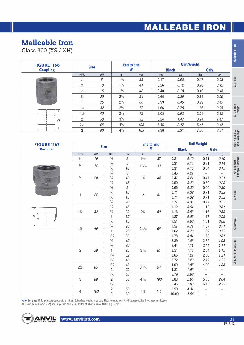
FIGURE 1166Coupling
Size End to EndW
Unit WeightBlack Galv.
NPS DN in mm lbs kg lbs kg1⁄4 8 13⁄8 35 0.17 0.08 0.17 0.083⁄8 10 15⁄8 41 0.26 0.12 0.26 0.121⁄2 15 17⁄8 48 0.40 0.18 0.40 0.183⁄4 20 21⁄8 54 0.65 0.29 0.65 0.29
1 25 23⁄8 60 0.99 0.45 0.99 0.45
11⁄4 32 27⁄8 73 1.66 0.75 1.66 0.75
11⁄2 40 27⁄8 73 2.03 0.92 2.03 0.92
2 50 35⁄8 92 3.24 1.47 3.24 1.47
21⁄2 65 41⁄8 105 5.45 2.47 5.45 2.47
3 80 41⁄8 105 7.30 3.31 7.30 3.31
Malleable Iron Class 300 (XS / XH)
FIGURE 1167 Reducer
Size End to EndM
Unit WeightBlack Galv.
NPS DN NPS DN in mm lbs kg lbs kg3⁄8 10 1⁄4 8 17⁄16 37 0.21 0.10 0.21 0.10
1⁄2 151⁄4 8
111⁄16 430.31 0.14 0.31 0.14
3⁄8 10 0.34 0.15 0.34 0.15
3⁄4 20
1⁄4 813⁄4 44
0.46 0.21 – –3⁄8 10 0.47 0.21 0.47 0.211⁄2 15 0.50 0.23 0.50 0.23
1 25
1⁄4 8
2 51
0.66 0.30 0.66 0.303⁄8 10 0.71 0.32 0.71 0.321⁄2 15 0.71 0.32 0.71 0.323⁄4 20 0.77 0.35 0.77 0.35
11⁄4 32
1⁄2 1523⁄8 60
1.12 0.51 1.12 0.513⁄4 20 1.16 0.53 1.16 0.531 25 1.27 0.58 1.27 0.58
11⁄2 40
1⁄2 15
211⁄16 68
1.51 0.68 1.51 0.683⁄4 20 1.57 0.71 1.57 0.711 25 1.62 0.73 1.62 0.73
11⁄4 32 1.78 0.81 1.78 0.81
2 50
1⁄2 15
33⁄16 81
2.39 1.08 2.39 1.083⁄4 20 2.44 1.11 2.44 1.111 25 2.54 1.15 2.54 1.15
11⁄4 32 2.66 1.21 2.66 1.2111⁄2 40 2.72 1.23 2.72 1.23
21⁄2 6511⁄2 40
311⁄16 944.09 1.85 4.09 1.85
2 50 4.32 1.96 – –
3 8011⁄2 40
41⁄16 1035.79 2.63 – –
2 50 5.83 2.64 5.83 2.6421⁄2 65 6.45 2.93 6.45 2.93
4 1002 50
43⁄8 1119.50 4.31 – –
3 80 10.00 4.54 – –
W
M
PF-6.13
MALLEABLE IRON
Note:/8
www.anvilintl.com32
Malleable Iron Class 300 (XS / XH)
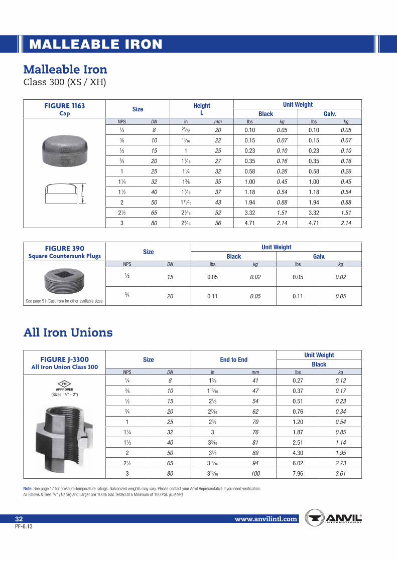
FIGURE 1163Cap
Size HeightL
Unit WeightBlack Galv.
NPS DN in mm lbs kg lbs kg1⁄4 8 25⁄32 20 0.10 0.05 0.10 0.053⁄8 10 13⁄16 22 0.15 0.07 0.15 0.071⁄2 15 1 25 0.23 0.10 0.23 0.103⁄4 20 11⁄16 27 0.35 0.16 0.35 0.16
1 25 11⁄4 32 0.58 0.26 0.58 0.26
11⁄4 32 13⁄8 35 1.00 0.45 1.00 0.45
11⁄2 40 17⁄16 37 1.18 0.54 1.18 0.54
2 50 111⁄16 43 1.94 0.88 1.94 0.88
21⁄2 65 21⁄16 52 3.32 1.51 3.32 1.51
3 80 23⁄16 56 4.71 2.14 4.71 2.14
FIGURE 390Square Countersunk Plugs
SizeUnit Weight
Black Galv.NPS DN lbs kg lbs kg
1⁄2 15 0.05 0.02 0.05 0.02
3⁄4 20 0.11 0.05 0.11 0.05
FIGURE J-3300 All Iron Union Class 300
Size End to EndUnit Weight
BlackNPS DN in mm lbs kg
1⁄4 8 15⁄8 41 0.27 0.123⁄8 10 113⁄16 47 0.37 0.171⁄2 15 21⁄8 54 0.51 0.233⁄4 20 27⁄16 62 0.76 0.34
1 25 23⁄4 70 1.20 0.54
11⁄4 32 3 76 1.87 0.85
11⁄2 40 33⁄16 81 2.51 1.14
2 50 31⁄2 89 4.30 1.95
21⁄2 65 311⁄16 94 6.02 2.73
3 80 315⁄16 100 7.96 3.61
All Iron Unions
L
(Sizes: 1/4" - 2")
PF-6.13

MALLEABLE IRON
Mal
leab
le Ir
onCa
st Ir
onSm
all S
teel
Fi
tting
sPi
pe N
ippl
es &
Pipe
Cou
plin
gsFo
rged
Ste
elFi
tting
s &
Unio
nsAn
vile
tsCa
taw
issa
J.B.
Sm
ith P
rodu
cts
www.anvilintl.com 33
Malleable Iron UnionsClass 150; 250; 300
(UL Listed Sizes: 1/4" - 2")(FM Approved Sizes: 1/4" - 3")
Note: 3/4" x 1/2" size is not UL Listed or FM Approved.
(UL Listed Sizes: 1/4" - 2")(FM Approved Sizes: 1/4" - 4")
(UL Listed Sizes: 1/4" - 2")(FM Approved Sizes: 1/4" - 4")
BRONZE TO IRON
Unions Size End to EndUnit Weight
Black Galv.NPS DN in mm lbs kg lbs kg
FIGURE 463 Class 150 Union
150lb. wsp · 300lb. wog non-shock
1⁄8 6 15⁄16 33 0.15 0.07 0.15 0.071⁄4 8 113⁄16 47 0.48 0.22 0.48 0.223⁄8 10 113⁄16 47 0.42 0.19 0.42 0.191⁄2 15 115⁄16 49 0.42 0.19 0.42 0.193⁄4 20 21⁄16 52 0.60 0.27 0.60 0.27
3⁄4 x 1⁄2 20 x 15 21⁄16 52 0.55 0.25 0.55 0.251 25 27⁄16 62 1.12 0.51 1.12 0.51
11⁄4 32 25⁄8 67 1.74 0.79 1.74 0.7911⁄2 40 23⁄4 70 2.08 0.94 2.08 0.942 50 215⁄16 75 3.00 1.36 3.00 1.36
21⁄2 65 35⁄8 92 3.60 1.63 3.60 1.633 80 33⁄4 95 4.95 2.24 4.95 2.24
FIGURE 554 Class 250 Union
250 lb. wsp · 500lb. wog non-shock
1⁄8 6 15⁄16 33 0.14 0.06 – –1⁄4 8 113⁄16 47 0.48 0.22 0.48 0.223⁄8 10 113⁄16 47 0.42 0.19 0.42 0.191⁄2 15 21⁄16 52 0.64 0.29 0.64 0.293⁄4 20 21⁄4 57 1.00 0.45 1.00 0.451 25 29⁄16 65 1.56 0.71 1.56 0.71
11⁄4 32 23⁄4 70 2.30 1.04 2.30 1.0411⁄2 40 3 76 2.74 1.24 2.74 1.242 50 33⁄8 86 4.34 1.97 4.34 1.97
21⁄2 65 37⁄8 98 5.30 2.40 5.30 2.403 80 41⁄4 108 7.60 3.45 7.60 3.454 100 47⁄8 124 17.50 7.94 17.50 7.94
FIGURE 459 Class 300 Union
300lb. wsp · 600lb. wog non-shock
1⁄8 6 15⁄16 33 0.14 0.06 0.14 0.061⁄4 8 113⁄16 47 0.48 0.22 0.48 0.223⁄8 10 113⁄16 47 0.42 0.19 0.42 0.191⁄2 15 21⁄16 52 0.64 0.29 0.64 0.293⁄4 20 21⁄4 57 1.00 0.45 1.00 0.451 25 29⁄16 65 1.56 0.71 1.56 0.71
11⁄4 32 23⁄4 70 2.30 1.04 2.30 1.0411⁄2 40 3 76 2.74 1.24 2.74 1.242 50 33⁄8 86 4.34 1.97 4.34 1.97
21⁄2 65 37⁄8 98 5.05 2.29 5.05 2.293 80 41⁄4 108 7.66 3.47 7.66 3.474 100 47⁄8 124 17.70 8.03 17.70 8.03
FIGURE 551 Class 300 Union male & female300lb. wsp · 600lb. wog non-shock
1⁄2 15 3 76 0.62 0.28 – –
3⁄4 20 33⁄16 81 0.92 0.42 – –
1 25 35⁄8 92 1.54 0.70 – –
11⁄2 40 41⁄4 108 2.60 1.18 – –
2 50 45⁄8 117 4.21 1.91 – –
PF-11.13

MALLEABLE IRON
www.anvilintl.com34
Malleable Iron UnionsClass 150; 250; 300
BRONZE TO IRON
FIGURE 552 Class 300 90° Elbow
Female Union 300lb. wsp
SizeCenter to End Unit Weight
Elbow Union BlackNPS DN in mm in mm lbs kg
3⁄8 10 11⁄16 27 21⁄16 52 0.51 0.23
1⁄2 15 11⁄4 32 25⁄16 59 0.79 0.36
3⁄4 20 17⁄16 37 23⁄4 70 1.24 0.56
1 25 15⁄8 41 3 76 1.88 0.85
FIGURE 832 Dart Union Bronze to
Bronze Seat Union
Size A B C DUnit Weight
Black Galv.NPS DN in mm in mm in mm in mm lbs kg lbs kg
3⁄8 10 13⁄4 44 15⁄16 24 11⁄2 38 13⁄4 44 0.41 0.19 0.43 0.20
1⁄2 15 21⁄8 54 11⁄8 29 13⁄16 30 2 51 0.58 0.26 0.61 0.28
3⁄4 20 25⁄16 59 13⁄8 35 23⁄16 56 21⁄2 64 0.82 0.37 0.86 0.39
1 25 25⁄8 67 111⁄16 43 29⁄16 65 3 76 1.31 0.59 1.36 0.62
11⁄4 32 213⁄16 73 21⁄16 52 31⁄16 78 31⁄2 89 1.90 0.86 2.00 0.91
11⁄2 40 3 76 23⁄16 56 33⁄8 86 4 102 2.32 1.05 2.43 1.10
2 50 35⁄8 92 27⁄8 73 41⁄16 103 45⁄8 117 4.00 1.81 4.20 1.90
• Meets ASME B16.39 The standard union for most installations 3⁄8 – 2 NPS (10 – 50 DN) – 300lb (136 kg) steam working pressure at 450°F. 3⁄8 – 2 NPS (10 – 50 DN) – 600lb (272 kg) cold water, gas, or oil pressure - non-shock.
• Bronze Seat, on both sides of the joint. Resists corrosion.• True bearing surfaces, unlike ordinary union seats.• Bodies and nuts are high test air-refined malleable iron - generally superior to mild steel in most services.• Can be repeatedly installed and removed.• Straight way through. No cored parts to hold liquid or sediment.• Extra heavy shoulder on swivel end and in the nut to stand pipe strains, vibration, and wrench abuse.• Bronze Seat Ball Joint, with extra wide seating surfaces.
DART A
BC on FlatD on Flat
PF-11.13

MALLEABLE IRON
Mal
leab
le Ir
onCa
st Ir
onSm
all S
teel
Fi
tting
sPi
pe N
ippl
es &
Pipe
Cou
plin
gsFo
rged
Ste
elFi
tting
s &
Unio
nsAn
vile
tsCa
taw
issa
J.B.
Sm
ith P
rodu
cts
www.anvilintl.com 35
Malleable Hex and Face Bushing
FIGURE 383Hex Bushing
SizeUnit Weight
Black Galv.NPS DN Hex Type NPS DN lbs kg lbs kg
3⁄4 10
A 1⁄8 6 0.12 0.05 0.12 0.05
A 1⁄4 8 0.14 0.06 0.14 0.06
A 3⁄8 10 0.11 0.05 0.11 0.05
A 1⁄2 15 0.09 0.04 0.09 0.04
1 25
B 1⁄8 6 0.24 0.11 0.24 0.11
B 1⁄4 8 0.18 0.08 0.18 0.08
B 3⁄8 10 0.18 0.08 0.18 0.08
A 1⁄2 15 0.20 0.09 0.20 0.09
A 3⁄4 20 0.16 0.07 0.16 0.07
11⁄4 32
B 1⁄4 8 0.33 0.15 0.33 0.15
B 3⁄8 10 0.27 0.12 0.27 0.12
B 1⁄2 15 0.34 0.15 0.34 0.15
A 3⁄4 20 0.39 0.18 0.39 0.18
A 1 25 0.30 0.14 0.30 0.14
11⁄2 40 A 11⁄4 32 0.30 0.14 0.30 0.14
2 50 A 11⁄2 40 0.64 0.29 0.64 0.29
21⁄2 65 A 2 50 1.02 0.46 1.02 0.46
FIGURE 385Face Bushing
SizeUnit Weight
Black Galv.NPS DN NPS DN lbs kg lbs kg
3⁄4 203⁄8 10 0.08 0.04 – –1⁄2 15 0.06 0.03 0.06 0.03
1 251⁄2 15 0.16 0.07 0.16 0.073⁄4 20 0.10 0.05 0.10 0.05
11⁄4 32
1⁄2 15 0.30 0.14 – –3⁄4 20 0.27 0.12 – –
1 25 0.19 0.09 0.19 0.09
11⁄2 40
1⁄2 15 0.40 0.18 – –3⁄4 20 0.39 0.18 – –
1 25 0.33 0.15 – –
11⁄4 32 0.16 0.07 0.16 0.07
2 50
1 25 0.65 0.29 0.65 0.29
11⁄4 32 0.53 0.24 0.53 0.24
11⁄2 40 0.40 0.18 0.40 0.18
21⁄2 65
11⁄4 32 1.10 0.50 – –
11⁄2 40 0.93 0.42 – –
2 50 0.40 0.18 0.40 0.18
3 80 21⁄2 65 0.99 0.45 – –
Note: ⁄⁄
PF-6.13
Outside HexType A
Inside HexType B
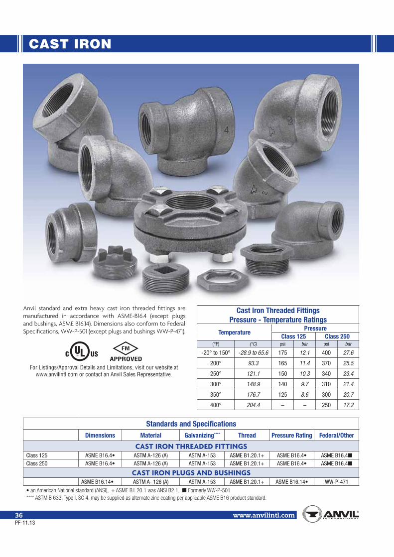
CAST IRON
Note:
www.anvilintl.com36PF-11.13
For Listings/Approval Details and Limitations, visit our website at www.anvilintl.com or contact an Anvil Sales Representative.
Standards and SpecificationsDimensions Material Galvanizing**** Thread Pressure Rating Federal/Other
CAST IRON THREADED FITTINGSClass 125 ASTM A-126 (A) ASTM A-153 ASME B1.20.1+ ASME B16.4Class 250 ASTM A-126 (A) ASTM A-153 ASME B1.20.1+ ASME B16.4
CAST IRON PLUGS AND BUSHINGSASTM A- 126 (A) ASTM A-153 ASME B1.20.1+ WW-P-471
Anvil standard and extra heavy cast iron threaded fittings are manufactured in accordance with ASME-B16.4 (except plugs and bushings, ASME B16.14). Dimensions also conform to Federal Specifications, WW-P-501 (except plugs and bushings WW-P-471).
Cast Iron Threaded FittingsPressure - Temperature Ratings
TemperaturePressure
Class 125 Class 250(°F) (°C) psi bar psi bar
-20° to 150° -28.9 to 65.6 175 12.1 400 27.6
200° 93.3 165 11.4 370 25.5
250° 121.1 150 10.3 340 23.4
300° 148.9 140 9.7 310 21.4
350° 176.7 125 8.6 300 20.7
400° 204.4 – – 250 17.2
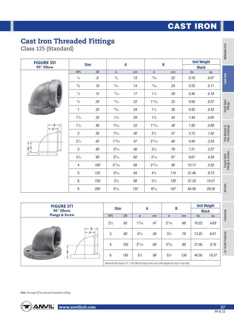
CAST IRON
Mal
leab
le Ir
onCa
st Ir
onSm
all S
teel
Fi
tting
sPi
pe N
ippl
es &
Pipe
Cou
plin
gsFo
rged
Ste
elFi
tting
s &
Unio
nsAn
vile
tsCa
taw
issa
J.B.
Sm
ith P
rodu
cts
Note:
www.anvilintl.com 37
FIGURE 35190˚ Elbow
Size A BUnit Weight
BlackNPS DN in mm in mm lbs kg
1/4 8 1/2 13 13/16 22 0.16 0.07
3/8 10 9/16 14 15/16 24 0.25 0.11
1/2 15 11/16 17 11/8 29 0.40 0.18
3/4 20 13/16 22 115/16 33 0.60 0.27
1 25 15/16 24 11/2 38 0.92 0.42
11/4 32 11/8 29 13/4 44 1.44 0.65
11/2 40 15/16 33 115/16 49 1.95 0.88
2 50 19/16 40 21/4 57 3.13 1.42
21/2 65 113/16 47 211/16 68 4.94 2.24
3 80 23/16 56 31/8 79 7.21 3.27
31/2 90 27/16 62 37/16 87 9.67 4.39
4 100 211/16 68 313/16 98 12.17 5.52
5 125 35/16 84 41/2 114 21.46 9.73
6 150 37/8 98 51/8 130 31.33 14.21
8 200 53/16 132 69/16 167 64.56 29.28
Cast Iron Threaded Fittings Class 125 (Standard)
A
B A
B
FIGURE 37190˚ Elbow,
Flange & Screw
Size A BUnit Weight
BlackNPS DN in mm in mm lbs kg
21⁄2 65 113⁄16 47 211⁄16 68 10.22 4.63
3 80 23⁄16 56 31⁄8 79 13.25 6.01
4 100 211⁄16 68 313⁄16 98 21.56 9.78
6 150 37⁄8 98 51⁄8 130 40.50 18.37
(100 DN)
A
B
B
PF-6.13
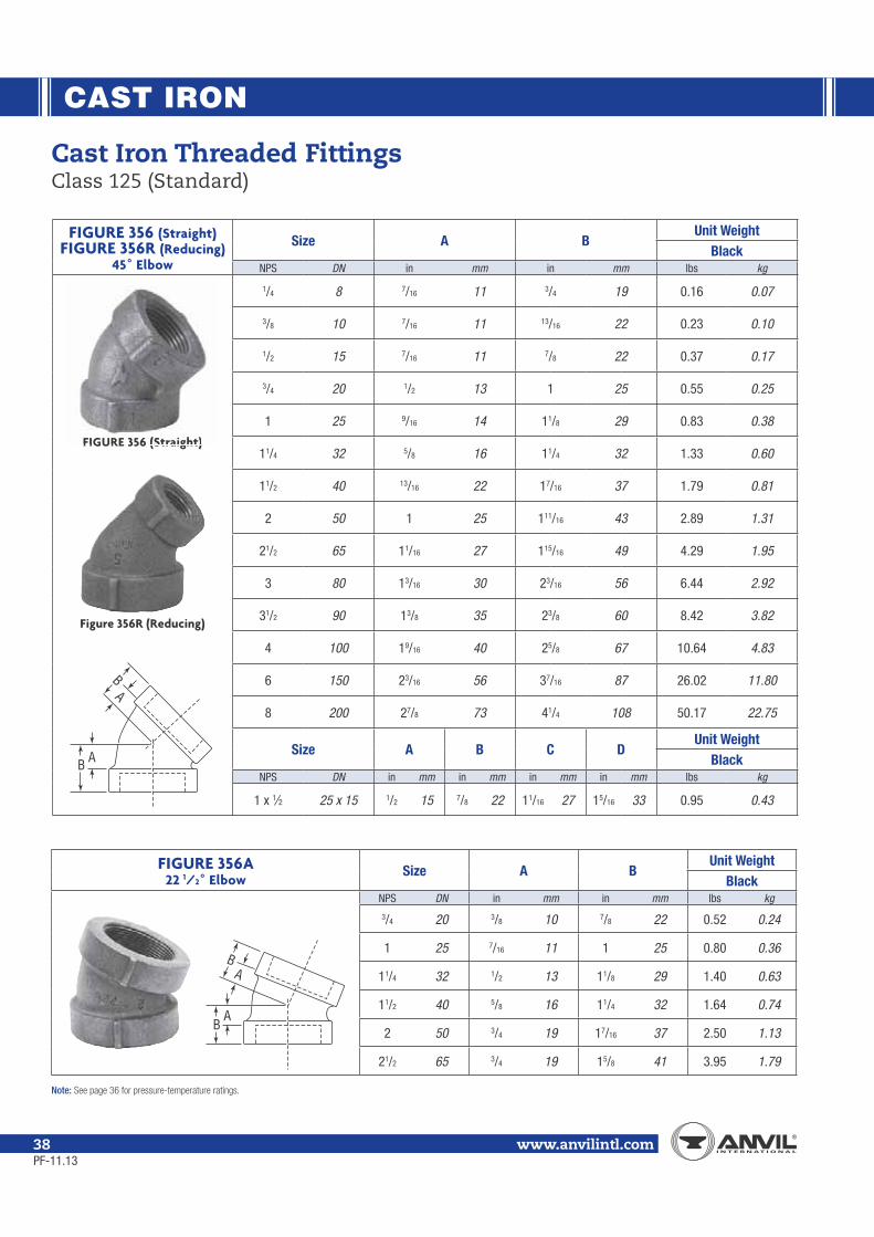
CAST IRON
Note:
www.anvilintl.com38
FIGURE 356 (Straight)FIGURE 356R (Reducing)
45˚ Elbow
Size A BUnit Weight
BlackNPS DN in mm in mm lbs kg
1/4 8 7/16 11 3/4 19 0.16 0.07
3/8 10 7/16 11 13/16 22 0.23 0.10
1/2 15 7/16 11 7/8 22 0.37 0.17
3/4 20 1/2 13 1 25 0.55 0.25
1 25 9/16 14 11/8 29 0.83 0.38
11/4 32 5/8 16 11/4 32 1.33 0.60
11/2 40 13/16 22 17/16 37 1.79 0.81
2 50 1 25 111/16 43 2.89 1.31
21/2 65 11/16 27 115/16 49 4.29 1.95
3 80 13/16 30 23/16 56 6.44 2.92
31/2 90 13/8 35 23/8 60 8.42 3.82
4 100 19/16 40 25/8 67 10.64 4.83
6 150 23/16 56 37/16 87 26.02 11.80
8 200 27/8 73 41/4 108 50.17 22.75
Size A B C DUnit Weight
BlackNPS DN in mm in mm in mm in mm lbs kg
1 x 1⁄2 25 x 15 1/2 15 7/8 22 11/16 27 15/16 33 0.95 0.43
Cast Iron Threaded Fittings Class 125 (Standard)
FIGURE 356A22 1/2˚ Elbow
Size A BUnit Weight
BlackNPS DN in mm in mm lbs kg
3/4 20 3/8 10 7/8 22 0.52 0.24
1 25 7/16 11 1 25 0.80 0.36
11/4 32 1/2 13 11/8 29 1.40 0.63
11/2 40 5/8 16 11/4 32 1.64 0.74
2 50 3/4 19 17/16 37 2.50 1.13
21/2 65 3/4 19 15/8 41 3.95 1.79
B A
BA
BA
BA
FIGURE 356 (Straight)
Figure 356R (Reducing)
PF-11.13
FIGURE 356 (Straight)
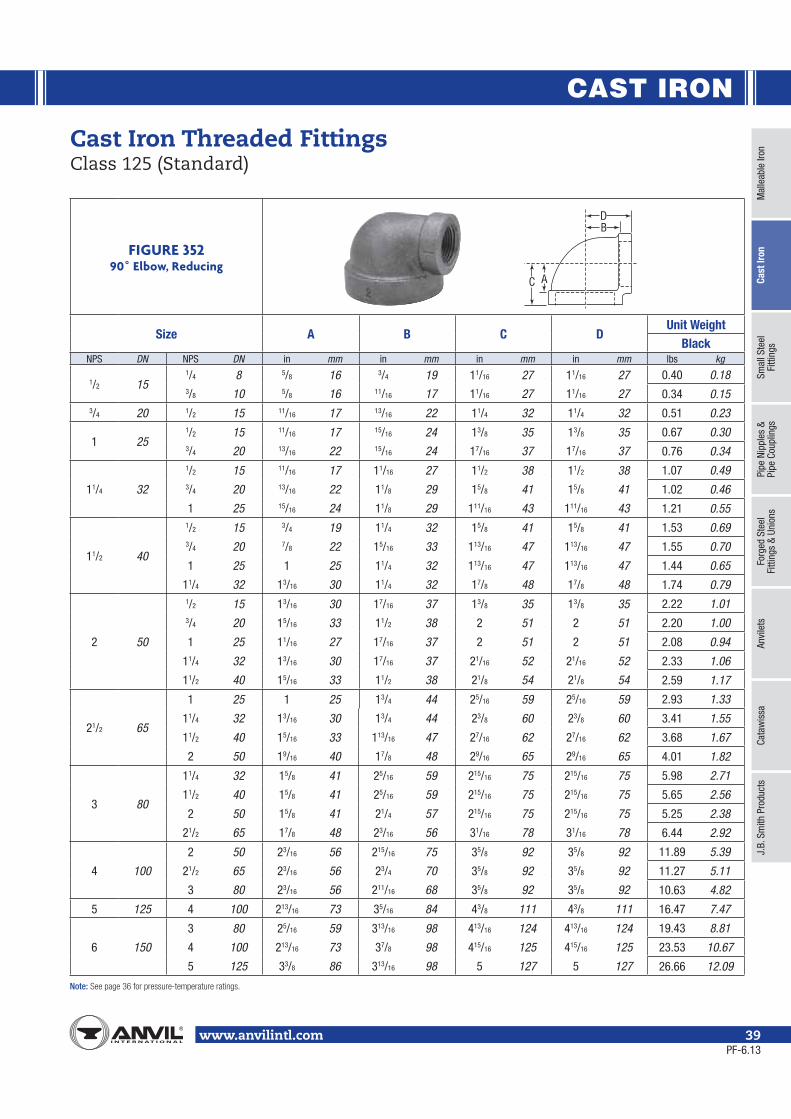
CAST IRON
Mal
leab
le Ir
onCa
st Ir
onSm
all S
teel
Fi
tting
sPi
pe N
ippl
es &
Pipe
Cou
plin
gsFo
rged
Ste
elFi
tting
s &
Unio
nsAn
vile
tsCa
taw
issa
J.B.
Sm
ith P
rodu
cts
Note:
www.anvilintl.com 39
FIGURE 35290˚ Elbow, Reducing
Size A B C DUnit Weight
BlackNPS DN NPS DN in mm in mm in mm in mm lbs kg
1/2 151/4 8 5/8 16 3/4 19 11/16 27 11/16 27 0.40 0.183/8 10 5/8 16 11/16 17 11/16 27 11/16 27 0.34 0.15
3/4 20 1/2 15 11/16 17 13/16 22 11/4 32 11/4 32 0.51 0.23
1 251/2 15 11/16 17 15/16 24 13/8 35 13/8 35 0.67 0.303/4 20 13/16 22 15/16 24 17/16 37 17/16 37 0.76 0.34
11/4 32
1/2 15 11/16 17 11/16 27 11/2 38 11/2 38 1.07 0.493/4 20 13/16 22 11/8 29 15/8 41 15/8 41 1.02 0.46
1 25 15/16 24 11/8 29 111/16 43 111/16 43 1.21 0.55
11/2 40
1/2 15 3/4 19 11/4 32 15/8 41 15/8 41 1.53 0.693/4 20 7/8 22 15/16 33 113/16 47 113/16 47 1.55 0.70
1 25 1 25 11/4 32 113/16 47 113/16 47 1.44 0.65
11/4 32 13/16 30 11/4 32 17/8 48 17/8 48 1.74 0.79
2 50
1/2 15 13/16 30 17/16 37 13/8 35 13/8 35 2.22 1.013/4 20 15/16 33 11/2 38 2 51 2 51 2.20 1.00
1 25 11/16 27 17/16 37 2 51 2 51 2.08 0.94
11/4 32 13/16 30 17/16 37 21/16 52 21/16 52 2.33 1.06
11/2 40 15/16 33 11/2 38 21/8 54 21/8 54 2.59 1.17
21/2 65
1 25 1 25 13/4 44 25/16 59 25/16 59 2.93 1.33
11/4 32 13/16 30 13/4 44 23/8 60 23/8 60 3.41 1.55
11/2 40 15/16 33 113/16 47 27/16 62 27/16 62 3.68 1.67
2 50 19/16 40 17/8 48 29/16 65 29/16 65 4.01 1.82
3 80
11/4 32 15/8 41 25/16 59 215/16 75 215/16 75 5.98 2.71
11/2 40 15/8 41 25/16 59 215/16 75 215/16 75 5.65 2.56
2 50 15/8 41 21/4 57 215/16 75 215/16 75 5.25 2.38
21/2 65 17/8 48 23/16 56 31/16 78 31/16 78 6.44 2.92
4 100
2 50 23/16 56 215/16 75 35/8 92 35/8 92 11.89 5.39
21/2 65 23/16 56 23/4 70 35/8 92 35/8 92 11.27 5.11
3 80 23/16 56 211/16 68 35/8 92 35/8 92 10.63 4.82
5 125 4 100 213/16 73 35/16 84 43/8 111 43/8 111 16.47 7.47
6 150
3 80 25/16 59 313/16 98 413/16 124 413/16 124 19.43 8.81
4 100 213/16 73 37/8 98 415/16 125 415/16 125 23.53 10.67
5 125 33/8 86 313/16 98 5 127 5 127 26.66 12.09
Cast Iron Threaded Fittings Class 125 (Standard)
B
C
D
A
PF-6.13

CAST IRON
Note:
www.anvilintl.com40
FIGURE 359Tee Reducing
Size A B C D E FUnit Weight
Black
NPS DN NPS DN NPS DN in mm in mm in mm in mm in mm in mm lbs kg
1/2 15 1/2 15
1/4 8 11/16 17 11/16 17 13/16 22 11/8 29 11/8 29 11/8 29 0.57 0.263/8 10 11/16 17 11/16 17 3/4 19 11/8 29 11/8 29 11/8 29 0.57 0.263/4 20 13/16 22 13/16 22 11/16 17 11/4 32 11/4 32 13/16 22 0.68 0.311 25 1 25 1 25 13/16 22 17/16 37 17/16 37 13/8 35 1.00 0.45
3/4 20
1/4 8 3/4 20 13/16 22 15/16 24 13/16 22 15/16 24 11/4 32 15/16 24 0.79 0.361/2 15
1/2 15 11/16 17 11/16 17 13/16 22 13/16 22 11/8 29 11/4 32 0.64 0.293/4 20 13/16 22 13/16 22 13/16 22 15/16 24 11/4 32 15/16 24 0.75 0.34
3/4 20
1/4 8 9/16 14 9/16 14 7/8 22 11/16 17 11/16 17 13/16 22 0.62 0.283/8 10 11/16 17 11/16 17 15/16 24 13/16 22 13/16 22 11/4 32 0.75 0.341/2 15 11/16 17 11/16 17 13/16 22 13/16 22 13/16 22 11/4 32 0.76 0.341 25 15/16 24 15/16 24 13/16 22 17/16 37 17/16 37 13/8 35 0.99 0.45
1 25
1/4 8 1 25 15/16 24 15/16 24 15/16 24 11/2 38 11/4 32 11/2 38 1.08 0.49
1/2 15
1/2 15 11/16 17 3/4 19 15/16 24 11/4 32 13/16 22 13/8 35 0.90 0.413/4 20 13/16 22 13/16 22 15/16 24 13/8 35 11/4 32 17/16 37 0.91 0.411 25 15/16 24 15/16 24 15/16 24 11/2 38 13/8 35 11/2 38 1.08 0.49
3/4 20
1/2 15 11/16 17 11/16 17 15/16 24 11/4 32 13/16 22 13/8 35 0.89 0.403/4 20 13/16 22 13/16 22 15/16 24 13/8 35 15/16 24 17/16 37 1.00 0.451 25 15/16 24 15/16 24 15/16 24 11/2 38 17/16 37 11/2 38 1.13 0.51
1 25
1/4 8 11/16 17 11/16 17 11/8 29 11/8 29 11/4 32 13/8 35 1.01 0.461/2 15 11/16 17 11/16 17 15/16 24 11/4 32 11/4 32 13/8 35 1.01 0.463/4 20 13/16 22 13/16 22 15/16 24 13/8 35 13/8 35 17/16 37 1.11 0.50
11/4 32 11/8 29 11/8 29 15/16 24 111/16 43 111/16 43 19/16 40 1.49 0.6811/2 40 11/4 32 11/4 32 1 25 113/16 47 113/16 47 15/8 41 1.84 0.832 50 17/16 37 17/16 37 1 25 2 50 2 50 13/4 44 2.70 1.22
FIGURE 358Tee
Size A BUnit Weight
BlackNPS DN in mm in mm lbs kg1/4 8 1/2 13 13/16 22 0.22 0.103/8 10 5/8 16 1 25 0.35 0.161/2 15 11/16 17 11/8 29 0.56 0.253/4 20 13/16 22 15/16 33 0.84 0.381 25 15/16 24 11/2 38 1.25 0.57
11/4 32 11/8 29 13/4 44 2.03 0.9211/2 40 15/16 33 115/16 49 2.70 1.222 50 19/16 40 21/4 57 4.23 1.92
21/2 65 113/16 47 211/16 68 6.67 3.023 80 23/16 56 31/8 79 10.00 4.54
31/2 90 27/16 62 37/16 87 13.29 6.034 100 211/16 68 33/4 95 16.33 7.415 125 35/16 84 41/2 114 27.33 12.396 150 37/8 98 51/8 130 40.85 18.538 200 53/16 132 69/16 167 79.00 35.83
Cast Iron Threaded Fittings Class 125 (Standard)
Continued on next page.
B
A
A B
B
A
E
B
C F
D
A
PF-11.13
Tee
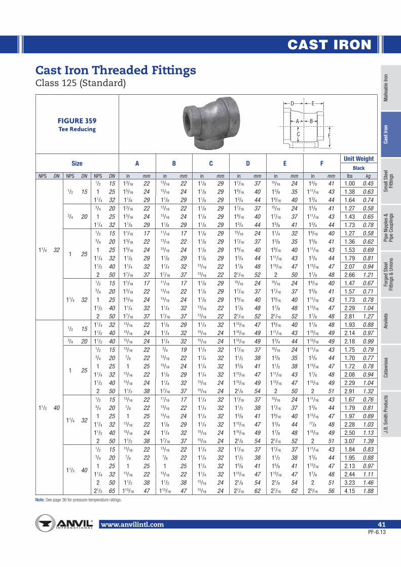
CAST IRON
Mal
leab
le Ir
onCa
st Ir
onSm
all S
teel
Fi
tting
sPi
pe N
ippl
es &
Pipe
Cou
plin
gsFo
rged
Ste
elFi
tting
s &
Unio
nsAn
vile
tsCa
taw
issa
J.B.
Sm
ith P
rodu
cts
Note:
www.anvilintl.com 41
Cast Iron Threaded Fittings Class 125 (Standard)
FIGURE 359Tee Reducing
Size A B C D E FUnit Weight
Black
NPS DN NPS DN NPS DN in mm in mm in mm in mm in mm in mm lbs kg
11/4 32
1/2 15
1/2 15 13/16 22 13/16 22 11/8 29 17/16 37 15/16 24 15/8 41 1.00 0.451 25 15/16 24 15/16 24 11/8 29 19/16 40 13/8 35 111/16 43 1.38 0.63
11/4 32 11/8 29 11/8 29 11/8 29 13/4 44 19/16 40 13/4 44 1.64 0.74
3/4 20
3/4 20 13/16 22 13/16 22 11/8 29 17/16 37 15/16 24 15/8 41 1.27 0.581 25 15/16 24 15/16 24 11/8 29 19/16 40 17/16 37 111/16 43 1.43 0.65
11/4 32 11/8 29 11/8 29 11/8 29 13/4 44 15/8 41 13/4 44 1.73 0.78
1 25
1/2 15 11/16 17 11/16 17 11/8 29 15/16 24 11/4 32 19/16 40 1.27 0.583/4 20 13/16 22 13/16 22 11/8 29 17/16 37 13/8 35 15/8 41 1.36 0.621 25 15/16 24 15/16 24 11/8 29 19/16 40 19/16 40 111/16 43 1.53 0.69
11/4 32 11/8 29 11/8 29 11/8 29 13/4 44 111/16 43 13/4 44 1.79 0.8111/2 40 11/4 32 11/4 32 13/16 22 17/8 48 113/16 47 113/16 47 2.07 0.942 50 17/16 37 17/16 37 13/16 22 21/16 52 2 50 17/8 48 2.66 1.21
11/4 32
1/2 15 11/16 17 11/16 17 11/8 29 15/16 24 15/16 24 19/16 40 1.47 0.673/4 20 13/16 22 13/16 22 11/8 29 17/16 37 17/16 37 15/8 41 1.57 0.711 25 15/16 24 15/16 24 11/8 29 19/16 40 19/16 40 111/16 43 1.73 0.78
11/2 40 11/4 32 11/4 32 13/16 22 17/8 48 17/8 48 113/16 47 2.29 1.042 50 17/16 37 17/16 37 13/16 22 21/16 52 21/16 52 17/8 48 2.81 1.27
11/2 40
1/2 1511/4 32 13/16 22 11/8 29 11/4 32 113/16 47 19/16 40 17/8 48 1.93 0.8811/2 40 15/16 24 11/4 32 15/16 24 115/16 49 111/16 43 115/16 49 2.14 0.97
3/4 20 11/2 40 15/16 24 11/4 32 15/16 24 115/16 49 13/4 44 115/16 49 2.18 0.99
1 25
1/2 15 13/16 22 3/4 19 11/4 32 17/16 37 15/16 24 111/16 43 1.75 0.793/4 20 7/8 22 13/16 22 11/4 32 11/2 38 13/8 35 13/4 44 1.70 0.771 25 1 25 15/16 24 11/4 32 15/8 41 11/2 38 113/16 47 1.72 0.78
11/4 32 13/16 22 11/8 29 11/4 32 113/16 47 111/16 43 17/8 48 2.08 0.9411/2 40 15/16 24 11/4 32 15/16 24 115/16 49 113/16 47 115/16 49 2.29 1.042 50 11/2 38 17/16 37 15/16 24 21/8 54 2 50 2 51 2.91 1.32
11/4 32
1/2 15 13/16 22 11/16 17 11/4 32 17/16 37 15/16 24 111/16 43 1.67 0.763/4 20 7/8 22 13/16 22 11/4 32 11/2 38 17/16 37 13/4 44 1.79 0.811 25 1 25 15/16 24 11/4 32 15/8 41 19/16 40 113/16 47 1.97 0.89
11/4 32 13/16 22 11/8 29 11/4 32 113/16 47 13/4 44 17/8 48 2.28 1.0311/2 40 15/16 24 11/4 32 15/16 24 115/16 49 17/8 48 115/16 49 2.50 1.132 50 11/2 38 17/16 37 15/16 24 21/8 54 21/16 52 2 51 3.07 1.39
11/2 40
1/2 15 13/16 22 13/16 22 11/4 32 17/16 37 17/16 37 111/16 43 1.84 0.833/4 20 7/8 22 7/8 22 11/4 32 11/2 38 11/2 38 13/4 44 1.95 0.881 25 1 25 1 25 11/4 32 15/8 41 15/8 41 113/16 47 2.13 0.97
11/4 32 13/16 22 13/16 22 11/4 32 113/16 47 113/16 47 17/8 48 2.44 1.112 50 11/2 38 11/2 38 15/16 24 21/8 54 21/8 54 2 51 3.23 1.46
21/2 65 113/16 47 113/16 47 15/16 24 27/16 62 27/16 62 23/16 56 4.15 1.88
E
B
C F
D
A
PF-6.13

CAST IRON
Note:
www.anvilintl.com42
Cast Iron Threaded Fittings Class 125 (Standard)
FIGURE 359Tee Reducing
Size A B C D E FUnit Weight
Black
NPS DN NPS DN NPS DN in mm in mm in mm in mm in mm in mm lbs kg
2 50
1/2 1511/2 40 15/16 24 13/8 35 11/2 38 2 51 113/16 47 21/8 54 2.95 1.342 50 19/16 40 17/16 37 19/16 40 21/4 57 17/8 48 21/4 57 3.30 1.50
3/4 2011/4 32 13/16 22 11/8 29 17/16 37 17/8 48 13/4 44 21/16 52 2.50 1.1311/2 40 15/16 24 15/16 24 11/2 38 2 51 113/16 47 21/8 54 3.40 1.542 50 19/16 40 17/16 37 19/16 40 21/4 57 115/16 49 21/4 57 3.31 1.50
1 25
1 25 11/16 17 11/16 17 17/16 37 13/4 44 15/8 41 2 51 2.70 1.2211/4 32 13/16 22 11/8 29 11/2 38 17/8 48 13/4 44 21/16 52 2.94 1.3311/2 40 15/16 24 11/4 32 11/2 38 2 51 113/16 47 21/8 54 2.85 1.292 50 19/16 40 17/16 37 19/16 40 21/4 57 2 51 21/4 57 3.46 1.57
21/2 65 17/8 48 113/16 47 19/16 40 29/16 65 23/8 60 27/16 62 4.88 2.21
11/4 32
1/2 15 11/16 17 1 25 17/16 37 13/4 44 15/8 41 2 51 2.48 1.123/4 20 7/8 22 7/8 22 17/16 37 19/16 40 11/2 38 115/16 49 2.50 1.131 25 11/16 17 1 25 17/16 37 13/4 44 15/8 41 2 51 2.73 1.24
11/4 32 13/16 22 11/8 29 17/16 37 17/8 48 13/4 44 21/16 52 2.90 1.3211/2 40 15/16 24 11/4 32 11/2 38 2 51 17/8 48 21/8 54 3.13 1.422 50 19/16 40 17/16 37 19/16 40 21/4 57 21/16 52 21/4 57 3.71 1.68
21/2 65 17/8 48 13/4 44 19/16 40 29/16 65 23/8 60 27/16 62 4.54 2.06
11/2 40
1/2 15 13/16 22 13/16 22 17/16 37 11/2 38 17/16 37 17/8 48 2.34 1.063/4 20 7/8 22 7/8 22 17/16 37 19/16 40 11/2 38 115/16 49 2.46 1.121 25 11/16 17 1 25 17/16 37 13/4 44 15/8 41 2 51 2.66 1.21
11/4 32 13/16 22 13/16 22 17/16 37 17/8 48 113/16 47 21/16 52 2.98 1.3511/2 40 15/16 24 15/16 24 11/2 38 2 51 115/16 49 21/8 54 3.24 1.472 50 19/16 40 11/2 38 19/16 40 21/4 57 21/8 54 21/4 57 3.70 1.68
21/2 65 17/8 48 115/16 49 19/16 40 29/16 65 29/16 65 27/16 62 5.46 2.48
2 50
1/2 15 13/16 22 13/16 22 17/16 37 11/2 38 11/2 38 17/8 48 2.74 1.243/4 20 7/8 22 7/8 22 17/16 37 19/16 40 19/16 40 115/16 49 2.86 1.301 25 11/16 17 11/16 17 17/16 37 13/4 44 13/4 44 2 51 3.05 1.38
11/4 32 13/16 22 13/16 22 17/16 37 17/8 48 17/8 48 21/16 52 3.38 1.5311/2 40 15/16 24 15/16 24 11/2 38 2 51 2 51 21/8 54 3.59 1.6321/2 65 17/8 48 17/8 48 19/16 40 29/16 65 29/16 65 27/16 62 5.17 2.343 100 3 76 3 76 27/16 62 311/16 94 311/16 94 31/2 89 7.87 3.57
Continued on next page.
E
B
C F
D
A
PF-6.13

CAST IRON
Mal
leab
le Ir
onCa
st Ir
onSm
all S
teel
Fi
tting
sPi
pe N
ippl
es &
Pipe
Cou
plin
gsFo
rged
Ste
elFi
tting
s &
Unio
nsAn
vile
tsCa
taw
issa
J.B.
Sm
ith P
rodu
cts
Note:
www.anvilintl.com 43
Cast Iron Threaded Fittings Class 125 (Standard)
FIGURE 359Tee Reducing
Size A B C D E FUnit Weight
Black
NPS DN NPS DN NPS DN in mm in mm in mm in mm in mm in mm lbs kg
21/2 65
1/2 15 21/2 65 113/16 47 113/16 47 113/16 47 211/16 68 21/4 57 211/16 68 5.20 2.363/4 20 21/2 65 113/16 47 13/4 44 113/16 47 211/16 68 21/4 57 211/16 68 5.10 2.31
1 25 2 50 19/16 40 19/16 40 17/8 48 27/16 62 21/8 54 29/16 65 5.03 2.2821/2 65 113/16 47 13/4 44 113/16 47 211/16 68 25/16 59 211/16 68 5.36 2.43
11/4 32 2 50 19/16 40 11/2 38 17/8 48 27/16 62 21/8 54 29/16 65 4.96 2.2521/2 65 113/16 47 13/4 44 113/16 47 211/16 68 23/8 60 211/16 68 5.40 2.45
11/2 4011/2 40 15/16 24 15/16 22 113/16 47 23/16 56 115/16 49 27/16 62 4.23 1.922 50 19/16 40 11/2 38 17/8 48 27/16 62 21/8 54 29/16 65 4.85 2.20
21/2 65 113/16 47 113/16 47 113/16 47 211/16 68 27/16 62 211/16 68 4.85 2.20
2 50
1/2 15 3/4 19 13/16 22 13/4 44 111/16 43 11/2 38 23/16 56 5.82 2.643/4 20 7/8 22 7/8 22 13/4 44 13/4 44 19/16 40 21/4 57 3.62 1.641 25 1 25 11/16 17 13/4 44 115/16 49 13/4 44 25/16 59 3.92 1.78
11/4 32 13/16 22 13/16 22 13/4 44 21/16 52 17/8 48 23/8 60 4.26 1.9311/2 40 15/16 24 15/16 24 113/16 47 23/16 56 2 51 27/16 62 4.42 2.002 50 19/16 40 19/16 40 17/8 48 27/16 62 21/4 57 29/16 65 5.17 2.34
21/2 65 113/16 47 17/8 48 113/16 47 211/16 68 29/16 65 211/16 68 6.00 2.723 80 21/16 52 21/8 54 17/8 48 3 80 27/8 73 213/16 73 7.35 3.33
21/2 65
1/2 15 3/4 19 3/4 19 13/4 44 111/16 43 111/16 43 23/16 56 4.00 1.813/4 20 7/8 22 7/8 22 13/4 44 13/4 44 13/4 44 21/4 57 4.29 1.951 25 1 25 1 25 13/4 44 115/16 49 115/16 49 25/16 59 4.48 2.03
11/4 32 13/16 22 13/16 22 13/4 44 21/16 52 21/16 52 23/8 60 4.83 2.1911/2 40 15/16 24 15/16 24 113/16 47 23/16 56 23/16 56 27/16 62 5.14 2.332 50 19/16 40 19/16 40 17/8 48 27/16 62 27/16 62 29/16 65 5.88 2.673 80 21/16 52 21/16 52 17/8 48 3 80 3 80 213/16 73 8.09 3.674 100 23/4 70 213/16 73 27/16 62 311/16 94 311/16 94 31/2 89 14.03 6.36
3 80
3/4 20 3 80 21/8 54 21/8 54 21/8 54 31/8 79 211/16 68 31/8 79 8.25 3.741 25 3 80 21/8 54 21/8 54 21/8 54 31/8 79 211/16 68 31/8 79 8.30 3.76
11/4 32 3 80 21/8 54 21/8 54 21/8 54 31/8 79 213/16 73 31/8 79 8.46 3.8411/2 40 3 80 21/8 54 23/16 56 21/8 54 31/8 79 213/16 73 31/8 79 8.13 3.69
2 50
11/2 40 13/8 35 11/2 38 23/16 56 25/16 59 23/16 56 213/16 73 6.83 3.102 50 19/16 40 19/16 40 23/16 56 29/16 65 21/4 57 215/16 75 7.29 3.31
21/2 65 17/8 48 115/16 49 21/8 54 213/16 73 29/16 65 31/16 78 7.10 3.223 80 21/8 54 23/16 56 21/8 54 31/8 79 215/16 75 31/8 79 8.79 3.99
21/2 65
1 25 1 25 15/16 24 21/8 54 21/16 52 115/16 49 211/16 68 5.51 2.5011/4 32 11/4 32 13/16 22 21/8 54 23/16 56 21/16 52 23/4 70 5.92 2.6811/2 40 13/8 35 15/16 24 23/16 56 25/16 59 23/16 56 213/16 73 6.23 2.832 50 19/16 40 11/2 38 23/16 56 29/16 65 27/16 62 215/16 75 6.81 3.09
21/2 65 17/8 48 113/16 47 21/8 54 213/16 73 211/16 68 31/16 78 7.66 3.473 80 21/8 54 21/8 54 21/8 54 31/8 79 31/16 78 31/8 79 9.13 4.14
3 80
1/2 15 15/16 24 15/16 24 23/16 56 17/8 48 17/8 48 25/8 67 6.08 2.763/4 20 15/16 24 15/16 24 21/8 54 17/8 48 17/8 48 25/8 67 6.06 2.751 25 1 25 1 25 21/8 54 21/16 52 21/16 52 211/16 68 6.27 2.84
11/4 32 11/4 32 11/4 32 21/8 54 23/16 56 23/16 56 23/4 70 6.75 3.0611/2 40 13/8 35 13/8 35 23/16 56 25/16 59 25/16 59 215/16 75 7.10 3.222 50 19/16 40 19/16 40 23/16 56 29/16 65 29/16 65 27/8 73 7.75 3.51
21/2 65 17/8 48 17/8 48 21/8 54 213/16 73 213/16 73 31/16 78 8.92 4.054 100 211/16 68 211/16 68 27/16 62 311/16 94 311/16 94 31/2 89 12.80 5.80
E
B
C F
D
A
PF-6.13

CAST IRON
Note:
www.anvilintl.com44
Cast Iron Threaded Fittings Class 125 (Standard)
FIGURE 359Tee Reducing
Size A B C D E FUnit Weight
Black
NPS DN NPS DN NPS DN in mm in mm in mm in mm in mm in mm lbs kg
31/2 90 31/2 9011/2 40 13/8 35 13/8 35 27/16 62 23/8 60 23/8 60 31/16 78 8.87 4.022 50 15/8 41 15/8 41 27/16 62 25/8 67 25/8 67 33/16 81 9.94 4.51
4 100
1 25 4 100 23/4 70 215/16 75 23/4 70 33/4 95 31/2 89 33/4 95 13.52 6.1311/2 40 4 100 23/4 70 27/8 73 23/4 70 33/4 95 31/2 89 33/4 95 13.47 6.11
2 502 50 111/16 43 17/8 48 23/4 70 211/16 68 29/16 65 31/2 89 11.34 5.144 100 23/4 70 23/4 70 23/4 70 33/4 95 31/2 89 33/4 95 13.89 6.30
21/2 6521/2 65 17/8 48 113/16 47 25/8 67 215/16 75 213/16 73 39/16 90 11.78 5.344 100 23/4 70 23/4 70 23/4 70 33/4 95 35/8 92 33/4 95 15.75 7.14
3 80
2 50 111/16 43 19/16 40 23/4 70 211/16 68 29/16 65 31/2 89 10.21 4.6321/2 65 17/8 48 17/8 48 25/8 67 215/16 75 213/16 73 39/16 90 11.25 5.103 80 21/4 57 21/8 54 211/16 68 31/4 83 31/8 79 35/8 92 12.50 5.674 100 23/4 70 211/16 68 23/4 70 33/4 95 35/8 92 33/4 95 15.04 6.82
4 100
1 25 13/16 22 13/16 22 23/4 70 25/16 59 25/16 59 35/16 84 10.40 4.7211/4 32 15/16 24 15/16 24 25/8 67 25/16 59 25/16 59 35/16 84 10.38 4.7111/2 40 17/16 37 17/16 37 211/16 68 27/16 62 27/16 62 35/16 84 10.75 4.882 50 111/16 43 111/16 43 23/4 70 211/16 68 211/16 68 31/2 89 11.63 5.27
21/2 65 2 51 2 51 25/8 67 215/16 75 215/16 75 39/16 90 12.85 5.833 80 21/4 57 21/4 57 211/16 68 31/4 83 31/4 83 35/8 92 14.12 6.405 125 33/8 86 33/8 86 213/16 73 43/8 111 43/8 111 4 102 20.88 9.476 150 37/8 98 37/8 98 27/8 73 415/16 125 415/16 125 41/16 103 26.36 11.95
5 125 5 125
2 50 13/4 44 13/4 44 37/16 87 215/16 75 215/16 75 41/8 105 17.43 7.903 80 25/16 59 25/16 59 31/4 83 31/2 89 31/2 89 41/4 108 20.00 9.074 100 213/16 71 213/16 71 33/8 86 4 102 4 102 43/8 111 23.83 10.81
6 150
4 4 100 27/8 73 213/16 71 37/8 98 41/16 103 4 102 415/16 125 30.00 13.61
6 150
21/2 65 2 51 2 51 313/16 97 31/4 83 31/4 83 43/4 121 25.67 11.643 80 23/8 60 23/8 60 313/16 97 39/16 90 39/16 90 413/16 122 27.46 12.454 100 27/8 73 27/8 73 37/8 98 41/16 103 41/16 103 415/16 125 32.44 14.715 125 33/8 86 33/8 86 313/16 97 45/8 117 45/8 117 5 127 37.00 16.78
E
B
C F
D
A
PF-6.13

CAST IRON
Mal
leab
le Ir
onCa
st Ir
onSm
all S
teel
Fi
tting
sPi
pe N
ippl
es &
Pipe
Cou
plin
gsFo
rged
Ste
elFi
tting
s &
Unio
nsAn
vile
tsCa
taw
issa
J.B.
Sm
ith P
rodu
cts
Note:
www.anvilintl.com 45
Cast Iron Threaded Fittings Class 125 (Standard)
FIGURE 360Cross
Size A BUnit Weight
BlackNPS DN in mm in mm lbs kg1/2 15 9/16 14 13/16 22 2.80 1.273/4 20 13/16 22 15/16 33 1.03 0.471 25 15/16 24 11/2 38 1.59 0.72
11/4 32 11/8 29 13/4 44 2.42 1.1011/2 40 15/16 33 115/16 49 3.21 1.462 50 19/16 40 21/4 57 5.28 2.39
21/2 65 113/16 47 211/16 68 8.07 3.663 80 23/16 56 31/8 79 11.84 5.374 100 23/4 70 313/16 98 19.63 8.906 150 37/8 98 51/8 130 47.67 21.62
FIGURE 361Cross Reducing
Size A B C D E, F G, H Unit Weight
NPS DN NPS DN NPS DN NPS DN in mm in mm in mm in mm in mm in mm lbs kg1 25 1 25 3/4 20 3/4 20 13/16 22 13/16 22 15/16 24 15/16 24 13/8 35 17/16 37 1.30 0.59
11/4 32 11/4 32 1 25 1 25 15/16 24 15/16 24 11/8 29 11/8 29 19/16 40 111/16 43 2.04 0.93
11/2 40
1 25 1 25 1 25 1 25 11/8 29 11/4 32 11/4 32 15/8 41 113/16 47 2.74 1.2411/4 32 1 25 1 25 1 25 1 25 11/4 32 11/4 32 15/8 41 113/16 47 2.67 1.21
11/2 401 25 1 25 1 25 1 25 11/4 32 11/4 32 15/8 41 113/16 47 2.51 1.14
11/4 321 25 11/8 29 11/8 29 13/16 22 15/16 24 113/16 47 17/8 48 3.90 1.77
11/4 32 11/8 29 11/8 29 13/8 35 13/8 35 113/16 47 17/8 48 3.95 1.79
2 50
11/2 401 25 1 25 11/16 17 11/8 29 17/16 37 17/16 37 13/4 44 2 51 3.57 1.62
11/4 321 25 11/8 29 13/16 22 11/2 38 17/16 37 17/8 48 21/8 54 4.25 1.93
11/4 32 13/16 22 13/16 22 11/2 38 11/2 38 17/8 48 21/16 52 4.18 1.90
2 501 25 1 25 11/16 17 11/16 17 17/16 37 17/16 37 13/4 44 2 51 3.22 1.46
11/4 32 11/4 32 11/8 29 11/8 29 17/16 37 17/16 37 17/8 48 21/8 54 4.00 1.8111/2 40 11/2 40 11/4 32 11/4 32 17/16 37 17/16 37 2 51 21/8 54 4.08 1.85
21/2 65
2 501 25 1 25 1 25 11/16 17 113/16 47 113/16 47 115/16 49 25/16 59 5.11 2.32
11/2 40 11/2 40 11/4 32 15/16 24 17/8 48 17/8 48 23/16 56 27/16 62 6.13 2.782 50 2 50 11/2 38 13/4 44 17/8 48 17/8 48 27/16 62 29/16 65 7.23 3.28
21/2 6511/4 32
1 25 13/16 22 13/16 22 13/4 44 113/16 47 21/16 52 23/8 60 5.39 2.4411/4 32 11/8 29 11/8 29 113/16 47 113/16 47 21/16 52 23/8 60 5.26 2.39
11/2 40 11/2 40 11/4 32 11/4 32 17/8 48 17/8 48 23/16 56 27/16 62 5.68 2.582 50 2 50 19/16 40 19/16 40 115/16 49 115/16 49 27/16 62 29/16 65 6.82 3.09
3 80 3 8011/2 40 11/2 40 13/8 35 13/8 35 23/16 56 23/16 56 25/16 59 213/16 73 7.91 3.592 50 2 50 15/8 41 15/8 41 23/16 56 23/16 56 29/16 65 215/16 75 8.85 4.01
4 100 4 100 2 50 2 50 2 50 2 50 211/16 68 211/16 68 23/4 70 37/16 87 12.00 5.44
A A
AA
B
B
BB
F
B
HD
C G
E
A
50 DN
Read as: 80 x 65 x 50 x 32
32 DN
80 DN 65 DN
2 NPS
Read as: 3 x 21⁄2 x 2 x 11⁄4
11⁄4 NPS
3 NPS 21⁄2 NPS
PF-6.13

CAST IRON
Note:
www.anvilintl.com46
FIGURE 366Screwed Hex Coupling
Size Across FlatsA B C
Unit WeightBlack
NPS DN in mm in mm in mm lbs kg
1 25 115/16 49 111/16 43 9/16 14 0.82 0.37
Cast Iron Threaded Fittings Class 125 (Standard)
FIGURE 487Flanged Union Gasket Type
Size Diam. of Flanges
No. of Bolts
Unit WeightBlack Galv.
NPS DN in mm – lbs kg lbs kg1/2 15 215/16 75 3 1.75 0.79 1.75 0.79
3/4 20 3 76 3 2.00 0.91 2.00 0.91
1 25 31/4 83 3 2.25 1.02 2.25 1.02
11/4 32 43/16 106 4 4.75 2.15 4.75 2.15
11/2 40 43/8 111 4 5.00 2.27 5.00 2.27
2 50 5 127 4 6.50 2.95 6.50 2.95
21/2 65 55/8 143 4 8.50 3.85 8.50 3.85
3 80 63/8 162 4 11.00 4.99 11.00 4.99
31/2 90 67/8 175 4 12.75 5.78 – –
4 100 711/16 195 5 18.00 8.16 18.00 8.16
5 125 815/16 227 5 22.00 9.98 – –
6 150 101/4 260 6 30.00 13.61 30.00 13.61
8 200 1215/16 329 8 51.00 23.13 51.00 23.13
C
A
B
PF-6.13

CAST IRON
Mal
leab
le Ir
onCa
st Ir
onSm
all S
teel
Fi
tting
sPi
pe N
ippl
es &
Pipe
Cou
plin
gsFo
rged
Ste
elFi
tting
s &
Unio
nsAn
vile
tsCa
taw
issa
J.B.
Sm
ith P
rodu
cts
Note: See page 36 for pressure-temperature ratings.
www.anvilintl.com 47
Cast Iron Threaded Fittings Class 125 (Standard)
FIGURE 367Concentric
Reducer
Size A B*Unit Weight
BlackNPS DN NPS DN in mm in mm lbs kg3/4 20 1/2 15 5/8 16 19/16 40 0.40 0.18
1 251/2 (Hex) 15 11/16 17 111/16 43 0.54 0.243/4 (Hex) 20 7/16 11 11/2 38 0.63 0.29
11/4 32
1/2 15 9/16 14 15/8 41 0.84 0.383/4 20 1 25 21/8 54 0.90 0.41
1 25 15/16 24 21/8 54 1.07 0.49
11/2 40
1/2 15 1/2 13 15/8 41 1.00 0.453/4 20 1/2 13 15/8 41 1.20 0.54
1 25 1/2 13 13/4 44 1.50 0.68
11/4 32 1 25 21/4 57 1.45 0.66
2 50
1/2 15 5/8 16 2 51 2.00 0.913/4 20 3/4 19 2 51 1.90 0.86
1 25 3/4 19 2 51 1.83 0.83
11/4 32 13/16 22 21/8 54 1.78 0.81
11/2 40 7/8 22 23/16 56 1.98 0.90
21/2 6511/2 40 3/4 19 2 51 3.10 1.41
2 50 1 25 29/16 65 2.98 1.35
3 80
3/4 20 15/16 24 21/2 64 4.31 1.95
2 50 11/16 27 23/4 70 3.96 1.80
21/2 65 15/16 24 213/16 73 4.40 2.00
4 100
2 50 13/16 30 215/16 75 6.50 2.95
21/2 65 13/16 30 31/8 79 7.78 3.53
3 80 11/16 27 31/8 79 7.01 3.18
5 125 4 100 11/16 27 35/16 84 10.48 4.75
6 1504 100 11/8 29 37/16 87 13.83 6.27
5 125 11/8 29 39/16 90 15.53 7.04
8 200 6 150 11/4 32 37/8 98 29.10 13.20
* Dimension “B” does not conform to ASME standard.
AB
PF-12.14

CAST IRON
Note:
www.anvilintl.com48
FIGURE 368Eccentric Reducer
Size A B*Unit Weight
BlackNPS DN NPS DN in mm in mm lbs kg3/4 20 1/2 15 9/16 14 11/2 38 0.45 0.20
1 251/2 15 1/2 13 17/16 37 0.57 0.263/4 20 7/16 11 11/2 38 0.61 0.28
11/4 32
1/2 15 9/16 14 15/8 41 1.00 0.453/4 20 1/2 13 15/8 41 0.90 0.41
1 25 1/2 13 111/16 43 1.00 0.45
11/2 40
1/2 15 11/16 17 13/4 44 1.11 0.503/4 20 9/16 14 111/16 43 1.17 0.53
1 25 9/16 14 13/4 44 1.21 0.55
11/4 32 5/8 16 17/8 48 1.26 0.57
2 50
1/2 15 3/4 19 115/16 49 1.80 0.823/4 20 3/4 19 2 51 1.83 0.83
1 25 11/16 17 21/16 52 1.86 0.84
11/4 32 13/16 22 21/8 54 1.87 0.85
11/2 40 7/8 22 23/16 56 1.93 0.88
21/2 65
1 25 13/16 22 21/4 57 2.74 1.24
11/4 32 7/8 22 23/8 60 2.80 1.27
11/2 40 7/8 22 23/8 60 2.94 1.33
2 50 1 25 29/16 65 2.95 1.34
3 80
1 25 7/8 22 27/16 62 3.95 1.79
11/4 32 15/16 24 29/16 65 3.80 1.72
11/2 40 15/16 24 29/16 65 4.16 1.89
2 50 11/16 27 23/4 70 4.61 2.09
21/2 65 15/16 24 213/16 73 4.80 2.18
4 100
11/4 32 11/16 27 23/4 70 6.58 2.98
11/2 40 11/8 29 213/16 73 6.61 3.00
2 50 13/16 30 215/16 75 6.91 3.13
21/2 65 11/8 29 31/16 78 7.26 3.29
3 80 11/16 27 31/8 79 7.64 3.46
5 1253 80 11/16 27 31/4 83 11.44 5.19
4 100 11/16 27 35/16 84 11.19 5.07
6 1503 80 11/16 27 35/16 84 14.66 6.65
4 100 11/8 29 37/16 87 15.36 6.97
Cast Iron Threaded Fittings Class 125 (Standard)
AB
PF-6.13

CAST IRON
Mal
leab
le Ir
onCa
st Ir
onSm
all S
teel
Fi
tting
sPi
pe N
ippl
es &
Pipe
Cou
plin
gsFo
rged
Ste
elFi
tting
s &
Unio
nsAn
vile
tsCa
taw
issa
J.B.
Sm
ith P
rodu
cts
Note:
www.anvilintl.com 49
Cast Iron Threaded Fittings Class 125 (Standard)
FIGURE 383Hex Bushing
SizeUnit Weight
Black Galv.NPS DN Hex Type All Cast Iron NPS DN lbs kg lbs kg
11/2 40
A C 1/4 8 0.47 0.21 0.47 0.21
B C 3/8 10 0.47 0.21 0.47 0.21
B C 1/2 15 0.42 0.19 0.42 0.19
B C 3/4 20 0.47 0.21 0.47 0.21
A C 1 25 0.50 0.23 0.50 0.23
2 50
A C 1/4 8 0.75 0.34 0.75 0.34
A C 3/8 10 0.75 0.34 0.75 0.34
B C 1/2 15 0.70 0.32 0.70 0.32
B C 3/4 20 0.71 0.32 0.71 0.32
B C 1 25 0.73 0.33 0.73 0.33
A C 11/4 32 0.81 0.37 0.81 0.37
21/2 65
B C 1/2 15 1.28 0.58 1.28 0.58
B C 3/4 20 1.25 0.57 1.25 0.57
B C 1 25 1.16 0.53 1.16 0.53
B C 11/4 32 1.24 0.56 1.24 0.56
B C 11/2 40 1.29 0.59 1.29 0.59
3 80
B C 1/2 15 1.93 0.88 1.93 0.88
B C 3/4 20 1.92 0.87 1.92 0.87
B C 1 25 1.90 0.86 1.90 0.86
B C 11/4 32 1.77 0.80 1.77 0.80
B C 11/2 40 1.79 0.81 1.79 0.81
A C 2 50 1.90 0.86 1.90 0.86
A C 21/2 65 1.63 0.74 1.63 0.74
31/2 80
B C 1 25 2.42 1.10 2.42 1.10
B C 11/4 32 2.56 1.16 2.56 1.16
B C 11/2 40 2.65 1.20 2.65 1.20
B C 2 50 2.54 1.15 2.54 1.15
A C 21/2 65 3.23 1.46 3.23 1.46
A C 3 80 1.96 0.89 1.96 0.89
Continued on next page.
Outside HexType A
Inside HexType B
PF-6.13

CAST IRON
Note:
www.anvilintl.com50
FIGURE 383Hex Bushing
SizeUnit Weight
Black Galv.NPS DN Hex Type All Cast Iron NPS DN lbs kg lbs kg
4 100
B C 1 25 3.59 1.63 3.59 1.63
B C 11/4 32 3.54 1.61 3.54 1.61
B C 11/2 40 3.44 1.56 3.44 1.56
B C 2 50 3.11 1.41 3.11 1.41
B C 21/2 65 3.29 1.49 3.29 1.49
A C 3 80 3.15 1.43 3.15 1.43
A C 31/2 90 2.50 1.13 2.50 1.13
5 125
B C 2 50 5.12 2.32 5.12 2.32
B C 21/2 65 4.87 2.21 4.87 2.21
B C 3 80 4.83 2.19 4.83 2.19
A C 31/2 90 4.00 1.81 – –
A C 4 100 3.94 1.79 3.94 1.79
6 150
B C 2 50 8.00 3.63 8.00 3.63
B C 21/2 65 7.72 3.50 – –
B C 3 80 7.75 3.51 7.75 3.51
B C 4 100 6.83 3.10 6.83 3.10
A C 5 125 5.24 2.38 5.24 2.38
8 200
B C 3 80 15.50 7.03 – –
B C 4 100 13.93 6.32 – –
B C 5 125 13.65 6.19 – –
A C 6 150 13.19 5.98 13.19 5.98
10 250B C 6 150 24.50 11.11 – –
A C 8 200 22.00 9.98 – –
Continued from previous page.
Cast Iron Threaded Fittings Class 125 (Standard)
FIGURE 385Face Bushing
SizeUnit Weight
BlackNPS DN NPS DN lbs kg
3 80 2 50 13.30 6.03
4 100
21/2 65 2.55 1.16
3 80 19.20 8.71
Outside HexType A
Inside HexType B
PF-6.13

CAST IRON
Mal
leab
le Ir
onCa
st Ir
onSm
all S
teel
Fi
tting
sPi
pe N
ippl
es &
Pipe
Cou
plin
gsFo
rged
Ste
elFi
tting
s &
Unio
nsAn
vile
tsCa
taw
issa
J.B.
Sm
ith P
rodu
cts
Note:
www.anvilintl.com 51
Cast Iron Threaded Fittings Class 125 (Standard)
FIGURE 387Square Head Plugs,
Cored
SizeUnit Weight
Black Galv.NPS DN lbs kg lbs kg
3/4 20 0.13 0.06 0.13 0.06
1 25 0.25 0.11 0.25 0.11
11/4 32 0.39 0.18 0.39 0.18
11/2 40 0.50 0.23 0.50 0.23
2 50 0.82 0.37 0.82 0.37
21/2 65 1.32 0.60 1.32 0.60
3 80 1.87 0.85 1.87 0.85
31/2 90 2.50 1.13 2.50 1.13
4 100 4.00 1.81 4.00 1.81
FIGURE 388Square Head Plugs,
Solid
SizeUnit Weight
Black Galv.NPS DN lbs kg lbs kg
1/2 15 0.10 0.05 0.10 0.05
3/4 20 0.17 0.08 0.17 0.08
1 25 0.32 0.15 0.32 0.15
11/4 32 0.53 0.24 0.53 0.24
11/2 40 0.76 0.34 0.76 0.34
2 50 1.23 0.56 1.23 0.56
21/2 65 2.00 0.91 2.00 0.91
3 80 3.18 1.44 3.18 1.44
31/2 90 4.38 1.99 – –
FIGURE 380Bar Plugs,
Solid
SizeUnit Weight
BlackNPS DN lbs kg
4 100 5.68 2.58
5 125 9.60 4.35
6 150 14.78 6.70
FIGURE 389Bar Plugs,
Cored
SizeUnit Weight
Black Galv.NPS DN lbs kg lbs kg
4 100 3.82 1.73 3.82 1.73
5 125 6.50 2.95 6.50 2.95
6 150 9.94 4.51 9.94 4.51
8 200 20.26 9.19 20.26 9.19
FIGURE 390Countersunk Plugs
SizeUnit Weight
Black Galv.NPS DN lbs kg lbs kg
1 25 0.20 0.09 0.20 0.09
11/4 32 0.32 0.15 0.32 0.15
11/2 40 0.47 0.21 0.47 0.21
2 50 0.84 0.38 0.84 0.38
21/2 65 1.40 0.63 – –
3 80 2.25 1.02 – –
31/2 90 3.02 1.37 – –
4 100 3.76 1.71 – –
FIGURE 381Cap
SizeUnit Weight
Black Galv.NPS DN lbs kg lbs kg
21/2 65 2.55 1.16 – –
3 80 4.10 1.86 – –
4 100 6.40 2.90 – –
5 125 10.70 4.85 – –
6 150 14.20 6.44 14.20 6.44
8 200 27.23 12.35 27.23 12.35
PF-11.13

CAST IRON
Note:
www.anvilintl.com52
Cast Iron Threaded Fittings Class 125 (Standard)
FIGURE 370Locknut
SizeMinimum Dimensions Unit Weight
A B C D Black
⁄ (65 DN)
NPS DN in mm in mm in mm in mm lbs kg
21/2 65 3.500 89 3.180 81 .590 15 0.90 2 1.13 0.51
3 80 4.270 108 3.840 98 .670 17 0.90 2 1.60 0.73
4 100 5.380 137 5.000 127 .800 20 .130 3 1.10 0.50
Cast Iron Threaded Fittings Class 250 (Extra Heavy)
FIGURE 42190˚ Elbow
Size A BUnit Weight
BlackNPS DN in mm in mm lbs kg1/4 8 5/8 16 15/16 24 0.37 0.17
1/2 15 13/16 22 11/4 32 0.75 0.34
3/4 20 15/16 24 17/16 37 1.13 0.51
1 25 11/16 27 15/8 41 1.79 0.81
11/4 32 15/16 33 115/16 49 3.00 1.36
11/2 40 11/2 38 21/8 54 4.05 1.84
2 50 113/16 47 21/2 64 6.76 3.07
21/2 65 2 51 215/16 75 10.56 4.79
3 80 23/8 60 33/8 86 15.25 6.92
A
A
B
B
FIGURE 42445˚ Elbow
Size A BUnit Weight
BlackNPS DN in mm in mm lbs kg
1/2 15 9/16 14 1 25 0.66 0.30
3/4 20 5/8 16 11/8 29 1.04 0.47
1 25 3/4 19 15/16 33 1.56 0.71
11/4 32 7/8 22 11/2 38 2.70 1.22
11/2 40 11/16 27 111/16 43 3.55 1.61
2 50 15/16 33 2 51 6.07 2.75
21/2 65 15/16 33 21/4 57 9.79 4.44B
B
AA
PF-6.13

CAST IRON
Mal
leab
le Ir
onCa
st Ir
onSm
all S
teel
Fi
tting
sPi
pe N
ippl
es &
Pipe
Cou
plin
gsFo
rged
Ste
elFi
tting
s &
Unio
nsAn
vile
tsCa
taw
issa
J.B.
Sm
ith P
rodu
cts
Note:
www.anvilintl.com 53
Cast Iron Threaded Fittings Class 250 (Extra Heavy)
FIGURE 426Reducing Tee
Size A, B C D, E FUnit Weight
BlackNPS DN NPS DN NPS DN in mm in mm in mm in mm lbs kg3/4 20 3/4 20 1/2 15 3/4 19 7/8 22 15/16 33 13/8 35 1.37 0.62
1 25 1 251/2 15 3/4 19 1 25 13/8 35 11/2 38 2.03 0.92
3/4 20 7/8 22 1 25 11/2 38 19/16 40 2.19 0.99
11/4 32 11/4 323/4 20 15/16 24 11/8 29 15/8 41 111/16 43 3.21 1.46
1 25 11/16 27 13/16 30 13/4 44 113/16 47 3.49 1.58
11/2 40 11/2 40
3/4 20 1 25 11/4 32 111/16 43 17/8 48 4.02 1.82
1 25 11/8 29 15/16 33 113/16 47 115/16 49 4.26 1.93
11/4 32 15/16 33 13/8 35 2 51 21/16 52 4.98 2.26
2 50 2 50
3/4 20 11/8 29 17/16 37 17/8 48 2 51 6.24 2.83
1 25 11/4 32 11/2 38 2 51 21/8 54 6.57 2.98
11/4 32 13/8 35 19/16 40 23/16 56 21/4 57 7.11 3.22
11/2 40 11/2 38 15/8 41 25/16 59 25/16 59 7.69 3.49
C F
A B
D E
FIGURE 425Tee
Size A BUnit Weight
BlackNPS DN in mm in mm lbs kg1/4 8 5/8 16 15/16 24 0.47 0.21
3/8 10 11/16 17 11/16 27 0.70 0.32
1/2 15 3/4 19 11/4 32 1.20 0.54
3/4 20 7/8 22 17/16 37 1.57 0.71
1 25 1 25 15/8 41 2.43 1.10
11/4 32 13/16 30 115/16 49 3.94 1.79
11/2 40 17/16 37 21/8 54 5.31 2.41
2 50 13/4 44 21/2 64 9.01 4.09
21/2 65 115/16 49 215/16 75 14.23 6.45
3 80 25/16 59 33/8 86 20.95 9.50
4 100 215/16 75 41/8 105 33.98 15.41
A B
A A
B B
PF-6.13

CAST IRON
www.anvilintl.com54
Cast Iron Drainage Fittings
Anvil drainage fittings have sufficient sweep to allow free un-obstructed flow. They are made with a shoulder of the same diameter as the inside of the pipe. Thus, continuous passage is created when the pipe is screwed to the shoulder. There is no place for solid matter to collect and clog in the pipe. Also, Anvil drainage fittings are recessed and threaded for wrought pipe.
Coated drainage fittings are available in hot dipped, galvanized finish (in sizes listed). Coated drainage fittings are made to order.
90˚ type drainage fittings are normally tapped with pitch of 1/4 inch (6mm) to the foot.
UNPITCHED 90˚ drainage fittings are POA only.
PF-11.13
Standards and SpecificationsDimensions Material Galvanizing**** Thread Pressure Rating
CAST IRON DRAINAGE THREADED FITTINGSASTM A-126 (A) ASTM A-153 ASME B1.20.1+

CAST IRON
Mal
leab
le Ir
onCa
st Ir
onSm
all S
teel
Fi
tting
sPi
pe N
ippl
es &
Pipe
Cou
plin
gsFo
rged
Ste
elFi
tting
s &
Unio
nsAn
vile
tsCa
taw
issa
J.B.
Sm
ith P
rodu
cts
www.anvilintl.com 55
FIGURE 702*
90˚ Long Turn ElbowSize A
Unit WeightBlack Galv.
NPS DN in mm lbs kg lbs kg
11/2 40 21/2 64 2.24 1.02 2.24 1.02
2 50 31/16 78 3.61 1.64 3.61 1.64
3 80 41/4 108 9.04 4.10 – –
4 100 53/16 132 16.40 7.44 – –
A
A
FIGURE 702A*
90˚ Extra Long Turn ElbowSize A
Unit Weight Black
NPS DN in mm lbs kg
11/2 40 31/2 90 2.62 1.19
2 50 4 100 4.54 2.06
A
A
Cast Iron Drainage Fittings
FIGURE 70360˚ Short Turn Elbow
Size AUnit Weight
BlackNPS DN in mm lbs kg
11/2 40 31/2 89 2.34 1.06
A
A
FIGURE 701*
90˚ Short Turn ElbowSize A
Unit WeightBlack Galv.
NPS DN in mm lbs kg lbs kg
11/2 40 115/16 49 1.91 0.87 1.91 0.87
2 50 21/4 57 3.04 1.38 3.04 1.38
3 80 31/16 78 7.09 3.22 7.09 3.22
4 100 313/16 98 13.69 6.21 13.69 6.21
A
A
FIGURE 701R*
90˚ Reducing Short Turn ElbowSize A B
Unit WeightBlack
NPS DN NPS DN in mm in mm lbs kg
11/2 40 11/4 32 17/8 48 111/16 43 1.69 0.77
2 50 11/2 40 21/8 54 2 51 2.49 1.13
A
B
PF-6.13

CAST IRON
www.anvilintl.com56
Cast Iron Drainage Fittings
FIGURE 70545˚ Short Turn Elbow
Size AUnit Weight
Black Galv.NPS DN in mm lbs kg lbs kg
11/2 40 17/16 37 1.71 0.78 1.71 0.78
2 50 111/16 43 2.79 1.27 2.79 1.27
3 80 23/16 56 6.31 2.86 6.31 2.86
4 100 25/8 67 11.44 5.19 11.44 5.19A
A
FIGURE 70645˚ Long Turn Elbow
Size AUnit Weight
Black Galv.NPS DN in mm lbs kg lbs kg
11/2 40 17/8 48 2.1 0.97 2.14 0.97
A
A
FIGURE 70811 1/4˚ Elbow
Size AUnit Weight
BlackNPS DN in mm lbs kg
11/2 40 11/4 32 1.81 0.82
2 50 13/8 35 2.69 1.22A
A
FIGURE 70722 1/2˚ Elbow
Size AUnit Weight
Black Galv.NPS DN in mm lbs kg lbs kg
11/2 40 11/4 32 1.65 0.75 1.65 0.75
2 50 17/16 37 3.08 1.40 3.08 1.40A
A
PF-6.13

CAST IRON
Mal
leab
le Ir
onCa
st Ir
onSm
all S
teel
Fi
tting
sPi
pe N
ippl
es &
Pipe
Cou
plin
gsFo
rged
Ste
elFi
tting
s &
Unio
nsAn
vile
tsCa
taw
issa
J.B.
Sm
ith P
rodu
cts
www.anvilintl.com 57
Cast Iron Drainage Fittings
SHORTEST OFFSET AND FACE TO FACE WITH USE
OF CLOSE NIPPLE
SizeLengthCloseNipple
60˚ ShortFigure 703
45˚ ShortFigure 705
45˚ LongFigure 706
A B A B A BNPS DN in mm in mm in mm in mm in mm in mm in mm
11/4 32 15/8 41 3 76 47/8 124 21/8 54 43/4 121 23/4 70 61/4 159
11/2 40 13/4 44 31/2 89 51/2 140 23/8 60 51/4 133 3 76 63/4 171
2 50 2 51 41/8 105 61/2 165 213/16 73 63/16 157 35/8 92 81/8 206
21/2 65 21/2 64 415/16 125 77/8 200 31/4 83 71/16 179 43/16 106 91/2 241
3 80 25/8 67 59/16 141 9 229 39/16 90 715/16 202 45/8 117 101/2 267
4 100 27/8 73 61/2 165 101/2 267 41/4 108 91/2 241 51/2 140 121/2 318
5 125 3 76 71/4 184 1115/16 303 43/4 121 107/8 276 61/4 159 141/2 368
6 150 31/8 79 77/8 200 131/16 332 55/16 135 121/8 308 73/8 187 171/8 435
8 200 31/2 89 93/8 238 163/16 411 69/16 167 15 381 9 229 – –
10 250 37/8 98 – – – – 715/16 202 185/16 465 – – – –
SizeLengthCloseNipple
22 1/2˚Figure 707
11 1/4˚Figure 708
A B A BNPS DN in mm in mm in mm in mm in mm
11/4 32 15/8 41 1 25 411/16 119 1/2 13 49/16 116
11/2 40 13/4 44 11/8 29 51/4 133 5/8 16 57/16 138
2 50 2 51 13/8 35 61/8 156 11/16 17 61/16 154
21/2 65 21/2 64 15/8 41 73/8 187 13/16 22 71/8 181
3 80 25/8 67 113/16 47 85/16 211 7/8 22 77/8 200
4 100 27/8 73 21/16 52 99/16 243 15/16 24 85/8 219
5 125 3 76 21/4 57 1011/16 271 1 25 91/2 241
6 150 31/8 79 21/2 64 117/8 302 11/16 27 10 254
8 200 31/2 89 3 76 147/16 367 11/4 32 115/8 295
10 250 37/8 98 37/8 98 1713/16 452 17/16 37 131/4 337
A[offfset]
Length of Close Nipple
B[Face to Face]
PF-6.13

CAST IRON
www.anvilintl.com58
FIGURE 718*
90˚ Street ElbowSize A B
Unit WeightBlack Galv.
NPS DN in mm in mm lbs kg lbs kg
11/2 40 3 76 17/8 48 2.05 0.93 2.05 0.93
2 50 31/4 83 23/16 56 3.10 1.41 3.10 1.41
FIGURE 722*
TeeSize A B
Unit WeightBlack Galv.
NPS DN in mm in mm lbs kg lbs kg
11/2 40 37/8 98 115/16 49 2.59 1.17 2.59 1.17
2 50 41/2 114 21/4 57 4.66 2.11 4.66 2.11
FIGURE 71945˚Street Elbow
Size A BUnit Weight
Black Galv.NPS DN in mm in mm lbs kg lbs kg
11/2 40 2 51 11/4 32 1.64 0.74 1.64 0.74
2 50 21/4 57 111/16 43 2.67 1.21 2.67 1.21
Cast Iron Drainage Fittings
FIGURE 723*
Reducing TeeSize A B
Unit WeightBlack
NPS DN NPS DN NPS DN in mm in mm lbs kg
2 50 2 50 11/2 40 41/16 103 23/16 56 3.77 1.71
A
B
AB
B
A
B
A
PF-6.13

CAST IRON
Mal
leab
le Ir
onCa
st Ir
onSm
all S
teel
Fi
tting
sPi
pe N
ippl
es &
Pipe
Cou
plin
gsFo
rged
Ste
elFi
tting
s &
Unio
nsAn
vile
tsCa
taw
issa
J.B.
Sm
ith P
rodu
cts
www.anvilintl.com 59
FIGURE 726*
90˚ Short Turn Y-Branch Tee Pattern
Size A B CUnit Weight
Black Galv.NPS DN in mm in mm in mm lbs kg lbs kg
11/2 40 41/4 108 21/2 64 21/2 64 3.09 1.40 3.09 1.40
2 50 53/16 132 31/16 78 31/16 78 5.08 2.30 5.08 2.30
3 80 71/4 184 41/4 108 41/4 108 11.77 5.34 11.77 5.34
4 100 83/4 222 53/16 132 53/16 132 21.25 9.64 21.25 9.64
Cast Iron Drainage Fittings
FIGURE 727*
90˚Reducing Short Turn Y-Branch Tee Pattern
Size A B CUnit Weight
BlackNPS DN in mm in mm in mm lbs kg
2 x 2 x 11/2 50 x 50 x 40 45/8 117 215/16 75 211/16 68 4.16 1.89
2 x 11/2 x 11/2 50 x 40 x 40 45/8 117 215/16 75 211/16 68 4.33 1.96
FIGURE 729*
Reducing Double Short Turn TeeSize A B C
Unit Weight Black
NPS DN in mm in mm in mm lbs kg
2 x 11/2 50 x 40 45/8 117 57/8 149 211/16 68 5.82 2.64
FIGURE 730*
90˚ Long Turn Y-Branch Tee Pattern
Size A B CUnit Weight
Black Galv.NPS DN in mm in mm in mm lbs kg lbs kg
11/2 40 53/8 137 41/8 105 11/4 32 4.43 2.01 – –
2 50 7 178 51/4 133 13/4 44 6.69 3.03 6.69 3.03
C
A
B
C
A
B
C
A
B
A
C
B
PF-6.13
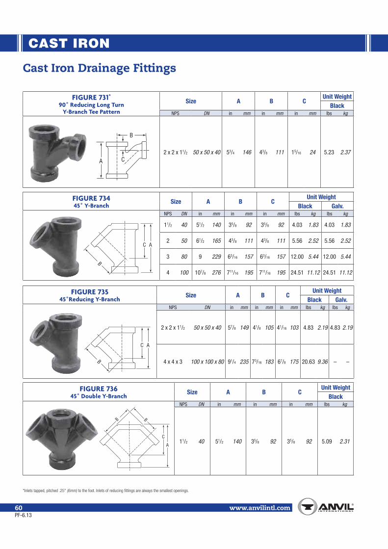
CAST IRON
www.anvilintl.com60
Cast Iron Drainage Fittings
FIGURE 731*
90˚ Reducing Long Turn Y-Branch Tee Pattern
Size A B CUnit Weight
BlackNPS DN in mm in mm in mm lbs kg
2 x 2 x 11/2 50 x 50 x 40 53/4 146 43/8 111 15/16 24 5.23 2.37
FIGURE 73445˚ Y-Branch
Size A B CUnit Weight
Black Galv.NPS DN in mm in mm in mm lbs kg lbs kg
11/2 40 51/2 140 35/8 92 35/8 92 4.03 1.83 4.03 1.83
2 50 61/2 165 43/8 111 43/8 111 5.56 2.52 5.56 2.52
3 80 9 229 63/16 157 63/16 157 12.00 5.44 12.00 5.44
4 100 107/8 276 711/16 195 711/16 195 24.51 11.12 24.51 11.12
FIGURE 73545˚Reducing Y-Branch
Size A B CUnit Weight
Black Galv.NPS DN in mm in mm in mm lbs kg lbs kg
2 x 2 x 11/2 50 x 50 x 40 57/8 149 41/8 105 41/16 103 4.83 2.19 4.83 2.19
4 x 4 x 3 100 x 100 x 80 91/4 235 73/16 183 67/8 175 20.63 9.36 – –
FIGURE 73645˚ Double Y-Branch
Size A B CUnit Weight
BlackNPS DN in mm in mm in mm lbs kg
11/2 40 51/2 140 35/8 92 35/8 92 5.09 2.31
A C
B
AC
B
AC
B
A
B B
C
PF-6.13

CAST IRON
Mal
leab
le Ir
onCa
st Ir
onSm
all S
teel
Fi
tting
sPi
pe N
ippl
es &
Pipe
Cou
plin
gsFo
rged
Ste
elFi
tting
s &
Unio
nsAn
vile
tsCa
taw
issa
J.B.
Sm
ith P
rodu
cts
www.anvilintl.com 61
Cast Iron Drainage Fittings
FIGURE 753Coupling
Size AUnit Weight
Black Galv.NPS DvN in mm lbs kg lbs kg
11/2 40 33/8 86 1.75 0.79 1.75 0.79
FIGURE 744Tucker Connection
Size AUnit Weight
BlackNPS DN in mm lbs kg
11/2 40 4 102 4.04 1.83
2 50 41/2 114 5.40 2.45
4 100 613/16 174 20.00 9.07
FIGURE 752P-Trap
Size A B C CleanOut
WaterSeal
Unit WeightBlack Galv.
NPS DN in mm in mm in mm in mm in mm lbs kg lbs kg
11/2 40 21/8 54 21/4 57 7/8 22 1 25 2 51 4.69 2.13 4.69 2.13
3 80 33/8 86 33/4 95 13/16 30 11/4 32 21/2 64 16.87 7.65 16.87 7.65
FIGURE 754Bath P-Trap
Size A B C D WaterSeal
Unit WeightBlack
NPS DN in mm in mm in mm in mm in mm lbs kg
11/2 40 21/8 54 23/8 60 43/8 111 45/8 117 2 51 3.87 1.76
2 50 21/2 64 213/16 73 55/16 135 55/16 135 2 51 6.25 2.83
A
A CB
Outlet
Inlet
Cleanout
A
AB
Inlet Outlet
DC
PF-6.13

CAST IRON
Note:
www.anvilintl.com62
Cast Iron Flanged FittingsClass 125 (Standard)
PF-11.13
For Listings/Approval Details and Limitations, visit our website at www.anvilintl.com or contact an Anvil Sales Representative.
Standards and SpecificationsDimensions Material Galvanizing**** Thread Pressure Rating Federal/Other
CAST IRON FLANGES AND FLANGED FITTINGSClass 125 (1"-12") ASTM A- 126 (A) or (B) ASTM A-153 ASME B1.20.1+ ASME B16.1Class 125 (14"-up) ASTM A-126 (B) ASTM A-153 ASME B1.20.1+ ASME B16.1Class 250 (1"-12") ASTM A- 126 (A) or (B) ASTM A-153 ASME B1.20.1+ ASME B16.1Class 250 (14"-up) ASTM A-126 (B) ASTM A-153 ASME B1.20.1+ ASME B16.1
SpecificationsAll standard or “Class 125” Cast Iron Flanged Fittings in sizes listed are made to ASME and are marked 125 for pipe sizes 12 NPS (300 DN) and smaller; and have plain faces. Unless otherwise specified, cast iron flanges and fittings are drilled and faced in accordance with ASME B 16.1.
CoatingsFlanged fittings are available in both black and galvanized. Consult an Anvil Representative for available sizes.
SizesSize of all fittings scheduled indicates nominal pipe diameter of ports. Standard reducing elbows carry the same dimensions center-to-face as regular elbows of largest straight size.
OrderingTo order reducing companion flanges, specify threaded or reduced size first, then the outside diameter of flange wanted. For instance, if a reducing flange is required to connect a 5-inch pipe to an 8-inch flanged valve or fitting having a 13 1/2-inch O.D. flange, order: 5 x 13 1/2-inch standard reducing flange.
DimensionsBolt holes, for bolts smaller than 1 3/4 inches (44mm) in diameter are drilled 1/8 inch larger than the bolt diameter; 1 3/4 inch (44mm) and larger, bolt holes are 1/4 inch (6mm) larger than bolt diameter. Bolt holes straddle the center line. Bolt holes are spot faced on order only.
TolerancesAn inspection limit of plus or minus 1/32 inch (1mm) shall be allowed on all center to contact surface dimensions for sizes up to and including 10 NPS (250 DN); plus or minus 1/16 inch (2mm) on sizes larger than 10 NPS (250 DN). Inspection limit of plus or minus 1/16 inch (2mm) shall be allowed on all contact surface to contact surface dimensions for sizes up to and including 10 NPS (250 DN); plus or minus 1/8 inch (3mm) on sizes larger than 10 NPS (250 DN). The largest opening in the fitting governs the tolerance to be applied to all openings.
Cast Iron Flanged Fittings and Cast Iron Flanges
TemperaturePressure
Class 125 Class 2501"–12" 14"–24" 30"–48" 1"–12" 14"–24"
(°F) (°C) psi bar psi bar psi bar psi bar psi bar
-20°to
150°
-28.9to
65.6200 13.8 150 10.3 150 10.3 500 34.5 300 20.7
200° 93.3 190 13.1 135 9.3 115 7.9 460 31.7 280 19.3225° 107.2 180 12.4 130 9.0 100 6.9 440 30.3 270 18.6250° 121.1 175 12.1 125 8.6 85 5.9 415 28.6 260 17.9275° 135.0 170 11.7 120 8.3 65 4.5 395 27.2 250 17.2300° 148.9 165 11.4 110 7.6 50 3.4 375 25.9 240 16.5325° 162.8 155 10.7 105 7.2 – – 355 24.5 230 15.9350° 178.3 150 10.3 100 6.9 – – 335 23.1 220 15.2375° 190.6 145 10.0 – – – – 315 21.7 210 14.5400° 207.8 140 9.7 – – – – 290 20.0 200 13.8425° 218.3 130 9.0 – – – – 270 18.6 – –450° 232.2 125 8.6 – – – – 250 17.2 – –
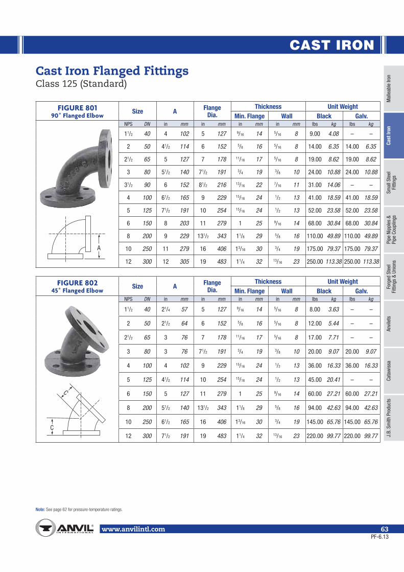
CAST IRON
Mal
leab
le Ir
onCa
st Ir
onSm
all S
teel
Fi
tting
sPi
pe N
ippl
es &
Pipe
Cou
plin
gsFo
rged
Ste
elFi
tting
s &
Unio
nsAn
vile
tsCa
taw
issa
J.B.
Sm
ith P
rodu
cts
Note:
www.anvilintl.com 63
Cast Iron Flanged FittingsClass 125 (Standard)
FIGURE 80190˚ Flanged Elbow
Size A Flange Dia.
Thickness Unit WeightMin. Flange Wall Black Galv.
NPS DN in mm in mm in mm in mm lbs kg lbs kg
11/2 40 4 102 5 127 9/16 14 5/16 8 9.00 4.08 – –
2 50 41/2 114 6 152 5/8 16 5/16 8 14.00 6.35 14.00 6.35
21/2 65 5 127 7 178 11/16 17 5/16 8 19.00 8.62 19.00 8.62
3 80 51/2 140 71/2 191 3/4 19 3/8 10 24.00 10.88 24.00 10.88
31/2 90 6 152 81/2 216 13/16 22 7/16 11 31.00 14.06 – –
4 100 61/2 165 9 229 15/16 24 1/2 13 41.00 18.59 41.00 18.59
5 125 71/2 191 10 254 15/16 24 1/2 13 52.00 23.58 52.00 23.58
6 150 8 203 11 279 1 25 9/16 14 68.00 30.84 68.00 30.84
8 200 9 229 131/2 343 11/8 29 5/8 16 110.00 49.89 110.00 49.89
10 250 11 279 16 406 13/16 30 3/4 19 175.00 79.37 175.00 79.37
12 300 12 305 19 483 11/4 32 13/16 23 250.00 113.38 250.00 113.38
FIGURE 80245˚ Flanged Elbow
Size A Flange Dia.
Thickness Unit WeightMin. Flange Wall Black Galv.
NPS DN in mm in mm in mm in mm lbs kg lbs kg
11/2 40 21/4 57 5 127 9/16 14 5/16 8 8.00 3.63 – –
2 50 21/2 64 6 152 5/8 16 5/16 8 12.00 5.44 – –
21/2 65 3 76 7 178 11/16 17 5/16 8 17.00 7.71 – –
3 80 3 76 71/2 191 3/4 19 3/8 10 20.00 9.07 20.00 9.07
4 100 4 102 9 229 15/16 24 1/2 13 36.00 16.33 36.00 16.33
5 125 41/2 114 10 254 15/16 24 1/2 13 45.00 20.41 – –
6 150 5 127 11 279 1 25 9/16 14 60.00 27.21 60.00 27.21
8 200 51/2 140 131/2 343 11/8 29 5/8 16 94.00 42.63 94.00 42.63
10 250 61/2 165 16 406 13/16 30 3/4 19 145.00 65.76 145.00 65.76
12 300 71/2 191 19 483 11/4 32 13/16 23 220.00 99.77 220.00 99.77
A
C
C
PF-6.13

CAST IRON
Note:
www.anvilintl.com64
FIGURE 80390˚ Reducing Flanged Elbow
Size AUnit Weight
BlackNPS DN NPS DN in mm lbs kg21/2 65 2 50 5 127 18.00 8.16
3 802 50
51/2 14019.00 8.62
21/2 65 22.00 9.98
4 1002 50
61/2 16529.00 13.15
21/2 65 31.00 14.063 80 33.00 14.97
5 1253 80
71/2 19140.00 18.14
4 100 48.00 21.77
6 1503 80
8 20347.00 21.32
4 100 56.00 25.405 125 60.00 27.21
8 2004 100
9 22977.00 34.92
5 125 82.00 37.196 150 90.00 40.82
10 2506 150
11 279125.00 56.69
8 200 150.00 68.03
12 3006 150
12 305165.00 74.83
8 200 190.00 86.1710 250 220.00 99.77
Cast Iron Flanged FittingsClass 125 (Standard)
FIGURE 80490˚ Long Radius Flanged Elbow
Size B FlangeDiameter
Thickness Unit WeightMin. Flange Wall Black
NPS DN in mm in mm in mm in mm lbs kg
2 50 61/2 165 6 152 5/8 16 5/16 8 16.00 7.26
21/2 65 7 178 7 178 11/16 17 5/16 8 23.00 10.43
3 80 73/4 197 71/2 191 3/4 19 3/8 10 28.00 12.70
4 100 9 229 9 229 15/16 24 1/2 13 48.00 21.77
5 125 101⁄4 260 10 254 15⁄16 24 1⁄2 13 62.00 28.12
6 150 111/2 292 11 279 1 25 9/16 14 85.00 38.55
8 200 14 356 131/2 343 11/8 29 5/8 16 145.00 65.76
10 250 161/2 419 16 406 13/16 30 3/4 19 230.00 104.31
12 300 19 483 19 483 11/4 32 13/16 22 350.00 158.73
FIGURE 804R90˚ Long Radius Reducing Flanged Elbow
Reducing Size BUnit Weight
BlackNPS DN in mm lbs kg
4 x 3 100 x 80 9 229 46.00 20.86
5 x 4 125 x 100 101/4 260 58.00 26.30
6 x 4 150 x 100 111/2 292 78.00 35.37
6 x 5 150 x 125 111/2 292 81.00 36.73
8 x 6 200 x 150 14 356 130.00 58.96
10 x 8 250 x 200 161/2 419 205.00 92.97
A
A
B
B
B
B
PF-6.13

CAST IRON
Mal
leab
le Ir
onCa
st Ir
onSm
all S
teel
Fi
tting
sPi
pe N
ippl
es &
Pipe
Cou
plin
gsFo
rged
Ste
elFi
tting
s &
Unio
nsAn
vile
tsCa
taw
issa
J.B.
Sm
ith P
rodu
cts
Note:
www.anvilintl.com 65
FIGURE 80590˚ Flanged Base Elbow
SizeCenterto Base
R
Dia. ofRound Base
S
Thickness Size ofSupporting
Pipe for Base
Unit Weight Base
TRubs
U Black
NPS DN in mm in mm in mm in mm in mm lbs kg
3 80 47/8 124 5 127 9/16 14 1/2 13 11⁄2 38 36.00 16.33
4 100 51/2 140 6 152 5/8 16 1/2 13 2 51 59.00 26.76
6 150 7 178 7 178 11/16 17 5/8 16 21/2 64 110.00 49.89
8 200 83/8 213 9 229 15/16 24 7/8 22 4 102 158.00 71.66
10 250 93/4 248 9 229 15/16 24 7/8 22 4 102 224.00 101.59
12 300 111/4 286 11 279 1 25 1 25 6 152 324.00 146.94
FIGURE 80890˚ Flanged Side Outlet Elbow
Size A FlangeDiameter
Thickness Unit Weight Flange Wall Black
NPS DN in mm in mm in mm in mm lbs kg
4 100 61/2 165 9 229 15/16 24 1/2 13 59.00 26.76
6 150 8 203 11 279 1 25 9/16 14 96.00 43.54
8 200 9 229 131/2 343 11/8 29 5/8 16 150.00 68.03
Cast Iron Flanged FittingsClass 125 (Standard)
R
TS
U
A
A
PF-6.13

CAST IRON
Note:
www.anvilintl.com66
FIGURE 811Flanged Tee
Size A AA FlangeDiameter
Thickness Unit WeightFlange Wall Black Galv.
NPS DN in mm in mm in mm in mm in mm lbs kg lbs kg
11/2 40 4 102 8 203 5 127 9/16 14 5/16 8 15.00 6.80 – –
2 50 41/2 114 9 229 6 152 5/8 16 5/16 8 21.00 9.52 21.00 9.52
21/2 65 5 127 10 254 7 178 11/16 17 5/16 8 30.00 13.61 30.00 13.61
3 80 51/2 140 11 279 71/2 191 3/4 19 3/8 10 37.00 16.78 37.00 16.78
4 100 61/2 165 13 330 9 229 15/16 24 1/2 13 64.00 29.02 64.00 29.02
5 125 71/2 191 15 381 10 254 15/16 24 1/2 13 81.00 36.73 – –
6 150 8 203 16 406 11 279 1 25 9/16 14 105.00 47.62 105.00 47.62
8 200 9 229 18 457 131/2 343 11/8 29 5/8 16 165.00 74.83 165.00 74.83
10 250 11 279 22 559 16 406 13/16 30 3/4 19 270.00 122.45 270.00 122.45
12 300 12 305 24 610 19 483 11/4 32 13/16 22 380.00 172.34 380.00 172.34
Cast Iron Flanged FittingsClass 125 (Standard)
A
AA
PF-6.13

CAST IRON
Mal
leab
le Ir
onCa
st Ir
onSm
all S
teel
Fi
tting
sPi
pe N
ippl
es &
Pipe
Cou
plin
gsFo
rged
Ste
elFi
tting
s &
Unio
nsAn
vile
tsCa
taw
issa
J.B.
Sm
ith P
rodu
cts
Note:
www.anvilintl.com 67
FIGURE 812Flanged Reducing Tee
SizeUnit Weight
Black Galv.NPS DN NPS DN NPS DN lbs kg lbs kg
3 80
2 50 3 80 33.00 14.97 – –
3 80
11⁄2 40 32.00 14.51 – –2 50 34.00 15.42 – –
21/2 65 35.00 15.87 – –4 100 56.00 25.40 – –
4 100
2 50 4 100 50.00 22.68 – –21/2 65 4 100 56.00 25.40 – –
3 803 80 53.00 24.04 – –4 100 59.00 26.76 – –
4 100
2 50 51.00 23.13 – –21/2 65 56.00 25.40 – –3 80 57.00 25.85 – –6 150 88.00 39.91 – –
5 125 5 1253 80 71.00 32.20 – –4 100 80.00 36.28 – –
6 150
3 80 6 150 91.00 41.27 – –
4 1004 100 88.00 39.91 88.00 39.916 150 94.00 42.63 – –
5 125 4 100 91.00 41.27 – –
6 150
2 50 86.00 39.00 – –21/2 65 90.00 40.82 – –3 80 92.00 41.72 – –4 100 97.00 43.99 – –5 125 105.00 47.62 – –8 200 142.00 64.40 – –
8 200
4 1006 150 140.00 63.49 – –8 200 146.00 66.21 – –
6 1504 100 125.00 56.69 – –6 150 144.00 65.31 – –8 200 159.00 72.11 – –
8 2003 80 140.00 63.49 – –4 100 143.00 64.85 143.00 64.856 150 156.00 70.75 156.00 70.75
10 250
8 2006 150 220.00 99.77 – –8 200 232.00 105.22 – –10 250 262.00 118.82 – –
10 2504 100 225.00 102.04 – –6 150 240.00 108.84 – –8 200 262.00 118.82 – –
12 300
8 2008 200 298.00 135.15 – –12 300 340.00 154.20 – –
12 3006 150 323.00 146.49 – –8 200 330.00 149.66 – –10 250 362.00 164.17 – –
Cast Iron Flanged FittingsClass 125 (Standard)
4 NPS(100 DN)
Read as: 6 x 5 x 4 (150 x 125 x 100DN)
6 NPS(150 DN)
5 NPS(125 DN)
PF-6.13

CAST IRON
Note:
www.anvilintl.com68
FIGURE 821Flanged Cross
Size A AA FlangeDiameter
Thickness Unit WeightMin. Flange Wall Black
NPS DN in mm in mm in mm in mm in mm lbs kg
2 50 41/2 114 9 225 6 152 5/8 16 5/16 8 28.00 12.70
21/2 65 5 127 10 250 7 178 11/16 17 5/16 8 39.00 17.69
3 80 51/2 140 11 275 71/2 191 3/4 19 3/8 10 48.00 21.77
4 100 61/2 165 13 325 9 229 15/16 24 1/2 13 82.00 37.19
6 150 8 203 16 400 11 279 1 25 9/16 14 135.00 61.22
8 200 9 229 18 450 131/2 343 11/8 29 5/8 16 210.00 95.24
10 250 11 279 22 550 16 406 13/16 30 3/4 19 330.00 149.66A
A
AA
Cast Iron Flanged FittingsClass 125 (Standard)
FIGURE 823Flanged Lateral
Size Face to FaceD
Center to FaceE
Center to FaceF
FlangeDiameter
Thickness Unit WeightMin. Flange Wall Black
NPS DN in mm in mm in mm in mm in mm in mm lbs kg
2 50 101/2 267 8 203 21/2 64 6 152 5/8 16 5/16 8 25.00 11.34
21/2 65 12 305 91/2 241 21/2 64 7 178 11/16 17 5/16 8 36.00 16.33
3 80 13 330 10 254 3 76 71/2 191 3/4 19 3/8 10 44.00 19.95
4 100 15 381 12 305 3 76 9 229 15/16 24 1/2 13 75.00 34.01
5 125 17 432 131/2 343 31/2 89 10 254 15/16 24 1/2 13 96.00 43.54
6 150 18 457 141/2 368 31/2 89 11 279 1 25 9/16 14 125.00 56.69
8 200 22 559 171/2 445 41/2 114 131/2 343 11/8 29 5/8 16 210.00 95.24
E45
F
D
E
PF-6.13

CAST IRON
Mal
leab
le Ir
onCa
st Ir
onSm
all S
teel
Fi
tting
sPi
pe N
ippl
es &
Pipe
Cou
plin
gsFo
rged
Ste
elFi
tting
s &
Unio
nsAn
vile
tsCa
taw
issa
J.B.
Sm
ith P
rodu
cts
Note:
www.anvilintl.com 69
Cast Iron Flanged FittingsClass 125 (Standard)
FIGURE 825Flanged Concentric Reducer
Size FUnit Weight
Black Galv.NPS DN NPS DN in mm lbs kg lbs kg2 50 11/2 40 5 127 12.00 5.44 – –
21/2 6511/2 40
5 12712.00 5.44 – –
2 50 14.00 6.35 – –
3 8011/2 40
6 15214.00 6.35 – –
2 50 16.00 7.26 – –21/2 65 19.00 8.62 19.00 8.62
4 1002 50
7 17824.00 10.88 24.00 10.88
21/2 65 26.00 11.79 26.00 11.793 80 28.00 12.70 28.00 12.70
5 12521/2 65
8 20331.00 14.06 – –
3 80 32.00 14.51 – –4 100 39.00 17.69 – –
6 150
2 50
9 229
34.00 15.42 – –21/2 65 37.00 16.78 – –3 80 39.00 17.69 – –4 100 47.00 21.32 47.00 21.325 125 50.00 22.68 – –
8 2004 100
11 27966.00 29.93 – –
5 125 71.00 32.20 – –6 150 77.00 34.92 77.00 34.92
10 250
4 100
12 305
85.00 38.55 – –5 125 90.00 40.82 – –6 150 100.00 45.35 – –8 200 120.00 54.42 – –
12 3006 150
14 356140.00 63.49 – –
8 200 155.00 70.29 – –10 250 180.00 81.63 – –
FIGURE 826Flanged Eccentric Reducer
Size FUnit Weight
Black Galv.NPS DN NPS DN in mm lbs kg lbs kg
3 802 50
6 15216.00 7.26 – –
21/2 65 22.00 9.98 – –
4 1002 50
7 17828.00 12.70 – –
21/2 65 28.00 12.70 – –3 80 28.00 12.70 – –
5 125 4 100 8 203 39.00 17.69 – –
6 1503 80
9 22947.00 21.32 – –
4 100 50.00 22.68 50.00 22.685 125 51.00 23.13 – –
8 2004 100
11 27971.00 32.20 – –
5 125 76.00 34.47 – –6 150 77.00 34.92 – –
10 2506 150
12 305107.00 48.53 – –
8 200 120.00 54.42 – –
12 3008 200
14 356155.00 70.29 – –
10 250 180.00 81.63 – –
F
F
PF-6.13

CAST IRON
Note:
www.anvilintl.com70
FIGURE 1011Companion Flange
PipeSize
Diam. of Flange
O
Min.FlangeThickness
Q
Min. Diam. of Hub
X
Min. Length Through
HubY
Unit Weight
Black Galv.
NPS DN in mm in mm in mm in mm lbs kg lbs kg3/4 20 37/8 98 7/16 11 13/4 44 5/8 16 1.50 0.68 1.50 0.68
1 25 41/4 108 7/16 11 115/16 49 11/16 17 1.75 0.79 1.75 0.79
11/4 32 45/8 117 1/2 13 25/16 59 13/16 22 2.00 0.91 2.00 0.91
11/2 40 5 127 9/16 14 29/16 65 7/8 22 2.25 1.02 2.25 1.02
2 50 6 152 5/8 16 31/16 78 1 25 4.00 1.81 4.00 1.81
21/2 65 7 178 11/16 17 39/16 90 11/8 29 6.00 2.72 6.00 2.72
3 80 71/2 191 3/4 19 41/4 108 13/16 30 7.63 3.46 7.63 3.46
31/2 90 81/2 216 13/16 22 413/16 124 11/4 32 9.00 4.08 – –
4 100 9 229 15/16 24 55/16 135 15/16 33 11.75 5.33 11.75 5.33
5 125 10 254 15/16 24 67/16 164 17/16 37 14.00 6.35 14.00 6.35
6 150 11 279 1 25 79/16 192 19/16 40 16.50 7.48 16.50 7.48
8 200 131/2 343 11/8 29 911/16 246 13/4 44 26.00 11.79 26.00 11.79
10 250 16 406 13/16 30 1115/16 303 115/16 49 37.75 17.12 37.75 17.12
12 300 19 483 11/4 32 141/16 357 23/16 56 50.50 22.90 50.50 22.90
Iron FlangesClass 125 (Standard) Class 125 (Standard) Iron Flanges are manufactured to American National Standard ASME B16.1.
X
O
Q Y
FIGURE 1018Blind Flange
Pipe SizeI
Diam. of Flange
O
Min. FlangeThickness
Q
Wall Thickness
V
Unit Weight
Black Galv.NPS DN in mm in mm in mm lbs kg lbs kg
1 25 41/4 108 7/16 11 3/8 10 2.00 0.91 2.00 0.91
11/4 32 45/8 117 1/2 13 7/16 11 2.25 1.02 2.25 1.02
11/2 40 5 127 9/16 14 1/2 13 3.75 1.70 – –
2 50 6 152 5/8 16 9/16 14 4.00 1.81 4.00 1.81
21/2 65 7 178 11/16 17 5/8 16 6.75 3.06 – –
3 80 71/2 191 3/4 19 11/16 17 8.00 3.63 8.00 3.63
31/2 90 81/2 216 13/16 22 3/4 19 11.00 4.99 – –
4 100 9 229 15/16 24 7/8 22 14.00 6.35 14.00 6.35
5 125 10 254 15/16 24 7/8 22 18.00 8.16 18.00 8.16
6 150 11 279 1 25 15/16 24 23.00 10.43 23.00 10.43
8 200 131/2 343 11/8 29 11/16 27 40.00 18.14 40.00 18.14
10 250 16 406 13/16 30 11/8 29 59.00 26.76 – –
12 300 19 483 11/4 32 13/16 22 88.00 39.91 – –
QV
IO
I
IO
Q
V
PF-6.13

CAST IRON
Mal
leab
le Ir
onCa
st Ir
onSm
all S
teel
Fi
tting
sPi
pe N
ippl
es &
Pipe
Cou
plin
gsFo
rged
Ste
elFi
tting
s &
Unio
nsAn
vile
tsCa
taw
issa
J.B.
Sm
ith P
rodu
cts
Note:
www.anvilintl.com 71
Iron FlangesClass 125 (Standard)
FIGURE 1016Reducing Flange
PipeSize
Diam. of Flange
O
Min.FlangeThickness
Q
Min. Diam. of Hub
X
Min. Length Thru Hub
Y
Unit Weight
Black Galv.
/ /
NPS DN in mm in mm in mm in mm lbs kg lbs kg
1 255 127 9/16 14
115/16 49 11/16 17 2.75 1.25 – –
11/4 32 25/16 59 13/16 22 2.50 1.13 – –
1 25
6 152 5/8 16
115/16 49 11/16 17 5.00 2.27 – –
11/4 32 25/16 59 13/16 22 4.75 2.15 – –
11/2 40 29/16 65 7/8 22 4.50 2.04 4.50 2.04
11/2 407 178 11/16 27
29/16 65 7/8 22 7.00 3.17 7.00 3.17
2 50 31/16 78 1 25 6.75 3.06 6.75 3.06
1 25
71/2 191 3/4 19
115/16 49 13/16 22 9.00 4.08 – –
11/2 40 29/16 65 7/8 22 8.75 3.97 8.75 3.97
2 50 31/16 78 1 25 8.50 3.85 8.50 3.85
21/2 65 39/16 90 11/8 29 8.00 3.63 8.00 3.63
3 80 81/2 203 13/16 30 41/4 108 13/16 30 10.00 4.54 – –
11/2 40
9 229 15/16 33
29/16 65 1 25 14.00 6.35 14.00 6.35
2 50 31/16 78 1 25 14.00 6.35 14.00 6.35
21/2 65 39/16 90 11/8 29 13.50 6.12 13.50 6.12
3 80 41/4 108 13/16 30 12.75 5.78 12.75 5.78
31/2 90 413/16 124 11/4 32 12.00 5.44 – –
3 8010 254 15/16 33
41/4 108 13/16 30 17.00 7.71 17.00 7.71
4 100 55/16 135 15/16 33 16.00 7.26 16.00 7.26
11/2 40
11 279 1 25
29/16 65 11/16 27 27.00 12.24 – –
2 50 31/16 78 11/16 27 26.00 11.79 26.00 11.79
21/2 65 39/16 90 11/8 29 25.00 11.34 25.00 11.34
3 80 41/4 108 13/16 30 23.00 10.43 23.00 10.43
4 100 55/16 135 15/16 33 21.00 9.52 21.00 9.52
5 125 67/16 164 17/16 37 19.00 8.62 19.00 8.62
2 50
131/2 343 11/8 29
31/16 78 13/16 30 44.00 19.95 – –
3 80 41/4 108 13/16 30 40.00 18.14 40.00 18.14
4 100 55/16 135 15/16 33 37.00 16.78 37.00 16.78
5 125 67/16 164 17/16 37 34.00 15.42 – –
6 150 79/16 192 19/16 40 31.00 14.06 31.00 14.06
6 15016 406 13/16 30
79/16 192 19/16 40 53.00 24.04 – –
8 200 911/16 246 13/4 44 50.00 22.68 – –
6 15019 483 11/4 32
79/16 192 19/16 40 88.00 39.91 – –
8 200 911/16 246 13/4 44 81.00 36.73 – –
Class 125 (Standard) Iron Flanges are manufactured to American National Standard ASME B16.1.
X
O
Q Y
PF-6.13

CAST IRON
Note:
www.anvilintl.com72
Iron FlangesClass 250 (Extra Heavy)
FIGURE 1025Companion Flange
Pipe SizeDiam. of Flange
O
Min. FlangeThickness
Q
Min. HubDiameter
X
Min. Length Thru Hub
Y
Min. Lengthof Threads
T
Diam. of Raised Face
W
Unit Weight
Black Galv.NPS DN in mm in mm in mm in mm in mm in mm lbs kg lbs kg
11/4 32 51/4 133 3/4 19 21/2 64 1 25 0.76 19 31/16 78 3.75 1.70 – –
11/2 40 61/8 156 13/16 22 23/4 70 11/8 29 0.87 22 39/16 90 5.75 2.61 – –
2 50 61/2 165 7/8 22 35/16 84 11/4 32 1.00 25 43/16 106 6.50 2.95 6.50 2.95
21/2 65 71/2 191 1 25 315/16 100 17/16 37 1.14 29 415/16 125 9.50 4.31 9.50 4.31
3 80 81/4 210 11/8 29 45/8 117 19/16 40 1.20 30 511/16 144 12.33 5.59 12.33 5.59
4 100 10 254 11/4 32 53/4 146 13/4 44 1.30 33 615/16 176 20.00 9.07 20.00 9.07
5 125 11 279 13/8 35 7 178 17/8 48 1.41 36 85/16 211 24.00 10.88 – –
6 150 121/2 318 17/16 37 81/8 206 115/16 49 1.51 38 911/16 246 32.00 14.51 – –
8 200 15 381 15/8 41 101/4 260 23/16 56 1.71 43 1115/16 303 51.00 23.13 – –
YT Q
W
X
O
FIGURE 1030Reducing Flange
Pipe Size
Diam. of Flange
O
Min. Flange
ThicknessQ
Min. Length
Thru HubY
Min. Length
of ThreadsT
Diam. of Raised Face
W
Unit Weight
Black
NPS DN in mm in mm in mm in mm in mm lbs kg
2 50 81/4 210 11/8 29 11/4 32 1.00 25 511/16 144 14.25 6.46
21/2 65 81/4 210 11/8 29 17/16 37 1.14 29 511/16 144 13.50 6.12
3 80 10 254 11/4 32 19/16 40 1.20 30 615/16 176 22.75 10.32
4 100 11 279 13/8 35 13/4 44 1.30 33 85/16 211 30.00 13.61
YQ
W
X
O
T
PF-6.13

CAST IRON
Mal
leab
le Ir
onCa
st Ir
onSm
all S
teel
Fi
tting
sPi
pe N
ippl
es &
Pipe
Cou
plin
gsFo
rged
Ste
elFi
tting
s &
Unio
nsAn
vile
tsCa
taw
issa
J.B.
Sm
ith P
rodu
cts
Note:
www.anvilintl.com 73
Iron FlangesClass 250 (Extra Heavy)
FIGURE 1021Blind Flange
Pipe SizeDiam. of Flange
O
Diam. of Port
I
Min. FlangeThickness
Q
Min. MetalThickness
V
Unit Weight
BlackNPS DN in mm in mm in mm in mm lbs kg
11/2 40 61/8 156 11/2 38 13/16 22 – – 5.30 2.40
2 50 61/2 165 2 51 7/8 22 – – 7.00 3.17
21/2 65 71/2 191 21/2 64 1 25 – – 11.00 4.99
3 80 81/4 210 3 76 11/8 29 – – 14.00 6.35
4 100 10 254 4 102 11/4 32 – – 23.00 10.43
5 125 11 279 5 127 13/8 35 – – 31.00 14.06
6 150 121/2 318 6 152 17/16 37 – – 42.00 19.05
8 200 15 381 8 203 15/8 41 – – 70.00 31.75
Q
Q
V
WI
O
WI
IO
PF-6.13

CAST IRON
Note:
www.anvilintl.com74
Cast Iron Threaded Fittings Safety Valve Discharge Elbows
FIGURE 1538Screwed Cast Iron
Elbow Pipe Size
Riser Pipe Size
AB C D E F G H J K L
Unit WeightBlack
NPS DN in mm in mm in mm in mm in mm in mm in mm in mm in mm in mm in mm lbs kg
21/2 65 31/2 89 211/16 89 45/16 110 81/2 216 15/8 41 115/16 49 21/8 54 23/4 70 3/4 19 – – – – 12.00 5.44
3 80 4 102 31/8 79 47/8 124 91/2 241 15/8 41 25/16 59 29/16 65 31/8 79 3/4 19 – – – – 15.00 6.80
4 100 5 127 33/4 95 53/4 146 11 279 13/4 44 215/16 75 33/16 81 33/4 95 3/4 19 – – – – 27.00 12.24
Following are the advantages of Anvil safety valve discharge elbow for piping connections to safety valves when attached to boilers, etc.:
• Drip pan for removing condensate and rain water casts integral with elbow.
• Strains on safety valve minimized.• Pipe tap J is standard.
With multiple pop safety valve, leakage of vapor at any discharge elbow indicates valve in operation.
Street elbows and flanged elbows furnished on order.
C
L G
Pipe Tap J
F
K
D
B
H
E
NIPPLE9" (229mm) LONG
RISER "A"
PROVIDESUITABLEANCHOR
RECO
MM
ENDE
DLE
NGTH
NOT
LESS
THA
N 7'
- 0"
(2.1
M)
OPEN DRAINTO WASTE
D
PF-6.13
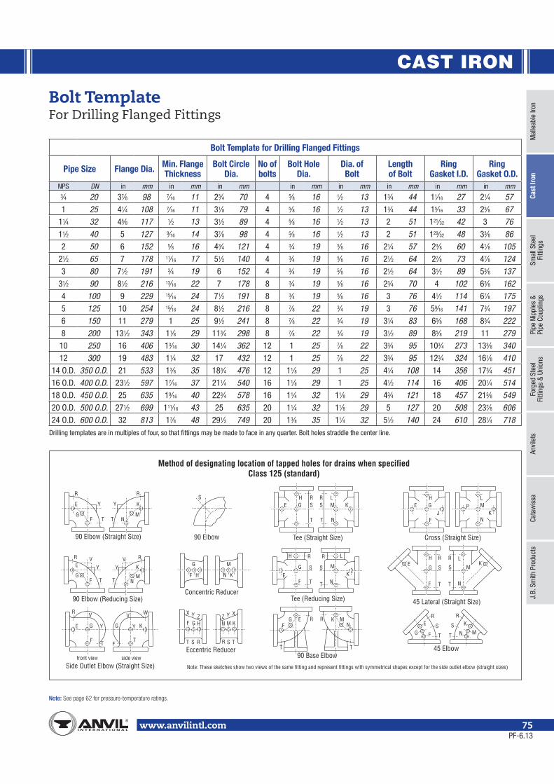
CAST IRON
Mal
leab
le Ir
onCa
st Ir
onSm
all S
teel
Fi
tting
sPi
pe N
ippl
es &
Pipe
Cou
plin
gsFo
rged
Ste
elFi
tting
s &
Unio
nsAn
vile
tsCa
taw
issa
J.B.
Sm
ith P
rodu
cts
Note:
www.anvilintl.com 75
Bolt TemplateFor Drilling Flanged Fittings
Bolt Template for Drilling Flanged Fittings
Pipe Size Flange Dia. Min. Flange Thickness
Bolt Circle Dia.
No of bolts
Bolt Hole Dia.
Dia. of Bolt
Length of Bolt
Ring Gasket I.D.
Ring Gasket O.D.
NPS DN in mm in mm in mm in mm in mm in mm in mm in mm3⁄4 20 37⁄8 98 7⁄16 11 23⁄4 70 4 5⁄8 16 1⁄2 13 13⁄4 44 11⁄16 27 21⁄4 57
1 25 41⁄4 108 7⁄16 11 31⁄8 79 4 5⁄8 16 1⁄2 13 13⁄4 44 15⁄16 33 25⁄8 67
11⁄4 32 45⁄8 117 1⁄2 13 31⁄2 89 4 5⁄8 16 1⁄2 13 2 51 121⁄32 42 3 76
11⁄2 40 5 127 9⁄16 14 37⁄8 98 4 5⁄8 16 1⁄2 13 2 51 129⁄32 48 33⁄8 86
2 50 6 152 5⁄8 16 43⁄4 121 4 3⁄4 19 5⁄8 16 21⁄4 57 23⁄8 60 41⁄8 105
21⁄2 65 7 178 11⁄16 17 51⁄2 140 4 3⁄4 19 5⁄8 16 21⁄2 64 27⁄8 73 47⁄8 124
3 80 71⁄2 191 3⁄4 19 6 152 4 3⁄4 19 5⁄8 16 21⁄2 64 31⁄2 89 53⁄8 137
31⁄2 90 81⁄2 216 13⁄16 22 7 178 8 3⁄4 19 5⁄8 16 23⁄4 70 4 102 63⁄8 162
4 100 9 229 15⁄16 24 71⁄2 191 8 3⁄4 19 5⁄8 16 3 76 41⁄2 114 67⁄8 175
5 125 10 254 15⁄16 24 81⁄2 216 8 7⁄8 22 3⁄4 19 3 76 59⁄16 141 73⁄4 197
6 150 11 279 1 25 91⁄2 241 8 7⁄8 22 3⁄4 19 31⁄4 83 65⁄8 168 83⁄4 222
8 200 131⁄2 343 11⁄8 29 113⁄4 298 8 7⁄8 22 3⁄4 19 31⁄2 89 85⁄8 219 11 279
10 250 16 406 13⁄16 30 141⁄4 362 12 1 25 7⁄8 22 33⁄4 95 103⁄4 273 133⁄8 340
12 300 19 483 11⁄4 32 17 432 12 1 25 7⁄8 22 33⁄4 95 123⁄4 324 161⁄8 410
14 O.D. 350 O.D. 21 533 13⁄8 35 183⁄4 476 12 11⁄8 29 1 25 41⁄4 108 14 356 173⁄4 451
16 O.D. 400 O.D. 231⁄2 597 17⁄16 37 211⁄4 540 16 11⁄8 29 1 25 41⁄2 114 16 406 201⁄4 514
18 O.D. 450 O.D. 25 635 19⁄16 40 223⁄4 578 16 11⁄4 32 11⁄8 29 43⁄4 121 18 457 215⁄8 549
20 O.D. 500 O.D. 271⁄2 699 111⁄16 43 25 635 20 11⁄4 32 11⁄8 29 5 127 20 508 237⁄8 606
24 O.D. 600 O.D. 32 813 17⁄8 48 291⁄2 749 20 13⁄8 35 11⁄4 32 51⁄2 140 24 610 281⁄4 718Drilling templates are in multiples of four, so that fittings may be made to face in any quarter. Bolt holes straddle the center line.
E
F N
E K
R R
G MT T
Y Y G SH R
TT
SR
N
M KL
E PL
KN
M
F
GH
J
F
G M
N KH
E KM
L
NF T T
G S S
H R R
TT
SS
RRH
G
FE
N
MK
L
T T
F
R R
KMNG
S S
X XZ ZY Y
H FE R K M
NRG
T T
F
ER R
G T T
K
N MS S
FF
E
R W
KG G
TT
Y Y
V V
F
ER RV V
GT N
M
K
T
Y Y
S
90 Elbow (Straight Size) 90 Elbow
Side Outlet Elbow (Straight Size)
90 Elbow (Reducing Size)
front view side view
Tee (Straight Size)
90 Base Elbow
Concentric Reducer
Eccentric Reducer
Tee (Reducing Size)
Cross (Straight Size)
45 Lateral (Straight Size)
45 Elbow
Method of designating location of tapped holes for drains when specifiedClass 125 (standard)
Note: These sketches show two views of the same fitting and represent fittings with symmetrical shapes except for the side outlet elbow (straight sizes)
PF-6.13
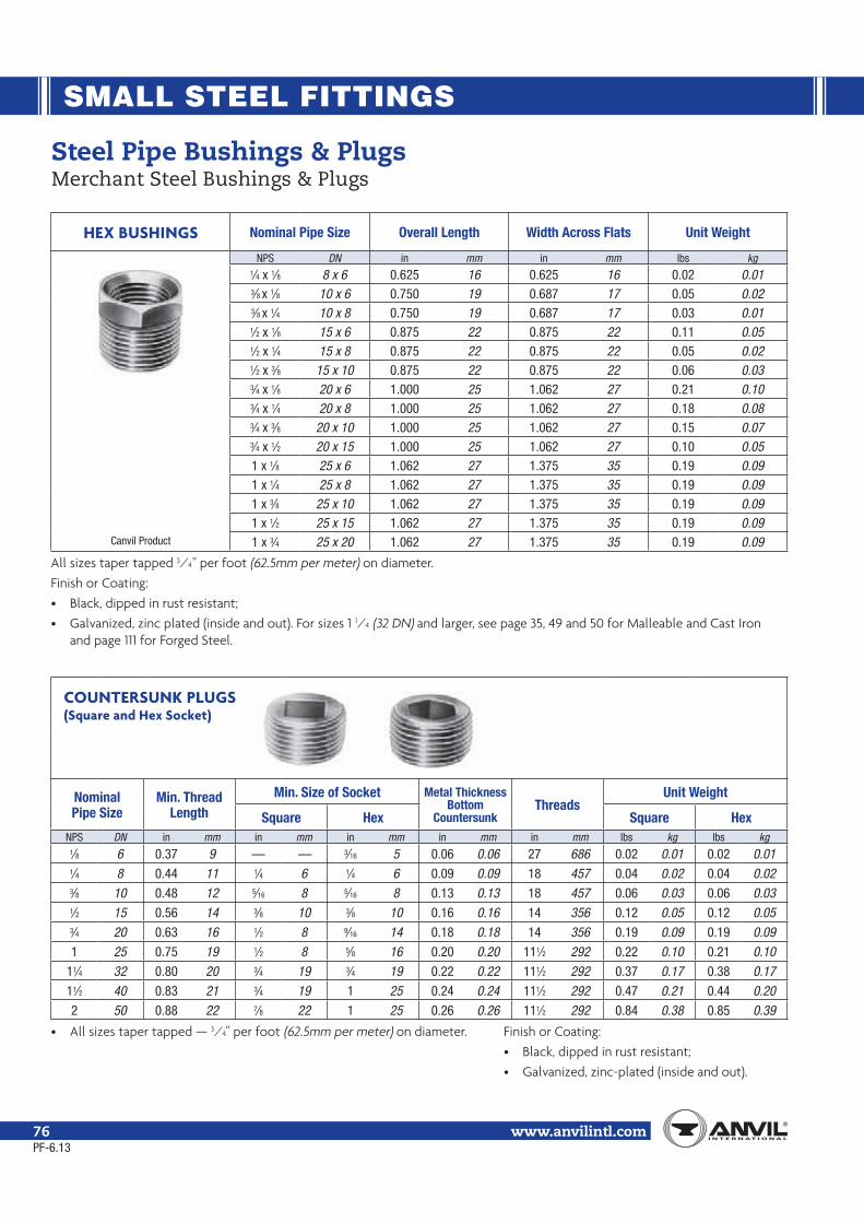
SMALL STEEL FITTINGS
www.anvilintl.com76
HEX BUSHINGS Nominal Pipe Size Overall Length Width Across Flats Unit Weight
Canvil Product
NPS DN in mm in mm lbs kg1⁄4 x 1⁄8 8 x 6 0.625 16 0.625 16 0.02 0.013⁄8 x 1⁄8 10 x 6 0.750 19 0.687 17 0.05 0.023⁄8 x 1⁄4 10 x 8 0.750 19 0.687 17 0.03 0.011⁄2 x 1⁄8 15 x 6 0.875 22 0.875 22 0.11 0.051⁄2 x 1⁄4 15 x 8 0.875 22 0.875 22 0.05 0.021⁄2 x 3⁄8 15 x 10 0.875 22 0.875 22 0.06 0.033⁄4 x 1⁄8 20 x 6 1.000 25 1.062 27 0.21 0.103⁄4 x 1⁄4 20 x 8 1.000 25 1.062 27 0.18 0.083⁄4 x 3⁄8 20 x 10 1.000 25 1.062 27 0.15 0.073⁄4 x 1⁄2 20 x 15 1.000 25 1.062 27 0.10 0.051 x 1⁄8 25 x 6 1.062 27 1.375 35 0.19 0.091 x 1⁄4 25 x 8 1.062 27 1.375 35 0.19 0.091 x 3⁄8 25 x 10 1.062 27 1.375 35 0.19 0.091 x 1⁄2 25 x 15 1.062 27 1.375 35 0.19 0.091 x 3⁄4 25 x 20 1.062 27 1.375 35 0.19 0.09
All sizes taper tapped 3⁄4" per foot (62.5mm per meter) on diameter.
Finish or Coating:
• Black, dipped in rust resistant;
• Galvanized, zinc plated (inside and out). For sizes 1 1⁄4 (32 DN) and larger, see page 35, 49 and 50 for Malleable and Cast Iron and page 111 for Forged Steel.
COUNTERSUNK PLUGS(Square and Hex Socket)
Nominal Pipe Size
Min. Thread Length
Min. Size of Socket Metal Thickness Bottom
CountersunkThreads
Unit Weight
Square Hex Square HexNPS DN in mm in mm in mm in mm in mm lbs kg lbs kg
1⁄8 6 0.37 9 — — 3⁄16 5 0.06 0.06 27 686 0.02 0.01 0.02 0.011⁄4 8 0.44 11 1⁄4 6 1⁄4 6 0.09 0.09 18 457 0.04 0.02 0.04 0.023⁄8 10 0.48 12 5⁄16 8 5⁄16 8 0.13 0.13 18 457 0.06 0.03 0.06 0.031⁄2 15 0.56 14 3⁄8 10 3⁄8 10 0.16 0.16 14 356 0.12 0.05 0.12 0.053⁄4 20 0.63 16 1⁄2 8 9⁄16 14 0.18 0.18 14 356 0.19 0.09 0.19 0.09
1 25 0.75 19 1⁄2 8 5⁄8 16 0.20 0.20 111⁄2 292 0.22 0.10 0.21 0.10
11⁄4 32 0.80 20 3⁄4 19 3⁄4 19 0.22 0.22 111⁄2 292 0.37 0.17 0.38 0.17
11⁄2 40 0.83 21 3⁄4 19 1 25 0.24 0.24 111⁄2 292 0.47 0.21 0.44 0.20
2 50 0.88 22 7⁄8 22 1 25 0.26 0.26 111⁄2 292 0.84 0.38 0.85 0.39
• All sizes taper tapped — 3⁄4" per foot (62.5mm per meter) on diameter. Finish or Coating:• Black, dipped in rust resistant;
• Galvanized, zinc-plated (inside and out).
Steel Pipe Bushings & PlugsMerchant Steel Bushings & Plugs
PF-6.13

SMALL STEEL FITTINGS
Mal
leab
le Ir
onCa
st Ir
onSm
all S
teel
Fi
tting
sPi
pe N
ippl
es &
Pipe
Cou
plin
gsFo
rged
Ste
elFi
tting
s &
Unio
nsAn
vile
tsCa
taw
issa
J.B.
Sm
ith P
rodu
cts
www.anvilintl.com 77
FLUSH BUSHINGS Nominal Pipe Size Length of External Thread, Min.
Length of Internal Thread, Min. Unit Weight
NPS DN in mm in mm lbs kg
1⁄4 x 1⁄8 8 x 6 0.440 11 0.260 7 0.01 0.00
3⁄8 x 1⁄8 10 x 6 0.480 12 0.250 6 0.03 0.01
3⁄8 x 1⁄4 10 x 8 0.480 12 0.400 10 0.02 0.01
1⁄2 x 1⁄4 15 x 8 0.560 14 0.320 8 0.05 0.02
1⁄2 x 3⁄8 15 x 10 0.560 14 0.410 11 0.03 0.01
CAPS Nominal Pipe Size Cap Length Nominal Width Across Flats Unit Weight
NPS DN in mm in mm lbs kg
1⁄8 6 0.563 14 0.560 14 0.02 0.01
1⁄4 8 0.844 22 0.625 16 0.03 0.01
3⁄8 10 0.813 21 0.870 22 0.06 0.03
1⁄2 15 1.063 27 1.062 27 0.11 0.05
3⁄4 20 1.114 28 1.183 30 0.14 0.06
Steel Pipe Bushings, Caps & PlugsMerchant Steel Bushings, Caps & Plugs
SOLID SQUARE HEAD PLUGS
Nominal Pipe Size
Minimum Overall Plug Length
Nominal Width Across Flats Threads Unit Weight
NPS DN in mm in mm in mm lbs kg
1⁄8 6 0.625 16 9⁄32 7 27 686 0.02 0.01
1⁄4 8 0.687 17 3⁄8 10 18 457 0.04 0.02
3⁄8 10 0.812 21 7⁄16 11 18 457 0.06 0.03
1⁄2 15 0.937 24 9⁄16 14 14 356 0.12 0.05
3⁄4 20 1.062 27 5⁄8 16 14 356 0.19 0.09
1 25 1.125 29 13⁄16 22 111⁄2 292 0.34 0.15
11⁄4 32 1.360 35 15⁄16 24 111⁄2 292 0.55 0.25
11⁄2 40 1.450 37 11⁄8 29 111⁄2 292 0.82 0.37
2 50 1.560 40 15⁄16 34 111⁄2 292 1.35 0.61
PF-6.13

PIPE NIPPLES AND PIPE COUPLINGS
www.anvilintl.com78PF-11.13
Standards and SpecificationsDimensions Material Thread Federal/Other
PIPE NIPPLESSteel Pipe - Welded ASTM A733 ASTM A53 Type F or Type E ASME B1.20.1+ WWN 351Steel Pipe - Seamless (High Temp.) ASTM A733 ASTM A106 Gr. B ASME B1.20.1+ WWN 351Brass ASTM B43 ASME B1.20.1+ WWN 351
SpecificationUnless otherwise specified welded nipples ASTM A 53 are furnished on orders for steel nipples in standard and extra strong sizes 1⁄8" – 8" NPS (6 – 200 DN).
Welded steel nipples (A 53 Type F or Type E) are available in standard and extra strong sizes 1⁄8" – 8" NPS (6 – 200 DN), right hand threads, black or galvanized.
Seamless nipples manufactured for the U.S. and International markets are not phosphate coated. Seamless nipples manufactured for Canada are phosphate coated.
Seamless steel pressure tube nipples (ASTM A 106 Grade B) are available in standard and extra strong sizes 1⁄8" – 8" NPS (6 – 200 DN) with right hand threads, black only.
Right and left steel nipples are available in standard and extra heavy weight sizes 1⁄8" – 4" NPS (8 – 50 DN), in 4" (102mm) and 6" (152mm) lengths.
Nipples are available from stock in 1⁄8" – 8" NPS (6 – 200 DN) diameter, close to 12 NPS (300 DN) in length. Sizes 13" – 24" NPS (325 – 600 DN). (Prices on application.)
Steel pipe nipples meet ASTM A733.1⁄8" Schedule 40 and 80 galvanized nipples are all electroplated.
IdentificationWhere possible, each seamless pipe nipple is identified with the following:
• A trade mark
• Seamless designation “SMLS”
• Pipe schedule STD, XS/XH, SCH 160 and XXS/XXH
• Material designation A106 B
• Heat number for traceablity
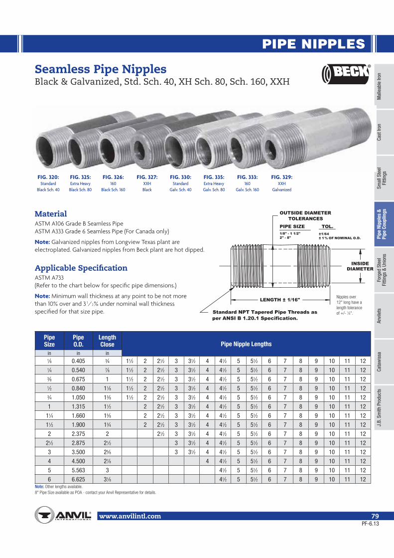
PIPE NIPPLES
Mal
leab
le Ir
onCa
st Ir
onSm
all S
teel
Fi
tting
sPi
pe N
ippl
es &
Pipe
Cou
plin
gsFo
rged
Ste
elFi
tting
s &
Unio
nsAn
vile
tsCa
taw
issa
J.B.
Sm
ith P
rodu
cts
www.anvilintl.com 79
PIPE SIZE TOL.1/8" - 1 1/2"2" - 8"
±1/64± 1% OF NOMINAL O.D.
Standard NPT Tapered Pipe Threads asper ANSI B 1.20.1 Specification.
OUTSIDE DIAMETERTOLERANCES
INSIDEDIAMETER
LENGTH ± 1/16"
Seamless Pipe NipplesBlack & Galvanized, Std. Sch. 40, XH Sch. 80, Sch. 160, XXH
Pipe Size
Pipe O.D.
LengthClose Pipe Nipple Lengths
in in in1⁄8 0.405 3⁄4 11⁄2 2 21⁄2 3 31⁄2 4 41⁄2 5 51⁄2 6 7 8 9 10 11 121⁄4 0.540 7⁄8 11⁄2 2 21⁄2 3 31⁄2 4 41⁄2 5 51⁄2 6 7 8 9 10 11 123⁄8 0.675 1 11⁄2 2 21⁄2 3 31⁄2 4 41⁄2 5 51⁄2 6 7 8 9 10 11 121⁄2 0.840 11⁄8 11⁄2 2 21⁄2 3 31⁄2 4 41⁄2 5 51⁄2 6 7 8 9 10 11 123⁄4 1.050 13⁄8 11⁄2 2 21⁄2 3 31⁄2 4 41⁄2 5 51⁄2 6 7 8 9 10 11 12
1 1.315 11⁄2 2 21⁄2 3 31⁄2 4 41⁄2 5 51⁄2 6 7 8 9 10 11 12
11⁄4 1.660 15⁄8 2 21⁄2 3 31⁄2 4 41⁄2 5 51⁄2 6 7 8 9 10 11 12
11⁄2 1.900 13⁄4 2 21⁄2 3 31⁄2 4 41⁄2 5 51⁄2 6 7 8 9 10 11 12
2 2.375 2 21⁄2 3 31⁄2 4 41⁄2 5 51⁄2 6 7 8 9 10 11 12
21⁄2 2.875 21⁄2 3 31⁄2 4 41⁄2 5 51⁄2 6 7 8 9 10 11 12
3 3.500 25⁄8 3 31⁄2 4 41⁄2 5 51⁄2 6 7 8 9 10 11 12
4 4.500 27⁄8 4 41⁄2 5 51⁄2 6 7 8 9 10 11 12
5 5.563 3 41⁄2 5 51⁄2 6 7 8 9 10 11 12
6 6.625 31⁄8 41⁄2 5 51⁄2 6 7 8 9 10 11 12Note:
MaterialASTM A106 Grade B Seamless PipeASTM A333 Grade 6 Seamless Pipe (For Canada only)
Note: Galvanized nipples from Longview Texas plant are electroplated. Galvanized nipples from Beck plant are hot dipped.
Applicable SpecificationASTM A733(Refer to the chart below for specific pipe dimensions.)
Note: Minimum wall thickness at any point to be not morethan 10% over and 3 1⁄2% under nominal wall thicknessspecified for that size pipe. ⁄8
FIG. 320:Standard
Black Sch. 40
FIG. 325:Extra Heavy
Black Sch. 80
FIG. 326:160
Black Sch. 160
FIG. 330:Standard
Galv. Sch. 40
FIG. 335:Extra HeavyGalv. Sch. 80
FIG. 333:160
Galv. Sch. 160
FIG. 327:XXHBlack
FIG. 329:XXH
Galvanized
PF-6.13
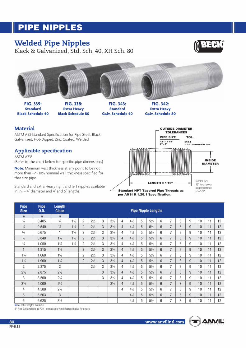
PIPE NIPPLES
www.anvilintl.com80
MaterialASTM A53 Standard Specification for Pipe Steel, Black, Galvanized, Hot-Dipped, Zinc Coated, Welded.
Applicable specificationASTM A733(Refer to the chart below for specific pipe dimensions.)
Note: Minimum wall thickness at any point to be not more than +/- 10% nominal wall thickness specified for that size pipe.
Standard and Extra Heavy right and left nipples available in 1⁄8 – 4" diameter and 4" and 6" lengths.
PIPE SIZE TOL.1/8" - 1 1/2"2" - 8"
±1/64± 1% OF NOMINAL O.D.
Standard NPT Tapered Pipe Threads asper ANSI B 1.20.1 Specification.
OUTSIDE DIAMETERTOLERANCES
INSIDEDIAMETER
LENGTH ± 1/16"
Welded Pipe NipplesBlack & Galvanized, Std. Sch. 40, XH Sch. 80
Pipe Size
Pipe O.D.
LengthClose Pipe Nipple Lengths
in in in1⁄8 0.405 3⁄4 11⁄2 2 21⁄2 3 31⁄2 4 41⁄2 5 51⁄2 6 7 8 9 10 11 121⁄4 0.540 7⁄8 11⁄2 2 21⁄2 3 31⁄2 4 41⁄2 5 51⁄2 6 7 8 9 10 11 123⁄8 0.675 1 11⁄2 2 21⁄2 3 31⁄2 4 41⁄2 5 51⁄2 6 7 8 9 10 11 121⁄2 0.840 11⁄8 11⁄2 2 21⁄2 3 31⁄2 4 41⁄2 5 51⁄2 6 7 8 9 10 11 123⁄4 1.050 13⁄8 11⁄2 2 21⁄2 3 31⁄2 4 41⁄2 5 51⁄2 6 7 8 9 10 11 12
1 1.315 11⁄2 2 21⁄2 3 31⁄2 4 41⁄2 5 51⁄2 6 7 8 9 10 11 12
11⁄4 1.660 15⁄8 2 21⁄2 3 31⁄2 4 41⁄2 5 51⁄2 6 7 8 9 10 11 12
11⁄2 1.900 13⁄4 2 21⁄2 3 31⁄2 4 41⁄2 5 51⁄2 6 7 8 9 10 11 12
2 2.375 2 21⁄2 3 31⁄2 4 41⁄2 5 51⁄2 6 7 8 9 10 11 12
21⁄2 2.875 21⁄2 3 31⁄2 4 41⁄2 5 51⁄2 6 7 8 9 10 11 12
3 3.500 25⁄8 3 31⁄2 4 41⁄2 5 51⁄2 6 7 8 9 10 11 12
31⁄2 4.000 23⁄4 31⁄2 4 41⁄2 5 51⁄2 6 7 8 9 10 11 12
4 4.500 27⁄8 4 41⁄2 5 51⁄2 6 7 8 9 10 11 12
5 5.563 3 41⁄2 5 51⁄2 6 7 8 9 10 11 12
6 6.625 31⁄8 41⁄2 5 51⁄2 6 7 8 9 10 11 12Note:
⁄8
FIG. 339: FIG. 338: FIG. 343: FIG. 342: Standard Extra Heavy Standard Extra Heavy Black Schedule 40 Black Schedule 80 Galv. Schedule 40 Galv. Schedule 80
PF-6.13

PIPE NIPPLES
Mal
leab
le Ir
onCa
st Ir
onSm
all S
teel
Fi
tting
sPi
pe N
ippl
es &
Pipe
Cou
plin
gsFo
rged
Ste
elFi
tting
s &
Unio
nsAn
vile
tsCa
taw
issa
J.B.
Sm
ith P
rodu
cts
www.anvilintl.com 81
Nom. Pipe Size Close 1½" 2" 2½" 3" 3½" 4" 4½" 5" 5½" 6"
No. of Pieces
Approx. Wt. Lbs.
1⁄2 4 3 3 3 2 2 2 1 2 1 2 25 5.001⁄2 20 10 15 10 10 5 10 5 5 5 5 100 18.003⁄4 4 3 3 3 2 2 2 1 2 1 2 25 7.003⁄4 20 10 15 10 10 5 10 5 5 5 5 100 24.001 15 - 15 10 12 5 5 4 3 3 3 75 24.001 5 - 5 3 2 2 2 1 2 1 2 25 10.00
11⁄4 5 - 5 3 2 2 2 1 2 1 2 25 12.0011⁄2 5 - 5 3 2 2 2 1 2 1 2 25 15.002 6 - - 3 3 2 3 1 3 1 3 25 22.00
Nom. Pipe Size Close 1½" 2" 2½" 3" 3½" 4" 4½" 5" 5½" 6"
No. of Pieces
Approx. Wt. Lbs.
1⁄8 6 6 6 6 6 6 6 6 6 6 6 66 6.001⁄4 6 6 6 6 6 6 6 6 6 6 6 66 9.003⁄8 6 6 6 6 6 6 6 6 6 6 6 66 12.001⁄2 6 6 6 6 6 6 6 6 6 6 6 66 14.003⁄4 6 6 6 6 6 6 6 6 6 6 6 66 19.001 6 - 6 6 6 6 6 6 6 6 6 60 26.00
11⁄4 3 - - 3 3 3 3 3 3 3 3 27 19.0011⁄2 3 - - 3 3 3 3 3 3 3 3 27 23.002 3 - - 3 3 3 3 3 3 3 3 27 30.00
Steel Pipe NipplesWelded – Ready Cut Pipe Standard — Schedule 40
“A” ASSORTMENTSMixed Cartons (Black — Figure 339 & Galvanized — Figure 343)
Nom. Pipe Size Close 1½" 2" 2½" 3" 3½" 4" 4½" 5" 5½" 6"
No. of Pieces
Approx. Wt. Lbs.
1⁄8 6 6 6 6 6 6 6 6 6 6 6 66 6.001⁄4 6 6 6 6 6 6 6 6 6 6 6 66 9.003⁄8 6 6 6 6 6 6 6 6 6 6 6 66 12.001⁄2 6 6 6 6 6 6 6 6 6 6 6 66 14.003⁄4 6 6 6 6 6 6 6 6 6 6 6 66 19.001 6 - 6 6 6 6 6 6 6 6 6 60 26.00
11⁄4 6 - 6 6 6 6 6 6 6 6 6 60 33.0011⁄2 6 - 6 6 6 6 6 6 6 6 6 60 41.002 6 - - 6 6 6 6 6 6 6 6 54 53.00
“66” PACKS OR ASSORTED 6 CARTONSBlack — Figure 339 & Galvanized — Figure 343
HANDY PACK ASSORTMENTSMixed Cartons (Black — Figure 339 & Galvanized — Figure 343)
PF-6.13

PIPE NIPPLES
www.anvilintl.com82
Nom. Pipe Size Close 1½" 2" 2½" 3" 3½" 4" 4½" 5" 5½" 6"
No. of Pieces
Approx. Wt. Lbs.
1⁄8 1 1 1 1 1 1 1 1 1 1 1 11 1.001⁄4 1 1 1 1 1 1 1 1 1 1 1 11 1.503⁄8 1 1 1 1 1 1 1 1 1 1 1 11 2.001⁄2 1 1 1 1 1 1 1 1 1 1 1 11 2.503⁄4 1 1 1 1 1 1 1 1 1 1 1 11 3.501 1 - 1 1 1 1 1 1 1 1 1 10 5.00
11⁄4 1 - 1 1 1 1 1 1 1 1 1 10 7.0011⁄2 1 - 1 1 1 1 1 1 1 1 1 10 8.002 1 - - 1 1 1 1 1 1 1 1 9 10.00
21⁄2 1 - - - 1 1 1 1 1 1 1 8 13.303 1 - - - 1 1 1 1 1 1 1 8 15.80
Steel Pipe NipplesWelded – Ready Cut Pipe Standard — Schedule 40, XH Sch. 80
SINGLE RUN PACKSBlack — Figure 339 & Galvanized — Figure 343
Nom. Pipe Size Close 1½" 2" 2½" 3" 3½" 4" 4½" 5" 5½" 6"
No. of Pieces
Approx. Wt. Lbs.
1⁄2 1 1 1 1 1 1 1 1 1 1 1 11 3.203⁄4 1 1 1 1 1 1 1 1 1 1 1 11 4.301 1 - 1 1 1 1 1 1 1 1 1 10 6.10
11⁄4 1 - 1 1 1 1 1 1 1 1 1 10 8.4011⁄2 1 - 1 1 1 1 1 1 1 1 1 10 10.302 1 - - 1 1 1 1 1 1 1 1 9 13.90
SINGLE RUN PACKSBlack Only Extra Heavy — Figure 338
Nom. Pipe Size Close 1½" 2" 2½" 3" 3½" 4" 4½" 5" 5½" 6"
No. of Pieces
Approx. Wt. Lbs.
1⁄2 6 6 6 6 6 6 6 6 6 6 6 66 15.003⁄4 6 6 6 6 6 6 6 6 6 6 6 66 20.001 5 - 5 5 5 5 5 5 5 5 5 50 22.00
TRAVEL TRAYS (Black & Galvanized)
Nom. Pipe Size 18" 24" 30" 36" 42" 48" 54" 60" 66" 72"
1⁄8 5 5 5 5 5 5 5 5 5 51⁄4 5 5 5 5 5 5 5 5 5 53⁄8 5 5 5 5 5 5 5 5 5 51⁄2 5 5 5 5 5 5 5 5 5 53⁄4 5 5 5 5 5 5 5 5 5 51 3 3 3 3 3 3 3 3 3 3
11⁄4 3 3 3 3 3 3 3 3 3 311⁄2 3 3 3 3 3 3 3 3 3 32 2 2 2 2 2 2 2 2 2 2
READY CUT PIPEBlack Extra Long— Figure 339 & Galvanized — Figure 343
PF-6.13

PIPE NIPPLES
Mal
leab
le Ir
onCa
st Ir
onSm
all S
teel
Fi
tting
sPi
pe N
ippl
es &
Pipe
Cou
plin
gsFo
rged
Ste
elFi
tting
s &
Unio
nsAn
vile
tsCa
taw
issa
J.B.
Sm
ith P
rodu
cts
www.anvilintl.com 83
Nom. Pipe Size Length Weight Quantity1⁄8 6 0.13 -1⁄4 6 0.20 -3⁄8 6 0.28 -1⁄2 6 0.40 -3⁄4 6 0.53 -1 6 0.76 -
11⁄4 6 1.04 -11⁄2 6 1.28 -2 6 1.56 -
Nom. Pipe Size Length Weight Quantity1⁄8 4" or 6" 0.09 -1⁄4 4" or 6" 0.13 -3⁄8 4" or 6" 0.18 251⁄2 4" or 6" 0.25 253⁄4 4" or 6" 0.35 251 4" or 6" 0.51 25
11⁄4 4" or 6" 0.68 2511⁄2 4" or 6" 0.80 252 4" or 6" 1.09 25
21⁄2 4" or 6" 1.50 -3 4" or 6" 2.00 -
31⁄2 4" or 6" 2.80 -4 4" or 6" 3.24 -
Steel Pipe Nipples – Welded
TANK NIPPLESBlack — Figure 339 & Galvanized — Figure 343
Nom. Pipe Size Weight Quantity1⁄8 x 1⁄2 0.02 -1⁄4 x 3⁄4 0.03 -3⁄8 x 3⁄4 0.04 -1⁄2 x 3⁄4 0.04 -3⁄4 x 1 0.06 -1 x 1 0.10 -
11⁄4 x 1 0.16 -11⁄2 x 11⁄4 0.17 -2 x 11⁄4 0.28 -21⁄2 x 2 0.87 -3 x 2 1.28 -
4 x 21⁄4 1.11 -
BUTT NIPPLESBlack — Figure. 339 & Galvanized — Fig. 343
RIGHT & LEFT NIPPLESBlack — Figure 339 & Galvanized — Figure 343
PF-6.13

PIPE NIPPLES AND PIPE COUPLINGS
www.anvilintl.com84
1. STEEL NIPPLESa. NPT (TOE) x Plain endb. NPT (TOE) x Plain end square cutc. NPT (TOE) x Plain end square cut and deburred
(Bevel, Ream?)d. NPT (TOE) x Ream other end(ROE)e. Plain end x Plain end (cut blank)(roller cut)(square cut)
(B&O cut)f. ROE x ROE (Ream x Ream)g. NPT (TOE) x Bevel (Specify Bevel, ex. Weld Bevel, 45
degree bevel, etc.)h. Bevel x Bevel (Specify Bevel)i. NPT (TOE) x Straight Thd (Specify NPSL or NPSM)
(depends on nipple length)(Straight thread length can be longer than normal thread length if necessary)
j. Straight Thd x Straight Thd (Specify NPSL or NPSM) (nipple length restrictions)
k. Straight Thread x British Standard Pipe Thread l. NPT (TOE) x BPSTm. BSPT x BSPTn. BSPT x Plain end square cuto. BSPT x Plain end square cut and deburredp. BSPT x ROEq. BSPT x Groover. BSPT X Left Hand Threads. Right Hand Thread x Left Hand Threadt. Left Hand Thread x Left Hand Threadu. Left Hand x Plain endv. LH x Plain end square cutw. LH x Plain end square cut and deburredx. LH x ROEy. LH x Straight Thd (Specify NPSL or NPSM)z. LH x Groove
aa. Grooving of nipples (grooving is outsourced) bb. Sandblasting of nipples (length restrictions)cc. Phosphate finish for nipplesdd. Vibra-Seal coated threads for nipplesee. Yellow Di-chromate plating of nipples
(length restrictions)ff. Galvanized plating of threads for nipples
(length restrictions)gg. Chrome plating of Brass nipples (length restrictions)hh. Any length of nipple from close to 120" in increments
of 1⁄16 of an inchii. Nipple w/NPT tapped hole on the side.jj. Flat ream.kk. Stamping.ll. Stainless Steel Specification ASTM A312
Grade 316 & 304 (Sch. 40 & 80)mm. Tank Nipplesnn. Butt Nipplesoo. Stainless Steelpp. Individually Bar Coded product also available.
NPT National Pipe ThreadNPSL Straight Thread – LocknutNPSM Straight Thread – MechanicalBPST British Standard Thread
2. STEEL COUPLINGSa. Phosphatingb. Special Lengthsc. Electroplate ASTM B633
Specialty Fabrication
PF-11.13

PIPE COUPLINGS
Mal
leab
le Ir
onCa
st Ir
onSm
all S
teel
Fi
tting
sPi
pe N
ippl
es &
Pipe
Cou
plin
gsFo
rged
Ste
elFi
tting
s &
Unio
nsAn
vile
tsCa
taw
issa
J.B.
Sm
ith P
rodu
cts
www.anvilintl.com 85
FIGURE 336Standard, Full & Half
SizeOutside
Diameter (Coupling)
Length
Threads
Unit Weight
Full HalfFull Half
Straight Tapped Taper Tapped Straight Tapped Taper Tapped
NPS DN in mm in mm in mm in mm lbs kg lbs kg lbs kg lbs kg1⁄8 6 0.563 14 13⁄16 22 11⁄32 9 27 686 0.03 0.01 0.03 0.01 0.01 0.00 0.01 0.00
1⁄4 8 0.719 18 13⁄16 30 17⁄32 13 18 457 0.07 0.03 0.07 0.03 0.03 0.01 0.03 0.01
3⁄8 10 0.875 22 13⁄16 30 17⁄32 13 18 457 0.10 0.05 0.10 0.05 0.05 0.02 0.05 0.02
1⁄2 15 1.063 27 19⁄16 40 23⁄32 18 14 356 0.18 0.08 0.18 0.08 0.08 0.04 0.08 0.04
3⁄4 20 1.313 33 15⁄8 41 3⁄4 19 14 356 0.26 0.12 0.26 0.12 0.12 0.05 0.12 0.05
1 25 1.576 40 2 51 15⁄16 24 111⁄2 292 0.42 0.19 0.42 0.19 0.18 0.08 0.18 0.08
11⁄4 32 1.900 48 21⁄16 52 31⁄32 25 111⁄2 292 0.50 0.23 0.50 0.23 0.23 0.10 0.23 0.10
11⁄2 40 2.200 56 21⁄16 52 31⁄32 25 111⁄2 292 0.67 0.30 0.67 0.30 0.32 0.15 0.32 0.15
2 50 2.750 70 21⁄8 54 1 25 111⁄2 292 1.03 0.47 1.03 0.47 0.47 0.21 0.47 0.21
21⁄2 65 3.250 83 31⁄8 79 11⁄2 38 8 203 2.09 0.95 2.15 0.98 0.96 0.44 0.96 0.44
3 80 4.000 102 31⁄4 83 19⁄16 40 8 203 3.36 1.52 3.46 1.57 1.60 0.73 1.60 0.73
31⁄2 90 4.625 117 33⁄8 86 15⁄8 41 8 203 4.82 2.19 5.18 2.35 2.22 1.01 2.22 1.01
4 100 5.000 127 31⁄2 89 111⁄16 43 8 203 4.80 2.18 4.87 2.21 2.11 0.96 2.11 0.96
5 125 6.296 160 33⁄4 95 113⁄16 46 8 203 8.31 3.77 8.75 3.97 3.80 1.72 3.80 1.72
6 150 7.390 188 4 102 113⁄16 46 8 203 11.18 5.07 11.88 5.39 5.28 2.39 5.28 2.39
Steel Pipe CouplingsMerchant Couplings
• Manufactured in accordance with ASTM specification A865 and A589.• Merchant couplings in sizes 1⁄8" NPS (6 DN) through 2" NPS (50 DN) are normally supplied straight tapped. Sizes 2 1⁄2" NPS (65 DN)
and larger are taper tapped.
• Taper tapped standard merchant couplings in sizes 1⁄8" NPS (6 DN) through 2" NPS (50 DN) are available upon request.• API line pipe couplings are used in all sizes over 6" NPS (150 DN).• Couplings from 1⁄8" NPS (6 DN) through 6" NPS (150 DN) are dipped in rust preventative.• Electroplated full couplings are also available.
Note• Half couplings are chamfered on one end and squared on the other.
PF-11.13

PIPE COUPLINGS
www.anvilintl.com86
FIGURE 337Extra Strong (XS), Full & Half
Size Outside Diameter (Coupling)
Length Unit Weight
Full Half Full HalfNPS DN in mm in mm in mm lbs kg lbs kg
1⁄8 6 0.563 14 11⁄16 27 15⁄32 12 0.04 0.02 0.02 0.01
1⁄4 8 0.719 18 15⁄8 41 3⁄4 19 0.09 0.04 0.04 0.02
3⁄8 10 0.875 22 15⁄8 41 3⁄4 19 0.14 0.06 0.06 0.03
1⁄2 15 1.063 27 21⁄8 54 1 25 0.25 0.11 0.11 0.05
3⁄4 20 1.313 33 21⁄8 54 1 25 0.36 0.16 0.17 0.08
1 25 1.576 40 25⁄8 67 11⁄4 32 0.56 0.25 0.26 0.12
11⁄4 32 2.054 52 23⁄4 70 15⁄16 33 1.08 0.49 0.51 0.23
11⁄2 40 2.200 56 23⁄4 70 15⁄16 33 0.98 0.44 0.61 0.28
2 50 2.875 73 27⁄8 73 13⁄8 35 2.01 0.91 0.92 0.42
21⁄2 65 3.375 86 41⁄8 105 2 51 3.53 1.60 1.72 0.78
3 80 4.000 102 41⁄4 108 21⁄16 52 4.61 2.09 2.12 0.96
31⁄2 90 4.625 117 43⁄8 111 21⁄8 54 6.25 2.84 2.97 1.35
4 100 5.200 127 41⁄2 114 23⁄16 56 7.88 3.57 3.84 1.74
5 125 6.296 160 45⁄8 117 23⁄16 56 10.50 4.76 4.85 2.20
6 150 7.390 188 47⁄8 124 23⁄16 56 14.51 6.58 6.85 3.11
Steel Pipe CouplingsMerchant Couplings
• Manufactured in accordance with ASTM Specification A865.• All sizes are taper tapped.
• Non-recessed couplings will be supplied for sizes under 6" NPS unless otherwise specified.• Extra strong half couplings can be supplied in sizes under 6" NPS (150 DN).• Couplings 1⁄8" – 6" NPS (6 – 150 DN) are dipped in rust preventative.
• Electroplated full couplings are also available.
Note• Half couplings are chamfered on one end and squared on the other.
PF-11.13

PIPE COUPLINGS
Mal
leab
le Ir
onCa
st Ir
onSm
all S
teel
Fi
tting
sPi
pe N
ippl
es &
Pipe
Cou
plin
gsFo
rged
Ste
elFi
tting
s &
Unio
nsAn
vile
tsCa
taw
issa
J.B.
Sm
ith P
rodu
cts
www.anvilintl.com 87
• The left hand threaded end of all right and left couplings is knurled for identification, and all are dipped in rust preventative.
• Extra strong right and left couplings are available on request.
Steel Pipe CouplingsMerchant Couplings
Note• The left hand threaded end of all right and left couplings is knurled for identification. All sizes of right and left couplings are
taper tapped 3⁄4" per foot (62.5mm per meter) on the diameter and all are dipped in rust preventative.
FIGURE 346Standard, Right & Left
Size Outside Diameter (Coupling) Length Unit Weight
NPS DN in mm in mm lbs kg
1⁄2 15 1.063 27 19⁄16 40 0.17 0.08
3⁄4 20 1.313 33 15⁄8 41 0.28 0.13
1 25 1.576 40 2 51 0.43 0.20
11⁄4 32 1.900 48 21⁄16 52 0.54 0.24
11⁄2 40 2.200 56 21⁄16 52 0.73 0.33
2 50 2.750 70 21⁄8 54 1.11 0.50
FIGURE 347Extra Strong (XS), Right & Left
Size Outside Diameter (Coupling) Length Unit Weight
NPS DN in mm in mm lbs kg
1⁄2 15 1.063 27 21⁄8 54 0.25 0.11
3⁄4 20 1.313 33 21⁄8 54 0.36 0.16
1 25 1.576 40 25⁄8 67 0.74 0.34
11⁄4 32 2.054 52 23⁄4 70 1.08 0.49
11⁄2 40 2.200 56 23⁄4 70 0.95 0.43
2 50 2.875 73 27⁄8 73 2.01 0.91
PF-6.13

PIPE COUPLINGS
www.anvilintl.com88
FIGURE 348API LIne Pipe Couplings
Size Outside Diameter (Coupling) Length Unit Weight
NPS DN in mm in mm lbs kg1⁄8 6 0.563 14 11⁄16 27 0.04 0.02
1⁄4 8 0.719 18 15⁄8 41 0.10 0.05
3⁄8 10 0.875 22 15⁄8 41 0.13 0.06
1⁄2 15 1.063 27 21⁄8 54 0.24 0.11
3⁄4 20 1.313 33 21⁄8 54 0.35 0.16
1 25 1.576 40 25⁄8 67 0.52 0.24
11⁄4 32 2.054 52 23⁄4 70 1.00 0.45
11⁄2 40 2.200 56 23⁄4 70 0.88 0.40
2 50 2.875 73 27⁄8 73 1.83 0.83
21⁄2 65 3.375 86 41⁄8 105 3.28 1.49
3 80 4.000 102 41⁄4 108 4.09 1.85
31⁄2 90 4.625 117 43⁄8 111 5.92 2.68
4 100 5.200 132 41⁄2 114 7.59 3.44
5 125 6.296 160 45⁄8 117 10.00 4.54
6 150 7.390 188 47⁄8 124 12.92 5.86
8 200 9.625 244 51⁄4 133 23.18 10.51
10 250 11.750 298 53⁄4 146 31.55 14.31
12 300 14.000 356 61⁄8 156 49.27 22.34
Steel Pipe Couplings
• These couplings are manufactured in accordance with American Petroleum Institute Specification 5L.• All sizes are taper tapped 3⁄4" per foot (62.5mm per meter) on the diameter.• All couplings are phosphated unless electroplated.
PF-11.13

PIPE COUPLINGS
Mal
leab
le Ir
onCa
st Ir
onSm
all S
teel
Fi
tting
sPi
pe N
ippl
es &
Pipe
Cou
plin
gsFo
rged
Ste
elFi
tting
s &
Unio
nsAn
vile
tsCa
taw
issa
J.B.
Sm
ith P
rodu
cts
www.anvilintl.com 89
Steel Pipe Couplings
FIGURE 349Water Well Reamed &
Drifted CouplingsSize Outside Diameter
(Coupling) Length Unit Weight
NPS DN in mm in mm lbs kg
11⁄4 32 1.900 48 23⁄4 70 0.60 0.2711⁄2 40 2.200 56 23⁄4 70 0.84 0.382 50 2.750 70 33⁄8 86 1.58 0.72
21⁄2 65 3.250 83 315⁄16 100 2.32 1.053 80 4.000 102 41⁄16 103 3.80 1.72
31⁄2 90 4.625 117 43⁄16 106 5.53 2.514 100 5.200 132 45⁄16 110 7.14 3.245 125 6.296 160 41⁄2 114 9.57 4.346 150 7.390 188 411⁄16 119 12.32 5.598 200 9.625 244 51⁄16 129 22.35 10.1410 250 11.750 298 59⁄16 141 30.60 13.8812 300 14.000 356 515⁄16 151 48.00 21.77
• Manufactured in accordance with ASTM specification A589.
• All sizes are recessed Taper Tapped 3⁄4" per foot on diameter.• Sizes over 2" have threads phosphated and outside painted light blue.
The electroplated have a light blue band around the center of the coupling.
FIGURE 379Shallow Well Couplings
Size Outside Diameter (Coupling) Length Unit Weight
NPS DN in mm in mm lbs kg
11⁄4 32 2.054 52 23⁄4 70 1.03 0.47
11⁄2 40 2.200 56 23⁄4 70 0.90 0.41
2 50 2.875 73 27⁄8 73 1.86 0.84
• The 1 1⁄4" are Straight Tapped and recessed.• The 1 1⁄2 and 2" are Taper Tapped 3⁄4" per foot on diameter and recessed.• The 2" threads are electroplated.
FIGURE 350#9 Drive Couplings
Size Outside Diameter (Coupling) Length Unit Weight
NPS DN in mm in mm lbs kg
11⁄4 32 2.054 52 23⁄4 70 1.00 0.45
11⁄2 40 2.200 56 23⁄4 70 0.84 0.38
2 50 2.875 73 33⁄8 86 2.14 0.97
• All sizes are Taper Tapped 3⁄4" per foot on diameter.
PF-11.13

FORGED STEEL FITTINGS
www.anvilintl.com90PF-11.13
Standards and SpecificationsDimensions Material Thread Pressure Rating
FORGED STEEL THREADED FITTINGSClass 2000, 3000, 6000 ASTM Al05, ASTM A182, ASTM A350 ASMEB1.20.1+
Forged Steel FittingsIn accordance with ASME standard B16.11 - “Forged Fittings, Socket-Welding and Threaded” this table shows the schedule of pipe corresponding to each class of fitting for rating purposes.
PRESSURE RATINGS
ClassSchedule
N.P.T. S.W.2000 80 –
3000 160 80
6000 XXS/XXH 160
MaterialsThe steel for Anvil Forged Carbon Steel Fittings consists of forging, bars, seamless pipe or tubes which conform to the requirements for melting process, chemical composition and mechanical properties of ASTM A105.
Design BasisASME B16.11 - Forged fittings, socket-weld and threaded
DimensionsASME B16.11, unless otherwise noted
ThreadsANSI/ASME B1.20.1 NPT Threads
CROSS11⁄2 x 3⁄4 x 11⁄4 x 1⁄2
11⁄4
SideOutlet
1⁄2
3⁄4
11⁄2
Branch
Run
TEE11⁄2 x 3⁄4 x 11⁄4
3⁄4
11⁄4
11⁄2
CROSS
38 x 19 x 32 x 13 mm
32
SideOutlet
13
38
Branch
Run
TEE
38 x 19 x 32 mm
1919
38
Reducing FittingsReducing elbows, tees and crosses are available in both threaded and socket-welding.
On reducing tees and crosses give the size of the largest run opening; then give the opposite opening. On a tee give the branch size last. On a cross give the largest side outlet third and the opposite opening last.
ASME B16.11 provides that the maximum allowable pressure of a fitting be computed in accordance with the applicable piping code or regulation for straight seamless pipe or for material of equivalent composition and mechanical properties to the fitting. Any corrosion or mechanical allowances and any reduction in allowable stress due to temperature or other service conditions must be applied to the pipe and fitting alike.

FORGED STEEL FITTINGS
Mal
leab
le Ir
onCa
st Ir
onSm
all S
teel
Fi
tting
sPi
pe N
ippl
es &
Pipe
Cou
plin
gsFo
rged
Ste
el
Fitti
ngs
& U
nion
sAn
vile
tsCa
taw
issa
J.B.
Sm
ith P
rodu
cts
www.anvilintl.com 91
Forged Steel Fittings Class 2000 Threaded
FIGURE 210190˚ Elbows
Size A H Unit Weight
NPS DN in mm in mm lbs kg
1⁄4 8 0.81 21 0.88 22 0.18 0.08
3⁄8 10 0.97 25 1.00 25 0.28 0.13
1⁄2 15 1.12 28 1.31 33 0.55 0.25
3⁄4 20 1.31 33 1.50 38 0.72 0.33
1 25 1.50 38 1.81 46 1.22 0.55
11⁄4 32 1.75 44 2.19 56 1.65 0.75
11⁄2 40 2.00 51 2.44 62 2.12 0.96
2 50 2.38 60 2.97 75 3.78 1.71
21⁄2 65 3.00 76 3.62 92 6.50 2.95
3 80 3.38 86 4.31 109 11.10 5.03
4 100 4.19 106 5.75 146 22.30 10.11
FIGURE 210245˚ Elbows
Size C H Unit Weight
NPS DN in mm in mm lbs kg
1⁄4 8 0.69 17 0.88 22 0.16 0.07
3⁄8 10 0.75 19 1.00 25 0.25 0.11
1⁄2 15 0.88 22 1.31 33 0.48 0.22
3⁄4 20 1.00 25 1.50 38 0.57 0.26
1 25 1.12 28 1.81 46 0.88 0.40
11⁄4 32 1.31 33 2.19 56 1.32 0.60
11⁄2 40 1.38 35 2.44 62 1.62 0.73
2 50 1.69 43 2.97 75 2.83 1.28
21⁄2 65 2.06 52 3.62 92 7.70 3.49
3 80 2.50 64 4.31 109 12.00 5.44
H
A
HC
PF-6.13

FORGED STEEL FITTINGS
www.anvilintl.com92
Forged Steel Fittings Class 2000 Threaded
FIGURE 2103Tees
Size A H Unit Weight
NPS DN in mm in mm lbs kg
1⁄4 8 0.81 21 0.88 22 0.25 0.11
3⁄8 10 0.97 25 1.00 25 0.37 0.17
1⁄2 15 1.12 28 1.31 33 0.62 0.28
3⁄4 20 1.31 33 1.50 38 0.43 0.20
1 25 1.50 38 1.81 46 1.33 0.60
11⁄4 32 1.75 44 2.19 56 2.10 0.95
11⁄2 40 2.00 51 2.44 62 2.80 1.27
2 50 2.38 60 2.97 75 4.50 2.04
21⁄2 65 3.00 76 3.62 92 9.10 4.13
3 80 3.38 86 4.31 109 13.50 6.12
4 100 4.19 106 5.75 146 32.00 14.51
FIGURE 2104Crosses
Size A H Unit Weight
NPS DN in mm in mm lbs kg
1⁄4 8 0.81 21 0.88 22 0.50 0.23
3⁄8 10 0.97 25 1.00 25 0.40 0.18
1⁄2 15 1.12 28 1.31 33 0.85 0.39
3⁄4 20 1.31 33 1.50 38 1.10 0.50
1 25 1.50 38 1.81 46 1.70 0.77
11⁄4 32 1.75 44 2.19 56 2.40 1.09
11⁄2 40 2.00 51 2.44 62 3.20 1.45
2 50 2.38 60 2.97 75 5.20 2.36
21⁄2 65 3.00 76 3.62 92 16.50 7.48
3 80 3.38 86 4.31 109 20.00 9.07
H
A
H
A
PF-6.13

FORGED STEEL FITTINGS
Mal
leab
le Ir
onCa
st Ir
onSm
all S
teel
Fi
tting
sPi
pe N
ippl
es &
Pipe
Cou
plin
gsFo
rged
Ste
el
Fitti
ngs
& U
nion
sAn
vile
tsCa
taw
issa
J.B.
Sm
ith P
rodu
cts
www.anvilintl.com 93
Forged Steel Fittings Class 3000 Threaded
FIGURE 211190˚ Elbows
Size A H Unit Weight
NPS DN in mm in mm lbs kg1⁄8 6 0.81 21 0.88 22 0.23 0.101⁄4 8 0.97 25 1.00 25 0.35 0.163⁄8 10 1.12 28 1.31 33 0.66 0.301⁄2 15 1.31 33 1.50 38 0.93 0.423⁄4 20 1.50 38 1.81 46 1.48 0.671 25 1.75 44 2.19 56 2.30 1.04
11⁄4 32 2.00 51 2.44 62 2.68 1.2211⁄2 40 2.38 60 2.97 75 5.30 2.402 50 2.50 64 3.31 84 5.85 2.65
21⁄2 65 3.25 83 4.00 102 10.00 4.543 80 3.75 95 4.75 121 17.20 7.804 100 4.50 114 6.00 152 29.30 13.29
FIGURE 211245˚ Elbows
Size C H Unit Weight
NPS DN in mm in mm lbs kg1⁄8 6 0.69 17 0.88 22 0.18 0.081⁄4 8 0.75 19 1.00 25 0.25 0.113⁄8 10 0.88 22 1.31 33 0.53 0.241⁄2 15 1.00 25 1.50 38 0.78 0.353⁄4 20 1.12 28 1.81 46 1.20 0.541 25 1.31 33 2.19 56 1.90 0.86
11⁄4 32 1.38 35 2.44 62 2.30 1.0411⁄2 40 1.69 43 2.97 75 4.16 1.892 50 1.72 44 3.31 84 5.12 2.32
21⁄2 65 2.06 52 4.00 102 7.70 3.493 80 2.50 64 4.75 121 12.00 5.444 100 3.12 79 6.00 152 19.70 8.93
FIGURE 2114Tees
Size A H Unit Weight
NPS DN in mm in mm lbs kg1⁄8 6 0.81 21 0.88 22 0.31 0.141⁄4 8 0.97 25 1.00 25 0.42 0.193⁄8 10 1.12 28 1.31 33 0.93 0.421⁄2 15 1.31 33 1.50 38 1.20 0.543⁄4 20 1.50 38 1.81 46 1.84 0.831 25 1.75 44 2.19 56 3.05 1.38
11⁄4 32 2.00 51 2.44 62 3.62 1.6411⁄2 40 2.38 60 2.97 75 6.65 3.022 50 2.50 64 3.31 84 7.15 3.24
21⁄2 65 3.25 83 4.00 102 13.70 6.213 80 3.75 95 4.75 121 21.00 9.524 100 4.50 114 6.00 152 38.00 17.23
H
A
HC
H
A
PF-11.13

FORGED STEEL FITTINGS
www.anvilintl.com94
Forged Steel Fittings Class 3000 Threaded
FIGURE 2115Crosses
Size A H Unit Weight
NPS DN in mm in mm lbs kg1⁄8 6 0.81 21 0.88 22 – –1⁄4 8 0.97 25 1.00 25 – –3⁄8 10 1.12 28 1.31 33 – –1⁄2 15 1.31 33 1.50 38 1.40 0.633⁄4 20 1.50 38 1.81 46 2.10 0.95
1 25 1.75 44 2.19 56 3.50 1.59
11⁄4 32 2.00 51 2.44 62 4.30 1.95
11⁄2 40 2.38 60 2.97 75 8.20 3.72
2 50 2.50 64 3.31 84 8.40 3.81
21⁄2 65 3.25 83 4.00 102 17.10 7.76
3 80 3.75 95 4.75 121 20.00 9.07
4 100 4.50 114 6.00 152 32.00 14.51
FIGURE 211390˚ Street Elbows
Size A G H Unit Weight
NPS DN in mm in mm in mm lbs kg1⁄8 6 0.75 19 1.00 25 0.75 19 – –1⁄4 8 0.88 22 1.25 32 1.00 25 0.23 0.103⁄8 10 1.00 25 1.50 38 1.25 32 0.38 0.171⁄2 15 1.12 28 1.62 41 1.50 38 0.53 0.243⁄4 20 1.38 35 1.88 48 1.75 44 0.88 0.40
1 25 1.75 44 2.25 57 2.00 51 1.40 0.63
11⁄4 32 2.00 51 2.62 66 2.44 62 2.40 1.09
11⁄2 40 2.12 54 2.81 71 2.75 70 2.90 1.32
2 50 2.50 64 3.31 84 3.31 84 5.00 2.27
FIGURE 2116Laterals
Size B K L Unit Weight
NPS DN in mm in mm in mm lbs kg
1⁄2 15 1.56 39.62 2.56 65.02 3.56 90.42 1.75 0.79
3⁄4 20 1.84 46.74 3.00 76.20 4.13 104.90 2.75 1.24
1 25 2.22 56.39 3.50 88.90 4.81 122.17 4.63 2.10
11⁄4 32 2.50 63.50 3.94 100.08 5.38 136.65 5.50 2.48
11⁄2 40 3.03 79.96 4.75 120.65 6.44 163.58 10.81 4.91
2 50 3.34 84.84 5.00 127.00 6.63 168.40 11.50 5.23
H
A
G
H
A
B
L
K
PF-11.13
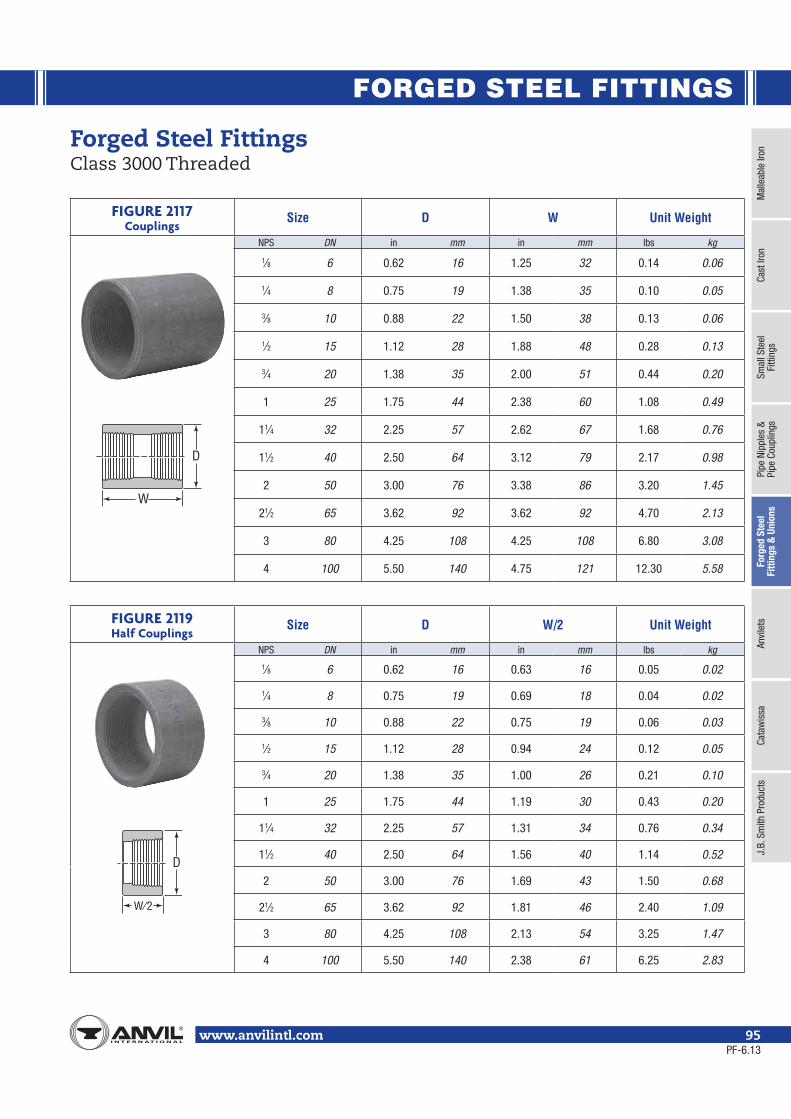
FORGED STEEL FITTINGS
Mal
leab
le Ir
onCa
st Ir
onSm
all S
teel
Fi
tting
sPi
pe N
ippl
es &
Pipe
Cou
plin
gsFo
rged
Ste
el
Fitti
ngs
& U
nion
sAn
vile
tsCa
taw
issa
J.B.
Sm
ith P
rodu
cts
www.anvilintl.com 95
Forged Steel Fittings Class 3000 Threaded
FIGURE 2117Couplings
Size D W Unit Weight
NPS DN in mm in mm lbs kg
1⁄8 6 0.62 16 1.25 32 0.14 0.06
1⁄4 8 0.75 19 1.38 35 0.10 0.05
3⁄8 10 0.88 22 1.50 38 0.13 0.06
1⁄2 15 1.12 28 1.88 48 0.28 0.13
3⁄4 20 1.38 35 2.00 51 0.44 0.20
1 25 1.75 44 2.38 60 1.08 0.49
11⁄4 32 2.25 57 2.62 67 1.68 0.76
11⁄2 40 2.50 64 3.12 79 2.17 0.98
2 50 3.00 76 3.38 86 3.20 1.45
21⁄2 65 3.62 92 3.62 92 4.70 2.13
3 80 4.25 108 4.25 108 6.80 3.08
4 100 5.50 140 4.75 121 12.30 5.58
FIGURE 2119Half Couplings
Size D W/2 Unit Weight
NPS DN in mm in mm lbs kg
1⁄8 6 0.62 16 0.63 16 0.05 0.02
1⁄4 8 0.75 19 0.69 18 0.04 0.02
3⁄8 10 0.88 22 0.75 19 0.06 0.03
1⁄2 15 1.12 28 0.94 24 0.12 0.05
3⁄4 20 1.38 35 1.00 26 0.21 0.10
1 25 1.75 44 1.19 30 0.43 0.20
11⁄4 32 2.25 57 1.31 34 0.76 0.34
11⁄2 40 2.50 64 1.56 40 1.14 0.52
2 50 3.00 76 1.69 43 1.50 0.68
21⁄2 65 3.62 92 1.81 46 2.40 1.09
3 80 4.25 108 2.13 54 3.25 1.47
4 100 5.50 140 2.38 61 6.25 2.83
D
W
D
W⁄2
PF-6.13

FORGED STEEL FITTINGS
www.anvilintl.com96
Forged Steel Fittings Class 3000 Threaded
FIGURE 2118Reducing Couplings
Size D W Unit Weight
NPS DN NPS DN in mm in mm lbs kg
1⁄4 8 1⁄8 6 0.75 19 1.38 35 0.10 0.05
3⁄8 10 1⁄8 6 0.88 22 1.50 38 0.15 0.07
1⁄2 15 1⁄8 6 1.12 28 1.88 48 0.35 0.16
3⁄4 20 1⁄8 6 1.38 35 2.00 51 0.52 0.24
1 25 1⁄8 6 1.75 44 2.38 60 1.10 0.50
11⁄4 32 1⁄4 8 2.25 57 2.62 67 2.08 0.94
11⁄2 40 1⁄4 8 2.50 64 3.12 79 2.93 1.33
2 50 1⁄4 8 3.00 76 3.38 86 4.40 2.00
21⁄2 65 3⁄4 20 3.62 92 3.62 92 7.50 3.40
3 80 3⁄4 20 4.25 108 4.25 108 11.00 4.99
4 100 11⁄2 40 5.50 140 4.75 121 20.50 9.30
FIGURE 2120Pipe Caps
Size D P Unit Weight
NPS DN in mm in mm lbs kg
1⁄8 6 0.62 16 0.75 19 0.07 0.03
1⁄4 8 0.75 19 1.00 25 0.08 0.04
3⁄8 10 0.88 22 1.00 25 0.11 0.05
1⁄2 15 1.12 28 1.25 32 0.23 0.10
3⁄4 20 1.38 35 1.44 37 0.40 0.18
1 25 1.75 44 1.62 41 0.79 0.36
11⁄4 32 2.25 57 1.75 44 1.21 0.55
11⁄2 40 2.50 64 1.75 44 1.75 0.79
2 50 3.00 76 1.88 48 2.46 1.12
21⁄2 65 3.62 92 2.38 60 4.37 1.98
3 80 4.25 108 2.56 65 6.50 2.95
4 100 5.50 140 2.69 68 11.30 5.12
D
W
D
P
PF-6.13
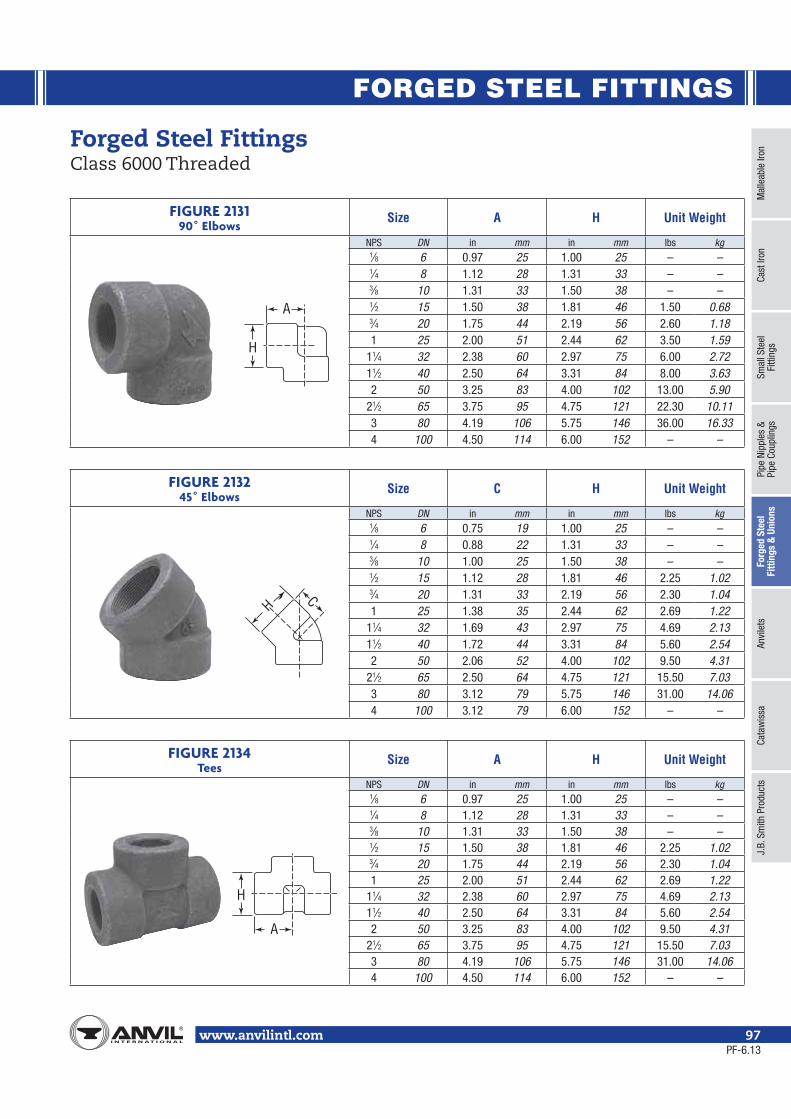
FORGED STEEL FITTINGS
Mal
leab
le Ir
onCa
st Ir
onSm
all S
teel
Fi
tting
sPi
pe N
ippl
es &
Pipe
Cou
plin
gsFo
rged
Ste
el
Fitti
ngs
& U
nion
sAn
vile
tsCa
taw
issa
J.B.
Sm
ith P
rodu
cts
www.anvilintl.com 97
Forged Steel Fittings Class 6000 Threaded
FIGURE 213190˚ Elbows
Size A H Unit Weight
NPS DN in mm in mm lbs kg1⁄8 6 0.97 25 1.00 25 – –1⁄4 8 1.12 28 1.31 33 – –3⁄8 10 1.31 33 1.50 38 – –1⁄2 15 1.50 38 1.81 46 1.50 0.683⁄4 20 1.75 44 2.19 56 2.60 1.181 25 2.00 51 2.44 62 3.50 1.59
11⁄4 32 2.38 60 2.97 75 6.00 2.7211⁄2 40 2.50 64 3.31 84 8.00 3.632 50 3.25 83 4.00 102 13.00 5.90
21⁄2 65 3.75 95 4.75 121 22.30 10.113 80 4.19 106 5.75 146 36.00 16.334 100 4.50 114 6.00 152 – –
FIGURE 213245˚ Elbows
Size C H Unit Weight
NPS DN in mm in mm lbs kg1⁄8 6 0.75 19 1.00 25 – –1⁄4 8 0.88 22 1.31 33 – –3⁄8 10 1.00 25 1.50 38 – –1⁄2 15 1.12 28 1.81 46 2.25 1.023⁄4 20 1.31 33 2.19 56 2.30 1.041 25 1.38 35 2.44 62 2.69 1.22
11⁄4 32 1.69 43 2.97 75 4.69 2.1311⁄2 40 1.72 44 3.31 84 5.60 2.542 50 2.06 52 4.00 102 9.50 4.31
21⁄2 65 2.50 64 4.75 121 15.50 7.033 80 3.12 79 5.75 146 31.00 14.064 100 3.12 79 6.00 152 – –
FIGURE 2134Tees
Size A H Unit Weight
NPS DN in mm in mm lbs kg1⁄8 6 0.97 25 1.00 25 – –1⁄4 8 1.12 28 1.31 33 – –3⁄8 10 1.31 33 1.50 38 – –1⁄2 15 1.50 38 1.81 46 2.25 1.023⁄4 20 1.75 44 2.19 56 2.30 1.041 25 2.00 51 2.44 62 2.69 1.22
11⁄4 32 2.38 60 2.97 75 4.69 2.1311⁄2 40 2.50 64 3.31 84 5.60 2.542 50 3.25 83 4.00 102 9.50 4.31
21⁄2 65 3.75 95 4.75 121 15.50 7.033 80 4.19 106 5.75 146 31.00 14.064 100 4.50 114 6.00 152 – –
H
A
HC
H
A
PF-6.13
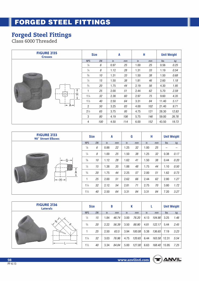
FORGED STEEL FITTINGS
www.anvilintl.com98
Forged Steel Fittings Class 6000 Threaded
FIGURE 2135Crosses
Size A H Unit Weight
NPS DN in mm in mm lbs kg1⁄8 6 0.97 25 1.00 25 0.56 0.251⁄4 8 1.12 28 1.31 33 1.19 0.543⁄8 10 1.31 33 1.50 38 1.50 0.681⁄2 15 1.50 38 1.81 46 2.60 1.183⁄4 20 1.75 44 2.19 56 4.30 1.95
1 25 2.00 51 2.44 62 5.70 2.59
11⁄4 32 2.38 60 2.97 75 9.60 4.35
11⁄2 40 2.50 64 3.31 84 11.40 5.17
2 50 3.25 83 4.00 102 21.40 9.71
21⁄2 65 3.75 95 4.75 121 28.30 12.83
3 80 4.19 106 5.75 146 59.00 26.76
4 100 4.50 114 6.00 152 43.50 19.73
FIGURE 213390˚ Street Elbows
Size A G H Unit Weight
NPS DN in mm in mm in mm lbs kg
1⁄8 6 0.88 22 1.25 32 1.00 25 – –
1⁄4 8 1.00 25 1.50 38 1.25 32 0.38 0.17
3⁄8 10 1.12 28 1.62 41 1.50 38 0.44 0.20
1⁄2 15 1.38 35 1.88 48 1.75 44 1.10 0.50
3⁄4 20 1.75 44 2.25 57 2.00 51 1.62 0.73
1 25 2.00 51 2.62 66 2.44 62 2.80 1.27
11⁄4 32 2.12 54 2.81 71 2.75 70 3.80 1.72
11⁄2 40 2.50 64 3.31 84 3.31 84 7.20 3.27
FIGURE 2136Laterals
Size B K L Unit Weight
NPS DN in mm in mm in mm lbs kg
1⁄2 15 1.84 46.74 3.00 76.20 4.13 104.90 3.25 1.46
3⁄4 20 2.22 56.39 3.50 88.90 4.81 122.17 5.44 2.45
1 25 2.50 63.5 3.94 100.08 5.38 136.65 7.19 3.23
11⁄4 32 3.03 76.96 4.75 120.65 6.44 163.58 12.31 5.54
11⁄2 40 3.34 84.84 5.00 127.00 6.63 168.40 15.95 7.25
H
A
B
L
K
H
A
G
PF-6.13

FORGED STEEL FITTINGS
Mal
leab
le Ir
onCa
st Ir
onSm
all S
teel
Fi
tting
sPi
pe N
ippl
es &
Pipe
Cou
plin
gsFo
rged
Ste
el
Fitti
ngs
& U
nion
sAn
vile
tsCa
taw
issa
J.B.
Sm
ith P
rodu
cts
www.anvilintl.com 99
Forged Steel Fittings Class 6000 Threaded
FIGURE 2137Couplings
Size D W Unit Weight
NPS DN in mm in mm lbs kg
1⁄8 6 0.88 22 1.25 32 0.17 0.08
1⁄4 8 1.00 25 1.38 35 0.30 0.14
3⁄8 10 1.25 32 1.50 38 0.45 0.20
1⁄2 15 1.50 38 1.88 48 0.70 0.32
3⁄4 20 1.75 44 2.00 51 1.15 0.52
1 25 2.25 57 2.38 60 1.83 0.83
11⁄4 32 2.50 64 2.62 67 2.08 0.94
11⁄2 40 3.00 76 3.12 79 3.95 1.79
2 50 3.62 92 3.38 86 6.50 2.95
21⁄2 65 4.25 108 3.62 92 – –
3 80 5.00 127 4.25 108 – –
4 100 6.25 159 4.75 121 – –
FIGURE 2141Half Couplings
Size D W/2 Unit Weight
NPS DN in mm in mm lbs kg
1⁄8 6 0.88 22 0.63 16 0.08 0.04
1⁄4 8 1.00 25 0.69 18 0.13 0.06
3⁄8 10 1.25 32 0.75 19 0.22 0.10
1⁄2 15 1.50 38 0.94 24 0.35 0.16
3⁄4 20 1.75 44 1.00 26 0.46 0.21
1 25 2.25 57 1.19 30 0.95 0.43
11⁄4 32 2.50 64 1.31 34 1.10 0.50
11⁄2 40 3.00 76 1.56 40 2.12 0.96
2 50 3.62 92 1.69 43 3.00 1.36
21⁄2 65 4.25 108 1.81 46 – –
3 80 5.00 127 2.13 54 – –
4 100 6.25 159 2.38 61 – –
D
W
D
W⁄2
PF-6.13

FORGED STEEL FITTINGS
www.anvilintl.com100
Forged Steel Fittings Class 6000 Threaded
FIGURE 2138Reducing Couplings
Size D W Unit Weight
NPS DN NPS DN in mm in mm lbs kg
1⁄4 8 1⁄8 6 1.00 25 1.38 35 – –
3⁄8 10 1⁄8 6 1.25 32 1.50 38 – –
1⁄2 15 1⁄8 6 1.50 38 1.88 48 0.78 0.35
3⁄4 20 1⁄4 8 1.75 44 2.00 51 1.16 0.53
1 25 1⁄4 8 2.25 57 2.38 60 2.03 0.92
11⁄4 32 1⁄2 15 2.50 64 2.62 67 2.73 1.24
11⁄2 40 3⁄4 20 3.00 76 3.12 79 4.70 2.13
2 50 3⁄4 20 3.62 92 3.38 86 7.50 3.40
21⁄2 65 11⁄4 32 4.25 108 3.62 92 – –
3 80 11⁄2 40 5.00 127 4.25 108 – –
4 100 2 50 6.25 159 4.75 121 – –
FIGURE 2143Pipe Caps
Size D P Unit Weight
NPS DN in mm in mm lbs kg
1⁄8 6 0.88 22 1.00 25 0.01 0.00
1⁄4 8 1.00 25 1.06 27 0.01 0.00
3⁄8 10 1.25 32 1.06 27 0.01 0.00
1⁄2 15 1.50 38 1.31 33 0.41 0.19
3⁄4 20 1.75 44 1.50 38 0.57 0.26
1 25 2.25 57 1.69 43 1.17 0.53
11⁄4 32 2.50 64 1.81 46 1.42 0.64
11⁄2 40 3.00 76 1.88 48 2.17 0.98
2 50 3.62 92 2.00 51 3.66 1.66
21⁄2 65 4.25 108 2.50 64 4.94 2.24
3 80 5.00 127 2.69 68 7.66 3.47
4 100 6.25 159 2.94 75 14.53 6.59
D
W
D
P
PF-6.13

FORGED STEEL FITTINGS
Mal
leab
le Ir
onCa
st Ir
onSm
all S
teel
Fi
tting
sPi
pe N
ippl
es &
Pipe
Cou
plin
gsFo
rged
Ste
el
Fitti
ngs
& U
nion
sAn
vile
tsCa
taw
issa
J.B.
Sm
ith P
rodu
cts
www.anvilintl.com 101
Forged Steel Fittings Class 3000 Socket Weld
FIGURE 215090˚ Elbows
Size ANominal
BSocket Dia.
CMinimum
DBore Dia.
JSocket Depth
MinimumUnit Weight
NPS DN in mm in mm in mm in mm in mm lbs kg
1⁄8 6 0.44 11.0 .440.420
11.210.8 0.125 3.18 .299
.2397.66.1 0.38 9.5 0.25 0.11
1⁄4 8 0.44 11.0 .575.555
14.614.2 0.130 3.30 .394
.33410.08.5 0.38 9.5 0.31 0.14
3⁄8 10 0.53 13.5 .710.690
18.017.6 0.138 3.50 .523
.46313.311.8 0.38 9.5 0.31 0.14
1⁄2 15 0.62 15.5 .875.855
22.221.8 0.161 4.09 .652
.59216.615.0 0.38 9.5 0.53 0.24
3⁄4 20 0.75 19.0 1.0851.065
27.627.2 0.168 4.27 .854
.79421.720.2 0.50 12.5 0.64 0.29
1 25 0.88 22.5 1.3501.330
34.333.9 0.196 4.98 1.079
1.01927.425.9 0.50 12.5 0.95 0.43
11⁄4 32 1.06 27.0 1.6951.675
43.142.7 0.208 5.28 1.410
1.35035.834.3 0.50 12.5 1.60 0.73
11⁄2 40 1.25 32.0 1.9351.915
49.248.8 0.218 5.54 1.640
1.58041.640.1 0.50 12.5 2.12 0.96
2 50 1.50 38.0 2.4262.406
61.761.2 0.238 6.04 2.097
2.03753.351.7 0.62 16.0 3.66 1.66
21⁄2 65 1.62 41.0 2.9312.906
74.473.9 0.302 7.67 2.529
2.40964.261.2 0.62 16.0 6.10 2.77
3 80 2.25 57.0 3.5603.535
90.389.8 0.327 8.30 3.128
3.00879.476.4 0.62 16.0 9.70 4.40
4 100 2.62 66.5 4.5704.545
115.7115.2 0.368 9.35 4.086
3.966103.8100.7 0.75 19.0 23.00 10.43
FIGURE 215145˚ Elbows
Size ANominal
BSocket Dia.
CMinimum
DBore Dia.
JSocket Depth
MinimumUnit Weight
NPS DN in mm in mm in mm in mm in mm lbs kg
1⁄8 6 0.31 8.0 .440.420
11.210.8 0.125 3.18 .299
.2397.66.1 0.38 9.5 0.18 0.08
1⁄4 8 0.31 8.0 .575.555
14.614.2 0.130 3.30 .394
.33410.08.5 0.38 9.5 0.16 0.07
3⁄8 10 0.31 8.0 .710.690
18.017.6 0.138 3.50 .523
.46313.311.8 0.38 9.5 0.18 0.08
1⁄2 15 0.44 11.0 .875.855
22.221.8 0.161 4.09 .652
.59216.615.0 0.38 9.5 0.43 0.20
3⁄4 20 0.50 13.0 1.0851.065
27.627.2 0.168 4.27 .854
.79421.720.2 0.50 12.5 0.58 0.26
1 25 0.56 14.0 1.3501.330
34.333.9 0.196 4.98 1.079
1.01927.425.9 0.50 12.5 0.90 0.41
11⁄4 32 0.69 17.5 1.6951.675
43.142.7 0.208 5.28 1.410
1.35035.834.3 0.50 12.5 1.30 0.59
11⁄2 40 0.81 20.5 1.9351.915
49.248.8 0.218 5.54 1.640
1.58041.640.1 0.50 12.5 1.57 0.71
2 50 1.00 25.5 2.4262.406
61.761.2 0.238 6.04 2.097
2.03753.351.7 0.62 16.0 2.73 1.24
21⁄2 65 1.12 28.5 2.9312.906
74.473.9 0.302 7.67 2.529
2.40964.261.2 0.62 16.0 7.50 3.40
3 80 1.25 32.0 3.5603.535
90.389.8 0.327 8.30 3.128
3.00879.476.4 0.62 16.0 10.40 4.72
4 100 1.62 41.0 4.5704.545
115.7115.2 0.368 9.35 4.086
3.966103.8100.7 0.75 19.0 19.80 8.98
Note: ⁄ (1.6mm)
A
CB
BD
J
A
B CJ
BD
PF-11.13

FORGED STEEL FITTINGS
www.anvilintl.com102
Forged Steel Fittings Class 3000 Socket Weld
Note: ⁄ (1.6mm)
FIGURE 2152Tees
Size ANominal
BSocket Dia.
CMinimum
DBore Dia.
JSocket Depth
MinimumUnit Weight
NPS DN in mm in mm in mm in mm in mm lbs kg
1⁄8 6 0.44 11.0 .440.420
11.210.8 0.125 3.18 .299
.2397.66.1 0.38 9.5 0.28 0.13
1⁄4 8 0.44 11.0 .575.555
14.614.2 0.130 3.30 .394
.33410.08.5 0.38 9.5 0.24 0.11
3⁄8 10 0.53 13.5 .710.690
18.017.6 0.138 3.50 .523
.46313.311.8 0.38 9.5 0.38 0.17
1⁄2 15 0.62 15.5 .875.855
22.221.8 0.161 4.09 .652
.59216.615.0 0.38 9.5 0.65 0.29
3⁄4 20 0.75 19.0 1.0851.065
27.627.2 0.168 4.27 .854
.79421.720.2 0.50 12.5 0.86 0.39
1 25 0.88 22.5 1.3501.330
34.333.9 0.196 4.98 1.079
1.01927.425.9 0.50 12.5 1.37 0.62
11⁄4 32 1.06 27.0 1.6951.675
43.142.7 0.208 5.28 1.410
1.35035.834.3 0.50 12.5 2.00 0.91
11⁄2 40 1.25 32.0 1.9351.915
49.248.8 0.218 5.54 1.640
1.58041.640.1 0.50 12.5 2.80 1.27
2 50 1.50 38.0 2.4262.406
61.761.2 0.238 6.04 2.097
2.03753.351.7 0.62 16.0 3.85 1.75
21⁄2 65 1.62 41.0 2.9312.906
74.473.9 0.302 7.67 2.529
2.40964.261.2 0.62 16.0 8.20 3.72
3 80 2.25 57.0 3.5603.535
90.389.8 0.327 8.30 3.128
3.00879.476.4 0.62 16.0 12.00 5.44
4 100 2.62 66.5 4.5704.545
115.7115.2 0.368 9.35 4.086
3.966103.8100.7 0.75 19.0 29.00 13.15
FIGURE 2153Crosses
Size ANominal
BSocket Dia.
CMinimum
DBore Dia.
JSocket Depth
MinimumUnit Weight
NPS DN in mm in mm in mm in mm in mm lbs kg
1⁄8 6 0.44 11.0 .440.420
11.210.8 0.125 3.18 .299
.2397.66.1 0.38 9.5 0.45 0.20
1⁄4 8 0.44 11.0 .575.555
14.614.2 0.130 3.30 .394
.33410.08.5 0.38 9.5 0.38 0.17
3⁄8 10 0.53 13.5 .710.690
18.017.6 0.138 3.50 .523
.46313.311.8 0.38 9.5 0.32 0.15
1⁄2 15 0.62 15.5 .875.855
22.221.8 0.161 4.09 .652
.59216.615.0 0.38 9.5 0.81 0.37
3⁄4 20 0.75 19.0 1.0851.065
27.627.2 0.168 4.27 .854
.79421.720.2 0.50 12.5 1.10 0.50
1 25 0.88 22.5 1.3501.330
34.333.9 0.196 4.98 1.079
1.01927.425.9 0.50 12.5 1.56 0.71
11⁄4 32 1.06 27.0 1.6951.675
43.142.7 0.208 5.28 1.410
1.35035.834.3 0.50 12.5 2.44 1.11
11⁄2 40 1.25 32.0 1.9351.915
49.248.8 0.218 5.54 1.640
1.58041.640.1 0.50 12.5 3.25 1.47
2 50 1.50 38.0 2.4262.406
61.761.2 0.238 6.04 2.097
2.03753.351.7 0.62 16.0 5.20 2.36
21⁄2 65 1.62 41.0 2.9312.906
74.473.9 0.302 7.67 2.529
2.40964.261.2 0.62 16.0 13.40 6.08
3 80 2.25 57.0 3.5603.535
90.389.8 0.327 8.30 3.128
3.00879.476.4 0.62 16.0 20.00 9.07
4 100 2.62 66.5 4.5704.545
115.7115.2 0.368 9.35 4.086
3.966103.8100.7 0.75 19.0 – –
BD
AJ
C
A
J C
BD
Note: ⁄ (1.6mm)
PF-6.13

FORGED STEEL FITTINGS
Mal
leab
le Ir
onCa
st Ir
onSm
all S
teel
Fi
tting
sPi
pe N
ippl
es &
Pipe
Cou
plin
gsFo
rged
Ste
el
Fitti
ngs
& U
nion
sAn
vile
tsCa
taw
issa
J.B.
Sm
ith P
rodu
cts
www.anvilintl.com 103
FIGURE 2158Laterals
Size B C D K L Unit Weight
NPS DN in mm in mm in mm in mm in mm lbs kg
1⁄2 15 1.31 33.27 0.855 21.72 0.375 8.89 2.125 54.66 3.000 76.20 1.00 0.45
3⁄4 20 1.56 39.62 1.065 27.05 0.500 12.70 2.563 65.10 3.563 90.50 1.50 0.68
1 25 1.84 46.74 1.330 33.78 0.500 12.70 3.000 76.2 4.125 104.78 2.38 1.07
11⁄4 32 2.22 56.39 1.675 41.91 0.500 12.70 3.500 88.90 4.813 122.25 3.75 1.69
11⁄2 40 2.50 63.50 1.915 49.53 0.500 12.70 3.938 100.03 5.375 135.89 4.13 1.91
2 50 3.03 79.96 2.406 61.11 0.625 16.51 4.750 120.65 6.438 163.53 6.29 2.83
Forged Steel Fittings Class 3000 Socket Weld
FIGURE 2154Couplings
Size BSocket Dia.
CMinimum
DBore Dia. E
JSocket Depth
Minimum
Unit Weight
NPS DN in mm in mm in mm in mm in mm lbs kg
1⁄8 6 .440.420
11.210.8 0.125 3.18 .299
.2397.66.1 0.25 6.5 0.38 9.5 0.08 0.04
1⁄4 8 .575.555
14.614.2 0.130 3.30 .394
.33410.08.5 0.25 6.5 0.38 9.5 0.10 0.05
3⁄8 10 .710.690
18.017.6 0.138 3.50 .523
.46313.311.8 0.25 6.5 0.38 9.5 0.16 0.07
1⁄2 15 .875.855
22.221.8 0.161 4.09 .652
.59216.615.0 0.38 9.5 0.38 9.5 0.21 0.10
3⁄4 20 1.0851.065
27.627.2 0.168 4.27 .854
.79421.720.2 0.38 9.5 0.50 12.5 0.40 0.18
1 25 1.3501.330
34.333.9 0.196 4.98 1.079
1.01927.425.9 0.50 12.5 0.50 12.5 0.55 0.25
11⁄4 32 1.6951.675
43.142.7 0.208 5.28 1.410
1.35035.834.3 0.50 12.5 0.50 12.5 0.75 0.34
11⁄2 40 1.9351.915
49.248.8 0.218 5.54 1.640
1.58041.640.1 0.50 12.5 0.50 12.5 1.10 0.50
2 50 2.4262.406
61.761.2 0.238 6.04 2.097
2.03753.351.7 0.75 19.0 0.62 16.0 1.65 0.75
21⁄2 65 2.9312.906
74.473.9 0.302 7.67 2.529
2.40964.261.2 0.75 19.0 0.62 16.0 3.25 1.47
3 80 3.5603.535
90.389.8 0.327 8.30 3.128
3.00879.476.4 0.75 19.0 0.62 16.0 5.10 2.31
4 100 4.5704.545
115.7115.2 0.368 9.35 4.086
3.966103.8100.7 0.75 19.0 0.75 19.0 7.50 3.40
DC
B
E
J
BC
K
L
D
Note: ⁄ (1.6mm)
PF-11.13

FORGED STEEL FITTINGS
www.anvilintl.com104
Forged Steel Fittings Class 3000 Socket Weld
FIGURE 2156Reducing Couplings
Size BSocket Dia.
DBore Dia. E
JSocket Depth
MinimumUnit Weight
Lowest Reduction
NPS DN NPS DN in mm in mm in mm in mm lbs kg
1⁄4 8 1⁄8 6 .575.555
14.614.2
.394
.33410.08.5 0.25 6.5 0.38 9.5 0.10 0.05
3⁄8 10 1⁄8 6 .710.690
18.017.6
.523
.46313.311.8 0.25 6.5 0.38 9.5 0.16 0.07
1⁄2 15 1⁄8 6 .875.855
22.221.8
.652
.59216.615.0 0.38 9.5 0.38 9.5 0.21 0.10
3⁄4 20 1⁄8 6 1.0851.065
27.627.2
.854
.79421.720.2 0.38 9.5 0.50 12.5 0.40 0.18
1 25 1⁄8 6 1.3501.330
34.333.9
1.0791.019
27.425.9 0.50 12.5 0.50 12.5 0.55 0.25
11⁄4 32 1⁄4 8 1.6951.675
43.142.7
1.4101.350
35.834.3 0.50 12.5 0.50 12.5 0.75 0.34
11⁄2 40 1⁄4 8 1.9351.915
49.248.8
1.6401.580
41.640.1 0.50 12.5 0.50 12.5 1.10 0.50
2 50 1⁄2 15 2.4262.406
61.761.2
2.0972.037
53.351.7 0.75 19.0 0.62 16.0 1.65 0.75
21⁄2 65 1⁄2 15 2.9312.906
74.473.9
2.5292.409
64.261.2 0.75 19.0 0.62 16.0 3.25 1.47
3 80 11⁄2 40 3.5603.535
90.389.8
3.1283.008
79.476.4 0.75 19.0 0.62 16.0 5.10 2.31
4 100 2 50 4.5704.545
115.7115.2
4.0863.966
103.8100.7 0.75 19.0 0.75 19.0 7.50 3.40
FIGURE 2155Half Couplings
Size BSocket Dia.
DBore Dia. F
JSocket Depth
MinimumUnit Weight
NPS DN in mm in mm in mm in mm lbs kg
1⁄8 6 .440.420
11.210.8
.299
.2397.66.1 0.62 16.0 0.38 9.5 0.09 0.04
1⁄4 8 .575.555
14.614.2
.394
.33410.08.5 0.62 16.0 0.38 9.5 0.12 0.05
3⁄8 10 .710.690
18.017.6
.523
.46313.311.8 0.69 17.5 0.38 9.5 0.23 0.10
1⁄2 15 .875.855
22.221.8
.652
.59216.615.0 0.88 22.5 0.38 9.5 0.28 0.13
3⁄4 20 1.0851.065
27.627.2
.854
.79421.720.2 0.94 24.0 0.50 12.5 0.43 0.20
1 25 1.3501.330
34.333.9
1.0791.019
27.425.9 1.12 28.5 0.50 12.5 0.66 0.30
11⁄4 32 1.6951.675
43.142.7
1.4101.350
35.834.3 1.19 30.0 0.50 12.5 1.10 0.50
11⁄2 40 1.9351.915
49.248.8
1.6401.580
41.640.1 1.25 32.0 0.50 12.5 1.06 0.48
2 50 2.4262.406
61.761.2
2.0972.037
53.351.7 1.62 41.0 0.62 16.0 2.15 0.98
21⁄2 65 2.9312.906
74.473.9
2.5292.409
64.261.2 1.69 43.0 0.62 16.0 3.70 1.68
3 80 3.5603.535
90.389.8
3.1283.008
79.476.4 1.75 44.5 0.62 16.0 6.00 2.72
4 100 4.5704.545
115.7115.2
4.0863.966
103.8100.7 1.88 48.0 0.75 19.0 8.00 3.63
D
B
J
F
D
B
E
J
Note: ⁄ (1.6mm)
PF-11.13

FORGED STEEL FITTINGS
Mal
leab
le Ir
onCa
st Ir
onSm
all S
teel
Fi
tting
sPi
pe N
ippl
es &
Pipe
Cou
plin
gsFo
rged
Ste
el
Fitti
ngs
& U
nion
sAn
vile
tsCa
taw
issa
J.B.
Sm
ith P
rodu
cts
www.anvilintl.com 105
Forged Steel Fittings Class 3000 Socket Weld
Note: ⁄ (1.6mm)
FIGURE 2157Pipe Caps
Size BSocket Dia.
CMinimum
JSocket Depth
MinimumK Unit Weight
NPS DN in mm in mm in mm in mm lbs kg
1⁄8 6 .440.420
11.210.8 0.125 3.18 0.38 9.5 0.19 4.8 0.07 0.03
1⁄4 8 .575.555
14.614.2 0.130 3.30 0.38 9.5 0.19 4.8 0.09 0.04
3⁄8 10 .710.690
18.017.6 0.138 3.50 0.38 9.5 0.19 4.8 0.17 0.08
1⁄2 15 .875.855
22.221.8 0.161 4.09 0.38 9.5 0.25 6.4 0.30 0.14
3⁄4 20 1.0851.065
27.627.2 0.168 4.27 0.50 12.5 0.25 6.4 0.37 0.17
1 25 1.3501.330
34.333.9 0.196 4.98 0.50 12.5 0.38 9.6 0.60 0.27
11⁄4 32 1.6951.675
43.142.7 0.208 5.28 0.50 12.5 0.38 9.6 0.96 0.44
11⁄2 40 1.9351.915
49.248.8 0.218 5.54 0.50 12.5 0.44 11.2 1.20 0.54
2 50 2.4262.406
61.761.2 0.238 6.04 0.62 16.0 0.50 12.7 2.00 0.91
21⁄2 65 2.9312.906
74.473.9 0.302 7.67 0.62 16.0 0.62 15.7 2.75 1.25
3 80 3.5603.535
90.389.8 0.327 8.30 0.62 16.0 0.75 19.0 5.00 2.27
4 100 4.5704.545
115.7115.2 0.368 9.35 0.75 19.0 0.88 22.4 8.25 3.74
BC
J K
Note: ⁄ (1.6mm)
PF-6.13

FORGED STEEL FITTINGS
www.anvilintl.com106
Forged Steel Fittings Class 6000 Socket Weld
FIGURE 217090˚ Elbows
Size ANominal
BSocket Dia.
CMinimum
DBore Dia.
JSocket Depth
MinimumUnit Weight
NPS DN in mm in mm in mm in mm in mm lbs kg
1⁄2 15 0.75 19.0 .875.855
22.221.8 0.204 5.18 .494
.43412.511.0 0.38 9.5 0.90 0.41
3⁄4 20 0.88 22.5 1.0851.065
27.627.2 0.238 6.04 .642
.58216.314.8 0.50 12.5 1.50 0.68
1 25 1.06 27.0 1.3501.330
34.333.9 0.273 6.93 .845
.78521.519.9 0.50 12.5 2.32 1.05
11⁄4 32 1.25 32.0 1.6951.675
43.142.7 0.273 6.93 1.190
1.13030.228.7 0.50 12.5 3.00 1.36
11⁄2 40 1.50 38.0 1.9351.915
49.248.8 0.307 7.80 1.368
1.30834.733.2 0.50 12.5 5.50 2.49
2 50 1.62 41.0 2.4262.406
61.761.2 0.374 9.50 1.717
1.65743.642.1 0.62 16.0 6.50 2.95
21⁄2 65 2.25 57.1 2.9312.906
74.473.9 0.41 10.41 2.185
2.06555.552.5 0.62 16.0 12.00 5.44
3 80 2.50 63.5 3.5603.535
90.389.8 0.48 12.19 2.684
2.56468.265.1 0.62 16.0 19.60 8.89
4 100 2.62 66.5 4.5704.545
115.7115.2 0.58 14.73 3.498
3.37888.885.8 0.75 19.0 36.40 16.51
FIGURE 217145˚ Elbows
Size A BSocket Dia.
CMinimum
DBore Dia.
JSocket Depth
MinimumUnit Weight
NPS DN in mm in mm in mm in mm in mm lbs kg
1⁄2 15 0.50 12.5 .875.855
22.221.8 0.204 5.18 .494
.43412.511.0 0.38 9.5 0.90 0.41
3⁄4 20 0.56 14.0 1.0851.065
27.627.2 0.238 6.04 .642
.58216.314.8 0.50 12.5 1.50 0.68
1 25 0.69 17.5 1.3501.330
34.333.9 0.273 6.93 .845
.78521.519.9 0.50 12.5 2.32 1.05
11⁄4 32 0.81 20.5 1.6951.675
43.142.7 0.273 6.93 1.190
1.13030.228.7 0.50 12.5 3.00 1.36
11⁄2 40 1.00 25.5 1.9351.915
49.248.8 0.307 7.80 1.368
1.30834.733.2 0.50 12.5 5.50 2.49
2 50 1.12 28.5 2.4262.406
61.761.2 0.374 9.50 1.717
1.65743.642.1 0.62 16.0 6.50 2.95
21⁄2 65 1.25 31.8 2.9312.906
74.473.9 0.41 10.41 2.185
2.06555.552.5 0.62 16.0 12.00 5.44
3 80 1.38 35.1 3.5603.535
90.389.8 0.48 12.19 2.684
2.56468.265.1 0.62 16.0 19.60 8.89
4 100 1.58 40.1 4.5704.545
115.7115.2 0.58 14.73 3.498
3.37888.885.8 0.75 19.0 36.40 16.51
A
B
B
C
D
J
Note: ⁄ (1.6mm)
A
B CJ
BD
PF-6.13

FORGED STEEL FITTINGS
Mal
leab
le Ir
onCa
st Ir
onSm
all S
teel
Fi
tting
sPi
pe N
ippl
es &
Pipe
Cou
plin
gsFo
rged
Ste
el
Fitti
ngs
& U
nion
sAn
vile
tsCa
taw
issa
J.B.
Sm
ith P
rodu
cts
www.anvilintl.com 107
BC
K
L
D
A
J C
BD
FIGURE 2173Crosses
Size A BSocket Dia.
CMinimum
DBore Dia.
JSocket Depth
Minimum
Unit Weight
NPS DN in mm in mm in mm in mm in mm lbs kg
1⁄2 15 0.75 19.0 .875.855
22.221.8 0.204 5.18 .494
.43412.511.0 0.38 9.5 1.40 0.63
3⁄4 20 0.88 22.5 1.0851.065
27.627.2 0.238 6.04 .642
.58216.314.8 0.50 12.5 2.30 1.04
1 25 1.06 27.0 1.3501.330
34.333.9 0.273 6.93 .845
.78521.519.9 0.50 12.5 3.80 1.72
11⁄4 32 1.25 32.0 1.6951.675
43.142.7 0.273 6.93 1.190
1.13030.228.7 0.50 12.5 4.70 2.13
11⁄2 40 1.50 38.0 1.9351.915
49.248.8 0.307 7.80 1.368
1.30834.733.2 0.50 12.5 8.70 3.95
2 50 1.62 41.0 2.4262.406
61.761.2 0.374 9.50 1.717
1.65743.642.1 0.62 16.0 9.30 4.22
Forged Steel Fittings Class 6000 Socket Weld
FIGURE 2172Tees
Size A BSocket Dia.
CMinimum
DBore Dia.
JSocket Depth
Minimum
Unit Weight
NPS DN in mm in mm in mm in mm in mm lbs kg
1⁄2 15 0.75 19.0 .875.855
22.221.8 0.204 5.18 .494
.43412.511.0 0.38 9.5 1.16 0.53
3⁄4 20 0.88 22.5 1.0851.065
27.627.2 0.238 6.04 .642
.58216.314.8 0.50 12.5 2.00 0.91
1 25 1.06 27.0 1.3501.330
34.333.9 0.273 6.93 .845
.78521.519.9 0.50 12.5 3.16 1.43
11⁄4 32 1.25 32.0 1.6951.675
43.142.7 0.273 6.93 1.190
1.13030.228.7 0.50 12.5 3.62 1.64
11⁄2 40 1.50 38.0 1.9351.915
49.248.8 0.307 7.80 1.368
1.30834.733.2 0.50 12.5 7.10 3.22
2 50 1.62 41.0 2.4262.406
61.761.2 0.374 9.50 1.717
1.65743.642.1 0.62 16.0 8.90 4.04
21⁄2 65 2.25 57.1 2.9312.906
74.473.9 0.41 10.41 2.185
2.06555.552.5 0.62 16.0 16.63 7.54
3 80 2.50 63.5 3.5603.535
90.389.8 0.48 12.19 2.684
2.56468.265.1 0.62 16.0 23.80 10.79
4 100 2.62 66.5 4.5704.545
115.7115.2 0.58 14.73 3.498
3.37888.885.8 0.75 19.0 45.32 20.55
BD
AJ
C
Note: ⁄ (1.6mm)
FIGURE 2178Laterals
Size B C D K L Unit Weight
NPS DN in mm in mm in mm in mm in mm lbs kg
1⁄2 15 1.56 39.62 0.855 21.72 0.375 8.89 2.56 65.10 3.56 90.50 2.00 0.91
3⁄4 20 1.84 46.74 1.065 27.05 0.500 12.70 3.00 76.20 4.13 104.78 3.06 1.39
1 25 2.22 56.39 1.330 33.78 0.500 12.70 3.50 88.90 4.81 122.17 5.13 2.33
11⁄4 32 2.50 63.50 1.675 41.91 0.500 12.70 3.94 100.08 5.38 135.89 6.25 2.84
11⁄2 40 3.03 76.96 1.915 49.53 0.500 12.70 4.75 120.65 6.44 163.58 11.94 5.43
PF-6.13

FORGED STEEL FITTINGS
www.anvilintl.com108
Forged Steel Fittings Class 6000 Socket Weld
FIGURE 2174Couplings
Size BSocket Dia.
CMinimum
DBore Dia. E
JSocket Depth
MinimumUnit Weight
NPS DN in mm in mm in mm in mm in mm lbs kg
1⁄2 15 .875.855
22.221.8 0.204 5.18 .494
.43412.511.0 0.38 9.5 0.38 9.5 0.53 0.24
3⁄4 20 1.0851.065
27.627.2 0.238 6.04 .642
.58216.314.8 0.38 9.5 0.50 12.5 0.56 0.25
1 25 1.3501.330
34.333.9 0.273 6.93 .845
.78521.519.9 0.50 12.5 0.50 12.5 0.92 0.42
11⁄4 32 1.6951.675
43.142.7 0.273 6.93 1.190
1.13030.228.7 0.50 12.5 0.50 12.5 1.16 0.53
11⁄2 40 1.9351.915
49.248.8 0.307 7.80 1.368
1.30834.733.2 0.50 12.5 0.50 12.5 2.57 1.17
2 50 2.4262.406
61.761.2 0.374 9.50 1.717
1.65743.642.1 0.75 19.0 0.62 16.0 4.75 2.15
21⁄2 65 2.9312.906
74.473.9 0.410 10.41 2.185
2.06555.552.5 0.75 19.0 0.62 16.0 – –
3 80 3.5603.535
90.389.8 0.480 12.19 2.684
2.56468.265.1 0.75 19.0 0.62 16.0 – –
4 100 4.5704.545
115.7115.2 0.580 14.73 3.498
3.37888.885.8 0.75 19.0 0.75 19.0 – –
FIGURE 2175Half Couplings
Size BSocket Dia.
DBore Dia. F
JSocket Depth
MinimumUnit Weight
NPS DN in mm in mm in mm in mm lbs kg
1⁄2 15 .875.855
22.221.8
.494
.43412.511.0 0.88 22.5 0.38 9.5 0.56 0.25
3⁄4 20 1.0851.065
27.627.2
.642
.58216.314.8 0.94 24.0 0.50 12.5 0.95 0.43
1 25 1.3501.330
34.333.9
.845
.78521.519.9 1.12 28.5 0.50 12.5 1.12 0.51
11⁄4 32 1.6951.675
43.142.7
1.1901.130
30.228.7 1.19 30.0 0.50 12.5 1.87 0.85
11⁄2 40 1.9351.915
49.248.8
1.3681.308
34.733.2 1.25 32.0 0.50 12.5 2.87 1.30
2 50 2.4262.406
61.761.2
1.7171.657
43.642.1 1.62 41.0 0.62 16.0 3.62 1.64
21⁄2 65 2.9312.906
74.473.9
2.1852.065
55.552.5 1.69 43.0 0.62 16.0 – –
3 80 3.5603.535
90.389.8
2.6842.564
68.265.1 1.75 44.5 0.62 16.0 – –
4 100 4.5704.545
115.7115.2
3.4983.378
88.885.8 1.88 48.0 0.75 19.0 – –
DC
B
E
J
D
B
J
F
Note: ⁄ (1.6mm)
PF-6.13
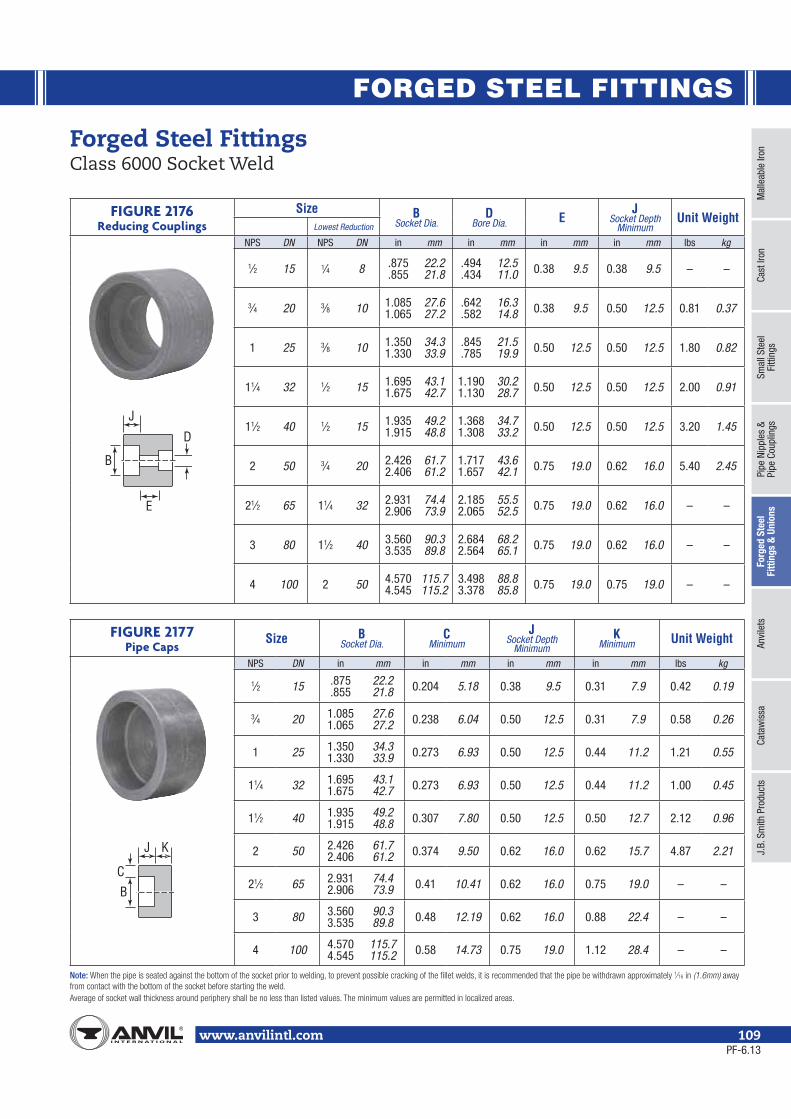
FORGED STEEL FITTINGS
Mal
leab
le Ir
onCa
st Ir
onSm
all S
teel
Fi
tting
sPi
pe N
ippl
es &
Pipe
Cou
plin
gsFo
rged
Ste
el
Fitti
ngs
& U
nion
sAn
vile
tsCa
taw
issa
J.B.
Sm
ith P
rodu
cts
www.anvilintl.com 109
Forged Steel Fittings Class 6000 Socket Weld
FIGURE 2176Reducing Couplings
Size BSocket Dia.
DBore Dia. E
JSocket Depth
MinimumUnit Weight
Lowest Reduction
NPS DN NPS DN in mm in mm in mm in mm lbs kg
1⁄2 15 1⁄4 8 .875.855
22.221.8
.494
.43412.511.0 0.38 9.5 0.38 9.5 – –
3⁄4 20 3⁄8 10 1.0851.065
27.627.2
.642
.58216.314.8 0.38 9.5 0.50 12.5 0.81 0.37
1 25 3⁄8 10 1.3501.330
34.333.9
.845
.78521.519.9 0.50 12.5 0.50 12.5 1.80 0.82
11⁄4 32 1⁄2 15 1.6951.675
43.142.7
1.1901.130
30.228.7 0.50 12.5 0.50 12.5 2.00 0.91
11⁄2 40 1⁄2 15 1.9351.915
49.248.8
1.3681.308
34.733.2 0.50 12.5 0.50 12.5 3.20 1.45
2 50 3⁄4 20 2.4262.406
61.761.2
1.7171.657
43.642.1 0.75 19.0 0.62 16.0 5.40 2.45
21⁄2 65 11⁄4 32 2.9312.906
74.473.9
2.1852.065
55.552.5 0.75 19.0 0.62 16.0 – –
3 80 11⁄2 40 3.5603.535
90.389.8
2.6842.564
68.265.1 0.75 19.0 0.62 16.0 – –
4 100 2 50 4.5704.545
115.7115.2
3.4983.378
88.885.8 0.75 19.0 0.75 19.0 – –
FIGURE 2177Pipe Caps
Size BSocket Dia.
CMinimum
JSocket Depth
MinimumK
Minimum Unit Weight
NPS DN in mm in mm in mm in mm lbs kg
1⁄2 15 .875.855
22.221.8 0.204 5.18 0.38 9.5 0.31 7.9 0.42 0.19
3⁄4 20 1.0851.065
27.627.2 0.238 6.04 0.50 12.5 0.31 7.9 0.58 0.26
1 25 1.3501.330
34.333.9 0.273 6.93 0.50 12.5 0.44 11.2 1.21 0.55
11⁄4 32 1.6951.675
43.142.7 0.273 6.93 0.50 12.5 0.44 11.2 1.00 0.45
11⁄2 40 1.9351.915
49.248.8 0.307 7.80 0.50 12.5 0.50 12.7 2.12 0.96
2 50 2.4262.406
61.761.2 0.374 9.50 0.62 16.0 0.62 15.7 4.87 2.21
21⁄2 65 2.9312.906
74.473.9 0.41 10.41 0.62 16.0 0.75 19.0 – –
3 80 3.5603.535
90.389.8 0.48 12.19 0.62 16.0 0.88 22.4 – –
4 100 4.5704.545
115.7115.2 0.58 14.73 0.75 19.0 1.12 28.4 – –
D
B
E
J
BC
J K
Note: ⁄ (1.6mm)
PF-6.13

FORGED STEEL FITTINGS
www.anvilintl.com110
Forged Steel Fittings High Pressure Plugs
FIGURE 2122Square Head Plugs
Size A B C Unit Weight
NPS DN in mm in mm in mm lbs kg1⁄8 6 0.38 10 0.25 6 0.28 7 0.02 0.011⁄4 8 0.44 11 0.25 6 0.38 10 0.03 0.013⁄8 10 0.50 13 0.31 8 0.44 11 0.06 0.031⁄2 15 0.56 14 0.38 10 0.56 14 0.10 0.053⁄4 20 0.62 16 0.44 11 0.62 16 0.18 0.081 25 0.75 19 0.50 13 0.81 21 0.38 0.17
11⁄4 32 0.81 21 0.56 14 0.94 24 0.62 0.2811⁄2 40 0.81 21 0.62 16 1.12 28 0.88 0.402 50 0.88 22 0.69 18 1.31 32 1.40 0.63
21⁄2 65 1.06 27 0.75 19 1.50 36 2.20 1.003 80 1.12 28 0.81 21 1.69 41 3.40 1.544 100 1.25 32 1.00 25 2.50 65 8.50 3.85
FIGURE 2142Hex Head Plugs
Size A FAcross Flats H Unit Weight
NPS DN in mm in mm in mm lbs kg1⁄8 6 0.38 10 0.44 11 0.25 6 0.03 0.011⁄4 8 0.44 11 0.62 16 0.25 6 0.05 0.023⁄8 10 0.50 13 0.69 18 0.31 8 0.09 0.041⁄2 15 0.56 14 0.88 22 0.31 8 0.13 0.063⁄4 20 0.62 16 1.06 27 0.38 10 0.27 0.121 25 0.75 19 1.38 36 0.38 10 0.48 0.22
11⁄4 32 0.81 21 1.75 46 0.56 14 0.94 0.4311⁄2 40 0.81 21 2.00 50 0.62 16 1.20 0.542 50 0.88 22 2.50 65 0.69 18 2.40 1.09
21⁄2 65 1.06 27 3.00 75 0.75 19 3.80 1.723 80 1.12 28 3.50 90 0.81 21 4.80 2.184 100 1.25 32 4.62 115 1.00 25 13.00 5.90
FIGURE 2121Round Head Plugs
Size A D E Unit Weight
NPS DN in mm in mm in mm lbs kg1⁄8 6 0.38 10 1.38 35 0.41 10 0.05 0.021⁄4 8 0.44 11 1.62 41 0.53 13 0.10 0.053⁄8 10 0.50 13 1.62 41 0.69 18 0.16 0.071⁄2 15 0.56 14 1.75 44 0.84 21 0.28 0.133⁄4 20 0.62 16 1.75 44 1.06 27 0.42 0.191 25 0.75 19 2.00 51 1.31 33 0.82 0.37
11⁄4 32 0.81 21 2.00 51 1.69 43 1.20 0.5411⁄2 40 0.81 21 2.00 51 1.91 49 1.50 0.682 50 0.88 22 2.50 64 2.38 60 3.20 1.45
21⁄2 65 1.06 27 2.75 70 2.88 73 – –3 80 1.12 28 2.75 70 3.50 89 – –4 100 1.25 32 3.00 76 4.50 114 – –
Note:
Amin
BminCmin
A
HF
A
D
E
PF-6.13

FORGED STEEL FITTINGS
Mal
leab
le Ir
onCa
st Ir
onSm
all S
teel
Fi
tting
sPi
pe N
ippl
es &
Pipe
Cou
plin
gsFo
rged
Ste
el
Fitti
ngs
& U
nion
sAn
vile
tsCa
taw
issa
J.B.
Sm
ith P
rodu
cts
www.anvilintl.com 111
Forged Steel Fittings High Pressure Bushings
FIGURE 2139Hex Head Bushings
SizeA F G Unit Weight
Lowest Reduction
NPS DN NPS DN in mm in mm in mm lbs kg
1⁄4 8 1⁄8 6 0.44 11 0.62 16 0.12 3 0.02 0.01
3⁄8 10 1⁄8 6 0.50 13 0.69 18 0.16 4 0.03 0.01
1⁄2 15 1⁄8 6 0.56 14 0.88 22 0.19 5 0.06 0.03
3⁄4 20 1⁄8 6 0.62 16 1.06 27 0.22 6 0.11 0.05
1 25 1⁄8 6 0.75 19 1.38 36 0.25 6 0.20 0.09
11⁄4 32 1⁄8 6 0.81 21 1.75 46 0.28 7 0.40 0.18
11⁄2 40 1⁄4 8 0.81 21 2.00 50 0.31 8 0.50 0.23
2 50 1⁄4 8 0.88 22 2.50 65 0.34 9 0.85 0.39
21⁄2 65 1⁄2 15 1.06 27 3.00 75 0.38 10 1.20 0.54
3 80 1⁄2 15 1.12 28 3.50 90 0.41 10 2.60 1.18
4 100 11⁄2 40 1.25 32 4.62 115 0.50 13 7.00 3.17
FIGURE 2140Flush Bushings
SizeA Unit Weight
Lowest Reduction
NPS DN NPS DN in mm lbs kg
1⁄4 8 1⁄8 6 0.44 11 0.03 0.01
3⁄8 10 1⁄8 6 0.50 13 0.03 0.01
1⁄2 15 1⁄8 6 0.56 14 0.06 0.03
3⁄4 20 1⁄8 6 0.62 16 0.09 0.04
1 25 1⁄8 6 0.75 19 0.12 0.05
11⁄4 32 1⁄8 6 0.81 21 0.15 0.07
11⁄2 40 1⁄4 8 0.81 21 0.20 0.09
2 50 1⁄4 8 0.88 22 0.35 0.16
Note:
A
G
F
A
PF-6.13

FORGED STEEL FITTINGS
www.anvilintl.com112
Forged Steel FittingsSocket-Weld Reducer Inserts
(1.6 mm)
CLASS 3000For use with Schedule 40 and 80 Pipe
Size Class 3000 – For use with Schedule 40 and 80 PipeSD B Type A D C Min. K SL RL Min. Unit Weight
NPS DN NPS DN in mm in mm in mm in mm in mm in mm lbs kg
1⁄2 151⁄4 8 1 0.81 20.57 0.364 9.25 0.149 3.78 0.438 11.11 0.62 15.75 – –
0.18 0.083⁄8 10 1 0.81 20.57 0.493 12.52 0.158 4.00 0.438 11.11 0.62 15.75 – –
3⁄4 20
1⁄4 8 2 0.69 17.53 0.364 9.25 0.149 3.78 0.375 9.53 – – 1.06 270.25 0.113⁄8 10 2 0.62 15.75 0.493 12.52 0.158 4.00 0.438 11.11 – – 1.06 27
1⁄2 15 1 0.88 22.35 0.622 15.80 0.184 4.67 0.438 11.11 0.69 17.53 – –
1 25
1⁄4 8 2 0.75 19.05 0.364 9.25 0.149 3.78 0.375 9.53 – – 1.12 28
0.35 0.163⁄8 10 2 0.69 17.53 0.493 12.52 0.158 4.00 0.438 11.11 – – 1.12 281⁄2 15 2 0.62 15.75 0.622 15.80 0.184 4.67 0.438 11.13 – – 1.12 283⁄4 20 1 0.94 23.88 0.824 20.93 0.193 4.90 0.563 14.29 0.75 19.05 – –
11⁄4 32
1⁄4 8 2 0.88 22.35 0.364 9.25 0.149 3.78 0.375 9.53 – – 1.25 32
0.35 0.25
3⁄8 10 2 0.81 20.57 0.493 12.52 0.158 4.00 0.438 11.11 – – 1.25 321⁄2 15 2 0.75 19.05 0.622 15.80 0.184 4.67 0.438 11.13 – – 1.25 323⁄4 20 2 0.69 17.53 0.824 20.93 0.193 4.90 0.563 14.29 – – 1.25 321 25 1 1.00 25.40 1.049 26.65 0.224 5.69 0.563 14.29 0.81 20.57 – –
11⁄2 40
3⁄8 10 2 0.88 22.35 0.493 12.52 0.158 4.00 0.438 11.11 – – 1.31 33
0.62 0.28
1⁄2 15 2 0.81 20.57 0.622 15.80 0.184 4.67 0.438 11.13 – – 1.31 333⁄4 20 2 0.75 19.05 0.824 20.93 0.193 4.90 0.563 14.29 – – 1.31 331 25 2 0.69 17.53 1.049 26.65 0.224 5.69 0.500 12.70 – – 1.31 33
11⁄4 32 1 1.12 28.45 1.380 35.05 0.239 6.00 0.563 14.29 0.88 22.35 – –
2 50
1⁄2 15 2 1.00 25.40 0.622 15.80 0.184 4.67 0.438 11.13 – – 1.50 38
1.50 0.68
3⁄4 20 2 0.94 23.88 0.824 20.93 0.193 4.90 0.563 14.29 – – 1.50 381 25 2 0.88 22.35 1.049 26.65 0.224 5.69 0.563 14.30 – – 1.50 38
11⁄4 32 2 0.81 20.57 1.380 35.05 0.239 6.00 0.563 14.30 – – 1.50 3811⁄2 40 1 1.25 31.75 1.610 40.64 0.250 6.35 0.563 14.29 1.00 25.40 – –
21⁄2 65
3⁄4 20 – 1.56 39.62 0.824 20.93 0.193 4.90 0.562 14.27 – – 2.12 54
3.00 1.361 25 – 1.50 38.10 1.049 26.65 0.224 5.69 0.562 14.27 – – 2.12 54
11⁄4 32 – 1.44 36.58 1.380 35.05 0.239 6.00 0.562 14.27 – – 2.12 5411⁄2 40 – 1.38 35.05 1.610 40.64 0.250 6.35 0.562 14.27 – – 2.12 542 50 – 1.81 46.00 2.067 52.50 0.273 6.93 0.688 17.48 1.50 38.10 – –
3 80
1 25 – 1.25 31.75 1.049 26.65 0.224 5.69 0.562 14.27 – – 1.87 47
4.40 2.0011⁄4 32 – 1.19 30.23 1.380 35.05 0.239 6.00 0.562 14.27 – – 1.87 4711⁄2 40 – 1.12 28.45 1.610 40.64 0.250 6.35 0.562 14.27 – – 1.87 472 50 – 1.00 25.40 2.067 52.50 0.273 6.93 0.688 17.48 – – 1.87 47
21⁄2 65 – 1.50 38.10 2.469 62.71 0.345 8.76 0.688 17.48 1.25 31.75 – –
SD D
A K
CSL 45
B
C
Type 1 - Reducer InsertFig. 2159
SD D
A K
C
RL
B
Type 2 - Reducer InsertFig. 2179
PF-6.13

FORGED STEEL FITTINGS
Mal
leab
le Ir
onCa
st Ir
onSm
all S
teel
Fi
tting
sPi
pe N
ippl
es &
Pipe
Cou
plin
gsFo
rged
Ste
el
Fitti
ngs
& U
nion
sAn
vile
tsCa
taw
issa
J.B.
Sm
ith P
rodu
cts
www.anvilintl.com 113
Forged Steel FittingsSocket-Weld Reducer Inserts
CLASS 6000For use with Schedule 160 Pipe
Size Class 6000 – For use with Schedule 160 PipeSD B Type A D C Min. K SL RL Min. Unit Weight
NPS DN NPS DN in mm in mm in mm in mm in mm in mm lbs kg
3⁄4 20
1⁄4 8 2 0.88 22.35 0.250 6.35 0.181 4.60 0.375 9.53 – – 1.26 32
0.81 0.373⁄8 10 1 0.88 22.35 0.359 9.12 0.198 5.00 0.438 11.11 0.75 19.05 – –
1⁄2 15 1 1.00 25.40 0.464 11.79 0.235 6.00 0.438 11.11 0.75 19.05 – –
1 25
1⁄4 8 2 0.94 23.88 0.250 6.35 0.181 4.60 0.375 9.53 – – 1.31 33
1.80 0.82
3⁄8 10 2 0.88 22.35 0.359 9.12 0.198 5.00 0.438 11.13 – – 1.31 33
1⁄2 15 1 1.12 28.45 0.464 11.79 0.235 6.00 0.438 11.11 0.81 20.57 – –
3⁄4 20 1 1.12 28.45 0.612 15.49 0.274 6.96 0.563 14.29 0.81 20.57 – –
11⁄4 32
1⁄4 8 2 1.00 25.40 0.250 6.35 0.181 4.60 0.375 9.53 – – 1.37 35
2.00 0.91
3⁄8 10 2 0.94 23.88 0.359 9.12 0.198 5.00 0.438 11.11 – – 1.37 35
1⁄2 15 2 0.88 22.35 0.464 11.79 0.235 6.00 0.438 11.13 – – 1.37 35
3⁄4 20 2 0.81 20.57 0.612 15.49 0.274 6.96 0.563 14.29 – – 1.37 35
1 25 1 1.19 30.23 0.815 20.70 0.312 7.92 0.563 14.29 0.88 22.35 – –
11⁄2 40
3⁄8 10 2 1.12 28.45 0.359 9.12 0.198 5.00 0.438 11.11 – – 1.56 40
3.20 1.45
1⁄2 15 2 1.06 26.92 0.464 11.79 0.235 6.00 0.438 11.13 – – 1.56 40
3⁄4 20 2 1.00 25.40 0.612 15.49 0.274 6.96 0.563 14.29 – – 1.56 40
1 25 1 1.15 29.21 0.815 20.70 0.312 7.92 0.563 14.29 1.00 25.40 – –
11⁄4 32 1 1.38 35.05 1.160 29.46 0.312 7.92 0.563 14.29 1.00 25.40 – –
2 50
1⁄2 15 2 1.12 28.45 0.464 11.79 0.235 6.00 0.438 11.13 – – 1.62 41
5.40 2.45
3⁄4 20 2 1.06 26.92 0.612 15.49 0.274 6.96 0.562 14.3 – – 1.62 41
1 25 2 1.00 25.40 0.815 20.70 0.312 7.92 0.562 14.3 – – 1.62 41
11⁄4 32 2 0.94 23.88 1.160 29.46 0.312 7.92 0.562 14.3 – – 1.62 41
SD D
A K
CSL 45
B
C
Type 1 - Reducer InsertFig. 2159
SD D
A K
C
RL
B
Type 2 - Reducer InsertFig. 2179
PF-6.13
(1.6 mm)

FORGED STEEL FITTINGS
www.anvilintl.com114
Forged Steel UnionsClass 3000 Threaded & Socket-Weld
FIGURE 2125: Threaded Union
Size A B C* D E F Unit WeightNPS DN in mm in mm in mm in mm in mm in mm lbs kg
1⁄4 8 111⁄16 43 131⁄64 38 53⁄64 21 25⁄32 20 7⁄16 11 0.555 0.575
14 15 0.30 0.14
3⁄8 10 127⁄32 47 111⁄16 43 1 25 31⁄32 25 7⁄16 11 0.690 0.710
18 18 0.50 0.23
1⁄2 15 2 51 115⁄16 49 13⁄16 30 13⁄32 28 7⁄16 11 0.855 0.875
22 22 0.70 0.32
3⁄4 20 25⁄16 59 23⁄8 60 115⁄32 37 15⁄32 29 9⁄16 14 1.065 1.085
27 28 1.20 0.54
1 25 27⁄16 62 225⁄32 71 125⁄32 45 13⁄8 35 9⁄16 14 1.330 1.350
34 34 1.70 0.77
11⁄4 32 27⁄8 73 323⁄64 85 27⁄32 686 145⁄64 43 9⁄16 14 1.675 1.695
43 43 2.50 1.13
11⁄2 40 3 76 323⁄64 85 235⁄64 65 17⁄8 48 9⁄16 14 1.915 1.935
49 49 3.30 1.50
2 50 31⁄2 89 427⁄64 112 31⁄16 78 21⁄16 52 11⁄16 17 2.406 2.426
61 62 5.30 2.40
21⁄2 65 41⁄4 108 515⁄64 133 39⁄16 90 23⁄8 60 7⁄8 22 2.906 2.931
74 74 8.60 3.90
3 80 47⁄16 113 65⁄32 156 49⁄32 109 27⁄16 62 1 25 3.535 3.560
90 90 12.70 5.76
FIGURE 2126: Socket-Weld Union
Size A B C* D E F Unit WeightNPS DN in mm in mm in mm in mm in mm in mm lbs kg
1⁄4 8 111⁄16 43 131⁄64 38 53⁄64 21 25⁄32 20 7⁄16 11 0.555 0.575
14 15 0.30 0.14
3⁄8 10 127⁄32 47 111⁄16 43 1 25 31⁄32 25 7⁄16 11 0.690 0.710
18 18 0.50 0.23
1⁄2 15 2 51 115⁄16 49 13⁄16 30 13⁄32 28 7⁄16 11 0.855 0.875
22 22 0.70 0.32
3⁄4 20 25⁄16 59 23⁄8 60 115⁄32 37 15⁄32 29 9⁄16 14 1.065 1.085
27 28 1.20 0.54
1 25 27⁄16 62 225⁄32 71 125⁄32 45 13⁄8 35 9⁄16 14 1.330 1.350
34 34 1.70 0.77
11⁄4 32 27⁄8 73 323⁄64 85 27⁄32 686 145⁄64 43 9⁄16 14 1.675 1.695
43 43 2.50 1.13
11⁄2 40 3 76 323⁄64 85 235⁄64 65 17⁄8 48 9⁄16 14 1.915 1.935
49 49 3.30 1.50
2 50 31⁄2 89 427⁄64 112 31⁄16 78 21⁄16 52 11⁄16 17 2.406 2.426
61 62 5.30 2.40
21⁄2 65 41⁄4 108 515⁄64 133 39⁄16 90 23⁄8 60 7⁄8 22 2.906 2.931
74 74 8.60 3.90
3 80 47⁄16 113 65⁄32 156 49⁄32 109 27⁄16 62 1 25 3.535 3.560
90 90 12.70 5.76
⁄ (65 DN) (80 DN) (50 DN)
A D
E
FC
BSocket-Weld
A
CB
Threaded
PF-11.13

FORGED STEEL FITTINGS
Mal
leab
le Ir
onCa
st Ir
onSm
all S
teel
Fi
tting
sPi
pe N
ippl
es &
Pipe
Cou
plin
gsFo
rged
Ste
el
Fitti
ngs
& U
nion
sAn
vile
tsCa
taw
issa
J.B.
Sm
ith P
rodu
cts
www.anvilintl.com 115
Forged Steel UnionsClass 6000 Threaded & Socket-Weld
FIGURE 2127: Threaded Union
Size A B C* D E F Unit WeightNPS DN in mm in mm in mm in mm in mm in mm lbs kg
1⁄4 8 127⁄32 47 111⁄16 43 1 25 31⁄32 25 7⁄16 11 0.555 0.575
14 15 0.60 0.27
3⁄8 10 2 51 115⁄16 49 13⁄16 30 13⁄32 28 7⁄16 11 0.690 0.710
18 18 0.80 0.36
1⁄2 15 25⁄16 59 23⁄8 60 115⁄32 37 15⁄32 29 9⁄16 14 0.855 0.875
22 22 1.40 0.63
3⁄4 20 27⁄16 62 225⁄32 71 125⁄32 45 13⁄8 35 9⁄16 14 1.065 1.085
27 28 2.00 0.91
1 25 27⁄8 73 323⁄64 85 27⁄32 686 145⁄64 43 9⁄16 14 1.330 1.350
34 34 3.10 1.41
11⁄4 32 3 76 323⁄32 94 235⁄64 65 17⁄8 48 9⁄16 14 1.675 1.695
43 43 5.90 2.68
11⁄2 40 31⁄2 89 427⁄64 112 31⁄16 78 21⁄16 52 11⁄16 17 1.915 1.935
49 49 6.60 2.99
2 50 41⁄8 105 515⁄64 133 39⁄16 90 23⁄8 60 7⁄8 22 2.406 2.426
61 62 10.50 4.76
FIGURE 2128: Socket-Weld Union
Size A B C* D E F Unit WeightNPS DN in mm in mm in mm in mm in mm in mm lbs kg
1⁄4 8 127⁄32 47 111⁄16 43 1 25 31⁄32 25 7⁄16 11 0.555 0.575
14 15 0.60 0.27
3⁄8 10 2 51 115⁄16 49 13⁄16 30 13⁄32 28 7⁄16 11 0.690 0.710
18 18 0.80 0.36
1⁄2 15 25⁄16 59 23⁄8 60 115⁄32 37 15⁄32 29 9⁄16 14 0.855 0.875
22 22 1.40 0.63
3⁄4 20 27⁄16 62 225⁄32 71 125⁄32 45 13⁄8 35 9⁄16 14 1.065 1.085
27 28 2.00 0.91
1 25 27⁄8 73 323⁄64 85 27⁄32 686 145⁄64 43 9⁄16 14 1.330 1.350
34 34 3.10 1.41
11⁄4 32 3 76 323⁄32 94 235⁄64 65 17⁄8 48 9⁄16 14 1.675 1.695
43 43 5.90 2.68
11⁄2 40 31⁄2 89 427⁄64 112 31⁄16 78 21⁄16 52 11⁄16 17 1.915 1.935
49 49 6.60 2.99
2 50 41⁄8 105 515⁄64 133 39⁄16 90 23⁄8 60 7⁄8 22 2.406 2.426
61 62 10.50 4.76
⁄ (65 DN) (80 DN) (50 DN)
A D
E
FC
BSocket-Weld
A
CB
Threaded
PF-6.13

ANVILETS
www.anvilintl.com116
Anvil Anvilets provide a strong branch pipe connection, considerably stronger than a welded pipe-to-pipe connection. Consequently, with good welding procedures, Anvil Anvilets offer greater resistance to distortion and bursting.
Anvil Anvilets readily and economically permit the adding of branch connectors to existing piping installations, eliminating the relatively higher cost of cutting or disassembly and re-assembly required for the installation of tees.
Anvil Anvilets of the same outlet size as a header or run pipe size (i.e. “Full Size” Anvilets) are so proportioned that the (ellipticallyshaped) hole in the header pipe has the minimum weakening or distortion effect, and yet provides good fluid flow characteristics.
SpecificationsChemical and physical properties are rigidly controlled to ensure consistently high quality. Physical and chemical test reports are available on request. Traceability of individual Anvilets can be established through the heat code of each fitting.
Anvil Anvilets meet the requirements of MSS standard SP-97. They are forged from steel which complies with ASTM A105.
Threaded Anvilets - conform with ASME B1.20.1.
Socket-Weld Anvilets - dimensions conform with ASME B16.11.
Buttweld Anvilets - ends conform with ASME B16.25.
Reinforcement RequirementsASME B31.1 Power Piping CodeASME B31.3 Refinery Code
Forging MarkingsAnvil Anvilets are clearly marked with the following:
• Outlet size
• Range of run pipe sizes that the Anvilet will fit
• The weight, schedule number, or pressure class
• The material specification
• Steel heat code identification
Installation NoteAnvil Anvilets are designed to have no more than a 1⁄16" gap (1.6mm) between the base or skirt of the Anvilet when it is seated directly upon the appropriate run pipe. However, it is recommended that the skirt of Anvilets be held slightly above the run pipe and tack welded to provide a small continuous root gap between the skirt and run pipe before completing the all-around welding beads or fillet.
SpecialsYour local Anvil Branch will be more than happy to assist you with specially machined outlets and those made of alloy material.
Pressure Temperature RatingsMSS standard Practice SP-97 gives the following correlation between fitting pressure class and pipe schedule number/wall thickness designation for calculation of pressure-temperature ratings:
Branch Connection
Type
Pressure Class of Fitting
Branch Connection Size
Pipe Wall for Rating
BasisNPS DN
ButtweldSTD 1⁄8 - 24 6 - 600 STD
XS/XH 1⁄8 - 24 6 - 600 XS/XHSCH 160 1⁄2- 6 15 - 150 SCH 160
Threaded3,000 1⁄4 - 4 8 - 100 XS/XH6,000 1⁄2- 2 15 - 50 SCH 160
Socket-Welding3,000 1⁄2- 2 15 - 50 XS/XH6,000 1⁄2- 2 15 - 50 SCH 160
The maximum allowable pressure of a fitting is computed in accordance with the applicable piping code or regulation for straight seamless header (run) pipe or for material of equivalent composition and mechanical properties to the fitting. Any corrosion or mechanical allowances and any reduction in allowable stress due to temperature or other service conditions, must be applied to the pipe and fitting alike.
Forged Steel Anvilets
PF-6.13

ANVILETS
Mal
leab
le Ir
onCa
st Ir
onSm
all S
teel
Fi
tting
sPi
pe N
ippl
es &
Pipe
Cou
plin
gsFo
rged
Ste
elFi
tting
s &
Unio
nsAn
vile
tsCa
taw
issa
J.B.
Sm
ith P
rodu
cts
www.anvilintl.com 117
Universal Forged Steel Anvilets Standard & Extra Strong Buttweld
Each outlet size listed is available to fit any run curvature. BW Ends per B16.9 and B16.25. Design per MSS-SP-97.RUN PIPE SIZES Outlet sizes 6" and less fit a number of run pipe sizes, and the fittings are marked accordingly. See page 121 for run pipe size combination table(s).SCHEDULES Standard Weight Fittings are the same as schedule 40 fittings through 10". A schedule 40 butt-welded Universal Forged Steel Anvilet for sizes 12" and
larger is available. Dimensions and prices on application. Extra Strong Fittings are the same as schedule 80 fittings through 8". A schedule 80 butt-welded Universal Forged Steel Anvilet for sizes 10" and larger is available. Dimensions and prices on application. Pipe schedule numbers and weight designations are in accordance with ASME B36.10.
FLATS Flat butt-welded Universal Forged Steel Anvilet fittings for use on welding caps, elliptical heads and flat surfaces is available.
BUTTWELD Standard
Outlet SizeDimensions
Unit WeightA B C
NPS DN in mm in mm in mm lbs kg1⁄8 6 5⁄8 16 1 25 0.625 16 0.10 0.051⁄4 8 5⁄8 16 1 25 0.625 16 0.10 0.053⁄8 10 3⁄4 19 1 25 0.493 13 0.10 0.051⁄2 15 3⁄4 19 11⁄8 29 0.622 16 0.12 0.053⁄4 20 7⁄8 22 11⁄2 38 0.824 21 0.22 0.101 25 11⁄16 27 113⁄16 46 1.062 27 0.32 0.15
11⁄4 32 11⁄4 32 21⁄4 57 1.380 35 0.64 0.2911⁄2 40 15⁄16 33 29⁄16 65 1.625 41 0.78 0.352 50 11⁄2 38 35⁄16 84 2.313 59 1.14 0.52
21⁄2 65 15⁄8 41 321⁄32 93 2.500 64 1.94 0.883 80 13⁄4 44 49⁄32 109 3.125 79 2.60 1.184 100 2 51 53⁄8 137 4.145 105 4.12 1.876 150 23⁄8 60 721⁄32 194 6.112 155 11.00 4.998 200 23⁄4 70 103⁄8 264 8.688 221 28.00 12.70
10 250 31⁄16 78 129⁄16 319 10.813 275 39.00 17.6912 300 33⁄8 86 147⁄8 378 12.813 325 65.00 29.4814 350 31⁄2 89 161⁄8 410 14.063 357 70.00 31.7516 400 311⁄16 94 181⁄4 464 16.063 408 92.00 41.7318 450 41⁄16 103 203⁄4 527 18.625 473 125.00 56.7020 500 45⁄8 117 231⁄16 586 20.063 510 175.00 79.3824 600 53⁄8 137 277⁄8 708 25.125 638 280.00 127.01
A
C
ROOTGAP
B
C
OUTLETBRANCH
RUN PIPE
BUTTWELD Extra Strong
Outlet SizeDimensions
Unit WeightA B C
NPS DN in mm in mm in mm lbs kg1⁄8 6 5⁄8 16 1 25 0.625 16 0.10 0.051⁄4 8 5⁄8 16 1 25 0.625 16 0.10 0.053⁄8 10 3⁄4 19 1 25 0.423 11 0.10 0.051⁄2 15 3⁄4 19 11⁄8 29 0.546 14 0.12 0.053⁄4 20 7⁄8 22 11⁄2 38 0.742 19 0.18 0.081 25 11⁄16 27 213⁄16 71 1.062 27 0.36 0.16
11⁄4 32 11⁄4 32 21⁄4 57 1.278 32 0.55 0.2511⁄2 40 15⁄16 33 29⁄16 65 1.625 41 0.68 0.312 50 11⁄2 38 35⁄16 84 2.313 59 1.24 0.56
21⁄2 65 15⁄8 41 321⁄32 93 2.500 64 2.26 1.023 80 13⁄4 44 49⁄32 109 3.125 79 2.84 1.294 100 2 51 53⁄8 137 4.145 105 4.56 2.076 150 31⁄16 78 723⁄32 196 5.800 147 15.00 6.808 200 37⁄8 98 105⁄8 270 8.688 221 32.00 14.51
10 250 31⁄2 89 127⁄8 327 10.738 273 46.00 20.8712 300 315⁄16 100 153⁄16 386 13.000 330 61.00 27.6714 350 41⁄8 105 1611⁄16 424 14.313 364 75.00 34.0216 400 47⁄16 113 187⁄8 479 16.500 419 115.00 52.1618 450 411⁄16 119 211⁄8 537 18.625 473 130.00 58.9720 500 5 127 233⁄8 594 20.813 529 187.00 84.8224 600 51⁄2 140 277⁄8 708 25.125 638 316.00 143.34
PF-6.13

ANVILETS
www.anvilintl.com118
Universal Forged Steel Anvilets XXS, SCH. 160 Buttweld
A
C
ROOTGAP
B
C
OUTLETBRANCH
RUN PIPE
BUTTWELDXXS, Sch. 160
Outlet SizeDimensions
Unit WeightA B C
NPS DN in mm in mm in mm lbs kg1⁄2 15 11⁄8 29 13⁄8 35 0.563 14 0.25 0.113⁄4 20 11⁄4 32 13⁄4 44 0.750 19 0.70 0.321 25 11⁄2 38 2 51 1.000 25 0.85 0.39
11⁄4 32 13⁄4 44 27⁄16 62 1.313 33 1.25 0.5711⁄2 40 2 51 23⁄4 70 1.500 38 1.75 0.792 50 23⁄16 56 33⁄16 81 1.688 43 2.15 0.98
21⁄2 65 27⁄16 62 313⁄16 97 2.125 54 3.40 1.543 80 27⁄8 73 43⁄4 121 2.875 73 6.30 2.864 100 35⁄16 84 6 152 3.875 98 4.56 4.76
Each outlet size listed is available to fit any run curvature. BW Ends per B16.9 and B16.25. Design per MSS-SP-97.RUN PIPE SIZES Outlet sizes 6" and less fit a number of run pipe sizes, and the fittings are marked accordingly. See page 121 for run pipe size combination table(s).SCHEDULES Standard Weight Fittings are the same as schedule 40 fittings through 10". A schedule 40 butt-welded Universal Forged Steel Anvilet for sizes 12" and
larger is available. Dimensions and prices on application. Extra Strong Fittings are the same as schedule 80 fittings through 8". A schedule 80 butt-welded Universal Forged Steel Anvilet for sizes 10" and larger is available. Dimensions and prices on application. Pipe schedule numbers and weight designations are in accordance with ASME B36.10.
FLATS Flat butt-welded Universal Forged Steel Anvilet fittings for use on welding caps, elliptical heads and flat surfaces is available.
PF-6.13

ANVILETS
Mal
leab
le Ir
onCa
st Ir
onSm
all S
teel
Fi
tting
sPi
pe N
ippl
es &
Pipe
Cou
plin
gsFo
rged
Ste
elFi
tting
s &
Unio
nsAn
vile
tsCa
taw
issa
J.B.
Sm
ith P
rodu
cts
www.anvilintl.com 119
Universal Forged Steel Anvilets Class 3000 & 6000 Threaded
Each outlet size listed is available to fit any run curvature. Threaded ends are in accordance with ANSI/ASME B1.20.1. Design per MSS-SP-97.
RUN PIPE SIZES Outlet sizes noted above fit a number of run pipe sizes, and the fittings are marked accordingly. See page 121 for run pipe size combination table(s).
FLATS A flat Threaded Universal Forged Steel Anvilet for use on welding caps, elliptical heads and flat surfaces is available.
THREADED Class 3000
Outlet SizeDimensions
Unit WeightA B C
NPS DN in mm in mm in mm lbs kg1⁄8 6 3⁄4 19 1 25 0.625 16 0.10 0.051⁄4 8 3⁄4 19 11⁄16 27 0.437 11 0.14 0.063⁄8 10 13⁄16 21 11⁄16 27 0.578 15 0.14 0.061⁄2 15 1 25 115⁄32 37 0.718 18 0.28 0.133⁄4 20 11⁄16 27 145⁄64 43 0.922 23 0.39 0.18
1 25 15⁄16 33 23⁄32 53 1.156 29 0.73 0.33
11⁄4 32 15⁄16 33 217⁄32 64 1.500 38 0.96 0.44
11⁄2 40 13⁄8 35 225⁄32 71 1.734 44 1.12 0.51
2 50 11⁄2 38 35⁄16 84 2.218 56 1.66 0.75
21⁄2 65 113⁄16 46 329⁄32 99 2.625 67 2.73 1.24
3 80 2 51 421⁄32 118 3.250 83 3.88 1.76
4 100 21⁄4 57 513⁄16 148 4.250 108 6.18 2.80
THREADED Class 6000
Outlet SizeDimensions
Unit WeightA B C
NPS DN in mm in mm in mm lbs kg1⁄2 15 11⁄4 32 13⁄4 44 0.718 19 0.28 0.133⁄4 20 17⁄16 37 21⁄16 52 0.922 24 0.39 0.18
1 25 19⁄16 40 217⁄32 64 1.156 31 0.73 0.33
11⁄4 32 15⁄8 41 21⁄2 64 1.500 40 0.96 0.44
11⁄2 40 111⁄16 43 35⁄16 84 1.734 46 1.12 0.51
2 50 21⁄16 52 331⁄32 101 2.218 59 1.66 0.75
A
C
B
C
OUTLETBRANCH
RUNPIPE
PF-6.13

ANVILETS
www.anvilintl.com120
Universal Forged Steel Anvilets Standard & Extra Strong Socket-Weld
Each outlet size listed is available to fit any run curvature. Socket dimensions are in accordance with ASME B16.11. Design per MSS-SP-97.
RUN PIPE SIZES Outlet sizes noted above fit a number of run pipe sizes, and the fittings are marked accordingly. See page 121 for run pipe size combination table(s).
FLATS A flat Socket-welded Universal Forged Steel Anvilet for use on welding caps, elliptical heads and flat surfaces is available.
SOCKET-WELD Class 3000
OutletSize
Dimensions UnitWeightA B C E
NPS DN in mm in mm in mm in mm lbs kg1⁄8 6 3⁄4 19 1 25 0.625 16 9⁄32 7 0.10 0.051⁄4 8 3⁄4 19 1 25 0.364 9 3⁄8 10 0.14 0.063⁄8 10 13⁄16 21 11⁄16 27 0.493 13 7⁄16 11 0.14 0.061⁄2 15 1 25 115⁄32 37 0.622 16 9⁄16 14 0.28 0.133⁄4 20 11⁄16 27 145⁄64 43 0.824 21 9⁄16 14 0.39 0.18
1 25 15⁄16 33 23⁄32 53 1.049 27 25⁄32 20 0.73 0.33
11⁄4 32 15⁄16 33 217⁄32 64 1.380 35 23⁄32 18 0.96 0.44
11⁄2 40 13⁄8 35 225⁄32 71 1.610 41 3⁄4 19 1.12 0.51
2 50 11⁄2 38 35⁄16 84 2.067 53 13⁄16 21 1.66 0.75
21⁄2 65 113⁄16 46 329⁄32 99 2.469 63 3⁄4 19 2.73 1.24
3 80 2 51 421⁄32 118 3.068 78 15⁄16 24 3.88 1.76
4 100 21⁄4 57 513⁄16 148 4.026 102 11⁄16 27 6.60 2.99
SOCKET-WELD Class 6000
OutletSize
Dimensions UnitWeightA B C E
NPS DN in mm in mm in mm in mm lbs kg1⁄2 15 11⁄4 32 13⁄4 44 0.464 12 13⁄16 21 0.28 0.133⁄4 20 17⁄16 37 21⁄16 52 0.612 16 15⁄16 24 0.39 0.18
1 25 19⁄16 40 217⁄32 64 0.815 21 11⁄32 26 0.73 0.33
11⁄4 32 15⁄8 41 21⁄2 64 1.160 29 11⁄32 26 0.96 0.44
11⁄2 40 111⁄16 43 35⁄16 84 1.338 34 11⁄16 27 1.63 0.74
2 50 21⁄16 52 331⁄32 101 1.687 43 13⁄8 35 1.66 0.75
A
C
B
ROOTGAP
C
E
OUTLETBRANCH
RUN PIPE
PF-6.13

ANVILETS
Mal
leab
le Ir
onCa
st Ir
onSm
all S
teel
Fi
tting
sPi
pe N
ippl
es &
Pipe
Cou
plin
gsFo
rged
Ste
elFi
tting
s &
Unio
nsAn
vile
tsCa
taw
issa
J.B.
Sm
ith P
rodu
cts
www.anvilintl.com 121
Engineering SpecificationsUniversal Forged Steel Anvilets Run Size Combinations
Outlet Size (in)
Butt
wel
dSt
anda
rd
1⁄4 3⁄8 1⁄2 3⁄4 1 11⁄4 11⁄2 2 21⁄2 3 4 61⁄4 1⁄2 – 3⁄8 1 – 1⁄2 2 – 3⁄4 1 11⁄4 11⁄2 2 21⁄2 3 4 6
36 – 3⁄8 36 – 3⁄4 36 – 11⁄4 36 – 21⁄2 11⁄2 – 11⁄4 2 – 11⁄2 31⁄2 – 2 3 – 21⁄2 4 – 3 4 – 31⁄2 6 – 5 836 – 2 6 – 21⁄2 36 – 4 6 – 31⁄2 10 – 5 6 – 5 10 – 8 10
36 – 8 36 – 8 36 – 12 14 – 8 20 – 12 14 – 1236 – 16 36 – 22 18 – 16
24 – 2034 – 2642 – 36
Butt
wel
dEx
tra
Stro
ng
1⁄4 3⁄8 1⁄2 3⁄4 1 11⁄4 11⁄2 2 21⁄2 3 4 636 – 1⁄4 3⁄8 3⁄4 – 1⁄2 11⁄2 – 3⁄4 1 2 – 11⁄4 11⁄2 2 2 1⁄2 3 4 6
36 – 1⁄2 36 – 1 36 – 2 11⁄2 – 11⁄4 5 – 21⁄2 31⁄2 – 2 3 – 21⁄2 4 – 3 4 – 31⁄2 6 – 5 836 – 2 36 – 6 36 – 4 6 – 31⁄2 10 – 5 6 – 5 10 – 8 10
36 – 8 36 – 12 14 – 8 20 – 12 14 – 1236 – 1 36 – 22 18 – 16
24 – 2034 – 2642 – 36
Outlet Size (in)
Thre
aded
Cla
ss 3
000
1⁄4 3⁄8 1⁄2 3⁄4 1 11⁄4 11⁄2 2 21⁄2 3 43⁄8 – 1⁄4 1 – 3⁄8 1⁄2 11⁄4 – 3⁄4 1 11⁄2 – 11⁄4 11⁄2 2 21⁄2 3 436 – 1⁄2 36 – 11⁄4 36 – 3⁄4 36 – 11⁄2 21⁄2 – 11⁄4 31⁄2 – 2 21⁄2 – 2 31⁄2 – 21⁄2 31⁄2 – 3 5 – 31⁄2 6 – 5
36 – 3 36 – 4 5 – 3 6 – 4 6 – 4 14 – 6 10 – 836 – 6 36 – 8 36 – 8 36 – 16 20 – 12
36 – 22
Thre
aded
Cla
ss 6
000
1⁄4 3⁄8 1⁄2 3⁄4 1 11⁄4 11⁄2 2 21⁄2 3 43⁄8 – 1⁄4 1 – 3⁄8 1⁄2 3⁄4 1 11⁄2 – 11⁄4 11⁄2 2 21⁄2 3 436 – 1⁄2 36 – 11⁄4 36 – 3⁄4 11⁄4 – 1 21⁄2 – 11⁄4 31⁄2 – 2 21⁄2 – 2 31⁄2 – 21⁄2 31⁄2 – 3 31⁄2 5
36 – 11⁄2 36 – 3 8 – 4 5 – 3 6 – 4 5 – 4 4 636 – 10 36 – 6 36 – 8 10 – 6 6 – 5 10 – 8
26 – 12 12 – 8 18 – 1236 – 28 36 – 14 36 – 20
Outlet Size (in)
Sock
et-W
eld
Cla
ss 3
000
1⁄4 3⁄8 1⁄2 3⁄4 1 11⁄4 11⁄2 2 21⁄2 3 41⁄4 1⁄2 – 3⁄8 1⁄2 11⁄4 – 3⁄4 1 11⁄2 – 11⁄4 11⁄2 2 21⁄2 3 4
36 – 3⁄8 36 – 3⁄4 36 – 3⁄4 36 – 11⁄2 21⁄2 – 11⁄4 31⁄2 – 2 21⁄2 – 2 31⁄2 – 21⁄2 31⁄2 – 3 5 – 31⁄2 6 – 536 – 3 36 – 4 5 – 3 6 – 4 6 – 4 14 – 6 10 – 8
36 – 6 36 – 8 36 – 8 36 – 16 20 – 1236 – 22
Sock
et-W
eld
Cla
ss 6
000
1⁄4 3⁄8 1⁄2 3⁄4 1 11⁄4 11⁄2 2 21⁄2 3 436 – 1⁄4 36 – 3⁄8 1⁄2 1 – 3⁄4 1 11⁄4 11⁄2 2 3 – 21⁄2 31⁄2 – 3 4
36 – 3⁄4 36 – 11⁄4 21⁄2 – 11⁄4 4 – 11⁄2 21⁄2 – 2 31⁄2 – 21⁄2 5 – 31⁄2 5 – 4 536 – 3 36 – 5 5 – 3 6 – 4 18 – 6 10 – 6 8 – 6
36 – 6 36 – 8 36 – 20 26 – 12 14 – 1036 – 28 36 – 16
PF-6.13
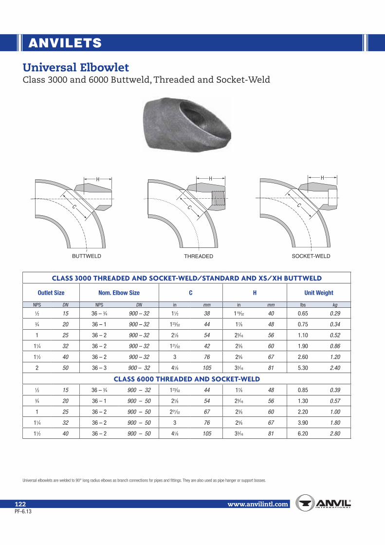
ANVILETS
www.anvilintl.com122
CLASS 3000 THREADED AND SOCKET-WELD/STANDARD AND XS/XH BUTTWELD
Outlet Size Nom. Elbow Size C H Unit Weight
NPS DN NPS DN in mm in mm lbs kg
1⁄2 15 36 – 3⁄4 900 – 32 11⁄2 38 119⁄32 40 0.65 0.29
3⁄4 20 36 – 1 900 – 32 123⁄32 44 17⁄8 48 0.75 0.34
1 25 36 – 2 900 – 32 21⁄8 54 23⁄16 56 1.10 0.52
11⁄4 32 36 – 2 900 – 32 121⁄32 42 23⁄8 60 1.90 0.86
11⁄2 40 36 – 2 900 – 32 3 76 25⁄8 67 2.60 1.20
2 50 36 – 3 900 – 32 41⁄8 105 33⁄16 81 5.30 2.40
CLASS 6000 THREADED AND SOCKET-WELD1⁄2 15 36 – 3⁄4 900 – 32 123⁄32 44 17⁄8 48 0.85 0.39
3⁄4 20 36 – 1 900 – 50 21⁄8 54 23⁄16 56 1.30 0.57
1 25 36 – 2 900 – 50 221⁄32 67 23⁄8 60 2.20 1.00
11⁄4 32 36 – 2 900 – 50 3 76 25⁄8 67 3.90 1.80
11⁄2 40 36 – 2 900 – 50 41⁄8 105 33⁄16 81 6.20 2.80
Universal ElbowletClass 3000 and 6000 Buttweld, Threaded and Socket-Weld
BUTTWELD
H
C
THREADED
H
C
SOCKET-WELD
H
C
PF-6.13

ANVILETS
Mal
leab
le Ir
onCa
st Ir
onSm
all S
teel
Fi
tting
sPi
pe N
ippl
es &
Pipe
Cou
plin
gsFo
rged
Ste
elFi
tting
s &
Unio
nsAn
vile
tsCa
taw
issa
J.B.
Sm
ith P
rodu
cts
www.anvilintl.com 123
CLASS 3000 STANDARD/XS BUTTWELD
Outlet Size Nominal Run Pipe Size H B C Unit Weight
NPS DN NPS DN in mm in mm in mm lbs kg1⁄2 15 21⁄2 – 11⁄4 / 12 – 3 65 – 32 / 300 – 80 13⁄8 35 25⁄32 55 17⁄16 37 0.65 0.29
3⁄4 20 11⁄2 – 11⁄4 / 5 – 2 / 12 – 6 40 – 32 / 125 – 50 / 300 – 150 111⁄16 43 217⁄32 64 13⁄4 44 0.75 0.34
1 25 21⁄2 – 2 / 5 – 3 / 12 – 6 65 – 50 / 125 – 80 / 300 – 150 131⁄32 50 3 76 21⁄8 54 1.10 0.52
11⁄4 32 21⁄2 – 2 / 5 – 3 / 12 – 6 65 – 50 / 125 – 80 / 300 – 150 29⁄32 58 319⁄32 91 25⁄8 67 1.90 0.86
11⁄2 40 21⁄2 – 2 / 5 – 3 / 12 – 6 65 – 50 / 125 – 80 / 300 – 150 215⁄32 63 331⁄32 101 31⁄32 77 2.60 1.20
2 50 5 – 4 / 8 – 6 / 12 – 10 125 – 100 / 200 – 150 / 300 – 150 33⁄16 81 51⁄4 133 41⁄8 105 5.30 2.40
Lateral AnviletsClass 3000 Buttweld and Threaded
BUTTWELD THREADED
H
BC
45
CLASS 3000 THREADED/STANDARD
Outlet Size Nominal Run Pipe Size H B C Unit Weight
NPS DN NPS DN in mm in mm in mm lbs kg1⁄2 15 21⁄2 – 11⁄4 / 12 – 3 65 – 32 / 300 – 80 19⁄16 40 211⁄32 60 17⁄16 37 0.65 0.29
3⁄4 20 11⁄2 – 11⁄4 / 5 – 2 / 12 – 6 40 – 32 / 125 – 50 / 300 – 150 17⁄8 48 23⁄4 70 13⁄4 44 0.75 0.34
1 25 21⁄2 – 2 / 5 – 3 / 12 – 6 65 – 50 / 125 – 80 / 300 – 150 23⁄16 56 31⁄4 83 21⁄8 54 1.10 0.52
11⁄4 32 21⁄2 – 2 / 5 – 3 / 12 – 6 65 – 50 / 125 – 80 / 300 – 150 21⁄2 64 327⁄32 98 25⁄8 67 1.90 0.86
11⁄2 40 21⁄2 – 2 / 5 – 3 / 12 – 6 65 – 50 / 125 – 80 / 300 – 150 23⁄4 70 47⁄32 107 31⁄32 77 2.60 1.20
2 50 5 – 4 / 8 – 6 / 12 – 10 125 – 100 / 200 – 150 / 300 – 150 33⁄8 86 57⁄16 138 41⁄8 105 5.30 2.40
PF-6.13

ANVILETS
www.anvilintl.com124
SOCKET-WELDClass 3000 Flat Anvilet
Outlet SizeDimensions
Unit WeightA B E
NPS DN in mm in mm in mm lbs kg1⁄4 8 3⁄4 19 1 25 9⁄32 7 0.10 0.053⁄8 10 13⁄16 21 11⁄4 32 7⁄16 11 0.20 0.091⁄2 15 1 25 113⁄32 36 9⁄16 14 0.30 0.143⁄4 20 11⁄16 27 123⁄32 44 9⁄16 14 0.35 0.161 25 15⁄16 33 2 51 25⁄32 20 0.60 0.27
11⁄4 32 15⁄16 33 29⁄16 65 3⁄4 19 0.85 0.3911⁄2 40 13⁄8 35 227⁄32 72 3⁄4 19 1.00 0.452 50 11⁄2 38 315⁄32 88 13⁄16 21 1.60 0.73
21⁄2 65 19⁄16 40 41⁄16 103 3⁄4 19 2.75 1.253 80 13⁄4 44 413⁄16 122 15⁄16 24 3.80 1.72
BUTTWELDClass 3000 Flat Anvilet
Outlet SizeDimensions
Unit WeightA B
NPS DN in mm in mm lbs kg1⁄4 8 5⁄8 16 1 25 0.10 0.053⁄8 10 3⁄4 19 11⁄4 32 0.15 0.071⁄2 15 3⁄4 19 13⁄8 35 0.20 0.093⁄4 20 7⁄8 22 13⁄4 44 0.30 0.141 25 11⁄16 27 21⁄8 54 0.50 0.23
11⁄4 32 11⁄4 32 29⁄16 65 0.90 0.4111⁄2 40 15⁄16 33 27⁄8 73 1.10 0.502 50 11⁄2 38 31⁄2 89 1.75 0.79
21⁄2 65 15⁄8 41 41⁄16 103 2.60 1.183 80 13⁄4 44 413⁄16 122 4.10 1.86
THREADEDClass 3000 Flat Anvilet
Outlet SizeDimensions
Unit WeightA B
NPS DN in mm in mm lbs kg1⁄4 8 3⁄4 19 1 25 0.10 0.053⁄8 10 13⁄16 21 11⁄4 32 0.20 0.091⁄2 15 1 25 113⁄32 36 0.25 0.113⁄4 20 11⁄16 27 123⁄32 44 0.35 0.161 25 15⁄16 33 2 51 0.60 0.27
11⁄4 32 15⁄16 33 29⁄16 65 0.90 0.4111⁄2 40 13⁄8 35 227⁄32 72 1.00 0.452 50 11⁄2 38 315⁄32 88 1.75 0.79
21⁄2 65 113⁄16 46 41⁄16 103 3.00 1.363 80 2 51 413⁄16 122 4.35 1.97
Flat AnviletsClass 3000 Threaded, Buttweld and Socket-Weld
BUTTWELD
A
B
A
SOCKET-WELD
B
E
THREADED
A
B
PF-6.13

CATAWISSA
Mal
leab
le Ir
onCa
st Ir
onSm
all S
teel
Fi
tting
sPi
pe N
ippl
es &
Pipe
Cou
plin
gsFo
rged
Ste
elFi
tting
s &
Unio
nsAn
vile
tsCa
taw
issa
J.B.
Sm
ith P
rodu
cts
www.anvilintl.com 125
MaterialASTM A29, A105, A395, A536
Full Traceability:All Catawissa Oilfield Wing Unions are fully traceable and are available with complete mill certifications upon request.
Interchangeability:All Catawissa Oilfield Unions are machined to rigid quality standards ensuring that like components of the same size, fig-ure number and pressure rating are fully interchangeable in the field. Catawissa Oilfield Unions are interchangeable with most leading union manufacturers.
Standard Service:Catawissa Unions are available for Standard Service. Catawissa Oilfield Unions meet or exceed National Association of Corro-sion Engineers standard NACE MR-01-75 and API RP-14E, and are made in an ISO 9001-2008 certified facility. (Sour gas unions are available upon request only.)
Full Range of End Connections:Catawissa Oilfield Wing Unions are also available in threaded ends as well as buttweld and non-pressure seal ends. When you choose Catawissa you receive the utmost in quality, the widest selection and unmatched on-time deliveries.
PF-6.13

CATAWISSA
Warnings:
www.anvilintl.com126
FIGURE 100Threaded Ends
Black Nut/Yellow Subs
Size Item Unit Weight A B C+ TPI Material
NPS DN lbs kg in mm in mm in mm Nuts Subs
2 50
Union Complete 6.25 2.83
3.940 100.08 2.840 72.14 6.250 158.75 3 MOD DI DI
Nut 3.30 1.50Male Sub 1.30 0.59
Female Sub 1.65 0.75
21⁄2 65
Union Complete 10.05 4.56
4.490 114.05 3.390 86.11 7.925 201.30 3 MOD DI DI
Nut 5.30 2.40Male Sub 2.25 1.02
Female Sub 2.50 1.13
3 80
Union Complete 13.65 6.19
5.000 127.00 4.030 102.36 9.000 228.60 3 MOD DI DI
Nut 7.15 3.24Male Sub 3.25 1.47
Female Sub 3.25 1.47
4 100
Union Complete 22.00 9.98
5.940 150.88 5.230 132.84 10.560 268.22 3 MOD DI DI
Nut 9.80 4.44Male Sub 6.65 3.02
Female Sub 5.55 2.52
6 150
Union Complete 45.85 20.79
6.800 172.72 7.390 187.71 13.810 350.77 3STD DI DI
Nut 21.75 9.86Male Sub 11.10 5.03
Female Sub 13.00 5.90
8 200
Union Complete 66.65 30.23
7.230 183.64 9.700 246.38 16.125 409.58 3STD DI DI
Nut 27.40 12.43Male Sub 18.10 8.21
Female Sub 21.15 9.59
FIGURE 100CThreaded Ends
Black Nut/Yellow Subs
Size Item Unit Weight A B C+ TPI Material
NPS DN lbs kg in mm in mm in mm Nuts Subs
2 50 Lug Union 6.25 3.06 3.940 100.08 2.840 72.14 6.250 158.75 3 MOD SF SF
Wing Unions1,000 psi cwp – 1,500 psi test
PF-6.13

CATAWISSA
Mal
leab
le Ir
onCa
st Ir
onSm
all S
teel
Fi
tting
sPi
pe N
ippl
es &
Pipe
Cou
plin
gsFo
rged
Ste
elFi
tting
s &
Unio
nsAn
vile
tsCa
taw
issa
J.B.
Sm
ith P
rodu
cts
Warnings:
www.anvilintl.com 127
FIGURE 200Threaded Ends
Blue Nut/Gray Subs
Size Item Unit Weight A B C+ D TPI Material
NPS Dn lbs kg in mm in mm in mm Nuts Subs
1 25
Union Complete 1.75 0.79
2.67 67.82 1.64 41.66 4.07 103.25 6STD DI SF
Nut 0.95 0.43Male Sub 0.40 0.18
Female Sub 0.40 0.18
11⁄4 32
Union Complete 2.25 1.02
2.73 69.34 1.94 49.15 4.64 117.73 6STD DI SF
Nut 1.20 0.54Male Sub 0.50 0.23
Female Sub 0.55 0.25
11⁄2 40
Union Complete 2.75 1.25
2.77 70.36 2.25 57.15 4.75 120.65 6STD DI SF
Nut 1.30 0.59Male Sub 0.70 0.32
Female Sub 0.75 0.34
† 2 50
Union Complete 4.75 2.15
3.28 83.19 2.83 71.76 5.90 149.86 4STD DI DI
Nut 2.20 1.00
(Ductile Iron)
Male Sub 1.15 0.52Female Sub 1.40 0.63
2 50
Union Complete 5.60 2.54
3.28 83.19 2.83 71.76 5.90 149.86 4STD DI SF
Nut 2.20 1.00
(Forged Steel)
Male Sub 1.20 0.54Female Sub 1.60 0.73
21⁄2 65
Union Complete 10.70 4.85
4.25 107.95 3.40 86.36 7.90 200.66 4STD DI SF
Nut 6.40 2.90Male Sub 2.00 0.91
Female Sub 2.30 1.04
3 80
Union Complete 12.85 5.83
4.66 118.36 4.17 105.92 8.10 205.74 4STD DI SF
Nut 6.00 2.72Male Sub 3.35 1.52
Female Sub 3.50 1.59
4 100
Union Complete 18.70 8.48
4.91 124.71 5.08 128.91 9.06 230.12 3MOD DI SF
Nut 7.40 3.36Male Sub 5.30 2.40
Female Sub 6.00 2.72
6 150
Union Complete 46.10 20.91
6.61 167.89 7.41 188.21 12.80 325.12 3STD DI SF
Nut 18.18 8.24Male Sub 12.74 5.78
Female Sub 15.18 6.88
Wing Unions2,000 psi cwp – 3,000 psi test
PF-6.13

CATAWISSA
Warnings:
www.anvilintl.com128
FIGURE 200Buttweld Ends
Schedule 40Blue Nut/Gray Subs
Size Item Unit Weight A B C+ D TPI Material
NPS Dn lbs kg in mm in mm in mm Nuts Subs
† 2 50
Union Complete 5.50 2.49
3.275 83.19 2.825 71.76 5.900 149.86 4STD DI DI
Nut 2.20 1.00Male Sub 1.50 0.68
Female Sub 1.80 0.82
3 80
Union Complete 14.50 6.58
4.660 118.36 4.170 105.92 8.100 205.74 4STD DI SF
Nut 6.00 2.72Male Sub 3.50 1.59
Female Sub 4.50 2.04
4 100
Union Complete 20.90 9.48
4.910 124.71 5.075 128.91 9.060 230.12 3MOD DI SF
Nut 7.40 3.36Male Sub 6.18 2.80
Female Sub 7.38 3.35
Wing Unions2,000 psi cwp – 3,000 psi test
FIGURE 200CThreaded Ends
Blue Nut/Gray Subs
Size Item Unit Weight A B C+ D TPI Material
NPS Dn lbs kg in mm in mm in mm Nuts Subs
1 25 Lug Union 1.75 0.79 2.670 67.82 1.640 41.66 4.065 103.25 * 6STD SF SF
2 50 Lug Union 4.90 2.22 3.275 83.19 2.825 71.76 5.900 149.86 * 4STD SF SF
PF-6.13

CATAWISSA
Mal
leab
le Ir
onCa
st Ir
onSm
all S
teel
Fi
tting
sPi
pe N
ippl
es &
Pipe
Cou
plin
gsFo
rged
Ste
elFi
tting
s &
Unio
nsAn
vile
tsCa
taw
issa
J.B.
Sm
ith P
rodu
cts
Warnings:
www.anvilintl.com 129
FIGURE 206Threaded Ends
Blue Nut/Gray Subs with Seal Ring
Size Item Unit Weight A B C+ D TPI Material
NPS Dn lbs kg in mm in mm in mm Nuts Subs
1 25
Union Complete 1.75 0.79
2.670 67.82 1.640 41.66 4.065 103.25 6STD DI SF
Nut 0.95 0.43Male w/O-Ring 0.40 0.18
Female Sub 0.40 0.18O-Ring – –
11⁄4 32
Union Complete 2.25 1.02
2.730 69.34 1.935 49.15 4.635 117.73 6STD DI SF
Nut 1.20 0.54Male w/O-Ring 0.50 0.23
Female Sub 0.55 0.25O-Ring – –
11⁄2 40
Union Complete 2.75 1.25
2.770 70.36 2.250 57.15 4.750 120.65 6STD DI SF
Nut 1.30 0.59Male w/O-Ring 0.70 0.32
Female Sub 0.75 0.34O-Ring – –
† 2 50
Union Complete 4.75 2.15
3.275 83.19 2.825 71.76 5.900 149.86 4STD DI Di
Nut 2.20 1.00Male w/O-Ring 1.15 0.52
Female Sub 1.40 0.63O-Ring – –
21⁄2 65
Union Complete 10.70 4.85
4.250 107.95 3.400 86.36 7.900 200.66 4STD DI SF
Nut 6.40 2.90Male w/O-Ring 2.00 0.91
Female Sub 2.30 1.04O-Ring – –
3 80
Union Complete 13.00 5.90
4.660 118.36 4.170 105.92 8.100 205.74 4STD DI SF
Nut 6.00 2.72Male w/O-Ring 3.35 1.52
Female Sub 3.50 1.59O-Ring – –
4 100
Union Complete 18.70 8.48
4.910 124.71 5.075 128.91 9.060 230.12 3MOD DI SF
Nut 7.40 3.36Male w/O-Ring 5.30 2.40
Female Sub 6.00 2.72O-Ring – –
6 150
Union Complete 46.10 20.91
6.610 167.89 7.410 188.21 12.800 325.12 3STD DI SF
Nut 18.18 8.24Male w/O-Ring 12.74 5.78
Female Sub 15.18 6.88O-Ring – –
Wing Unions2,000 psi cwp – 3,000 psi test
PF-6.13

CATAWISSA
Warnings:
www.anvilintl.com130
FIGURE 206Buttweld Ends
Schedule 40Blue Nut/Gray Subs
with Seal Ring
Size Item Unit Weight A B C+ D TPI Material
NPS Dn lbs kg in mm in mm in mm Nuts Subs
† 2 50
Union Complete 6.00 2.72
3.275 83.19 2.825 71.76 5.900 149.86 4STD DI DI
Nut 2.20 1.00Male w/O-Ring 1.50 0.68
Female Sub 1.50 0.68O-Ring – –
3 80
Union Complete 14.50 6.58
4.660 118.36 4.170 105.92 8.100 205.74 4STD DI SF
Nut 6.00 2.73Male w/O-Ring 3.50 1.59
Female Sub 4.50 2.04O-Ring – –
4 100
Union Complete 20.90 9.48
4.910 124.71 5.075 128.91 9.060 230.12 3MOD DI SF
Nut 7.40 3.36Male w/O-Ring 6.18 2.80
Female Sub 7.38 3.35O-Ring – –
6 150
Union Complete 45.00 20.41
6.610 167.89 7.410 188.21 12.800 325.12 3STD DI SF
Nut 18.18 8.26Male w/O-Ring 13.00 5.90
Female Sub 14.00 6.35O-Ring – –
FIGURE 202Blanking Cap Only
with O-Ring
Size Unit Weight Description
NPS Dn lbs kg
4 100 9.00 4.10
Wing Unions2,000 psi cwp – 3,000 psi test
PF-6.13

CATAWISSA
Mal
leab
le Ir
onCa
st Ir
onSm
all S
teel
Fi
tting
sPi
pe N
ippl
es &
Pipe
Cou
plin
gsFo
rged
Ste
elFi
tting
s &
Unio
nsAn
vile
tsCa
taw
issa
J.B.
Sm
ith P
rodu
cts
www.anvilintl.com 131
FIGURE 211Insulating Union Threaded Ends
Gray Nut/Light Blue Subs
Size Item Unit Weight A B C TPI Material
NPS Dn lbs kg in mm in mm in mm Nuts Subs
1 25
Union Complete 2.34 1.06
2.830 71.88 1.560 39.62 4.660 118.36 6STD SF SF
Nut 1.42 0.64Male Sub 0.40 0.18
Female Sub 0.52 0.24Seal Ring Kit – –
2 50
Union Complete 6.24 2.83
3.510 89.15 2.880 73.15 6.250 158.75 6STD SF SF
Nut 2.96 1.34Male Sub 1.42 0.64
Female Sub 1.86 0.84Seal Ring Kit – –
Wing Unions2,000 psi cwp – 3,000 psi test
FIGURE 300Flat-Face Union
Gray Nut/Yellow Subs
Size Item Unit Weight A B C Material
NPS Dn lbs kg in mm in mm in mm Nuts Subs
Straight Away Breakout
1 25
Union Complete 2.21 1.00
2.625 66.68 1.560 39.62 4.250 107.95 DI SFNut 1.50 0.68
Male Sub 0.31 0.14Female Sub w/O-Ring 0.50 0.23
Seal Ring – –
2 50
Union Complete 6.00 2.72
3.750 95.25 2.780 70.61 5.750 146.05 DI SFNut 3.31 1.50
Male Sub 1.25 0.57Female Sub w/O-Ring 1.44 0.65
Seal Ring – –
21⁄2 65
Union Complete 10.88 4.93
4.625 117.48 3.410 86.61 7.000 177.8 DI SFNut 6.19 2.81
Male Sub 2.13 0.97Female Sub w/O-Ring 2.56 1.16
Seal Ring – –
3 80
Union Complete 14.25 6.46
5.000 127.00 4.300 109.22 8.000 203.2 DI SFNut 6.31 2.86
Male Sub 3.50 1.59Female Sub w/O-Ring 4.44 2.01
Seal Ring – –
4 100
Union Complete 20.69 9.38
5.750 146.05 5.110 129.79 8.875 225.43 DI SFNut 8.31 3.77
Male Sub 5.57 2.53Female Sub w/O-Ring 6.63 3.01
Seal Ring – –
PF-6.13

CATAWISSA
Warnings:
www.anvilintl.com132
FIGURE 400Threaded Ends
Black Nut/Red Subs
Size Item Unit Weight A B C TPI Material
NPS Dn lbs kg in mm in mm in mm Nuts Subs
2 50
Union Complete 11.05 5.01
5.225 132.72 3.000 76.20 7.125 180.98 3STD SF SF
Nut 5.60 2.54Male Sub 2.65 1.20
Female Sub 2.80 1.27
3 80
Union Complete 20.00 9.07
6.110 155.19 4.250 107.95 8.750 222.25 3STD SF SF
Nut 8.50 3.85Male Sub 5.50 2.49
Female Sub 6.00 2.72
4 100
Union Complete 29.15 13.22
8.200 208.28 5.275 133.99 9.160 232.66 3STD SF SF
Nut 10.15 4.60Male Sub 8.85 4.01
Female Sub 10.15 4.60
Wing Unions3,000 psi cwp – 4,500 psi test
4,000 psi cwp – 6,000 psi test
FIGURE 301Steam Service Union
Black Nut/Green Subs
Size Item Unit Weight A B C TPI Material
NPS Dn lbs kg in mm in mm in mm Nuts Subs
1 25
Union Complete 1.75 0.79
2.670 67.82 1.640 41.66 4.065 103.38 6STD SF SF
Nut – –Male Sub – –
Female Sub – –Seal Ring – –
2 50
Union Complete 4.90 2.22
3.275 83.31 2.825 71.88 5.900 149.86 31⁄2STD SF SF
Nut – –Male Sub – –
Female Sub – –Seal Ring – –
3 80
Union Complete 13.25 6.01
4.660 118.36 4.170 105.92 8.100 205.74 4STD SF SF
Nut – –Male Sub – –
Female Sub – –Seal Ring – –
PF-6.13

CATAWISSA
Mal
leab
le Ir
onCa
st Ir
onSm
all S
teel
Fi
tting
sPi
pe N
ippl
es &
Pipe
Cou
plin
gsFo
rged
Ste
elFi
tting
s &
Unio
nsAn
vile
tsCa
taw
issa
J.B.
Sm
ith P
rodu
cts
Warnings:
www.anvilintl.com 133
FIGURE 600Threaded Ends
Black Nut/Silver Subs
Size Item Unit Weight A B C TPI Material
NPS Dn lbs kg in mm in mm in mm Nuts Subs
1 25
Union Complete 3.65 1.66
3.565 90.55 1.750 44.45 4.500 114.3 6STD SF BS
Nut 1.95 0.88Male Sub 0.65 0.29
Female Sub w/Bronze Seat 1.05 0.48Bronze Seat Insert 0.05 0.023
11⁄2 40
Union Complete – –
* * * * * * 4STD SF BS
Nut – –Male Sub – –
Female Sub w/Bronze Seat – –Bronze Seat Insert – –
2 50
Union Complete 15.64 7.09
6.440 163.58 3.010 76.45 7.160 181.86 2STD SF
(F) ST
(M) SF
Nut 7.08 3.21Male Sub 3.22 1.46
Female Sub w/Bronze Seat 5.34 2.42Bronze Seat Insert 0.65 0.30
3 80
Union Complete 27.25 12.36
8.875 225.43 4.1875 106.36 8.750 222.25 2STD SF SF
Nut – –Male Sub – –
Female Sub w/Bronze Seat – –Bronze Seat Insert – –
4 100
Union Complete 40.00 18.14
10.0625 255.59 5.250 133.35 10.625 269.88 2STD SF SF
Nut 14.25 6.48Male Sub 11.00 5.00
Female Sub w/Bronze Seat 12.65 5.75Bronze Seat Insert 2.15 0.98
Wing Unions4,000 psi cwp – 6,000 psi test
6,000 psi cwp – 9,000 psi test
FIGURE 400Buttweld Ends
Schedule 80 Black Nut/Red Subs
Size Item Unit Weight A B C TPI Material
NPS Dn lbs kg in mm in mm in mm Nuts Subs
2 50
Union Complete 10.75 4.88
5.225 132.72 3.00 76.20 7.125 180.98 3STD SF SF
Nut 5.60 2.54Male Sub 2.75 1.25
Female Sub 3.00 1.36
PF-6.13

CATAWISSA
Warnings:
www.anvilintl.com134
FIGURE 602Threaded Ends
Black Nut/Orange Subs
Size Item Unit Weight A B C TPI Material
NPS Dn lbs kg in mm in mm in mm Nuts Subs
1 25
Union Complete 3.55 1.61
6.625 168.28 1.750 44.45 4.500 114.30 6STD SF SF
Nut 1.95 0.88Male Sub 0.60 0.27
Female Sub w/Ring 1.00 0.45Seat Ring – –
11⁄2 40
Union Complete 9.54 4.33
4.600 116.84 2.570 65.28 5.520 140.21 4STD SF SF
Nut 4.98 2.26Male Sub 1.98 0.90
Female Sub w/Ring 2.58 1.17Seat Ring – –
2 50
Union Complete 12.40 5.62
5.300 134.62 2.970 75.44 6.875 174.63 3MOD SF SF
Nut 6.50 2.95Male Sub 2.85 1.29
Female Sub w/Ring 3.05 1.38Seat Ring – –
3 80
Union Complete 22.30 10.11
6.310 160.27 4.250 107.95 8.875 225.43 3MOD SF SF
Nut 9.95 4.51Male Sub 5.20 2.36
Female Sub w/Ring 7.15 3.24Seat Ring – –
4 100
Union Complete 32.18 14.59
8.300 210.82 5.200 132.08 10.040 255.02 3MOD SF SF
Nut 13.30 6.03Male Sub 8.36 3.79
Female Sub w/Ring 10.52 4.77Seat Ring – –
Wing Unions6,000 psi cwp – 9,000 psi test
PF-6.13

CATAWISSA
Mal
leab
le Ir
onCa
st Ir
onSm
all S
teel
Fi
tting
sPi
pe N
ippl
es &
Pipe
Cou
plin
gsFo
rged
Ste
elFi
tting
s &
Unio
nsAn
vile
tsCa
taw
issa
J.B.
Sm
ith P
rodu
cts
Warnings:
www.anvilintl.com 135
FIGURE 602Buttweld Ends
Schedule 80Black Nut/Orange Subs
Size Item Unit Weight A B C TPI Material
NPS Dn lbs kg in mm in mm in mm Nuts Subs
2 50
Union Complete 12.12 5.50
5.300 134.62 2.970 75.44 6.875 174.63 3MOD SF SF
Nut 6.50 2.95Male Sub 2.76 1.25
Female Sub w/Ring 2.82 1.28Seat Ring – –
3 80
Union Complete 21.25 9.64
6.310 160.27 4.250 107.95 8.875 225.43 3MOD SF SF
Nut 9.95 4.51Male Sub 5.75 2.61
Female Sub w/Ring 6.00 2.72Seat Ring – –
4 100
Union Complete 28.25 12.81
8.300 210.82 5.200 132.08 10.040 255.02 3MOD SF SF
Nut 13.30 6.03Male Sub 7.50 3.40
Female Sub w/Ring 9.75 4.42Seat Ring – –
FIGURE 607Well Service Union
Threaded EndsYellow Nut/Silver Subs
Size Item Unit Weight A B C TPI Material
NPS Dn lbs kg in mm in mm in mm Nuts Subs
11⁄2 40
Union Complete 8.96 4.06
4.15 105.41 2.6 66.04 6.53 165.74 5STD SF SF
Nut 5.34 2.42Male Sub 1.52 0.69
Female Sub w/Ring 2.10 0.95Seat Ring – –
2 50
Union Complete 14.64 6.64
5.85 148.59 3.08 78.23 7.33 186.18 5STD SF SF
Nut 7.68 3.48Male Sub 2.82 1.28
Female Sub w/Ring 4.14 1.88Seat Ring – –
Wing Unions6,000 psi cwp – 9,000 psi test
PF-6.13

CATAWISSA
Warnings:
www.anvilintl.com136
FIGURE 1002Threaded Ends
Red Nut/Blue Subs
Size Item Unit Weight A B C TPI Material
NPS Dn lbs kg in mm in mm in mm Nuts Subs
1 25
Union Complete 3.62 1.64
3.620 91.95 1.750 44.45 4.500 114.30 6STD
All AlloySteel
Forging
Nut 2.02 0.92Male Sub 0.70 0.32
Female Sub w/Ring 0.90 0.41Seat Ring – –
11⁄2 40
Union Complete 9.54 4.33
4.600 116.84 2.570 65.28 5.520 140.21 4STD
Nut 4.98 2.26Male Sub 1.98 0.90
Female Sub w/Ring 2.58 1.17Seat Ring – –
2 50
Union Complete 13.00 5.90
5.200 132.08 3.000 76.20 7.375 187.33 3MOD
Nut 7.35 3.33Male Sub 2.65 1.20
Female Sub w/Ring 3.00 1.36Seat Ring – –
3 80
Union Complete 22.40 10.16
6.200 157.48 4.240 107.70 9.320 236.73 4STD
Nut 10.70 4.85Male Sub 5.28 2.39
Female Sub w/Ring 6.42 2.91Seat Ring – –
4 100
Union Complete 33.82 15.34
8.280 210.31 5.250 133.35 10.700 271.78 4STD
Nut 14.70 6.67Male Sub 8.60 3.90
Female Sub w/Ring 10.52 4.77Seat Ring – –
Wing Unions10,000 psi cwp – 15,000 psi test
PF-6.13

CATAWISSA
Mal
leab
le Ir
onCa
st Ir
onSm
all S
teel
Fi
tting
sPi
pe N
ippl
es &
Pipe
Cou
plin
gsFo
rged
Ste
elFi
tting
s &
Unio
nsAn
vile
tsCa
taw
issa
J.B.
Sm
ith P
rodu
cts
Warnings:
www.anvilintl.com 137
Wing Unions10,000 psi cwp – 15,000 psi test
FIGURE 1002Buttweld EndsSchedule XXH
Red Nut/Blue Subs
Size Item Unit Weight A B C TPI Material
NPS Dn lbs kg in mm in mm in mm Nuts Subs
2 50
Union Complete 13.16 5.97
5.200 132.08 3.000 76.20 7.375 187.33 3MOD
All AlloySteel
Forging
Nut 7.35 3.34Male Sub 3.44 1.56
Female Sub w/Ring 3.18 1.44Seat Ring – –
3 80
Union Complete 25.52 11.57
6.200 157.48 4.240 107.70 9.320 236.73 4STD
Nut 10.70 4.86Male Sub 7.70 3.49
Female Sub w/Ring 7.42 3.37Seat Ring – –
4 100
Union Complete 34.04 15.44
8.280 210.31 5.250 133.35 10.700 271.78 4STD
Nut 14.70 6.68Male Sub 9.36 4.24
Female Sub w/Ring 10.34 4.69Seat Ring – –
FIGURE 1002Buttweld EndsSchedule 160
Red Nut/Blue Subs
Size Item Unit Weight A B C TPI Material
NPS Dn lbs kg in mm in mm in mm Nuts Subs
2 50
Union Complete 14.25 6.46
5.200 132.08 3.000 76.20 7.375 187.33 3MOD
All AlloySteel
Forging
Nut 7.35 3.34Male Sub 3.50 1.59
Female Sub w/Ring 3.75 1.70Seat Ring – –
3 80
Union Complete 21.25 9.64
6.200 157.48 4.240 107.70 9.320 236.73 4STD
Nut 10.70 4.86Male Sub 5.75 2.61
Female Sub w/Ring 6.00 2.72Seat Ring – –
4 100
Union Complete 31.5 14.29
8.280 210.31 5.250 133.35 10.700 271.78 4STD
Nut 14.70 6.68Male Sub 9.00 4.08
Female Sub w/Ring 9.50 4.31Seat Ring – –
PF-6.13

CATAWISSA
Warnings:
www.anvilintl.com138
Wing Unions15,000 psi cwp – 22,500 psi test
FIGURE 1502Threaded Ends
Blue Nut/Red Subs
Size Item Unit Weight A B C D TPI Material
NPS Dn lbs kg in mm in mm in mm Nuts Subs
2 50
Union Complete 19.46 8.83
7.060 179.32 3.230 82.04 7.860 199.64 3STD
All AlloySteel
Forging
Nut 9.78 4.44Male Sub 4.82 2.19
Female Sub w/Ring 4.86 2.20Seat Ring – –
3 80
Union Complete 30.48 13.82
7.630 193.8 4.400 111.76 9.900 251.46 31⁄2STD
Nut 14.18 6.43Male Sub 8.00 3.63
Female Sub w/Ring 8.30 3.76Seat Ring – –
FIGURE 1502Buttweld EndsSchedule XXH
Blue Nut/Red Subs
Size Item Unit Weight A B C D TPI Material
NPS Dn lbs kg in mm in mm in mm Nuts Subs
2 50
Union Complete 20.58 9.33
7.060 179.32 3.230 82.04 7.860 199.64 3STD
All AlloySteel
Forging
Nut 9.78 4.44Male Sub 5.32 2.41
Female Sub w/Ring 5.48 2.49Seat Ring – –
3 80
Union Complete 27.98 12.69
7.630 193.8 4.400 111.76 9.900 251.46 31⁄2STD
Nut 14.18 6.43Male Sub 6.96 3.16
Female Sub w/Ring 7.76 3.52Seat Ring – –
FIGURE 1502Buttweld EndsSchedule 160
Blue Nut/Red Subs
Size Item Unit Weight A B C D TPI Material
NPS Dn lbs kg in mm in mm in mm Nuts Subs
2 50
Union Complete 20.06 9.10
7.060 179.32 3.230 82.04 7.860 199.64 3STD
All AlloySteel
Forging
Nut 9.78 4.44Male Sub 5.06 2.30
Female Sub w/Ring 5.22 2.37Seat Ring – –
3 80
Union Complete 27.81 12.61
7.630 193.8 4.400 111.76 9.900 251.46 31⁄2STD
Nut 14.18 6.43Male Sub 6.51 2.95
Female Sub w/Ring 7.12 3.23Seat Ring – –
PF-6.13

CATAWISSA
Mal
leab
le Ir
onCa
st Ir
onSm
all S
teel
Fi
tting
sPi
pe N
ippl
es &
Pipe
Cou
plin
gsFo
rged
Ste
elFi
tting
s &
Unio
nsAn
vile
tsCa
taw
issa
J.B.
Sm
ith P
rodu
cts
Warnings:
www.anvilintl.com 139
FIGURE S1AHigh Speed Union
3000# Forged Steel
Size Unit Weight
NPS Dn lbs kg
1 25 1.50 0.68
2 50 4.50 2.04
3 80 12.19 5.53
FIGURE 3L S1ATri-Lug High Speed Union
3000# Forged Steel
Size Unit Weight
NPS Dn lbs kg
1 25 2.15 0.98
11⁄2 50 3.64 1.65
2 80 5.85 2.66
High Speed Unions3,000 psi cwp — 4,500 psi test
PF-6.13

CATAWISSA
Warnings:
www.anvilintl.com140
Catawissa Quick Reference Chart
STANDARD SERVICE
Fig No. CWP TESTAPI Color Code Pipe Size (in.)
SUB NUT 1" 1¼" 1½" 2" 2½" 3" 4" 6"
100 1,000 1,500 Yellow Black
200 2,000 3,000 Gray Blue
206 2,000 3,000 Gray Blue
211 2,000 3,000Light Blue
Gray
300 2,000 3,000 Yellow Gray
301 3,000 4,500 Green Black
400 4,000 6,000 Red Black
600 6,000 9,000 Silver Black
602 6,000 9,000 Orange Black
607 6,000 9,000 Silver Yellow
1002 10,000 15,000 Blue Red
1502 15,000 22,500 Red Blue
PF-6.13

J.B. SMITH PRODUCTS
Mal
leab
le Ir
onCa
st Ir
onSm
all S
teel
Fi
tting
sPi
pe N
ippl
es &
Pipe
Cou
plin
gsFo
rged
Ste
elFi
tting
s &
Unio
nsAn
vile
tsCa
taw
issa
J.B.
Sm
ith P
rodu
cts
www.anvilintl.com 141
J.B. Smith oil country tubular fittings, swages and bull plugs add an important dimension to the industry’s leading line of flow control products offered by Anvil. J.B. Smith is a respected name and its products are well known for high quality and consistency.
Full TraceabilityAll J.B. Smith swages, bull plugs, tubing and casing nipples, and chambers are traceable to the original mill test report. To ensure traceability, all fittings are steel stamped as follows:
Material Specification• Material Grade WPB (ASTM A234 - Line Pipe)• Material Grade J-55, K-55, L-80, N-80
(API 5CT - Oil Country Sizes)
Raw Material CodeEach is stamped with unique JBS material code for traceability to material type, details of purchase and mill test report.
Heat TreatmentItems made to specification grades requiring final heat treatment bear an additional two letter code for heat treatment traceability.
All J.B. Smith products conform to the following applicable specifications:• API 5B – Threading Oil Country size
• API 5CT – Raw material, Process, End Finish (Oil Country Sizes)
• ASME B1.20.1 – Threading Line Pipe• ASME B16.9 – Weld Bevels• MSS SP-95 Swage and Bull Plug• ASTM A234 WPB – Raw material, Process, End Finish
(Line Pipe High Temp)
• ASTM A420 WPL6 – Raw material, Process, End Finish (Line Pipe Low Temp)
• ASTM B633 Type III Class III – Zinc Electroplate• NACE MR-01-75 – As Applicable
PF-6.13

J.B. SMITH PRODUCTS
www.anvilintl.com142
Swage Nipples, Bull Plugs, Oil Country Fittings, Couplings, Stainless SwagesManufacturing SpecificationJ.B. Smith manufactures swage nipples and bull plugs in accordance to the applicable specification, API 5CT, ASTM A234, MSS SP-95. Materials include ASTM A106, GR B seamless pipe, A-1000 low to medium carbon, fine grain bar stock, API grades J-55 through N-80 tubing and casing, processed and heat treated to applicable specification requirements. Fitting chemical and physical properties fall within the ranges listed below.
All fittings are manufactured in the U.S.A.
TraceabilityAll material purchased by J.B. Smith is fully traceable to the mill source. A unique JBS material code appears on all products made since the institution of this program. As a result, mill test reports are now available at any time on products so coded (See EXTRAS for MTR charges.)
Pressure RatingsDue to the wide variation in service conditions, temperature, vibrations, etc., J.B. Smith Mfg. can make no recommendations as to allowable working pressure of swage nipples and bull plugs. There are a number of working pressure formulas from which the end user may choose to determine the required wall thickness of the piping system. It is our responsibility only to furnish a fitting with end dimensions equal to those of the pipe size and schedule ordered.
Material Certification – Carbon SteelJ.B Smith certifies that the material used to manufacture line pipe sizes of swage nipples and bull plugs has be processed to comply with the requirements of ASTM A234 grade WPB and the chemical and physical properties of the fittings fall within the ranges listed below.
MarkingAll J.B. Smith fittings are permanently marked as follows:
• Manufacturer’s symbol -• Material Specification or Grade
WBP (Line Pipe Sizes)
J-55, K-55, L-80, N-80 (Oil Country Sizes)
• Raw Material Code - Each part is die stamped with unique JBS material code for traceability to material type, details of purchase and mill test report.
• Heat Treatment - Heat treatments are performed to ASTM A234 WPB or API 5CT specification grade requirement as applicable. Fittings bear a two letter code provide traceability to final heat treatment.
ThreadingLine Pipe, Tubing and Casing threads conform to ASME B1.20.1 B or API 5B as applicable.
Oil Country Industry Thread Color CodeIndustry Color Codes as follows:
8R - Red 10R - Yellow 10V - Blue 111⁄2 V - Green LP - Silver
Coatings• Zinc Electroplate - ASTM B633 Type III Class III
• Paint (Weld Bevel Ends)
Weld BevelsWeld bevels are machined per ASME B16.9 specifications.
Note:• Fittings made from bar or plate may have 0.35 Max Carbon.• Fittings made from forgings may have a 0.35 Max Carbon and 0.35 Max Silicon.• For each reduction of 0.01% below the specified carbon maximum, an increase of 0.06% manganese above the specified maximum will be permitted,
up to a maximum of 1.35%.• The sum of Copper, Nickel Chromium and Molybdenum shall not exceed 1.00%.• The sum of Chromium and Molybdenum shall not exceed 0.32%.
Chemical and Physical RequirementsAPI 5CT MATERIAL
Chemical Requirements
Grp Gr C Mn Mo Cr Ni Cu P S Si1 J55 — — — — — — 0.030 Max 0.030 Max —1 K55 — — — — — — 0.030 Max 0.030 Max —1 N80 Type1 — — — — — — 0.030 Max 0.030 Max —2 L80 Type1 0.43 Max 1.90 Max — — 0.25 Max 0.35 Max 0.030 Max 0.030 Max 0.45 Max
Physical Requirements
Grp Gr Total Elongation under load % Yield Strength ksi Tensile Strength ksi Hardness
1 J55 0.5 55-80 75 — —1 K55 0.5 55-80 95 — —1 N80 Type1 0.5 80-110 100 — —2 L80 Type1 0.5 80-110 95 23 241
PF-6.13

J.B. SMITH PRODUCTS
Mal
leab
le Ir
onCa
st Ir
onSm
all S
teel
Fi
tting
sPi
pe N
ippl
es &
Pipe
Cou
plin
gsFo
rged
Ste
elFi
tting
s &
Unio
nsAn
vile
tsCa
taw
issa
J.B.
Sm
ith P
rodu
cts
www.anvilintl.com 143
Carbon SteelSwage Nipples
Line Pipe Swages• Nominal Pipe Size range 1⁄8 – 8 NPS (6 – 200 DN)• Manufactured from A106 Gr. B seamless pipe or hex bar and
processed in accordance to ASTM A234 Gr. WPB• Choice of material depends upon size and reduction• Available in standard, extra heavy, double extra heavy or
schedule 160
• End finishes available: NPT, weld beveled, squared cut (for socket weld) or grooved
• Available concentric and eccentric• 1" (25mm) and smaller are made from hex bar• 11⁄4" (32mm) and larger are made from pipe
(25 DN)
(25 DN) ⁄ (32 DN)
Concentric Swage Nipples
SizeLength Standard
WeightXS/XH Weight
XXS/XXH & Sch. 160
WeightPipe API or O.D. Reduced to Size
NPS DN in mm NPS DN in mm lbs kg lbs kg lbs kg
1⁄4 8 0.540 14 1⁄8 6 21⁄4 57 – – – – 0.25 0.11
3⁄8 10 0.675 171⁄8 6 21⁄2 64 – – 0.25 0.11 0.38 0.17
1⁄4 8 21⁄2 64 – – 0.25 0.11 0.38 0.17
1⁄2 15 0.840 211⁄8 6 23⁄4 70 – – 0.33 0.15 0.50 0.23
1⁄4 and 3⁄8 8 and 10 23⁄4 70 – – 0.33 0.15 0.50 0.23
3⁄4 20 1.050 27
1⁄8 6 3 76 – – 0.50 0.23 0.75 0.34
1⁄4 and 3⁄8 8 and 10 3 76 – – 0.50 0.23 0.75 0.34
1⁄2 15 3 76 – – 0.50 0.23 0.75 0.34
1 25 1.315 33
1⁄8 6 31⁄2 89 – – 0.66 0.30 1.00 0.45
1⁄4 and 3⁄8 8 and 10 31⁄2 89 – – 0.66 0.30 1.00 0.45
1⁄2 and 3⁄4 15 and 20 31⁄2 89 – – 0.66 0.30 1.00 0.45
PF-6.13

J.B. SMITH PRODUCTS
www.anvilintl.com144
Concentric Swage Nipples
SizeLength Standard
WeightXS/XH Weight
XXS/XXH & Sch. 160
WeightPipe API or O.D. Reduced to Size
NPS DN in mm NPS DN in mm lbs kg lbs kg lbs kg
11⁄4 32 1.660 42
1⁄4 and 3⁄8 8 and 10 4 102 – – 1.00 0.45 1.5 0.681⁄2 and 3⁄4 15 and 20 4 102 – – 1.00 0.45 1.5 0.68
1 25 4 102 – – 1.00 0.45 1.5 0.68
11⁄2 40 1.900 48
1⁄4 and 3⁄8 8 and 10 41⁄2 114 – – 1.2 0.53 2.0 0.911⁄2 and 3⁄4 15 and 20 41⁄2 114 – – 1.2 0.53 2.0 0.91
1 25 41⁄2 114 – – 1.2 0.53 2.0 0.9111⁄4 32 41⁄2 114 – – 1.2 0.53 2.0 0.91
2 50 23⁄8 60
1⁄4 and 3⁄8 8 and 10 61⁄2 165 – – 3.0 1.4 4.3 1.91⁄2 and 3⁄4 15 and 20 61⁄2 165 – – 3.0 1.4 4.3 1.9
1 25 61⁄2 165 2.0 0.91 2.3 1.1 4.3 1.911⁄4 32 61⁄2 165 2.0 0.91 2.3 1.1 4.3 1.911⁄2 40 61⁄2 165 2.0 0.91 2.3 1.1 4.3 1.9
21⁄2 65 27⁄8 73
1⁄2 and 3⁄4 15 and 20 7 178 – – 3.5 1.6 8.0 3.61 25 7 178 3.0 1.4 3.5 1.6 8.0 3.6
11⁄4 32 7 178 3.0 1.4 3.5 1.6 8.0 3.611⁄2 40 7 178 3.0 1.4 3.5 1.6 8.0 3.62 50 7 178 3.0 1.4 3.5 1.6 8.0 3.6
3 80 31⁄2 89
1⁄2 and 3⁄4 15 and 20 8 203 – – 6.0 2.7 11 5.01 25 8 203 4.5 2.0 6.0 2.7 11 5.0
11⁄4 32 8 203 4.5 2.0 6.0 2.7 11 5.011⁄2 40 8 203 4.5 2.0 6.0 2.7 11 5.0
2 and 21⁄2 50 and 65 8 203 4.5 2.0 6.0 2.7 11 5.031⁄2 90 4 100 1⁄2 thru 11⁄2 15 thru 40 8 203 5.5 2.5 7.5 3.4 14 6.1
31⁄2 90 4 1001⁄2 thru 11⁄2 15 thru 40 8 203 5.5 2.5 7.5 3.4 14 6.12 thru 3 50 thru 80 8 203 5.5 2.5 7.5 3.4 14 6.1
4 100 41⁄2 114
1⁄2 and 3⁄4 15 and 20 9 229 – – 10.0 4.5 18 8.21 25 9 229 7.5 3.4 10.0 4.5 18 8.2
11⁄4 and 11⁄2 32 and 40 9 229 7.5 3.4 10.0 4.5 18 8.22 50 9 229 7.5 3.4 10.0 4.5 18 8.2
21⁄2 65 9 229 7.5 3.4 10.0 4.5 18 8.23 and 31⁄2 80 and 90 9 229 7.5 3.4 10.0 4.5 18 8.2
5 125 59⁄16 140
1 thru 11⁄2 25 thru 40 11 279 12 5.2 17 7.7 33 152 and 21⁄2 50 and 65 11 279 12 5.2 17 7.7 33 153 and 31⁄2 80 and 90 11 279 12 5.2 17 7.7 33 15
4 100 11 279 12 5.2 17 7.7 33 15
6 150 65⁄8 168
1 thru 11⁄2 25 thru 40 12 305 17 7.7 25 11 46 212 and 21⁄2 50 and 65 12 305 17 7.7 25 11 46 213 and 31⁄2 80 and 90 12 305 17 7.7 25 11 46 21
4 100 12 305 17 7.7 25 11 46 215 125 12 305 17 7.7 25 11 46 21
8 200 85⁄8 2192 thru 3 50 thru 80 13 330 29 13 44 20 78 354 and 5 100 and 125 13 330 29 13 44 20 78 35
6 150 13 330 29 13 44 20 78 35
Carbon SteelSwage Nipples
PF-6.13

J.B. SMITH PRODUCTS
Mal
leab
le Ir
onCa
st Ir
onSm
all S
teel
Fi
tting
sPi
pe N
ippl
es &
Pipe
Cou
plin
gsFo
rged
Ste
elFi
tting
s &
Unio
nsAn
vile
tsCa
taw
issa
J.B.
Sm
ith P
rodu
cts
www.anvilintl.com 145
EccentricSwage Nipples
SizeLength Standard
WeightXS/XHWeight
XXS/XXH & Sch. 160
WeightPipe API or O.D. Reduced to Size
NPS DN in mm NPS DN in mm lbs kg lbs kg lbs kg1⁄4 8 0.540 14 1⁄8 6 21⁄4 57 – – 0.16 0.07 0.25 0.11
3⁄8 10 0.675 171⁄8 6 21⁄2 64 – – 0.25 0.11 0.38 0.171⁄4 8 21⁄2 64 – – 0.25 0.11 0.38 0.17
1⁄2 15 0.840 21 1⁄4 and 3⁄8 8 and 10 23⁄4 70 – – 0.33 0.15 0.50 0.23
3⁄4 20 1.050 271⁄4 and 3⁄8 8 and 10 3 76 – – 0.50 0.23 0.75 0.34
1⁄2 15 3 76 – – 0.50 0.23 0.75 0.34
1 25 1.315 331⁄4 and 3⁄8 8 and 10 31⁄2 89 – – 0.66 0.30 1.00 0.451⁄2 and 3⁄4 15 and 20 31⁄2 89 – – 0.60 0.27 1.00 0.45
11⁄4 32 1.660 421⁄2 and 3⁄4 15 and 20 4 102 – – 1.00 0.45 1.5 0.68
1 25 4 102 – – 1.00 0.45 1.5 0.68
11⁄2 40 1.900 48
1⁄2 and 3⁄4 15 and 20 41⁄2 114 – – 1.2 0.53 2.0 0.911 25 41⁄2 114 – – 1.2 0.53 2.0 0.91
11⁄4 32 41⁄2 114 – – 1.2 0.53 2.0 0.91
2 50 23⁄8 60
1⁄4 and 3⁄8 8 and 10 61⁄2 165 – – 3.0 1.4 4.3 1.91⁄2 and 3⁄4 15 and 20 61⁄2 165 – – 3.0 1.4 4.3 1.9
1 25 61⁄2 165 2.0 0.91 2.3 1.1 4.3 1.911⁄4 32 61⁄2 165 2.0 0.91 2.3 1.1 4.3 1.911⁄2 40 61⁄2 165 2.0 0.91 2.3 1.1 4.3 1.9
21⁄2 65 27⁄8 73
1 25 7 178 – – 3.5 1.6 8.0 3.611⁄4 32 7 178 3.0 1.4 3.5 1.6 8.0 3.611⁄2 40 7 178 3.0 1.4 3.5 1.6 8.0 3.62 50 7 178 – – 3.5 1.6 8.0 3.6
3 80 31⁄2 89
1⁄2 and 3⁄4 15 and 20 8 203 – – 6.0 2.7 11 5.01 25 8 203 4.5 2.0 6.0 2.7 11 5.0
11⁄4 32 8 203 4.5 2.0 6.0 2.7 11 5.011⁄2 40 8 203 4.5 2.0 6.0 2.7 11 5.0
2 and 21⁄2 50 and 65 8 203 4.5 2.0 6.0 2.7 11 5.0
31⁄2 90 4 102 All reductions
All reductions 8 203 5.5 2.5 7.5 3.4 14 6.1
4 100 41⁄2 114
1 25 9 229 7.5 3.4 10.0 4.5 18 8.211⁄4 and 11⁄2 32 and 40 9 229 7.5 3.4 10.0 4.5 18 8.2
2 50 9 229 7.5 3.4 10.0 4.5 18 8.221⁄2 65 9 229 7.5 3.4 10.0 4.5 18 8.2
3 and 31⁄2 80 and 90 9 229 7.5 3.4 10.0 4.5 18 8.2
Carbon SteelSwage Nipples
PF-6.13

J.B. SMITH PRODUCTS
www.anvilintl.com146
Stainless & Alloy SteelSwage Nipples
304 Stainless Steel 316 Stainless Steel
Size Length Size LengthNPS DN in mm NPS DN in mm
1⁄4 x 1⁄8 8 x 6 21⁄4 57 1⁄4 x 1⁄8 8 x 6 21⁄4 573⁄8 x 1⁄4 10 x 8 21⁄2 64 3⁄8 x 1⁄4 10 x 8 21⁄2 641⁄2 x 1⁄4 15 x 8 23⁄4 70 1⁄2 x 1⁄4 15 x 8 23⁄4 701⁄2 x 3⁄8 15 x 10 23⁄4 70 1⁄2 x 3⁄8 15 x 10 23⁄4 703⁄4 x 1⁄4 20 x 8 3 76 3⁄4 x 1⁄4 20 x 8 3 763⁄4 x 3⁄8 20 x 10 3 76 3⁄4 x 3⁄8 20 x 10 3 763⁄4 x 1⁄2 20 x 15 3 76 3⁄4 x 1⁄2 20 x 15 3 761 x 1⁄4 25 x 8 31⁄2 89 1 x 1⁄4 25 x 8 31⁄2 891 x 1⁄2 25 x 15 31⁄2 89 1 x 1⁄2 25 x 15 31⁄2 891 x 3⁄4 25 x 20 31⁄2 89 1 x 3⁄4 25 x 20 31⁄2 89
11⁄4 x 1⁄2 32 x 15 4 102 11⁄4 x 1⁄2 32 x 15 4 10211⁄4 x 3⁄4 32 x 20 4 102 11⁄4 x 3⁄4 32 x 20 4 10211⁄4 x 1 32 x 25 4 102 11⁄4 x 1 32 x 25 4 10211⁄2 x 1⁄2 40 x 15 41⁄2 114 11⁄2 x 1⁄2 40 x 15 41⁄2 11411⁄2 x 3⁄4 40 x 20 41⁄2 114 11⁄2 x 3⁄4 40 x 20 41⁄2 11411⁄2 x 1 40 x 25 41⁄2 114 11⁄2 x 1 40 x 25 41⁄2 114
11⁄2 x 11⁄4 40 x 32 41⁄2 114 11⁄2 x 11⁄4 40 x 32 41⁄2 1142 x 1⁄2 50 x 15 61⁄2 165 2 x 1⁄2 50 x 15 61⁄2 1652 x 3⁄4 50 x 20 61⁄2 165 2 x 3⁄4 50 x 20 61⁄2 1652 x 1 50 x 25 61⁄2 165 2 x 1 50 x 25 61⁄2 165
2 x 11⁄4 50 x 32 61⁄2 165 2 x 11⁄4 50 x 32 61⁄2 1652 x 11⁄2 50 x 40 61⁄2 165 2 x 11⁄2 50 x 40 61⁄2 16521⁄2 x 1 65 x 25 7 178 21⁄2 x 1 65 x 25 7 178
21⁄2 x 11⁄4 65 x 32 7 178 21⁄2 x 11⁄4 65 x 32 7 17821⁄2 x 11⁄2 65 x 40 7 178 21⁄2 x 11⁄2 65 x 40 7 17821⁄2 x 2 65 x 50 7 178 21⁄2 x 2 65 x 50 7 1783 x 1 80 x 25 8 203 3 x 1 80 x 25 8 203
3 x 11⁄4 80 x 32 8 203 3 x 11⁄4 80 x 32 8 2033 x 11⁄2 80 x 40 8 203 3 x 11⁄2 80 x 40 8 2033 x 2 80 x 50 8 203 3 x 2 80 x 50 8 203
3 x 21⁄2 80 x 65 8 203 3 x 21⁄2 80 x 65 8 2034 x 1 100 x 25 9 229 4 x 1 100 x 25 9 229
4 x 11⁄4 100 x 32 9 229 4 x 11⁄4 100 x 32 9 2294 x 11⁄2 100 x 40 9 229 4 x 11⁄2 100 x 40 9 2294 x 2 100 x 50 9 229 4 x 2 100 x 50 9 229
4 x 21⁄2 100 x 65 9 229 4 x 21⁄2 100 x 65 9 2294 x 3 100 x 80 9 229 4 x 3 100 x 80 9 229
4 x 31⁄2 100 x 90 9 229 4 x 31⁄2 100 x 90 9 229
Stainless SteelStainless Swages
PF-6.13

J.B. SMITH PRODUCTS
Mal
leab
le Ir
onCa
st Ir
onSm
all S
teel
Fi
tting
sPi
pe N
ippl
es &
Pipe
Cou
plin
gsFo
rged
Ste
elFi
tting
s &
Unio
nsAn
vile
tsCa
taw
issa
J.B.
Sm
ith P
rodu
cts
www.anvilintl.com 147
Carbon SteelBull Plugs
Carbon SteelBull Plugs
SizeLength Standard
WeightXS/XH Weight
Solid Weight
XXS/XXH & Sch. 160 WeightPipe API or O.D.
NPS DN in mm in mm lbs kg lbs kg lbs kg lbs kg1⁄8 6 0.405 10 2 51 – – 0.10 0.05 0.20 0.09 0.40 0.181⁄4 8 0.540 14 2 51 – – 0.11 0.05 0.20 0.09 0.40 0.183⁄8 10 0.675 17 21⁄4 57 – – 0.14 0.06 0.33 0.15 0.28 0.131⁄2 15 0.840 21 21⁄2 64 – – 0.33 0.15 0.50 0.23 0.50 0.233⁄4 20 1.050 27 23⁄4 70 – – 0.50 0.23 0.80 0.36 0.75 0.341 25 1.315 33 3 76 – – 0.66 0.30 1.4 0.63 1.00 0.45
11⁄4 32 1.660 42 31⁄4 83 – – 1.00 0.45 2.3 1.0 1.5 0.6811⁄2 40 1.900 48 31⁄2 89 – – 1.2 0.53 3.0 1.4 2.0 0.912 50 23⁄8 60 4 102 2.3 1.0 2.5 1.1 5.0 2.3 3.5 1.6
21⁄2 65 27⁄8 73 5 127 3.0 1.4 3.5 1.6 – – 8.0 3.63 80 31⁄2 89 6 152 4.5 2.0 6.0 2.7 – – 11 5.0
31⁄2 90 4 102 61⁄2 165 5.5 2.5 7.5 3.4 – – 14 6.14 100 41⁄2 114 7 178 7.5 3.4 10.0 4.5 – – 18 8.25 125 59⁄16 141 81⁄2 216 13 5.7 17 7.7 – – 33 156 150 65⁄8 168 10 254 17 7.7 25 11 – – 46 218 200 85⁄8 219 11 279 29 13 44 20 – – 78 35
Solid Refinery PlugsBlack (non-plated) Carbon Steel Size Length
NPS DN in mm1⁄8 6 3 761⁄4 8 3 763⁄8 10 3 761⁄2 15 3 763⁄4 20 3 761 25 3 76
11⁄4 32 3 7611⁄2 40 3 762 50 3 76
⁄
Line Pipe Bull Plugs• Nominal Pipe Size range 1⁄8 – 8 NPS (6 – 200 DN)• Nominal Pipe Size 2 (50 DN) and smaller bull plugs are
manufactured from bar which is processed in accordance with ATM A234 Gr. WPB
• Nominal Pipe Size 2 1⁄2 – 8 (65 – 200 DN) bull plugs are manufactured from A106 Gr. B seamless pipe using J.B. Smith's unique forming process which ensures uniform wall thickness
• Bull Plugs available in standard, extra heavy, double extra heavy, schedule 160 or solid
• All J.B. Smith bull plugs can be tapped• End finishes available: NPT, weld beveled, squared cut (for
socket weld) or grooved
PF-6.13

J.B. SMITH PRODUCTS
www.anvilintl.com148
Adapter Nipples
Adapter Nipples Seamless Schedule 40, 80, 160, XXH
Size WeightNPS DN lbs/ft kg
3⁄4 20 — —1 25 — —
11⁄4 32 — —11⁄2 40 — —2 50 3.6 1.7
21⁄2 65 5.8 2.63 80 7.6 3.44 100 11 4.95 125 15 6.66 150 19 8.68 200 29 13
10 250 40 1812 300 50 22
• J.B. Smith manufactures a full line of adapter nipples in sizes 1" NPS (25 DN) through 12" NPS (300 DN) from seamless A106 pipe.• Adapter Nipples available in threaded, beveled, grooved and virtually all combinations of these end connections.• Nipples manufactured in schedule 40, schedule 80, schedule 160 and double extra heavy wall thickness• Full Traceability and mill certification available upon request at time of order
PF-6.13

J.B. SMITH OIL COUNTRY PRODUCTS
Mal
leab
le Ir
onCa
st Ir
onSm
all S
teel
Fi
tting
sPi
pe N
ippl
es &
Pipe
Cou
plin
gsFo
rged
Ste
elFi
tting
s &
Unio
nsAn
vile
tsCa
taw
issa
J.B.
Sm
ith P
rodu
cts
www.anvilintl.com 149
Current API Thread Standards
Size O.D. Pipe Tubing & CasingNPS DN in mm
3⁄4 20 1.050 27 14 –3⁄4 EUE 20 1.050 27 – 10 Rd.
1 25 1.315 33 111⁄2 10 Rd.
1 EUE 25 1.315 33 – 10 Rd.
11⁄4 32 1.660 42 111⁄2 10 Rd.
11⁄4 EUE 32 1.660 42 – 10 Rd.
11⁄2 40 1.900 48 111⁄2 10 Rd.
11⁄2 EUE 40 1.900 48 – 10 Rd.
2 50 23⁄8 60 111⁄2 10 Rd.
2 EUE 50 23⁄8 60 – 8 Rd.
21⁄2 65 27⁄8 73 8V 10 Rd.
21⁄2 EUE 65 27⁄8 73 – 8 Rd.
3 80 31⁄2 89 8V 10 Rd.
3 EUE 80 31⁄2 89 – 8 Rd.
31⁄2 90 4 102 8V 8 Rd.
31⁄2 EUE 90 4 102 8V 8 Rd.
4 100 41⁄2 114 8V 8 Rd.
4 EUE 100 41⁄2 114 – 8 Rd.
– – 5 127 – 8 Rd.
– – 51⁄2 140 – 8 Rd.
5 125 59⁄16 141 8V –
– – 6 152 – 8 Rd.
6 150 65⁄8 168 8V 8 Rd.
– – 7 178 – 8 Rd.
– – 75⁄8 194 – 8 Rd.
8 200 85⁄8 219 8V 8 Rd.
– – 95⁄8 244 – 8 Rd.
10 250 103⁄4 273 8V 8 Rd.
– – 113⁄4 298 – 8 Rd.
12 300 123⁄4 324 8V –
– – 133⁄8 340 – 8 Rd.
– – 14 356 8V –
– – 16 406 8V 8 Rd.
– – 18 457 8V –
– – 20 508 8V 8 Rd.
Oil Country FittingsCurrent API Thread Standards
PF-6.13

J.B. SMITH OIL COUNTRY PRODUCTS
www.anvilintl.com150
SWAGE NIPPLES – OIL COUNTRY SIZES
Large End Upset Reduced to Regular or Upset Size Pipe
O.D Reduced to Size Length Standard Weight
XS/XHWeight
XXS/XXH Weight
NPS DN in mm NPS DN in mm lbs kg lbs kg lbs kg
1 25 1.315 33 3⁄4 20 31⁄2 89 0.66 0.30 0.66 0.30 – –11⁄4 32 1.660 42 3⁄4–1 20–25 4 102 1.00 0.45 1.00 0.45 – –11⁄2 40 1.900 48 3⁄4–11⁄4 20–32 41⁄2 114 1.3 0.57 1.3 0.57 – –
2 50 23⁄8 60
1⁄4–1⁄2–3⁄4 8–15–20 8 203 2.5 1.1 4.0 1.8 6.0 2.71–11⁄4–11⁄2 25–32–40 8 203 2.5 1.1 4.0 1.8 6.0 2.721⁄16 O.D. 52 O.D. 8 203 2.5 1.1 4.0 1.8 6.0 2.7
21⁄2 65 27⁄8 731–11⁄4–11⁄2 25–32–40 8 203 5.0 2.3 6.0 2.7 10.0 4.5
2 50 8 203 6.0 2.7 6.0 2.7 10.0 4.5
3 80 31⁄2 891–1⁄4–11⁄2 25–8–40 8 203 7.5 3.4 9.0 4.1 14 6.4
2–21⁄2 50–65 8 203 7.5 3.4 9.0 4.1 14 6.4
4 100 41⁄2 1141–1⁄4–11⁄2 25–8–40 9 229 11 5.0 14 6.4 23 10
2–21⁄2 50–65 9 229 11 5.0 14 6.4 23 103–31⁄2 80–90 9 229 11 5.0 14 6.4 23 10
SWAGE NIPPLES – OIL COUNTRY SIZES
Large End Non-Upset Reduced to Upset Size Pipe
O.D Reduced to Size Length Standard Weight
XS/XHWeight
XXS/XXH Weight
NPS DN in mm NPS DN in mm lbs kg lbs kg lbs kg
1 25 1.315 33 3⁄4 20 31⁄2 89 0.66 0.30 0.66 0.30 – –11⁄4 32 1.660 42 3⁄4–1 20–25 4 102 1.00 0.45 1.00 0.45 – –11⁄2 40 1.900 48 3⁄4–11⁄4 20–32 41⁄2 114 1.3 0.57 1.3 0.57 – –
2 50 23⁄8 603⁄4 20 61⁄2 165 2.5 1.1 3.5 1.6 5.0 2.3
1–11⁄4–11⁄2 25–32–40 61⁄2 165 2.5 1.1 3.5 1.6 5.0 2.3
21⁄2 65 27⁄8 731–11⁄4–11⁄2 25–32–40 7 178 4.0 1.8 6.0 2.7 9.0 4.1
2 50 7 178 4.0 1.8 6.0 2.7 9.0 4.1
3 80 31⁄2 891–11⁄4–11⁄2 25–32–40 8 203 6.0 2.7 9.0 4.1 12 5.4
2–21⁄2 50–65 8 203 6.0 2.7 9.0 4.1 12 5.4
4 10041⁄2 114
1–11⁄4–11⁄2 25–32–40 9 229 8.0 3.6 12 5.4 20 9.12–21⁄2 50–65 9 229 8.0 3.6 12 5.4 20 9.13–31⁄2 80–90 9 229 8.0 3.6 12 5.4 20 9.1
51⁄2 140 2-3 50 11 279 13 5.7 17 7.7 33 157 178 2-3 50 12 305 17 7.7 25 11 50 23
Oil Country FittingsTubing Swages & Casing Swages
• Tubing Nominal Sizes 1 – 4 (25 – 100 DN) upset and non-upset ends are available with any combination of API 5B threads (8Rd, l0Rd, 11 1⁄2 V, 8V, etc) and are available in grades J-55, K-55, N-80 and L-80 API 5CT material grades
• Wall thicknesses available are standard through double extra heavy• For different grades of material (stainless, brass, etc.) and different threads, consult factory• Thread types are color-coded for easy identification. See page 142.
PF-6.13
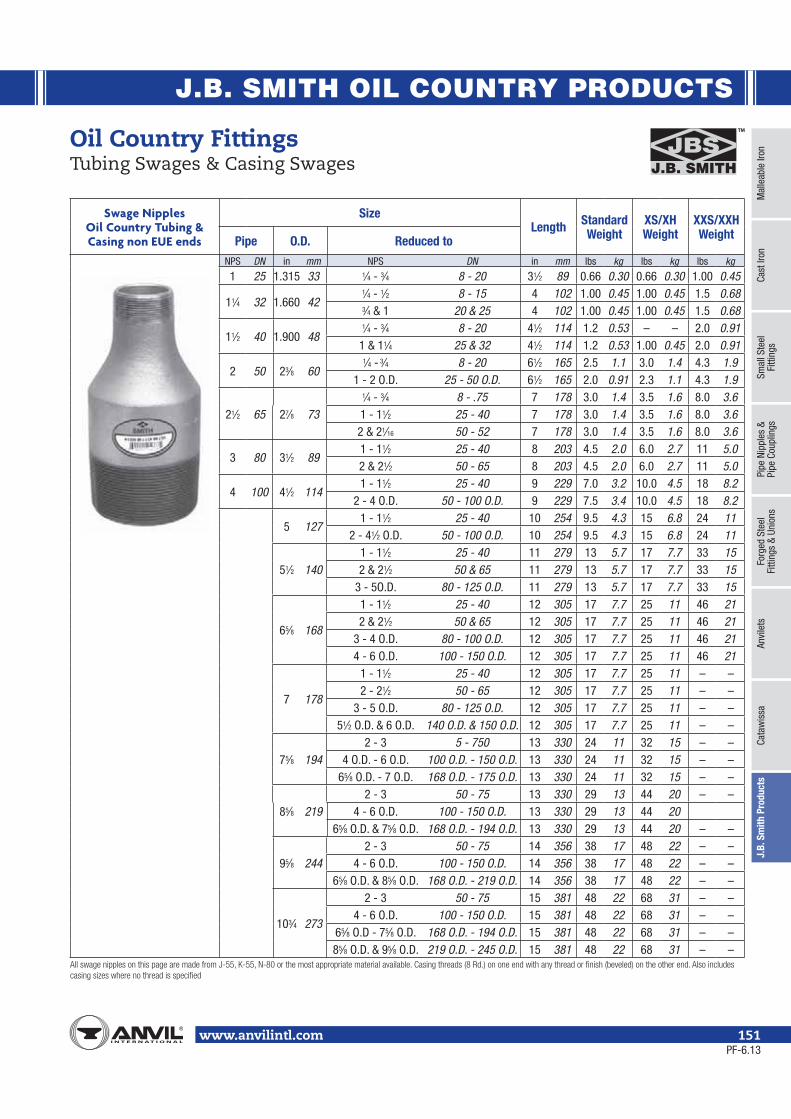
J.B. SMITH OIL COUNTRY PRODUCTS
Mal
leab
le Ir
onCa
st Ir
onSm
all S
teel
Fi
tting
sPi
pe N
ippl
es &
Pipe
Cou
plin
gsFo
rged
Ste
elFi
tting
s &
Unio
nsAn
vile
tsCa
taw
issa
J.B.
Sm
ith P
rodu
cts
www.anvilintl.com 151
Swage Nipples Oil Country Tubing &Casing non EUE ends
SizeLength Standard
WeightXS/XHWeight
XXS/XXHWeightPipe O.D. Reduced to
NPS DN in mm NPS DN in mm lbs kg lbs kg lbs kg
1 25 1.315 33 1⁄4 - 3⁄4 8 - 20 31⁄2 89 0.66 0.30 0.66 0.30 1.00 0.45
11⁄4 32 1.660 421⁄4 - 1⁄2 8 - 15 4 102 1.00 0.45 1.00 0.45 1.5 0.683⁄4 & 1 20 & 25 4 102 1.00 0.45 1.00 0.45 1.5 0.68
11⁄2 40 1.900 481⁄4 - 3⁄4 8 - 20 41⁄2 114 1.2 0.53 – – 2.0 0.91
1 & 11⁄4 25 & 32 41⁄2 114 1.2 0.53 1.00 0.45 2.0 0.91
2 50 23⁄8 601⁄4 - 3⁄4 8 - 20 61⁄2 165 2.5 1.1 3.0 1.4 4.3 1.9
1 - 2 O.D. 25 - 50 O.D. 61⁄2 165 2.0 0.91 2.3 1.1 4.3 1.9
21⁄2 65 27⁄8 73
1⁄4 - 3⁄4 8 - .75 7 178 3.0 1.4 3.5 1.6 8.0 3.61 - 11⁄2 25 - 40 7 178 3.0 1.4 3.5 1.6 8.0 3.62 & 21⁄16 50 - 52 7 178 3.0 1.4 3.5 1.6 8.0 3.6
3 80 31⁄2 891 - 11⁄2 25 - 40 8 203 4.5 2.0 6.0 2.7 11 5.02 & 21⁄2 50 - 65 8 203 4.5 2.0 6.0 2.7 11 5.0
4 100 41⁄2 1141 - 11⁄2 25 - 40 9 229 7.0 3.2 10.0 4.5 18 8.2
2 - 4 O.D. 50 - 100 O.D. 9 229 7.5 3.4 10.0 4.5 18 8.2
5 1271 - 11⁄2 25 - 40 10 254 9.5 4.3 15 6.8 24 11
2 - 41⁄2 O.D. 50 - 100 O.D. 10 254 9.5 4.3 15 6.8 24 11
51⁄2 1401 - 11⁄2 25 - 40 11 279 13 5.7 17 7.7 33 152 & 21⁄2 50 & 65 11 279 13 5.7 17 7.7 33 15
3 - 5O.D. 80 - 125 O.D. 11 279 13 5.7 17 7.7 33 15
65⁄8 168
1 - 11⁄2 25 - 40 12 305 17 7.7 25 11 46 212 & 21⁄2 50 & 65 12 305 17 7.7 25 11 46 21
3 - 4 O.D. 80 - 100 O.D. 12 305 17 7.7 25 11 46 214 - 6 O.D. 100 - 150 O.D. 12 305 17 7.7 25 11 46 21
7 178
1 - 11⁄2 25 - 40 12 305 17 7.7 25 11 – –2 - 21⁄2 50 - 65 12 305 17 7.7 25 11 – –
3 - 5 O.D. 80 - 125 O.D. 12 305 17 7.7 25 11 – –51⁄2 O.D. & 6 O.D. 140 O.D. & 150 O.D. 12 305 17 7.7 25 11 – –
75⁄8 1942 - 3 5 - 750 13 330 24 11 32 15 – –
4 O.D. - 6 O.D. 100 O.D. - 150 O.D. 13 330 24 11 32 15 – –65⁄8 O.D. - 7 O.D. 168 O.D. - 175 O.D. 13 330 24 11 32 15 – –
85⁄8 2192 - 3 50 - 75 13 330 29 13 44 20 – –
4 - 6 O.D. 100 - 150 O.D. 13 330 29 13 44 2065⁄8 O.D. & 75⁄8 O.D. 168 O.D. - 194 O.D. 13 330 29 13 44 20 – –
95⁄8 2442 - 3 50 - 75 14 356 38 17 48 22 – –
4 - 6 O.D. 100 - 150 O.D. 14 356 38 17 48 22 – –65⁄8 O.D. & 85⁄8 O.D. 168 O.D. - 219 O.D. 14 356 38 17 48 22 – –
103⁄4 273
2 - 3 50 - 75 15 381 48 22 68 31 – –4 - 6 O.D. 100 - 150 O.D. 15 381 48 22 68 31 – –
65⁄8 O.D - 75⁄8 O.D. 168 O.D. - 194 O.D. 15 381 48 22 68 31 – –85⁄8 O.D. & 95⁄8 O.D. 219 O.D. - 245 O.D. 15 381 48 22 68 31 – –
Oil Country FittingsTubing Swages & Casing Swages
PF-6.13

J.B. SMITH OIL COUNTRY PRODUCTS
www.anvilintl.com152
Oil Country FittingsBull Plugs
Casing Bull Plugs• 4 1⁄2" O.D. – 10 3⁄4" O.D. (114 O.D. – 273 O.D. DN) casing bull plugs available with all current API threads or beveled for welding• Casing bull plugs available in standard, extra heavy or double extra
Tubing Bull Plugs
SizeLength Standard
WeightXS/XH Weight
XXS/XXH & Sch. 160
WeightPipe API or O.D.
NPS DN in mm in mm lbs kg lbs kg lbs kg3⁄4 EUE 20 3 76 1.5 0.68 0.50 0.23 — —
1 25 1.315 33 3 76 1.5 0.68 0.66 0.30 — —1 EUE 25 3 76 1.5 0.68 — — — —
11⁄4 32 1.660 42 31⁄4 83 1.5 0.68 1.00 0.45 — —11⁄4 EUE 32 31⁄4 83 1.5 0.68 — — — —
11⁄2 40 1.900 48 31⁄2 89 1.5 0.68 1.1 0.48 — —11⁄2 EUE 40 31⁄2 89 2.0 0.91 2.3 1.0 — —
2 50 23⁄8 60 4 102 2.0 0.91 3.0 1.4 4.3 1.92 EUE 50 5 127 3.5 1.6 4.0 1.8 9.0 4.1
21⁄2 65 27⁄8 73 5 127 3.0 1.4 3.5 1.6 8.0 3.621⁄2 EUE 65 51⁄2 140 4.3 1.9 6.0 2.7 14 6.4
3 80 31⁄2 89 6 152 4.5 2.0 5.0 2.3 11 5.03 EUE 80 61⁄2 165 10.0 4.5 15 6.8 25 11
Casing Bull Plugs API or O.D. Length Standard Weight XS/XH Weight XXS/XXH &
Sch. 160 Weightin mm in mm lbs kg lbs kg lbs kg
41⁄2 114 7 178 7.5 3.4 10.0 4.5 18 8.25 127 8 203 9.5 4.3 15 6.8 24 11
51⁄2 140 81⁄2 216 13 5.7 17 7.7 33 1565⁄8 168 10 254 17 7.7 25 11 46 217 178 10 254 17 7.7 25 11 50 23
75⁄8 194 11 279 24 11 32 15 53 2485⁄8 219 11 279 29 13 44 20 78 3595⁄8 244 12 305 36 16 47 21 76 34103⁄4 273 13 330 41 18 56 25 85 39
API Bull PlugsFemale
SizeLength
SizeLength
Tubing Size O.D. Tubing Size O.D.in mm in mm in mm in mm in mm in mm3⁄4 20 1.313 33 33⁄16 81 2 50 2.875 73 41⁄4 108
3⁄4 EUE 20 1.660 42 31⁄4 83 2 EUE 50 3.063 78 47⁄8 124
1 25 1.660 42 31⁄4 83 21⁄2 65 3.500 89 51⁄8 130
1 EUE 25 1.900 48 31⁄2 89 21⁄2 EUE 65 3.668 93 51⁄4 133
11⁄4 32 2.054 52 31⁄2 89 3 80 4.250 108 55⁄8 143
11⁄4 EUE 32 2.200 56 33⁄4 95 3 EUE 80 4.500 114 53⁄4 146
11⁄2 40 2.200 56 33⁄4 95 4 100 5.200 132 61⁄8 156
11⁄2 EUE 40 2.500 64 37⁄8 98 4 EUE 100 5.563 141 61⁄4 159
PF-6.13

J.B. SMITH OIL COUNTRY PRODUCTS
Mal
leab
le Ir
onCa
st Ir
onSm
all S
teel
Fi
tting
sPi
pe N
ippl
es &
Pipe
Cou
plin
gsFo
rged
Ste
elFi
tting
s &
Unio
nsAn
vile
tsCa
taw
issa
J.B.
Sm
ith P
rodu
cts
www.anvilintl.com 153
Oil Country FittingsBell Nipples and Tubing Nipples
Tubing Nipples Standard Weight
Size End ConnectionNPS DN
18" and shorter upset and non-upset 1 25
Upset A.P.I. Thds, One or Both Ends
Non-upset (Regular)
11⁄4 32Upset A.P.I. Thds, One or Both Ends
Non-upset (Regular)
11⁄2 40Upset A.P.I. Thds, One or Both Ends
Non-upset (Regular)
2 50Upset A.P.I. Thds, One or Both Ends
Non-upset (Regular)
21⁄2 65Upset A.P.I. Thds, One or Both Ends
Non-upset (Regular)
3 80Upset A.P.I. Thds, One or Both Ends
Non-upset (Regular)
4 100Upset A.P.I. Thds, One or Both Ends
Non-upset (Regular)
Tubing Nipples Extra Heavy Weight
Size End ConnectionNPS DN
18" and shorter upset and non-upset 1 25
Upset A.P.I. Thds, One or Both Ends
Non-upset (Regular)
11⁄4 32Upset A.P.I. Thds, One or Both Ends
Non-upset (Regular)
11⁄2 40Upset A.P.I. Thds, One or Both Ends
Non-upset (Regular)
2 50Upset A.P.I. Thds, One or Both Ends
Non-upset (Regular)
21⁄2 65Upset A.P.I. Thds, One or Both Ends
Non-upset (Regular)
3 80Upset A.P.I. Thds, One or Both Ends
Non-upset (Regular)
4 100Upset A.P.I. Thds, One or Both Ends
Non-upset (Regular)
Tubing Nipples• Tubing Nominal Sizes 1 – 4 (25 – 100 DN) upset and non-upset ends• Lengths are 4" – 18" (102mm–457mm)• Tubing nipples are available with any combination of API 5B threads (8Rd, l0Rd, 11 1⁄2 V, 8V, etc) and are available in grades J-55,
K-55, N-80 and L-80 API 5CT material grades
• Wall thicknesses available: standard, extra heavy, double extra heavy• For different grades of material (stainless, brass, etc.) and different threads, consult factory
Standard and XH Weight available in standard lengths 4", 6", 8", 10", 12", 14", 16", 18." Also, available in non-standard lengths.
Bell Nipples• J.B. Smith manufactures a full line of Bell Nipples in sizes 41/2" - 85/8" NPS from K55 raw materials• Bell Nipples are 8 RD threaded (short or long) by slip joint end connections.• Full traceability and mill certification available upon request at time of order.
Bell Nipples O.D. Size Weight
NPS DN lbs kg
41⁄2 114 4.5 2.0
51⁄2 140 9.0 4.1
7 175 13.0 6.0
85⁄8 219 15.0 6.8
PF-6.13

J.B. SMITH OIL COUNTRY PRODUCTS
www.anvilintl.com154
Oil Country Casing Nipples Size O.D. Weight Per Foot API Material
GradeNPS DN lbs kg
41⁄2 11410.5 4.8 K11.6 5.3 K-N-P
5 125
11.5 5.2 K13.0 5.9 K15.0 6.8 K-N-P18.0 8.2 N-P
51⁄2 140
14.0 6.4 K15.5 7.0 K17.0 7.7 K-N-P20.0 9.1 N-P
65⁄8 16820.0 9.1 K24.0 11 K-N-P28.0 13 N-P
7 175
20.0 9.1 K23.0 10 K-N26.0 12 K-N-P29.0 13 N-P
75⁄8 19426.4 12 K-N29.7 13 N-P
85⁄8 219
24.0 11 K32.0 15 K36.0 16 K-N44.0 20 N-P49.0 22 N-P
95⁄8 245
36.0 16 K40.0 18 K-N43.5 20 N-P47.0 21 N-P
103⁄4 27340.5 18 K45.5 21 K55.5 25 N-P
113⁄4 298 60.0 27 K
133⁄8 340
54.5 25 K61.0 28 K68.0 31 K72.0 33 K
16 40075.0 34 K84.0 38 K
Oil Country FittingsCasing Nipples
PF-6.13

J.B. SMITH OIL COUNTRY PRODUCTS
Mal
leab
le Ir
onCa
st Ir
onSm
all S
teel
Fi
tting
sPi
pe N
ippl
es &
Pipe
Cou
plin
gsFo
rged
Ste
elFi
tting
s &
Unio
nsAn
vile
tsCa
taw
issa
J.B.
Sm
ith P
rodu
cts
www.anvilintl.com 155
API Casing CouplingsShort Thread Casing O.D. Weight/100 Length of Round Thread
CouplingNPS DN lbs kg in mm
41⁄2 114 805 365 61⁄4 159
5 125 1018 462 61⁄2 165
51⁄2 140 1144 519 63⁄4 171
65⁄8 168 1997 906 71⁄4 184
7 175 1834 832 71⁄4 184
75⁄8 194 2693 1222 71⁄2 191
85⁄8 219 3558 1614 73⁄4 197
95⁄8 144 3951 1792 73⁄4 197
103⁄4 273 4553 2065 8 203
113⁄4 298 – – 8 203
133⁄8 340 5623 2551 8 203
16 400 7898 3582 9 229
20 500 9500 4309 9 229
API Casing CouplingsLong Thread Casing O.D. Weight/100 Length of Coupling
NPS DN lbs kg in mm
41⁄2 114 907 411 7 178
5 125 1256 570 73⁄4 197
51⁄2 140 1403 636 8 203
65⁄8 168 1829 830 83⁄4 222
7 175 2367 1074 9 229
75⁄8 194 3423 1553 91⁄4 235
85⁄8 219 4748 2154 10 254
95⁄8 244 5577 2530 101⁄2 267
103⁄4 273 6202 2813 101⁄2 267
133⁄8 340 7663 3476 101⁄2 267
Combination Couplings J-55 Size O.D
in in
2 23⁄8
21⁄2 27⁄8
3 3
4 4
Oil Country CouplingsCasing Couplings
PF-6.13

J.B. SMITH OIL COUNTRY PRODUCTS
www.anvilintl.com156
Special Clearance Tubing Couplings
Size Nominal Inches
Tubing O.D.
External UpsetLbs.
Per 100Actual O.D.
InchesJ-55 N-80 C-75 L-80
2" 23⁄8" POA POA POA 240 2.91
21⁄2" 27⁄8" POA POA POA 348 3.46
3" 31⁄2" POA POA POA 540 4.18
API Tubing CouplingsSize
Nominal Inches
Tubing O.D.
Non-Upset External Upset
J-55 N-80 Lbs. Per 100 J-55 N-80 C-75 Lbs.
Per 100
2" 23⁄8" POA POA 282 POA POA POA 342
21⁄2" 27⁄8" POA POA 515 POA POA POA 529
3" 31⁄2" POA POA 817 POA POA POA 902
31⁄2" 4" POA POA 957 POA POA POA 1,056
4 41⁄2" POA POA 1,076 POA POA POA 1,331
Oil Country CouplingsTubing Couplings
Sub Tubing Couplings J-55 Size Weight Each
2 EUE x 2 Reg 521⁄2 Reg x 2 Reg 521⁄2 Reg x 2 EUE 521⁄2 EUE x 2 Reg 821⁄2 EUE x 2 EUE 8
21⁄2 EUE x 21⁄2 Reg 73 Reg x 2 Reg 113 Reg x 2 EUE 11
3 Reg x 21⁄2 Reg 103 Reg x 21⁄2 EUE 103 EUE x 2 Reg 153 EUE x 2 EUE 14
3 EUE x 21⁄2 Reg 163 EUE x 21⁄2 EUE 153 EUE x 3 Reg 134 Reg x 3 Reg 104 Reg x 3 EUE 124 EUE x 3 Reg 114 EUE x 3 EUE 114 EUE x 4 Reg 10
PF-6.13

J.B. SMITH OIL COUNTRY PRODUCTS
Mal
leab
le Ir
onCa
st Ir
onSm
all S
teel
Fi
tting
sPi
pe N
ippl
es &
Pipe
Cou
plin
gsFo
rged
Ste
elFi
tting
s &
Unio
nsAn
vile
tsCa
taw
issa
J.B.
Sm
ith P
rodu
cts
www.anvilintl.com 157
• Chambers are available in 2" – 8" inch diameter and up to 2 feet long.
• Material is A106 Grade B seamless, unless otherwise specified.
• Solid, bored, or tapped Ends are available.
Phone: 713-928-5711Email: [email protected]
Chambers / Pressure Vessels
PF-6.13

www.anvilintl.com158
Coated Products
Anvil’s coated products protect pipes against the corrosive conditions found in oil and gas pipelines. They are effective on all grades of pipe, and can be used to coat malleable, cast iron, forged steel, and ductile metals.
Anvil provides two stock coatings, Scotchkote 134 and Corvel 1660, which are durable, reliable and field-tested. Scotchkote 134 is a fusion-bonded epoxy coating designed to protect metal surfaces from corrosion. It is resistant to wastewater, corrosive acids, hydrocarbons, harsh chemicals, brine, and saltwater.
Corvel 1660 is specially designed to protect the inside diameter of tubular goods in applications such as fittings, valves, drill pipes, sucker rods, and metering systems. Corvel 1660 is resistant to H2S, CO2, harsh chemicals, brine, and salt water.
Anvil also offers a range of specialty coatings, available upon request, including nickel coating, chrome plating, Teflon coating, Nap-Guard coating, and powder coating.
COATED PRODUCTS
PF-6.13

www.anvilintl.com 159
1) Inspect both male and female components prior to assembly.• Threads should be free from mechanical damage, dirt, chips and excess cutting oil.• Clean or replace components as necessary.
2) Application of thread sealant• Use a thread sealant that is fast drying, sets-up to a semi hard condition and is vibration resistant. Alternately, an anaerobic
sealant may be utilized.• Thoroughly mix the thread sealant prior to application.• Apply a thick even coat to the male threads only. Best application is achieved with a brush stiff enough to force sealant down
to the root of the threads.
3) Joint Makeup• For sizes up to and including 2" pipe, wrench tight makeup is considered three full turns past handtight. Handtight engagement
for 1⁄2" through 2" thread varies from 41⁄2 turns to 5 turns.• For 2 1⁄2" through 4" sizes, wrench tight makeup is considered two full turns past handtight. Handtight engagement for 2 1⁄2"
through 4" thread varies from 51⁄2 turns to 63⁄4 turns.
General Assembly of Threaded Fittings
PF-11.13

www.anvilintl.com160
Conditions and Terms of Sale
1. CONTROLLING PROVISIONS: These terms and conditions shall control with respect to any purchase order or sale of Seller’s products. No waiver, alteration or modification of these terms and conditions whether on Buyer’s purchase order or otherwise shall be valid unless the waiver, alteration or modification is specifically accepted in writing and signed by an authorized representative of Seller.
2. DELIVERY: Seller will make every effort to complete delivery of products as indicated on Seller’s acceptance of an order, but Seller assumes no responsibility or liability, and will accept no back-charge, for loss or damage due to delay or inability to deliver caused by acts of God, war, labor difficulties, accident, delays of carriers, by contractors or suppliers, inability to obtain materials, shortages of fuel and energy, or any other causes of any kind whatever beyond the control of Seller. Seller may terminate any contract of sale of its products without liability of any nature, by written notice to Buyer, in the event that the delay in delivery or performance resulting from any of the aforesaid causes shall continue for a period of sixty (60) days. Under no circumstances shall Seller be liable for any special or consequential damages or for loss, damage, or expense (whether or not based on negligence) directly or indirectly arising from delays or failure to give notice of delay.
3. WARRANTY: Seller warrants for one year from the date of shipment Seller’s manufactured products to the extent that Seller will replace those having defects in materials or workmanship when used for the purpose and in the manner which Seller recommends. If Seller’s examination shall disclose to its satisfaction that the products are defective, and an adjustment is required, the amount of such adjustment shall not exceed the net sales price of the defective products only and no allowance will be made for labor or expense of repairing or replacing defective products or workmanship or damage resulting from the same. Seller warrants the products which it sells of other manufacturers to the extent of the warranties of their respective makers. Where engineering design or fabrication work is supplied, buyer’s acceptance of Seller’s design or of delivery of work shall relieve Seller of all further obligation, other than as expressed in Seller’s product warranty. THIS IS SELLER’S SOLE WARRANTY. SELLER MAKES NO OTHER WARRANTY OF ANY KIND, EXPRESSED OR IMPLIED: and ALL IMPLIED WARRANTIES OF MERCHANTABILITY and FITNESS FOR A PARTICULAR PURPOSE WHICH EXCEED SELLER’S AFORE STATED OBLIGATION ARE HEREBY DISCLAIMED BY SELLER and EXCLUDED FROM THIS WARRANTY. Seller neither assumes, nor authorizes any person to assume for it, any other obligation in connection with the sale of its engineering designs or products. This warranty shall not apply to any products or parts of products which (a) have been repaired or altered outside of Seller’s factory, in any manner; or (b) have been subjected to misuse, negligence or accidents; or (c) have been used in a manner contrary to Seller’s instructions or recommendations. Seller shall not be responsible for design errors due to inaccurate or incomplete information supplied by Buyer or its representatives.
4. SELLER’S LIABILITY: Seller will not be liable for any loss, damage, cost of repairs, incidental or consequential damages of any kind, whether based upon warranty (except for the obligation accepted by Seller under “Warranty” above), contract or negligence arising in connection with the design, manufacture, sale, use or repair of the products or of the engineering designs supplied to Buyer.
5. RETURNS: Seller cannot accept return of any products unless its written permission has been first obtained, in which case same will be credited subject to the following: (a) All material returned must, on its arrival at Seller’s plant, be found to be in first-class condition; if not, cost of putting in saleable condition will be deducted from credit memoranda. (b) A handling charge deduction of twenty percent (20%) will be made from all credit memoranda issued for material returned. (c) Transportation charges, if not prepaid, will be deducted from credit memoranda.
6. SHIPMENTS: All products sent out will be carefully examined, counted and packed. The cost of any special packing or special handling caused by Buyer’s requirements or requests shall be added to the amount of the order. No claim for shortages will be allowed unless made in writing within ten (10) days of receipt of a shipment. Claims for products damaged or lost in transit should be made on the carrier, as Seller’s responsibility ceases, and title passes, on delivery to the carrier.
7. SPECIAL PRODUCTS: Orders covering special or non-standard products are not subject to cancellation except on such terms as Seller many specify on application.
8. PRICES and DESIGNS: Prices and designs are subject to change without notice. All prices are F.O.B. Point of Shipment, unless otherwise stated.
9. TAXES: The amount of any sales, excise or other taxes, if any, applicable to the products covered by this order, shall be added to the purchase price and shall be paid by Buyer unless Buyer provides Seller with an exemption certificate acceptable to the taxing authorities.
10. NUCLEAR PLANTS: Where the products, engineering design or fabrication is for nuclear plant applications, Buyer agrees: (a) to take all necessary steps to add Seller as an insured under the American Nuclear Insurers’ (ANI) pool and under the Mutual Atomic Energy Reinsurance Pool (MAERP) for property damage and liability insurance and if necessary steps could have been taken, but are not taken, Buyer shall hold Seller harmless against all such losses which could have been thus covered, (b) to hold Seller harmless with respect to any personal injury (or death), property damage or other loss in a nuclear incident which is caused directly or indirectly by defective design, material, or workmanship furnished by Seller and which is covered by insurance maintained by Buyer (or which could be so covered but with respect to which Buyer has elected to self-insure), and further agrees to waive subrogation by its carriers of such insurance against Seller, and (c) as to nuclear hazards for which Buyer cannot obtain insurance coverage, the liability of Seller for any personal injury (or death), property damage or other loss directly caused by defective design, material, or workmanship furnished by Seller shall not exceed the value of the material furnished by Seller at the time of the loss occurrence.
11. MINIMUM INVOICE: $25.00 plus transportation.
12. TERMS: Cash, net 30 days unless otherwise specified.
PF-6.13

www.anvilintl.com 161
Engineering Information 15.3
MULTIPLY BY TO OBTAINAtmosphere 0.001316 TorrsAtmospheres 76 Cms. of mercury" 29.92 Inches of mercury" 33.9 Feet of water" 14.7 Lbs./sq. inchBarrels—Oil 42 GallonsBarrels—Cement 376 Lbs.—cementBags or Sacks—Cement 94 Lbs—cementBoard—feet 144 sq. in. x 1 in Cubic in.British Thermal Units 777.5 Foot lbs." " " 0.0003927 Horsepower—hrs." " " 0.0002928 Kilowatt—hrs." " " 0.00001 ThermsB.T.U./min 12.96 Foot lbs./sec
0.02356 Horsepower" " 0.01757 Kilowatts" " 17.57 WattsCentimeters 0.3937 InchesCubic centimeters 0.00003531 Cubic ft." " 0.06102 Cubic inches" " 0.000001308 Cubic yards" " 0.0002642 Gallons" " 0.03381 Ounces (Fluid)Cubic Cm./min 0.002118 Cu. ft./hr. " " / " 0.0002641 Gal./min.Cubic feet 1728 Cubic in. " " 7.48052 GallonsCubic inches 0.0005787 Cubic feet " " 0.00002143 Cubic yards " " 0.004329 GallonsCubic meters 35.31 Cu. ft. " " 61.023 Cu. In. " " 1.308 Cu. yds. " " 264.2 GallonsCubic yards 27 Cu. ft.Degrees (angle) 60 Minutes" " 0.01745 Radians" " 3600 SecondsDegrees/sec 0.01745 Radians/sec." " 0.1667 Revolutions/min." / " 0.002778 Revolutions/sec.English Viscosity Units 14.88 PoisesFeet 30.48 Centimeters" 12 Inches" 0.3048 MetersFeet of water 0.0295 Atmosphere" " " 0.8826 In. of mercury
62.43 Lbs./sq. ft." " " 0.4335 Lbs./sq. in.Feet/sec 0.6818 Miles/hr.Foot lbs 0.001286 Br. Thermal Units " " 0.000000505 Horsepower hrs. " " 3.766E-07 Kilowatt hrs.Foot Ibs./min 0.001286 B.T.U./min. " " / " 0.01667 Ft. Ibs./sec. " " / " 0.0000303 Horsepower " " / " 0.0000266 KilowattsFoot lbs./sec 0.0717 B.T.U./min. " " / " 0.001818 Horsepower " " / " 0.001356 KilowattsGallons 3785 Cubic centimeters" 0.1337 Cubic feet" 231 Cubic inchesGallons (Imperial) 1.20095 U.S. gallons" (U.S.) 0.83267 Imperial gallonsGallons water 8.3453 Pounds of waterGallons/min 0.002228 Cu. ft./sec." / " 8.0208 Cu. ft./hr.Grams 0.03527 Ounces" 0.002205 PoundsGrams/cu. cm 62.43 Pounds/cu. ft." / " " 0.03613 Pounds/cu.in.Horsepower 42.44 B.T.U./min." 33000 Ft. Ibs./min." 0.55 Ft. Ibs./sec.
0.7457 KilowattsHorsepower (boiler) 33,479 . B.T.U./hr." " 9.803 Kilowatts
MULTIPLY BY TO OBTAINHorsepower hours 0.2547 British Thermal Units" " 7457 Kilowatt hoursInches 2.54 CentimetersInches of mercury 0.03342 Atmospheres" " " 1.133 Ft. of water" " " 70.73 Lbs./sq. ft." " " 0.4912 Lbs./sq. in.Inches of water 0.002458 Atmospheres" " " 0.07355 Inches of mercury " " " 5.202 Lbs./sq. ft." " " 0.03613 Lbs./sq. in." " " 0.5781 Ounces/sq.in.Kilograms 2.205 Lbs.Kgs./meter 0.672 Lbs./ft.Kgs./sq. meter 0.003281 Feet of water" / " " 0.2048 Lbs./sq. ft." /" " 0.001422 Lbs./sq. in.Kilometers 3281 Feet" 0.6214 Miles" 0.1094 YardsKilometers/hr 27.78 Centimeters/sec." /" 54.68 Feet/min." /" 0.9113 Feet/sec." /" 0.6214 Miles/hr.Kilowatts 56.92 B.T.Units/min." 44250 Ft. Ibs./min." 737.6 Ft. Ibs./sec." 1.341 Horsepower" 0.1 WattsKilowatt hrs 0.3415 B.T.U." " 0.000002655 Ft. lbs." " 1.341 Horsepower-hrs.Liters 0.03531 Cu. ft." 61.02 Cu. in." 0.2642 GallonsMeters 100 Centimeters" 3.281 Feet" 39.37 Inches" 1.094 YardsMeters/sec 196.8 Ft./min.Millimeters 0.1 Centimeters" 0.03937 InchesOunces . 437.5 Grains" 28.349527 Grams" 0.0625 PoundsPounds . 16 Ounces" 7 Grains" 453.5924 GramsPounds of water 0.01602 Cu. ft." " " 27.68 Cu. in." " " 0.1198 GallonsPounds/cu. ft 0.0005787 Lbs./cu. in.Pounds/cu. in 1728 Lbs./cu. ft.Radians 57.3 Degrees" 0.3438 Minutes" 0.637 QuadrantsRadians / sec 57.3 Degrees/sec." / " 0.1592 Revolutions/sec." / " 9.549 Revolutions/min.Revolutions 360 Degrees" 4 Quadrants" 6.283 RadiansRevolutions/min 6 Degrees/sec" / " 0.1047 Radians/sec./ " 0.01667 Revolutions/sec.Temp. (°C) +273 1 Abs. temp. Co" +17.78 1.8 Temp. (°F)Temp. (°F) +460 1 Abs. temp. (°F)" -32 39942 Temp. (°C)Torr 760 AtmospheresTorr 1 mm HgWatts 0.05692 B.T. Units/min." 44.26 Ft. Ibs./min." 0.001341 Horsepower" 0.01 KilowattsYards 91.44 Centimeters" 3 Feet" 36 Inches" 0.9144 Meters
PF-6.13

www.anvilintl.com162
Figure Number Index
FIGURE NO. PAGE3L S1A 139
100/100C 126200/200C 127-128
206 129-130202 130211 131300 131301 132336 85337 86346 87347 87348 88349 89350 89351 37352 39
356/356A/356R 38358 40359 40-44360 45361 45366 46367 47368 48370 52371 37379 89380 51381 51383 35, 49-50385 35, 50387 51388 51389 51390 32, 51400 132-133421 52424 52425 53426 53459 33463 33551 33552 34
FIGURE NO. PAGE554 33600 133602 134-135607 135
701/701R 55702/702A 55
703 55705 56706 56707 56708 56718 58719 58722 58723 58726 59727 59729 59730 59731 60734 60735 60736 60744 61752 61753 61754 61801 63802 63803 64
804/804R 64805 65808 65811 66812 67821 68823 68825 69826 69832 34
1002 136-1371011 701016 711018 701021 73
FIGURE NO. PAGE1025 721030 72
1101/1101R 181102 191103 191104 201105 20
1105R 21-231106 241107 241108 241119 251121 251124 251125 261133 271134 271138 271160 28
1161/1161R 281162 291163 32
1164/1164R 29-301165 301166 311167 311170 291190 271502 1381538 742101 912102 912103 922104 922111 932112 932113 942114 932115 942116 942117 952118 962119 952120 962121 110
FIGURE NO. PAGE2122 1102125 1142126 1142127 1152128 1152131 972132 972133 982134 972135 982136 982137 992138 1002139 1112140 1112141 992142 1102143 1002150 1012151 1012152 1022153 1022158 1032154 1032155 1042156 1042157 1052159 112-1132170 1062171 1062172 1072173 1072174 1082175 1082176 1092177 1092178 1072179 112-113
J-3300 32S1A 139
PF-6.13

B R A N D S O F A N V I L I N T E R N AT I O N A L
North Alabama PipeFounded in 1983, NAP is a manufacturer of fabrication equipment, including automatic welders, plasma cut-off equipment, hole cutting equipment, make-on machines and pipe threaders. NAP, innovators of pipe fabrication equipment.
Anvil® product lines include malleable and cast iron fittings, unions and flanges; seamless and welded steel pipe nipples; steel pipe couplings; universal anvilets; forged steel fittings and unions; pipe hangers and supports; threaded rod; and engineered hangers.
The Gruvlok® product line consists of couplings for grooved and plain-end fittings, butterfly valves and check valves; flanges; pump protection components; pipe grooving tools; as well as copper and stainless steel system components.
Anvil-Strut™ products include a complete line of channel in stock lengths of 10 and 20 feet, with custom lengths available upon request. A variety of fittings and accessories are also offered. All products can be ordered in an assortment of finishes and material choices including SupR-Green™, Zinc Trivalent Chromium, pre-galvanized, hot-dipped galvanized, electro-galvanized, aluminum, plain, and stainless steel.
JB Smith™ is the leading manufacturer of oil country tubular fittings, swages and bull plugs – all meeting API specifications. Offering tubing nipples, casing nipples as well as a full line of traditional line pipe and oil country threads in every schedule, JB Smith is the resource for all your oilfield needs.
Catawissa™ NACE and API approved wing unions for Standard Service are offered in non-pressure seal ends as well as threaded and butt weld, and are interchangeable with most leading union manufacturers. Fully traceable and available with complete mill certifications, Catawissa’s oilfield wing union product line includes the standard ball-and-cone design plus our unique Figure 300 Flat Face design, where space and pipe line separation are a consideration.
The SPF/Anvil™ product line includes a variety of internationally sourced products such as grooved couplings, fittings, cast iron, malleable iron and ductile iron threaded fittings, steel pipe nipples, as well as tee-lets.
The Merit® product line includes a variety of tee-lets and drop nipples for fire protection applications. Most Merit products are UL/ULC Listed, FM Approved, and rated from 175 to 300 psi.
Steel pipe nipples and steel pipe couplings are manufactured in accordance with the ASTM A733 Standard Specification for Welded and Seamless Carbon Steel and Stainless Steel Pipe Nipples. Steel pipe couplings are manufactured in accordance with the ASTM A865 Standard Specification for Threaded Couplings, Steel, Black or Zinc-Coated (Galvanized) Welded or Seamless, for Use in Steel Pipe Joints. API couplings are manufactured in accordance with the API Specification for line pipe.
Canvil® manufactures low pressure hexagon reducer bushings, as well as plugs and hex caps up to 1” in diameter in various finishes including Oil Treat, Phosphate and Electro Galvanized. In addition, Canvil manufactures A105 hex or round material in class 3000 and 6000 pound, forged steel couplings and bar stock products offered as either as normalized (A105N) or non-normalized (A105) that are fully traceable for mechanicals and chemistry through our MTR program.
Anvil EPS-Engineered Pipe Supports are products used to support piping systems under thermal, seismic, and other dynamic loading conditions. The product line encompasses variable spring hangers, constant supports, sway struts and snubbers as well as standard and special design clamps. Anvil EPS brings the highest quality products and innovative engineering solutions to common and uncommon piping system problems.

CORPORATE OFFICES2 Holland Way
Exeter, NH 03833
Tel: 603-418-2800
Fax: 603-418-2833
E-mail: [email protected]
U.S. REGIONAL SERVICE CENTERSNorthern RegionRegional Distribution & Customer Service Center
7979 W. 183rd Street, Tinley Park, IL 60477
Tel: 708-885-3000
Fax: 708-534-5441
Toll Free: 1-800-301-2701
Southern RegionRegional Distribution & Customer Service Center
1401 Valley View Lane, Suite 150, Irving, TX 75061
Tel: 972-871-1206
Fax: 972-641-8946
Toll Free: 1-800-451-4414
CANADA SERVICE CENTERAnvil International CanadaCustomer Service Center
390 Second Avenue, P.O. Box 40, Simcoe, Ontario N3Y 4K9
Tel: 519-426-4551
Fax: 519-426-5509
INTERNATIONAL SALESEurope and Middle East RegionRick van Meesen
Tel: +31-53-5725570
Fax: +31-53-5725579
Mexico, Puerto Rico and Latin America RegionInternational Customer Service
Tel: +1-708-885-3000
Fax: +1-708-534-5441
B U I L D I N G C O N N E C T I O N S T H A T L A S T
North Alabama Pipe
#010/Printed in USA/© Copyright 2013Revision Date: 10.10.13