etractorimplements.com · web viewvictory tractor implements. wood chipper user manual owner’s...
TRANSCRIPT

Victory Tractor ImplementsWOOD CHIPPER USER MANUAL
Owner’s Manual: BXH-5x10, BXH-7x12
1
Victory Tractor Implements Warranty BXH5x10 & BHX7x12 Wood Chipper Warranty
This Product is warranted to be free of defects in materials and workmanship under normal use and service for a period of one year from the date of purchase, when operated and

maintained in accordance with the operating and maintenance instructions supplied with this unit. This warranty does not cover misuse or negligence. Under no circumstances will the manufacturer be liable for any consequential damage or expenses of any kind, including loss of profit. The manufacturer is under no circumstances liable for tractor damage of any kind. The manufacturer is not liable for maintenance of the product.
This warranty is extended only to the original purchaser. Warranty is void if repairs are attempted by anyone other than an authorized Service Center.
If difficulties arise with the product, you should contact Victory Tractor Implements at the contact information below. Only this location is authorized to make repairs to the product or provide for the replacement of defective parts, which will be done at no charge within a reasonable time after the receipt of product. The complete unit or parts should be returned to Victory Tractor Implements. The customer may have to cover the return shipping expense and is responsible for avoiding damage from the transport. In-Transit Damage is not covered by warranty. Please include your purchase receipt with any claim and keep a copy for your own file.
The seller’s liability under warranty is limited to the repair of the product and/or replacement of parts and is provided to the purchaser in lieu of all other remedies including incidental and consequential charges. There are no warranties, expressed or implied other than those specified herein.
For the nearest agent please contact:
Centex Group Inc. dba Victory Tractor Implements 65 Pine Av., Suite 857, Long Beach, CA 90802, USAWebsite: www.etractorimplements.comTel.: 1-562-235-5725 e-mail: [email protected]
.
1 INTRODUCTION
Congratulations on your choice of a 3 Point Hitch
Wood Chipper to compliment your operation.
This equipment has been designed and
manufactured
to meet the needs of a discerning timber or
landscaping
industry.
Safe, efficient and trouble free operation of your
Wood Chipper requires that you and anyone else who
will be using or maintaining the chipper, read and
understand the Safety, Operation, Maintenance
Trouble
Shooting information contained within the Operator's
Manual.
This manual covers the 3 Point Hitch Wood
Chipper
BX42, BX62 and BX92. Use the Table of
Contents
or Index as a guide to locate required
information.
Keep this manual handy for frequent reference
and
to pass on to new operators or owners.
OPERATOR ORIENTATION - The directions
left,
right, front and rear, as mentioned throughout
this
manual, are determined when sitting in the
tractor
driver's seat and facing in the direction of travel.

2 SAFETY
SAFETY ALERT SYMBOL
This Safety Alert symbol means
ATTENTION! BECOME ALERT! YOUR
SAFETY IS INVOLVED!
The Safety Alert symbol identifies important
safety
messages on the 3 Point Hitch Wood Chipper and in
the manual. When you see this symbol, be alert to the
possibility of personal injury or death. Follow the
instructions in the safety message.
Why is SAFETY important to you?
3 Big ReasonsAccidents Disable and KillAccidents CostAccidents Can Be AvoidedSIGNALWORDS:Note the use of the signal words DANGER,
WARNING and CAUTION with the safety
messages.
The appropriate signal word for each message has
been
selected using the following guide-lines:
DANGER - Indicates an imminently hazardous
situation that, if not avoided, will result in death or
serious injury. This signal word is to be limited to the
most extreme situations typically for machine
components which, for functional purposes, cannot
be
guarded.
WARNING - Indicates a potentially hazardous
situation that, if not avoided, could result in death or
serious injury, and includes hazards that are exposed
when guards are removed. It may also be used to
alert
against unsafe practices.
CAUTION - Indicates a potentially hazardous
situation that, if not avoided, may result in minor or
moderate injury. It may also be used to alert against
unsafe practices.
SAFETY
YOU are responsible for the SAFE operation and
maintenance of your 3 Point Hitch Wood Chipper.

YOU must ensure that you and anyone else who is
going to use, maintain or work around the 3 Point
Hitch Wood Chipper be familiar with the using and
maintenance procedures and related SAFETY
information contained in this manual. This manual
will
take you step-by-step through your working day and
alerts you to all good safety practices that should be
used while using the 3 Point Hitch Wood Chipper.
Remember, YOU are the key to safety. Good safety
practices not only protect you but also the people
around you. Make these practices a working part of
your safety program. Be certain that EVERYONE
using this equipment is familiar with the
recommended
using and maintenance procedures and follows all the
safety precautions.
Most accidents can be prevented. Do not risk injury
or death by ignoring good safety practices.
• 3 Point Hitch Wood Chipper owners must give
operating instructions to operators or employees
before
allowing them to operate the machine, and at least
annually thereafter.
• The most important safety device on this
equipment is a SAFE operator. It is the operator’s
responsibility to read and understand ALL Safety and
Operating instructions in the manual and to follow
these. Most accidents can be avoided.
• A person who has not read and understood all
using and safety instructions is not qualified to use the
machine. An untrained operator exposes himself and
bystanders to possible serious injury or death.
• Do not modify the equipment in any way.
Unauthorized modification may impair the function
and/or safety and could affect the life of the
equipment.
• Think SAFETY! Work SAFELY!
2.1 GENERAL SAFETY
1. Read and understand the Operator’s Manual and
all safety signs before using,
maintaining, adjusting or
cleaning the 3 Point Hitch
Wood Chipper.
2. Have a first aid kit
available for use should the
need arise and know how to
use it.
3. Have a fire
extinguisher available for
use should the need arise
and know how to use it.
4. Do not allow riders.
5. Wear appropriate
protective gear. This list includes but is not limited
to:
- A hard hat
- Protective shoes with slip resistant soles
- Protective glasses, goggles or face shield
- Heavy gloves
- Wet weather gear
- Hearing Protection
- Respirator or filter mask
6. Install and secure all guards before starting.
7. Wear suitable ear
protection for prolonged
exposure to excessive
noise.
8. Turn machine off,
stop and disable engine, remove ignition key and
place
in your pocket, set park brake and wait for all
moving
parts to stop before servicing, adjusting, repairing or
unplugging.
9. Clear the area of people, especially small
children,
before using the unit.
10. Review safety related items annually with all
personnel who will operate or maintaining the 3
Point
Hitch Wood Chipper.
2.2 EQUIPMENTSAFETY
GUIDELINES
1. Safety of the operator and bystanders is one of the
main concerns in designing and developing
equipment.
However, every year many accidents occur which
could have been avoided by a few seconds of
thought
and a more careful approach to handling equipment.
You, the operator, can avoid many accidents by
observing the following precautions in this section.
To
avoid personal injury or death, study the following
precautions and insist those working with you, or for
you to follow them.
2. In order to provide a better view, certain
photographs or illustrations in this manual may
show
an assembly with a safety shield removed.
However,
equipment should never be used in this
condition. Keep
all shields in place. If shield removal becomes
necessary for repairs, replace the shield prior to
use.
3. Replace any safety sign or instruction sign that is
not readable or is missing. Location of such safety
signs is indicated in this manual.
4. Never use alcoholic beverages or drugs which can
hinder alertness or coordination while using this
equipment. Consult your doctor about using this
machine while taking prescription medications.
5. Under no circumstances should young children
be allowed to work with this equipment. Do not
allow persons to use or assemble this unit until they
have read this manual and have developed a
thorough understanding of the safety precautions
and of how it works. Review the safety instructions
with all users annually.
6. This equipment is dangerous to children and
persons unfamiliar with its operation. The operator
should be a responsible, properly trained and
physically able person familiar with machinery and
trained in this equipment's operations. If the elderly are
assisting with work, their physical limitations need to
be recognized and accommodated.
7. Never exceed the limits of a piece of machinery.
If its ability to do a job, or to do so safely, is in
question - DON'T TRY IT.
8. Do not modify the equipment in any way.
Unauthorized modification may result in serious
injury
or death and may impair the function and life of the
equipment.
9. In addition to the design and configuration of
this
implement, including Safety Signs and Safety
Equipment, hazard control and accident prevention
are
dependent upon the awareness, concern, prudence,
and
proper training of personnel involved in the
operation,
transport, maintenance, and storage of the machine.
Refer also to Safety Messages and operation
instruction
in each of the appropriate sections of the tractor and
machine manuals.
Pay close attention to the Safety Signs affixed to
the
tractor and the machine.
2.3 SAFETY TRAINING
1. Safety is a primary concern in the design and
manufacture of our products. Unfortunately, our
efforts
to provide safe equipment can be wiped out by a
single
careless act of an operator or bystander.
2. In addition to the design and configuration of
equipment, hazard control and accident prevention
are
dependent upon the awareness, concern,
prudence and
proper training of personnel involved in the
operation,
transport, maintenance and storage of this
equipment.
3. It has been said, "The
best safety feature is an
informed, careful operator."
We ask you to be that kind
of an operator. It is the
operator's responsibility to read and understand
ALL
Safety and Using instructions in the manual and
to
follow these. Accidents can be avoided.
4. Working with unfamiliar equipment can
lead
to careless injuries. Read this manual before
assembly or using, to acquaint yourself with the
machine. If this machine is used by any person
other than yourself, or is loaned or rented, it is the
machine owner's responsibility to make certain that
the operator, prior to using:
a. Reads and understands the operator's
manuals.
b. Is instructed in safe and proper use.
5. Know your controls and how to stop tractor and
machine quickly in an emergency. Read this manual
and the one provided with tractor.
6. Train all new personnel and review instructions
frequently with existing workers. Be certain only a
properly trained and physically able person will use
the
machinery. A person who has not read and
understood
all using and safety instructions is not qualified to use
the machine. An untrained operator exposes himself
and bystanders to possible serious in- jury or death. If
the elderly are assisting with the work, their physical
limitations need to be recognized and accommodated.
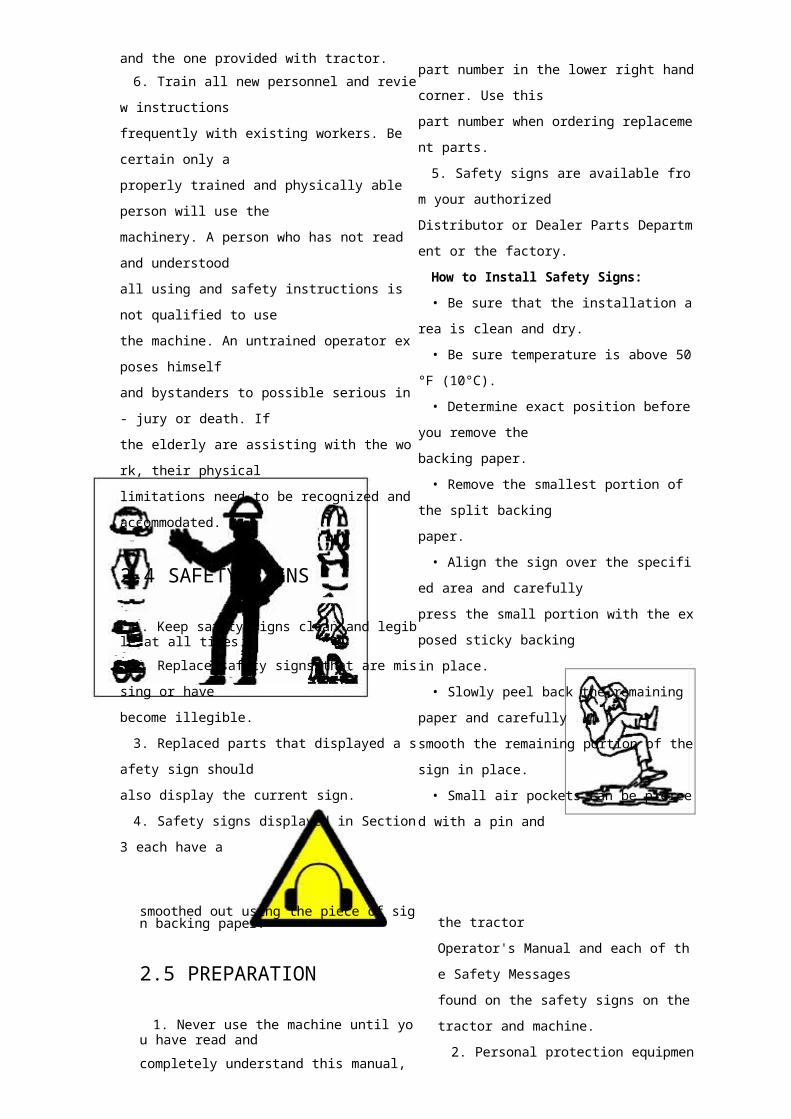
2.4 SAFETY SIGNS
1. Keep safety signs clean and legible at all times.
2. Replace safety signs that are missing or have
become illegible.
3. Replaced parts that displayed a safety sign
should
also display the current sign.
4. Safety signs displayed in Section 3 each have a
part number in the lower right hand corner. Use this
part number when ordering replacement parts.
5. Safety signs are available from your authorized
Distributor or Dealer Parts Department or the factory.
How to Install Safety Signs:
• Be sure that the installation area is clean and dry.
• Be sure temperature is above 50°F (10°C).
• Determine exact position before you remove the
backing paper.
• Remove the smallest portion of the split backing
paper.
• Align the sign over the specified area and
carefully
press the small portion with the exposed sticky
backing
in place.
• Slowly peel back the remaining paper and
carefully

smooth the remaining portion of the sign in place. • Small air pockets can be pierced with a pin and
smoothed out using the piece of sign backing paper.
2.5 PREPARATION
1. Never use the machine until you have read and
completely understand this manual, the tractor
Operator's Manual and each of the Safety Messages
found on the safety signs on the tractor and machine.
2. Personal protection equipment including hard
hat,
safety glasses, safety shoes, and gloves are
recommended during assembly, installation,
operation,
adjustment, maintaining, repairing, removal, cleaning,
or moving the unit. Do not allow long hair, loose
fitting
clothing or jewellery to be around equipment.
3. PROLONGED EXPOSURE TO LOUD
NOISE MAY CAUSE PERMANENT HEARING
LOSS!
Power equipment with
or without equipment
attached can often be
noisy enough to cause
permanent, partial hearing
loss. We recommend that you wear hearing protection
on a full-time basis if the noise in the Operator's
position exceeds 80db.
Noise over 85db on a long-term basis can cause
severe hearing loss. Noise over 90db adjacent to the
Operator over a long-term basis may cause permanent,
total hearing loss.
NOTE: Hearing loss from loud noise (from tractors,
chain saws, radios, and other such sources close to the
ear) is cumulative over a lifetime without hope of
natural recovery.
4. Clear working area of stones, branches or hidden
obstacles that might be hooked or snagged, causing
injury or damage.
5. Use only in daylight or good artificial light.
6. Be sure machine is properly mounted, adjusted
and in good operating condition.
7. Ensure that all safety shielding and safety signs
are properly installed and in good condition.
2.6 MAINTENANCE SAFETY
1. Good maintenance is your responsibility. Poor
maintenance is an invitation to trouble.
2. Follow good shop practices.
- Keep service area
clean and dry.
- Be sure electrical
outlets and tools are
properly grounded.
- Use adequate light
for the job at hand.
3. Make sure there is plenty of ventilation. Never
operate the engine of the towing vehicle in a closed
building. The exhaust fumes may cause asphyxiation.
4. Before working on this machine, shut off the
engine, set the brake, and turn fuel valve off.
5. Never work under equipment unless it is
blocked
securely.
6. Always use personal protection devices such as
eye, hand and hearing protectors, when performing
any
service or maintenance work. Use heavy or leather
gloves when handling blades.
7. Where replacement parts are necessary for
periodic maintenance and servicing, genuine factory
replacement parts must be used to restore your
equipment to original specifications.
The manufacturer will not be responsible for
injuries
or damages caused by use of unapproved parts and/
or
accessories.
8. A fire extinguisher and first aid kit should be
kept
readily accessible while performing maintenance on
this equipment.
hazardous. There is no substitute for a cautious,
safe-minded operator who recognizes potential
hazards
and follows reasonable safety practices. The
manufacturer has designed this 3 Point Hitch Wood
Chipper to be used with all its safety equipment
properly attached, to minimize the chance of
accidents.
Study this manual to make sure you have all safety
equipment attached.
3. Close and secure rotor cover before operating.
4. Close and secure all guards, deflectors and
shields
before starting and operating.
5. Read and understand operator's manual before
starting. Review safety instructions annually.
6. Personal protection equipment including hearing
protection, hard hat, safety glasses, safety shoes, and
gloves are recommended during assembly,
installation,
operation, adjustment, maintaining,
repairing, removal,
or moving. Do not allow long hair, loose-fitting
clothing, or
9. Periodically tighten all bolts, nuts and screws and
check that all electrical and fuel connections are
properly secured to ensure unit is in a safe condition.
10. When completing a maintenance or service
function, make sure all safety shields and devices are
installed before placing unit in service.
2.7 OPERATING SAFETY
1. Please remember it is important that you read and
heed the safety signs on the 3 Point Hitch Wood
Chipper. Clean or replace all safety signs if they
cannot
be clearly read and understood.
They are there for your safety, as well as the
safety
of others. The safe use of this machine is strictly up
to
you, the operator.
2. All things with moving parts are potentially
jewellery to be around moving parts.
7. Keep hydraulic lines and fittings tight, in good
condition and free of leaks.
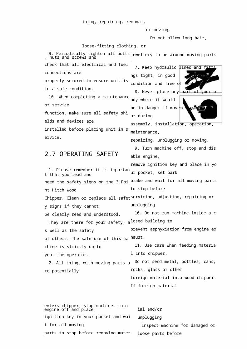
8. Never place any part of your body where it
would
be in danger if movement should occur during
assembly, installation, operation, maintenance,
repairing, unplugging or moving.
9. Turn machine off, stop and disable engine,
remove ignition key and place in your pocket, set
park
brake and wait for all moving parts to stop before
servicing, adjusting, repairing or unplugging.
10. Do not run machine inside a closed building to
prevent asphyxiation from engine exhaust.
11. Use care when feeding material into chipper.
Do not send metal, bottles, cans, rocks, glass or
other
foreign material into wood chipper. If foreign
material
enters chipper, stop machine, turn engine off and place
ignition key in your pocket and wait for all moving
parts to stop before removing material and/or
unplugging.
Inspect machine for damaged or loose parts before
resuming work.
12. Never use alcoholic beverages or drugs which
can hinder alertness or coordination while operating
this equipment. Consult your doctor about operating
this machine while taking prescription
medications.
13. Do not allow riders on this machine at any
time.
There is no safe place for any riders.
14. Never allow children or unauthorized
people to
operate or be around this machine.
15. Do not reach into rotor or feed hopper

openings
when the engine is running. Install and secure access
covers before starting engine.
16 Keep the working area clean and free of debris
to
prevent tripping. Operate only on level ground.
17 Do not point discharge at people, animals or
buildings. Rotor can expel wood chips fast enough to
cause injury.
18. Do not move or transport chipper when the
rotor
is turning.
19. Do not exceed a safe travel speed when
transporting.
2.8 HYDRAULIC SAFETY
1. Make sure that all the components in the hydraulic
system are kept in good condition and are clean.
2. Before applying pressure to the system, make
sure
all components are tight, and that lines, hoses and
couplings are not damaged.
3. Do not attempt any makeshift repairs to the
hydraulic lines, fittings or hoses by using tapes,
clamps
or cements. The hydraulic system operates under
extremely high pressure.
Such repairs will fail suddenly and create a
hazardous and unsafe condition.
4. Wear proper hand andeye protection whensearching for a highpressure hydraulic leak.Use a piece of wood orcardboard as a backstopinstead of hands to isolateand identify a leak.
5. If injured by a
concentrated
high-pressure stream of hydraulic fluid, seek medical
attention immediately. Serious infection or toxic
reaction can develop from hydraulic fluid piercing
the
skin surface.
6. Relieve pressure on hydraulic system before
maintaining or working on system.
2.9 STORAGE SAFETY
1. Store the unit in an area away from human
activity.
2. Do not children to play on or around the stored
machine.
3. Store the unit in a dry, level area. Support the
frame with planks if required.
2.10 TRANSPORT SAFETY
1. Comply with state and local laws governing safety
and transporting of machinery on public roads.
2. Check that all the lights, reflectors and other
lighting requirements are installed and in good
working
condition.
3. Do not exceed a safe travel speed. Slow down for
rough terrain and cornering.
4. Fold up and secure feed hopper before moving
or
transporting.
5. Be sure the machine is hitched positively to the
tractor and a retainer is used through the mounting
pins.
6. Do not drink and drive.
7. Be a safe and courteous driver. Always yield to
oncoming traffic in all situations, including narrow
bridges, intersections, etc. Watch for traffic when
operating near or crossing roadways.
8. Never allow riders on the machine.
3 ASSEMBLING
The machine comes from the factory in a shipping
configuration. Always use tools equipment and
forklifts of appropriate size and capacity for the job.
Always use 2 men when lifting, moving and
assembling the machine.
When the machine is shipped, follow this
procedure
when preparing for the customer:
1. Clear the area of bystanders especially small
children before starting.
2. Use a forklift to lift the pallet/machine from the
truck. Carry the load close to the ground.
3. Move the machine to the assembly area. Be sure
there is sufficient clearance to access the machine
from
all sides.
4. Cut the tie-down straps.
5. Lay-out components next to machine.
6. Use a forklift to raise and lift the frame.
7. Or alternatively attach a lifting device to the
lifting bracket on top of the frame.
8. Remove pallet and place machine on the ground.
9. Release feed hopper transport latch and lower
hopper into the working position. Stow anchor latch.
10. Tighten anchor bolts to their specified torque.
11. Connect the PTO driveline:
a. Raise the input shaft guard.
b. Check that the driveline telescopes easily and
that
the shield rotates freely.
c. Attach the driveline to the chipper input shaft by
depressing the lock pin, slide yoke over the shaft and
pushing on the yoke until the lock pin clicks into
position.
d. Lower the guard to cover the input shaft.
12. Depress handle on discharge chute latch and
turn
assembly to its desired position. Turn until latch seats
in its detent.
4 OPERATION
• Please remember it is important that you read the
operator's manual and heed the safety signs on the 3
Point Hitch Wood Chipper.
They are there for your safety, as well as the safety
of others. The safe use of this machine is strictly up
to
you, the operator.
• Personal protection equipment including hearing
protection, hard hat, safety glasses, safety shoes, and
gloves are recommended during assembly,
installation,
operation, adjustment, maintaining, repairing, or
plugging.
Do not allow long hair, loose-fitting clothing, or
jewellery to be around moving parts.
• Turn machine off, stop and disable engine,
remove
ignition key and place in your pocket, set park brake and wait for all moving parts to stop before servicing,
adjusting, repairing or unplugging.
• Do not run machine inside a closed building to
prevent asphyxiation from engine exhaust.
• Use care when feeding material into chipper. Do
not send metal, bottles, cans, rocks, glass or other
foreign material into wood chipper. If foreign
material
enters chipper, stop machine, turn engine off and
place
ignition key in your pocket and wait for all moving
parts to stop before removing material and/or
unplugging.
Inspect machine for damaged or loose parts before
resuming work.
• Never use alcoholic beverages or drugs which
can
hinder alertness or coordination while operating this
equipment. Consult your doctor about operating this
machine while taking prescription medications.
• Do not allow riders on this machine at any time.
There is no safe place for any riders.
• Never allow children or unauthorized people to
operate or be around this machine.
• Do not reach into rotor or feed hopper openings
when the engine is running. Install and secure access
covers before starting engine.
• Do not move or transport chipper when the rotor
is
turning.
• Do not exceed a safe travel speed when
transporting.
• Keep hydraulic lines and fittings tight, in good
condition and free of leaks.
• Keep the working area clean and free of debris
to
prevent tripping. Operate only on level ground.
• Do not point discharge at people, animals or
buildings. Rotor can expel wood chips fast
enough to
cause injury.

4.1 TO THE NEW OPERATOR OR
OWNER
The 3 Point Hitch Wood Chippers are designed to
chip or chop scrap lumber, small trees, brush, limbs
and other wood debris. The chipped material is fine
enough to be composted or used in a variety of ways.
It is the responsibility of the owner or operator to
read this manual and to train all other operators before
they start working with the machine. Follow all safety
instructions exactly.
Safety is everyone's business. By following
recommended procedures, a safe working environment
is provided for the operator, bystanders and the area
around the worksite.
Untrained operators are not qualified to use the
machine.
Follow all safety instructions exactly. Safety is
everyone's business. By following recommended
procedures, a safe working environment is provided for
the operator, bystanders and the area around the
worksite. Untrained operators are not qualified to
operate the machine.
Many features incorporated into this machine are
the
result of suggestions made by customers like you.
Read
this manual carefully to learn how to use the chipper
safely and how to set it to provide maximum field
efficiency. By following the using instructions in
conjunction with a good maintenance program, your
3
Point Hitch Wood Chipper will provide many years
of
trouble-free service.
4.2 MACHINE COMPONENTS
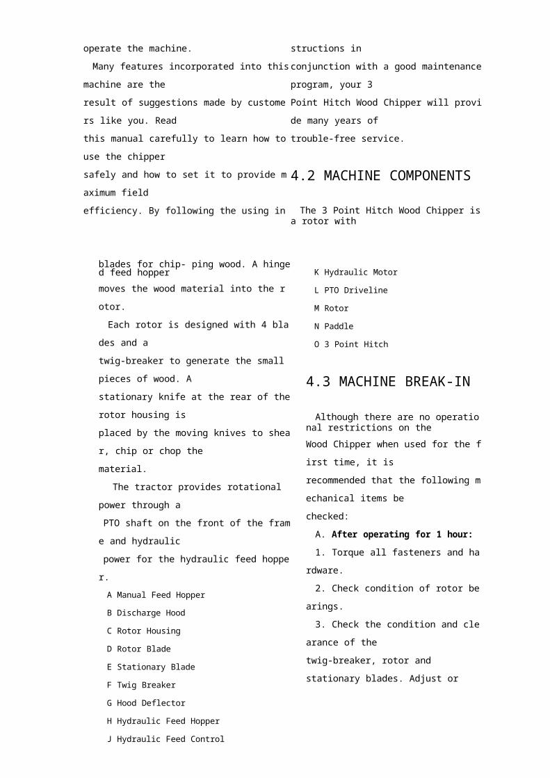
The 3 Point Hitch Wood Chipper is a rotor with
blades for chip- ping wood. A hinged feed hopper
moves the wood material into the rotor.
Each rotor is designed with 4 blades and a
twig-breaker to generate the small pieces of wood. A
stationary knife at the rear of the rotor housing is
placed by the moving knives to shear, chip or chop
the
material.
The tractor provides rotational power through a
PTO shaft on the front of the frame and hydraulic
power for the hydraulic feed hopper.
A Manual Feed Hopper
B Discharge Hood
C Rotor Housing
D Rotor Blade
E Stationary Blade
F Twig Breaker
G Hood Deflector
H Hydraulic Feed Hopper
J Hydraulic Feed Control
K Hydraulic Motor
L PTO Driveline
M Rotor
N Paddle
O 3 Point Hitch
4.3 MACHINE BREAK-IN
Although there are no operational restrictions on the
Wood Chipper when used for the first time, it is
recommended that the following mechanical
items be
checked:
A. After operating for 1 hour:
1. Torque all fasteners and hardware.
2. Check condition of rotor bearings.
3. Check the condition and clearance of the
twig-breaker, rotor and stationary blades. Adjust or
replace as required.
4. Check for entangled material. Remove all
entangled material before resuming work.
5. Lubricate all grease fittings.
B. After operating for 10 hours:
1. Repeat steps 1 through 5 listed above.
2. Go to the normal servicing and maintenance
schedule as defined in the Maintenance Section.
4.4PRE-OPERATION CHECKLIST
Efficient and safe operation of the 3 Point Hitch
Wood Chipper requires that each operator reads and
understands the using procedures and all related
safety
precautions outlined in this section. A pre-operation
checklist is provided for the operator. It is important
for both the personal safety and maintaining good
mechanical condition that this checklist is followed.
Before operating the Wood Chipper and each time
thereafter, the following areas should be checked off:
1. Lubricate the machine per the schedule outline
in
the Maintenance Section.
2. Check the rotor, blades and twig-breaker.
Remove
any twine, wire or other material that has become
entangled.
3. Check the condition and clearance of the twig
breaker, rotor and stationary blades. Adjust or replace
as required.
4. Check that all bearings turn freely. Replace any
that are rough or seized.
5. Make sure that all guards and shields are in
place,
secured and functioning as designed.
6. Check the condition of the curtain in the feed
hopper. It must be in good condition to prevent chips
from flying out.

4. 5 DRIVELINE DIMENSIONS
A PTO driveline is supplied with the machine. To
accompany the variety of 3.point hitch geometry
available today, the driveline can be too long for most
machines or too short for others. It is very important
that the driveline be free to telescope but not to
bottom
out when going through its working range. If the
driveline bottoms out, the bearings on both the
machine
and tractor PTO shaft will be overloaded and fail in a
short time.
1. To determine the proper length of the driveline,
follow this procedure:
a. Clear the area of bystanders, especially small
children.
b. Attach the chipper to the tractor (see section 5.8)
but do not attach the driveline.
c. Raise the machine until the input shaft is level
with the tractor PTO shaft.
d. Measure the dimension between the locking
grooves on the tractor PTO shaft and the machine
input
shaft.
e. Measure the same dimensions on the
compressed
driveline.
f. If the compressed driveline dimension
exceeds the
machine dimension, the driveline will have to be
cut.
2. When cutting the driveline, follow this
procedure:
a. Subtract the machine dimension (A) from the
uncut driveline dimension (B) or (B-A). This
dimension determines how much too long the driveline
is.
b. Add another inch (25 mm) to the dimension to
be
sure it doesn't bottom out, to determine (C) the cut
off
dimension.
c. Use a hacksaw to cut dimension (C) from both
ends. Cut both the plastic tubes and the metal cores.
d. Use a file to remove the burrs from the edges
that
were cut.
e. Assemble the 2 ends of the shaft.
f. Make sure the shaft can telescope freely. If it
does
not, separate the 2 parts and inspect for burrs or
cuttings on the shaft ends. Be sure it telescopes freely
before installing.
4.6 MOUNTING AND
UNHOOKING TRACTOR
When attaching chipper to a tractor, follow this
procedure:
1. Clear the area of bystanders, especially small
children.
2. Make sure there is enough room and clearance
to
safely back up to the chipper.
3. Place the tractor arms in their full sway
position.
4. Back up slowly and align the lower link arms to
the pins on the machine.
5. Mounting without a Quick Hitch.
a. Align the left lower link with the left chipper
pin.
IMPORTANTIt may be necessary to add weight to the lower lift
arms to bring them to the required height.
b. Insert the left pin through the ball and
install the
retainer.
c. Align the right arm to the pin by turning the
jackscrew on the arm.
d. Insert the right pin through the ball and
install the
retainer. Return the jackscrew to its starting
position.
Aligned
e. Remove the top pin and install the top link.
Use
the turnbuckle to align the top link. Insert the
pins and
install the retainers. Return the turnbuckle to its
original length and lock.
5. Mounting with a Quick Hitch.
a. Align the claws on the Quick Hitch slightly
below
the mounting pins on the chipper.
IMPORTANTIt may be necessary to add weight to the lower lift
arms to bring them to the required height.
b. Back up until the pins are above the claws.
c. Use the turnbuckle on the top link to adjust the
position of the top claw.
d. Raise the 3 point hitch until the pins seat in the
claws.
e. Be sure the retainers are released to hold the
pins
in the claws.
6. Set the 3 point hitch in the non-sway position
(see
tractor manual for details).
7. Install the PTO driveline:
NOTEBe sure the telescoping portion of the shaft is
greased and free of dirt.
a. Slide the collar back on the yoke, align the
splines
and slide the yoke on the tractor.
b. Release the collar and make sure the locking pin
clicks into position.
NOTEThe driveline should already have been cut to the
required length.
8. Connect the hydraulics:
a. Use a clean rag or paper towel to clean the dirt
from couplers on the hose ends and the tractor.
b. Connect the hoses to the tractor couplers. Be
sure
the couplers are securely seated.
c. Route and secure the hoses along the hitch with
clips, tape or plastic ties to prevent binding and
pinching. Be sure to provide slack for turning.
NOTEAlways connect to the hydraulic circuit with a
detent.
9. Slowly raise the machine through its working
range to make sure the telescoping portion of the
PTO
shaft doesn't bottom out.
10. Level the machine front and rear, and side to
side

using the jackscrew on the right arm and the turnbuckle
on the top link.
The chipper should always be level on the ground
in
its working position.
11. To unhook from the tractor, reverse the above
procedure. Always park the machine in a dry, level
area. If vandalism is a problem, remove the PTO
driveline and store in a secure place.
4. 7 CONTROLS
All controls are conveniently positioned next to
where the operator would stand when feeding the
machine to provide easy operation. Review this
section to familiarize yourself with the location
and
function of each control before starting.
1. Hydraulic Feed Control Lever:
This lever is positioned to extend around the
feed
hopper and provides access from all sides. It is
only
available when the chipper is equipped with the
optional hydraulic feed hopper.
Pull the control all the way out to engage the
feeding system. Push in slightly to the first detent
to
stop the feeding system.
Push the control all the way in to reverse the
feeding system.
NOTEUse the typical flow divider next to the control
valve
to set the feeding spread.
2. Deflector Position:
Each discharge hood is equipped with a
deflector
on the end to place the chips exactly where
desired.
There are 2 types available:
a. Manual Clamp (BX42):
The deflector is held in place by clamping
bolts on
each side. Loosen the clamps, move the deflector
and
tighten the clamps. Position as desired.

b. Spring-Loaded (BX62/BX92):
The deflector is spring-loaded up and held in
place by a chain. Release the chain from its anchor
bracket and move the deflector to its desired
position.
Secure chain in its anchor bracket.
3. PTO Control:
If you are not familiar with the location of the
PTO control on your tractor, review your tractor's
Operator's Manual. Always engage the PTO control
slowly when the engine is running at low idle RPM.
Disengage the PTO control slowly at low RPM to
allow the machine to slow and stop before engaging
the PTO brake. Remember the PTO drives the rotor.
When the PTO is engaged the rotor will also start to
turn.
4. Flow Control Valve:
This manually-set flow divider allows the
operator to set the flow through the circuit from 0%
to 100% by dumping the excess flow back to the
tractor. A scale on the face of the valve is
numbered
from 0 to 10 to define the percent of flow from 0
to
100% flowing into the circuit. The hydraulic feed
circuit is equipped with a flow divider so the
operator can adjust the feeding speed appropriate
for
the operating conditions. Loosen the lock and
move
the pointer arm to the desired position.
Tighten the lock bolt. Adjust in small
increments
as a small change can result in a large change to
feeding speed.
Manual Clamp Spring-Loaded
4. 8 FIELD OPERATION
• Please remember it is important that you read
the operator's manual and heed the safety signs
on
the 3 Point Hitch Wood Chipper. They are
there for
your safety, as well as the safety of others. The
safe
use of this machine is strictly up to you, the
operator.
• Personal protection equipment including
hearing
protection, hard hat, safety glasses, safety shoes,
and
gloves are recommended during assembly,
installation, operation, adjustment, maintaining,
repairing, or plugging.
Do not allow long hair, loose-fitting clothing, or
jewellery to be around moving parts.
• Turn machine off, stop and disable engine,
remove ignition key and place in your pocket, set
park brake and wait for all moving parts to stop
before servicing, adjusting, repairing or
unplugging.
• Do not run machine inside a closed building to
prevent asphyxiation from engine exhaust.
• Use care when feeding material into chipper.
Do not send metal, bottles, cans, rocks, glass or
other foreign material into wood chipper. If
foreign
material enters chipper, stop machine, turn engine
off and place ignition key in your pocket and wait
for all moving parts to stop before removing
material and/or unplugging. Inspect machine for
damaged or loose parts before resuming work.
• Never use alcoholic beverages or drugs which
can hinder alertness or coordination while
operating
this equipment. Consult your doctor about
operating
this machine while taking prescription
medications.
• Do not allow riders on this machine at any
time.
There is no safe place for any riders.
• Never allow children or unauthorized people
to
operate or be around this machine.
• Do not reach into rotor or feed hopper
openings
when the engine is running.
Install and secure access covers before starting
engine.
• Do not move or transport chipper when the
rotor
is turning.
• Do not exceed a safe travel speed when
transporting.
• Keep hydraulic lines and fittings tight, in good
condition and free of leaks.
• Keep the working area clean and free of debris
to prevent tripping. Operate only on level ground.
• Do not point discharge at people, animals or
buildings. Rotor can expel wood chips fast enough
to cause injury.
Although the 3 Point Hitch Wood Chipper is easy
to

use, each operator should review this section to
familiarize himself with the detailed safety and
operating procedures. When using this machine, follow
this procedure:
1. Clear the area of bystanders, especially small
children.
2. Review and follow the Pre-Operation Checklist.
3. Attach the machine to the tractor.
4. Drive to the work area and position at the
worksite.
5. Set park brake.
6. Stop engine.
7. Remove ignition key and place in your pocket.
8. Move the feed hopper down into its working
configuration and secure with the anchor nuts.
9. Turn discharge hood to its working position.
10. Starting the Machine:
a. Start the tractor engine.
b. Move the throttle to its low idle position.
c. With the engine at low idle, slowly engage the
PTO control.
d. Slowly increase the engine speed until the PTO
is
at rated speed.
e. With the manual feeding model, start feeding
material into the hopper.
f. With the hydraulic feeding model:
• Place the tractor hydraulic lever into its detent
position.
• Move the control lever into the feed position.
• Start feeding material into the hopper.
11. Stopping:
a. Stop feeding material into the hopper.
b. Place the hydraulic feed control in off/neutral.
c. Slow engine RPM.
d. Place hydraulic lever in its OFF position.
e. Disengage PTO.
f. Stop engine, remove ignition key and place in
your
pocket and wait for all moving parts to stop.
12. Emergency Stopping:

Stop tractor engine if an emergency occurs. Correct
emergency situation before starting engine and
resuming work.
a. Manual Feed:
• Slowly slide the wooden material into the feed
hopper and move it into the rotor.
• Do not push the material with a lot of force into the
rotor.
• Do not push the material too fast into the rotor.
Stop and slow down if the engine starts to slow down.
• Do not reach into the feed hopper further than the
curtain to be sure not to contact the blades on the rotor.
• Use a stick or branch to push any piece of material
into the rotor that does not move on its own and stops
in the hopper. Do not take a chance with getting your
hand caught in the rotor.
b. Hydraulic Feed:
• Slowly slide the wooden material into the feed
hopper until the roller grabs the material and move it
into the rotor.
• Use the flow divider on the side of the feed
hopper
to set the feeding speed.
• Do not reach into the feed hopper further than the
curtain to be sure not to contact the feed roller or the
blades on the rotor.
• Use a stick or branch to push any piece of
material
into the feed roller that does not move on its own and
stops in the hopper.
Do not take a chance with getting your hand
caught
in the feed roller.
14. Always wear personal protective equipment
(PPE) whenever operating the machine. This includes
but is not limited to protective shoes with slip
resistant
soles, protective goggles or face shield, heavy gloves,
hearing protection and protective clothing.
15. Do not place metal, bottles, cans, rocks, glass or
other solid material into the wood chipper. If
something like this gets into the machine, stop the
machine immediately for a detailed inspection. Stop
engine, remove ignition key and place in your pocket
and wait for all moving parts to stop before inspecting
or unplugging. Inspect machine for damaged or
loosened parts before resuming work.
16. Blades:
There are 2 types of blades used on the Wood
Chipper. They work together to cut, shear and shred
the
wood as it moves through the machine.
a. Rotor blades:
The rotor is equipped with 4 blades placed at 90°
to
each other to keep the rotor in balance. If one needs
to
be changed, the one opposite should be
changed.
b. Stationary blade:

Each machine is equipped with a stationary blade
that acts as a stop for the moving rotor blades.
Machine is shown with guard opened or rotor
cover opened for illustrative purposes only.
Do not operate machine with guard opened or
cover opened.
17. Clearance:
It is recommended that the clearance between the
rotor and stationary blades be set and maintained at
1/32 inch to obtain the best performance.
Use the stationary blade mounting bolts to set the
clearance as required.
Each machine is equipped with a twig breaker to
break up twigs or other long material as it moves
through the rotor compartment. Open the rotor cover
and check the condition of the breaker on a weekly
basis. Also check for any entangled material when
the
rotor cover is opened. Remove this material prior to
closing the cover and resuming work.
Machine is shown with guard opened or rotor
cover
opened for illustrative purposes only.
Do not operate machine with guard opened or
cover
opened.
Disassembled Double Mounting

19. Shear Pin: The PTO driveline is designed with a
shear pin at the input yoke to prevent overloading
the
drive system. Remove the broken parts from the
yoke
when the pin shears and replace with genuine parts.
The drive system is designed to function well
without failing the shear pin. If it does fail, generally
it
is being fed too fast or something very hard has been
jammed into the rotor or between the blades. Always
unplug the system and determine the cause of the
problem and correct it before resuming work.
Machine is shown with guard opened or rotor
compartment.
• Clean out the discharge area/rotor.
• Open the rotor cover and clean out the housing.
Be
sure to turn the rotor by hand to be sure there is
nothing
jammed between the rotor and stationary blades.
• Close, install and fold down all components
opened
to unplug. Tighten fasteners to their specified torque.
f. Check that everyone is clear of machine before
restarting engine.
g. Start the engine, engage the PTO and resume
working.
cover opened for illustrative purposes only.
Do not operate machine with guard opened orFeed Hopper Discharge
Hood
RNING
cover opened.
20. Unplugging:
Although the machine is designed to handle a
wide
variety of material without any problem,
occasionally it
plugs. When the machine plugs, follow this
procedure
to unplug:
a. Clear the area of bystanders, especially small
children.
b. Stop the engine, remove the ignition key and
place
it in your pocket and wait for all moving parts to
stop
before unplugging.
c. Pull the material out of the feed hopper or
reverse
the hydraulic feed hopper. Be sure all the material is
out and nothing is jammed or wedged between the
input opening and the rotor.
d. Pull the material out of the discharge hood. Use
a
stick to poke loose any material jammed into the
discharge hood.
Do not allow anything to remain in this area.
e. Severe plug:
• Loosen the feed hopper anchor nuts and raise
the
feed hopper. Remove material from inside the
rotor

Machine is shown with guard opened or rotor
cover opened for illustrative purposes only.
Do not operate machine with guard opened or
cover opened.
Rotor Cover
21 . Cleaning:
Clean the machine frequently to prevent a buildup of
dust, chips and trash on the frame. A clean machine
reduces the chance of rusting.
22. Curtains:
Each feed hopper is designed with an internal
rubber/belting curtain to prevent chips and debris from
coming out of the hopper when working.
Check the condition of the curtain each day prior to
starting. Replace the curtain if torn, damaged or
missing to minimize the chance of material coming
out
of the feed hopper.
23. Sharpening Blades:
The rotor and stationary blades need to be sharp
for
the chipper to perform as expected.
It is recommended that the rotor blades be
removed
from the rotor when sharpening.
Always sharpen the blades at a 45° angle to
provide
the best cutting effect as it meets the stationary blade.
Be sure to tighten the blade mounting bolts to their
specified torque when re-installing the blades to the
rotor.
The stationary blade is designed with 4 sharp
corners
that can be utilized. When the corner facing the rotor
blade rounds over, remove the blade and re-install
with
a different corner facing the rotor blade. Use the
stationary blade to set the clearance to the rotor blade
when re-installing. Be sure to tighten mounting bolts
to
their specified torque.
24. Hydraulic Feed Control:
The machine with the hydraulic feed hopper is
designed with a control lever to place the hopper
in
FEED - OFF/NEUTRAL - REVERSE.
Pull all the way out to feed, push in to the first
detent for off or neutral and fully in for reverse. In
reverse the material in the hopper is pulled out of
the
rotor.
Use reverse when the rotor is overloaded,
jammed
or plugged.
IMPORTANTCheck the function of the control lever when
attaching the hydraulic lines to the tractor. The
hopper
must feed in when the lever is moved out. If it
does not,
reverse the hoses. The control lever must
function
like the drawing on each side of the hopper or
the
hoses must be reversed.
Use the flow divider valve to set the speed
of the
feed hopper. Use the quality of the job being
done to
establish the required feed speed. Increase the
speed
when chipping brush or twigs. Decrease the
speed
when chipping hard, solid material or when
the
engine is being pulled down.
25. Personal Protective Equipment (PPE):
Each person must wear appropriate personal
protective equipment whenever operating the chipper
or working in the vicinity. This equipment is
designed
to prevent injury to any personnel in the area. This
list
includes but is not limited to:
• Safety shoes with slip resistant soles.
• Safety goggles or face shield.
• Hearing protection.
• Heavy or leather gloves.
26. Operating Hints:
a. Keep the working area clean and free of debris
to
prevent slipping or tripping. Operate only on level
ground.
b. Do not place hands or any body parts into the
feed
hopper during operation. Use a stick or branch to
push
material into the rotor when it goes past the curtain in
the feed hopper.
c. Do not point discharge at people, animals or
buildings. Rotor can expel wood chips fast enough to
cause injury.
d. Use care when feeding material into the chipper.
Do not send metal, bottles, cans, rocks, glass or other
foreign material into the wood chipper. If foreign
material enters chipper, stop machine turn engine off
and place ignition key in your pocket and wait for all
moving parts to stop before removing material and/or
unplugging. Inspect machine for damaged or loose
parts before resuming work.
4.9 TRANSPORTING
1. Comply with state and local laws governing safety
and transporting of machinery on public roads.
2. Check that all the lights, reflectors and other

lighting requirements are installed and in good working condition.
3. Do not exceed a safe travel speed. Slow down for
rough terrain and cornering.
4. Fold up and secure feed hopper before moving
or
transporting.
5. Be sure the trailer is hitched positively to the
towing vehicle and a retainer is used through the
mounting pins.
6. Do not drink and drive.
7. Be a safe and courteous driver. Always yield to
oncoming traffic in all situations, including narrow
bridges, intersections, etc. Watch for traffic when
operating near or crossing roadways.
8. Never allow riders on the machine. When
transporting the machine, review and follow these
instructions:
1. Clear the area of bystanders, especially small
children.
2. Check that all the lights and reflectors required
by
the highway authorities are in place, clean and
working.
3. Insure that the machine is securely attached to
the
tractor with a retainer through the mounting pins.
4. Do not allow riders.
5. Never exceed a safe travel speed. Slow down
when encountering rough road conditions and
cornering.
6. Do not drink and drive.
7. Raise and secure the feed hopper before
transporting.
8. Turn the discharge hood and point toward the
rotor to reduce the width of the machine.
4. 10 STORAGE
• Store the unit in an area away from human activity.
• Do not permit children to play on or around
the

stored machine.
• Store the unit in a dry, level area. Support the
frame with planks if required.
4.10.1 PLACING IN STORAGEAfter the season's use or when the machine will not
be used for a period of time, completely inspect all
major systems of the 3 Point Hitch Wood Chipper.
Replace or repair any worn or damaged components
to prevent any unnecessary down time at the beginning
of the next season.
Follow this procedure before storing:
1. Remove all material from the machine.
2. Thoroughly wash the machine with a pressure
washer or water hose to remove all dirt, mud or debris.
3. Inspect all rotating parts for entangled material.
Remove all entangled material.
4. Run the machine a few minutes to dry the
moisture from inside the machine.
5. Move the feed hopper up and lock.
6. Touch up all paint nicks and scratches to prevent
rusting.
7. It is best to store the machine inside. If that is
not
possible, cover with a waterproof tarpaulin and tie
down securely.
8. Store in an area away from human activity.
9. Do not allow children to play around the stored
unit.
4.10.2 REMOVING FROM STORAGEWhen removing this machine from storage, follow
this procedure:
1. Remove the tarpaulin if covered.
2. Review and follow the pre-operation checklist.
5.0 SERVICE AND MAINTENANCE
• Good maintenance is your responsibility. Poor
maintenance is an invitation to trouble.
• Follow good shop practices.
- Keep service area clean and dry.
- Be sure electrical outlets and tools are properly
grounded.
- Use adequate light for the job at hand.
• Make sure there is plenty of ventilation. Never
operate the engine of the towing vehicle in a closed
building. The exhaust fumes may cause asphyxiation.
• Before working on this machine, shut off the
engine, set the brake, and turn fuel valve off.
• Never work under equipment unless it is blocked
securely.
• Always use personal protection devices such as
eye,
hand and hearing protectors, when performing
any
service or maintenance work. Use heavy gloves
when
handling sharp components.
• Where replacement parts are necessary for
periodic
maintenance and servicing, genuine factory
replacement parts must be used to restore your
equipment to original specifications. The
manufacturer
will not be responsible for injuries or damages
caused
by use of unapproved parts and/or accessories.
• A fire extinguisher and first aid kit should be
kept
readily accessible while performing maintenance
on
this equipment.
• Periodically tighten all bolts, nuts and screws
and
check that all electrical and fuel connections are
properly secured to ensure unit is in a safe condition.
• When completing a maintenance or service
function, make sure all safety shields and devices are
installed before placing unit in service.
5.1 SERVICE
5.1.1 FLUIDS AND LUBRICANTS1. Grease:
Use an SAE multipurpose high temperature grease
with extreme pressure (EP) performance. Also
acceptable is an SAE multipurpose lithium base
grease.
2. Storing Lubricants:
Your machine can operate at top efficiency only if
clean lubricants are used. Use clean containers to
handle all lubricants. Store them in an area protected
from dust, moisture and other contaminants.
5.1.2 GREASINGUse the Maintenance Checklist provided to keep a
record of all scheduled maintenance.
1. Use a hand-held grease gun for all greasing.
2. Wipe grease fitting with a clean cloth before
greasing, to avoid injecting dirt and grit.
3. Replace and repair broken fittings immediately.
4. If fittings will not take grease, remove and clean
thoroughly. Also clean lubricant passageway. Replace
fittings if necessary.
5.1.3 SERVICING INTERVALSThe period recommended is based on normal
operating conditions. Severe or unusual conditions
may
require more frequent lubrication or oil changes.
Hours or Daily
40 Hours or Weekly
1. Grease PTO driveline.
Grease the telescoping section of the PTO shaft.
WARNING
Machine is shown with guard removed or rotor
cover opened for illustrative purposes only. Do not
operate machine with guard removed or cover
opened.
2. Check blades:
a. Check sharpness of Rotor blade, sharpen or
switch
edge as required.
b. Check stationary blade: Remove, sharpen or
switch edge as required.
100 Hours
1. Grease the hydraulic feed system:
a. Roller bearings.
b. Pivot bushing.
2. Grease rotor bearings on BX42 and BX62
models.
IMPORTANTDo not over grease.
WARNING:
Machine is shown with guard removed or rotor
cover opened for illustrative purposes only. Do not
operate machine with guard removed or cover
opened.
5.2 MAINTENANCE
By following a careful service and maintenance
program for your machine, you will enjoy many
years
or trouble-free operation.
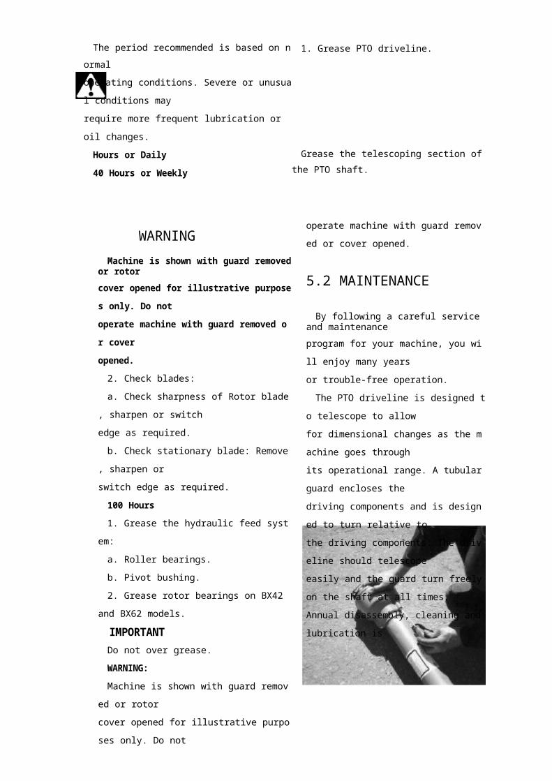
The PTO driveline is designed to telescope to
allow
for dimensional changes as the machine goes through
its operational range. A tubular guard encloses the
driving components and is designed to turn relative
to
the driving components. The driveline should
telescope
easily and the guard turn freely on the shaft at all
times.
Annual disassembly, cleaning and lubrication is

recommended to insure that all components function as
intended.
To maintain the driveline, follow this procedure:
1. Remove the driveline from the machine.
2. Pull driveline apart.
3. Use a screwdriver to turn lock studs on each end.
There are 2 studs per guard.
4. Pull the shaft out of the plastic tubular guard.
5. Use a solvent to clean the male and female
portions of the telescoping ends.
6. Apply a light coat of grease to each end.
7. Use a solvent to wash the grooves on each end
where the studs are located. Clean each end also.
8. Apply a light coat of grease to each groove.
9. Insert the shaft into its respective guard and align
the studs with the holes.
10. Insert the studs through the holes and seat in the
groove.
11. Turn each stud to secure guard to shaft.
12. Check that each guard turns freely on the shaft.
13. Assemble the driveline.
14. Check that the driveline telescopes easily.
15. Replace any components that are damaged or
worn.
16. Install the driveline on the machine.
Guard Removal
6 SPECIFICATIONS
6. 1 MECHANICAL
DisassembledDRIVELINE COMPONENTS
SPECIFICATIONS SUBJECT TO
MODEL BXH-5x10 BXH-7x12
Rotor blades 4pcs 4pcs
Rotor size 25" 28"
rotor weight 125lbs 185lbs
chipper capacity 5 inch 7 inch

hydraulic flow 3-6gpm 3-6gpm
chipper housing opening 5"X10" 7"x12"
discharge hood rotation 270 degree 270degree
pto rpm 540rpm 540rpm
tractor power 18-50hp 40-100hp
weight 845lbs 1300lbs
6.2 BOLT TORQUECHECKING BOLT TORQUE
The tables shown below give correct
torque values
for various bolts and cap screws. Tighten
all bolts to
the torques specified in chart unless
otherwise noted.
Check tightness of bolts periodically,
using bolt torque
chart as a guide. Replace hardware with
the same
strength bolt.
BoltDiameter
"A"
Bolt Torque*
8.8
(N.m) (lb-ft)
10.9
(N.m) (lb-ft)
M3M4M5M6M8
M10M12M14M16M20M24M30M36
.5 .43 2.26 4
10 725 1850 3790 66
140 103225 166435 321750 553
1495 11032600 1917
1.8 1.34.5 3.39 7
15 1135 2670 52
125 92200 148310 229610 450
1050 7742100 15503675 2710
TubeSizeOD(in.)
Nut SizeAcrossFlats(in.)
TorqueValue
(N.m)(lb-ft)
RecommendedTurns To Tighten
(After FingerTightening)
(Flats) (Turn)
3/161/4
5/163/1/25/83/47/8
7/169/165/8/ 6
7/81
1-1/41-3/8
8 612 916 122446 3462 46
102 75122 90
1 1/61 1/61 1/6
/61 1/61 1/6
3/4 1/83/4 1/8
BoltDiameter
"A"
Bolt Torque*
SAE 2
(N.m) (lb-ft)
SAE
(N.m) (lb-ft)
SAE
(N.m) (lb-ft)
1/4"5/16"3/8"
7/16"1/2"
9/16"5/8"3/4"7/8"1"
8 613 1027 2041 3061 4595 60
128 95225 165230 170345 225
12 925 1945 3372 53110 80155 115215 160390 290570 420
850 630
17 1236 2763 45
100 75155 115220 165305 220540 400880 650
1320 970
ENGLISH TORQUE SPECIFICATIONS
METRIC TORQUE SPECIFICATIONS
Torque figures indicated above are valid for
non-greased or non-oiled threads and heads unless
otherwise specified. Therefore, do not grease or oil
bolts or cap screws unless otherwise specified in this
manual. When using locking elements, increase torque
values by 5%.
* Torque value for bolts and cap screws are
identified by their head markings.
6.3 HYDRAULIC FITTING
TORQUE
Tightening Flare Type Tube Fittings *
1. Check flare and flare seat for defects that might
cause leakage.
2. Align tube with fitting before tightening.
3. Lubricate connection and hand tighten swivel nut
until snug.
4. To prevent twisting the tube(s), use two wrenches.
Place one wrench on the connector body and with the
second tightens the swivel nut to the torque shown.
5. The torque values shown are based on lubricated
connections as in rears.