· web viewsection 01 asphalt paving section 02 precast concrete paving section 03 curbs, drains,...
TRANSCRIPT
Iraq's national housing and new urban development2. Infrastructure engineering specificationsPhase 1: 25,000 units in the apartmentAL BASRA New Town Project
table of Contents1. Outline of the construction project of housing units2. Infrastructure engineering specifications3. Basic drawings of housing unit construction projects4. Infrastructure drawings5. House Building Engineering Bill of Materials (BOM)6. Infrastructure Engineering Bill of Materials (BOM)
Outline specificationPart 1 General requirementsSummary of the first paragraphSection 02 ReferenceSection 03 Quality ControlPart 2 EarthworkSection 01 EarthworksSection 02: Joint work of earthworkSection 03 Excavation and FillingSection 04 concrete pilePart 3 Concrete EngineeringSection 01 OverviewSection 02 ReferenceSection 03 Concrete Engineering MaterialsPart 4 Frame EngineeringSection 01 OverviewSection 02 ReferenceSection 03 Template EngineeringPart 5 pipe

Section 01 OverviewSection 02 ReferenceSection 03 Material InspectionSection 04 Pipeline Pressure TestPart 6 pavingSection 01 Asphalt PavingSection 02 Precast Concrete PavingSection 03 curbs, drains, sidewalks and drivewaysSection 07 UtilitiesSection 01 water distribution pipeSection 02 sanitary appliances sewage pipelineSection 03 Storm Practical Drainage PipelineSection 04 Telecommunications UtilitiesSection 05 Electrical UtilitiesSection 06 LandscapingSection 07 Gas SupplySection 08 Incinerator FacilitiesSection 09 Landfill Facilities
Part 1: General requirements01 work summaryThe work under this contract includes all the labor, tools, materials, equipment, organization and supervision required for the full construction of 25,000 affordable infrastructure in Basra, Istanbul. This work includes all on-site work (water, sewage, etc.) related to infrastructure construction, excavation, backfilling, paving and utilities (water treatment plants, sewage treatment plants). Work on the infrastructure should include all concrete, piping, communications, gas supply, and electrical engineering is also included in this contract. Specifications for water treatment plants and wastewater treatment plants will be developed through the application of US, UK and other international standards at the

detailed design stage.02 ReferencesA. The Al Basra New Town development project is designed to comply with local or internationally recognized regulations and regulatory requirements.1. ASTM A185 steel welded wire standard specification, common, for concrete2. ASTM A615M Standard Specification for Deformation and Ordinary Carbon Reinforcement for Concrete Reinforcement3. ASTM C31 Standard Practice for Fabricating and Curing Concrete Specimens on Site4. ASTM C94 Ready-mixed Concrete Standard SpecificationAmerican Society for Testing and Materials C131 standard test method for resistance to degradation of small coarse aggregates1. Loss and impact of Los Angeles machines6. ASTM C143 Standard Test Method for Slump of Hydraulic Concrete7. ASTM C150 Portland Cement Standard Specification8. ASTM C260 Aerated Concrete Admixture Standard Specification9. ASTM D692 Standard Specification for Asphalt Pavement Mixtures10. ASTM D806 Hardened Soil - Standard Test Method for Cement Content in Cement Mixtures11. ASTM D977 Emulsified Asphalt Standard Specification12. ASTM D1073 Asphalt Pavement Mix Fines Standard Specification13. ASTM D1139 Standard Specification for Aggregates for Single or Multiple Asphalt Surface Treatments14. ASTM D1241 Standard Specification for Soil Aggregate Subbase, Base and Surface Layer Materials15. ASTM D1557 uses laboratory compaction with improved work (56,000 ftlb / ft3 (2700 kNm / m3))16. Standard Test Method for Compressive Strength of ASTM D1633 Molded Soil Cement Cylinder
17. ASTM D2487 Engineering Soil Classification (Unified Soil Classification System)18. ASTM D2940 Expressway or Airport Base or Subgrade Grade AggregateB. Alternative codes and standards or modifications to the requirements are available and require prior agreement between the NIC and Al Rajhi-TRAC Middle East.03 quality controlA. Quality control includes:1. Contractor's construction quality plan2. Contractor's quality control representative3. Engineer's monitoring4. Engineer's inspection and testing5. Contractor's quality control test6. Test report7. Quality Control Audit8. Compliance Certificate
Part 2: Earthwork01 Earthwork1.1. OverviewA. Earthwork includes the following:1. Site preparation and excavation2. Excavation, backfilling and compaction of foundations, mechanical and electrical work for all utilities.2.1. materialA. Filling and backfilling1. The material shall consist of excavated soil or approved borrowing and shall not have vegetation, debris, clods or stones larger than 3" (76 mm) in maximum size.02 Earth's ordinary work results 1.1. generalA. Earthwork includes the following:
1. Building mats and foundations2. Residential block2.1. Atlantic, sign and warning deviceA. Traffic barriers, traffic signs and warning equipment should meet the requirements of applicable standards03 Digging and filling 1.1. generalA. This section includes the following:1. Excavation and filling: foundation and structure; on-site drainage, structure and function.2. Embankment3. Controlled filling using materials from imported and on-site sources.4. Soil and aggregate5. Compaction and testing2.1. FillerA. Applicable materials: Materials from site excavation and permitted off-site sources that meet all of the specific requirements for their intended use and are not suitable. Wet road base materials that meet other suitable material requirements are suitableB. Unsuitable materials: Materials that do not meet the requirements of the appropriate materials; or include any of the following:1. organoclay, organic sludge or peat; as defined in the applicable standard2. Vegetation, wood, roots, leaves and organic degradable materials.3. Any size of stone or gravel over 6 inches4. Porous biodegradable materials, excavation pavement, construction waste, garbage or garbage5. Ice, snow, frost or frozen soil particles.C. General fillers: suitable, unclassified substancesD. Structural Fillers: Suitable materials classified by the Unified Soil Classification System (USCS) according to applicable standards. It is
confirmed that the size of the largest particles in the filler is not more than half the thickness of the compacted lift.E. Embankment packing: structural packing; classified according to applicable standardsF. Concrete filler: 03 30 00G. Granular fillerH. Sand: Granular material free of clay balls, organic matter and other harmful substances. The minimum sand equivalent of each applicable standard is 30, which meets the following ratings:
Screening Name (square grid) Percentage by weight
3/8-in 100
No.4 75 to 100
No.30 12 to 50
No.100 5 to 20
No.200 0 to 10
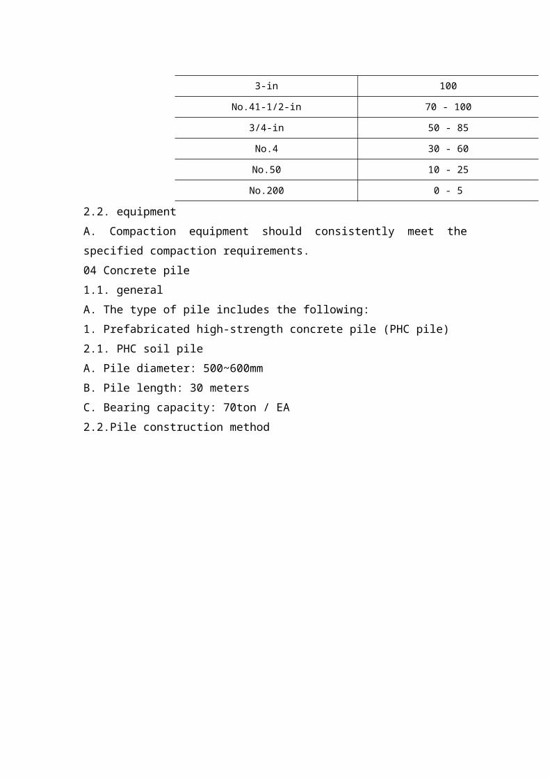
I. Choose to borrow:1. Well graded, coarse grained soil; classified according to applicable standards2. Soil particles: physical properties requirements3. Gradient: the following table
Screening Name (square grid) Percentage by weight
3-in 100
No.41-1/2-in 70 - 100
3/4-in 50 - 85
No.4 30 - 60
No.50 10 - 25
No.200 0 - 5
2.2. equipmentA. Compaction equipment should consistently meet the specified compaction requirements.
04 Concrete pile1.1. generalA. The type of pile includes the following:1. Prefabricated high-strength concrete pile (PHC pile)2.1. PHC soil pileA. Pile diameter: 500~600mmB. Pile length: 30 metersC. Bearing capacity: 70ton / EA2.2.Pile construction method
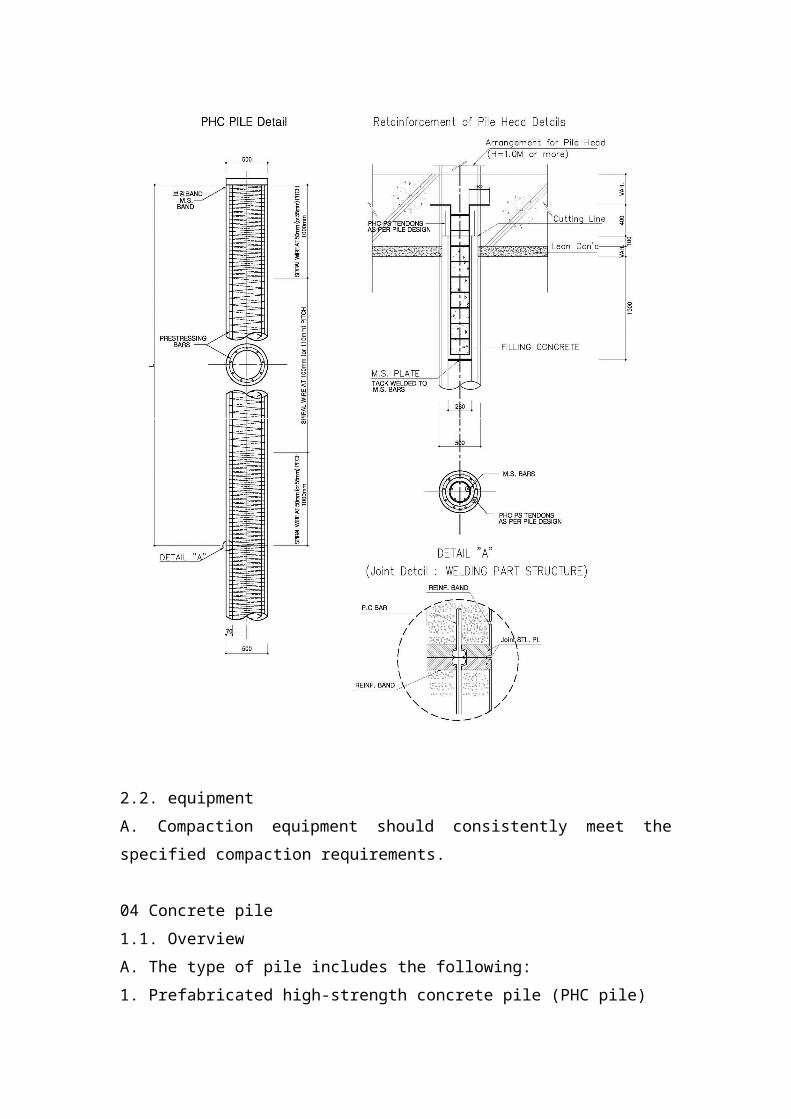
2.2. equipmentA. Compaction equipment should consistently meet the specified compaction requirements.
04 Concrete pile1.1. OverviewA. The type of pile includes the following:1. Prefabricated high-strength concrete pile (PHC pile)2.1. PHC pileA. Pile diameter: 500~600mmB. Pile length: 30 metersC. Bearing capacity: 70ton / EA2.2. Pile construction method
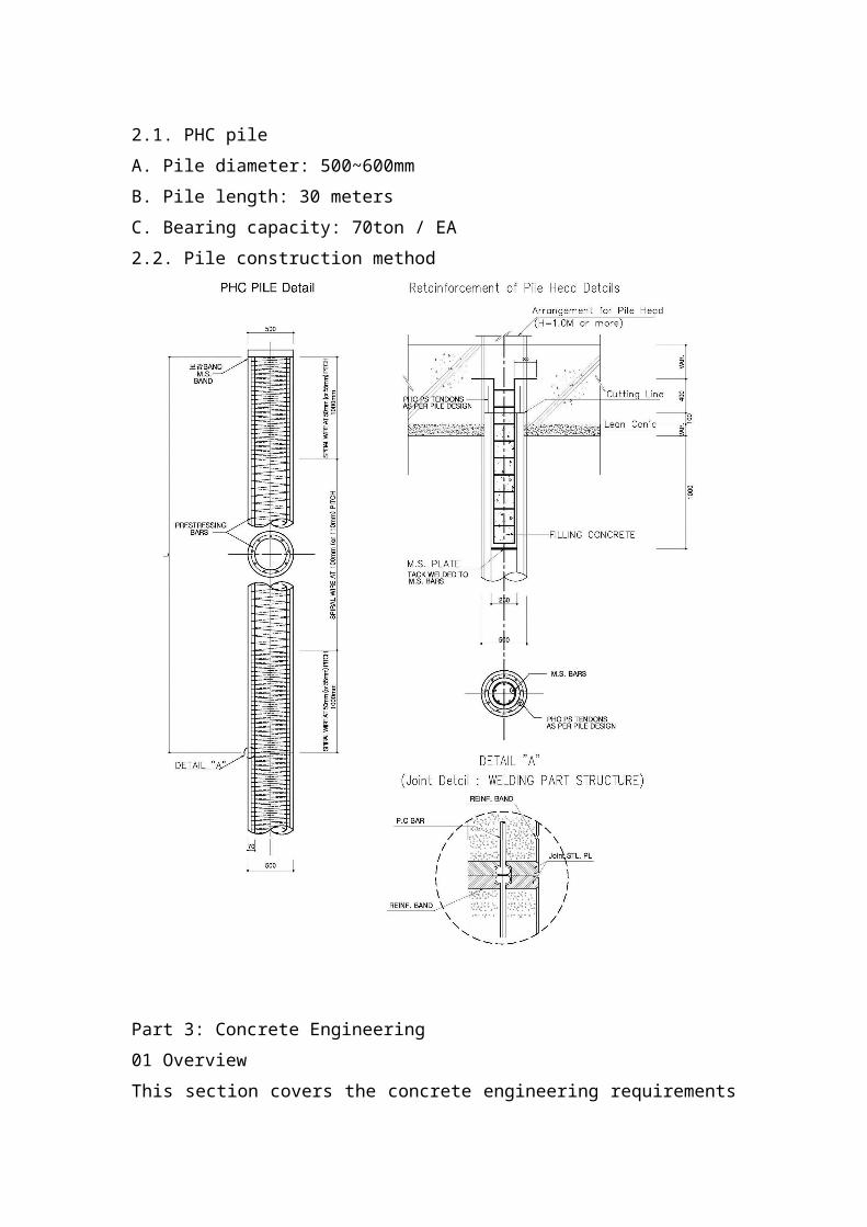
Part 3: Concrete Engineering01 OverviewThis section covers the concrete engineering requirements for piping, road works, runways, structures, water retaining structures, foundations and structures and equipment foundations.02 ReferencesApplicable to the specifications, design standards, standard drawings and unit standards set by the Korean and Iraqi
governments. The design work was carried out in order to comply with international standards and regulations.ACI 211 recommended method for selecting the proportion of structural concreteRecommended Practice for ACI 214 to Assess Compressed Test ResultsOn-site concreteHot weather concrete construction procedure recommended by ACI 305ACI 315 "Standard Implementation Manual for Reinforced Concrete Structure Details"Specification for BS 12 normal and fast hardening Portland cementBS 812 mineral aggregate, sand and filter sampling and test methodsBS 882 natural source aggregatesBS 1305 batch concrete mixerBS 1370 Low Heat Portland Cement SpecificationBS 3148 concrete water test methodBS 3963 concrete mixer mixing performance test methodSpecification for BS 4027 sulfate-resistant Portland cementBS 4483 steel fiber for reinforcing concreteBS 4550 cement test methodBS 5075 concrete admixtureBS 5328 concrete designation method (including ready mixed concrete)BS 8004 FoundationBS 8007 water retention structureBS 8110 concrete structure useBS 8210 frame type building structure03 concrete engineering materialsA. Aggregate: Durable aggregate that meets the requirements. The aggregate used in the concrete should be the same as the
aggregate used to prepare the mixed proportion sample for the compressive strength test and have the same classification. B. Cement: Portland cement that meets the requirements.C. Water: Drinking water.D. Additives: Admixtures should be free of chloride ions unless otherwise approved. The concrete used in the concrete should be the same as the mixture used in the approved mixing ratio sample. E. Gasification additives: Gasification additives should meet the requirements.F. Fly ash: Fly ash and raw or calcined natural volcanic ash should meet the requirements.G. Plasticizer: Plasticizer should meet the requirementsH. Water reduction, acceleration and mixing admixtures: water reduction, acceleration and mixing admixtures should meet the requirementsType A - Water ReductionType B - AccelerationType C - Water reduction and decelerationType E - Water reduction and accelerationF type - high water reduction rangeType G - High water reduction, slowdownI. Adhesive: An acrylic latex emulsion adhesive suitable for bonding new concrete to existing concrete or new concrete. J. Mortar: Cement mortar.K. Finishing plaster/gypsum: cement-based, aggregate-type finishing slurry. The finished color should be gray.L. Curing compound: A liquid film-forming compound composed of a wax, a resin or other material. The curing agent should meet the requirements. The curing agent should meet all other recommended concrete surface treatments.M. Plastic film moisture barrier: requirements for polyethylene film with minimum thickness.
Part 4: Template01 generalThe contractor shall determine the route, route and height of the various roads and structures and establish baselines and profiles to indicate the route and level of construction. All benchmark marks and profiles should be effectively protected before the permanent project is completed. The formwork and scaffolding shall be constructed to withstand the loads imposed by the fresh concrete and the additional stresses imposed by the vibration equipment and construction traffic so that the concrete surface should be in the drawing after the concrete has hardened.Materials selected for formwork and scaffolding should consider strength, stiffness, durability, workability, impact on new concrete, and economy02 ReferencesBS 1088 templateBS 5975 Scaffolding Code of Practice03 templateA. Ground support should be properly designed on the foundation to prevent settlement. Ground support should be properly designed on foundations that prevent settling.B. Unless otherwise stated, the seams of the exposed face formwork shall be evenly spaced, horizontal or vertical and shall be continuous or form a regular pattern. All seams of the formwork, including the formwork of the construction joints, should be tightly protected against the shedding of cement and fines.Where reinforcement is through the formwork, the formwork should be placed against the strip.C. Before any steel bars are placed in the mold, the latter should be thoroughly cleaned and then sanded with a release agent.D. All wedges and other adjustments should be prevented from moving during concrete placement before concrete placement
begins, and the contractor should maintain the formwork watch during the casting process to ensure that no movement occurs.E. Carefully remove the template without impact or interference with the concrete. The formwork shall not be removed unless the concrete has sufficient strength to withstand any stresses that may be experienced thereby.F. Once the formwork is removed, the bolt holes on the concrete surface other than the construction joints (not required for future operations) should be completely filled with dry, non-shrinking mortar to prevent surface collapse.Part 5: Pipes01 generalAll piping, fittings, brackets, valves and fittings shall be provided by the Contractor. In addition, the Contractor shall provide all labor, materials, equipment and debris required to install piping, fittings and accessories. The pipe reference should be applied to the DIN standard or equivalent standard during the design development phase.02 ReferencesBS EN 752-4:2008, Drainage and drainage systems outside buildingsBS EN 14161:2003, Pipeline transport systemsBS 410-2: 2000, test sieve. Technical requirements and testing.BS EN 12620:2002, aggregates of natural sources of concreteBS 1924, Stabilizing materials for civil engineeringBS 6031, Code of Practice for EarthworksBS EN ISO 12958:1999, method for testing geotextilesBS EN 1452:2000, fittings and fittings for unplasticized PVC pressure pipesBS EN 13598-1:2003, unplasticized polyvinyl chloride (PVC-U) pipes and plastic fittings03 Material InspectionThe contractor/manufacturer shall submit an inspection test plan
approved by the engineer prior to the commencement of the project or prior to the production of the plant. Engineers should participate in manufacturing and construction activities at all stages to ensure quality control at each stage. Engineers should designate an experienced, well-known third party for quality control at the production plant or site. Complete catalogues and specifications should be provided prior to delivery.Pipes should be rejected due to non-compliance with the following:A. Failure to pass the hydraulic testB. The longitudinal concrete surface of the joint failed to meet the dimensional toleranceC. Fracture or crackD. Defects indicating poor mixingE. Surface defects indicating honeycomb or open textureF. Insufficient coverage of steel bars.04 pipeline pressure testThe pipeline should be tested. The test should be carried out as follows:A. Pipes should be filled with water and all air as much as possible.B. The pressure is then increased by pumping in water until the test pressure is reached and maintained at this level by further pumping until it is stable.C. Then stop pumping and record the time it takes for the observed pressure to drop by 1.5 meters.D. The test pressure is 1.5 X working pressure.E. Then restart the pumping and record the amount of water pumped to restore the test pressure. If the test pressure does not drop by 1.5 meters after three hours, the pumping should be restarted at this stage, and the time is recorded as three hours.F. The loss rate is then calculated by dividing the number of records by the time of the record. The test pump and pressure gauge should be connected to a position other than the highest point of the pipe

to facilitate the release of air from the highest point.G. If the pipeline fails the test, locate and repair the fault and retest the pipeline until it passes the stress test. All exposed pipes, fittings, valves and fittings should be visually inspected during the test.
Part 6: Paving01 Asphalt paving1.1. generalA. This work should include the construction of the composition, the mixing, the prepared roadbed, and the protection of the hot asphalt concrete pavement.2.1. productA. Basic course materials1. Class 2 aggregate foundation mineral aggregateB. Prime Minister and sticky coat1. Bottom coating: liquid asphalt, slow curing type.2. Adhesive coating: diluted emulsionC. Asphalt paving materials1. Paving asphalt: steam refined AR-4000 grade2. Aggregate: Type A, the combined aggregate is graded to 1/2 inch maximum size, medium grade or 3/4 inch maximum size, medium grade, as shown.3. Mixed facilities: Asphalt concrete surfacing materials shall be provided by an approved commercial asphalt central mixing equipment.D. Sealing jacket1. As shown, the fog seal coating or seal coatingF. Hybrid design1. The design of asphalt concrete mix shall be provided by the Contractor and shall be obtained from a qualified independent testing laboratory or institution and shall have an appropriate

design of the asphalt concrete mix. The jacket that is designed for the mix should be at the expense of the contractor.2. The design of asphalt concrete mix, including aggregate quality and grading, should meet quality requirements.02 precast concrete paver 1.1. generalA. This section includes the following:1. Concrete slab and asphalt set bed.2.1. Concrete unit paving (interlocking block)A. The paver shall be an interlocking precast concrete unit manufactured by Type I Portland cement ASTM-C150, the aggregate of which conforms to ASTM C33. Equipment that does not damage or in any way damage its appearance (as landscape architects think). The paver should meet the following requirements:1. Paver style: marked in the plan2. Paving the airport: specify in the plan3. Double Soldier Accent Border CourseOne. Color: specify on the planBay mode: pointed out in the planC. Paver Size: Medium Rectangle - 6''x 8''4. The model mentioned in the plan03 curbstone, gutter, sidewalk driveway 1.1. OverviewA. This section includes:1. Portland cement concrete pavement, cement walkway, curb and drain, garbage collection area, ramp, fence column foot, sliding door concrete track, collecting basin, pipe bedding and sheath, thrust block, transition structure , flagpoles and light standard bases and foundations, sports equipment foundations and equipment mats.2.1. materialA. Form: The size and strength of steel, wood or other suitable material to prevent movement during concrete placement and to maintain horizontal and vertical alignment until removal. Use

straight lines to avoid distortion and defects.1. Use a non-colored release agent that does not stain or damage the concrete surface to form a coating2. Rebar should be placed and supported as shown to provide at least 2" (50mm) concrete cover.B. Rebar: Deformed steel, please refer to applicable standardsC. Connecting pin steel bars: ordinary steel bars, the cutting bars are square in length, square at ends and free of burrs.D. Anti-flaking compound: 50% by volume of boiled linseed oil and 50% by volume of mineral oil.E. Epoxy Adhesive: Two component materials suitable for dry or wet surfaces, in accordance with applicable standards. Provide the type, grade and grade of material that meets the project requirements.2.2. Concrete mixing, design and testingA. Design the mixture to produce standard weight concrete consisting of Type II Portland cement, aggregate, water reducer or high range water reducer (superplasticizer), aerated mixture and water to produce the following minimum performance .B. Compression strength: 2,500 psi, (176 kg / cm2) at 28 days unless otherwise stated.1. Slump range: 8" (200mm) for concrete containing HRWR (high concentration water reducer) mixture (superplasticizer); 3" (75mm) for other concrete.2. Air content: 5% to 8%.2.3. Curing and sealing materialsA. Transparent, water-based, film-forming curing and sealing compounds: specially made for colored concrete with reference to applicable standards.
Part 7: Utilities1.1. Overview
A. This section specifies the following underground utilities. The contractor or owner’s representative must check the utility before digging or backfilling1. New utilities2. Existing utilitiesB. The contractor must coordinate all utility interruptions and coordination with local authorities. The appropriate utility officer must be notified at least 48 hours prior to the disruption of the utility, otherwise the utility may be disrupted.C. In the case of removal of contaminants (excavation or excavation), the person responsible for the work must coordinate with the project manager or local authority in accordance with applicable rules and regulations.D. During the construction period, the contractor will be responsible for all the facilities consumed. Where applicable, the contractor will arrange for the project developer to not provide utility services with the local utility distributor. In the event that measuring these utilities is not feasible, the project developer may approve another form of utility payment.01 Hydropower station water distribution pipeline:1.1. OverviewA. This section specifies materials and procedures for the distribution of groundwater outside the building, fire water and irrigation systems that have been completed and are ready. This includes pipes, structures, accessories and all other miscellaneous items.2.1. Ductile iron pipe and fittingsA. Directly buried ductile iron pipe:1. Provide ductile iron pipe that meets the requirements of applicable standards, with a pressure rating of 350 psi, suitable for pipes with diameters of 100mm to 300mm and 250psi, standard thickness cement mortar lining, internal asphalt seal and external
asphalt coating.2. The following grades: Pipes that do not exceed the nominal 6m length by rubber ring joints, mechanical joints or approved restrictive joints. Flange connections are provided where indicated on the drawing. Provide each joint with a sufficient number of attachments to provide mechanical and constrained joint piping.B. All fittings: Ductile iron with a minimum rated pressure of 2400 kPa (350 psi). Accessories must meet the requirements of applicable standard specifications. Rubber gasket joints shall comply with applicable standards for mechanical and push-in fittings. Ball joints shall comply with applicable standards and shall be fitted with a separately cast ductile iron cover that complies with applicable standards. Flange fittings shall comply with applicable standards and, in accordance with applicable standards, use full gaskets, flat and drilled to 850 kPa (125 psi) or 1725 kPa (250 psi) stencils according to applicable standards.C. Provide cement mortar lining and asphalt seal coating on the inside of pipes and fittings according to applicable standards. A standard asphalt coating is provided on the outside.D. Provide a factory hydrostatic test of not less than 3.5 MPa (500 psi) for all pipes in accordance with applicable standards.E. Provide undetectable adhesive-supported marking strips on the top and sides of all embedded ductile iron pipes, extending the extension joints to the joints along the length of the pipe, and marking the black lettering at intervals not exceeding 300 mm Pipeline service. , the color of the tape background should be as follows: water blue3.1 Hydraulic estimation of the water distribution networkA. Use the 'Hazen-Williams Formula' to calculate estimates for water and raw water pipelines by the 'Hardy-Cross' method. (emission estimation formula)B. Plan uniform water supply and maintain minimum dynamic water
pressure at the end of the pipe.C. The final distribution network is based on repetitive computing activities, planning the network in the most economical and mathematical way. D. Overview of the Hardy Cross Method.1. After confirming the first expected emissions for each pipeline, the calculated corrected emissions can be determined based on the double counting activity.2. The calculation process is in line with the theory, rapid repeat calculation, head loss, hydraulic gradient and flow calculation are accurate to 3 to 5 decimal places.E. Hasen - Williams FormulaV = 0.35464 × C × D 0.63 × I0.54Q = 0.27853 xCxD2.63x I0.54 from I: hydraulic gradient (%)C: speed coefficient D = 1.6258 × C - 0.38 × Q0.38 × I - 0.205 where V: speed (m / s)D: pipe diameter (mm)I = 10.666 × C - 1.85 × D - 4.81 × Q1.85 Q: Discharge (m3 / sec)F. Velocity Coefficient: Although the C value in the Hasen-Williams formula varies with curve and roughness, if the loss caused by friction and curve is considered, it can be calculated according to the following formula.
Pipe Type C
value
Remark
Ferroconcrete Pipe 130
Safety range of C value :
110~120 C
P.S Concrete Pipe P.S 130
Unplasticied Poly-Vinyl Chloride
Pipe
110
Cast Iron Pipe 110 20 years after construction
Coated steel pipe 110
02 Health Utilities Sewage Pipeline:1.1. generalA. This section specifies the materials and procedures for the construction of underground sewers for sanitary facilities outside the building, which are completed and ready. This includes pipes, manholes, pumping stations, ventilation, sewage squirts, structures, cleaning, accessories and all other miscellaneous items.2.1. Sanitary down pipes and fittingsA. PVC flexible joint plastic pipe: refer to applicable standards, polyvinyl chloride (PVC) material; bell and socket type rubber gasket joints.1. Pipe category: SDR 352. Connector: PVC meets pipe specifications3. Connector: Refer to the applicable standard, elastic washer.B. Ductile iron gravity sewer: Refer to applicable standards, Bell and port. Appropriate standards and complete catalogues and specifications should be provided prior to supply.1. Pipeline category: 8" to 12" pressure rating 350 psi, 14" and greater pressure rating 250 psi.2. Accessories: ductile iron, compact accessories3. Connector: Rubber gasket that meets applicable standards.2.2. Underground pipeline markingA. Plastic ribbon belt: The bright green color is continuously printed with a capital letter “sanitary sewer” with a minimum width of 6 inches and a thickness of 4 mils.2.3. HoleA. Concrete manhole: as indicated in 33 05 14 and marked on the drawing; engraved with the cover of “SANITARY SEWER”.2.1. Sewage calculationA: This project is a new urban development project in Iraq. The estimated percentage of people accepted is 100%.B. Sewage units are estimated to be derived from per capita daily

demand and sewer conversion (0.9 from water consumption).C. Hydraulic estimation of pipelines and pumping stations1. The sewer plan should plan the maximum sewage flow by hour.2. Smallest sewage flow rate = daily average sewage flow × 2.0 (peak factor)
25,000 affordable infrastructure for the first phaseAl Basra New City Project
03 storm water pipeline1.1. OverviewA. This section includes the construction, modification and/or installation of drains, drain manholes, collection basins, launching inlets, storm drain structures, junction boxes and accessories as required by the contract documents.
2.1. Pipe size and materialA. The minimum size of the drain pipe should be 15 inches (15"). The pipe within the public access authority should be GRP. Corrugated metal and plastic pipes can be used for public access.
2.2. specificA. Slight concrete: Meets applicable standards, unless otherwise specified on the drawings.Type II modified Portland cement shall comply with applicable standards.
2.3. Cement mortarA. Cement mortar consisting of 1 part Portland cement and 2 parts by volume of sand shall comply with applicable standards.
2.4. Precast concrete wood panel
A. Prefabricated tuyere drainage manholes shall comply with applicable standards. The pre-made manhole portion of the rainwater drainage is connected by a sealant. All manhole bases are placed on site unless explicitly stated in the contract documents and drawings or as directed by local government engineers.
2.5. Manhole frame and coverA. The manhole frame and cover shall be of pre-cast material or approved equivalent material and covered with a “storm drain”.
2.6. Strengthen the barA. Rebar shall comply with ASTM A615, SS Section 52-1.02 “Materials” and ACI 318 Class 60.
2.7. Collection basin frame and rain raftA. The frame and grille of the collection basin shall be made of structural steel. The cover shall be made of galvanized cast iron conforming to ASTM A36 and cast iron conforming to SS Section 75-1.02B “Frame, Grille and Cover”.
2.8. Precast concrete manholeA: For alternative construction, the contractor can use a prefabricated drain box.
2.9. Backfill materialA. Unless otherwise specified, the requirements for trench backfill materials and backfill materials shall be in accordance with applicable standards.B. The initial backfill material in the ground area saturated with water shall be granular material, clean and free of clay, silt or organic matter, and shall be Class 1 and Class B, meeting the
requirements of applicable standards.C. Backfilling should be carried out in layers, 20 cm per layer, and each layer should be compacted by 95%.2.10. Rainwater calculationA. Rainwater flow1. Calculate the rainwater flow design by a reasonable formula.Q = 1/360 C I AQ: Choose the runoff rateC: dimensionless runoff coefficient for adjusting rainfall abstractionI: Rainfall intensity duration is equal to basin concentration time A: basin areaB. Rainfall intensity (I)1. The design rainfall intensity is calculated according to the formula (received by the Basra government).I = 700 /(t + 25)Rainfall intensity (mm/h) ton: duration
04 Telecom Utilities1.1. OverviewA. Work Summary: Design and Construction of Telecommunications Equipment(such as routers, switches, etc.) in the first phase of Basra New City2.1. IP / access networkA. L3 S / W: The Layer 3 switch is a router that performs fast forwarding through hardware. IP forwarding typically involves route lookup, decrement time to live (TTL) counts, and recalculation of checksums, and forwards frames with the appropriate MAC headers to the correct output port. The lookup can be done in hardware, and the TTL decrement and checksum recalculation can also be done. Routers run routing protocols such as Open Shortest Path First (OSPF) or Routing Information Protocol (RIP) to communicate with other Layer 3 switches or routers and build their routing tables. Look

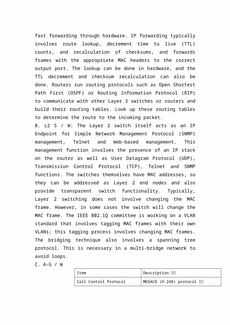
up these routing tables to determine the route to the incoming packet.B. L2 S / W: The Layer 2 switch itself acts as an IP Endpoint for Simple Network Management Protocol (SNMP) management, Telnet and Web-based management. This management function involves the presence of an IP stack on the router as well as User Datagram Protocol (UDP), Transmission Control Protocol (TCP), Telnet and SNMP functions. The switches themselves have MAC addresses, so they can be addressed as Layer 2 end nodes and also provide transparent switch functionality. Typically, Layer 2 switching does not involve changing the MAC frame. However, in some cases the switch will change the MAC frame. The IEEE 802.1Q committee is working on a VLAN standard that involves tagging MAC frames with their own VLANs; this tagging process involves changing MAC frames. The bridging technique also involves a spanning tree protocol. This is necessary in a multi-bridge network to avoid loops.C. A-G / W
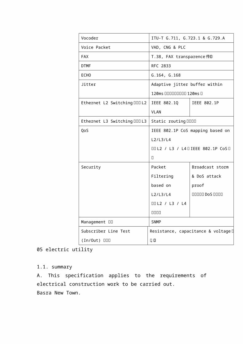
Item Description 描述Call Control Protocol MEGACO (H.248) protocol 协议Vocoder ITU-T G.711, G.723.1 & G.729.A
Voice Packet VAD, CNG & PLC
FAX T.38, FAX transparence传真透明DTMF RFC 2833
ECHO G.164, G.168
Jitter Adaptive jitter buffer within 120ms自适应抖动缓冲区在 120ms内
Ethernet L2 Switching以太网 L2 IEEE 802.1Q
VLAN
IEEE 802.1P
Ethernet L3 Switching以太网 L3 Static routing静态路由QoS IEEE 802.1P CoS mapping based on
L2/L3/L4
基于 L2 / L3 / L4的 IEEE 802.1P CoS映射Security Packet Filtering
based on
L2/L3/L4
基于 L2 / L3 / L4
的包过滤
Broadcast storm &
DoS attack proof
广播风暴和DoS攻击证明
Management 管理 SNMP
Subscriber Line Test (In/Out) 用户线
Resistance, capacitance & voltage电阻,电容
05 electric utility
1.1. summaryA. This specification applies to the requirements of electrical construction work to be carried out.Basra New Town.
1.2. The scope of workA. Basra New Town project consists of electrical systems, as shown in the figure, the electrical system is composed as followsTransmission line2. 132 / 33kV substation3. Distribution line4. 33 / 11kV substation5. Street lighting and traffic signals
1.3. Code and standardsA. Equipment shall be manufactured in accordance with the latest edition or version of the applicable regulations and standards below. Electrical equipment should meet standardsMOE or equivalent standards are in the design development phase.
1. Korean Industrial Standard (KS)2. Japanese Standards and Specifications (JIS, JEC, JEM)3. American Electrical Manufacturers Association (NEMA)4. Institute of Electrical and Electronics Engineers (IEEE)5. American National Standards Institute (ANSI)6. National Electrical Code (NFPA No. 70)7. International Electrotechnical Commission (IEC) 8. British Standard (BS)
1.4. Transmission lineA. The transmission line type is an overhead line type.B. Overall distance - about 5.5 kmC. The transmission line will be carried by the rigid tower.D. According to the site situation, the variable rigid tower type will be applied.Straight tower2. Corner Tower3. Strain tower4. Anchor tower. and many more
1.5. 132 / 33kV substationA: The 132/33kV substation should be designed with dual busbar GIS.
B. The circuit beaker should be of the SF6 gas type for 132kV and 33kV.C. Electrical equipment installed indoors should be cabinet type including electrical equipmentD. The controller should be based on the local conditions of the circuit breaker and the remote arrangement of the control system or operator.
E. The main equipment specifications are as follows:1. Substation capacity: 40 / 45MVA x 4Units (180MVA)2. Control equipment: power SCADA (monitoring and data acquisition)3. Insulation type: SF6 gas insulation (132kV and 33kV)1.6. Distribution wiringA. Cycling of the entire site to improve the safety and reliability of the power supply facility.B. In the case of a line fault, the relays on either side of any faulty part act through the relay.C. Stable line uninterruptible power supply is available.D. Install the underground cable duct using a conduit that is resistant to vehicle loads and insert the cable into the conduit.E. The distribution voltage is planned to be 33kv, 3-phase 3-wire system and 50Hz.F. The Basra New Town project consists of an electrical system, as shown in the figure, the electrical system consists of the followingPower system2. Cable work3. Grounding1.7. 33kV / 11kV substationA: 33kV substation should adopt double busbar GIS designB The 11kV circuit breaker of each transformer shall be interlocked with its associated 33kV circuit breaker to:1. 33kV circuit breaker cannot be closed unless the 33kV circuit breaker is closed2. If the 33kV breaker is open, the 33kV breaker trips. C. The following systems will be designed, but are not included in the scope of work:1. High voltage switchgearOne. Circuit breaker: vacuum circuit breaker (VCB) (MCCB), etc.2. Panel
One. Main switchboard (MDB), switchboard (DB), power supply and lighting switchboards should be equipped with circuit breakers, pre-dead structure, in accordance with IEC 60439.Bay circuit breakers shall be of the molded housing bolt type.1.7. Street lighting and traffic signals25,000 affordable infrastructure for the first phaseAl Basra New City ProjectA. Street lighting1. Power system and method of turning on/off the light- Load capacity: 1φ2W220V2. Lighting standards- Illuminated road lighting is determined by the shape of the road, the type of road, the speed of travel, the amount of traffic, and other states of the lighting fixture.3. Light source (light)- Ample lighting with external lighting.4. Lighting control1. Time and Sun S / W on / off2. Manually turn on/off with a local switch5. Wiring system1. The power cable will be used underground.The cable should be rated 0.6 / 1kV volts. Polyethylene for cable cover.B. Traffic signals1. Install traffic lights- Install signalling devices to improve traffic safety and smooth traffic flow2. Facility method- Traffic light type: incandescent light- Power facilities: installation of signal light control panel- Flood safety facilities in flood areas- the basis for installing control panel equipment
- Establish a service location above 1.5 meters3. Wiring system1. The power cable will be used underground.2. The cable should be a 0.6 / 1kV voltage rating consisting of polyethylene
06 landscapeA. Target1. Consider regional and spatial characteristics, circulation and land use plans2. Actively use existing natural resources and consider the status and condition of the entire site3. Maximize the function of the facility at the site and consider the surrounding beauty and ecological featuresB. Scope of workThe scope of the landscaping design is as follows but not limited to:Planting design- Select the course, purpose, method and type of planting, taking into account the vegetation conditions near the project site.- Coordinate with customers and choose trees with excellent operation and maintenance.2. Facility design- The landscaping facilities should be designed in accordance with Iraq's relevant laws and regulations, applicable to the facilities of the elderly, the infirm and the disabled, and should be durable, convenient and uniform, and determine the location, size, quantity and type to coordinate with the customer. Rear.2. Pavement design- Squares, walkways and sidewalk walkways should be considered in coordination with customers, taking into account geographical features, spatiality, functionality, aesthetics, landscape and natural
affinity.3. Irrigation and drainage design- Consider the conservation of trees in park green spaces, review the appropriate irrigation systems, introduce the required irrigation and drainage facilities, and design site drains and connections.4. Hydrophilic space design- When it is necessary to partition the pond and creek, alternative waterproofing and revetment methods should be provided after considering economics, structural stability and environmental friendliness after coordination with the customer.5. Park building design (toilet and administrative center)- Facilities, power and telecommunications plans should reflect the results of the discussions with relevant departments and site conditions and should be designed in coordination with the client.6. The indoor landscape design of other infrastructure and SOC facilities should be designed separately for each facility.
07 gas supply
A. Storage facilities1. Storage facilities: Concrete structures should be installed and buried underground.2. Vaporizer facilities: should be installed on the ground.3. Storage equipment materials: The equipment room materials are as follows: concrete for floor, non-flammable concrete brick wall and non-flammable roof slab.4. Gas equipment should adopt standards from the MOO standard during the design and development phase.

B. Pipeline1. Pipe material and markingOne. Polyethylene (PE) pipes (ISO 4437:2007 (KSM 3514)) for the supply of gaseous fuels should be used for pipes installed underground.Carbon steel pipes for ordinary pipes (ISO 65:1981 (KSD 3507)) should be used for pipes installed on the ground.C. Pipes installed on the ground should be painted yellow, and pipes installed underground should be marked as yellow.2. Pipe installationOne. Pipes should not be installed in these areas; internal building structures, basements and non-ventilated areas.Pipe installation within the Bay Building structure: N / AC. The pipe should not be installed in the pipe like a drain.d. Maintain proper burial depth between the exterior and the surface of the pipe after marking on the installation blueprintThat is, pipes installed on weak ground should be damaged by ground subsidence. Workers should prevent ground subsidence through gravel or pile work.F. Since the bedrock does not have a special condition for proper depth of the buried pipe, the worker should use a protective pipe or tube sheet with at least a considerable strength to protect the part from maintaining the buried depth. In this case, the depth between the exterior and the surface should be kept above 0.3 meters. The width of the fender is greater than or equal to 1.5 times the diameter of the pipe and 4 mm or the thickness of the stencil.G. Electrical anti-corrosion pipeline: Since polyethylene (PE) is used as an underground pipeline, electrical anti-corrosion measures are not required. However, the main valve and riser valve should be insulated at the valve flange.

C. Closing device1. Install the main stop valve in the machine room.Install a riser valve at the common entrance.2. Valve box installationOne. Install with a countersunk valve.Install a centrifugal pressure line around the valve.
The valve box should be easy to open and close on the ground.Bay buried valve protection h pipe cover has sufficient strength and opening and closing structureEmergency situations.D. Pressure regulatorThe regulated pressure and maximum flow of the pressure regulator should be suitable for the gas consumption of the burner.E. Vaporizer1. The structure should be a way of heating hot water.2. Add antifreeze to the hot water section of the evaporator to prevent freezing, then apply a non-flammable insulator.F. Gas meter1. Gas meter is suitable for using LPG (liquefied petroleum gas)2. Installation location: Keep at least 2m away from the gun and install it in a place that is easy to ventilate.3. Installation height: It should be installed horizontally at a height of 1.6m to 2m from the ground.4. Separation distance: The separation distance should be kept; the distance from the electrical safety distance is more than 60cm, the distance from the power socket is more than 30cm, and the distance of the electric wire is more than 15cm.
08 incinerator facility
A. Target1. Comply with relevant regulations and design rules2. Stabilize waste by burning3. Balance with the surrounding environment to ensure economic viability and easy maintenanceB. Scope of workThe scope of work for the design of solid waste treatment facilities (incineration) is as follows but is not limited to:1. According to Iraq's waste disposal regulations and waste disposal rules, design standards should be determined after the implementation personnel meet, according to the installation and management standards of the waste treatment facilities.2. The design should follow design criteria and consider the results of the review of the waste treatment plan by the Basra Authority.3. Site planning should be determined by considering the recycling plan of the truck, selecting the appropriate incineration capacity, connecting the various treatment facilities, economic feasibility and future plans.4. Community planning should also consider the amount of waste, road network and landfill management.5. After reviewing the relevant laws and conditions, consideration should be given to the connection between the landfill and the leachate, and the treatment plan for the connection to determine the plan.6. The gas plan generated during the incineration process should be reviewed and compared with the specific program, considering the relevant laws of waste and regulations, and optimization recommendations.7. Appropriate exhaust and treatment planning facilities should be selected to prevent the stench, fire, explosion and other hazards caused by the installation of incineration facilities.8. Cost-effective and effective solutions should be proposed, taking

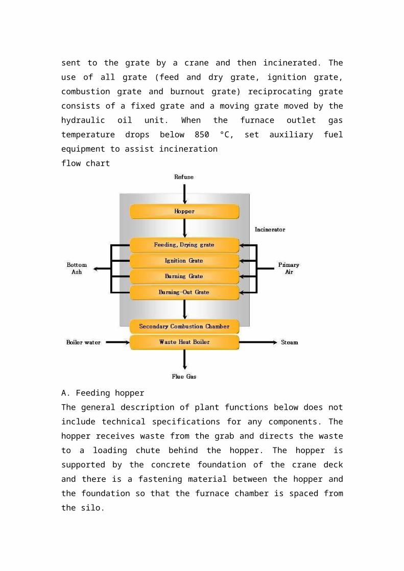
into account appropriate operational plans, problems arising during operation, access to technical professionals, and analysis of incineration operations at home and abroad.C. Process description1. reject the receiving systemOne. The municipal solid waste transported by the garbage truck is weighed on the weighing bridge and then discharged into the garbage bin with a capacity of about 3 days.There are two overhead trains in the bay garbage bin. A crane is running to load the waste into the hopper of the waste bin and the other is in standby. The garbage bin above provides a large garbage shredder.flow chart
2. Waste incineration and incineration systemsGarbage that collects garbage from the garbage can is sent to the grate by a crane and then incinerated. The use of all grate (feed and dry grate, ignition grate, combustion grate and burnout grate) reciprocating grate consists of a fixed grate and a moving grate moved by the hydraulic oil unit. When the furnace outlet gas temperature drops below 850 °C, set auxiliary fuel equipment to
assist incinerationflow chart
A. Feeding hopperThe general description of plant functions below does not include technical specifications for any components. The hopper receives waste from the grab and directs the waste to a loading chute behind the hopper. The hopper is supported by the concrete foundation of the crane deck and there is a fastening material between the hopper and the foundation so that the furnace chamber is spaced from the silo.The chute that guides the waste into the furnace is constantly filled with waste during operation, thereby forming a seal between the combustion chamber and the outside atmosphere. The chute is equipped with a damper to prevent air from entering the combustion chamber during operation stoppage.C. ScorpionThe grate is divided into 4 separate sections: feed, dry, ignited and
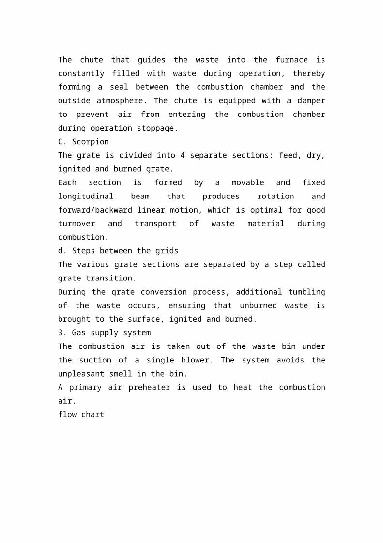
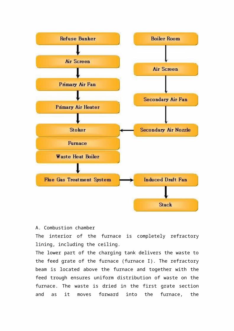
burned grate.Each section is formed by a movable and fixed longitudinal beam that produces rotation and forward/backward linear motion, which is optimal for good turnover and transport of waste material during combustion.d. Steps between the gridsThe various grate sections are separated by a step called grate transition.During the grate conversion process, additional tumbling of the waste occurs, ensuring that unburned waste is brought to the surface, ignited and burned.3. Gas supply systemThe combustion air is taken out of the waste bin under the suction of a single blower. The system avoids the unpleasant smell in the bin.A primary air preheater is used to heat the combustion air.flow chart

A. Combustion chamberThe interior of the furnace is completely refractory lining, including the ceiling.The lower part of the charging tank delivers the waste to the feed grate of the furnace (furnace I). The refractory beam is located above the furnace and together with the feed trough ensures uniform distribution of waste on the furnace. The waste is dried in the first grate section and as it moves forward into the furnace, the forward/backward push motion of the grate beam causes it to roll,
ensuring thorough and effective drying.The heat for drying and ignition is provided in part by the flue gas produced by the combustion zone, partly by the combustion air at the time of overheating, and partly by the thermal radiation from the thermal refractory wall.B rear combustion chamberThe gas stream from the furnace is thoroughly mixed by turbulence and the retention time is achieved in the afterburner at high temperatures.This system results in completely odorless and thoroughly burnt fumes. This is the most important to avoid atmospheric degradation and high temperature corrosion damage on the following boiler surfaces. It also ensures complete combustion of particulate matter generated in the combustion chamber and improves gas purification efficiency.C. Burning airThe burning air is introduced into the furnace through primary and secondary air systems consisting of a separate air system.Once the air is extracted from the waste bin, a negative pressure is maintained and the odor does not affect the environment around the plant.d. One burning airThe primary combustion air is directed to the air box below the grille, from which it is extruded through the stringers and evenly distributed over the entire grille surface.The total amount of air is automatically controlled by the control room.Also, the air distribution of each grate is controlled from the control room. Secondary airThe secondary combustion of the superheated air is independently controlled and injected through the nozzles on the ceiling and walls into the combustion chamber above the grid.
The secondary air needs to ensure the effective burnout of the flue gas and as a burner to burn the high calorific value waste.
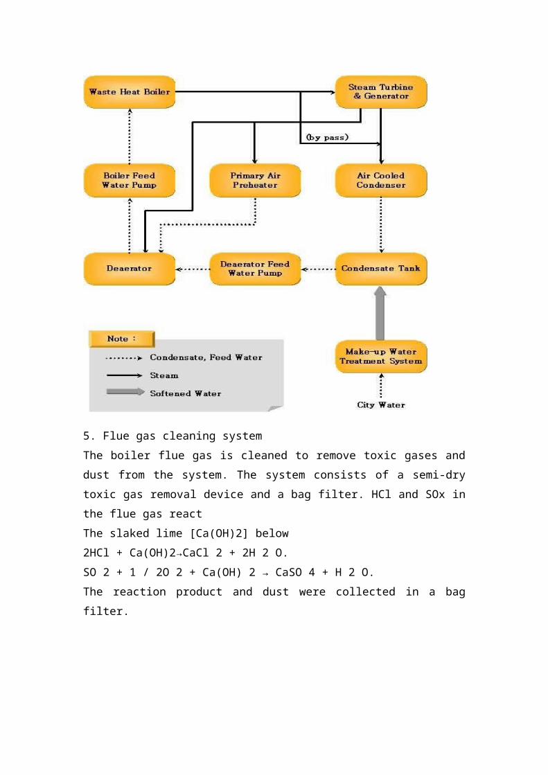
4. Waste heat boilerThe boiler cools the high temperature flue gas and recovers the heat with steam. The boiler is of a natural circulation type. Steam is mainly supplied to the steam turbine. A small amount of steam is generated as a process steam for a deaerator, primary air preheater, soot blower, and the like. .
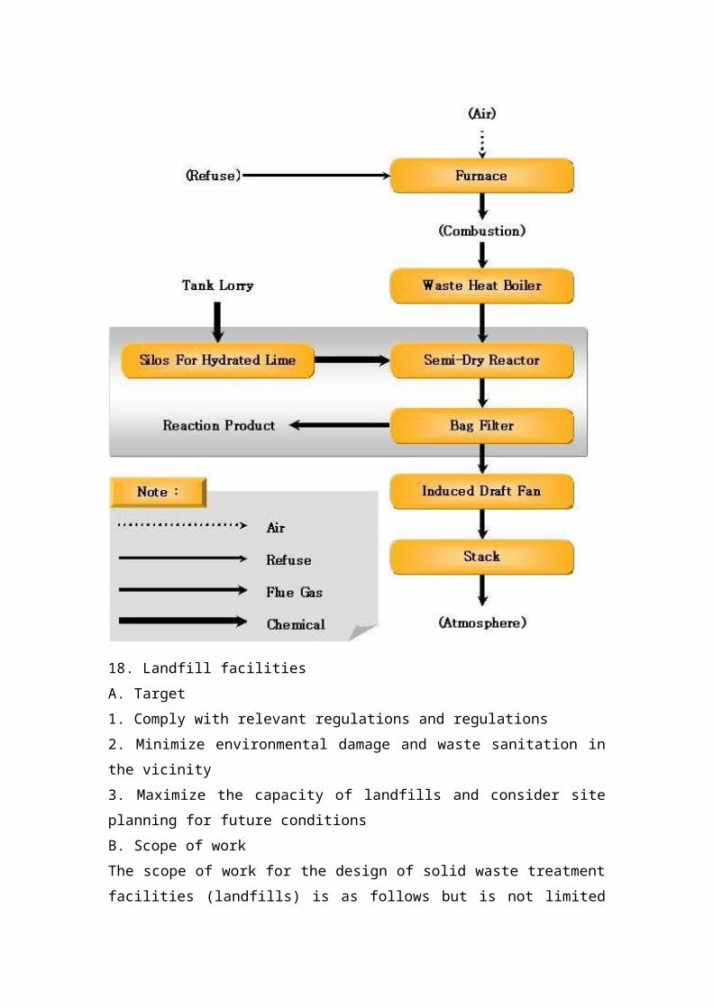
5. Flue gas cleaning systemThe boiler flue gas is cleaned to remove toxic gases and dust from the system. The system consists of a semi-dry toxic gas removal device and a bag filter. HCl and SOx in the flue gas reactThe slaked lime [Ca(OH)2] below
2HCl + Ca(OH)2→CaCl 2 + 2H 2 O.SO 2 + 1 / 2O 2 + Ca(OH) 2 → CaSO 4 + H 2 O.The reaction product and dust were collected in a bag filter.
18. Landfill facilitiesA. Target1. Comply with relevant regulations and regulations2. Minimize environmental damage and waste sanitation in the vicinity3. Maximize the capacity of landfills and consider site planning for future conditions
B. Scope of workThe scope of work for the design of solid waste treatment facilities (landfills) is as follows but is not limited to:1. According to Iraq's waste disposal regulations and waste disposal rules, design standards should be determined after the implementation personnel meet, according to the installation and management standards of the waste treatment facilities.2. The design should follow design criteria discussed with the implementer and related regulations.3. By reviewing the Iraq Basra waste treatment plan, the results of the review should apply to the design.4. Minimize environmental damage, taking into account the sanitary conditions and economic treatment options of the waste.5. By thoroughly reviewing the data from surveys and soil surveys, the results of the relationship between the environment and the site should be applied to the design.C. Specifications1. Catheters and pipesOne. High density polyethylene (HDPE) pipePolyethylene pipes should in principle be constructed by a fusion process to be carried out together with the three essential elements (temperature, time and pressure).In principle all pipes must be fused or flanged to prevent separation and damage from the joint due to uneven sinking.The fusion portion should be inspected by a bead inspection according to the basic model and sample destructive test (bead formation test, bending test).2. Construction of leachate isolation facilitiesOne. Construction method of landfill floor lining1 general provisionsThe provisions of this article must apply to the specifications of bentonite mixing and compacting materials used in landfill lining,
construction and inspection.2 General materials must be stored in a dry and cool place, no moisture, the material will not be wet by the rain.Bentonite should be stacked in a sequence of at least 10 cm from the ground and organized well for inspection and withdrawal. Bentonite should not be stacked on more than 4 layers.When bentonite is stacked in a temporary storage, it must be covered with a moisture barrier. Bentonite must be compacted in fine weather and the protective nonwoven and HDPE panels should be laid as soon as possible after compaction.3 Product Description Bentonite must contain a minimum of 70% montmorillonite content (MB test). Bentonite must be packed in burlap bags or large bags and must be dry. The montmorillonite content and expansion capacity will be verified by testing on the construction site. Other items will be obtained from the product supplier's test record.4 Construction rafts must remove all trees and plants and stones that can penetrate clay sutures.ž Rain has a negative impact on the optimum moisture content. Therefore, you must stop working immediately when it rains. The area that has been worked must be protected from damage.žBefore using, bentonite must be combined to match the Earth's components in the borrow pit. After the design is completed, the bentonite should be properly dispersed and compacted for indoor testing (compaction, water permeability test) to achieve a permeability coefficient of 1 × 10⁻⁷ cm / sec.ž There should be no more than 40 M / M impurities and gravel in the soil mixed with bentonite.The maximum thickness of the bentonite and soil mixture at one time for spreading and compacting is 20 cm. For bottom and inclined surfaces, the mixture should be at least 90% compacted. Also, it must satisfy a permeability coefficient of 1 × 10 -7 cm / sec.
Bentonite construction is greatly affected by the quality of bentonite and soil mixture. Therefore, the mixture should be completely combined until the bentonite and soil quality are uniform.• 2% bentonite must be added to penetrate the edges or corners and the waterproof layer compared to the plane.Only work that can be completed at the end of the day should be done.• Plant roots or seeds, undecomposed organic matter (plant roots, etc.) or insects that grow in the soil cause leakage and may damage the waterproof layer. Therefore, all topsoil must be removed.B. HDPE sheet spreading1 General This specification specifies the items required for HDPE paving construction and inspection mentioned in the construction plan.2. The general standard for materials and materials will be referred to in Schedule 9 "InstallationThe “Waste Treatment Plant Standard” of the “Waste Management Law” implementation regulations of Korea.3 The welding material used for structural extrusion welding must use the same raw materials as the lining base material.The Building Supervision Committee must consult the contractor to determine the temperature, humidity, precipitation, wind speed and direction, and other climatic conditions that limit lining laying and welding. Welding is not performed under the following conditions.- When it rains, it snows, snows, fogs or condensation.- Dust and impurities may be generated when strong winds and penetrating welded parts or when the welding temperature cannot be adjusted- In principle, spreading and welding can only be carried out when the temperature range of 15 cm directly above the HDPE board is 5 to 40 °C.- When measuring the soldering temperature, the temperature must
be at least 5 points taken 150 mm above the surface of the pad soldered portion.welding- All welding must be done by fusion or extrusion- Sheet welding will be overlapped with an overlap length of 75 to 150 mm.- The connecting surface must be kept clean. Do not use chemical reagents. Use cloth to remove dust and impurities. Soldering is performed immediately after the impurities are removed.All sheets not approved by the Construction Supervision Committee must be weldedThe day they spread.4 checkThe contractor is responsible for 100% non-destructive testing (NDT) of the welded parts to verify the water resistance of all main welds. The contractor must submit a test seam result report approved by the construction supervision company. NDT test methods include vacuum testing, air pressure testing and spark testing. The sheet and sheet connections must be tested for air pressure, and the repaired or repaired parts must be vacuum or spark tested.Bentonite pad work1 constructionBentonite should not be installed when it is raining or when there is a lot of water in the work area. When there is water in the work area, water should be drained before installing bentonite.As shown in the construction plan, bentonite must be installed after the construction surface is completely flat.When laying bentonite on an inclined surface, proper anchoring grooves must be used
Fix the bentonite in place. The overlapping parts must be installed so that they are perpendicular to the bottom.

The bentonite must be at least 20 to 30 cm, and a minimum of 0.45 kg/m2 of pure bentonite powder must be spread out at a width of 15 cm.Equipment and trucks must not enter the top of bentonite directly. Bentonite must be covered with a layer of protective material and finished on it. The torn bentonite must be repaired with a bentonite gasket of sufficient size and then secured and protected with a protective coverWhen pipes or other protrusions pass through bentonite, the seal must be sealed with a bentonite sealant and appropriate measures taken.It takes some time before the bentonite is laid to cover the protective layer. These parts must be wrapped with PVC or PE film for protection.Drainage and other measures should be taken before bentonite construction to ensure that they are free of moisture. Measures must also be taken to prevent water hydration.If there is a large amount of rain immediately after the completion of the bentonite construction, and the water content of the bentonite rises above 70%, the fact must be reported to the Building Supervision Committee and appropriate measures such as reconstruction should be taken.2 Physical properties of bentonite mats The contractor must fully understand the stability of bentonite during hydration, resist the shear angle of adjacent slopes, and the internal friction described in the construction plan, and submit it in writing to the Construction Supervision Committee. Request a plan. After approval by the board of directors, materials may be brought to the construction site and construction begins. In addition, the physical properties of bentonite must be tested every 5,000 square meters and the test results submitted to the Construction Supervision Committee.
3. Leachate leakage protection projectA. Non-woven flooring1 General mattersThis specification specifies the requirements for laying a nonwoven fabric for HDPE sheet protection and component separation and induced drainage.Suppliers should have a complete understanding of this specification and architectural drawings in advance, and produce and supply non-woven fabrics based on specifications and architectural drawings. Supplemental material (stitched parts) should be included in the delivery.The supplier is obliged to submit the documents and records required by this specification to the Building Supervision Committee when necessary.The contractor should be faithful to the construction, storage and preservationAccording to this specification and architectural drawings.Tests performed in accordance with this standard will be performed in accordance with the KS and ASTM test methods.The supplier must attach a test record of the authorized agency and the testing agency must be an agency authorized under the Construction Technology Management Act of the Republic of Korea. When necessary, the supervisory committee may take random samples from the factory or deliver the goods at the construction site. The test for random sample extraction will be commissioned by an authorized agency.2 constructionžThe contractor will not use sharp instrument damage materials during the loading and transport of the non-woven fabric, and the non-woven fabric will be used with PP ropes and rollers.Non-woven fabrics should be stacked in a wide, flat place. Before laying the nonwoven, check the bottom for irregular and irregular
large protrusions that affect the material and are approved by the Building Supervision Committee.The roller to be used must be visually inspected. The rollers that failed the visual inspection must be reported immediately to the supplier and the Construction Supervisory Board and replacement products must be used.ž On-site installation should be performed after planning is completed ahead of time. When working on inclined surfaces, the upper part should be fixed with grooves or sandbags to prevent sliding due to the weight of the non-woven fabric or other external forces.ž When using a flat seam to join the nonwoven fabric roll and roll, the roll should overlap at least 50 cm at the bottom, at least 50 cm along the slope, and at least 100 cm perpendicular to the angle of the slope. Also, the nonwoven fabric should be fixed to the upper portion by means of a rope or the like to prevent it from slipping. When the machine cannot be sewn, the non-woven fabric can be constructed by the on-site lap joint method with the approval of the Construction Supervision Committee.1⁄4 Permeability and drainage should not fall on the overlap and should be secured with sandbags and other objects to prevent wind.After the non-woven fabric is laid, special care must be taken to ensure that the non-woven fabric cannot move from its correct position due to other subsequent work, wind or external force.ž The movement of the work vehicle on the surface of the nonwoven fabric should be restricted as much as possible. Any damage caused by the movement of the vehicle on the surface of the nonwoven fabric must be repaired immediately. Damaged parts should be repaired with a non-woven overlap at least at the minimum overlap required at the edges. Such repairs must be approved by the Construction Supervisory Board.
A geonet laying1 General items will be tested in accordance with KS and ASTM test methods.2Storage and construction When storing materials on the construction site, timber or pallets should be laid at the bottom to prevent the material from getting wet. In addition, the protective covering should be covered with a suitable covering.Any impurities should be removed before laying the basket and care must be taken to keep them clean.When laying on a slope, the anchor groove should be secured with the top liner and rolled down the slope. The netting should be smoothed to eliminate any wrinkles.1⁄4 mesh plastic tape should be used to tie nets and metal materials, such as wire may damage the liner and cannot be used.In principle, a net connection should be laid along the length of the slope. Small errors are not allowed under any circumstances. All connections must be made in the upper part and the anchoring structure of the anchoring centre is completed by anchoring.3 inspection and repairOn the day of laying, the Building Supervisory Board must perform a naked eye inspection on the net to see if there is any damage, and if there is any damage, order the contractor to do the proper repair work.The Construction Supervisory Board must check the overlap and joint spacing of the net and re-work when the interval value is different from the above standard value.When the mesh or tears are horizontal and measured 1 meter or longer,The damaged part should be completely cut off and repaired by connecting to a new network.4. Bioreactor landfill methodOne. The general "bioreactor system" is an early landfill stabilization
method that reduces pollution and actively uses landfill gas.A new form of landfill in which liquids including leachate and landfill gas condensate and air are injected into landfills through well-controlled systems to accelerate or enhance the biostability of the waste.Early biostabilization aimed at enhancing landfill waste operations through circulating leachate to provide microbes with a landfill environmentDegradation of biodegradable solid waste.constructionInstall a uniform injection leachate supply facility Install an injection well at the top of the landfill to inject leachate. Analyze the humidity model to determine the optimal radius of the injection well. Install a gas collection facility to collect the generated gas and prevent leakage.Injection well leachate5. Construction of auxiliary facilitiesOne. Construction of weighing station1 GeneralThe 30-ton class, truck specification is provided here to determine the amount of garbage ingested by weighing the garbage truck through the landfill. Weighing will enable analysis of target and actual production that can be used for efficient landfill operations and budget execution.2 Special facts The dimensions installed in this structure must work as follows. When the truck is placed horizontally on the carriage, the load is transmitted to the indicator via the load cell and the value on the value counter is used for weighing. The measured weight is printed simultaneously and recorded by the electronic printer in the statement.The ruler must have sufficient strength and robust construction and must run smoothly. High-quality materials that meet the
requirements of the standard must be manufactured according to the design values and installed according to the weighing for continuous weighting